Wistron NeWeb CB1GI210C Integrate with certified module-End product User Manual UMC I210C Rev 2 3 20150608
Wistron NeWeb Corporation Integrate with certified module-End product UMC I210C Rev 2 3 20150608
Contents
- 1. User Manual V1.0
- 2. Module Installation Guide V1.0
- 3. UMC-I210C User Manual_Rev 3.0_20150824
User Manual V1.0
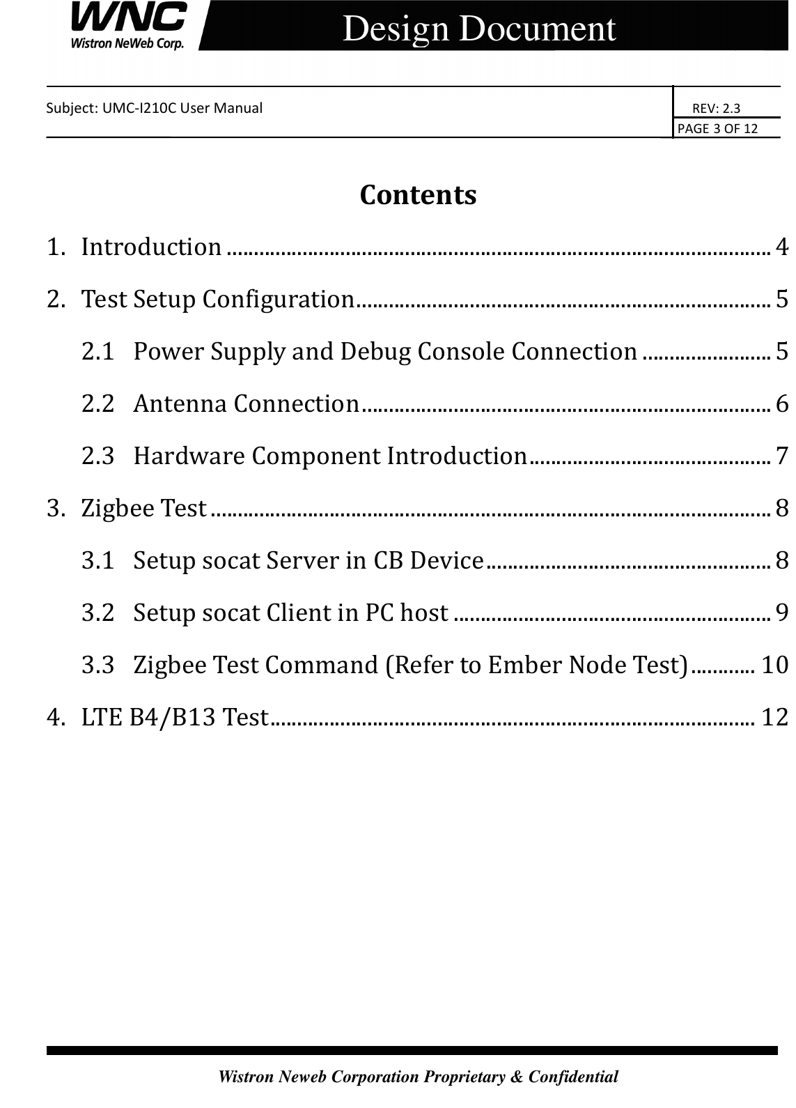
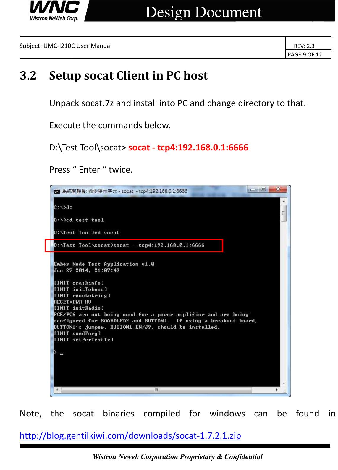
![Subject: UMC-I210C User Manual REV: 2.3 PAGE 5 OF 12 Wistron Neweb Corporation Proprietary & Confidential Design Document 2. Test Setup Configuration 2.1 Power Supply and Debug Console Connection Power on Sequence: I. Connect 12-pin-to-Jig-baord cable II. Attach AC-DC Adaptor & USB Debug Port Cable III. Wait for 20 seconds when system ready (See Note 1) IV. Plug-in Console Port cable [Caution] Improper power on sequence might lead to system boot-up failure! AC-DC 5V Adaptor Interface Board DUT (CB) USB Debug Port Console](https://usermanual.wiki/Wistron-NeWeb/CB1GI210C.User-Manual-V1-0/User-Guide-2648755-Page-5.png)
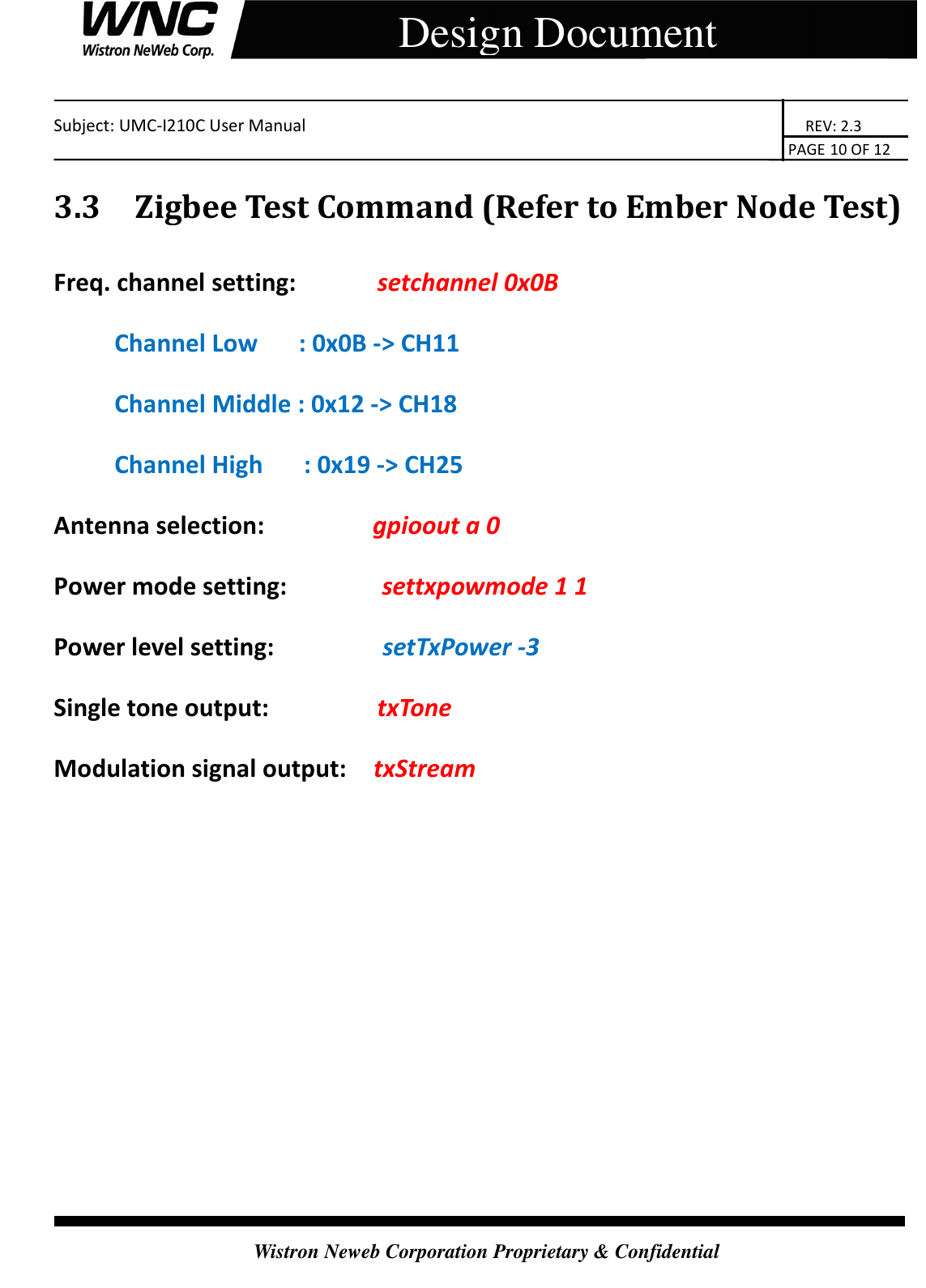
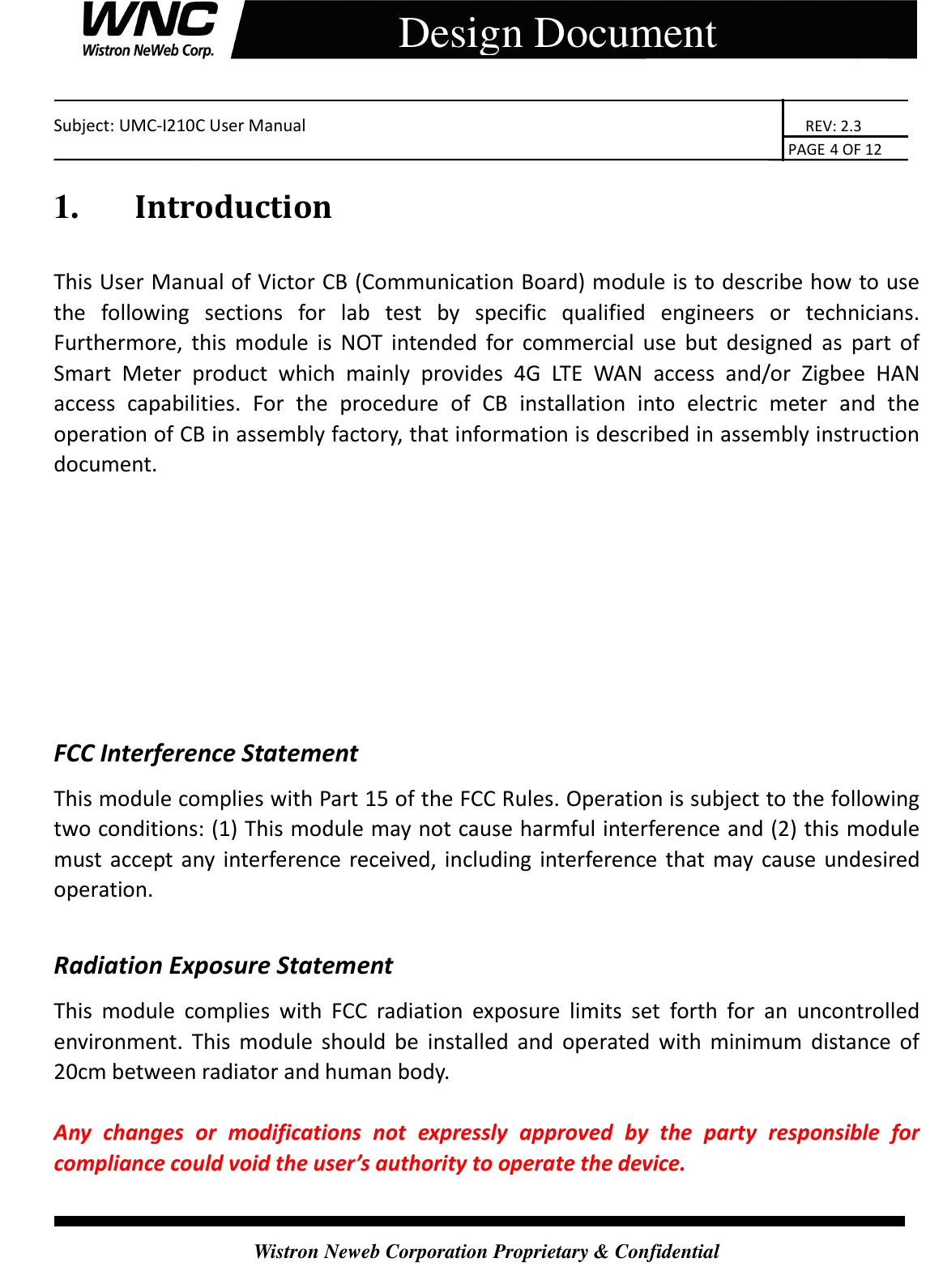
![Subject: UMC-I210C User Manual REV: 2.3 PAGE 8 OF 12 Wistron Neweb Corporation Proprietary & Confidential Design Document 3. Zigbee Test 3.1 Setup socat Server in CB Device Telnet 192.168.0.1 into CB and run the commands below. [root@Grid –NetOS ~] # socat TCP-LISTEN:6666,fork /dev/ttyS2,raw,b115200,echo=0 Login: root Password: gridnet](https://usermanual.wiki/Wistron-NeWeb/CB1GI210C.User-Manual-V1-0/User-Guide-2648755-Page-8.png)