Wulfsberg Electronics Division RT-5000A VHF/ UHF Tactical Transeiver User Manual PRINTING INSTRUCTIONS
Wulfsberg Electronics Division VHF/ UHF Tactical Transeiver PRINTING INSTRUCTIONS
Contents
users manual 2

C-5000 COMMUNICATION MANAGEMENT CONTROLLER
INSTALLATION MANUAL
Page 4-54 Publication No. 150-041118
Section 4 – Electrical Installation Rev C
May 2006
Remove this page.

C-5000 COMMUNICATION MANAGEMENT CONTROLLER
INSTALLATION MANUAL
Publication No. 150-041118 Page 4-55
Rev C Section 4 –Electrical Installation
May 2006
Remove this page and insert 152-140131 Sheet 8 of 17 (Figure 4-11h)

C-5000 COMMUNICATION MANAGEMENT CONTROLLER
INSTALLATION MANUAL
Page 4-56 Publication No. 150-041118
Section 4 – Electrical Installation Rev C
May 2006
Remove this page.

C-5000 COMMUNICATION MANAGEMENT CONTROLLER
INSTALLATION MANUAL
Publication No. 150-041118 Page 4-57
Rev C Section 4 –Electrical Installation
May 2006
Remove this page and insert 152-140131 Sheet 9 of 17 (Figure 4-11i)

C-5000 COMMUNICATION MANAGEMENT CONTROLLER
INSTALLATION MANUAL
Page 4-58 Publication No. 150-041118
Section 4 – Electrical Installation Rev C
May 2006
Remove this page.

C-5000 COMMUNICATION MANAGEMENT CONTROLLER
INSTALLATION MANUAL
Publication No. 150-041118 Page 4-59
Rev C Section 4 –Electrical Installation
May 2006
Remove this page and insert 152-140131 Sheet 10 of 17 (Figure 4-11j)

C-5000 COMMUNICATION MANAGEMENT CONTROLLER
INSTALLATION MANUAL
Page 4-60 Publication No. 150-041118
Section 4 – Electrical Installation Rev C
May 2006
Remove this page.

C-5000 COMMUNICATION MANAGEMENT CONTROLLER
INSTALLATION MANUAL
Publication No. 150-041118 Page 4-61
Rev C Section 4 –Electrical Installation
May 2006
Remove this page and insert 152-140131 Sheet 11 of 17 (Figure 4-11k)

C-5000 COMMUNICATION MANAGEMENT CONTROLLER
INSTALLATION MANUAL
Page 4-62 Publication No. 150-041118
Section 4 – Electrical Installation Rev C
May 2006
Remove this page.

C-5000 COMMUNICATION MANAGEMENT CONTROLLER
INSTALLATION MANUAL
Publication No. 150-041118 Page 4-63
Rev C Section 4 –Electrical Installation
May 2006
Remove this page and insert 152-140131 Sheet 12 of 17 (Figure 4-11l)

C-5000 COMMUNICATION MANAGEMENT CONTROLLER
INSTALLATION MANUAL
Page 4-64 Publication No. 150-041118
Section 4 – Electrical Installation Rev C
May 2006
Remove this page.

C-5000 COMMUNICATION MANAGEMENT CONTROLLER
INSTALLATION MANUAL
Publication No. 150-041118 Page 4-65
Rev C Section 4 –Electrical Installation
May 2006
Remove this page and insert 152-140131 Sheet 13 of 17 (Figure 4-11m)

C-5000 COMMUNICATION MANAGEMENT CONTROLLER
INSTALLATION MANUAL
Page 4-66 Publication No. 150-041118
Section 4 – Electrical Installation Rev C
May 2006
Remove this page.

C-5000 COMMUNICATION MANAGEMENT CONTROLLER
INSTALLATION MANUAL
Publication No. 150-041118 Page 4-67
Rev C Section 4 –Electrical Installation
May 2006
Remove this page and insert 152-140131 Sheet 14 of 17 (Figure 4-11n)

C-5000 COMMUNICATION MANAGEMENT CONTROLLER
INSTALLATION MANUAL
Page 4-68 Publication No. 150-041118
Section 4 – Electrical Installation Rev C
May 2006
Remove this page.

C-5000 COMMUNICATION MANAGEMENT CONTROLLER
INSTALLATION MANUAL
Publication No. 150-041118 Page 4-69
Rev C Section 4 –Electrical Installation
May 2006
Remove this page and insert 152-140131 Sheet 15 of 17 (Figure 4-11o)

C-5000 COMMUNICATION MANAGEMENT CONTROLLER
INSTALLATION MANUAL
Page 4-70 Publication No. 150-041118
Section 4 – Electrical Installation Rev C
May 2006
Remove this page.

C-5000 COMMUNICATION MANAGEMENT CONTROLLER
INSTALLATION MANUAL
Publication No. 150-041118 Page 4-71
Rev C Section 4 –Electrical Installation
May 2006
Remove this page and insert 152-140131 Sheet 16 of 17 (Figure 4-11p)

C-5000 COMMUNICATION MANAGEMENT CONTROLLER
INSTALLATION MANUAL
Page 4-72 Publication No. 150-041118
Section 4 – Electrical Installation Rev C
May 2006
Remove this page.

C-5000 COMMUNICATION MANAGEMENT CONTROLLER
INSTALLATION MANUAL
Publication No. 150-041118 Page 4-73
Rev C Section 4 –Electrical Installation
May 2006
Remove this page and insert 152-140131 Sheet 17 of 17 (Figure 4-11q)

C-5000 COMMUNICATION MANAGEMENT CONTROLLER
INSTALLATION MANUAL
Page 4-74 Publication No. 150-041118
Section 4 – Electrical Installation Rev C
May 2006
Remove this page.
C-5000 COMMUNICATION MANAGEMENT CONTROLLER
INSTALLATION MANUAL
Publication No. 150-041118 Page 4-75
Rev C Section 4 –Electrical Installation
May 2006
F. C-5000 Communication Management Controller Installation Wiring Considerations
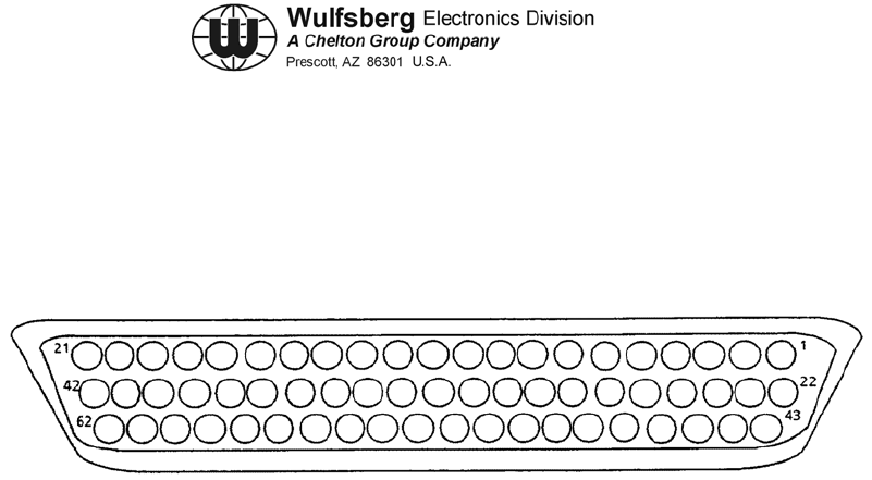
(1) C-5000 Transceiver (FLEXCOMM I) Connector P501 or P502.
Figure 4-12. C-5000 Transceiver (FLEXCOMM I) Connector P501 or P502

C-5000 COMMUNICATION MANAGEMENT CONTROLLER
INSTALLATION MANUAL
Page 4-76 Publication No. 150-041118
Section 4 – Electrical Installation Rev C
May 2006
(2) C-5000 Transceiver (FLEXCOMM I) Connector P501 or P502.
PIN SIGNAL NAME PIN SIGNAL NAME
1 TONE C LINE 32 4 MHZ CHN LINE
2 TX PWR LITE 33 MIC LO/PTT
3 0.08 MHZ CHN LINE 34 0.01 MHZ CHN LINE
4 120 MHZ CHN LINE 35 0.005 MHZ CHN LINE
5 80 MHZ CHN LINE 36 RESRV SPARE GUARD TONE
ENABLE
6 TONE E LINE (MSB) 37 40 MHZ CHN LINE
7 SPARE #2 38 CIPHER/PLAIN
8 ON/OFF 39 TX
9 10.0025 MHZ CHN LINE 40 PLAIN/CIPHER
10 2 MHZ CHN LINE 41 AUDIO LO
11 MIC HI 42 MN VOL SET
12 TONE A LINE (LSB) 43 TONE B LINE
13 MAIN RCVR AUDIO DISABLE 44 0.04 MHZ CHN LINE
14 TX PWR SELECT 45 EXTERNAL ENCODE IN
15 CHN MEMORY DISCRETE NO. 2 46 DF DISABLE
16 CHN MEMORY DISCRETE NO. 3 47 TAKE CONTROL
17 CHN MEM DISCRETE NO. 4 48 GUARD SQUELCH LITE
18 SPARE #3 49 0.1 MHZ CHN LINE
19 GD SELECT 50 GD VOL SET
20 ZEROIZE 51 800 MHZ CHN LINE
21 UNSQUELCHED MAIN AUDIO 52 0.4 MHZ CHN LINE
22 SHIELD 53 0.2 MHZ CHN LINE
23 MAIN TONE ENABLE 54 GUARD RCVR AUDIO DISABLE
24 SPARE #1 55 0.8 MHZ CHN LINE
25 SQUELCH DISABLE 56 CHN MEMORY DISCRETE NO. 1
26 10 MHZ CHN LINE 57 0.02 MHZ CHN LINE
27 100 MHZCHN LINE 58 MAIN SQUELCH LITE
28 400 MHZ CHN LINE 59 CHN MEM DISCRETE NO. 5
29 TONE D LINE 60 UNSQUELCHED GUARD AUDIO
30 1 MHZ CHN LINE 61 AUDIO HI
31 8 MHZ CHN LINE 62 AUX GND NO. 20 AWG
Table 4-6. C-5000 Transceiver (FLEXCOMM I) Connector P501 or P502

C-5000 COMMUNICATION MANAGEMENT CONTROLLER
INSTALLATION MANUAL
Publication No. 150-041118 Page 4-77
Rev C Section 4 –Electrical Installation
May 2006
Pin(s) - Signal Name
3, 4, 5, 9, 10, 26, 27, 28, 30, 31, 32, 34, 35, 37, 44, 49, 51, 52, 53, 55, 57 - CHANNEL
LINES
The channeling lines use BCD (Binary Coded Decimal) negative logic to control
the Transceiver channel frequency. These lines are grounded by the Control Unit
to channel the Transceiver to the selected frequency. The channel is determined
by adding the weighted value of each line. To channel a transceiver to 157.135
MHz, the following lines would be grounded:
100 MHz line
40 MHz line
10 MHz line
4 MHz line
2 MHz line
1 MHz line
0.1 MHz line
0.02 MHz line
0.01 MHz line
0.005 MHz line
157.135 MHz
Unselected channel lines should exceed +8 Vdc.
1, 6, 12, 29, 43 - TONE A, B, C, D, E
These lines are used to provide pre-programmed control of a synthesized
CTCSS encoder/decoder in the transceiver. The order of the lines follows a
binary code with E the most significant bit and A the least significant. Logic "0" is
a ground line and logic "1" must be greater than 8 volts. Refer to Section 6,
Preset Channel Programming, for information on programming tones and Table
6-2, Section 6, for available frequencies.
23 - MAIN TONE ENABLE
This line, when grounded, will activate the continuous tone controlled squelch
system (CTCSS) for either transmit tone encode or main receiver tone decode.
The tone frequency is determined by the Tone A, B, C, D, E lines.
8 - ON/OFF
This line, when grounded, will activate the 28 V system relay and provide +27.5
Vdc aircraft power to the Transceiver.
13 - MAIN RX AUDIO DISABLE
Grounding this line mutes Main Receiver audio, but does not affect sidetone or
Guard Receiver audio. The main squelch test function is disabled, yet the main
channel indicator shows channel activity.

C-5000 COMMUNICATION MANAGEMENT CONTROLLER
INSTALLATION MANUAL
Page 4-78 Publication No. 150-041118
Section 4 – Electrical Installation Rev C
May 2006
Pin(s) - Signal Name
54 - GUARD RX AUDIO DISABLE
Grounding this line disables guard audio, but does not affect Main Receiver or
sidetone audio. The guard channel indicator continues to indicate guard channel
activity.
58 - MAIN SQUELCH LITE
The Transceiver pulls this line low to activate the main squelch annunciator in the
Control Unit.
48 - GUARD SQUELCH LITE
The Transceiver Guard Module pulls this line low to activate the guard squelch
annunciator in the Control Unit.
2 - TX POWER LITE
The transceiver pulls this line low to activate the transmit annunciator in the
Control Unit.
25 - SQUELCH DISABLE
This line is grounded by the test (squelch disable) button on the Control Unit. It
opens the squelch gate for the Main or Guard Receiver unless:
• In the Transmit Mode.
• Main or Guard RCVR Audio is disabled by the Control Unit.
• Frequency Synthesizer not locked (Main only).
In addition, the Main and Guard Squelch indicators will activate unless disabled
by the following conditions:
• Transmit Mode.
• Frequency Synthesizer not locked (Main only)
15, 16, 56 RESERVED SPARE
These lines provide a user programmable combination of discrete electronic
switches for each channel. Each channel memory discrete state may differ
between transmit and receive on any channel. These outputs are programmed
when the channel information and tone code information are entered into the
Control Unit.

C-5000 COMMUNICATION MANAGEMENT CONTROLLER
INSTALLATION MANUAL
Publication No. 150-041118 Page 4-79
Rev C Section 4 –Electrical Installation
May 2006
Pin(s) - Signal Name
Some possible uses for these include:
• Antenna switching
• External encoder enable (disable).
• External decoder enable (disable).
• Any functional or equipment switching associated with a given channel.
These switch closures may be combined with a digital decoder to expand the
capabilities.
These switches are open collector drivers. Open switch voltages may not exceed
+30 V, and in the closed condition, the switches will sink up to 40 mA.
62 - CONTROL UNIT GROUND
This line provides signal ground reference for the Control Unit. (The Control Unit
electronics are isolated from the chassis).
41, 61 - AUDIO HI AND LO
These lines provide a balanced 600 Ohm audio output from the Transceiver and
are set for 100 mW into a 600 Ohm load. (7.75 Vrms)
11, 33 - MIC HI AND LO/PTT
These lines are used for voice modulation and to enable the transmitter. Mic
sensitivity is factory set for an input of 0.25VRMS at 1 kHz to provide ±3 kHz FM
deviation, 85% AM modulation. The MIC LO/PTT line activates the transmitter
when grounded and disables the receiver outputs.
39 – TX, Transceiver Or Control
The Transceiver and control pull their respective TX lines low during transmit to
provide TX information to auxiliary equipment.
45 - EXTERNAL ENCODE IN
This line provides for modulating the transmitter from external encoding devices
in the frequency range of 60 to 3000Hz. Inputs of 1.0 Vrms will yield
approximately ±2.5 to
±3 kHz deviation. The RT-138F and RT-406F Frequency Range is approximately
1Hz to 6 kHz.

C-5000 COMMUNICATION MANAGEMENT CONTROLLER
INSTALLATION MANUAL
Page 4-80 Publication No. 150-041118
Section 4 – Electrical Installation Rev C
May 2006
Pin(s) - Signal Name
21 - UNSQUELCHED MAIN AUDIO
This line provides unsquelched audio from the Main Receiver. The frequency
response is flat from 60 Hz to 5 kHz. A received signal of 1 kHz tone at ±3 kHz
deviation will produce approximately 0.6 Vrms into a 20k Ohm load. The RT-
138F and RT-406F Frequency Range is approximately 1 Hz to 6 kHz.
60 - UNSQUELCHED GUARD AUDIO
This line provides an unsquelched audio output of the Guard Receiver for use
with external audio decoders. The frequency response is approximately flat from
60 Hz to
5 kHz. Standard 3 kHz modulation of a 1 kHz tone will produce approximately 0.6
Vrms into a 20k Ohm load.

C-5000 COMMUNICATION MANAGEMENT CONTROLLER
INSTALLATION MANUAL
Publication No. 150-041118 Page 4-81
Rev C Section 4 –Electrical Installation
May 2006
Remove this page and insert 147-014991 Sheet 1 of 5 (Figure 4-13a)

C-5000 COMMUNICATION MANAGEMENT CONTROLLER
INSTALLATION MANUAL
Page 4-82 Publication No. 150-041118
Section 4 – Electrical Installation Rev C
May 2006
Remove this page.

C-5000 COMMUNICATION MANAGEMENT CONTROLLER
INSTALLATION MANUAL
Publication No. 150-041118 Page 4-83
Rev C Section 4 –Electrical Installation
May 2006
Remove this page and insert 147-014991 Sheet 2 of 5 (Figure 4-13b)

C-5000 COMMUNICATION MANAGEMENT CONTROLLER
INSTALLATION MANUAL
Page 4-84 Publication No. 150-041118
Section 4 – Electrical Installation Rev C
May 2006
Remove this page.

C-5000 COMMUNICATION MANAGEMENT CONTROLLER
INSTALLATION MANUAL
Publication No. 150-041118 Page 4-85
Rev C Section 4 –Electrical Installation
May 2006
Remove this page and insert 147-014991 Sheet 3 of 5 (Figure 4-13c)

C-5000 COMMUNICATION MANAGEMENT CONTROLLER
INSTALLATION MANUAL
Page 4-86 Publication No. 150-041118
Section 4 – Electrical Installation Rev C
May 2006
Remove this page.

C-5000 COMMUNICATION MANAGEMENT CONTROLLER
INSTALLATION MANUAL
Publication No. 150-041118 Page 4-87
Rev C Section 4 –Electrical Installation
May 2006
Remove this page and insert 147-014991 Sheet 4 of 5 (Figure 4-13d)

C-5000 COMMUNICATION MANAGEMENT CONTROLLER
INSTALLATION MANUAL
Page 4-88 Publication No. 150-041118
Section 4 – Electrical Installation Rev C
May 2006
Remove this page.

C-5000 COMMUNICATION MANAGEMENT CONTROLLER
INSTALLATION MANUAL
Publication No. 150-041118 Page 4-89
Rev C Section 4 –Electrical Installation
May 2006
Remove this page and insert 147-014991 Sheet 5 of 5 (Figure 4-13e)

C-5000 COMMUNICATION MANAGEMENT CONTROLLER
INSTALLATION MANUAL
Page 4-90 Publication No. 150-041118
Section 4 – Electrical Installation Rev C
May 2006
Remove this page
.
C-5000 COMMUNICATION MANAGEMENT CONTROLLER
INSTALLATION MANUAL
Publication No. 150-041118 Page 4-91
Rev C Section 4 –Electrical Installation
May 2006
G. C-5000 Transceiver Interface, RT-9600, RT-9600F, RT-7200 Transceivers
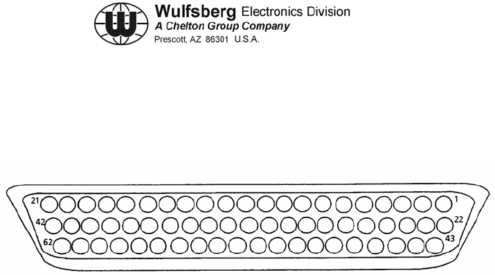
(1) Connector P501/P502
Figure 4-14. Connector P501/P502

C-5000 COMMUNICATION MANAGEMENT CONTROLLER
INSTALLATION MANUAL
Page 4-92 Publication No. 150-041118
Section 4 – Electrical Installation Rev C
May 2006
(2) C-5000 Transceiver (RT-9600(F)/7200) Connector P50X (P501, P502, or P503)
PIN SIGNAL NAME PIN SIGNAL NAME
1 TONE SELECT C 32 4 MHZ
2 TX POWER ANNUNCIATE 33 PTT
3 0.08 MHZ 34 0.01 MHZ
4 20 MHZ 35 0.005 MHZ
5 80 MHZ 36 GUARD TONE ENABLE
6 TONE E 37 RT7200: 40 MHZ, RT9600(F): .0025
MHZ, RT9600F w/DVP/DES: 40 MHz
7 SPARE #2 38 RT7200, RT9600(F):CIPHER/PLAIN
RT9600F w/DVP/DES: CH PVT/STD
8 ON/OFF 39 RT7200, RT9600(F): TX RT9600F
w/DVP/DES: RAD PTT
9 RT7200: 40 MHZ, RT9600(F): .0025
MHZ, RT960OF w/DVP/DES:
.002MHZ
40 PLAIN/CIPHER
10 2 MHZ 41 AUDIO LO
11 MIC HI 42 MAIN VOLUME
12 TONE SELECT A 43 TONE SELECT B
13 MAIN AUDIO INHIBIT 44 0.04 MHZ
14 TX PWR SELECT 45 EXTERNAL CTCSS ENCODE IN
15 CHN MEMORY DISCRETE NO. 2 46 DF DISABLE
16 CHN MEMORY DISCRETE NO. 3 47 TAKE CONTROL
17 CHN MEMORY DISCRETE NO. 4 48 GUARD SQUELCH ANNUNCIATE
18 SPARE #3 49 0.1 MHZ
19 GUARD SELECT 50 GUARD VOLUME
20 ZEROIZE 51 800 MHZ
21 UNSQUELCHED MAIN AUDIO 52 0.4 MHZ
22 SHIELD 53 0.2 MHz
23 TONE SELECT D 54 EXTERNAL GUARD AUDIO INHIBIT
24 SPARE #1 55 0.8 MHZ
25 SQUELCH DISABLE 56 CHN MEMORY DISCRETE NO. 1
26 10 MHZ 57 0.02 MHz
27 100 MHZ 58 MAIN SQUELCH ANNUNCIATE
28 400 MHZ 59 CHN MEM DISCRETE NO. 5
29 TONE D 60 UNSQUELCHED GUARD AUDIO
30 1 MHz 61 AUDIO HI
31 8 MHZ 62 CONTROL GROUND 22 AWG
Table 4-7. C-5000 Transceiver (RT-9600(F)/7200) Connector P50X (P501, P502, or P503)

C-5000 COMMUNICATION MANAGEMENT CONTROLLER
INSTALLATION MANUAL
Publication No. 150-041118 Page 4-93
Rev C Section 4 –Electrical Installation
May 2006
Pin(s) - Signal Name
13, 14, 15, 16 - AUDIO AND SIDETONE HI AND LO
These wires are provided separately for those systems that have separate
transmitter sidetone circuits. They should be paralleled when driving a speaker
directly. 10 Watt audio rated transceivers are not accommodated. In the case of
the 100 mW transceivers, the audio and sidetone outputs (output impedance of
600 Ohms) must be set for 7.8 Vrms into 600 Ohms.
54 - DF DISABLE
This line will disable the linear IF inside the unit and provide superior squelch
action and sensitivity when connected airframe ground. It should be permanently
grounded at the mounting rack when DF equipment is not installed in the aircraft.
If used with DF equipment, this line must be open during Direction Finding
operations.
19 - DF AUDIO
Provides an audio output for use with DF equipment requiring AM receiver
response. With an output impedance of 500 Ohms, the DF Audio output can
supply 400 mVrms open circuit with an RF signal modulated 50% at 1000 Hz.
When the RT-7200 or RT-9600(F) is used in conjunction with the Collins DF301E
automatic Direction Finder, knowledge of the Transceiver modulation phase
delay at
5.68 kHz is necessary for proper DF301E compensation. This phase information
is found on a label on the rear panel of the RT-7200, or RT-9600, RT-9600F.
For DF or ADF systems designed to be used in conjunction with FM receivers,
use UNSQUELCHED MAIN AUDIO as the audio connection from the transceiver
to the DF or ADF unit.
12 - UNSQUELCHED MAIN AUDIO
Buffered output of the main FM receiver, unaffected by squelch action. Provided
for use with external audio decoders. Standard modulation produces 0.58 Vrms
into 1k Ohm or greater impedance. Do not load this output with less than 600
Ohms.
30 - UNSQUELCHED GUARD AUDIO
Buffered output for the guard receiver, unaffected by squelch action. Provided for
use with external audio decoders. Standard modulation produces 0.58 Vrms into
1k Ohm or greater impedance. Do not load this output with less than 600 Ohms.
26 - MAIN AUDIO INHIBIT
When grounded, will mute audio outputs from the main receiver.

C-5000 COMMUNICATION MANAGEMENT CONTROLLER
INSTALLATION MANUAL
Page 4-94 Publication No. 150-041118
Section 4 – Electrical Installation Rev C
May 2006
Pin(s) - Signal Name
25 - EXTERNAL GUARD AUDIO INHIBIT
When grounded, will mute audio outputs for the guard receiver.
18 - EXTERNAL CTCSS TONE IN
Provision for modulating the transmitter with audio outside the normal audio
frequency range of 300 to 3000 Hz. Approximately 0.3 Vrms will give 5 kHz
deviation.
27 - TRANSMITTER POWER SELECT
When used with control units not providing transmitter power selector switches,
grounding this line at the mounting rack will provide 10 watts of RF output power.
The C-920 has this line grounded inside the control unit and will provide 10 watts
when used.
65, 66 - 14V SWITCHED
Provision for switched 14 V power from the RT-7200/RT-9600. These pins will
provide 14 Vdc. Exercise caution not to exceed a combined current drain of 500
mA from pins 65 and 66.
64 - PTT OUT
May be used to key external accessories such as Tone Encoders. This pin is
grounded through the microphone PTT switch.

C-5000 COMMUNICATION MANAGEMENT CONTROLLER
INSTALLATION MANUAL
Publication No. 150-041118 Page 4-95
Rev C Section 4 –Electrical Installation
May 2006
Remove this page and insert 147-014992 Sheet 1 of 3 (Figure 4-15a)

C-5000 COMMUNICATION MANAGEMENT CONTROLLER
INSTALLATION MANUAL
Page 4-96 Publication No. 150-041118
Section 4 – Electrical Installation Rev C
May 2006
Remove this page.

C-5000 COMMUNICATION MANAGEMENT CONTROLLER
INSTALLATION MANUAL
Publication No. 150-041118 Page 4-97
Rev C Section 4 –Electrical Installation
May 2006
Remove this page and insert 147-014992 Sheet 2 of 3 (Figure 4-15b)

C-5000 COMMUNICATION MANAGEMENT CONTROLLER
INSTALLATION MANUAL
Page 4-98 Publication No. 150-041118
Section 4 – Electrical Installation Rev C
May 2006
Remove this page.

C-5000 COMMUNICATION MANAGEMENT CONTROLLER
INSTALLATION MANUAL
Publication No. 150-041118 Page 4-99
Rev C Section 4 –Electrical Installation
May 2006
Remove this page and insert 147-014992 Sheet 3 of 3 (Figure 4-15c)

C-5000 COMMUNICATION MANAGEMENT CONTROLLER
INSTALLATION MANUAL
Page 4-100 Publication No. 150-041118
Section 4 – Electrical Installation Rev C
May 2006
Remove this page.

C-5000 COMMUNICATION MANAGEMENT CONTROLLER
INSTALLATION MANUAL
Publication No. 150-041118 Page 4-101
Rev C Section 4 –Electrical Installation
May 2006
H. Special Options
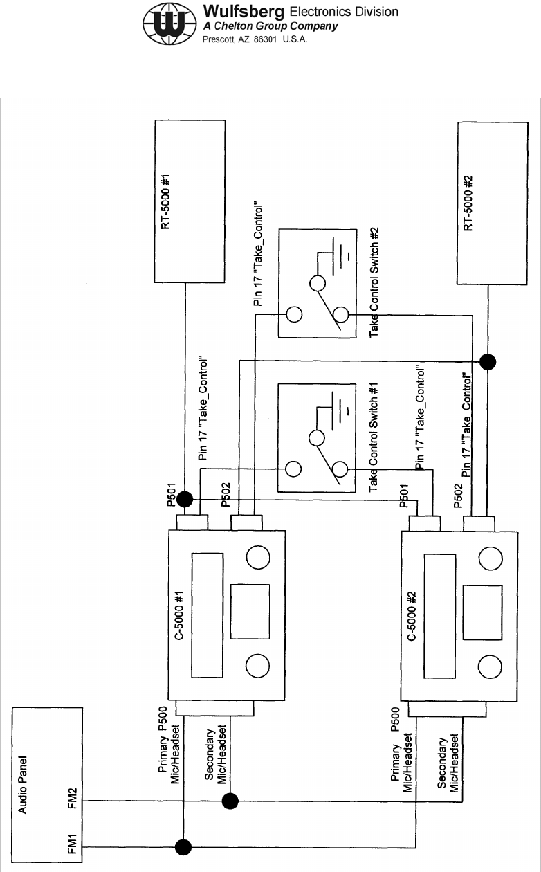
(1) Take_Control
Two C-5000's can be wired so that they can share the control of a RT-5000. To
implement this feature, the installer must make use of the "Take_Control" feature. Please
review Figure 4-16 that shows the installation of two C-5000's sharing control of two
RT-5000's.
For two C-5000's to share the control of a RT-5000 the aircraft wiring must be made as
follows:
a) The wiring harness should have wires going between P501 from BOTH control
heads to RT-5000 #1.
b) In addition, Pin 17 from each P501 connector must go to a switch that grounds
one or the other Pin 17. When the C-5000 sees a ground on Pin 17 of its P501
connector, it gives up control of the RT-5000 to the other C-5000. The display
of the control head without control will indicate "NO CONTROL" on either the
top or bottom line of the display depending on if it is Radio #1 or Radio #2
respectively.
NOTE: If a second RT-5000 is also being shared between the two C-5000's the
same arrangement must go between P502 connectors AND A SECOND
"Take_Control" switch must be installed.
NOTE: Take_Control Switches should be clearly labeled to reduce operator
confusion.
(2) Microphone/Headset Configuration
Versions of the C-5000 with part numbers 31300-12XX-XXOO have the primary
microphone and headset audio's ports on P500 hardwired to the radio connected to
P501. The secondary Microphone and headset ports on P500 are hardwired to the radio
connected to P502. The top line of the display indicates the status of the radio connected
to P501 and the bottom line of the display indicates the status of the radio connected to
P502.
If two C-5000's are sharing radio #1, the primary mic/headset ports of the P500
connectors must be connected together respectively and then tied into the FM1 port (or
however its labeled) of the audio panel. Similarly if two C-5000's are sharing radio #2, the
secondary mic/headset ports of on the P500 connectors must be connected together and
then tied into the FM2 port of the audio panel.

C-5000 COMMUNICATION MANAGEMENT CONTROLLER
INSTALLATION MANUAL
Page 4-102 Publication No. 150-041118
Section 4 – Electrical Installation Rev C
May 2006
(3) Explanation of Example System
In the example system shown in Figure 4-16 two C-5000's part number 31300-1202-1220
are sharing the control of two RT-5000's. Note the following key elements of the wiring:
a) The wires between P501 of both C-5000's are built in a "Y" configuration and
run to RT-5000 #1.
b) The write between P502 of both C-5000's are built in a "Y" configuration and
run to RT-5000 #2.
c) Two "Take_Control" switches (one for each transceiver) allow the operator to
switch the control of a radio between control heads.
d) The primary headset/microphone audio's on P500 of each C-5000 are
paralleled and connected to the FM1 position on the audio panel. The
secondary headset/microphone audio's on P500 of each C-5000 are paralleled
and connected to FM2 position on the audio panel.
If an operator wants to control RT-5000 #1 with C-5000 #1, they put the Take_Control
switch for radio #1 in the position that grounds pin 17 of P501 on C-5000 #2. At this point,
C-5000 #2 gives up control of RT-5000 #1 and displays "NO CONTROL" on the top line
of its display. C-5000 #1 will now show the status of RT-5000 #1 on the top line of its
display To transmit on radio #1, the operator tunes the audio panel to FM1 and
pushes the PTT switch.
If an operator wants to control RT-5000 #1 with C-5000 #2, they put the Take_Control
switch for radio #1 in the position that grounds pin 17 of P501 on C-5000 #1. At this point,
C-5000 #1 gives up control of RT-5000 #1 and displays "NO CONTROL" on the top line
of its display. C-5000 #2 will now show the status of RT-5000 #1 on the top line of its
display To transmit on radio #1, the operator tunes the audio panel to FMI and
pushes the PTT switch.
If an operator wants to control RT-5000 #2 with C-5000 #1, they put the Take_Control
switch for radio #2 in the position that grounds pin 17 of P501 on C-5000 #2. At this point,
C-5000 #2 gives up control of RT-5000 #2 and displays "NO CONTROL" on the bottom
line of its display. C-5000 #1 will now show the status of RT-5000 #2 on the bottom line of
its display To transmit on radio #2, the operator tunes the audio panel to FM2 and
pushes the PTT switch.
If an operator wants to control RT-5000 #2 with C-5000 #2, they put the Take_Control
switch for radio #2 in the position that grounds pin 17 of P501 on C-5000 #1. At this point,
C-5000 #1 gives up control of RT-5000 #2 and displays "NO CONTROL" on the bottom
line of its display. C-5000 #2 will now show the status of RT-5000 #2 on the bottom line of
its display To transmit on radio #2, the operator tunes the audio panel to FM2 and
pushes the PTT switch.

C-5000 COMMUNICATION MANAGEMENT CONTROLLER
INSTALLATION MANUAL
Publication No. 150-041118 Page 4-103
Rev C Section 4 –Electrical Installation
May 2006
All the above boils down to the following: To use RT-5000 #1, put the "Take_Control"
switch in the position so the operators control head shows the status of RT-5000 #1. To
transmit, put the audio panel on FM1. Do the same for transceiver #2 except use
Take_Control switch for RT-5000 #2 and then select FM2 on the audio panel.
If an operator wants to control both RT-5000's from one control head, put the
Take_Control switches in the position that shows the status of both radios on the control
head. Use the FM1 position on the audio panel when talking on RT-5000 #1. Use the
FM2 position on the audio panel when talking on RT-5000 #2.
Other Key Points / Operational Considerations:
a) At no time can both control heads EVER tune the same transceiver. Only one
control can have control of a transceiver at any time. There is no
communication between the two control heads so the head without control will
not show anything other than "NO CONTROL".
b) Mic/Headset audio for transceiver #1 is connected to the Primary mic/headset
port of P500. To transmit on RT-5000 #1 the user must put the audio panel to
the FM1 position regardless of which control head has control of transceiver
#1.
c) Mic/headset audio for transceiver #2 is connected to the Secondary
mic/headset port of P500. To transmit on RT-5000 #2 the user must put the
audio panel to the FM2 position regardless of which control head has control of
transceiver #2.
C-5000 COMMUNICATION MANAGEMENT CONTROLLER
INSTALLATION MANUAL
Page 4-104 Publication No. 150-041118
Section 4 – Electrical Installation Rev C
May 2006
Figure 4-16 Dual C-5000/RT-5000 with Take_Control Block Diagram

C-5000 COMMUNICATION MANAGEMENT CONTROLLER
INSTALLATION MANUAL
Publication No. 150-041118 Page 4-105
Rev C Section 4 –Electrical Installation
May 2006
Remove this page and insert 124-015911 Sheet 1 of 2 (Figure 4-17a)

C-5000 COMMUNICATION MANAGEMENT CONTROLLER
INSTALLATION MANUAL
Page 4-106 Publication No. 150-041118
Section 4 – Electrical Installation Rev C
May 2006
Remove this page.

C-5000 COMMUNICATION MANAGEMENT CONTROLLER
INSTALLATION MANUAL
Publication No. 150-041118 Page 4-107
Rev C Section 4 –Electrical Installation
May 2006
Remove this page and insert 124-015911 Sheet 2 of 2 (Figure 4-17b)

C-5000 COMMUNICATION MANAGEMENT CONTROLLER
INSTALLATION MANUAL
Page 4-108 Publication No. 150-041118
Section 4 – Electrical Installation Rev C
May 2006
Remove this page.

C-5000 COMMUNICATION MANAGEMENT CONTROLLER
INSTALLATION MANUAL
Publication No. 150-041118 Page 4-109
Rev C Section 4 –Electrical Installation
May 2006
Remove this page and insert 124-015910 Sheet 1 of 1 (Figure 4-18)

C-5000 COMMUNICATION MANAGEMENT CONTROLLER
INSTALLATION MANUAL
Page 4-110 Publication No. 150-041118
Section 4 – Electrical Installation Rev C
May 2006
Remove this page.

C-5000 COMMUNICATION MANAGEMENT CONTROLLER
INSTALLATION MANUAL
Publication No. 150-041118 Page 4-111
Rev C Section 4 –Electrical Installation
May 2006
Remove this page and insert 152-241520 Sheet 1 of 1 (Figure 4-19)

C-5000 COMMUNICATION MANAGEMENT CONTROLLER
INSTALLATION MANUAL
Page 4-112 Publication No. 150-041118
Section 4 – Electrical Installation Rev C
May 2006
Remove this page.

C-5000 COMMUNICATION MANAGEMENT CONTROLLER
INSTALLATION MANUAL
Publication No. 150-041118 Page 4-113
Rev C Section 4 –Electrical Installation
May 2006
Item Designator Description Wulfsberg P/N
Mil Spec P/N
Radio & Control Supplies
C-5000
System
Interface
Connector
P500 D-Sub (62 Pin female, with backshell and two
male jackscrews) PN 129-215344-01
Radio Option 1:
Serial Interface
Connector
P501 and/or
P502 D-Sub (37 Pin female, with backshelI and one
each female and male jackscrews)
(For RT-5000 installations)
PN 129-217474-01
Radio Option 2:
Parallel
Interface
Connector
P501 and/or
P502 D-Sub (62 Pin female, with backshell and one
each female and male jackscrews)
(For all installations except RT-5000)
PN 129-215344-02
Rear Cloning
Port
(Optional)
P503
(Optional) D-Sub (9 Pin female, with backshelI and two each
male jackscrews) PN 129-2156-000
RT-5000
Interconnect
Harness J101 Mil-Cir (55 Pin female) PN 129-216657-01
MS3126F22-55S
KVL Data Port J1 D-Sub (9 Pin female, with backshelI) PN 129-2156-000
Hi-Split RF
Connector J102 TNC (Plug, straight) for use with RG-393 coax)
TNC (Plug, 90 degree) for use with RG-393 coax) 129-041397-01
129-011398-01
Lo-Split RF
Connector J103 N Type (Plug, straight) for use with RG-142 coax)
N Type (Plug, 90 degree) for use with RG-142
coax)
129-049112-01
129-049113-01
Tray Option 1 Mounting Tray, Vertical, RT-5000 300-316605
Tray Option 2 Mounting Tray, Horizontal, RT-5000 300-316835
Shock Mounts
(Recommended)
Shock Mounts, RT-5000, Vertical or Horizontal
Tray 246-017812
Table 4-8. Connectors Used

C-5000 COMMUNICATION MANAGEMENT CONTROLLER
INSTALLATION MANUAL
Page 4-114 Publication No. 150-041118
Section 4 – Electrical Installation Rev C
May 2006
Item Designator Description Wulfsberg P/N
Mil Spec P/N
Non RT-5000
Radio Install
Supplies
Kit IN-210 Connector & Tray, Flexcomm™ I 149-0059-000
Connector IN-210-1 Kit Includes: Mil-Circ, 61 Pin female,
Flexcomm™ I 149-0059-001
Tray MT-210 Kit Includes: Mounting Tray, Flexcomm™ I 300-2194-000
Adapter Cable Single Harness to Dual Radio, Flexcomm™ I 124-041326
Antennas
AT-50 / AT-51
Lo-Split RF
Connector J511 N Type (Plug, straight) for use with RG-142 coax)
N Type (Plug, 90°) for use with RG-142 coax) 129-049112-01
129-049113-01
Connector J512 Mil-Circ, 10 Pin male PN 129-217323-01
MS3126F-12-10S(SR)
AT-140
Lo-Split RF
Connector N Type (Plug, Straight) for use with RG-142
N Type (Plug, 90°) for use with RG-142 129-049112-01
129-049113-01
AT-400
Hi-Split RF
Connector J401 N Type (Plug, straight) for use with RG-393 coax)
N Type (Plug, 90 degree) for use with RG-393
coax)
129-049115-01
129-049116-01
AT-150/AT-160
Hi-Split RF
Connector J401 TNC (Plug, straight) for use with RG-393 coax)
TNC (Plug, 90 degree) for use with RG-393 coax) 129-041397-01
129-041398-01
Lo-Split RF
Connector J402 N Type (Plug, straight) for use with RG-142 coax)
N Type (Plug, 90 degree) for use with RG-142
coax)
129-049112-01
129-049113-01
Table 4-8. Connectors Used (cont’d)

C-5000 COMMUNICATION MANAGEMENT CONTROLLER
INSTALLATION MANUAL
Publication No. 150-041118 Page 4-115
Rev C Section 4 –Electrical Installation
May 2006
Item Designator Description Wulfsberg P/N
Mil Spec P/N
AT-550 /
AT-560 /
AT-5000
Hi-Split RF
Connector J401 TNC (Plug, straight) for use with RG-393 coax)
TNC (Plug, 90 degree) for use with RG-393 coax) 129-041397-01
129-041398-01
Lo-Split RF
Connector J402 N Type (Plug, straight) for use with RG-142 coax)
N Type (Plug, 90 degree) for use with RG-142
coax)
129-049112-01
129-049113-01
Connector J403 Mil-Circ, 10 Pin male PN 129-217323-01
MS3126F-12-10S(SR)
Tuners / Logic Converters
FC-50 / FC-550
/ FC-5000
Connector J1 Mil-Circ, 19 Pin female PN 129-217321-01
MS3126F-14-19S(SR)
Connector J2 Mil-Circ, 3 Pin female PN 129-217324-01
MS3126F-8-33S(SR)
Connector J3 Mil-Circ, 10 Pin male PN 129-214346-01
MS3126F1210P
Special Supplies
Cloning
Supplies
Kit C-5000 Cloning Cable & RP_Win Software Kit 149-041389
Kit includes:
Software RP_Win Software for Windows 404-041382
Cable RP Cloning Cable 124-015911
Software RT-5000 Motorola CPS Software, RVN4184 Available from Motorola
Cable RT-5000 CPS, Standard Serial, 9 Pin Available from local
electronics stores
Supplies
Adapter Cable RT-5000 Motorola KVL to Flexcomm II Adapter Cable 152-241520
Table 4-8. Connectors Used (cont’d)

C-5000 COMMUNICATION MANAGEMENT CONTROLLER
INSTALLATION MANUAL
Page 4-116 Publication No. 150-041118
Section 4 – Electrical Installation Rev C
May 2006
Item Designator Description Wulfsberg P/N
Mil Spec P/N
Flexcomm I System converting to Flexcomm II System
Special
Adapters
Adapter Cable Harness/Transceiver/Antenna Tuner 153-041054
Adapter Cable C-5000 Parallel to Serial 153-041055
Adapter Cable FC-5000 to AT-560 153-041056
Adapter Cable RG-142 Antenna Coax 153-041057
Adapter Cable RG-393 Antenna Coax 153-041058
Adapter Cable Flexcomm I Transceiver to RT-5000 124-041326
Adapter Tray Antenna Mounting 300-341192
Adapter Plate FC-35 to FC-5000 300-341193
Adapter Plate Single to Dual, Flexcomm I 300-341194
RT-5000 Antenna / Tuner Mating Chart
Frequency
Band Antenna
Model Tuner Model
29.7 – 400 MHz AT-50 Mates With FC-50
29.7 – 400 MHz AT-51 Mates With FC-50
297 – 400 MHz AT-140 Mates With No Tuner Required
400 – 960 MHz AT-400 Mates With No Tuner Required
29.7 – 960 MHz AT-150 Mates With No Tuner Required
29.7 – 960 MHz AT-160 Mates With No Tuner Required
29.7 – 960 MHz AT-550 Mates With FC-550
29.7 – 960 MHz AT-560 Mates With FC-5000
29.7 – 960 MHz AT-5000 Mates With FC-5000
Table 4-8. Connectors Used (cont’d)

C-5000 COMMUNICATION MANAGEMENT CONTROLLER
INSTALLATION MANUAL
Publication No. 150-041118 Page 5-1
Rev. C Section 5 – Configuration and Programming
May 2006
SECTION 5 – CONFIGURATION AND PROGRAMMING
1. Introduction
Refer to the Operator’s Manual, P/N 150-041102, for more information.

C-5000 COMMUNICATION MANAGEMENT CONTROLLER
INSTALLATION MANUAL
Page 5-2 Publication No. 150-041118
Section 5 – Configuration and Programming Rev. C
May 2006
This page intentionally left blank.

C-5000 COMMUNICATION MANAGEMENT CONTROLLER
INSTALLATION MANUAL
Publication No. 150-041118 Page 6-1
Rev C Section 6 – System Verification Procedure
May 2006
SECTION 6 -SYSTEM VERIFICATION PROCEDURE
1. General
The following procedure is written for the purpose of verifying the installation of the C-5000 and
associated radio systems. It assumes the user has basic knowledge of the operation of the C-
5000 in order to perform this procedure. If need be, review the C-5000 operations manual before
beginning the procedure. This procedure can be performed without the use of complex test
equipment such as audio generators and communication analyzers but does require some kind of
transceiver (another aircraft or a handheld) to generate and decode signals.
• Verify that the Control Head DZUS mounts are fastened.
• Verify that the Radio is FIRMLY attached to the mounting tray.
• Verify that all connectors are attached at the control head, the transceivers, and antennas
systems.
• Apply power to the system. Push the “Power ON” button on the C-5000 if necessary. The
display should light up with the normal startup message screen (copyright Wulfsberg
Electronics etc.). If no errors are found, the display will show the normal operational page.
• Verify that the C-5000 keypad brightness changes when changing the cockpit panel light.
This will only change the keypad brightness, not the display. To verify that the display
brightness can be adjusted, use the display brightness adjustment procedure listed in the
operations manual.
• Load or verify that the C-5000 configuration information has been loaded into the C-5000.
This step must be performed or the system will not operate properly. Information such as
what number and type of transceivers are installed must be entered into the C-5000
configuration. If the RP Software (a PC Based program) is available, use it to download a
database of preset channels and system configuration into the C-5000.
• If an RT-5000 transceiver with an MTM Guard receiver (P/N 400-015525-0611 and higher)
is in the system, load channel and frequency information into the transceiver using the
Motorola RSS software.
• Press each button on the C-5000 and verify its function is performed. In addition, verify that
the cursor/value knobs turn properly and the “ENTER” button functions.
• Select Transceiver #1 using the audio panel and the C-5000. Select a valid preset channel
for Transceiver #1 or use the manual channel to select valid receive/transmit frequencies.
Make sure all necessary switches on the audio panel are enabled. Verify all volume pots on
the audio panel are at a normal level. Press the TEST button on the C-5000 keypad. The
squelch indicator for Transceiver #1 should light and audio noise should be heard in the
headset. Adjust the inner (Small) left volume knob up or down to the desired volume level.
• Perform Step 6 for all Transceivers in the system. This will verify that all radios are
connected, powered up, and able to send audio to the control head.
NOTE: If the C-5000 does not allow the input of the specific RT-5000 part number, use the table
on the following page for alternative input options.

C-5000 COMMUNICATION MANAGEMENT CONTROLLER
INSTALLATION MANUAL
Page 6-2 Publication No. 150-041118
Section 6 – System Verification Procedure Rev C
May 2006
• Using a signal generator or a known available channel, verify that all transceivers can
receive normal signals. Standard signals that may be used are air traffic control tower or
ATIS frequencies for AM channels (RT-5000 only) and NOAA weather channels for VHF
FM frequencies. Verify the frequencies above
• Select Transceiver #1 using the audio panel and attempt to transmit to a known good
receiver (Both the transmitter and the receiver must be using the same frequency). Press
the aircraft PTT switch and verify that the C-5000 display shows a transmit condition and
that the receiver detects a valid voice signal.
• Repeat Step 9 for every transmitter in the system.
Note: When testing the RT-5000 Transceiver, verify that the radio has been put into AM mode
if attempting to communicate with an Air Traffic control tower or the ATIS channel. If the
radio is accidentally left in FM mode, signal quality will be severely degraded in both the
transmit and receive functions.
• If possible take a flight test and determine performance at various altitudes and distances.
There is no possible way to predict actual performance since variables such as antenna
placement, coax quality, ground station quality are different for every installation. The key
issue is to determine if the system will function acceptably for the user’s application.
• Verify that the Transceivers in the system do not interfere with each other and other
systems on the aircraft such as AM COMS and GPS receivers. If interference exists, adjust
antenna locations to maximize distance (horizontal and vertical) between antenna systems.
RT-5000 Alternative Input Options
Actual RT-5000
Part Number Alternate RT-5000
Part Number
0101 N/A
0201 N/A
0301 N/A
0401 N/A
0501 N/A
0611 N/A
0711 N/A
0811 N/A
0911 N/A
1011 N/A
1111 N/A
1211 N/A
1311 N/A
1411 N/A
1511 N/A
1611 N/A
1711 N/A
Continues…….

C-5000 COMMUNICATION MANAGEMENT CONTROLLER
INSTALLATION MANUAL
Publication No. 150-041118 Page 6-3
Rev C Section 6 – System Verification Procedure
May 2006
RT-5000 Alternative Input Options (cont’d)
Actual RT-5000
Part Number Alternate RT-5000
Part Number
1811 N/A
1911 N/A
2011 N/A
2111 N/A
2211 N/A
2311 N/A
2411 N/A
2511 N/A
2611 1011
2711 1211
2811 0611
2911 0611
3011 1211
3111 1311
3211 0811
3311 0611
3411 2011

C-5000 COMMUNICATION MANAGEMENT CONTROLLER
INSTALLATION MANUAL
Page 6-4 Publication No. 150-041118
Section 6 – System Verification Procedure Rev C
May 2006
This page intentionally left blank.

C-5000 COMMUNICATION MANAGEMENT CONTROLLER
INSTALLATION MANUAL
Publication No. 150-041118 Page 7-1
SECTION 7 - SYSTEM CHECKOUT
1. General
This section contains a system checkout procedure to verify the operation of the C-5000 and
transceiver installation. The following procedures are intended to provide sufficient exercising of
the system configuration to assure that system parameter selection/control and transmit/receive
functions are operating properly.
A. Terms, Definitions and Limitations
If there is only one transceiver connected to the C-5000, ignore instructions in this checkout
procedure that apply to transceiver #2.
While the C-5000 is actually just the control head for multiple transceivers, this checkout
procedure often refers to the C-5000 system and includes all transceivers and ancillary
equipment.
The terms "C-5000" and "Control Head" are used interchangeably within this document.
The terms "transceiver", "radio", and "RT" are used interchangeably within this document.
"Main" receiver or transmitter refers to the part of the RT-5000 transceiver that can
communicate over the complete bandwidth of the radio. Every Wulfsberg transceiver has a
"Main" receiver/transmitter.
"Guard Receiver" refers to the single channel receiver or multi-band (29.7 to 960 MHz,
RT-5000 only) receiver that may be included along with the Main transceiver. This receiver is
co-located inside the radio.
"MTM Guard" is a special type Guard that incorporates up to two (2) transceiver modules that
are capable of special functions such as Digital Modulation (P25), Trunking, or Encryption.
RT-5000 part numbers -0611 through -2811 have this module.
"ITM" or Internal Transceiver Module refers to the individual transceiver modules within the
MTM Guard.
There can be one or two ITM's per MTM Guard. Currently, one module must be below 400
MHz (VHFXXX) and the other above 400 MHz (UHFXXX). These modules are capable of
BOTH receiving and transmitting. The programming of these units must be performed with
software available ONLY from Motorola.
2. System Checkout
A. General
It is absolutely essential that the installer read and understand the operation and
programming capabilities of the C-5000 as documented in the C-5000 Operator’s
manual 150-041102 before attempting to test the installation.
Rev C Section 7 – System Checkout
May 2006

C-5000 COMMUNICATION MANAGEMENT CONTROLLER
INSTALLATION MANUAL
The C-5000 can control up to two radio systems composed of various Wulfsberg radios. It is
the responsibility of the installer to understand the capabilities of the individual transceivers
and associated antenna systems. The C-5000 must be programmed with configuration
information BEFORE it will properly communicate with any transceivers. This programming
can be performed either with a PC (Wulfsberg Remote Programming Software and cable P/N
149-041389-0101) or using the front panel buttons and knobs. Not only is it easier to use a
PC but it will also provide a backup of all configuration and channel data that is loaded in the
C-5000.
B. Checkout Setup
In order to perform system checkout procedures the installer must have a means by which to
transmit to and receive from the C-5000 system. While basic talk/listen tests can be
performed to qualitatively verify system operation, the manufacturer recommends using
calibrated test equipment that will be able to quantify the system quality. To quantitatively
verify the C-5000 system the following equipment is required:
• Radio Service Monitor (communications analyzer) capable of AM/FM Modes of
operation from 29.7 to 960 MHz.
• 1kHz Sinusoidal source capable of delivering .25 VRMS into a 150 Ohm load.
(Most Radio Service Monitors can perform this function.)
• Thru-line Watt meter with 25 watt slugs that can handle 29.7 to 960 MHz (this
requires several slugs).
• DC/AC Volt Meter
• Low Ohmage Resistance Meter capable of reading mOhm levels.
C. Checklist
The following checklist should be completed prior to performing checkout procedures.
• External system power (28 VDC, 10 Amps) available.
• All connectors are securely connected.
• Antenna(s) connected to proper transceiver RF ports.
• C-5000 Operator’s Manual has been read and understood.
D. Checkout Procedure
(1) Check antenna bonding on each antenna in the system by measuring the resistance
between the antenna and antenna ground plane using the mOhm resistance meter.
No more than 5 mOhms should be measured. If this test fails, check that the
mounting surface under the antenna is clear of ALL paint or similar material.
(2) Apply power to the system. If the C-5000 does not turn on automatically, press the
"ON" button. If you don't know how to do this, go back at this point and read the
Operator’s manual. The C-5000 display will show various initialization screens and
after a short time display the "HOME" page.
(3) Verify keyboard backlit dimming functions properly if the installation is set up with
backlight control.
Page 7-2 Publication No. 150-041118
Section 7 – System Checkout Rev C
May 2006

C-5000 COMMUNICATION MANAGEMENT CONTROLLER
INSTALLATION MANUAL
Publication No. 150-041118 Page 7-3
(4) At this point the C-5000 must have its configuration programmed. Using either the
Wulfsberg RP software or the front panel knobs and buttons, program the required
system configuration data.
(5) If either of the transceivers is an RT-5000 and has a part number with the last 4
digits greater than -05XX (e.g. -0611, -0711 etc.), the internal transceiver module(s)
(ITM) must be programmed using Motorola CPS software. See the C-5000
Operator's manual for detailed instructions on how to put the RT-5000 into the mode
that allows a computer to communicate with the Motorola Software. Motorola
Software must be purchased from Motorola.
(5) The final programming step is to program the desired preset channels into the
C-5000 using either the Wulfsberg RP software or using the front panel knobs and
buttons. Start with a limited set that will test the basic operations of the system such
as:
• Analog FM Modulation at a frequency in each band: 30-50, 138-174, 225-
400,400-512, 806-870.
• AM Modulation at a frequency in each band: 118-137, 225-400.
• P25 or Trunking Modulation in the band specified by the radio part number.
• Encryption if available in the transceiver.
(a) On the C-5000, tune transceiver system #1 to the manual channel. Using the
"EDIT" page on the C-5000 tune the manual channel for 30 MHz Rx and Tx
frequency, set Tx Power to Hi, and the Bandwidth to "S", no subaudible tone.
Press the "HOME" button to return to the "HOME" display page.
(b) Press the "Test" Button and verify the squelch indicator lights up and noise
audio is heard in the headsets. Adjust RT #1 volume control (the small knob on
the left side) so that the noise can be heard.
(c) If a single channel guard receiver or synthesized guard receiver is present
(-0201, -0301, -0401, -0501), select the guard receiver and press the "TEST"
button. Verify the squelch indicator lights and audio is heard.
(d) If a MTM Guard receiver is present (-0611 and higher), channel the C-5000 to
a channel that uses the VHFXXX ITM, press the "TEST" button. Verify the
squelch indicator lights and audio is heard.
(e) If a second transceiver is in the system, put the cursor on the bottom line,
select the manual channel for RT #2 and input the same settings that were
done to RT #1. Press the "Test" button to open squelch and verify the squelch
indicator for transceiver #2 lights and audio is heard. If an audio panel is being
used, make sure selector switches are in the correct position to hear both
Primary (RT #1) and Secondary headset audio (RT #2).
Rev C Section 7 – System Checkout
May 2006

C-5000 COMMUNICATION MANAGEMENT CONTROLLER
INSTALLATION MANUAL
3. Transmitter Tests
A. General
During transmitter verification tests, monitor any other radios or sensors that are present to
determine if interference between them and the C-5000 system exists.
(1) Input a 1 kHz sinewave tone into the primary microphone port and adjust input level
for .25 VRMS. DO NOT RELY ON THE TEST EQUIPMENT SETTING - MEASURE
USING AN AC VOLTMETER AT THE MICROPHONE JACK.
(2) Set the communication analyzer to FM mode. Tune the manual channel on the
C-5000 to the frequencies listed in Tables 1.0 through 1.5 (select appropriate
transceiver model) and record transmit power and modulation levels at the output of
the radio. This will verify the C-5000 is communicating with the transceiver and that
microphone audio is getting to the transceiver at the proper level. Verify that the
C-5000 indicates a transmit condition by showing the transmit indicator when the
PTT is initiated. If modulation is not 3000 Hz +/ 500 Hz, adjust audio panel for
more/less output. Also verify transmit frequency is correct.
(3) Remove the audio source and transmit on a selected frequency; verify that sidetone
audio is heard in the headset.
(4) Connect the through line Watt meter between the radio and antenna and check
forward and reflected power at each of the frequencies listed in the tables below that
is appropriate for the type of transceiver being tested. The Reflected power should
be less than 30% of the forward power.
(5) Perform Tests 7 - 9 on transceiver #2. Use the secondary mic/headset port for audio
input/output.
B. Receiver Verification
(1) Use the communication analyzer to measure receiver sensitivity at the frequencies
listed in tables 1.14-1.18 (Select the table based on appropriate transceiver model).
Remember that frequencies below 400 MHz use the RT-5000 "N" RF connector and
frequencies above 400 MHz use the "TNC" RF connector. Use the manual channel
on the C-5000 to tune the transceiver. Verify RT #1 by varying the input signal until
12 dB sinad is measured. The signal level should be < .6μV for all FM Channels.
THE INSTALLER MAY BE REQUIRED TO PRESS THE "TEST" BUTTON TO
GET AUDIO OUT OF THE RADIO.
(2) Perform the same tests on transceiver #2 if available.
(3) With the Antennas connected to their corresponding radios, transmit with the
Communications analyzer to all receivers in each radio using an antenna that is
located 10-20 feet away from each C-5000 system antenna. Verify that the signal is
received with good audio quality, the squelch light operates properly for each
receiver.
Page 7-4 Publication No. 150-041118
Section 7 – System Checkout Rev C
May 2006

C-5000 COMMUNICATION MANAGEMENT CONTROLLER
INSTALLATION MANUAL
Publication No. 150-041118 Page 7-5
C. Encryption Verification
(1) If any of the ITM modules use encryption, verify loading encryption keys. See
C-5000 Operator's manual for instructions on how to set up the RT-5000 to receive
encryption keys (KVL Load).
(2) If the ITM module is capable of performing an OTAR and the location the system
checkout can access an OTARable station, test this function on all applicable ITM's.
(3) If an external encryption system is being used, select a channel that accesses the
encryption unit, and test receive/transmit encryption capability. Remember to load
encryption keys into the unit first. Use a handheld or communication analyzer
equipped with your encryption type to communicate with the C-5000 transceivers
under test.
Rev C Section 7 – System Checkout
May 2006

C-5000 COMMUNICATION MANAGEMENT CONTROLLER
INSTALLATION MANUAL
4. Installation Checkout Data Tables and Checklist
Date: _________________ Operator: ______________
Installation Number: ____________ C-5000 Part Number: _________________(31300-1X02-XXXX)
Transceiver #1 Model #:
(RT-5000, RT-30, RT-138(F), RT-450,
RT-406F, RT-9600, RT-7200)
________________________________________
Transceiver #1 Part Number: _________________________________________
Transceiver #2 Model #:
(RT-5000, RT-30, RT-138(F), RT-450,
RT-406F, RT-9600, RT-7200)
________________________________________
Transceiver #2 Part Number: ________________________________________
Step 1: Antenna Conductance Test
___________ RT #1 Antenna Resistance (mohms)
___________ RT #2 Antenna Resistance (mohms)
Step 2: System Power-Up Test
___________ C-5000 Powered On (yes/no)
Step 3
___________ Keyboard Backlight OK (yes/no)
Step 4 C-5000 System Configuration Verification
___________ C-5000 System Configured (yes/no)
Step 5 RT-5000 ITM Information Program Verification
___________ RT #1 RT-5000 Programmed with ITM Information (N/A, yes/no)
___________ RT #2 RT-5000 Programmed with ITM Information (N/A, yes/no)
Page 7-6 Publication No. 150-041118
Section 7 – System Checkout Rev C
May 2006

C-5000 COMMUNICATION MANAGEMENT CONTROLLER
INSTALLATION MANUAL
Publication No. 150-041118 Page 7-7
Step 6 C-5000 Preset Channels Program Verification
___________ Preset Channels Programmed into C-5000 (yes/no)
Step 7 Transceiver Communications and Receiver audio/indicator Tests
___________ RT #1 Main Receiver Squelch Test OK, Volume Adjustable
___________ RT #1 Guard Squelch Test OK
___________ RT #1 VHFXXX ITM Squelch Test OK
___________ RT #1 UHFXXX ITM Squelch Test OK
___________ RT #2 Main Receiver Squelch Test OK, Volume Adjustable
___________ RT #2 Guard Squelch Test OK
___________ RT #2 VHFXXX ITM Squelch Test OK
___________ RT #2 UHFXXX ITM Squelch Test OK
Step 8 Transceiver Transmit Power and Modulation Tests (Record Data In Tables 7-XX)
___________ RT #1 Main Power Output and Modulation OK
___________ RT #1 VHFXXX ITM Power Output and Modulation OK
___________ RT #1 UHFXXX ITM Power Output and Modulation OK
___________ RT #2 Main Power Output and Modulation OK
___________ RT #2 VHFXXX ITM Power Output and Modulation OK
___________ RT #2 UHFXXX ITM Power Output and Modulation OK
Step 9 Transmit Sidetone Verification
___________ RT #1 Transmit Sidetone OK
___________ RT #2 Transmit Sidetone OK
Rev C Section 7 – System Checkout
May 2006

C-5000 COMMUNICATION MANAGEMENT CONTROLLER
INSTALLATION MANUAL
Step 10 Antenna Forward/Reflected Power Tests (Record Data In Tables 7-XX)
________ RT #1 Antenna Forward vs. Reflected Power OK (Record Data in Tables 7-XX)
___________ RT #2 Antenna Forward vs. Reflected Power OK (yes/no, see data sheet)
Step 11 Receiver Sensitivity Tests and Squelch Opening Verification (Record Data in
Tables 7-XX
___________ RT #1 Sensitivity Tests OK
___________ RT #1 Guard Receiver Sensitivity Test OK
___________ RT #1 VHFXXX ITM Sensitivity Test OK
___________ RT #1 UFHXXX ITM Sensitivity Test OK
___________ RT #2 Sensitivity Tests OK
___________ RT #2 Guard Receiver Sensitivity Test OK
___________ RT #2 VHFXXX ITM Sensitivity Test OK
___________ RT #2 UFHXXX ITM Sensitivity Test OK
Step 12 Over the Air Receiver Test
___________ RT #1 Receiver OK
___________ RT #1 Guard Receiver Test OK
___________ RT #1 VHFXXX ITM Test OK
___________ RT #1 UFHXXX ITM Test OK
___________ RT #2 Receiver OK
___________ RT #2 Guard Receiver Test OK
___________ RT #2 VHFXXX ITM Test OK
___________ RT #2 UFHXXX ITM Test OK
Page 7-8 Publication No. 150-041118
Section 7 – System Checkout Rev C
May 2006

C-5000 COMMUNICATION MANAGEMENT CONTROLLER
INSTALLATION MANUAL
Publication No. 150-041118 Page 7-9
Step 13 Internal Encryption Keyload Verification
___________ RT #1 VHFXXX ITM Encryption Keyload OK
___________ RT #1 VHFXXX ITM Encryption Keyload OK
___________ RT #2 VHFXXX ITM Encryption Keyload OK
___________ RT #2 VHFXXX ITM Encryption Keyload OK
Step 14 OTAR Tests
___________ RT #1 VHFXXX ITM OTAR OK
___________ RT #1 UHFXXX ITM OTAR OK
___________ RT #2 VHFXXX ITM OTAR OK
___________ RT #2 UHFXXX ITM OTAR OK
Step 15 External Encryption Tests
___________ Encryption Unit Accepts Keyload
___________ Transmit Encryption OK
___________ Receive Encryption OK
Rev C Section 7 – System Checkout
May 2006
C-5000 COMMUNICATION MANAGEMENT CONTROLLER
INSTALLATION MANUAL
Transmitter Test Data Sheet
Table 7-1. RT-30 Transceiver Test Frequencies
Frequency(MHz) Power Out (Watts) Modulation (Hz) Forward Power Reflected Power
30.000
34.110
41.220
45.440
48.880
Table 7-2. RT-138(F) Transceiver Test Frequencies
Frequency(MHz) Power Out (Watts) Modulation (Hz) Forward Power Reflected Power
138.110
142.222
144.445
158.887
160.000
165.000
Table 7-3. RT-406F Transceiver Test Frequencies
Frequency(MHz) Power Out (Watts) Modulation (Hz) Forward Power Reflected Power
406.110
411.222
422.445
444.887
488.000
511.000
Page 7-10 Publication No. 150-041118
Section 7 – System Checkout Rev C
May 2006

C-5000 COMMUNICATION MANAGEMENT CONTROLLER
INSTALLATION MANUAL
Publication No. 150-041118 Page 7-11
Table 7-4. RT-450 Transceiver Test Frequencies
Frequency(MHz) Power Out (Watts) Modulation (Hz) Forward Power Reflected Power
450.110
451.222
462.445
464.887
468.000
469.990
Table 7-5. RT-5000 Transceiver Lo Split (29.7 to 399.999 MHz) Test Frequencies
Frequency(MHz) Power Out (Watts) Modulation (Hz) Forward Power Reflected Power
30.100
50.100
70.100
140.100
173.100
225.100
250.100
300.100
350.100
*399.100
* NOTE: Minimum transmit power is 7.9 W with the exception of above 390 MHz (5 W Minimum).
Table 7-6. RT-5000 Transceiver Hi Split (400 MHz to 959.999) Test Frequencies
Frequency(MHz) Power Out (Watts) Modulation (Hz) Forward Power Reflected Power
400.100
450.100
511.100
850.100
930.100
*959.100
* NOTE: Minimum transmit power is 7.9 W with the exception of above 940 MHz (5 W Minimum).
Rev C Section 7 – System Checkout
May 2006
C-5000 COMMUNICATION MANAGEMENT CONTROLLER
INSTALLATION MANUAL
RECEIVER TEST DATA SHEET
Table 7-7. RT-30 Transceiver Test Frequencies
Frequency(MHz) Sensitivity (.6μV)
30.000
34.110
41.220
45.440
48.880
Table 7-8. RT-138(F) Transceiver Test Frequencies
Frequency(MHz) Sensitivity (.6μV)
138.110
142.222
144.445
158.887
160.000
165.000
Table 7-9. RT-406F Transceiver Test Frequencies
Frequency(MHz) Sensitivity (.6μV)
406.110
411.222
422.445
444.887
500.000
511.000
Page 7-12 Publication No. 150-041118
Section 7 – System Checkout Rev C
May 2006
C-5000 COMMUNICATION MANAGEMENT CONTROLLER
INSTALLATION MANUAL
Publication No. 150-041118 Page 7-13
Table 7-10. RT-450 Transceiver Test Frequencies
Frequency(MHz) Sensitivity (.6μV)
450.110
451.222
462.445
464.887
468.000
469.990
Table 7-11. RT-5000 Transceiver Lo Split (29.7 to 399.999 MHz) Test
Frequencies
Frequency(MHz) Sensitivity (.6μV)
30.100
50.100
70.100
140.100
173.100
225.100
250.100
300.100
350.100
*399.100
* NOTE: Minimum transmit power is 7.9 W with the exception of above 390 MHz (5 W
Minimum).
Table 7-12. RT-5000 Transceiver Hi Split (400 MHz to 959.999) Test Frequencies
Frequency(MHz) Sensitivity (.6μV)
400.100
450.100
511.100
850.100
930.100
*959.100
* NOTE: Minimum transmit power is 7.9 W with the exception of above 940 MHz (5 W
Minimum).
Rev C Section 7 – System Checkout
May 2006

C-5000 COMMUNICATION MANAGEMENT CONTROLLER
INSTALLATION MANUAL
This page intentionally left blank.
Page 7-14 Publication No. 150-041118
Section 7 – System Checkout Rev C
May 2006

C-5000 COMMUNICATION MANAGEMENT CONTROLLER
INSTALLATION MANUAL
Publication No. 150-041118 Page A-1
Rev. C Appendix A
May 2006
APPENDIX A – CONTINUOUS AIRWORTHINESS INSTRUCTIONS
FOR FLEXCOMM II SYSTEM
1. Introduction
This document contains instructions for testing a FLEXCOMM II system on a periodic maintenance cycle
to assure continuous airworthiness. This document is intended to supplement the individual installation
and user manuals of the Flexcomm system components. The aircraft maintenance personnel should be
in possession of and refer to these manuals during inspections. The Flexcomm system includes a C-
5000 control head, a RT-5000, RT-30, RT-138F, RT-450 and/or a RT-406 radio (control of non-current
production units such as the RT-7200, RT-9600, and RT-9600F is possible with the C-5000 control head)
and suitable antennas. The recommended maintenance cycle is one year.
2. Equipment
To perform the checkout procedures described below, you must have the following:
o A HP 8920 Communications Service Monitor or equivalent to transmit and receive over the
programmed frequencies.
o An AT-150 or equivalent broad band antenna.
o Miscellaneous cables and adapters.
o A handset interfaced to the FLEXCOMM II system.
o Four wire Ohmmeter.
NOTE: Calibration or internal LRU adjustments are only required on failure condition of the equipment
under test.
3. Antenna Verification
The bonding of the antenna and the radio chassis to the airframe should be verified to have an
impedance of less than 0.1 Ohm. The VSWR of the combined antenna and coax cable should be
measured at the connector to the radio. The VSWR should be no more than the maximum specified
antenna VSWR in the operating frequency band of the radio.
Note: On FLEXCOMM II systems with tuned antennas, power must be applied and the C-5000/RT-5000
must be tuned to the frequency of measurement to program the antenna tuner to that frequency.
Antenna VSWR is valid only for those frequencies tuned. The frequencies chosen should be
representative of the bands used for normal operation.
4. Transmitter Verification
A. Select the manual data entry page.
B. Set the receive frequency to the desired frequency.
C. Set the modulation mode to AM
D. Set the bandwidth to standard.
E. Set the transmit frequency to the desired test frequency.

C-5000 COMMUNICATION MANAGEMENT CONTROLLER
INSTALLATION MANUAL
Page A-2 Publication No. 150-041118
Appendix A Rev. C
May 2006
F. Set the Service Monitor to receive the transmit frequency of the selected channel. Connect the
output of the radio under test to the Service Monitor RF input port with a cable less than three feet
in length (refer to the Service Monitor User’s Manual).
G. Use the handset interfaced to the FLEXCOMM II system to transmit a signal, modulated from the
Service Monitor.
H. Measure the output power, output frequency, and percentage modulation (kHz deviation) with the
Service Monitor. Verify that the output frequency and power are within specification. Adjust or
repair as necessary.
I. Repeat for FM mode (Step 3 above would be FM).
5. Receiver Verification
A. Select the manual data entry page.
B. Set the receive frequency to the test frequency.
C. Set the mode to the proper modulation (FM or AM) and bandwidth.
D. Set the Service Monitor to transmit at the frequency programmed on the test unit with a 1 kHz
tone with 3 kHz deviation for FM mode, or 30% modulation for AM mode. If necessary, refer to
the user’s manual supplied with the Service Monitor.
E. Connect the output of the radio to the RF input port with a cable less than three feet in length.
Set the output power of the Service Monitor to the specified sensitivity level of the radio under
test.
F. With the proper cables, route the headset audio back into the Service Monitor. Push the test
button to open the squelch and measure SINAD. SINAD should be better than 12 dB for FM or
6dB for AM.
G. Increase the RF signal by 10 dB and verify that the squelch gate opens.
H. Repeat (switch FM/AM modes at step 3) for the other mode.
6. Guard Receiver TX Verification
A. There is no manual data entry page for the guard unit. Frequencies programmed must be
duplicated on the Service Monitor. Begin at step 6 in Section 4.
7. Verification of the Guard Receive Function
A. There is no manual data entry page for the guard unit. Frequencies programmed must be
duplicated on the Service Monitor. Begin at Step 4 in Section 5.
8. Final System Check-out
A. Reconnect the coax cable connecting the radio to the antenna.

C-5000 COMMUNICATION MANAGEMENT CONTROLLER
INSTALLATION MANUAL
Publication No. 150-041118 Page A-3
Rev. C Appendix A
May 2006
B. Place an AT-150 or similar broad band antenna 10 feet from the aircraft antenna. The antenna
should be at the same elevation and have the same polarity as the antenna on the aircraft.
C. Connect the antenna to the Service Monitor set to receiver at the desired frequency of test.
D. Transmit over the FLEXCOMM II radio on the test frequency and measure the received signal
power.
E. The insertion loss should be between –30 and –40 dB @ 150 MHz. Substitution of the receiving
antenna or changes in antenna placement can significantly effect measurement results.
F. Record the actual values measured and the measurement setup. Use this information to track
any degradation in the antenna system on future system checkouts.

C-5000 COMMUNICATION MANAGEMENT CONTROLLER
INSTALLATION MANUAL
Page A-4 Publication No. 150-041118
Appendix A Rev. C
May 2006
This page intentionally left blank.

C-5000 COMMUNICATION MANAGEMENT CONTROLLER
INSTALLATION MANUAL
Publication No. 150-041118 Page B-1
Rev. C Appendix B
May 2006
APPENDIX B
RAID OH-58 UPGRADE OVERVIEW AND CABLING INFORMATION
1. RAID OH-58 Upgrade Overview and Cabling Information
A. Scope
The following paper describes the process to upgrade the RAID OH-58 aircraft with the RT-5000
Transceiver. Wulfsberg Electronics has developed a set of adapter cables and mounting plates that
allow the aircraft to modified in the field without extensive re-wiring or mechanical modification to the
airframe. The estimate of time to perform the modification is less than 4 hours. Actual AWR
instructions can only be obtained via U.S. Army resources.
B. Modification Process
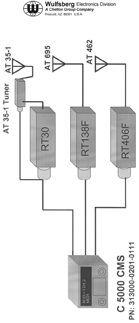
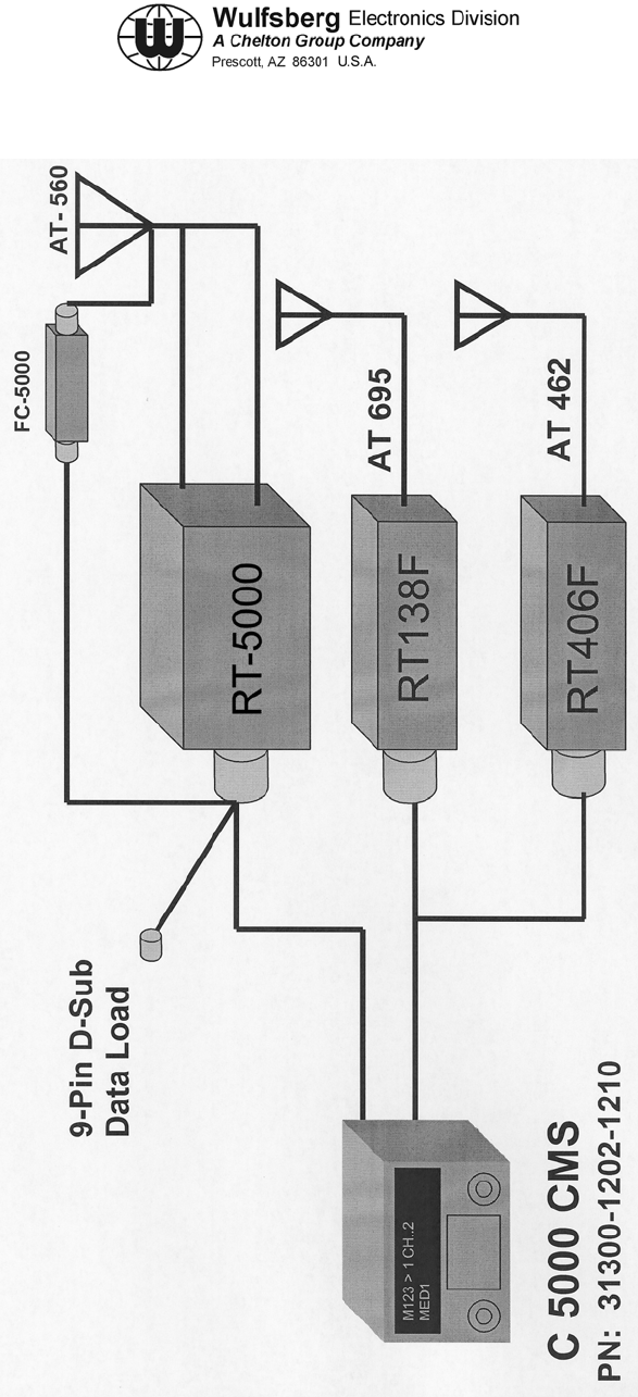
Figure B-1 shows the aircraft in its current configuration. Notice the C-5000 control head controls
three single band Wulfsberg transceivers, the RT-30, RT-138F, and RT-406F. Since the 29.7-50
MHz band is rarely used, it has been decided that the RT-30 can be removed and replaced by the
RT-5000. The RT-5000 covers 29.7-960 MHz and thus can perform all the functions of the RT-30
plus can be the additional radio in a relay along with the RT-138F or RT-406F(e.g. body wire relay).
In addition, it allows for a backup for the VHF-AM and UHF-AM radios already in the aircraft. Also,
the RT-5000 has the capability of communicating on the 800 MHz "Community" channels. These are
special frequencies set up in every trunking system for the purpose of communicating with non-
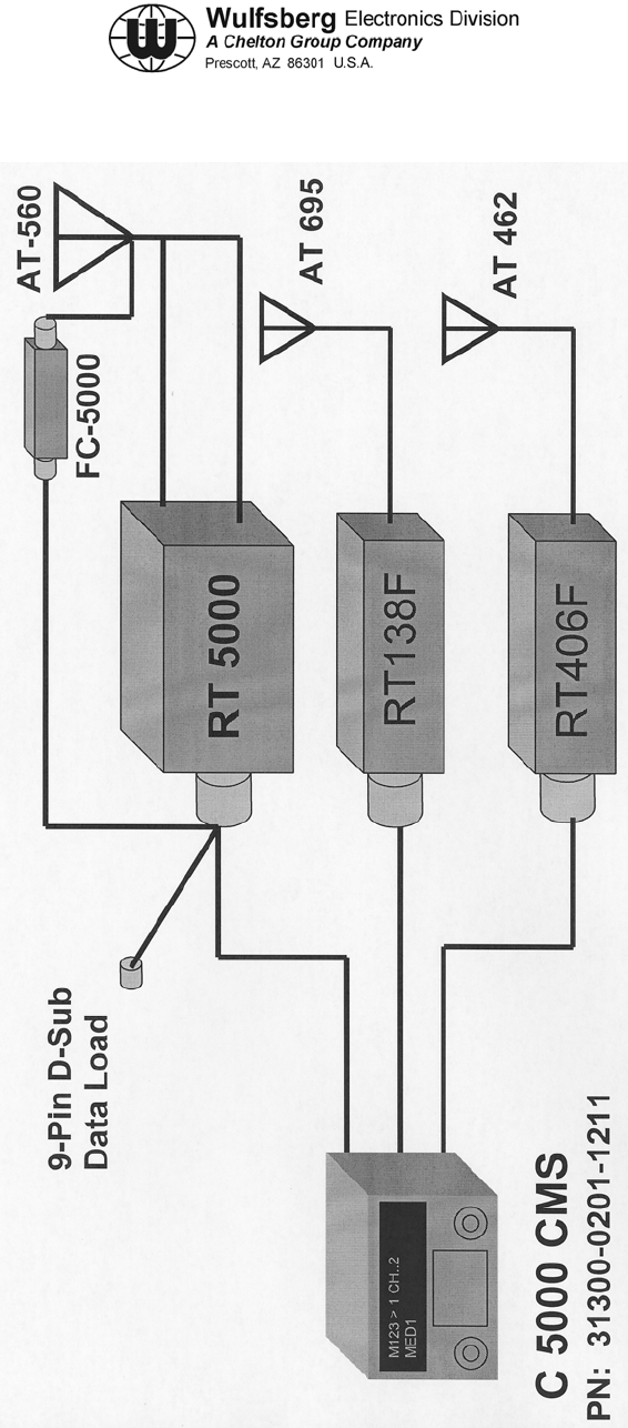
trunking radios. In this paper, this system is labeled "Configuration #1" (See Figure B-2).
The federal government along with some state and local public service organizations are moving to
digital communication systems known as P25 (APCO-25). There are models of the RT-5000 that can
perform this digital modulation in the VHF 138-174 (Federal Government), UHF 403-470 (Federal &
State/Local), UHF 450-512 (State & Local), and 800 MHz band. However, the C-5000 that is used
with this model of radio is limited to controlling two transceiver systems. This system is labeled
"Configuration #2" (See Figure B-3). Notice that the RT-138F and RT-406F have been connected
in parallel with a special adapter cable Wulfsberg provides. This allows both radios to still available,
however when connected in this manner, only one of the two radios can be channeled at any given
time. The easiest way to think of this is that transceiver #2 is "Dual Band" radio, VHF and UHF.
Note: The operator can only monitor the RT-138F or the RT-406F at any one time - not both at the
same time.
To upgrade the aircraft, the user must first determine the Radio Configuration (#1 or #2) that will be
needed. Second, all components must be ordered from Wulfsberg. If a C-5000 or RT-5000 needs to
be upgraded, the units must be sent to Wulfsberg. Once the all the system components are
delivered, the operator must perform the installation per ARMY AWR instructions. Basically this
involves the following steps:
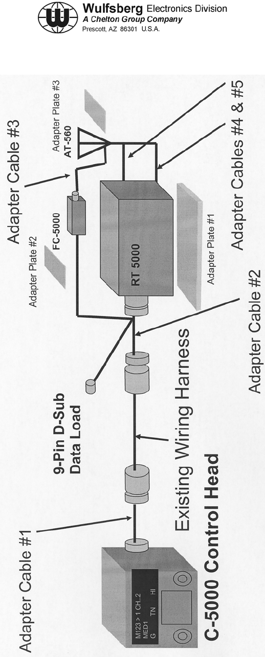
(1) Remove the RT-30 Transceiver, its mounting plate, antenna, and antenna tuner
(2) Install Adapter Cable #1
(3) Install the RT-5000 mounting tray and adapter plate. All holes lineup with existing holes of
the RT-30 mounting tray so no drilling should be required.
(4) Install the FC-5000 on the adapter plate and mount in the existing holes of the previously
removed RT-30 antenna tuner. No drilling should be required.

C-5000 COMMUNICATION MANAGEMENT CONTROLLER
INSTALLATION MANUAL
Page B-2 Publication No. 150-041118
Appendix B Rev. C
May 2006
(5) Mount the new AT-560 antenna where the old RT-30 antenna was. This does require some
drilling of holes (We're good but not that good).
(6) Run the two new coax cables from the radio to the antenna.
(7) Run the Antenna tuning cable from the FC-5000 to the AT-560.
(8) Install Adapter Cable #2.
(9) Configure and program the C-5000.
(10) Verify system performance via test equipment and/or flight testing.
C-5000 COMMUNICATION MANAGEMENT CONTROLLER
INSTALLATION MANUAL
Publication No. 150-041118 Page B-3
Rev. C Appendix B
May 2006
Figure B-1. Current Configuration
(Basic RT-5000)
C-5000 COMMUNICATION MANAGEMENT CONTROLLER
INSTALLATION MANUAL
Page B-4 Publication No. 150-041118
Appendix B Rev. C
May 2006
Figure B-2. Configuration #1
(Basic RT-5000)
C-5000 COMMUNICATION MANAGEMENT CONTROLLER
INSTALLATION MANUAL
Publication No. 150-041118 Page B-5
Rev. C Appendix B
May 2006
Figure B-3. Configuration #2
(VHF and/or UHF Digital RT-5000)
C-5000 COMMUNICATION MANAGEMENT CONTROLLER
INSTALLATION MANUAL
Page B-6 Publication No. 150-041118
Appendix B Rev. C
May 2006
Figure B-4. Adapter Cables & Plates
(Allows use of existing harness)
C-5000 COMMUNICATION MANAGEMENT CONTROLLER
INSTALLATION MANUAL
Publication No. 150-041118 Page B-7
Rev. C Appendix B
May 2006
2. Flexcomm I To Flexcomm II Adapter Kit / Installation Kit
Requires 1 ea of the following ten (10) items (see install instructions)
PART NUMBER DESCRIPTION
153-041054-01 Adapter Cable, Harness/Transceiver/Antenna Tuner
153-041055-01 Adapter Cable, C-5000 Parallel to Serial
153-041056-01 Adapter Cable, FC-5000 to AT-560
153-041057-01 Adapter Cable, Coax Antenna Cable RG-142
153-041058-01 Adapter Cable, Coax Antenna Cable RG-393
300-341192-01 Adapter Mounting Tray, Flexcomm I Transceiver to RT-5000
300-341193-01 Adapter Plate, Antenna Mounting
300-341194-01 Adapter Plate, FC-35 to FC-5000
D037000Y00 Connector Backshells
124-041326-01 Adapter Cable, Single to Dual, Flexcomm I
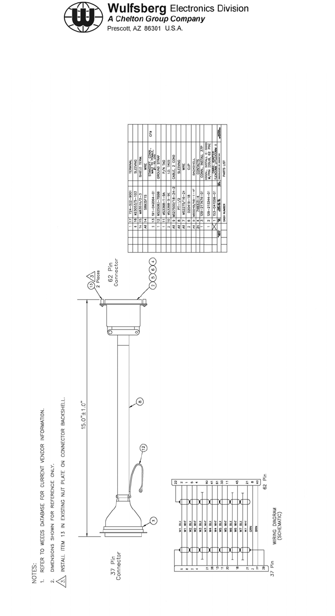
C-5000 COMMUNICATION MANAGEMENT CONTROLLER
INSTALLATION MANUAL
Page B-8 Publication No. 150-041118
Appendix B Rev. C
May 2006
Figure B-5. FLEXCOMM I / FLEXCOMM II Cable Adapter (Sheet 1 of 1)
Dwg No. 153-041056, Rev C
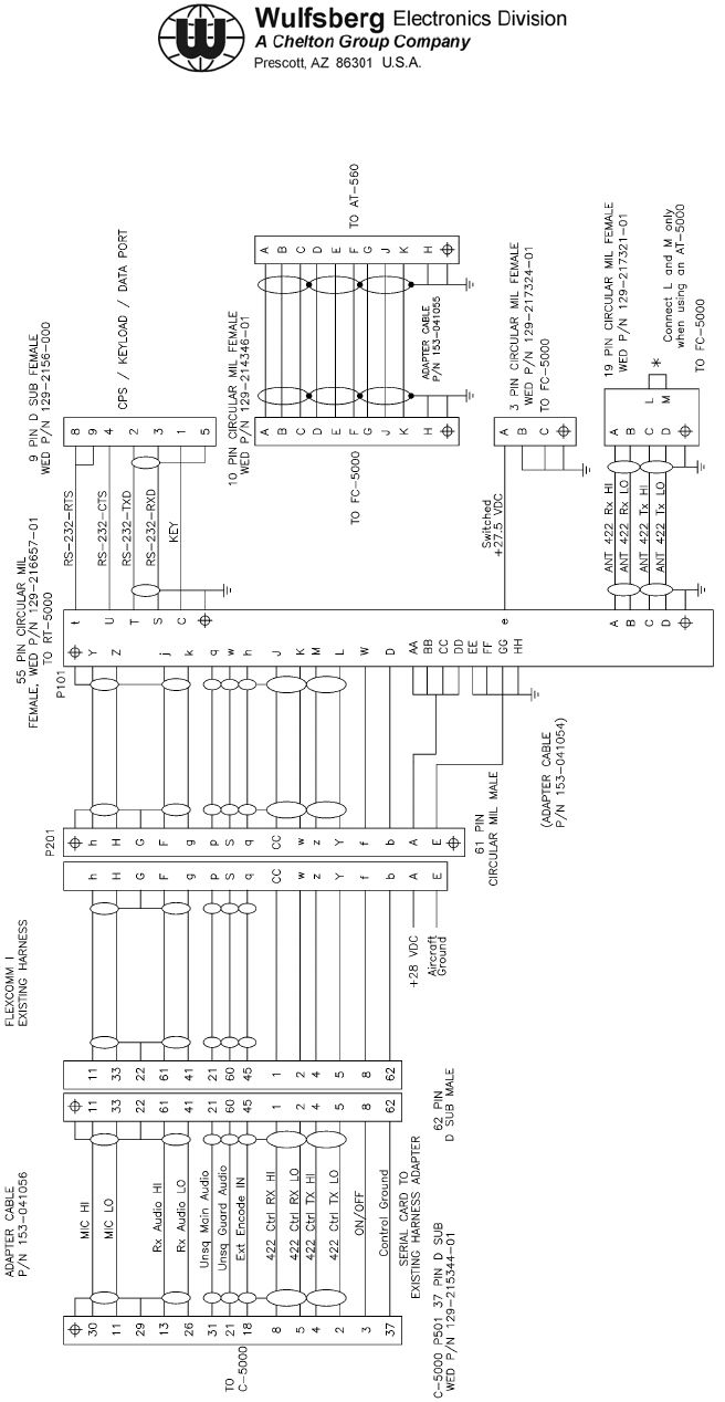
C-5000 COMMUNICATION MANAGEMENT CONTROLLER
INSTALLATION MANUAL
Publication No. 150-041118 Page B-9
Rev. C Appendix B
May 2006
Figure B-6. Installation Wiring Diagram
FLEXCOMM I / FLEXCOMM II Cable Adapters (Sheet 1 of 1)
Dwg No. 152-241316, Rev B
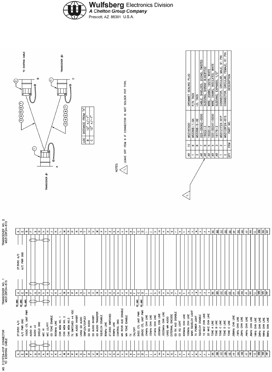
C-5000 COMMUNICATION MANAGEMENT CONTROLLER
INSTALLATION MANUAL
Page B-10 Publication No. 150-041118
Appendix B Rev. C
May 2006
Figure B-7. Cable Assembly
FLEXCOMM I Single to Dual Cable Adapter (Sheet 1 of 1)
Dwg No. 124-041326, Rev C