Wulfsberg Electronics Division RT-5000A VHF/ UHF Tactical Transeiver User Manual PRINTING INSTRUCTIONS
Wulfsberg Electronics Division VHF/ UHF Tactical Transeiver PRINTING INSTRUCTIONS
Contents
users manual 1
APPLICATION REVISIONS
REV
C
NEXT ASSEMBLY FINAL ASSEMBLY REV DESCRIPTION DATE APPROVED APPROVED
A Initial Release per DCN W1644 01-11-02 V Wallace S Hovelsrud
SH
1
B Revised per DCN W3784 12-2-04 V Wallace S H - CE
C Revised per DCN W5241
DWG. NO.
150-041118
THIS COVER SHEET IS FOR WULFSBERG ELECTRONICS INTERNAL USE. IT IS NOT TO
BE PUBLISHED WITH THE DOCUMENT IT DESCRIBES
THIS DOCUMENT CONTAINS PROPRIETARY INFORMATION OF WULFSBERG ELECTRONICS, A
CHELTON GROUP COMPANY, NEITHER RECEIPT NOR POSSESSION THEREOF CONFERS ANY RIGHT
TO REPRODUCE OR USE, OR DISCLOSE, IN WHOLE OR IN PART, ANY SUCH INFORMATION WITHOUT
WRITTEN AUTHORIZATION FROM WULFSBERG ELECTRONICS
Typed signatures indicate approval. Handwritten signature
approval of this document is on file at Wulfsberg Electronics,
Prescott, Arizona.
APPROVALS DATE
DRAWN
C Gregory
01-11-02
CHECKED
C Estes
01-11-02
INSTALLATION MANUAL
COMMUNICATIONS MANAGEMENT CONTROLLER
C-5000 (Digital Capable)
ENGINEER
S Hovelsrud
01-11-02 SIZE
A
CAGE CODE
1B7G3 DWG NO.
150-041118 REV
C
ISSUED
V Wallace
01-11-02 SCALE: NONE DO NOT SCALE DRAWING
This page intentionally left blank.

C-5000 COMMUNICATION MANAGEMENT CONTROLLER
INSTALLATION MANUAL
Page ii Publication No. 150-041118
Table of Contents Rev C
May 2006
Wulfsberg Electronics Division, located in Prescott, Arizona, designs and manufactures the
C-5000 Communication Management Controller
Wulfsberg Electronics Division makes no warranty, expressed or implied, with regard to this manual,
including but not limited to any implied warranties of merchantability, fitness for a particular purpose, and
non-infringement. In addition, Wulfsberg Electronics Division makes no warranty with regard to the
documentation or data contained herein. Wulfsberg Electronics Division is not liable in the event of
incidental, special, consequential, or any other damages in connection with or arising from furnishing,
performance, or use of this manual.
Reproduction of this publication or any portion thereof by any means is prohibited. For further information
contact Sales, Wulfsberg Electronics Division, 6400 Wilkinson Drive, Prescott, Arizona, 86301.
Telephone: (928) 708-1500.
Information in this manual is subject to change without notice.
© 2001 Wulfsberg Electronics Division. All rights reserved
C-5000 is a trademark of Wulfsberg Electronics Division.
PROPRIETARY NOTICE
This document contains proprietary information and such information may not be disclosed to others for
any purpose, nor used for manufacturing purposes without written permission from Wulfsberg Electronics
Division.

C-5000 COMMUNICATION MANAGEMENT CONTROLLER
INSTALLATION MANUAL
Publication No. 150-041118 Page iii
Rev C Table of Contents
May 2006
Record of Revisions
Rev
No. Rev
Date Date
Inserted
By Rev
No. Rev
Date Date
Inserted
By
A 1/2002
B 11/2004
C 5/2006

C-5000 COMMUNICATION MANAGEMENT CONTROLLER
INSTALLATION MANUAL
Page iv Publication No. 150-041118
Table of Contents Rev C
May 2006
Record of Revisions
Rev
No. Rev
Date Date
Inserted
By Rev
No. Rev
Date Date
Inserted
By

C-5000 COMMUNICATION MANAGEMENT CONTROLLER
INSTALLATION MANUAL
Publication No. 150-041118 Page v
Rev C Table of Contents
May 2006
TABLE OF CONTENTS
Page
SECTION 1 - INTRODUCTION
1. Components................................................................................................................1-1
A. Communication Management Controller .......................................................1-1
B. FLEXCOMM II................................................................................................1-1
C. FLEXCOMM I.................................................................................................1-2
D. Part Numbering..............................................................................................1-3
SECTION 2 - SYSTEM INSTALLATION
1. General........................................................................................................................2-1
2. Sample Systems .........................................................................................................2-1
3. Component Specifications ..........................................................................................2-3
A. C-5000 Communication Management Controller...........................................2-3
B. FLEXCOMM II (RT-5000) ..............................................................................2-4
C. RT-5000 Antennas.........................................................................................2-5
D. FLEXCOMM I.................................................................................................2-9
E. Miscellaneous Data Loading Cables and Software .......................................2-9
SECTION 3 – MECHANICAL INSTALLATION
1. General........................................................................................................................3-1
2. Unpacking and Inspecting Equipment ........................................................................3-1
3. General Installation Requirements..............................................................................3-2
A. Component Weights.......................................................................................3-2
4. Installation of Multipin Crimp Connectors ...................................................................3-3
A. Contacts and Crimp Tool Information ............................................................3-3
B. Contacts and Insertion/Removal Tool Manufacturer Name and Address .....3-3
5. Installation of C-5000 ..................................................................................................3-3
6. Installation of RT-5000................................................................................................3-3
Continues…….

C-5000 COMMUNICATION MANAGEMENT CONTROLLER
INSTALLATION MANUAL
Page vi Publication No. 150-041118
Table of Contents Rev C
May 2006
TABLE OF CONTENTS (cont’d)
Page
SECTION 3 – MECHANICAL INSTALLATION (cont’d)
7. Installation of Antennas...............................................................................................3-4
A. AT-560 / AT-5000...........................................................................................3-4
B. FC-5000 .........................................................................................................3-4
C. AT-160 and AT-150........................................................................................3-4
D. AT-550............................................................................................................3-4
E. FC-550 ...........................................................................................................3-4
F. AT-50 AND AT-51..........................................................................................3-5
G. FC-50 .............................................................................................................3-5
H. AT-400............................................................................................................3-5
I. AT-140............................................................................................................3-5
SECTION 4 - ELECTRICAL INSTALLATION
1. General........................................................................................................................4-1
2. Wiring Considerations .................................................................................................4-1
A. C-5000 System Interface Connector, P500 ...................................................4-2
B. C-5000 Transceiver Interface to RT-5000 ...................................................4-17
C. C-5000 RS-2332 Data Load Connector P503 .............................................4-22
D. RT-5000 Transceiver Installation ................................................................4-23
E. RT-5000 Transceiver Installation .................................................................4-30
F. C-5000 Communication Management Controller Installation ......................4-75
G. C-5000 Transceiver Interface, RT-9600, RT-9600F, RT-7200....................4-91
H. Special Options ..........................................................................................4-101
SECTION 5 – CONFIGURATION AND PROGRAMMING
1. General........................................................................................................................5-1
SECTION 6 – SYSTEM VERIFICATION PROCEDURE
1. General........................................................................................................................6-1

C-5000 COMMUNICATION MANAGEMENT CONTROLLER
INSTALLATION MANUAL
Publication No. 150-041118 Page vii
Rev C Table of Contents
May 2006
TABLE OF CONTENTS (cont’d)
Page
SECTION 7 – SYSTEM CHECKOUT
1. General........................................................................................................................7-1
A. Terms, Definitions and Limitations.................................................................7-1
2. System Checkout ........................................................................................................7-1
A. General...........................................................................................................7-1
B. Checkout Setup..............................................................................................7-2
C. Checklist.........................................................................................................7-2
D. Checkout Procedure ......................................................................................7-2
3. Transmitter Tests ........................................................................................................7-4
A. General...........................................................................................................7-4
B. Receiver Verification ......................................................................................7-4
C. Encryption Verification ...................................................................................7-5
4. Installation Checkout Data Tables and Checklist........................................................7-6
APPENDIX A:
Continuous Airworthiness Instructions For Flexcomm II System............................... A-1
APPENDIX B:
1. RAID OH-58 Upgrade Overview and Cabling Information......................................... B-1
A. Scope................................................................................................................. B-1
B. Modification Process.......................................................................................... B-1
2. Flexcomm I to Flexcomm II Adapter Kit / Installation Kit ........................................... B-7

C-5000 COMMUNICATION MANAGEMENT CONTROLLER
INSTALLATION MANUAL
Page viii Publication No. 150-041118
Table of Contents Rev C
May 2006
LIST OF FIGURES
FIGURE PAGE
1-1 C-5000 Part Numbering......................................................................................1-3
2-1 Single RT-5000 with Active Antenna ..................................................................2-1
2-2 Single RT-5000 with Passive Antenna................................................................2-1
2-3 Dual RT-5000 with Dual Mic/Headset.................................................................2-1
2-4 Dual Transceiver, RT-5000 and Flexcomm I......................................................2-2
2-5 Dual Transceiver, RT-5000 and Parallel Flexcomm I Transceivers ...................2-2
2-6 Dual Transceiver with External Encryption .........................................................2-2
3-1 C-5000 Envelope Drawing..................................................................................3-8
3-2 RT-5000 Envelope Drawing................................................................................3-9
3-3 RT-5000 Tray Horizontal Mount........................................................................3-10
3-4 RT-5000 Tray Vertical Mount............................................................................3-11
3-5 AT-560 Envelope Drawing................................................................................3-12
3-6 AT-160 Envelope Drawing................................................................................3-13
3-7 AT-5000 Envelope Drawing..............................................................................3-14
3-8 AT-550 Envelope Drawing................................................................................3-15
3-9 AT-150 Envelope Drawing................................................................................3-16
3-10 AT-50 Envelope Drawing..................................................................................3-17
3-11 AT-51 Envelope Drawing..................................................................................3-18
3-12 AT-140 Envelope Drawing................................................................................3-19
3-13 AT-400 Envelope Drawing................................................................................3-20
3-14 FC-50 Envelope Drawing..................................................................................3-21
3-15 FC-5000 Envelope Drawing..............................................................................3-22
3-16 FC-550 Envelope Drawing................................................................................3-23
3-17 FC-550 Envelope Drawing................................................................................3-24
4-1 Rear View of C-5000...........................................................................................4-1
4-2 P500 Connector ..................................................................................................4-2
4-3 C-5000 Standard Installation Wiring Diagram ..................................................4-11
4-4 P501/P502 Connectors.....................................................................................4-17
4-5 P503 Connector ................................................................................................4-22
4-6 Connector J101 (Digital Capable).....................................................................4-23
4-7 Connector J101 (Analog)..................................................................................4-30
4-8 FC-50 / FC-550 / FC-5000 Connector J1..........................................................4-37

C-5000 COMMUNICATION MANAGEMENT CONTROLLER
INSTALLATION MANUAL
Publication No. 150-041118 Page ix
Rev C Table of Contents
May 2006
LIST OF FIGURES (cont’d)
FIGURE PAGE
4-9 FC-50 / FC-550 / FC-5000 Connector J2..........................................................4-38
4-10 FC-50 / FC-550 / FC-5000 Connector J3..........................................................4-39
4-11 Flexcomm II System Interconnect Drawing ......................................................4-41
4-12 C-5000 Transceiver (FLEXCOMM I) Connector P501 or P502........................4-75
4-13 FLEXCOMM I Transceivers Installation Wiring Diagram..................................4-81
4-14 Connector P501/P502.......................................................................................4-91
4-15 Installation Wiring Diagram, RT-9600, RT-9600F, RT-7200.............................4-95
4-16 Dual C-5000/RT-5000 with Take_Control Block Diagram..............................4-104
4-17 Cable Assembly, C-5000 Digital Interface ......................................................4-105
4-18 Cable Assembly, 8-Pin Mini Din with Cable....................................................4-109
4-19 Wiring Harness Diagram, KVL to RT-5000.....................................................4-111
B-1 Current Configuration (Basic RT-5000) ............................................................. B-3
B-2 Configuration #1 (Basic RT-5000) ..................................................................... B-4
B-3 Configuration #2 (VHF and/or UHF Digital RT-5000) ........................................ B-5
B-4 Adapter Cables and Plates ................................................................................ B-6
B-5 Flexcomm I / Flexcomm II Cable Adapter.......................................................... B-8
B-6 Installation Wiring Diagram Flexcomm I / Flexcomm II Cable Adapters............ B-9
B-7 Cable Assembly, Flexcomm I Single to Dual Cable Adapter........................... B-10
B-8 Cable, Transceiver Logic, Flexcomm I / Flexcomm II...................................... B-11
B-9 Cable, Antenna, Flexcomm I / Flexcomm II..................................................... B-12
B-10 Cable, Coax, Antenna (RG142), Flexcomm I / Flexcomm II ........................... B-13
B-11 Cable, Coax, Antenna (RG393), Flexcomm I / Flexcomm II ........................... B-14

C-5000 COMMUNICATION MANAGEMENT CONTROLLER
INSTALLATION MANUAL
Page x Publication No. 150-041118
Table of Contents Rev C
May 2006
LIST OF TABLES
TABLE PAGE
1-1 RT-5000 Part Numbers.......................................................................................1-3
1-2 FLEXCOMM II Antenna Part Numbers...............................................................1-7
1-3 RT-30 Part Numbers...........................................................................................1-7
1-4 RT-118 Part Numbers.........................................................................................1-7
1-5 RT-138 Part Numbers.........................................................................................1-7
1-6 RT-138F Part Numbers.......................................................................................1-8
1-7 RT-406F Part Numbers.......................................................................................1-9
1-8 RT-450 Part Numbers.........................................................................................1-9
1-9 RT-7200 Part Numbers.....................................................................................1-10
1-10 RT-9600 Part Numbers.....................................................................................1-10
1-11 RT-9600F Part Numbers...................................................................................1-11
2-1 System Power Requirements .............................................................................2-3
3-1 Component Weights............................................................................................3-2
4-1 System Interface Connector P500 Pin Names ...................................................4-3
4-2 C-5000 Transceiver (RT-5000) Connector P501,:502 Pin Names...................4-17
4-3 C-5000 RS-232 Data Load Connector P503 ....................................................4-22
4-4 RT-5000 Transceiver (Digital Capable) Connector J101 Pin Names...............4-24
4-5 RT-5000 Transceiver (Analog) Connector J101 Pin Names ............................4-31
4-6 C-5000 Transceiver (FLEXCOMM I) Connector P501 or P502........................4-76
4-7 C-5000 Transceiver (RT-9600(F)/7200) Connector P50X
(P501, P502 or P503) .......................................................................................4-92
4-8 Connectors Used ............................................................................................4-113
7-1 RT-30 Transceiver Test Frequencies ...............................................................7-10
7-2 RT-138(F) Transceiver Test Frequencies.........................................................7-10
7-3 RT-406F Transceiver Test Frequencies...........................................................7-10
7-4 RT-450 Transceiver Test Frequencies .............................................................7-11
7-5 RT-5000 Transceiver Lo Split (29.7 to 399.999 MHz) Test Frequencies .........7-11
7-6 RT-5000 Transceiver Hi Split (400 MHz to 959.999) Test Frequencies...........7-11
7-7 RT-30 Transceiver Test Frequencies ...............................................................7-12
7-8 RT-138(F) Transceiver Test Frequencies.........................................................7-12
7-9 RT-406F Transceiver Test Frequencies...........................................................7-12
7-10 RT-450 Transceiver Test Frequencies .............................................................7-13
7-11 RT-5000 Transceiver Lo Split (29.7 to 399.999 MHz) Test ..............................7-13
7-12 RT-5000 Transceiver Hi Split (400 MHz to 959.999) Test Frequencies...........7-13
C-5000 COMMUNICATION MANAGEMENT CONTROLLER
INSTALLATION MANUAL
Publication No. 150-041118 Page 1-1
Rev C Section 1 - Introduction
May 2006
SECTION 1 - INTRODUCTION
IMPORTANT
This manual contains information pertaining to the installation of the C-5000
Communication Management Controller with FLEXCOMM II and FLEXCOMM I.
FLEXCOMM II consists of the RT-5000 Transceiver, appropriate antennas, and optional
equipment as required. FLEXCOMM I consists of the RT-9600 Transceiver, RT-9600F
Transceiver, RT-7200 Transceiver, and optional combinations of up to three of the
following FLEXCOMM Transceivers: RT-30, RT-118, RT-138(F), RT-406F, RT-450,
appropriate antennas, and optional equipment as required. The C-5000 can also
interface with combined applications of FLEXCOMM II and FLEXCOMM I, i.e., a hybrid
RT System configuration that consists of both RT-5000 and FLEXCOMM I Transceivers.
1. Components
The following components can be installed:
A. Communication Management Controller
C-5000 PN 31300-1X02-XXXX (See Figure 1-1)
B. FLEXCOMM II
(1) Transceivers
RT-5000 PN 400-015525-XXXX (See Table 1-1)
(2) Antennas Systems (Refer to Table 1-2)
AT-560 PN 121-040130-XX
AT-160 PN 121-040129-01
AT-5000 PN 121-040045-01
AT-550 PN 121-017850-01
AT-150 PN 153-017822-01
AT-50 PN 121-016587-01
AT-51 PN 121-016796-01
AT-140 PN 121-016584-01
AT-400 PN 121-16821-01
FC-50 Logic Converter PN 153-016586-01
FC-5000 Logic Converter PN 153-040047-01

RT-5000 COMMUNICATION MANAGEMENT CONTROLLER
INSTALLATION MANUAL
Page 1-2 Publication No. 150-041118
Section 1 - Introduction Rev C
May 2006
FC-550 Logic Converter PN 153-017851
(3) RT-5000 Mounting Trays
Vertical Mounting Tray PN 300-316605-01
Horizontal Mounting Tray PN 300-316835-01
C. FLEXCOMM I
(1) Transceivers
RT-30 PN 400-0098-XXX (See Table 1-3)
RT-118 PN 400-0119-XXX (See Table 1-4)
RT-138 PN 400-0102-XXX (See Table 1-5)
RT-138F PN 400-014525-XX/5X (See Table 1-6)
RT-406F PN 400-012785-XX/5X (See Table 1-7)
RT-450 PN 400-0103-XXX (See Table 1-8)
RT-7200 PN 400-0087-XXX (See Table 1-9)
RT-9600 PN 400-0052-XXX (See Table 1-10)
RT-9600F PN 400-0140-XXXX (See Table 1-11)
(2) Antennas
AT-35 System PN 121-014235-XX
AT-270 PN 121-0002-000
AT-461 PN 121-0011-000
AT-462 PN 121-014378-01
AT-695 PN 121-0019-000
AT-960 PN 121-0010-000
Note: Refer to the following for information on FLEXCOMM I antennas and
installation:
a FLEXCOMM I Installation Manual, WED Manual No. 150-040011-000, for
information on FLEXCOMM Antennas.
b WED Manual No. 150-0061-000 for information on RT-9600 and RT-7200
Antennas.
C-5000 COMMUNICATION MANAGEMENT CONTROLLER
INSTALLATION MANUAL
Publication No. 150-041118 Page 1-3
Rev C Section 1 - Introduction
May 2006
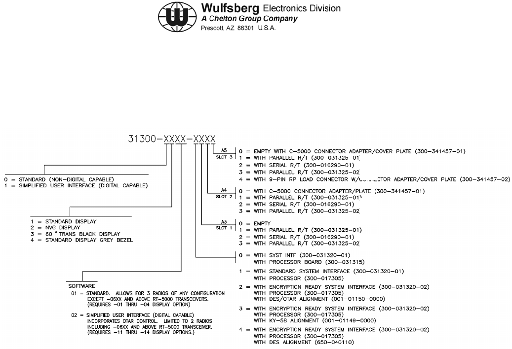
D. Part Numbering
The C-5000's basic unit part number 31300-XXXX-XXXX is configured as follows:
Figure 1-1. C-5000 Part Numbering
(Ref Dwg No. 400-031300, Rev AM)
Note: Processor board PN 300-031315 can only be used with Parallel R/T board
PN 300-031325. Processor board PN 300-017305 can be used with Parallel
R/T PN 300-031325 and Serial R/T board PN 300-016290.
The installation and operation of the Frequency Agile C-5000 Control Unit is
limited to aircraft installations per FCC Rules and Regulations, Part 90, Section
90.423 and 90.203(h). A non-frequency agile C-5000 is available for other than
aircraft installations and is in compliance with FCC Rules and Regulations
90.203(g).

RT-5000 COMMUNICATION MANAGEMENT CONTROLLER
INSTALLATION MANUAL
Page 1-4 Publication No. 150-041118
Section 1 - Introduction Rev C
May 2006
Table 1-1. RT-5000 Part Numbers
Part Number Analog Description
400-015525-0101 Standard Transceiver w/o Guard
400-015525-0201 Transceiver, 30-50 MHz Guard
400-015525-0301 Transceiver, 138-174 MHz Guard
400-015525-0401 Transceiver, 406-512 MHz Guard
400-015525-0501 Transceiver w/Synthesized Guard
XTS-3000 Description
400-015525-0611 Transceiver, D.E.S. Encrypted VHF 138-174 MHz MTM Guard Receiver
400-015525-0711 Transceiver, VHF 138 MHz MTM Guard Receiver
400-015525-0811 Transceiver, D.E.S. Encrypted UHF403 MHz MTM Guard Receiver
400-015525-0911 Transceiver, UHF403 MHz MTM Guard Receiver
400-015525-1011 Transceiver, D.E.S. Encrypted UHF450-520 MHz MTM Guard Receiver
400-015525-1111 Transceiver, UHF520 MHz MTM Guard Receiver
400-015525-1211 Transceiver, D.E.S. Encrypted UHF800 Trunk MHz MTM Guard Receiver
400-015525-1311 Transceiver, UHF800 MHz MTM Guard Receiver
400-015525-1411 Transceiver, D.E.S. Encrypted VHF138 MHz MTM Guard Receiver and
UHF800 MHz MTM Guard Receiver
400-015525-1511 Transceiver, VHF138 MHz MTM Guard Receiver and UHF800 MHz MTM
Guard Receiver
400-015525-1611 Transceiver, D.E.S. Encrypted VHF138 MHz MTM Guard Receiver and D.E.S.
Encrypted UHF800 MHz MTM Guard Receiver
400-015525-1711 Transceiver, VHF138 MHz MTM Guard Receiver and D.E.S. Encrypted
UHF800 MHz MTM Guard Receiver
400-015525-1811 Transceiver, D.E.S. Encrypted VHF138 MHz MTM Guard Receiver and
UHF520 MHz MTM Guard Receiver
400-015525-1911 Transceiver, VHF138 MHz MTM Guard Receiver and UHF520 MHz MTM
Guard Receiver
400-015525-2011 Transceiver, D.E.S. Encrypted VHF138 MHz MTM Guard Receiver and D.E.S.
Encrypted UHF520 MHz MTM Guard Receiver
400-015525-2111 Transceiver, VHF138 MHz MTM Guard Receiver and D.E.S. Encrypted
UHF520 MHz MTM Guard Receiver
400-015525-2211 Transceiver, D.E.S. Encrypted VHF138 MHz MTM Guard Receiver and
UHF403 MHz MTM Guard Receiver
400-015525-2311 Transceiver, VHF138 MHz MTM Guard Receiver and UHF403 MHz MTM
Guard Receiver

C-5000 COMMUNICATION MANAGEMENT CONTROLLER
INSTALLATION MANUAL
Publication No. 150-041118 Page 1-5
Rev C Section 1 - Introduction
May 2006
Table 1-1. RT-5000 Part Numbers (cont’d)
Part Number XTS-3000 Description
400-015525-2411 Transceiver, D.E.S. Encrypted VHF138 MHz MTM Guard Receiver and D.E.S.
Encrypted UHF403 MHz MTM Guard Receiver
400-015525-2511 Transceiver, VHF138 MHz MTM Guard Receiver and D.E.S. Encrypted
UHF403 MHz MTM Guard Receiver
400-015525-2611 Transceiver, DVI-XL UHF520 MHz MTM Guard Receiver
400-015525-2711 Transceiver, DVI-XL UHF800 MHz MTM Guard Receiver
400-015525-2811 Transceiver, 138 MHz w/D.E.S. MTM Guard Receiver
400-015525-2911 Transceiver, 138 MHz w/D.V.P. MTM Guard Receiver
400-015525-3011 Transceiver, 800 MHz w/D.E.S, MTM Guard Receiver
400-015525-3111 Transceiver, 800 MHz w/MTM Guard Receiver
400-015525-3211 Transceiver, 403 MHz w/D.E.S., MTM Guard Receiver
400-015525-3311 Transceiver, 138 MHz w/D.E.S., MTM Guard Receiver and A.E.S.
400-015525-3411 Transceiver, 138 MHz w/Smartnet/D.E.S., 520 MHz/ Smartzone/A.E.S/D.E.S.,
MTM Guard Receiver
400-015525-3511 Transceiver, 138 MHz, Smartnet w/A.E.S./D.E.S., 403 MHz Smartnes
w/A.E.S./D.E.S., P-25 MTM Guard
Part Number XTS-5000 Description
400-015525-5011 Transceiver, VHF (136-174 MHz), P-25 TRUNKING, ENCRYPTION AND UHF
(764-870 MHz), P-25 TRUNKING, ENCRUPTION
400-015525-5111 Transceiver, VHF (136-174 MHz), P-25 TRUNKING, ENCRYPTION AND UHF
(380-470 MHz), P-25 TRUNKING, ENCRYPTION
400-015525-5211 Transceiver, VHF (136-174 MHz), P-25 TRUNKING, ENCRYPTION AND UHF
(450-520 MHz), P-25 TRUNKING, ENCRYPTION
400-015525-5311 Transceiver, UHF (764-870 MHz), P-25 TRUNKING, ENCRYPTION
400-015525-5411 Transceiver, UHF (380-470 MHz), P-25 TRUNKING, ENCRYPTION
400-015525-5511 Transceiver, UHF (450-520 MHz), P-25 TRUNKING, ENCRYPTION
400-015525-5611 Transceiver, VHF (136-174 MHz), P-25 TRUNKING, ENCRYPTION

RT-5000 COMMUNICATION MANAGEMENT CONTROLLER
INSTALLATION MANUAL
Page 1-6 Publication No. 150-041118
Section 1 - Introduction Rev C
May 2006
Table 1-2. FLEXCOMM II Antenna Part Numbers
Part Number Antenna Description
121-040130-01 AT-560 -- 29.7 - 960 MHz 9.5” Tuned Multiband White
121-040130-02 AT-560 -- 29.7 - 960 MHz 9.5” Tuned Multiband Black
121-040129-01 AT-160 -- 29.7 – 960 MHz 9.5” Passive Multiband
121-040045-01 AT-5000 -- 29.7 – 960 MHz 5.5” (FC-5000 Req) White
121-040045-02 AT-5000 -- 29.7 – 960 MHz 5.5” (FC-5000 Req) Black
121-017850-01 AT-550 -- 29.7 – 960 MHz (FC-550 Req) White
153-017822-01 AT-150 -- 29.7 – 960 MHz (poor 30-88 MHz) White
121-016587-01 AT-50 -- 29.7 - 400MHz Autotuned Blade White
121-016796-01 AT-51 -- 29.7 - 400MHz Autotuned Blade White
121-016584-01 AT-140 -- 29.7MHz - 400MHz Blade White
121-016821-01 AT-400 -- 400MHz - 960MHZ Jet Blade White
153-016586-01 FC-50 Logic Converter -- Antenna Tuner for AT-50/51
153-040047-01 FC-5000 -- Antenna Tuner for AT-5000 and AT-560

C-5000 COMMUNICATION MANAGEMENT CONTROLLER
INSTALLATION MANUAL
Publication No. 150-041118 Page 1-7
Rev C Section 1 - Introduction
May 2006
Table 1-2. FLEXCOMM II Antenna Part Numbers (cont’d)
Part Number Antenna Description
153-017851 FC-550 Logic Converter
146-016958-01 Gasket, AT-400
146-014960-01 Gasket, AT-51
146-014959-01 Gasket, AT-50
Table 1-3. RT-30 Part Numbers
Part Number RT-30 Description
400-0098-000 Transceiver, FLEXCOMM Lo Band VHF, 29.70-49.99 MHz.
400-0098-001 Transceiver, FLEXCOMM Lo Band VHF, 29.70 - 49.99 MHz, with Guard
Receiver
400-0098-002 Transceiver, FLEXCOMM Lo Band VHF, 29.70 - 49.99 MHz, with Guard
Receiver and Guard Receiver CTCSS Tones.
Table 1-4. RT-118 Part Numbers
Part Number RT-118 Description
400-0119-000 Transceiver, FLEXCOMM VHF-AM Band 118.000 - 137.975 MHz,
Standard Receiver IF Bandwidth
400-0119-001 Transceiver, FLEXCOMM VHF-AM Band 118.000 - 137.975 MHz,
Wide Receiver IF Bandwidth
Table 1-5. RT-138 Part Numbers
Part Number RT-138 Description
400-0102-000 Transceiver, FLEXCOMM Hi Band VHF, 138.0000 - 173.9975 MHz
400-0102-001 Transceiver, FLEXCOMM Hi Band VHF, 138.0000 - 173.9975 MHz, with
Guard Receiver.
400-0102-002 Transceiver, FLEXCOMM Hi Band VHF, 138.0000 - 173.9975 MHz, with
Guard Receiver and Guard Receiver CTCSS Tones
400-0102-003 Transceiver, FLEXCOMM Hi Band VHF, 138.0000 - 173.9975 MHz, with
increased sensitivity (precludes Guard).

RT-5000 COMMUNICATION MANAGEMENT CONTROLLER
INSTALLATION MANUAL
Page 1-8 Publication No. 150-041118
Section 1 - Introduction Rev C
May 2006
Table 1-6. RT-138F Part Numbers
Part Number RT-138F Description
400-014525-00 Transceiver, FLEXCOMM Hi Band VHF, 138.0000-173.9975 MHz.
400-014525-01 Transceiver, FLEXCOMM Hi Band VHF, 138.0000 - 173.9975 MHz, with
Guard Receiver.
400-014525-02 Transceiver, FLEXCOMM Hi Band VHF, 138.0000 - 173.9975MHz, with Guard
Receiver and Guard Receiver CTCSS Tones.
400-014525-03 Transceiver, FLEXCOMM Hi Band VHF, 138.0000 - 173.9975 MHz, with
increased sensitivity (precludes Guard).
400-014525-50 Transceiver, FLEXCOMM Hi Band VHF, 138.0000 - 173.9975 MHz, Voice
Encryption interface compatible.
400-014525-51 Transceiver, FLEXCOMM Hi Band VHF, 138.0000 - 173.9975 MHz, with
Guard Receiver, Voice Encryption interface compatible.
400-014525-52 Transceiver, FLEXCOMM Hi Band VHF, 138.0000 - 173.9975 MHz, with
Guard Receiver, Guard Receiver CTCSS Tones and Voice Encryption
interface compatible.
400-014525-53 Transceiver, FLEXCOMM Hi Band VHF, 138.0000 - 173.9975 MHz, with
increased sensitivity and Voice Encryption interface compatible (precludes
Guard).
Note: All RT-138F units are compatible with Voice Encryption systems utilizing Non Return to
Zero (NRZ) modulation at a data rate of 12 Kbit/sec or less. The -5X units are
specifically wired to readily interface with Motorola and General Electric encryption
modules. Additionally, all RT-138F units are compatible with Digital Coded Squelch
Systems (Motorola Digital Private Line and GE Digital Channel Guard).

C-5000 COMMUNICATION MANAGEMENT CONTROLLER
INSTALLATION MANUAL
Publication No. 150-041118 Page 1-9
Rev C Section 1 - Introduction
May 2006
Table 1-7. RT-406F Part Numbers
Part Number RT-406F Description
400-012785-00 Transceiver, FLEXCOMM UHF Band, 406.0000 511.9875 MHz.
400-012785-01 Transceiver, FLEXCOMM UHF Band, 406-0000 511.9875 MHz, with Guard
Receiver.
400-012785-02 Transceiver, FLEXCOMM UHF Band, 406.0000 511.9875 MHz, with Guard
Receiver and Guard Receiver CTCSS Tones.
400-012785-03 Transceiver, FLEXCOMM UHF Band, 406.0000 511.9875 MHz, with increased
sensitivity (precludes Guard).
400-012785-50 Transceiver, FLEXCOMM UHF Band, 406.0000 511.9875 MHz, Voice
Encryption interface compatible
400-012785-51 Transceiver, FLEXCOMM UHF Band, 406.0000 511.9875 MHz, with Guard
Receiver, Voice Encryption interface compatible
400-012785-52 Transceiver, FLEXCOMM UHF Band, 406.0000 511.9875 MHz, with Guard
Receiver, Guard Receiver CTCSS Tones and Voice Encryption interface
compatible
400-012785-53 Transceiver, FLEXCOMM UHF Band, 406.0000 511.9875 MHz, with increased
sensitivity and Voice Encryption interface compatible (precludes Guard).
Note: All RT-406F units are compatible with Voice Encryption systems utilizing Non Return to
Zero (NRZ) modulation at a data rate of 12 Kbit/sec or less. The -5X units are
specifically wired to readily interface with Motorola and General Electric encryption
modules. Additionally, all RT-406F units are compatible with Digital Coded Squelch
Systems (Motorola Digital Private Line and GE Digital Channel Guard).
Table 1-8. RT-450 Part Numbers
Part Number RT-450 Description
400-0103-000 Transceiver, FLEXCOMM UHF Band, 450.0000 - 469.9875 MHz.
400-0103-001 Transceiver, FLEXCOMM UHF Band, 450.0000 - 469.9875 MHz, with Guard
Receiver.
400-0103-002 Transceiver, FLEXCOMM UHF Band, 450.0000 - 469.9875 MHz, with Guard
Receiver and Guard Receiver CTCSS Tones.
400-0103-003 Transceiver, FLEXCOMM UHF Band, 450.0000 - 469.9875 MHz, with
increased sensitivity (precludes Guard).

RT-5000 COMMUNICATION MANAGEMENT CONTROLLER
INSTALLATION MANUAL
Page 1-10 Publication No. 150-041118
Section 1 - Introduction Rev C
May 2006
Table 1-9. RT-7200 Part Numbers
Part Number RT-7200 Description
400-0087-000 Transceiver, RT-7200 VHF HI-Band, 138.0000 - 173.995 MHz, 14/28 VDC,
100mW Audio, Recessed Connector.
400-0087-001 Transceiver, RT-7200 VHF HI-Band, 138.00 - 173.995 MHz, 14/28 VDC,
100mW Audio, Recessed Connector, with Guard Receiver.
400-0087-002 Transceiver, RT-7200 VHF HI-Band, 138.0000 - 173.995 MHz, 14/28 VDC,
100mW Audio, Recessed Connector, with CTCSS Tones.
400-0087-003 Transceiver, RT-7200 VHF HI-Band, 138.0000 - 173.995 MHz, 14/28 VDC,
100mW Audio, Recessed Connector, with Guard Receiver and CTCSS Tones.
Table 1-10. RT-9600 Part Numbers
Part Number RT-9600 Description
400-0052-002 Transceiver, RT-9600 VHF HI-Band, 150.0000 - 173.995 MHz, 14/28 VDC,
100 mW Audio, Protruding Connector
400-0052-005 Transceiver, RT-9600 VHF HI-Band, 150.0000 - 173.995 MHz, 14/28 VDC,
100 mW Audio, Protruding Connector, with Guard Receiver
400-0052-008 Transceiver, RT-9600 VHF HI-Band, 150.0000 - 173.995 MHz, 4/28 VDC,
100 mW Audio, Protruding Connector with CTCSS Tones
400-0052-011 Transceiver, RT-9600 VHF HI-Band, 150.0000 - 173.995 MHz, 14/28 VDC,
100 mW Audio, Protruding Connector, with Guard Receiver and CTCSS Tones
400-0052-024 Transceiver, RT-9600 VHF HI-Band, 150.0000 - 173.995 MHz, 14/28VDC,
100 mW Audio, Recessed Connector
400-0052-025 Transceiver, RT-9600 VHF HI-Band, 150.0000 - 173.995 MHz, 14/28 VDC,
100 mW Audio, Recessed Connector, with Guard Receiver
400-0052-026 Transceiver, RT-9600 VHF HI-Band, 150.0000 - 173.995 MHz, 14/28 VDC,
100 mW Audio, Recessed Connector, with CTCSS Tones
400-0052-027 Transceiver, RT-9600 VHF HI-Band, 150.0000 - 173.995 MHz, 14/28 VDC,
100 mW Audio, Recessed Connector, with Guard Receiver and CTCSS Tones

C-5000 COMMUNICATION MANAGEMENT CONTROLLER
INSTALLATION MANUAL
Publication No. 150-041118 Page 1-11
Rev C Section 1 - Introduction
May 2006
Table 1-11. RT-9600F Part Numbers
Part Number RT-9600F Description
400-0140-002 Transceiver, RT-9600F VHF HI-Band, 150.0000 - 173.995 MHz, 14/28 VDC,
100 mW Audio, Protruding Connector
400-0140-005 Transceiver, RT-9600F VHF HI-Band, 150.0000 - 173.995 MHz, 14/28 VDC,
100 mW Audio, Protruding Connector, with Guard Receiver
400-0140-008 Transceiver, RT-9600F VHF HI-Band, 150.0000 - 173.995 MHz, 14/28 VDC,
100 mW Audio, Protruding Connector with CTCSS Tones
400-0140-011 Transceiver, RT-9600F VHF HI-Band, 14/28 VDC, 100 mW Audio, Protruding
Connector, with Guard Receiver and CTCSS Tones
400-0140-024 Transceiver, RT-9600F VHF HI-Band, 150.0000 - 173.995 MHz, 14/28VDC,
100 mW Audio, Recessed Connector
400-0140-025 Transceiver, RT-9600F VHF HI-Band, 150.0000 - 173.995 MHz, 14/28 VDC,
100 mW Audio, Recessed Connector, with Guard Receiver
400-0140-026 Transceiver, RT-9600F VHF HI-Band, 150.0000 - 173.995 MHz, 14/28 VDC,
100 mW Audio, Recessed Connector, with CTCSS Tones
400-0140-027 Transceiver, RT-9600F VHF HI-Band, 150.0000 - 173.995 MHz, 14/28 VDC,
100 mW Audio, Recessed Connector, with Guard Receiver and CTCSS Tones
400-0140-052,
400-0140-152 Transceiver, RT-9600F VHF HI-Band, 150.0000 -173.995 MHz, 14/28 VDC,
100 mW Audio, Protruding Connector and Voice Encryption interface
compatible
400-0140-055,
400-0140-155 Transceiver, RT-9600F VHF HI-Band, 150.0000 - 173.995 MHz, 14/28 VDC,
100 mW Audio, Protruding Connector, and Voice Encryption interface
compatible
400-0140-058,
400-0140-158 Transceiver, RT-9600F VHF HI-Band, 150.0000 - 173.995 MHz, 14/28 VDC,
100 mW Audio, Protruding Connector with CTCSS Tones, and Voice
Encryption interface compatible
400-0140-061,
400-0140-1611 Transceiver, RT-9600F VHF HI-Band, 150.0000 - 173.995 MHz, 14/28 VDC,
100 mW Audio, Protruding Connector, with Guard Receiver and CTCSS
Tones, and Voice Encryption interface compatible
400-0140-074,
400-0140-174 Transceiver, RT-9600F VHF HI-Band, 150.0000 - 173.995 MHz, 14/28 VDC,
100 mW Audio, Recessed Connector, and Voice Encryption interface
compatible
400-0140-075,
400-0140-175 Transceiver, RT-9600F VHF HI-Band, 150.0000 - 173.995 MHz, 14/28 VDC,
100 mW Audio, Recessed Connector, with Guard Receiver, and Voice
Encryption interface compatible
continues…

RT-5000 COMMUNICATION MANAGEMENT CONTROLLER
INSTALLATION MANUAL
Page 1-12 Publication No. 150-041118
Section 1 - Introduction Rev C
May 2006
Table 1-11. RT-9600F Part Numbers (Cont’d)
Part Number RT-9600F Description
400-0140-076,
400-0140-176 Transceiver, RT-9600F VHF HI-Band, 150.0000 - 173.995 MHz, 14/28 VDC,
100 mW Audio, Recessed Connector, with CTCSS Tones, and Voice
Encryption interface compatible
400-0140-077,
400-0140-177 Transceiver, RT-9600F VHF HI-Band, 150.0000 - 173.995 MHz, 14/28 VDC,
100 mW Audio, Recessed Connector, with Guard Receiver and CTCSS
Tones, and Voice Encryption interface compatible
Note: All RT-9600F units are compatible with Voice Encryption systems utilizing Non Return to
Zero (NRZ) modulation at a data rate of 12 Kbit/sec or less. The -05X, -06X, and -07X
units are specifically wired to readily interface with Motorola encryption modules.
Additionally, all RT-9600F units are compatible with Digital Coded Squelch Systems
(Motorola Digital Private Line and GE Digital Channel Guard).
C-5000 COMMUNICATION MANAGEMENT CONTROLLER
INSTALLATION MANUAL
Publication No. 150-041118 Page 2-1
Rev C Section 2 – System Installation
May 2006
SECTION 2 - SYSTEM INSTALLATION
1. General
This section contains system specifications, interface information, and examples of typical system
configurations for the C-5000 Communication Management Controller installed with FLEXCOMM
II, FLEXCOMM I, or a configuration consisting of both FLEXCOMM II and FLEXCOMM I
transceivers. System power requirements are included in Table 2-1. Figures 2-1 through 2- 6
show generalized system interface diagrams.
2. Sample Systems
The following are examples of ways to configure your aircraft installation:
Figure 2-1. Single RT-5000 with Active Antenna
Figure 2-2. Single RT-5000 with Passive Antenna
ACTIVE OR PASSIVE
ANTENNA
ACTIVE OR PASSIVE
ANTENNA
Figure 2-3. Dual RT-5000 with Dual Mic/Headset
C-5000 COMMUNICATION MANAGEMENT CONTROLLER
INSTALLATION MANUAL
Page 2-2 Publication No. 150-041118
Section 2 – System Installation Rev C
May 2006
Figure 2-4. Dual Transceiver, RT-5000 and Flexcomm I
Figure 2-5. Dual Transceiver, RT-5000 and Parallel Flexcomm I Transceivers
Figure 2-6. Dual Transceiver with External Encryption

C-5000 COMMUNICATION MANAGEMENT CONTROLLER
INSTALLATION MANUAL
Publication No. 150-041118 Page 2-3
Rev C Section 2 – System Installation
May 2006
3. Component Specifications
COMPONENT POWER REQUIREMENTS
C-5000 VOLTAGE: 27.5 Vdc ± 20% Aircraft
CURRENT: 0.4 amps (typical)
1.3 amps (maximum external loading)
FLEXCOMM II
RT-5000 VOLTAGE: 27.5 VDC Aircraft
STANDBY: 1.7 amps
RECEIVE: 1.7 amps
TRANSMIT: 10.0 amps
FLEXCOMM I RT-30
RT-118
RT-138
RT-138F
RT-406F
RT-450
RT-9600
RT-9600F
RT-7200
Refer to FLEXCOMM I Transceiver System Installation
Manual, Manual Number 150-040011, for power
requirements.
Refer to VHF/FM Transceivers RT-7200, RT-9600,
AN/ARC-513(V) Installation /Operators Manual, Manual
Number 150-0061-000, for power requirements.
Table 2-1. System Power Requirements
A. C-5000 Communication Management Controller
Note: The installation and operation of the Frequency Agile C-5000 Control Unit is limited
to aircraft installations per FCC Rules and Regulations, Part 90, Section 90.423 and
90.203(h). A non-frequency agile C-5000 is available for other than aircraft
installations and is in compliance with FCC Rules and Regulations 90.203(g).
(1) Number of Channels: 350 programmable channels
(2) Temperature: -30° to + 60° C
(3) Panel Lighting: 5 Vdc, 5 Vac, or 28 Vdc
(4) Keypad Lighting: Type: Electro Luminescent (E.L.) Lighting
Color: Blue/white (standard)
Green NVG (optional

C-5000 COMMUNICATION MANAGEMENT CONTROLLER
INSTALLATION MANUAL
Page 2-4 Publication No. 150-041118
Section 2 – System Installation Rev C
May 2006
(5) Audio Output: Standard: 100 mV into 600 ohm load, shop adjustable
0.1 to 250 mW, 600 ohms
Unsquelched Audio: 0.5 VRMS/2k ohms, adjustable 0.1
to 1.5 V
(6) Audio Input Level: Std. Voice: 0.25 Vrms 150 ohm balanced pair, shop
adjustable 30 mV to 1.5 Vrms Narrowband: same as
voice, 2K single ended
(7) Microphone Interface: Carbon or equivalent
B. FLEXCOMM II (RT-5000)
(1) RT-5000 Transceiver
a) Tunability: 1.25 kHz Incremental Tuning Simplex/Semi-duplex.
b) Mode: FM/AM/P25/Trunking
c) Frequency Bands: 29.7-88 MHz (FM Band)
108-118 MHz (receive only)
118-156 MHz (AM Band)
138-174 MHz (FM Band)
220-225 MHz (AM/FM)
225-400 MHz (AM/FM)
FM:
400-512 MHz
512-806 MHz
806-960 MHz
P25 Options
136-174 MHz
380-470 MHz
403-470 MHz
450-520 MHz
764-870 MHz
806-870 MHz
d) Channeling: 12.5/20/25/30/50 kHz
e) Temperature: -30° C to + 60° C
f) Altitude: 51,000 feet above MSL
g) Control: C-5000 Serial Tuning Bus

C-5000 COMMUNICATION MANAGEMENT CONTROLLER
INSTALLATION MANUAL
Publication No. 150-041118 Page 2-5
Rev C Section 2 – System Installation
May 2006
h) Tx Power: 10 Watts FM
15 Watts AM
10 Watts (VHF P25 Module)
3 Watts (UHF P25 Module)
C. RT-5000 Antennas
1) AT-560 Antenna
1) Frequency: 29.7 - 960 MHz
2) VSWR: 2.5:1 maximum
3) Radiation Pattern: Omnidirectional in azimuth
4) Polarization: Vertical
5) Impedance: 50 ohms
6) Power: 20 Watts
7) Gain: 30 MHz, -14 dBi
88 MHz, -6 dBi
108-174 MHz, 0 dBi
220-960 MHz, 0 dBi
8) Temperature: -55°C to + 70°C
9) Altitude: 50,000 feet
2) AT-160 Antenna
1) Frequency: 29.7 - 960 MHz
2) VSWR: 2.5:1 maximum
3) Radiation Pattern: Omnidirectional in azimuth
4) Polarization: Vertical
5) Impedance: 50 ohms
6) Power: 20 Watts
7) Gain: 30 MHz, -21 dBi
60 MHz, -21 dBi
88 MHz, -12 dBi
108-174 MHz, -3 dBi
225-960 MHz, 0 dBi

C-5000 COMMUNICATION MANAGEMENT CONTROLLER
INSTALLATION MANUAL
Page 2-6 Publication No. 150-041118
Section 2 – System Installation Rev C
May 2006
8) Temperature: -55°C to + 70°C
9) Altitude: 50,000 feet
3) AT-5000 Antenna
1) Frequency: 29.7 - 960 MHz
2) VSWR: 2.5:1 maximum
3) Radiation Pattern: Omnidirectional in azimuth
4) Polarization: Vertical
5) Impedance: 50 ohms
6) Power: 20 Watts
7) Gain: 30 MHz, -15 dBi
88 MHz, -7.5 dBi
118-174 MHz, -3 dBi
225-960 MHz, 0 dBi
8) Temperature: -55°C to + 70°C
9) Altitude: 55,000 feet
4) AT-550 Antenna
1) Frequency: 29.7 - 960 MHz
2) VSWR: 2.5:1 maximum
3) Radiation Pattern: Omnidirectional in azimuth
4) Polarization: Vertical
5) Impedance: 50 ohms
6) Power: 20 Watts
7) Gain: 30 MHz, -14 dBi
88 MHz, -6 dBi
108-174 MHz, 0 dBi
225-960 MHz, 0 dBi
8) Temperature: -55°C to + 70°C
9) Altitude: 40,000 feet

C-5000 COMMUNICATION MANAGEMENT CONTROLLER
INSTALLATION MANUAL
Publication No. 150-041118 Page 2-7
Rev C Section 2 – System Installation
May 2006
5) AT-50 Antenna
1) Frequency: 29.7 - 400 MHz
2) VSWR: 2: 1 maximum
3) Radiation Pattern: Omnidirectional in azimuth
4) Polarization: Vertical
5) Impedance: 50 ohms
6) Power: 20 Watts
7) Gain: 30 MHz, -11 dBi
88 MHz, -6 dBi
108-174 MHz, 0 dBi
225-400 MHz, + 2 dBi
8) Temperature: -54°C to + 71°C
9) Altitude: 50,000 feet
6) AT-51 Antenna
1) Frequency: 29.7 - 400 MHz
2) VSWR: 2.5: 1 maximum
3) Radiation Pattern: Omnidirectional in azimuth
4) Polarization: Vertical
5) Impedance: 50 Ohms
6) Power: 15 Watts
7) Gain: 30 MHz, -14 dBi
88 MHz, -7 dBi
108-174 MHz, -3 dBi
225-400 MHz, 0 dB
8) Temperature: -54°C to + 71°C
9) Altitude: 50,000 feet

C-5000 COMMUNICATION MANAGEMENT CONTROLLER
INSTALLATION MANUAL
Page 2-8 Publication No. 150-041118
Section 2 – System Installation Rev C
May 2006
7) AT-140 Antenna
1) Frequency: 29.7 - 400 MHz
2) VSWR: 2.5: 1 at 30-88 MHz
5.0: 1 at 108-117 MHz
2.5: 1 at 118-174 MHz
2.0: 1 at 225-400 MHz
3) Radiation Pattern: Omnidirectional in azimuth
4) Polarization: Vertical
5) Impedance: 50 ohms
6) Power: 50 Watts
7) Gain: 30 MHz -22.5 dBi
88 MHz -10 dBi
108 - 174 MHz -2 dBi
225 - 400 MHz +2 dBi
8) Temperature: -54°C to + 71°C operating
-62°C to + 85°C non-operating
9) Altitude: 50,000 ft
8) AT-400 Antenna.
1) Frequency: 400 - 960 MHz
2) VSWR: 2.0: 1 maximum
3) Radiation Pattern: Typical of λ/4 stub
4) Polarization: Vertical
5) Impedance: 50 ohms
6) RF Power: 100 Watts
7) Efficiency: 90% min. 400 - 960 MHz
8) Temperature: -55°C to +70°C
9) Altitude: 50,000 ft

C-5000 COMMUNICATION MANAGEMENT CONTROLLER
INSTALLATION MANUAL
Publication No. 150-041118 Page 2-9
Rev C Section 2 – System Installation
May 2006
D. FLEXCOMM I
Note: Refer to FLEXCOMM I Transceiver System Installation Manual, Manual Number
150-040011, for specification data on FLEXCOMM Transceivers and Antennas.
Refer to VHF/FM Transceivers RT-7200, RT-9600, AN/ARC-513(V)
Installation/Operators Manual, Manual Number 150-0061-000, for specification data
on RT-9600 and RT-7200 transceivers.
E. Miscellaneous Data Loading Cables and Software
(1) 149-041389-0101 C-5000 PC cloning cable and software.
This software and cable allows the operator to program channel information into the C-
5000 via the front panel programming port.
(2) 404-041382-0101 C-5000 PC remote programmer software.
(3) 124-015911-01 5-Pin cloning cable.
(4) 124-015911-02 9-Pin cloning cable.
(5) 152-241520-01 RT-5000 KVL keyload cable.
This cable allows the operator to load encryption keys using a Motorola KVL type
keyloader into the RT-5000 (P/N 400-015525-0611 and above) via P1 connector on the
RT-5000.

C-5000 COMMUNICATION MANAGEMENT CONTROLLER
INSTALLATION MANUAL
Page 2-10 Publication No. 150-041118
Section 2 – System Installation Rev C
May 2006
This page intentionally left blank.

C-5000 COMMUNICATION MANAGEMENT CONTROLLER
INSTALLATION MANUAL
Publication No. 150-041118 Page 3-1
Rev C Section 3 – Mechanical Installation
May 2006
SECTION 3 - MECHANICAL INSTALLATION
1. General
This section contains instructions and considerations for the proper mechanical installation of the
C-5000 Communication Management Controller with FLEXCOMM II and FLEXCOMM I Systems.
The information presented here is necessary for the proper operation and satisfactory
performance of the equipment.
The FLEXCOMM II System consists of the RT-5000 Transceiver, appropriate antennas, and
optional equipment as required.
The FLEXCOMM I System consists of an RT-9600F, or an RT-9600, or an RT-7200, or a
combination of up to 3 of the following transceivers: RT-30, RT-118, RT-138, RT-138F, RT-406F,
RT-450, appropriate antenna(s), and optional equipment as required.
Note: An RT-138 transceiver or an RT-138F transceiver (not both) may be installed in the
same RT-System. An RT-406F transceiver or an RT-450 transceiver (not both) may be
installed in the same RT System.
Refer to FLEXCOMM I Transceiver System Installation Manual, Manual Number 150-
040011, for mechanical installation information on FLEXCOMM transceivers. Refer to
VHF/FM Transceivers RT-7200, RT-9600, AN/ARC-513(V) Installation /Operators
Manual, Manual Number 150-0061-000, for mechanical installation information on the
RT-9600, and RT-7200 transceivers.
For instructions and considerations on the mechanical installation of a configuration that consists
of both FLEXCOMM II and FLEXCOMM I transceivers, refer to applicable information in this
section for the installation of FLEXCOMM II transceivers, and to the documents noted in the
previous paragraph for installation of FLEXCOMM I transceivers.
2. Unpacking and Inspecting Equipment
Physically compare the presence of each item in the shipment with that shown on the packing list.
Exercise care when unpacking each unit. Make a visual inspection of each unit for evidence of
damage incurred during shipment. If a claim for damage is to be made, save the shipping
container to substantiate the claim. When all equipment is unpacked, it is suggested the carton
and packing materials be saved for possible reshipment.

C-5000 COMMUNICATION MANAGEMENT CONTROLLER
INSTALLATION MANUAL
Page 3-2 Publication No. 150-041118
Section 3 – Mechanical Installation Rev C
May 2006
3. General Installation Requirements
A. Component Weights
Component Weight
C-5000 3.1 to 3.9 lbs (1.4 to1.8 kg) depending on configuration
RT-5000 16.2 to 19.7 lbs (7.3 to 8.9 kg) depending on configuration
AT-560 2.7 lbs (1.2 kg)
AT-160 2.7 lbs (1.2 kg)
AT-5000 3.5 lbs (1.6 kg)
AT-550 2.7 lbs (1.2 kg)
AT-150 2.7 lbs (1.2 kg)
AT-50 4.8 lbs max (2.18 kg)
AT-51 3.1 lbs max (1.41 kg)
AT-140 4.0 lbs max (1.8 kg)
AT-400 .75 lbs max (.34 kg)
FC-50 1.65 lbs max (0.75 kg)
FC-5000 1.65 lbs (0.75 kg)
FC-550 1.75 lbs (0.79 kg)
HA-4 1.13 lbs (0.51 kg)
FLEXCOMM I
Components Refer to appropriate Installation Manual
Table 3-1. Component Weights

C-5000 COMMUNICATION MANAGEMENT CONTROLLER
INSTALLATION MANUAL
Publication No. 150-041118 Page 3-3
Rev C Section 3 – Mechanical Installation
May 2006
4. Installation of Multipin Crimp Connectors
A. Contacts and Crimp Tool Information
Contacts, D-Sub, Min.
Crimp or Solder WED PN 129-115451-01
Positronic PN FC8122D, crimp (or equivalent) or
Positronic FS8122D, solder (or equivalent)
Crimp Tools
(Suggested supplier:
Daniels Manufacturing
Corporation
526 Thorpe Road
Orlando, FL 32824)
C-5000 Serial RT Card interface Connector
Handle - M22520/2-01
Positioner - M22520/2-08
C-5000 Parallel RT Card Interface Connector
Handle - M22520/2-01
Positioner - M22520/2-06
RT-5000 Interface Connector
Tool Frame - M22520/1-01
Turret - M22520/1-02
Positioner - M22520/2-08
Insertion/Removal Tool Positronic M81969/1-04 or equivalent
B. Contacts and Insertion/Removal Tool Manufacturer Name and Address:
Positronic Industries, Inc.
423 N. Campbell Ave.
PO Box 8247
Springfield, Missouri 65801
5. Installation of C-5000
Mount C-5000 on Dzus/rails per MIL MS-25213.
See Figure 3-1 for mounting dimensions.
6. Installation of RT-5000
The RT-5000 is designed for horizontal or vertical fixed tray mounting. However, vertical
mounting results in better cooling. A minimum of 1 inch clearance is required on all sides.
1. Firmly hand-tighten the rack knobs to secure the RT-5000 in the mounting tray. See
Figures 3-2 through 3-4 for mounting dimensions.
2. Attach antenna cabling [Connector J103 (N Type, less-than-or equal-to 400 MHz), and
J102 (TNC Type, greater-than-or-equal-to 400 MHz)]. Insure proper connector mating.
3. Attach RT-5000 mating Connector J101 (55 pin).
4. Vibration isolators are recommended but not required. Use of isolators (WED P/N 246-
017812, quantity 4) is recommended whenever clearance of the RT-5000 is available.

C-5000 COMMUNICATION MANAGEMENT CONTROLLER
INSTALLATION MANUAL
Page 3-4 Publication No. 150-041118
Section 3 – Mechanical Installation Rev C
May 2006
7. Installation of Antennas
The antenna should be mounted on the bottom of the aircraft if possible.
Unpainted aluminum base must make good electrical contact with airframe. Antenna should be
installed on flat surface, using RF Gasket supplied with the antenna.
A bead of sealant such as Dow Corning RTV-738 should be applied to the outside perimeter of
the mounting surface.
See Figures 3-5 through 3-14 for appropriate antenna mounting dimensions.
A. AT-560 and AT-5000
See the AT-560 and AT-5000 envelope drawings, Figures 3-6 and 3-8 respectively, for
dimensions.
Mount antenna with No. 10 screws.
B. FC-5000
Note: The FC-5000 Logic Converter is required for the AT-560 and AT-5000 antennas.
See the FC-5000 envelope drawing, Figure 3-16, for dimensions.
C. AT-160 and AT-150
See the AT-160 and AT-150 envelope drawings, Figures 3-7 and 3-10 respectively, for
dimensions.
Mount antenna with No. 10 screws.
D. AT-550
See the AT-550 envelope drawing, Figure 3-9, for dimensions.
Mount antenna with No. 10 screws.
E. FC-550
Note: The FC-550 Logic Converter is required for the AT-550 antenna.
See the FC-550 envelope drawing, Figure 3-17, for dimensions.

C-5000 COMMUNICATION MANAGEMENT CONTROLLER
INSTALLATION MANUAL
Publication No. 150-041118 Page 3-5
Rev C Section 3 – Mechanical Installation
May 2006
F. AT-50 and AT-51
If antenna is installed on top of aircraft, drainage holes at smaller end of antenna should be
plugged with blanking plugs and RTV. Drainage holes in antenna base flange at mounting
face should not be obstructed.
If antenna is installed on underside of aircraft, drainage holes at smaller end of antenna base
flange at mounting face should be sealed with a small fillet of RTV.
Note: For full 29.7-900 MHz frequency coverage, the user must also install the AT-400
antenna for 400-960 frequencies.
See the AT-50 and AT-51 envelope drawings, Figures 3-11 and 3-12 respectively, for
dimensions.
Mount antenna with No. 10 screws.
G. FC-50
Note: The FC-50 Logic Converter is required for the AT-50 and AT-51 antennas.
See the FC-50 envelope drawing, Figure 3-15, for dimensions.
H. AT-400
See the AT-400 envelope drawing, Figure 3-14, for dimensions.
Mount antenna with No. 8 screws.
I. AT-140
Note: For full 29.7-400 MHz frequency coverage, the user must also install the AT-140
antenna for 400-960 frequencies.
See the AT-140 envelope drawing, Figure 3-13, for dimensions.
Mount antenna with No. 10 screws.

C-5000 COMMUNICATION MANAGEMENT CONTROLLER
INSTALLATION MANUAL
Page 3-6 Publication No. 150-041118
Section 3 – Mechanical Installation Rev C
May 2006
This page intentionally left blank
.

C-5000 COMMUNICATION MANAGEMENT CONTROLLER
INSTALLATION MANUAL
Publication No. 150-041118 Page 3-7
Rev C Section 3 – Mechanical Installation
May 2006
Remove this page and insert:
154-031300, Sheet 1 of 1 (Figure 3-1)
154-015526, Sheet 1 of 1 (Figure 3-2)
300-316835, Sheet 1 of 1 (Figure 3-3)
300-316605, Sheet 1 of 1 (Figure 3-4)
246-017812, Sheet 1 of 1 (Figure 3-5)
121-040130, Sheet 1 of 1 (Figure 3-6)
121-040129, Sheet 1 of 1 (Figure 3-7)
121-040045, Sheet 1 of 1 (Figure 3-8)
121-017850, Sheet 1 of 1 (Figure 3-9)
153-017822, Sheet 1 of 1 (Figure 3-10)
121-016587, Sheet 1 of 1 (Figure 3-11)
121-016796, Sheet 1 of 1 (Figure 3-12)
121-016584, Sheet 1 of 1 (Figure 3-13)
121-016821, Sheet 1 of 1 (Figure 3-14)
153-016586, Sheet 1 of 1 (Figure 3-15)
153-040047, Sheet 1 of 1 (Figure 3-16)
153-017851, Sheet 1 of 1 (Figure 3-17)

C-5000 COMMUNICATION MANAGEMENT CONTROLLER
INSTALLATION MANUAL
Page 3-8 Publication No. 150-041118
Section 3 – Mechanical Installation Rev C
May 2006
Remove this page.
C-5000 COMMUNICATION MANAGEMENT CONTROLLER
INSTALLATION MANUAL
Publication No. 150-041118 Page 4-1
Rev C Section 4 –Electrical Installation
May 2006
SECTION 4 - ELECTRICAL INSTALLATION
1. General
The following section describes the wiring requirements and options for the installation of the
system. Because the system has so many features and options, it is recommended that the
installer take the time to read pin descriptions and all notes on wiring diagrams before designing
an installation.
------ SYSTEM INTERFACE
------ TRANSCEIVER #1 CONNECTOR
------ TRANSCEIVER #2 CONNECTOR
/ OR EMPTY
------ RS-232 DATA LOAD CONNECTOR
/ OR EMPTY
Figure 4-1 Rear View of C-5000
2. Wiring Considerations
To simplify the systems design, follow the steps below:
Step 1: Determine the type and number of radios. The C-5000 can control one or two
transceiver systems. The word system is used because a Flexcomm I installation can be
made of multiple transceivers electrically daisy chained to make one system. Based on the
type of radio, chose the part number of C-5000 that applies to your application.
Step 2: Determine the type of antenna. For each transceiver, determine the appropriate
antenna. For Flexcomm I Transceivers, see the proper installation manuals for options. For
the RT-5000, the process begins by determining if the user needs optimum 30-88MHz
performance. If so, the recommended antenna system will be an “active” antenna (i.e. one
that is electrically tuned for maximum performance). If the user rarely uses 30-88 MHz, then
passive antenna is suggested. Passive antennas are less expensive and less complex to
install. Remember that performance in the 30-88 MHz frequency range is very degraded vs.
an active antenna.
Step 3: Microphone/Headset. If only one radio is installed, use the primary mic/headset
port. If two radios are installed, use primary mic/headset for transceiver system #1 and
secondary mic/headset for transceiver system #2. If only one mic/headset port is available on
the audio panel, use the primary mic/headset port and configure the C-5000 to operate in
“single mic mode”.
C-5000 COMMUNICATION MANAGEMENT CONTROLLER
INSTALLATION MANUAL
Page 4-2 Publication No. 150-041118
Section 4 – Electrical Installation Rev C
May 2006
Step 4: Panel Lighting. Select the input pin on P500 for the desired backlighting. Options
are 28 Vdc (pin 30) or 5 Vdc/5vrms (pin 8).
Step 5: System Wiring. Based on steps 1-5, choose the wiring diagrams from this section
that apply to your configuration. Note that if you have two RT-5000’s in your system, copy the
wiring illustrated for P501 to P502. In other words, choose the wiring for each radio and apply
it to the appropriate connector.
A. C-5000 System Interface Connector, P500 Wiring Considerations
(1) P500 Connector
Figure 4-2 P500 Connector

C-5000 COMMUNICATION MANAGEMENT CONTROLLER
INSTALLATION MANUAL
Publication No. 150-041118 Page 4-3
Rev C Section 4 –Electrical Installation
May 2006
(2) System Interface Connector P500 Pin Names.
PIN SIGNAL NAME PIN SIGNAL NAME
1 RT-X REXMT AUDIO OUT 32 RESERVED SPARE D
2 RS-422 TX LO 33 RT-X SELECT B
3 XMT AUDIO IN HI 34 RT-X REXMT CONTROL KEY OUT
4 XMT AUDIO COMMON 35 PLAIN/CIPHER SEL
5 INTERNAL CIPHER SEL A 36 EXT. CIPHER ACTIVE
6 INTERNAL CIPHER SEL B 37 RT-X WB MN RCV AUDIO OUT
7 REXMT AUDIO IN 38 RCV'NG EXT ENCRYP TEXT
8 5V LITES 39 HEADSET AUDIO COMMON
9 PRIMARY CARBON MIC Hl 40 PRIMARY HEADSET AUDIO HI
10 SECONDARY CARBON MIC LO 41 SECONDARY MIC PTT
11 SHIELD 42 EXT RT-X DECODED RCV AUDIO
12 CIPHER/PLAIN SEL 43 A/C POWER GND
13 RT-X GUARD AUDIO OUT 44 27.5 VDC A/C POWER
14 INTERNAL CIPHER DISABLE 45 RS-422 TX HI
15 PTT FROM EXT CIPHER 46 RS-422 RX1 HI
16 RT-X SELECT A 47 RS-422 RX1 LO
17 SECONDARY CARBON MIC HI 48 MIC OUT LO
18 PRIMARY MIC PTT 49 MIC OUT HI
19 XMT'NG EXT ENCRYP TEXT 50 28V LITES
20 SECONDARY HEADSET AUDIO HI 51 RESERVED SPARE E
21 RESERVED SPARE C 52 RESERVED SPARE G
22 GUARD PRECEDENCE IN 53 RESERVED SPARE A
23 BW CONTROL IN 54 RESERVED SPARE F
24 RS-422 RX2 HI 55 INTERNAL CIPHER SEL C
25 RS-422 RX2 LO 56 PTT TO CIPHER
26 ZEROIZE 57 SPARE B
27 AUX AUDIO IN HI 58 AUX -15VDC
28 AUX +5 VDC 59 SPARE A
29 PRIMARY CARBON MIC LO 60 AUX +15 VDC
30 LITES COMMON 61 EXT RT-X WB XMT AUDIO
31 RESERVED SPARE B 62 AUX GND
Table 4-1. System Interface Connector P500 Pin Names

C-5000 COMMUNICATION MANAGEMENT CONTROLLER
INSTALLATION MANUAL
Page 4-4 Publication No. 150-041118
Section 4 – Electrical Installation Rev C
May 2006
Pin(s) - Signal Name
9, 29 - PRIMARY CARBON MIC HI/LO
These pins provide a 150 Ohm input impedance for the crew microphone input.
Standard Carbon Mic bias of 15V through 300 Ohms is provided. Standard
modulation of 1 kHz tone at 0.25 Vrms is factory set for ± 3 kHz deviation
although an adjust range of 30 mV to 1.5 Vrms is provided by A2R174 on the
system interface board.
18 - PRIMARY MIC PTT
This pin, when grounded, activates the transceiver system(s) selected for the
primary mic/headset interface.
Note: The primary mic LO and PTT should be connected together at the mic interface
(audio panel or mic jack). Alternately, the mic LO should be grounded at the mic
interface as mic bias is not provided unless mic LO is DC grounded.
39, 40 - PRIMARY HEADSET AUDIO HI/COMMON
The pins provide receive and sidetone audio output for the transceiver system(s)
selected for the primary mic/headset interface. Standard audio levels of 100 mW
into 600 Ohm load is provided for standard modulation although an adjustment
range of 0.5 to 200 mW is provided by A2R86 of the system interface board.
10, 17, 20, 41 - SECONDARY CARBON MIC HI/LO, SECONDARY HEADSET AUDIO HI
AND SECONDARY MIC PTT
These pins provide a similar interface as the primary counterparts with some
functional exceptions. Although levels and impedances provided are the same,
the secondary interface provides the limited function of talk and listen in clear,
non-encrypted audio. Features provided by the primary interface i.e. Selectable
audio routing through internal or external encryption systems integrated with the
C-5000 are not supported at the secondary interface.
11 – SHIELD
All shields of signals originating at the C-5000 and terminating at other
equipment should be connected to this pin and left unterminated at the other
equipment. Similarly, the shields of signals originating at other equipment and
terminating at the C-5000 should be grounded at the other equipment and left
unterminated at the C-5000.
43, 44 - A/C POWER GROUND AND 27.5 VDC A/C POWER
These pins provide aircraft 27.5 Vdc power to the C-5000 system. Typical
loading is approximately 350 mA, however with external loading by auxiliary
equipment connected to ±15 V and +5 V pins provided, the current requirement
can be 1.3 Amp at 27.5 Vdc and approach 2 Amps at low voltage. Appropriate
circuit breaker should be provided with consideration given to separately
powered radio equipment as part of the basic communications equipment being
controlled by the C-5000.

C-5000 COMMUNICATION MANAGEMENT CONTROLLER
INSTALLATION MANUAL
Publication No. 150-041118 Page 4-5
Rev C Section 4 –Electrical Installation
May 2006
Pin(s) - Signal Name
8, 30, 50 - 28V, 5V, COMMON LITES
These pins provide for aircraft lite dimmer bus control of the keyboard lighting.
Either 28 Vdc, 5 Vrms or 5 Vdc lighting may be used. The C-5000 does not draw
power from the buss but simply monitors the voltage for proper lite tracking. Only
5 V or 28 V may be connected at once.
2, 24, 25, 45, 46, 47 - RS-422 TX HI/LO, RS-422 RX1 HI/LO, RS-422 RX2 HI/LO
These pins provide for a bi-directional digital data buss to other equipment on
board the aircraft. Two separate receive inputs are provided and the transmit pair
may be connected to multiple RS-422 devices. The receive shields should be
connected only at the originating equipment and the transmit shield should only
be connected to the C-5000 shield pin.
5, 6, 55 - INTERNAL CIPHER SEL A, B, C
Unavailable function.
14 - INTERNAL CIPHER DISABLE
This pin, when left unterminated, causes audio routing within the C-5000 to
include the Internal Cipher Interface. By grounding this pin, audio routing of the
following signals is to/from the external system interface for utilization with
External Encryption Equipment, auxiliary systems and functions generally used in
conjunction with military equipment. Associated signals routed to the External
Interface are:
Mic output, voice band transmit audio input, wideband transmit audio input,
wideband receive audio output, voice band receiver audio output, decoded/de-
encrypted voice band received audio input, guard receiver voice band audio
output.
This pin should normally be grounded unless an Internal Cipher module (or other
special module) is installed in the C-5000 and then it should be switched for
Internal or External routing of the "RT-X" signals.
36 - EXT CIPHER ACTIVE
This pin, when grounded, will automatically enable external encryption.

C-5000 COMMUNICATION MANAGEMENT CONTROLLER
INSTALLATION MANUAL
Page 4-6 Publication No. 150-041118
Section 4 – Electrical Installation Rev C
May 2006
Pin(s) - Signal Name
3, 4 - XMT AUDIO IN HI/COMMON
This pair provides a voice band input to the transmitter(s) as selected by the
crew. Typical use is with external encryption equipment in which the mic input to
the C-5000 is routed out to the encryption unit and when the encryption unit is
not active, the mic input (voice band) is returned to this port for normal voice
transmit. Standard levels are 0.9 Vrms into 600 Ω, although A2R160 and A2JP3
provide adjustment range of approximately 40 mV (150 Ω) to 5.4 V (600Ω).
27 - AUX AUDIO IN HI
This port provides an auxiliary input to the headset audio amplifiers (primary and
secondary). It is not switched and all inputs to this port will appear at the
headset(s). Typical use is alert tones, progress tones, medical telemetry
equipment like Doppler Monitors, etc. Typical input level of 0.5 Vrms (5k Ohm)
will yield standard audio although A2R102 on the system interface board
provides an adjustment range of 0.33 to 7.75 Vrms.
35 - PLAIN/CIPHER SEL
This output provides control signals to external equipment for activating
encryption equipment. For normal operation, this output is an open circuit. An
active pull to ground is provided for encryption active.
12 - CIPHER/PLAIN SEL
This output is similar to Plain/Cipher, but is opposite polarity and provides a
ground for normal operation.
38 – RCV’NG EXT ENCRYP TEXT
This input, when grounded, indicates to the C-5000 computer that the external
encryption equipment at the system interface is receiving properly decoded and
encrypted text.
19 – XMT’NG EXT ENCRYP TEXT
When grounded, this input indicates to the C-5000 computer that the external
encryption equipment is active and is providing cipher text for wideband
modulation to the crew selected transmitter.
56 - PTT TO CIPHER
This pin provides a ground to repeat the mic input (primary only).

C-5000 COMMUNICATION MANAGEMENT CONTROLLER
INSTALLATION MANUAL
Publication No. 150-041118 Page 4-7
Rev C Section 4 –Electrical Installation
May 2006
Pin(s) - Signal Name
15 - PTT FROM EXT CIPHER
When grounded, this pin will cause the C-5000 to remain in transmit mode.
Transmitter end of text messages can be transmitted after mic PTT has been
released by utilizing this input as a stretched or delayed PTT input.
26 - ZEROIZE
Not to be used on new designs.
48, 49 - MIC OUT HI/LO
This pair provides a buffered primary mic output. As standard configuration, the
balanced mic output is a combination of Primary Mic Input, REXMT Audio In,
XMT Audio In and Internal Cipher Voice XMT Audio. The level is set for 0.25
Vrms for standard modulation. When external (or internal) encryption equipment
is connected to the system interface board, A2JP2 on the system interface board
is typically moved from "l to 2" to "2 to 3" and zero Ohm resistor A2R140 (system
interface board) is removed. With A2JP2 changed and A2R140 removed, the mic
out is only the buffered primary mic input. In addition, the primary mic input is
isolated from the rest of the C-5000 such that normal clear text voice modulation
must be routed from mic out Hi/Lo. In this configuration, the external encryption
equipment must be installed to complete the audio path from the primary mic
input to the selected transmitter(s). Jumpers from mic out Hi/Lo to XMT Audio In
Hi/Lo may be used temporarily when the external encryption equipment is
disconnected. Audio levels are typically 0.9 Vrms (600 Ω) although A2R170 on
the system interface board provides considerable adjustment range.
22 - GUARD PRECEDENCE IN
This pin, when grounded, disables nearly all of the C-5000 functions and
channels the system to a pre-stored precedence channel. The volume control is
functional. This mode is useful for an emergency mode in which all functions are
disabled except basic talk/listen on the pre-stored system precedence channel.
Normal operation is with this pin open circuited.
23 – BW CONTROL IN
Not to be used on new designs.

C-5000 COMMUNICATION MANAGEMENT CONTROLLER
INSTALLATION MANUAL
Page 4-8 Publication No. 150-041118
Section 4 – Electrical Installation Rev C
May 2006
Pin(s) - Signal Name
16, 33 - RT-X SELECT A & B
Unavailable function.
13 - RT-X GUARD AUDIO OUT
This pin provides the selected RT System Guard RCV Audio (voice band) signal
for use with external equipment. Typically the plain text guard audio is summed
with decoded main RCV audio and routed to the C-5000 for combined main
(recovered cipher) and guard (clear) to the headset. Standard levels are 2 Vrms
at low impedance, although A2R114 on the system interface board provides
adjustment range of 0.5 to 4 Vrms.
7 - REXMT AUDIO IN
This input provides an auxiliary voice band transmit audio input and is summed
with the primary mic audio. The receive audio from other equipment can be
routed to this port and in conjunction with the "PTT from Ext. Cipher" (an auxiliary
PTT input), a multi-system relay can be established. A level of 2 Vrms for
standard modulation is standard, although A2R167 on the system interface board
provides an adjustment range of 0.1 to 7.75 Vrms.
1 - RT-X REXMT AUDIO OUT
This pin provides a voice band receive audio output from the selected RT system
(1, 2 or 3). The audio is normal audio from the selected radio system and
includes both main and guard audio as well as sidetone during XMT. In
conjunction with REXMT control key out, (squelch activity from this system and
PTT input to other aircraft equipment) this signal may be used in a multi system
relay to provide receive audio from this system to transmit audio to other
equipment on board the aircraft.
Typical application with external encryption equipment connected to the system
interface utilizes this signal as clear text receive audio to be routed to, and
returned from, the external equipment in time of nonencrypted reception to the
RT-X Decoded Audio Input. The signal level is 2 Vrms for standard voice,
although A2R108 on the system board provides an adjustment range of 0.2 to
7.75 Vrms.
Pin(s) - Signal Name
34 - RT-X REXMT CONTROL KEY OUT
This signal provides a ground output when the selected radio system (1, 2 or 3)
main receiver is active (squelch activity). This signal provides a PTT input to
other aircraft equipment in a multi-system relay mode.

C-5000 COMMUNICATION MANAGEMENT CONTROLLER
INSTALLATION MANUAL
Publication No. 150-041118 Page 4-9
Rev C Section 4 –Electrical Installation
May 2006
37 - RT-X WB MN RCV AUDIO OUT
This signal is a wideband received audio signal from the selected RT system (1,
2 or 3) main receiver. It is not squelch gated and typically is used with external
encryption equipment connected to the system interface. The standard level is 6
Vpp although A2R135 provides an adjustment range of 1.2 to 12 Vpp. The
Motorola encryption equipment requires 4 Vpp.
42 - EXT RT-X DECODED RCV AUDIO
This input is typically used with external encryption equipment connected to the
system interface. The signal is the decoded or de-encrypted voice band clear text
from the encryption system. By proper C-5000 system programming, this signal
can be routed directly as the selected RT system (1, 2 or 3) recovered audio or it
can be internally summed with the selected RT system guard audio, sidetone, or
both. In addition, the recovered audio can also be programmed to provide de-
emphasis if required. A level of 2 Vrms is standard, although A2R131 provides
an adjustment range of 0.25 to 7.75 Vrms.
61 - EXT RT-X WB XMT AUDIO
This input provides for wideband digital audio (encrypted or cipher text)
modulation input to the selected RT system (1, 2 or 3). Modulation level of 6Vpp
is standard, although A2R141 on the system interface board provides and
adjustment range of 1.2 to 12 Vpp.
60 - AUX +15 VDC
This output can be used to power external auxiliary equipment. Total load cannot
exceed 600 mA. In addition, the combined external load of + 15V, -15V and +5V
outputs cannot exceed 11.5 Watts.
58 - AUX -15 VDC (OPTIONAL)
This optional output can be used to power external auxiliary equipment. A jumper
must be installed on the system interface board to activate this output. Total load
for this output cannot exceed 100 mA. In addition, the combined external load of
+15V, -15V and +5V outputs cannot exceed 11.5 Watts.
28 - AUX +5 VDC (OPTIONAL)
This optional output can be used to power external auxiliary equipment. A jumper
must be installed on the system interface board to activate this output. Total load
for this output cannot exceed 200 mA. In addition, the combined external load of
+15V, -15V and +5V outputs cannot exceed 11.5 Watts.
62 - AUX GND
This is a C-5000 power ground connection suitable for electrical reference
ground to other auxiliary equipment.

C-5000 COMMUNICATION MANAGEMENT CONTROLLER
INSTALLATION MANUAL
Page 4-10 Publication No. 150-041118
Section 4 – Electrical Installation Rev C
May 2006
This page intentionally left blank.

C-5000 COMMUNICATION MANAGEMENT CONTROLLER
INSTALLATION MANUAL
Publication No. 150-041118 Page 4-11
Rev C Section 4 –Electrical Installation
May 2006
Remove this page and insert 147-014995 Sheet 1 of 3 (Figure 4-3a)

C-5000 COMMUNICATION MANAGEMENT CONTROLLER
INSTALLATION MANUAL
Page 4-12 Publication No. 150-041118
Section 4 – Electrical Installation Rev C
May 2006
Remove this page.

C-5000 COMMUNICATION MANAGEMENT CONTROLLER
INSTALLATION MANUAL
Publication No. 150-041118 Page 4-13
Rev C Section 4 –Electrical Installation
May 2006
Remove this page and insert 147-014995 Sheet 2 of 3 (Figure 4-3b)

C-5000 COMMUNICATION MANAGEMENT CONTROLLER
INSTALLATION MANUAL
Page 4-14 Publication No. 150-041118
Section 4 – Electrical Installation Rev C
May 2006
Remove this page.

C-5000 COMMUNICATION MANAGEMENT CONTROLLER
INSTALLATION MANUAL
Publication No. 150-041118 Page 4-15
Rev C Section 4 –Electrical Installation
May 2006
Remove this page and insert 147-014995 Sheet 3 of 3 (Figure 4-3c)

C-5000 COMMUNICATION MANAGEMENT CONTROLLER
INSTALLATION MANUAL
Page 4-16 Publication No. 150-041118
Section 4 – Electrical Installation Rev C
May 2006
Remove this page.

C-5000 COMMUNICATION MANAGEMENT CONTROLLER
INSTALLATION MANUAL
Publication No. 150-041118 Page 4-17
Rev C Section 4 –Electrical Installation
May 2006
B. C-5000 Transceiver Interface to RT-5000 Transceiver Wiring Considerations
Figure 4-4. P501/P502 Connectors
PIN SIGNAL NAME PIN SIGNAL NAME
1 DIGITAL SHIELD 23 SPARE
2 RS-422 CTRL TX LO 24 SPARE
3 ON/OFF 25 RESERVED OUT SPARE B
4 RS-422 CTRL TX HI 26 VOICE AUDIO LO IN
5 RS-422 CTRL RX LO 27 RESERVED OUPUT SPARE A
6 SPARE 28 SPARE
7 IN SPARE #1 29 AUDIO GND
8 RS-422 CTRL RX HI 30 MIC HI OUT
9 SPARE 31 UNSQL MN RX AUDIO IN
10 SPARE 32 SPARE
11 MIC LO/PTT OUT 33
TX
12 SPARE 34 IN SPARE #3
13 VOICE AUDIO HI IN 35 SPARE
14 CIPHER / PLAIN 36 IN SPARE #2
15 SPARE 37 GROUND
16 PLAIN / CIPHER
17 TAKE CONTROL
18 EXT XMT AUDIO OUT
19 GROUND
20 CONTROL GROUND
21 UNSQL GD RCV AUDIO
22 SPARE
Table 4-2. C-5000 Transceiver (RT-5000) Connector P501, P502 Pin Names

C-5000 COMMUNICATION MANAGEMENT CONTROLLER
INSTALLATION MANUAL
Page 4-18 Publication No. 150-041118
Section 4 – Electrical Installation Rev C
May 2006
Note: Verify that the C-5000 Serial RT Card is installed for this interface.
Pin(s) - Signal Name
1 - DIGITAL SHIELD
Shield ground connection for RS-422 CONTROL TX H and CONTROL TX L
lines. Normally not used.
2 – RS-422 CTRL TX LO
This pin is the active low sense serial data output and meets EIA RS-485 voltage
levels. The data from this output must be connected to the RT-5000 input pin
RS-422 CTRL RX LO (pin L).
3 - ON/OFF
When this output is pulled to ground, the power supply in the RT-5000 is enabled
and the transceiver will turn on. This must be connected to pin W of the
RT-5000.
4 – RS-422 CTRL TX HI
This pin is the active high sense serial data output and meets EIA RS-485
voltage levels. The data from this output must be connected to the RT-5000
input pin RS-422 CTRL RX HI (pin M).
5 – RS-422 CTRL RX LO
This pin is the active low sense serial data input and meets EIA RS-485 voltage
levels. This input must be connected to the RT-5000 output pin RS-422 CTRL
TX LO (pin K).
6 – SPARE
Spare pin.
7 - IN SPARE #1
Spare input pin.
8 – RS-422 CTRL RX HI
This pin is the active high sense serial data input and meets EIA RS-485 voltage
levels. This input must be connected to the RT-5000 RS-422 output pin CTRL
TX HI (pin k).
9 – SPARE
Spare pin.

C-5000 COMMUNICATION MANAGEMENT CONTROLLER
INSTALLATION MANUAL
Publication No. 150-041118 Page 4-19
Rev C Section 4 –Electrical Installation
May 2006
Pin(s) - Signal Name
10 – SPARE
Spare pin.
11 - MIC LO/PTT OUT
Low side of the microphone audio that connects to the RT-5000 input pin MIC
LO/PTT IN (pin Z). This pin floats during receive mode and goes to ground when
a transmit condition occurs. Audio on this pin along with MIC HI is the voice
audio used to modulate the RT-5000.
12 - SPARE
Spare output pin.
13 - VOICE AUDIO HI IN
Input pin that gets voice bandwidth receive audio from the RT-5000. This pin
must be connected to the RT-5000 AUDIO HI output (pin j).
14 – CIPHER / PLAIN
Normally internally pulled high output pin able to sink 30mA to ground. Used to
set the mode of an external encryption device. Pins 14 and 16 provide for control
of devices that have different polarities for the mode set function. This pin is not
used in RT-5000 systems.
15 – SPARE
Spare Pin.
16 – PLAIN / CIPHER
Normally internally pulled high output pin able to sink 30mA to ground. Used to
set the mode of an external encryption device. Pins 16 and 14 provide for control
of devices that have different polarities for the mode set function. This pin is not
used in RT-5000 systems.
17 - TAKE CONTROL
If this input pin is grounded, the Serial control lines will be tri-stated. This allows
for control of the RT-5000 by another C-5000.

C-5000 COMMUNICATION MANAGEMENT CONTROLLER
INSTALLATION MANUAL
Page 4-20 Publication No. 150-041118
Section 4 – Electrical Installation Rev C
May 2006
Pin(s) - Signal Name
18 - EXT XMT AUDIO OUT
This output is a single ended audio output to the RT-5000 that carries wide band
audio to the RT-5000. Normally the audio on the pin comes from an external
encryption device connected to P500 of the C-5000 and is the encrypted transmit
audio from that device. Connect this pin in all installations even though an
external encryption box is not used. Use shielded wire.
19 - GROUND
General purpose ground. Not a required pin for installation.
20 - CONTROL GROUND
Provides for ground connection between the control head and the RT-5000.
This pin is very important to establish a common signal ground between
the units. It should be connected to RT-5000 pin D.
21 - UNSQL GD RCV AUDIO IN
Single ended audio line that routes unsquelched receiver audio from the RT-
5000 Guard Receiver to the C-5000. When the RT-5000 is using the external
encryption device at the C-5000, the guard receiver audio from this input is
added inside the C-5000 to the decoded audio from the MAIN receiver so that
both MAIN and GUARD messages can be received simultaneously. It should be
connected inside a shielded cable to RT-5000 WIDE BAND GD RX AUDIO OUT
(pin w).
22, 23, 24 28, 32, 35 – SPARE
Spare pins.
25 - RESERVED OUT SPARE B
Reserved spare output.
26 - VOICE AUDIO LO IN
Low side of the voice band receive audio that comes from the RT-5000. Use
shielded wire.
27 - RESERVED OUT SPARE A
Reserved spare output.

C-5000 COMMUNICATION MANAGEMENT CONTROLLER
INSTALLATION MANUAL
Publication No. 150-041118 Page 4-21
Rev C Section 4 –Electrical Installation
May 2006
Pin(s) - Signal Name
29 – AUDIO GND
Used for grounding shields. There is not separate digital and analog grounds
within the C-5000 so all shields can be connected to this pin. All shields should
also be connected to the Backshell of the connector and then grounded to the
aircraft frame.
30 - MIC HI OUT
High side of the transmit voice audio that connects to the RT-5000 input pin MIC
HI IN (pin Y). The pin along with MIC LO/PTT OUT should be connected using
shielded wire.
31 - UNSQL MN RCV AUDIO IN
Single ended audio line that inputs unsquelched receiver audio from the RT-5000
Main Receiver into the C-5000. When the RT-5000 is using the external
encryption device at the C-5000, the main receiver audio from this input is routed
to the encryption device for decoding encrypted signals. It should be connected
inside a shielded cable to RT-5000 WIDE BAND MN RX AUDIO OUT (pin q).
33 - TX
This active low input pin holds the MIC LO/PTT OUT line low in order for external
devices to send a turn off message. No application for this pin is currently
available.
34 - IN SPARE #3
Spare input pin.
36 - IN SPARE #2
Spare input pin.
37 - GROUND
This ground performs the same function as CONTROL GROUND pin 20. Either
or both of these two pins can be used for providing a signal ground between the
C-5000 and RT-5000.
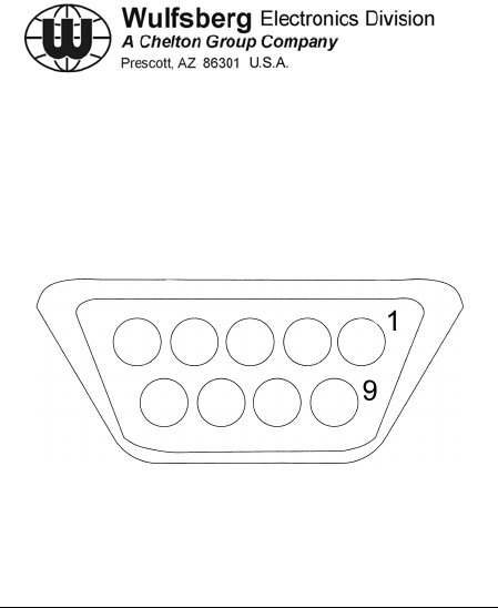
C-5000 COMMUNICATION MANAGEMENT CONTROLLER
INSTALLATION MANUAL
Page 4-22 Publication No. 150-041118
Section 4 – Electrical Installation Rev C
May 2006
C. C-5000 RS-232 Data Load Connector P503
This connector is used to program the C-5000 from a PC using a standard serial cable. It
parallels the circular connector on the front of the C-5000.
Figure 4-5. P503 Connector
PIN SIGNAL NAME
1 DIGITAL SHIELD / GROUND
2 RS-422 CTRL TX LO RX DMA
3 ON/OFF TX DATA
4 RS-422 CTRL TX HI DTR
5 RS-422 CTRL RX LO GND
6 SPARE DSR
7 IN SPARE #1 RTS
8 RS-422 CTRL RX HI CTS
9 SPARE RI
Table 4-3. C-5000 RS-232 Data Load Connector P503

C-5000 COMMUNICATION MANAGEMENT CONTROLLER
INSTALLATION MANUAL
Publication No. 150-041118 Page 4-23
Rev C Section 4 –Electrical Installation
May 2006
D. RT-5000 Transceiver Installation Wiring Considerations
(Digital Capable P/N’s 400-015525-0611 and above )
(1) J101 Connector
Figure 4-6 Connector J101

C-5000 COMMUNICATION MANAGEMENT CONTROLLER
INSTALLATION MANUAL
Page 4-24 Publication No. 150-041118
Section 4 – Electrical Installation Rev C
May 2006
(2) RT-5000 Transceiver (P/N’s 400-015525-0611 and above )
Connector J101 Pin Names.
PIN SIGNAL NAME PIN SIGNAL NAME
A AUX AUDIO IN i GUARD AUDIO INHIBIT
B AUX SIDETONE j AUDIO HI OUT
C KEY k AUDIO LO OUT
D CONTROL GND m AUDIO GND
E RS-422 ANT TX H n EXTRA WB MAIN RX AUDIO
F RS-422 ANT TX L p MAIN SQUELCH DISABLE
G RS-422 ANT RX L q WIDE BAND MN RX AUDIO OUT
H RS-422 ANT RX H r DF ENABLE
J RS-422 CTRL TX HI s DF AUDIO
K RS-422 CTRL TX LO t RS-232-RTS
L RS-422 CTRL RX LO u HOMING SIGNAL STRENGTH
M RS-422 CTRL RX HI v MN RX 180 ENABLE
N DATA SHIELD GND w WIDE BAND GD RX AUDIO OUT
P MAIN SQUELCH ANNUN x GD RX 180 ENABLE
R GUARD SQUELCH ANNUN y GUARD RX AUDIO
S RS232-RXD z TX 180 ENABLE
T RS232-TXD AA 28 VDC PWR
U RS232-CTS BB 28 VDC PWR
V ATTENUATOR CONTROL CC 28 VDC PWR
W ON/OFF DD 28 VDC PWR
X GUARD SQUELCH DISABLE EE PWR GND
Y MIC HI IN FF PWR GND
Z MIC LO/PTT IN GG PWR GND
a EXTERNAL PTT HH PWR GND
b PTT OUTPUT
c SWITCHED +15V
d TX SWITCHED +15V
e SWITCHED +27.5V
f MAIN AUDIO INHIBIT
g EXTRA WIDE BAND AUDIO IN
h WIDE BAND AUDIO IN
Table 4-4. RT-5000 Transceiver (P/N’s 400-015525-0611 and above)
Connector J101 Pin Names

C-5000 COMMUNICATION MANAGEMENT CONTROLLER
INSTALLATION MANUAL
Publication No. 150-041118 Page 4-25
Rev C Section 4 –Electrical Installation
May 2006
Pin - Signal Name
A - AUX AUDIO IN
This input will take audio from an external source unit and add to the normal
transceiver audio. Not used in normal installations.
B - AUX SIDETONE
This input will take alert tone audio from an external source and produce headset
sidetone. Not used in normal installations.
C - KEY
Bi-directional pin between the key loader and RT-5000.
D - CONTROL GND
This ground goes to the control head. Loss of this ground may disable the RT-
5000 or cause intermittent function.
E – RS-422 ANT TX H
This output is the active high sense serial data output and meets EIA RS-485
voltage levels. The data from this output controls the RT-5000 antenna.
F – RS-422 ANT TX L
This output is the active low sense serial data output and meets EIA RS-485
voltage levels. The data from this output controls the RT-5000 antenna.
G – RS-422 ANT RX L
This input is the active low sense serial data output and meets EIA RS-485
voltage levels. The data from this input comes from the RT-5000 antenna.
H – RS-422 ANT RX H
This input is the active high sense serial data output and meets EIA RS-485
voltage levels. The data from this input comes from the RT-5000 antenna.
J – RS-422 CTRL TX HI
This output is the active high sense serial data output, meets EIA RS-485 voltage
levels.
K – RS-422 CTRL TX LO
This output is the active low sense serial data output, meets EIA RS-485 voltage
levels.

C-5000 COMMUNICATION MANAGEMENT CONTROLLER
INSTALLATION MANUAL
Page 4-26 Publication No. 150-041118
Section 4 – Electrical Installation Rev C
May 2006
Pin - Signal Name
L – RS-422 CTRL RX LO
This input is the active low sense serial data input and meets EIA RS-485 voltage
levels. The data from this input comes from the C-5000.
M – RS-422 CTRL RX HI
This input is the active high sense serial data input and meets EIA RS-485
voltage levels. The data from this input comes from the C-5000.
N - DATA SHIELD GND
Spare ground.
P - MAIN SQUELCH ANNUN
This output sinks 30 mA to ground when the main receiver signal-to-noise
squelch conditions are met.
R - GUARD SQUELCH ANNUN
This output sinks 30 mA to ground when the guard receiver signal-to-noise
squelch conditions are met.
S - RS232-RXD
This pin is used to transfer information to the MTM guard.
T - RS232-TXD
This pin is used to transfer information to the MTM guard.
U - RS232-CTS
This pin is used to transfer information to the MTM guard.
V - ATTENUATOR CONTROL
When this input is pulled to ground, the RT-5000 will engage a 10 dB receive
attenuator in both main and crystal synthesized guard receivers.
W - ON/OFF
When this input is pulled to ground by the C-5000, power is applied to the RT-
5000.
X - GUARD SQUELCH DISABLE
When this input is pulled to ground, the guard squelch conditions are overridden.

C-5000 COMMUNICATION MANAGEMENT CONTROLLER
INSTALLATION MANUAL
Publication No. 150-041118 Page 4-27
Rev C Section 4 –Electrical Installation
May 2006
Pin - Signal Name
Y - MIC HI IN
This input is the standard 150 Ohm carbon microphone high input. The nominal
input is .25 Vrms and is adjustable over a range of .125 Vrms to 1.5 Vrms. The 3
dB bandwidth is 100 Hz to 8.7 kHz for raw audio and 300 Hz to 3 kHz for
processed audio per EIA specifications.
Z - MIC LO/PTT IN
This input when pulled to ground, places the radio in transmit mode if the
transmit bit is set in the serial data stream. This input also forms the low side of
the standard 150 Ohm carbon microphone.
a - EXTERNAL PTT
If the radio is controlled by a controller other than a C-5000, the RT-5000 will
transmit if this pin is grounded.
b - PTT OUTPUT
This output sinks 30ma to ground when the RT-5000 is transmitting.
c - SWITCHED +15 V
This output is capable of supplying +15 V ± 1.5 V at 500 mA.
d - TX SWITCHED +15V
When the RT-5000 is placed in transmit mode, this output supplies +15V ± 2.5V
at a maximum of 100 mA.
e - SWITCHED +27.5V
This output is capable of supplying unregulated +27.5V at 500 mA.
f - MAIN AUDIO INHIBIT
When this input is pulled to ground, the main receiver audio is disabled.
g - EXTRA WIDE BAND AUDIO IN
This input is the single ended extra wide band audio input. It has a nominal
impedance between 2k Ohms and 5k Ohms and a 3 dB bandwidth of I Hz to 40
kHz. The input is adjustable from 0.1 Vrms to 1.5 Vrms and set to .6 Vrms.

C-5000 COMMUNICATION MANAGEMENT CONTROLLER
INSTALLATION MANUAL
Page 4-28 Publication No. 150-041118
Section 4 – Electrical Installation Rev C
May 2006
Pin - Signal Name
h - WIDE BAND AUDIO IN
This input is the single ended wide band audio input. It has a nominal impedance
between 2k Ohms and 5k Ohms and a 3 dB bandwidth of 1 Hz to 27.5 kHz. The
input is adjustable from .1 Vrms to 1.5 Vrms and set to .6 Vrms.
i - GUARD AUDIO INHIBIT
When this input is pulled to ground, the guard receiver audio is disabled.
j - AUDIO HI OUT
This is the high side differential audio output. It can drive a 150 Ohm load to 100
mW and a 600 Ohm load to 25 mW. 3 dB bandwidth is 300 Hz to 3 kHz.
k - AUDIO LO OUT
This is the low side differential audio output. It can drive a 150 Ohm load to 100
mW and a 600 Ohm load to 25 mW. 3 dB bandwidth is 300 Hz to 3 kHz.
m - AUDIO GND
This ground is for shielding the audio outputs.
n - EXTRA WB MAIN RX AUDIO
This output is the single ended extra wide band audio output. It is capable of
driving a 2k Ohm impedance and has a 3 dB bandwidth of 1 Hz to 40 kHz. The
output is adjustable from .1 Vrms to 1.5 Vrms and set to .6 Vrms.
p - MAIN SQUELCH DISABLE
When this input is pulled to ground, the main squelch conditions are overridden.
q - WIDE BAND MN RX AUDIO OUT
This output is the single ended audio output. It is capable of driving a 2k Ohm
impedance and has a bandwidth of 1 Hz to 27.5 kHz.
r - DF ENABLE
Grounding this input enables the DF audio output. DF function only available
when using the main receiver. Digital channels do not have DF capability.
s - DF AUDIO
This output produces an output proportional to the AM signal. The output has a 3
dB bandwidth of 1Hz to 10 kHz. The output will drive a 2k Ohm impedance. The
output is adjustable from. 1 Vrms to 1.5 Vrms and set to .1.4 Vrms (4Vp-p).

C-5000 COMMUNICATION MANAGEMENT CONTROLLER
INSTALLATION MANUAL
Publication No. 150-041118 Page 4-29
Rev C Section 4 –Electrical Installation
May 2006
Pin - Signal Name
t – RS-232-RTS
This pin is used to transfer information to the MTM guard.
u - HOMING SIGNAL STRENGTH
This output produces an output based on the signal strength that varies between
0 and 8 VDC, and is capable of driving a 2k Ohm load. This signal has a 3 dB
bandwidth between DC and 50 Hz.
v - MN RX 180 ENABLE
Grounding this input causes 180 degrees of phase shift in the main received
audio.
w - WIDE BAND GUARD RX AUDIO OUT
This output is the single ended wide band guard audio output. It is capable of
driving a 2k Ohm impedance and has a 3 dB bandwidth of 1 Hz to 27.5 kHz. The
output is adjustable from .1 Vrms to 1.5 Vrms and set to .6 Vrms.
x - GD RX 180 ENABLE
Grounding this input causes 180 degrees of phase shift in the guard received
audio.
y - GUARD RX AUDIO
This output is the single ended guard audio output. It is capable of driving a 2k
Ohm impedance and has a 3 dB bandwidth of 1 Hz to 3kHz. The output is
adjustable from .1 Vrms to 1.5 Vrms and set to .6 Vrms.
z - TX 180 ENABLE
Grounding this input causes 180 degrees of phase shift in the transmitted audio.
This phase shift may be required when using an external encryption device.
AA, BB, CC, DD – 28 VDC PWR
Input Aircraft power pins.
EE, FF, GG, HH – PWR GND
Input Aircraft power ground pins.
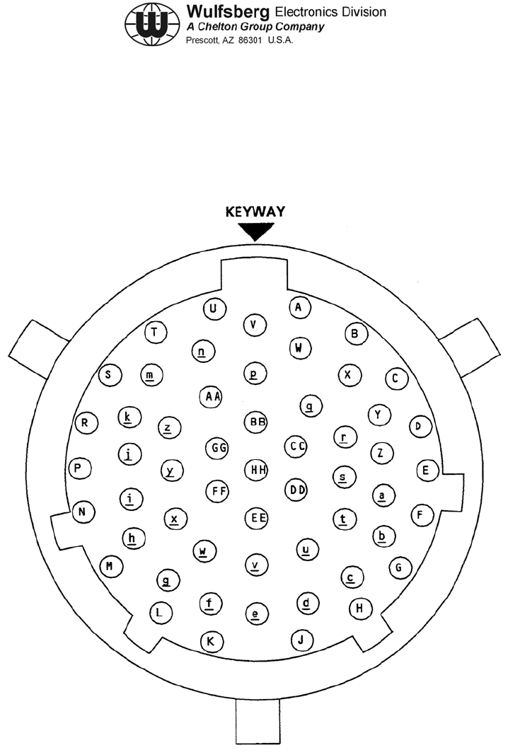
C-5000 COMMUNICATION MANAGEMENT CONTROLLER
INSTALLATION MANUAL
Page 4-30 Publication No. 150-041118
Section 4 – Electrical Installation Rev C
May 2006
E. RT-5000 Transceiver Installation Wiring Considerations
(P/N’s 400-015525-0101 to 0501)
(1) J101 Connector
Figure 4-7 Connector J101

C-5000 COMMUNICATION MANAGEMENT CONTROLLER
INSTALLATION MANUAL
Publication No. 150-041118 Page 4-31
Rev C Section 4 –Electrical Installation
May 2006
(2) RT-5000 Transceiver (P/N’s 400-015525-0101 to 0501)
Connector J101 Pin Names.
PIN SIGNAL NAME PIN SIGNAL NAME
A AUX AUDIO IN i GUARD AUDIO INHIBIT
B AUX SIDETONE j AUDIO HI OUT
C RES SPARE A k AUDIO LO OUT
D CONTROL GND m AUDIO GND
E RS-422 ANT TX H n EXTRA WB MAIN RX AUDIO
F RS-422 ANT TX L p MAIN SQUELCH DISABLE
G RS-422 ANT RX L q WIDE BAND MN RX AUDIO OUT
H RS-422 ANT RX H r DF ENABLE
J RS-422 CTRL TX HI s DF AUDIO
K RS-422 CTRL TX LO t RES SPARE B
L RS-422 CTRL RX LO u HOMING SIGNAL STRENGTH
M RS-422 CTRL RX HI v MN RX 180 ENABLE
N DATA SHIELD GND w WIDE BAND GD RX AUDIO OUT
P MAIN SQUELCH ANNUN x GD RX 180 ENABLE
R GUARD SQUELCH ANNUN y GUARD RX AUDIO
S AM/FM MODE INDICATOR z TX 180 ENABLE
T VHF/UHF MODE INDICATOR AA 28 VDC PWR
U VHF_LO MODE INDICATOR BB 28 VDC PWR
V ATTENUATOR CONTROL CC 28 VDC PWR
W ON/OFF DD 28 VDC PWR
X GUARD SQUELCH DISABLE EE PWR GND
Y MIC HI IN FF PWR GND
Z MIC LO/PTT IN GG PWR GND
a EXTERNAL PTT HH PWR GND
b PTT OUTPUT
c SWITCHED +15V
d TX SWITCHED +15V
e SWITCHED +27.5V
f MAIN AUDIO INHIBIT
g EXTRA WIDE BAND AUDIO IN
h WIDE BAND AUDIO IN
Table 4-5. RT-5000 Transceiver (P/N’s 400-015525-0101 to 0501)
Connector J101 Pin Names

C-5000 COMMUNICATION MANAGEMENT CONTROLLER
INSTALLATION MANUAL
Page 4-32 Publication No. 150-041118
Section 4 – Electrical Installation Rev C
May 2006
Pin - Signal Name
A - AUX AUDIO IN
This input will take audio from an external source unit and add to the normal
transceiver audio. Not used in normal installations.
B - AUX SIDETONE
This input will take alert tone audio from an external source and produce headset
sidetone. Not used in normal installations.
C – RESERVED SPARE A
D - CONTROL GND
This ground goes to the control head. Loss of this ground may disable the RT-
5000 or cause intermittent function.
E – RS-422 ANT TX H
This output is the active high sense serial data output and meets EIA RS-485
voltage levels. The data from this output controls the RT-5000 antenna.
F – RS-422 ANT TX L
This output is the active low sense serial data output and meets EIA RS-485
voltage levels. The data from this output controls the RT-5000 antenna.
G – RS-422 ANT RX L
This input is the active low sense serial data output and meets EIA RS-485
voltage levels. The data from this input comes from the RT-5000 antenna.
H – RS-422 ANT RX H
This input is the active high sense serial data output and meets EIA RS-485
voltage levels. The data from this input comes from the RT-5000 antenna.
J – RS-422 CTRL TX HI
This output is the active high sense serial data output, meets EIA RS-485 voltage
levels.
K – RS-422 CTRL TX LO
This output is the active low sense serial data output, meets EIA RS-485 voltage
levels.

C-5000 COMMUNICATION MANAGEMENT CONTROLLER
INSTALLATION MANUAL
Publication No. 150-041118 Page 4-33
Rev C Section 4 –Electrical Installation
May 2006
Pin - Signal Name
L – RS-422 CTRL RX LO
This input is the active low sense serial data input and meets EIA RS-485 voltage
levels. The data from this input comes from the C-5000.
M – RS-422 CTRL RX HI
This input is the active high sense serial data input and meets EIA RS-485
voltage levels. The data from this input comes from the C-5000.
N - DATA SHIELD GND
Spare ground.
P - MAIN SQUELCH ANNUN
This output sinks 30 mA to ground when the main receiver signal-to-noise
squelch conditions are met.
R - GUARD SQUELCH ANNUN
This output sinks 30 mA to ground when the guard receiver signal-to-noise
squelch conditions are met.
S – AM/FM MODE INDICATOR
This output sinks 30mA to ground when the RT-5000 is in AM mode.
T – VHF/UHF MODE INDICATOR
This output sinks 30mA to ground when the RT-5000 is tuned to a frequency that
is less than 400 MHz.
U – VHF_LO MODE INDICATOR
This output sinks 30mA to ground when the active frequency is less than 88
MHz.
V - ATTENUATOR CONTROL
When this input is pulled to ground, the RT-5000 will engage a 10 dB receive
attenuator in both main and crystal synthesized guard receivers.
W - ON/OFF
When this input is pulled to ground by the C-5000, power is applied to the RT-
5000.

C-5000 COMMUNICATION MANAGEMENT CONTROLLER
INSTALLATION MANUAL
Page 4-34 Publication No. 150-041118
Section 4 – Electrical Installation Rev C
May 2006
Pin - Signal Name
X - GUARD SQUELCH DISABLE
When this input is pulled to ground, the guard squelch conditions are overridden.
Y - MIC HI IN
This input is the standard 150 Ohm carbon microphone high input. The nominal
input is .25 Vrms and is adjustable over a range of .125 Vrms to 1.5 Vrms. The 3
dB bandwidth is 100 Hz to 8.7 kHz for raw audio and 300 Hz to 3 kHz for
processed audio per EIA specifications.
Z - MIC LO/PTT IN
This input when pulled to ground, places the radio in transmit mode if the
transmit bit is set in the serial data stream. This input also forms the low side of
the standard 150 Ohm carbon microphone.
a - EXTERNAL PTT
If the radio is controlled by a controller other than a C-5000, the RT-5000 will
transmit if this pin is grounded.
b - PTT OUTPUT
This output sinks 30ma to ground when the RT-5000 is transmitting.
c - SWITCHED +15 V
This output is capable of supplying +15 V ± 1.5 V at 500 mA.
d - TX SWITCHED +15V
When the RT-5000 is placed in transmit mode, this output supplies +15V ± 2.5V
at a maximum of 100 mA.
e - SWITCHED +27.5V
This output is capable of supplying unregulated +27.5V at 500 mA.
f - MAIN AUDIO INHIBIT
When this input is pulled to ground, the main receiver audio is disabled.
g - EXTRA WIDE BAND AUDIO IN
This input is the single ended extra wide band audio input. It has a nominal
impedance between 2k Ohms and 5k Ohms and a 3 dB bandwidth of I Hz to 40
kHz. The input is adjustable from 0.1 Vrms to 1.5 Vrms and set to .6 Vrms.

C-5000 COMMUNICATION MANAGEMENT CONTROLLER
INSTALLATION MANUAL
Publication No. 150-041118 Page 4-35
Rev C Section 4 –Electrical Installation
May 2006
Pin - Signal Name
h - WIDE BAND AUDIO IN
This input is the single ended wide band audio input. It has a nominal impedance
between 2k Ohms and 5k Ohms and a 3 dB bandwidth of 1 Hz to 27.5 kHz. The
input is adjustable from .1 Vrms to 1.5 Vrms and set to .6 Vrms.
i - GUARD AUDIO INHIBIT
When this input is pulled to ground, the guard receiver audio is disabled.
j - AUDIO HI OUT
This is the high side differential audio output. It can drive a 150 Ohm load to 100
mW and a 600 Ohm load to 25 mW. 3 dB bandwidth is 300 Hz to 3 kHz.
k - AUDIO LO OUT
This is the low side differential audio output. It can drive a 150 Ohm load to 100
mW and a 600 Ohm load to 25 mW. 3 dB bandwidth is 300 Hz to 3 kHz.
m - AUDIO GND
This ground is for shielding the audio outputs.
n - EXTRA WB MAIN RX AUDIO
This output is the single ended extra wide band audio output. It is capable of
driving a 2k Ohm impedance and has a 3 dB bandwidth of 1 Hz to 40 kHz. The
output is adjustable from .1 Vrms to 1.5 Vrms and set to .6 Vrms.
p - MAIN SQUELCH DISABLE
When this input is pulled to ground, the main squelch conditions are overridden.
q - WIDE BAND MN RX AUDIO OUT
This output is the single ended audio output. It is capable of driving a 2k Ohm
impedance and has a bandwidth of 1 Hz to 27.5 kHz.
r - DF ENABLE
Grounding this input enables the DF audio output. DF function only available
when using the main receiver. Digital channels do not have DF capability.
s - DF AUDIO
This output produces an output proportional to the AM signal. The output has a 3
dB bandwidth of 1Hz to 10 kHz. The output will drive a 2k Ohm impedance. The
output is adjustable from. 1 Vrms to 1.5 Vrms and set to .1.4 Vrms (4Vp-p).

C-5000 COMMUNICATION MANAGEMENT CONTROLLER
INSTALLATION MANUAL
Page 4-36 Publication No. 150-041118
Section 4 – Electrical Installation Rev C
May 2006
Pin - Signal Name
t – RESERVED SPARE B
This pin is used to transfer information to the MTM guard.
u - HOMING SIGNAL STRENGTH
This output produces an output based on the signal strength that varies between
0 and 8 VDC, and is capable of driving a 2k Ohm load. This signal has a 3 dB
bandwidth between DC and 50 Hz.
v - MN RX 180 ENABLE
Grounding this input causes 180 degrees of phase shift in the main received
audio.
w - WIDE BAND GUARD RX AUDIO OUT
This output is the single ended wide band guard audio output. It is capable of
driving a 2k Ohm impedance and has a 3 dB bandwidth of 1 Hz to 27.5 kHz. The
output is adjustable from .1 Vrms to 1.5 Vrms and set to .6 Vrms.
x - GD RX 180 ENABLE
Grounding this input causes 180 degrees of phase shift in the guard received
audio.
y - GUARD RX AUDIO
This output is the single ended guard audio output. It is capable of driving a 2k
Ohm impedance and has a 3 dB bandwidth of 1 Hz to 3kHz. The output is
adjustable from .1 Vrms to 1.5 Vrms and set to .6 Vrms.
z - TX 180 ENABLE
Grounding this input causes 180 degrees of phase shift in the transmitted audio.
This phase shift may be required when using an external encryption device.
AA, BB, CC, DD – 28 VDC PWR
Input Aircraft power pins.
EE, FF, GG, HH – PWR GND
Input Aircraft power ground pins.
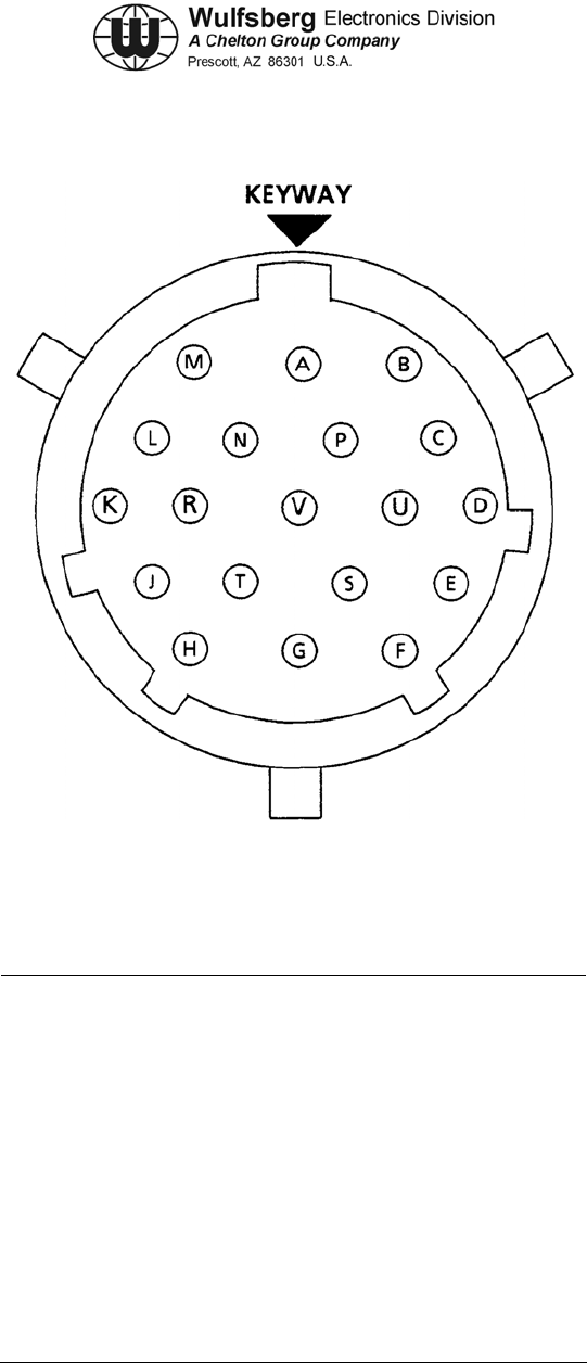
C-5000 COMMUNICATION MANAGEMENT CONTROLLER
INSTALLATION MANUAL
Publication No. 150-041118 Page 4-37
Rev C Section 4 –Electrical Installation
May 2006
PIN SIGNAL NAME PIN SIGNAL NAME
A RX DATA H L S0
B RX DATA L M GROUND
C TX DATA H N
D TX DATA L P GROUND
E GROUND R
F S S3
G T NC
H GROUND U NC
J NC V
K NC
Figure 4-8. FC-50 / FC-550 / FC-5000 Connector J1
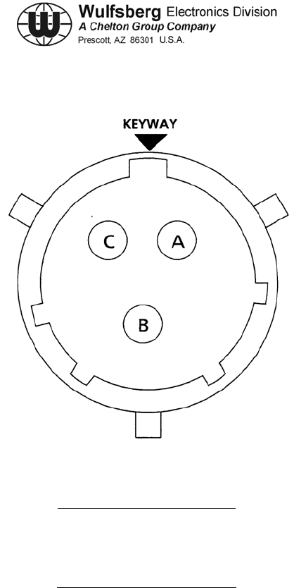
C-5000 COMMUNICATION MANAGEMENT CONTROLLER
INSTALLATION MANUAL
Page 4-38 Publication No. 150-041118
Section 4 – Electrical Installation Rev C
May 2006
PIN SIGNAL NAME
A 28 VDC
B DC RTN
C GND
Figure 4-9. FC-50 / FC-550 / FC-5000 Connector J2
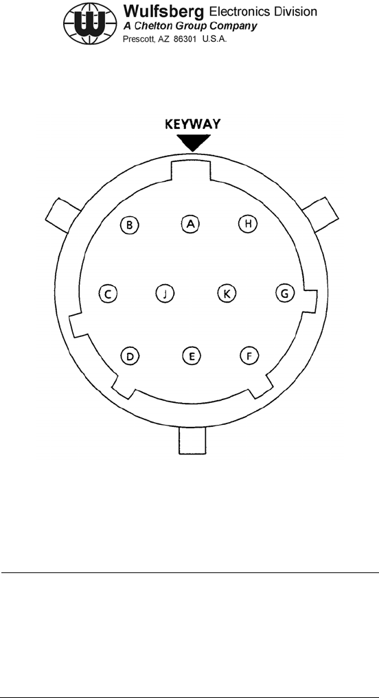
C-5000 COMMUNICATION MANAGEMENT CONTROLLER
INSTALLATION MANUAL
Publication No. 150-041118 Page 4-39
Rev C Section 4 –Electrical Installation
May 2006
NOTE: FC-50 Connector J3 connects to AT-50/AT-51 antennas. These pins provide proprietary
channeling information to the antenna.
PIN SIGNAL NAME PIN SIGNAL NAME
A Proprietary F Proprietary
B Proprietary G Proprietary
C Proprietary H Proprietary
D Proprietary J Proprietary
E Proprietary K Proprietary
Figure 4-10. FC-50 / FC-550 / FC-5000 Connector J3

C-5000 COMMUNICATION MANAGEMENT CONTROLLER
INSTALLATION MANUAL
Page 4-40 Publication No. 150-041118
Section 4 – Electrical Installation Rev C
May 2006
This page intentionally left blank.

C-5000 COMMUNICATION MANAGEMENT CONTROLLER
INSTALLATION MANUAL
Publication No. 150-041118 Page 4-41
Rev C Section 4 –Electrical Installation
May 2006
Remove this page and insert 152-140131 Sheet 1 of 17 (Figure 4-11a)

C-5000 COMMUNICATION MANAGEMENT CONTROLLER
INSTALLATION MANUAL
Page 4-42 Publication No. 150-041118
Section 4 – Electrical Installation Rev C
May 2006
Remove this page.

C-5000 COMMUNICATION MANAGEMENT CONTROLLER
INSTALLATION MANUAL
Publication No. 150-041118 Page 4-43
Rev C Section 4 –Electrical Installation
May 2006
Remove this page and insert 152-140131 Sheet 2 of 17 (Figure 4-11b)

C-5000 COMMUNICATION MANAGEMENT CONTROLLER
INSTALLATION MANUAL
Page 4-44 Publication No. 150-041118
Section 4 – Electrical Installation Rev C
May 2006
Remove this page.

C-5000 COMMUNICATION MANAGEMENT CONTROLLER
INSTALLATION MANUAL
Publication No. 150-041118 Page 4-45
Rev C Section 4 –Electrical Installation
May 2006
Remove this page and insert 152-140131 Sheet 3 of 17 (Figure 4-11c)

C-5000 COMMUNICATION MANAGEMENT CONTROLLER
INSTALLATION MANUAL
Page 4-46 Publication No. 150-041118
Section 4 – Electrical Installation Rev C
May 2006
Remove this page.

C-5000 COMMUNICATION MANAGEMENT CONTROLLER
INSTALLATION MANUAL
Publication No. 150-041118 Page 4-47
Rev C Section 4 –Electrical Installation
May 2006
Remove this page and insert 152-140131 Sheet 4 of 17 (Figure 4-11d)

C-5000 COMMUNICATION MANAGEMENT CONTROLLER
INSTALLATION MANUAL
Page 4-48 Publication No. 150-041118
Section 4 – Electrical Installation Rev C
May 2006
Remove this page.

C-5000 COMMUNICATION MANAGEMENT CONTROLLER
INSTALLATION MANUAL
Publication No. 150-041118 Page 4-49
Rev C Section 4 –Electrical Installation
May 2006
Remove this page and insert 152-140131 Sheet 5 of 17 (Figure 4-11e)

C-5000 COMMUNICATION MANAGEMENT CONTROLLER
INSTALLATION MANUAL
Page 4-50 Publication No. 150-041118
Section 4 – Electrical Installation Rev C
May 2006
Remove this page.

C-5000 COMMUNICATION MANAGEMENT CONTROLLER
INSTALLATION MANUAL
Publication No. 150-041118 Page 4-51
Rev C Section 4 –Electrical Installation
May 2006
Remove this page and insert 152-140131 Sheet 6 of 17 (Figure 4-11f)

C-5000 COMMUNICATION MANAGEMENT CONTROLLER
INSTALLATION MANUAL
Page 4-52 Publication No. 150-041118
Section 4 – Electrical Installation Rev C
May 2006
Remove this page.

C-5000 COMMUNICATION MANAGEMENT CONTROLLER
INSTALLATION MANUAL
Publication No. 150-041118 Page 4-53
Rev C Section 4 –Electrical Installation
May 2006
Remove this page and insert 152-140131 Sheet 7 of 17 (Figure 4-11g)