XTC Motorsports XTC5000 Digital Satellite Receiver User Manual Microsoft PowerPoint XTC5000
XTC Motorsports Inc. Digital Satellite Receiver Microsoft PowerPoint XTC5000
Contents
- 1. Users Manual Part I
- 2. Users Manual Part II
- 3. Users Manual Part III
Users Manual Part III

34
In Main Page, press ●Edit key on the RCU,
and then select Rename CH on the command
menu.
This Rename CH command allow you to rename
the channel. First select the channel, which you
want to lock, pressing OK key and then Keypad
Dialog Box will be displayed. Edit your desired
name entering word or number.
(If you select ◀, it deletes the previous word)
And check whether the channel name is changed
on channel list.
Lock Channel
Rename Channel
CHANNEL MANAGER
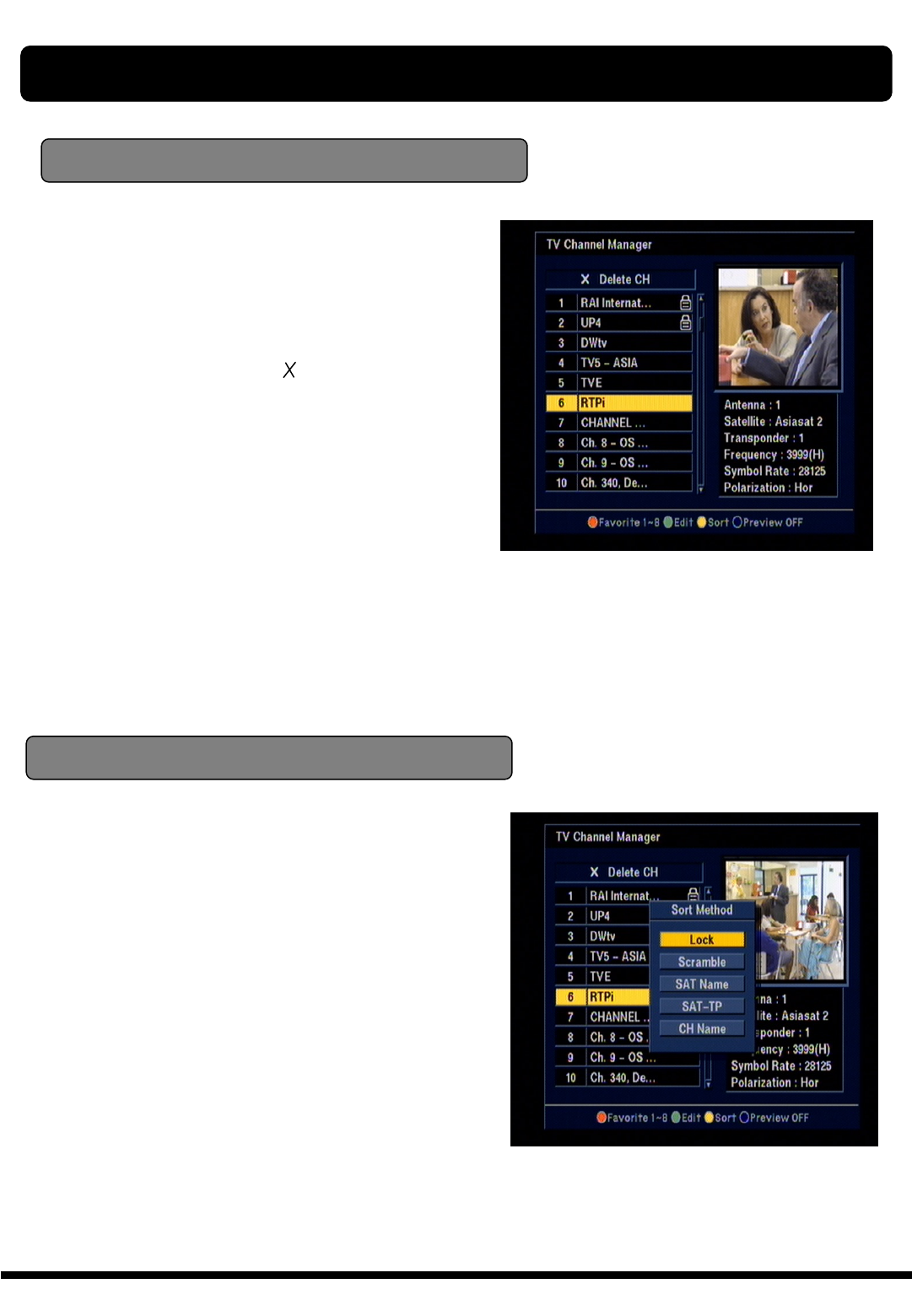
In Main Page, press ●SORT key on the RCU,
and then select Lock on the command menu.
This Lock command allow you to lock the channel.
First select the channel, which you want to lock,
pressing OK key and then will be marked at
rear of your selected channel name.
Note : To perform this function, you should set up
the Parent Lock which is explained after.
35
In Main Page, press ●SORT key on the RCU,
and Sort Method will be displayed.
This Sort method has 4 sub commands and it
allows you to sort the channels as provided.
You can sort the channels by Lock, Scramble,
SAT name and CH name.
Place the cursor on your desired line, and then
press OK key.
And check whether the channels are sorted
exiting on the channel list.
Delete channel
In Main Page, press ●Edit key on the RCU, and
then select Delete on the command menu.
This Delete command allows you to delete the
channel permanently. First select the channels,
which you want to delete, then selected channel
number will be changed to If you cancel the
selection, press OK key again, then the number
will be back as it was
If you decided to delete, press EXIT key and then
Message box will be displayed. Press OK to
delete.
And check whether the channel number is
changed exiting on channel list.
Warning : The deleted channel can not be
recovered unless you search again. Please be
careful when you decide to delete channel.
Sort Method
Note : Radio Channel Manager is same operation
as TV channel Manager.
CHANNEL MANAGER
36
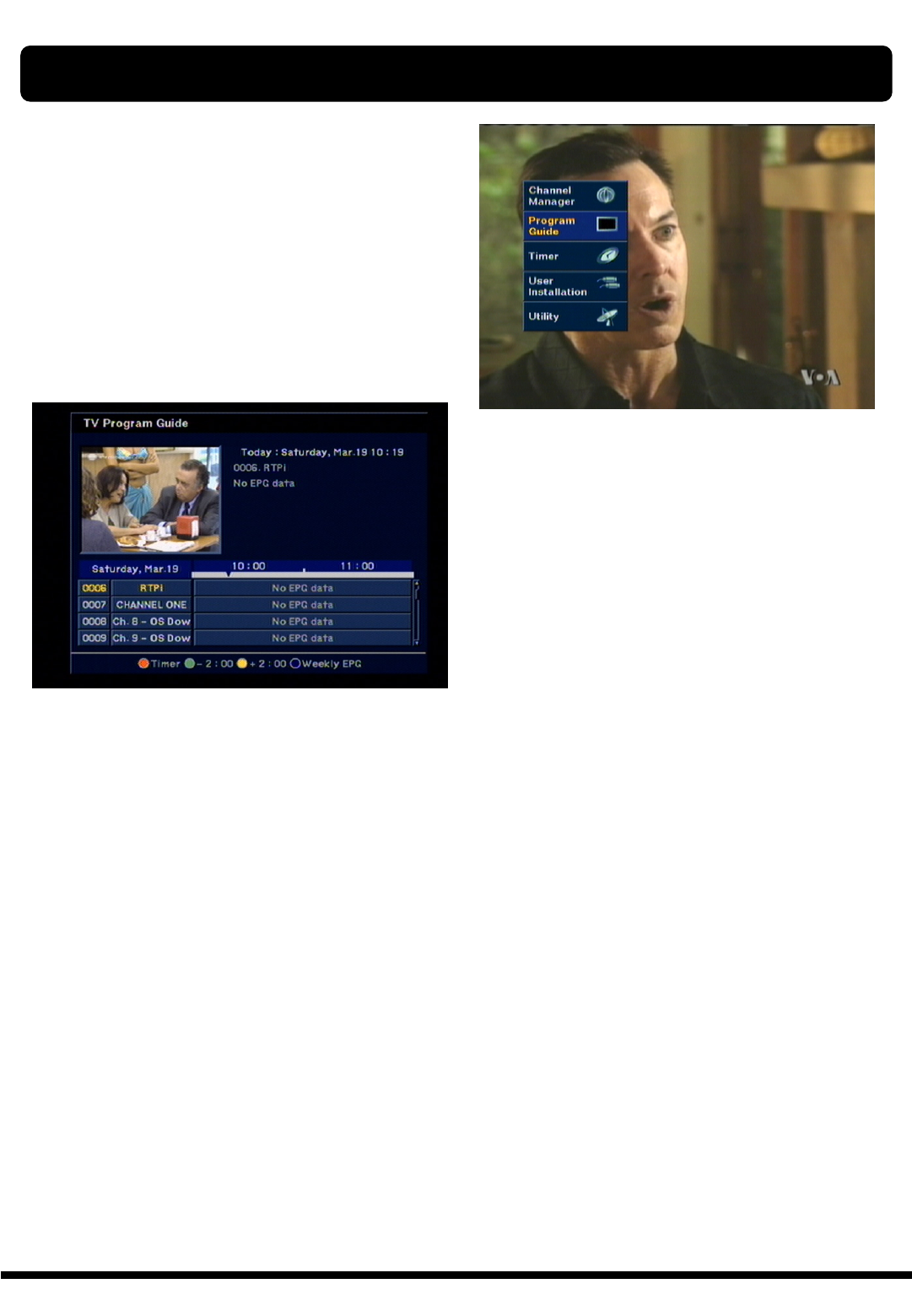
XTC 5000 provides EPG function for you to get
access to the TV Guide(or Radio Guide if you are
listening to radio channels) which will give the
titles of the current and next programs on different
channels. The information is only available from
the network to which the channel you are
watching belongs.
Press EPG key on your RCU or select Program
Guide in the Main Page.
Two different types of EPG available, which is
GRID EPG and Weekly EPG
You can see the channel list in the left side and
Program schedule for selected channel will be
displayed in the right side. The time will be
displayed relating to the program schedule.
Select one channel and placing the “▼”mark on
the time of Program name which detail information
you want to know. Then you can see the program
changes blue color. And press OK key, then detail
information box will be displayed.
Note : A ‘No data available” message will be
shown if the selected channel does not provide
EPG date.
ELECTRONIC PROGRAM GUIDE (EPG)
37
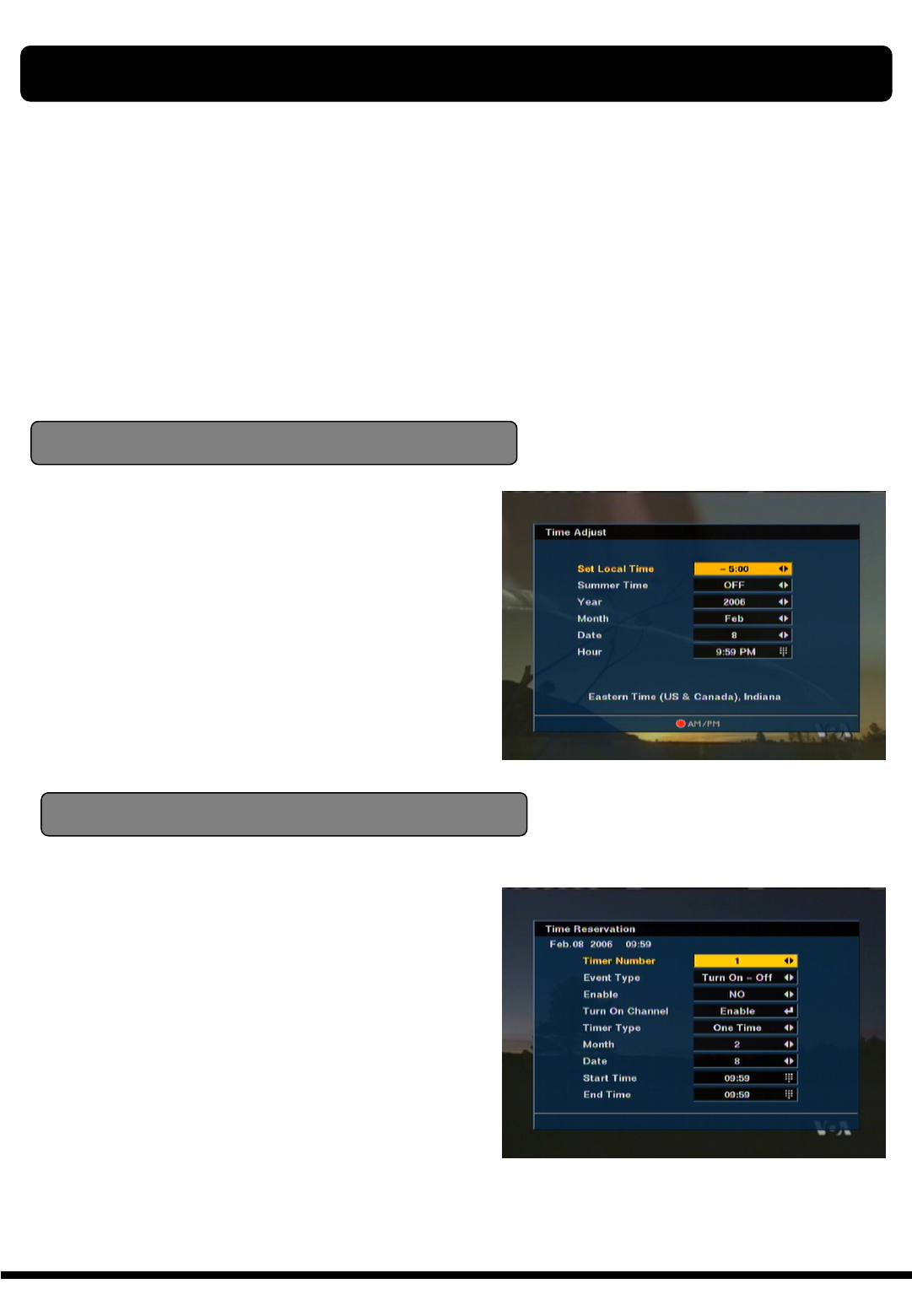
The “TIMER” function allows you program the timer
with various ways. This function is one of the
strong point of XTC 5000
To activate the “Turn on time” and/or “Turn Off the
time”, Select YES and enter your desired time.
Note : The XTC 5000 display the time which is
given by Satellite, so it may be a some differences
between actual time and XTC 5000 ’s time.
Time Adjust
To activate the “Turn on time” and/or “Turn Off
the time”, select YES and enter your desired
time.
And you can also select channel which will be
turn on or turn off.
Time Reservation
Time Reservation allows you to program the
various timer function.
You can set the timer daily, weekly, monthly and
yearly
Note : Easy timer is default for the first time.
TIMER
38
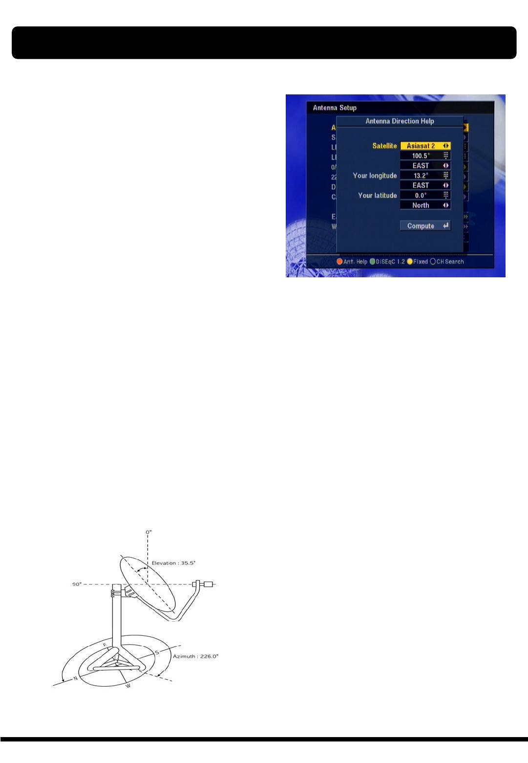
Although you entered correct value in Antenna
Set up menu, if your antenna is positioned
incorrectly, you could not receive signal form the
Satellite.
So XTC 5000 provides Antenna Direction Help in
order for you to have exact information for the
pointing of your antenna.
First select your desired Satellite name and then
the location of selected satellite will be displayed.
In case of that the location of the satellite is
changed, you can re-set up the new location.
Second, enter the value of Longitude and Latitude
of your location.
If you entered correct value of your position, place
your cursor on Compute and press OK key.
Then XTC 5000 show the exact information of
antenna pointing.
ANTENNA DIRECTION HELP
39
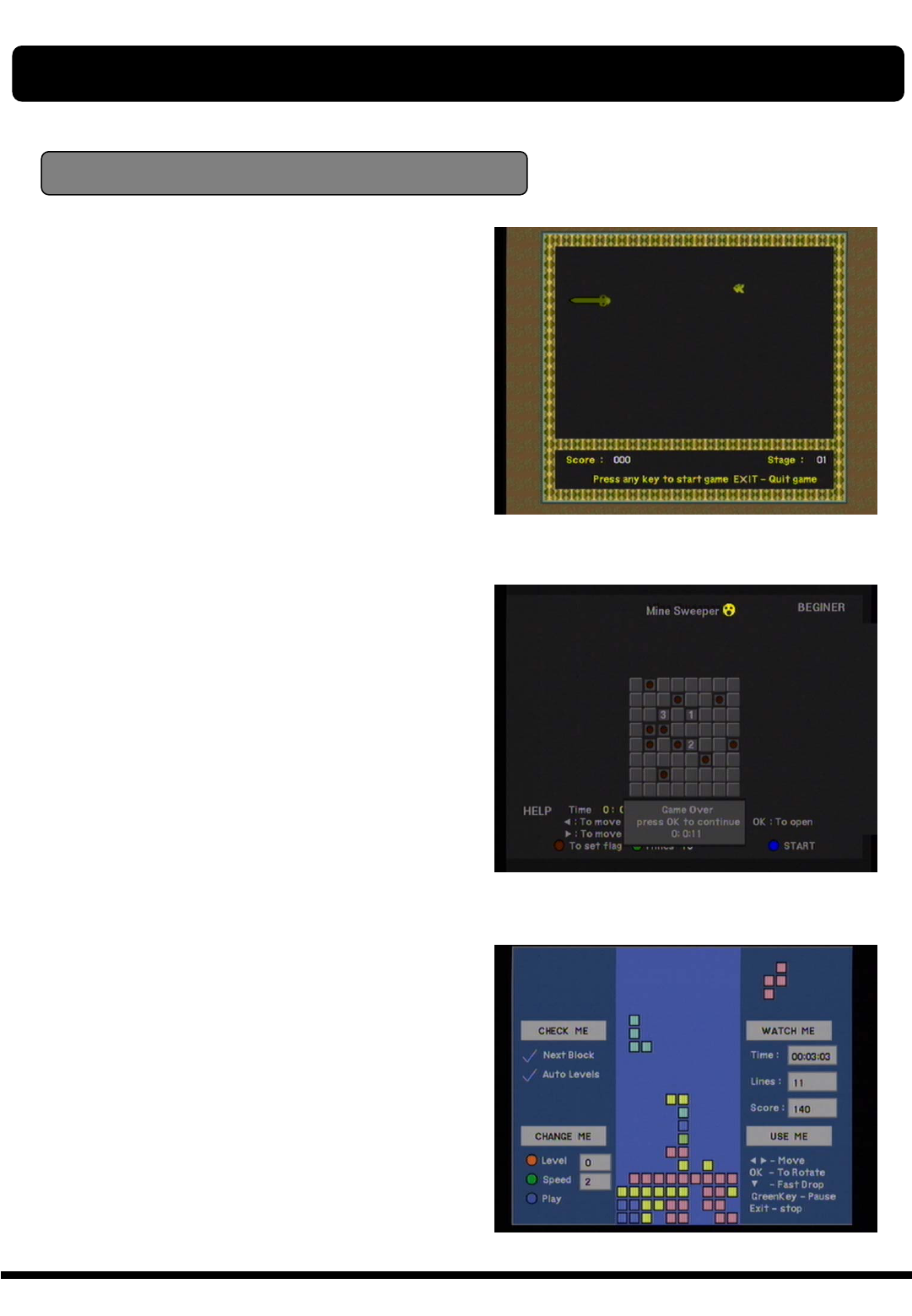
GAME
GAME
XTC 5000 provides you with three different
types of very exciting video games.
The video games are simply available at
the sub-menu of the main menu “Utility”.
The available games are,
1) SNAKE
2) MINE SWEEPER
3) CRAZY TETRIS
40
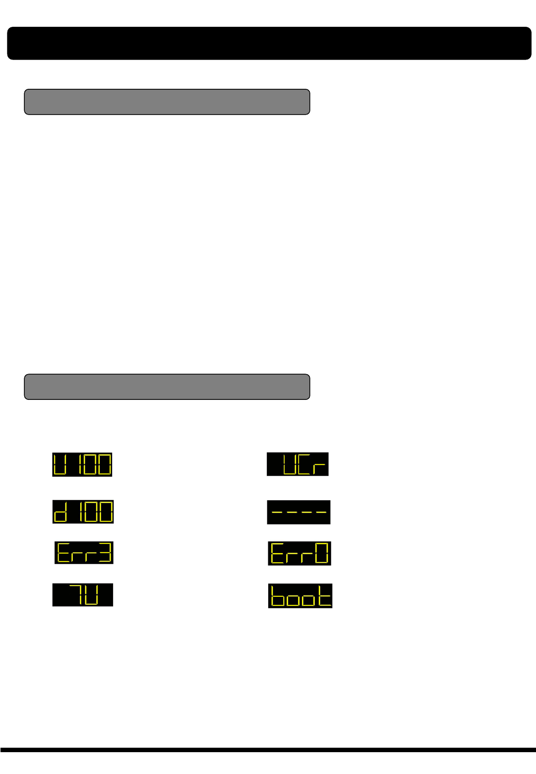
: UP LOAD PROCEDURE
: DOWN LOAD
PROCEDURE
: ERROR IN DATA
TRANSMITTING
: TV MODE
: VCR MODE
: SYSTEM WAITTING
: FLASH ROM ERROR
: SYSTEM BOOTING
In the Receiver Information, you can show the
information of the product, its version and
contact point of supplier. If you have a problem
on this products and any question, please feel
free to contact the supplier which contact point is
mentioned in this Receiver Information.
RECEIVER INFO & FRONT PANEL DISPLAY
Receiver Information
Front Panel Display
41
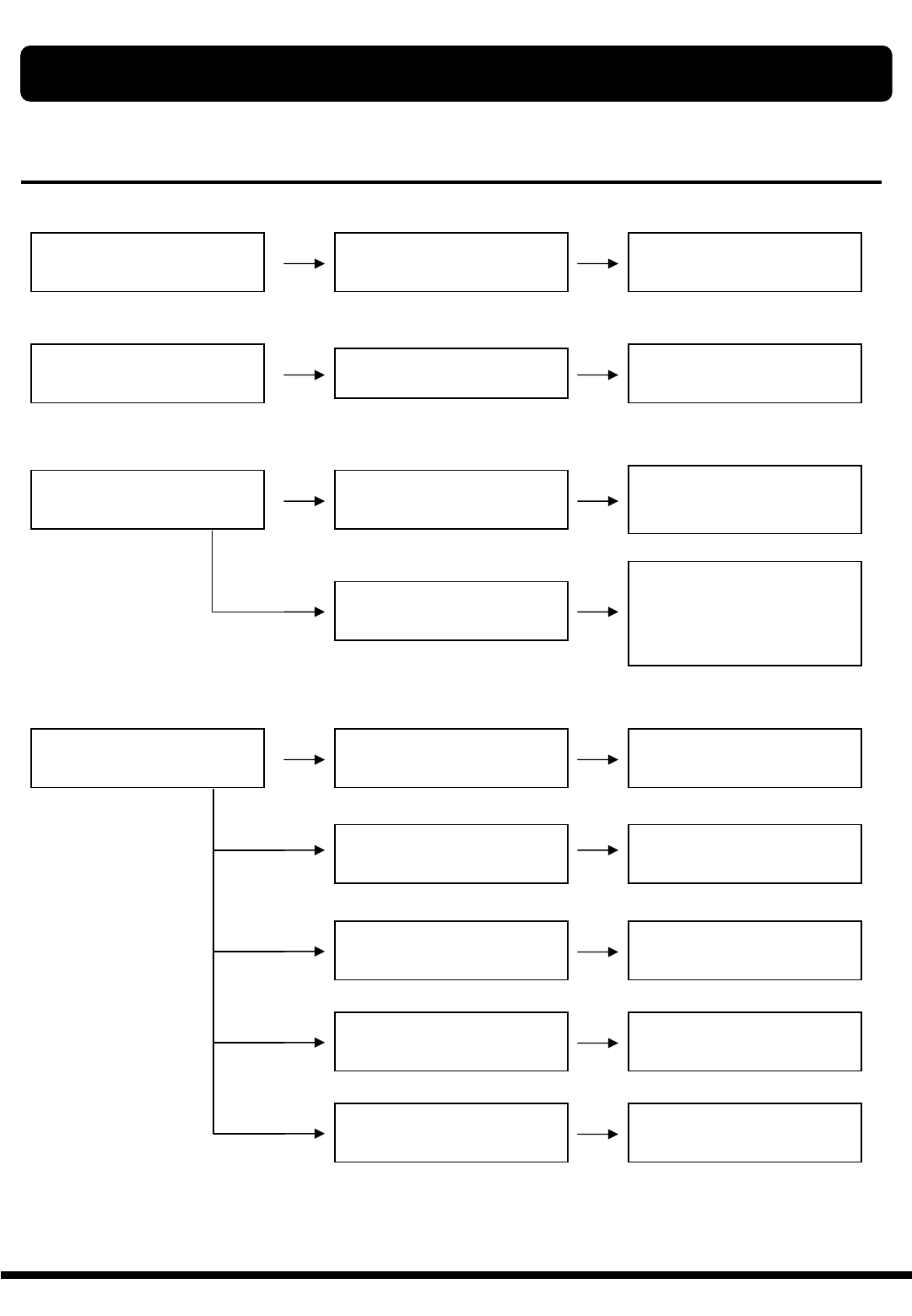
Problem Possible causes What to do
The display on the front panel
does not light up.
Main cable is not connected. Check that the main cable is
plugged into the power socket.
No sound or picture, but the
front panel shows red light. The XTC 5000 is in standby
mode. Press the standby button.
No sound or picture. The satellite dish is not
pointing at the satellite.
Adjust the dish. Check the
signal level in the Antenna
Setup menu.
No signal or weak signal. Check the cable connections,
LNB and other equipment
connected between the LNB
and the receiver, or adjust the
dish.
Bad picture / blocking error. The satellite dish is not
pointing at the satellite.
Adjust the dish.
Signal is too strong. Connect a signal attenuator to
the LNB input.
Satellite dish is too small. Change to a larger dish.
LNB noise factor too high. Change to an LNB with lower
noise factor.
The LNB is faulty. Change the LNB.
TROUBLE SHOOTING
42
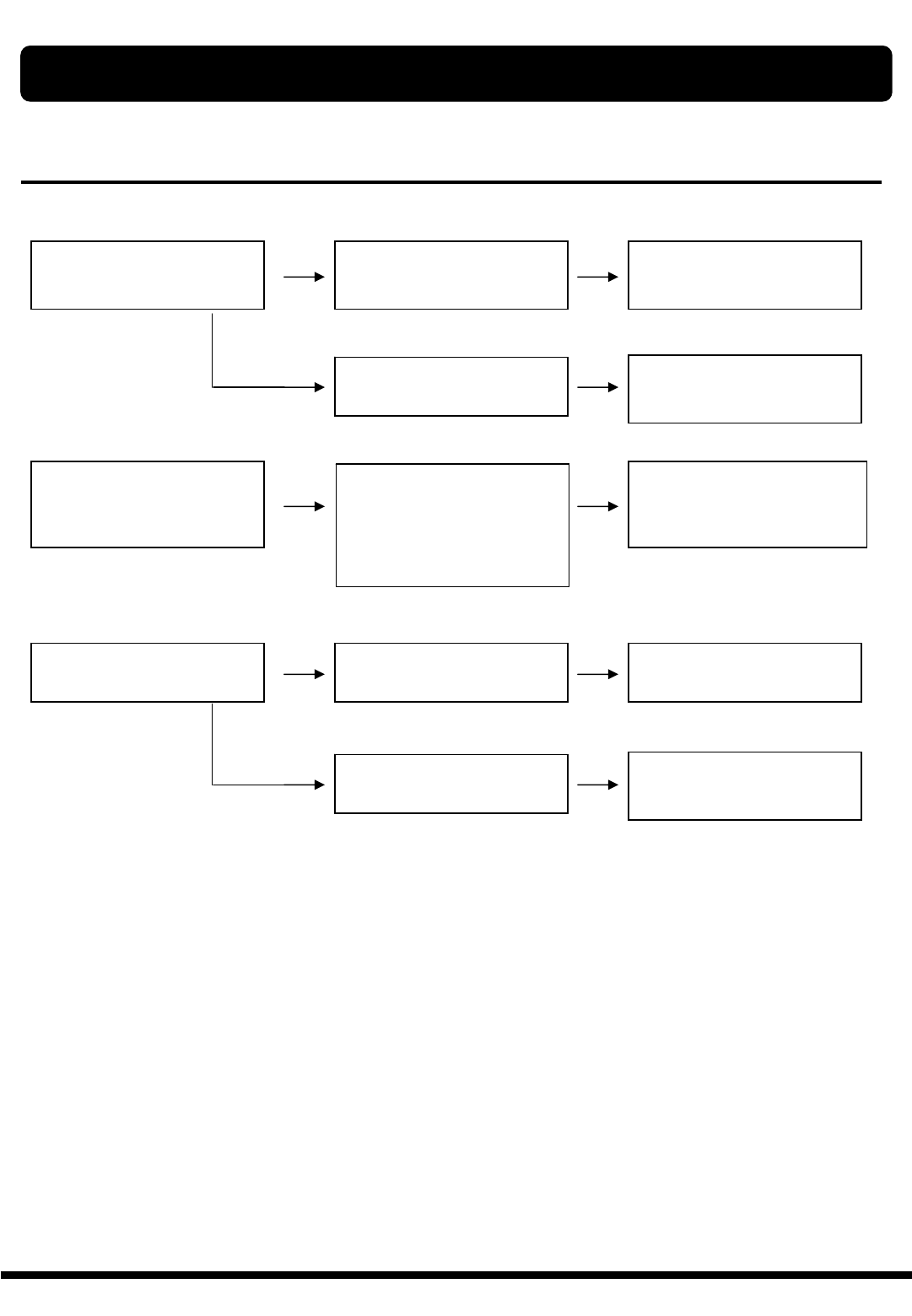
Problem Possible causes What to do
No Welcome Menu on the
screen after you switched on
the XTC 5000 for the first time.
The system is connected by
SCART leads and TV is not in
AV/EXT mode.
If the system is connected by
SCART leads, switch the TV to
the appropriate AV input.
The system is connected by
RF leads.
Check the UHF channel fixed
in your system and tune the
UHF channel properly..
There is interface on your
digital satellite channels, an
existing terrestrial channel or
video signal.
The system is connected by
RF leads and the output
channel of the XTC 5000
interferes with an existing
terrestrial channels or Video
signal.
Change the XTC 5000 output
channel to a more suitable
channel, or connect the system
by SCART leads.
The RCU is not
working.
Battery exhausted. Change the batteries.
RCU is incorrectly
aimed.
Aim RCU at XTC 5000, or
check that nothing blocks the
front panel.
Note :
If you have tried all of the actions suggested above, without solving the problem,
please contact your dealer or service provider.
TROUBLE SHOOTING

43
SYSTEM SPECIFICATION
1) SYSTEM CAPACITY
Fully MPEG2, DVB complaint
2) DEMODULATION
QPSK demodulation and FEC decoding
Symbol rate (Rs) 2 < Rs < 45 Mbaud
3) VIDEO DECODER
MPEG-2 Main Profile @ Main Level With Letter Box filter
Data rate up to 15Mbits/s
Video Formats 4:3, 16:9
4) AUDIO DECODER
MPEG-1 layer I and II, Musicam
Stereo Channel, Dual Mono, Joint Stereo Channel, Mono
5) PROCESSOR RESSOURCES
Processor SGS-Thomson Sti5518
SDRAM 8 Mbyte
Flash 2 Mbyte
6) LNB INPUT
Connector 2 x F-Type, 3/8-32UNEF-2A (1 Input / 1 Loop through)
Input Frequency 950 to 2150 Mhz
LNB Supply 13.5±0.5V / 18.5±0.7V, max.500mA
Band Switch Control 22 KHz
7) Component Outputs (YUV)
Connector type : 3 x RCA (Y Pb Pr)
Output impedance 75Ωunbalanced
8) S-VHS Output
Video format Y,C
Output impedance 75W unbalanced

44
SYSTEM SPECIFICATION
9) VIDEO OUTPUT/ AUDIO OUTPUT
Connector one RCA/ Connector two RCA (L/R)
10) Digital Audio Output
Connector type 1 x Optic
Sampling frequency rate 32 , 44.1 or 48khz
11) RF MODULATOR
Connector two IEC(M/F)
RF Output Signal NTSC M
Video Carrier Frequency 61.25 ±90 ㎑US 3 CH
67.25 ±90 ㎑US 4 CH
12) RS232 SERIAL DATA PORT
Connector 9 pin DB9(M)
Data protocol RS232C interface
13) POWER SUPPLY
Type Switching mode
Input Voltage 90 - 250V AC @ 50Hz/60Hz±5%
Norminal Power Consumption 27W
14) CONNECTORS
1 LNB Input / 1 Loop through output (2F-type : IEC169-24)
1 x 0/12 Volt (RCA)
2 x Audio L/R (RCA)
1 x CVBS (RCA)
3 x YUV (RCA)
1 x RS-232 (9-pin D-sub male)
1 x RF Modulator (2F-type : IEC169-24)
1 x S-VHS (4-pin Mini-Din)
1 x Digital Audio Output (optic)