Yaesu Musen 20575X50 HF / VHF / UHF All Mode Transceiver User Manual 05 1 User Manual
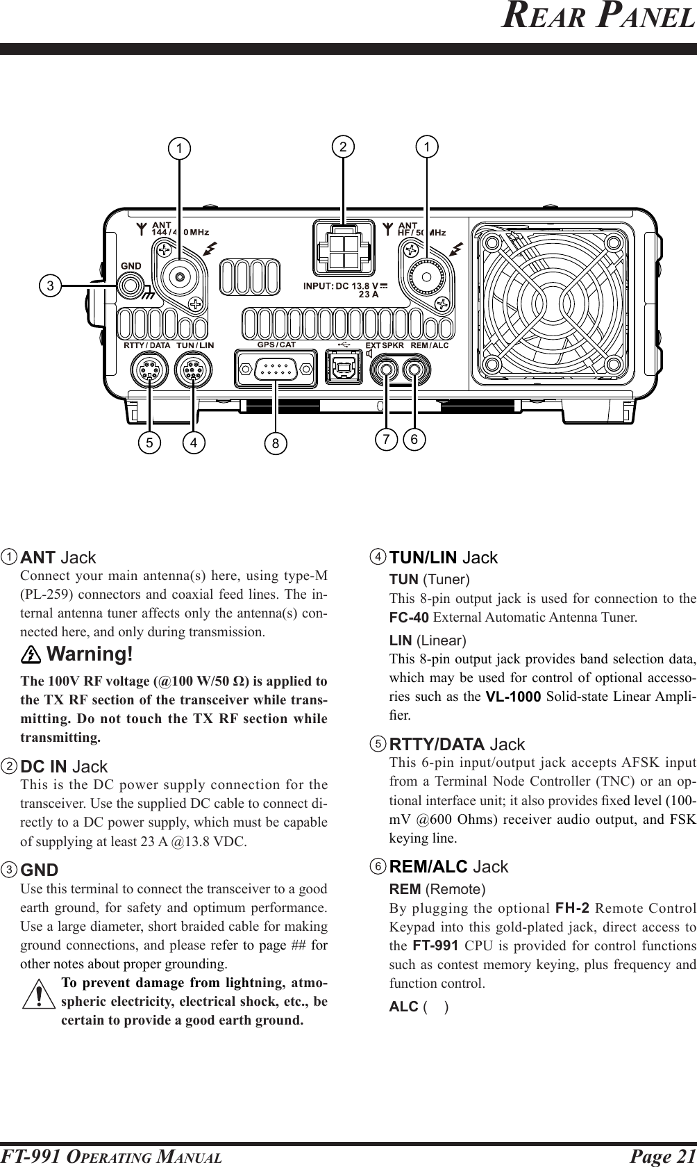
Yaesu Musen Co., Ltd. HF / VHF / UHF All Mode Transceiver 05 1 User Manual
Contents
- 1. Users Manual Part 1 Rev 1
- 2. Users Manual Part 2
- 3. TempConfidential_05_User_Manual_scope_function_only
Users Manual Part 1 Rev 1
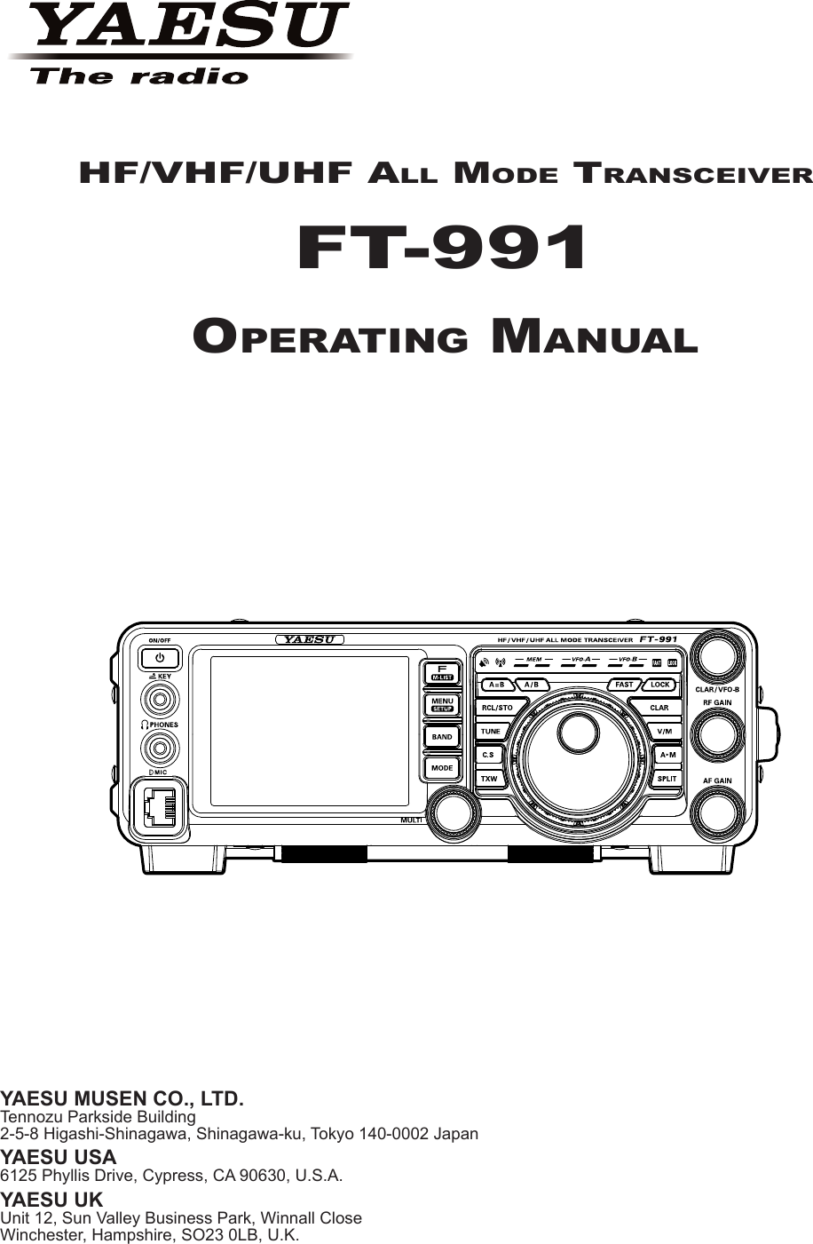
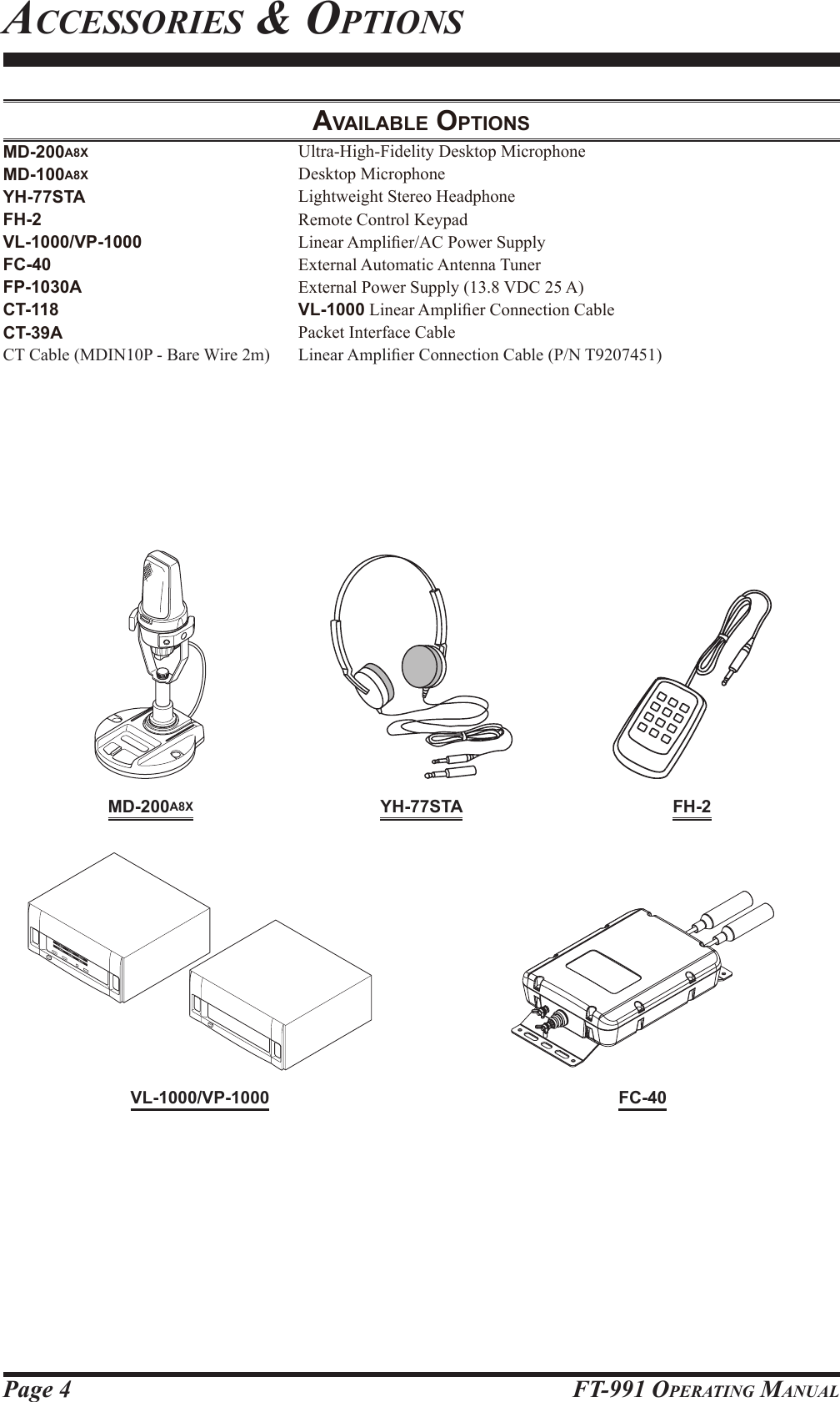
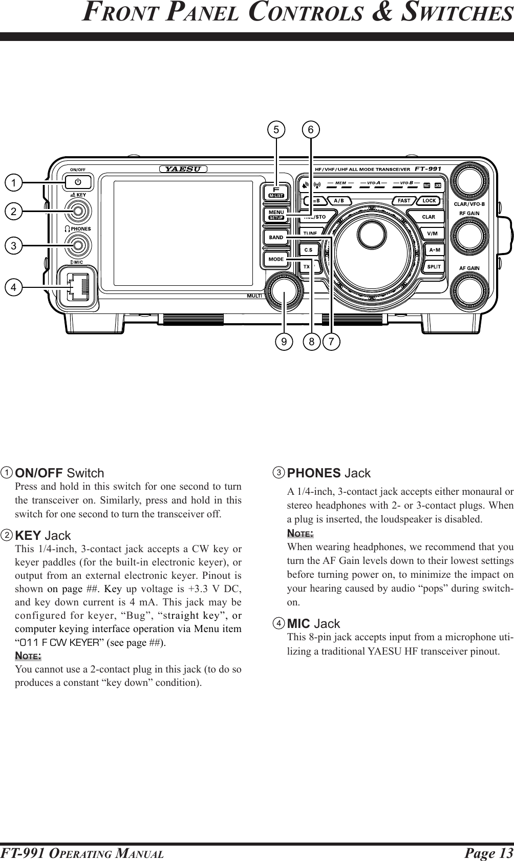
![Page 5FT-991 OperaTing ManualON/OFF switchMENU(SETUP) buttonAM buttonLCDbefore You beginreSetting the MicroproceSSorreSetting MeMorieS (only)Use this procedure to reset (clear) the previously stored Memory channels, without affecting any conguration changes you may have made to the Menu settings.1. Press the front panel ON/OFF switch to turn the transceiver off.2. While holding the AM button in, press and hold in the front panel ON/OFF switch to turn the trans-ceiver on. Once the transceiver comes on, you may release the buttons.Menu reSettingUse this procedure to restore the Menu settings to their factory defaults, without affecting the memories you have programmed.1. Press the front panel ON/OFF switch to turn the transceiver off.2. While holding the MENU(SETUP) button in, press and hold in the front panel ON/OFF switch to turn the transceiver on. Once the transceiver comes on, you may release the buttons.Full reSetUse this procedure to restore all Menu and Memory set-tings to their original factory defaults. All Memories will be cleared by this procedure.1. Press the front panel ON/OFF switch to turn the transceiver off.2. While holding the FAST and LOCK buttons in, press and hold in the front panel ON/OFF switch to turn the transceiver on. Once the transceiver comes on, you may release the buttons.LOCK buttonFAST buttonON/OFF switch MENU(SETUP) buttonON/OFF switchAdjuSting the clockUse the following procedure to adjust the clock shown at the top right of the LCD display.1. Press and hold the MENU(SETUP) button.2. Touch [TIME/DATE] on the LCD.3. Enter the present time with the number keys on the LCD, then touch [ENT].4. Touch [DATE] on the LCD to switch the screen.5. Enter month, day, and year with the number keys on the LCD, then touch [ENT].6. Touch [BACK] on the LCD to return to the setup mode display.7. Press the MENU(SETUP) button to return to the radio operation display.](https://usermanual.wiki/Yaesu-Musen/20575X50.Users-Manual-Part-1-Rev-1/User-Guide-2440474-Page-7.png)
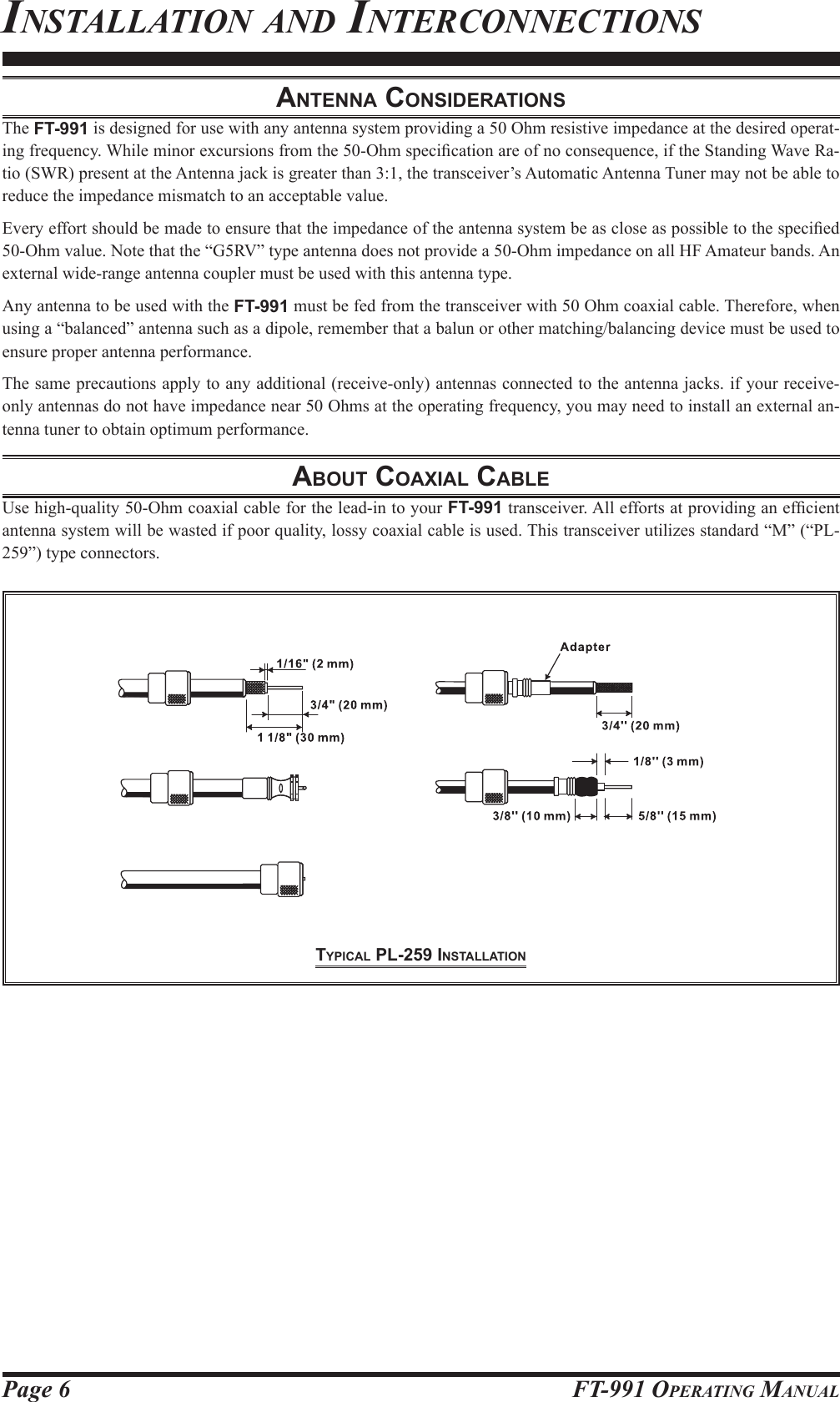
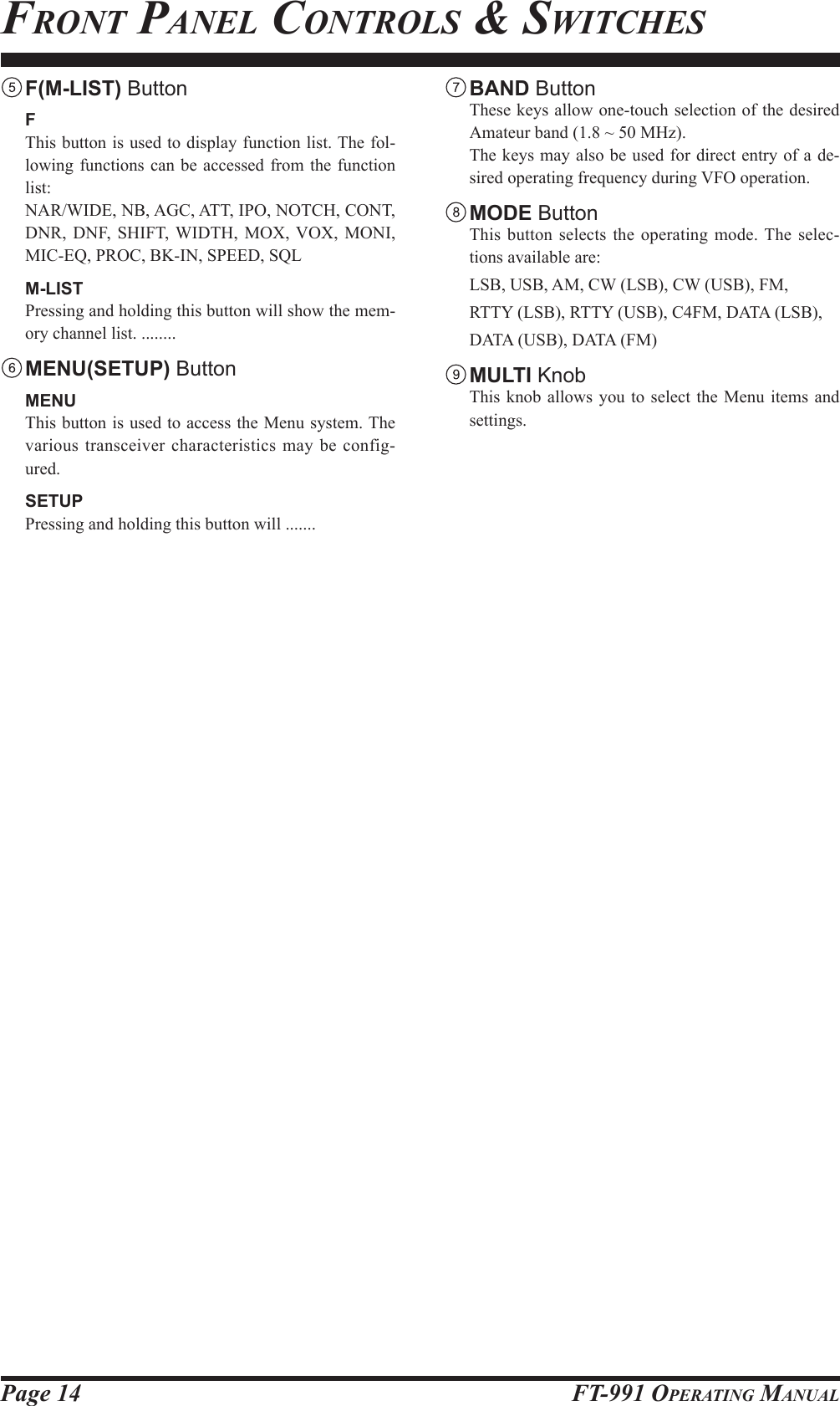
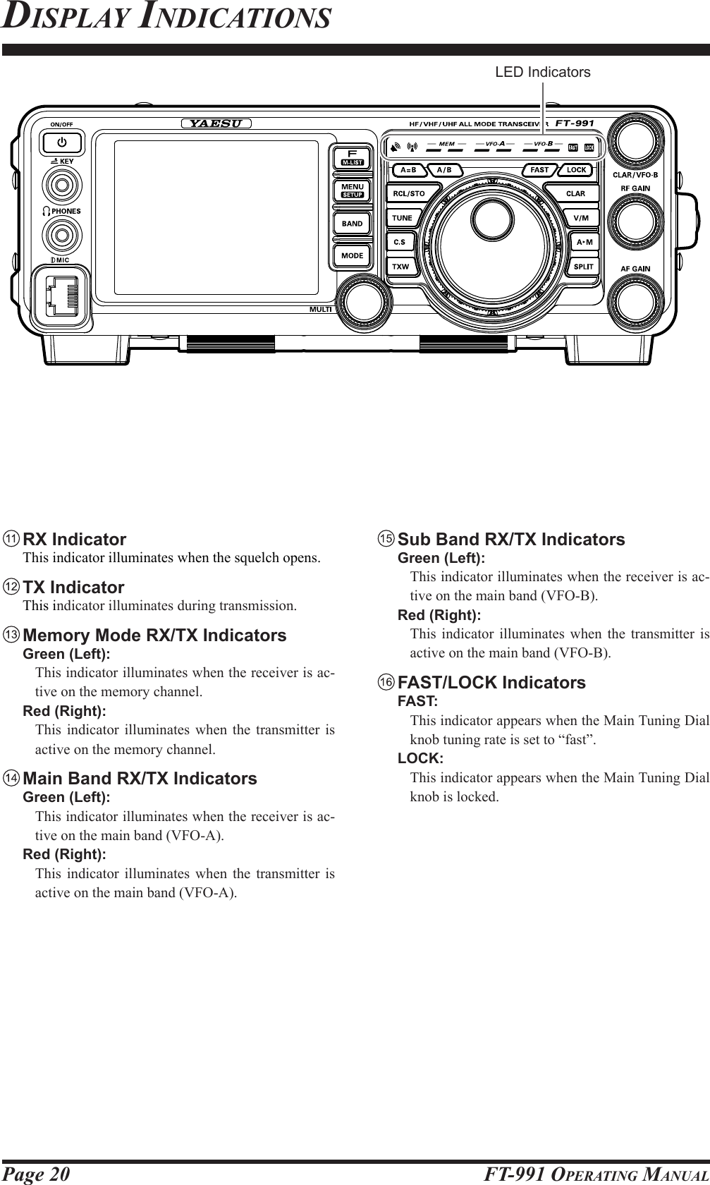
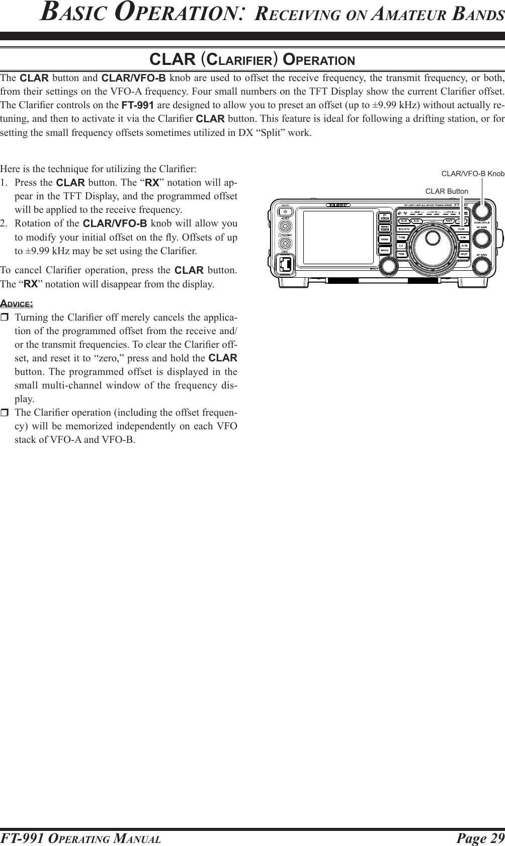
![Page 16 FT-991 OperaTing ManualfronT panel ConTrols & swiTChes C.S Button Press this button momentarily to directly recall a fa-vorite Menu Selection. To program a Menu selection to the C.S button, press the MENU(SETUP) button to enter the Menu. Select the Menu item you want to set as the short cut. Press the C.S button, then press the MENU(SETUP) button; this will lock in the select-ed Menu item as the short cut. TXW (TX Watch) Button Pressing and holding this button lets you monitor the transmit frequency when split frequency operation is engaged. Release the button to return to normal split frequency operation. FAST Button Pressing this button will change the tuning of the Main Tuning Dial knob (VFO-A) to a higher step rate. When this function is activated, the “FAST” indica-tor in the LED indicators area illuminates. LOCK Button This button toggles locking on/off for the Main Tun-ing Dial knob (VFO-A). With “Lock” on, the Main Tuning Dial knob can still be turned, but the fre-quency will not change, and the “LOCK” indicator in the LED indicators area illuminates. CLAR Button RX Pressing this button activates the RX Clarier. This will allow you to temporarily adjust the receive frequency up to ±9.999 kHz with the CLAR/VFO-B knob. Press this button once more to return the receiver to the original frequency; the Clarier offset will be remembered, in case you want to use it again. To cancel the Clarifier offset, press the [CLEAR] button. Pressing this switch during Split operation will change the tuning rate of the CLAR/VFO-B knob (VFO-B) to 100 Hz/step. When this function is activated, the “FAST” indica-tor in the LED indicators area illuminates. TX Pressing this button activates the TX Clarier, to al-low offsetting the transmit frequency temporarily. Press this button once more to return the transmit-ter to the original frequency; the Clarifier offset will be remembered, though, in case you want to use it again. To cancel the Clarier offset, press the [CLEAR] button. V/M Button This button toggles frequency control between VFO-A and the memory system. In memory mode, “MEM” (Memory Channel) will be shown in the display to indicate the current selection. Pressing the V/M but-ton displays the original memory frequency, and the “MEM” will be displayed. Pressing it once more returns frequency operation to VFO-A, and the icon will no longer be displayed. AM Button Pressing this button momentarily, displays the con-tents of the currently-selected memory channel for 10 seconds. Pressing and holding in this key for one second (until the double beep) copies the current operating data into the currently selected memory channel, over-writing any previous data stored there. SPLIT Button Press this button to operate split frequency between VFO-A (used for reception) and VFO-B (used for transmission). If you press and hold in the SPLIT button for one second, the “Quick Split” feature will be engaged. VFO-B transmit will automatically be set to a frequency 5 kHz higher than the VFO-A re-ceive frequency, with the same operating mode. The transceiver will operate in the Split mode.](https://usermanual.wiki/Yaesu-Musen/20575X50.Users-Manual-Part-1-Rev-1/User-Guide-2440474-Page-18.png)
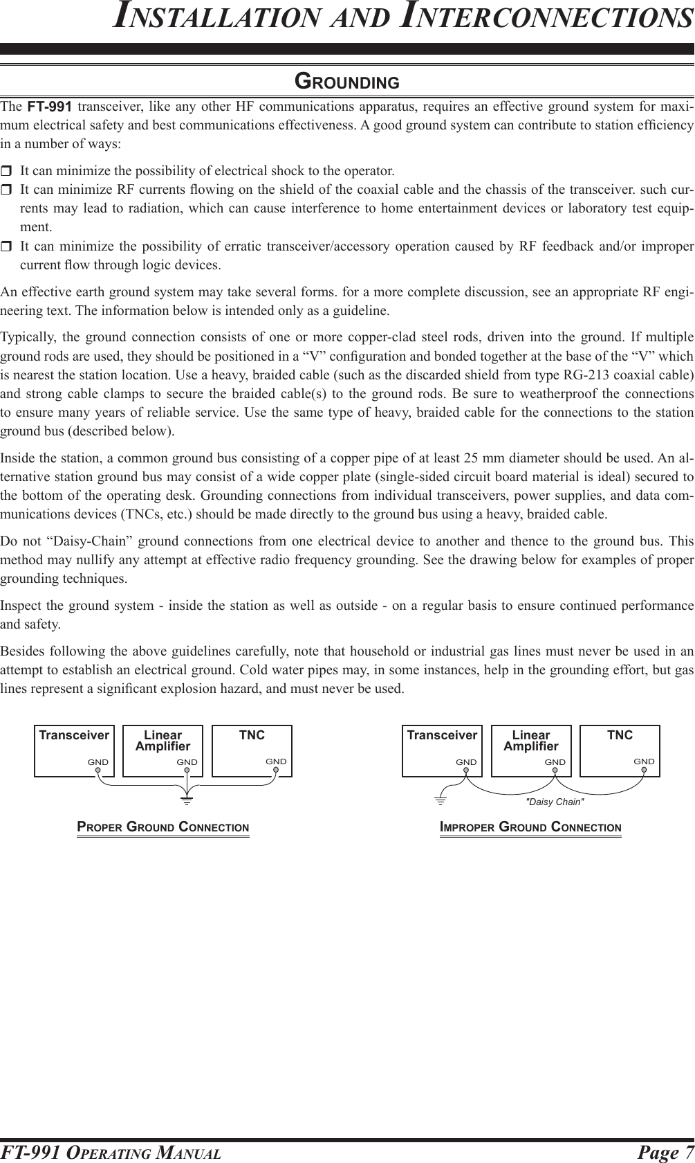
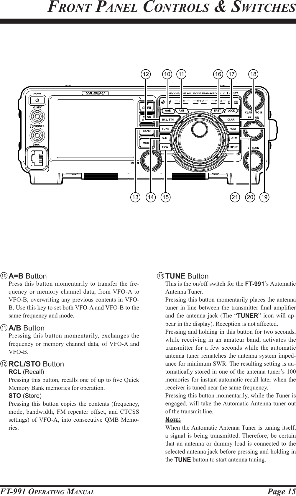
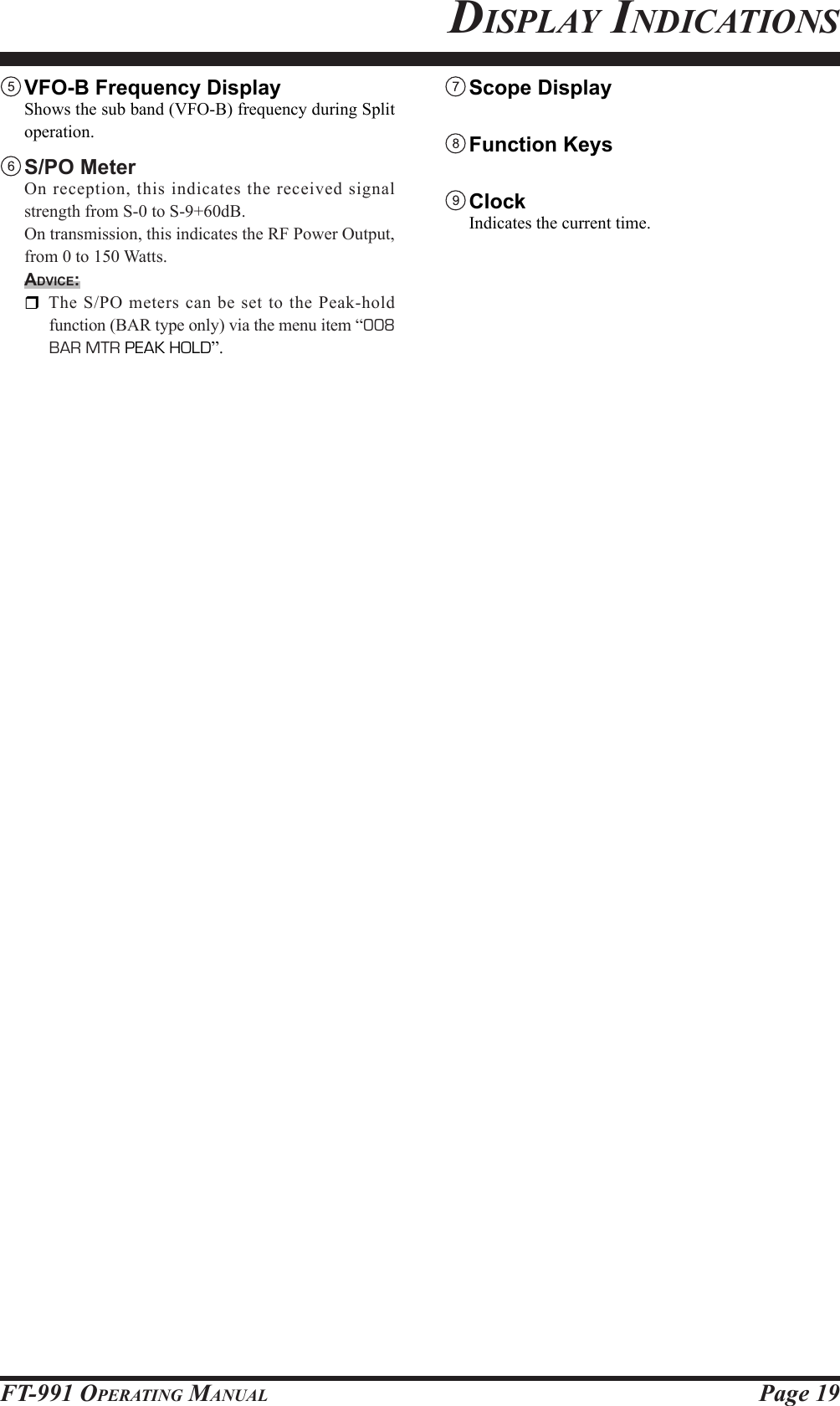
![Page 18 FT-991 OperaTing ManualdisplaY indiCaTions Mode Indicator Displays the current operating mode. VFO-A Frequency Display Shows the main band (VFO-A) frequency. Tuning Offset Indicator This indicates the relative offset of the CW-TUNE, μ-TUNE, Clarier, etc.CongurationIndicator TUNERThis indicator appears when the internal Automatic Antenna Tuner is activated. VOXThis indicator appears when the automatic voice-actuated transmitter switches in the SSB, AM, and FM modes. PROCThis indicator appears whenever the DSP Speech Processor is activated. MIC EQThis indicator appears whenever the Three-Band Parametric Microphone Equalizer is activated via the Menu. NARThis indicator appears whenever the receiver’s narrow IF DSP lter is engaged. RECThis indicator appears while the optional Voice Memory Unit is recording your voice message, or the Contest Keyer is recording your CW keying. PLAYThis indicator appears while the optional Voice Memory Unit is playing back the recorded voice message, or the recorded Contest CW keying. [+]/[-]During FM repeater operation, a negative frequen-cy shift will be indicated by “[-]” while a positive frequency shift will be indicated by “[+]”. DNRThis indicator appears whenever the Digital Noise Reduction feature is activated. DNFThis indicator appears whenever the Digital Notch Filter is activated.LCD Display](https://usermanual.wiki/Yaesu-Musen/20575X50.Users-Manual-Part-1-Rev-1/User-Guide-2440474-Page-20.png)
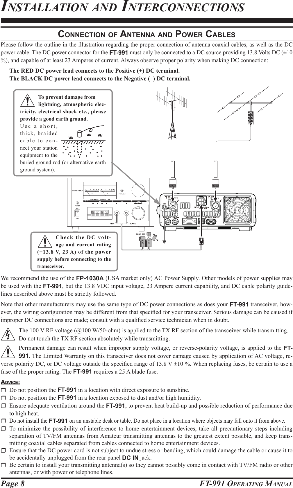
![Page 24 FT-991 OperaTing ManualopTional fh-2 swiTChesThe optional Remote Control Keypad FH-2 can be used to control the optional DVS-6 Voice Memory capability for the SSB/AM/FM modes; the contest memory keyer for the CW mode; and the text memory for the RTTY/DATA modes. Some specic capabilities of the FH-2 are:m On SSB/AM/FM modes, ve channels of storage and playback of voice memory (20 seconds each), using your own voice for recording (see page 71).m On CW mode, the FH-2 provides storage and recall of CW messages for repetitive CQ and contest automatic number transmissions (see page 85).m On RTTY/DATA mode, the FH-2 provides storage and recall of TEXT messages for repetitive CQ transmissions (see pages 104, 106). [1], [2], [3], [4], [5] ButtonsThese buttons work as the Voice Memory and CW Message Memory Selection Key.In the case of Voice Memory, up to 20 seconds of audio may be stored on each channel.For CW Messages and CW Text Messages, up to 50 characters ("PARIS" specification) may be stored into each channel. [t], [], [p], [q] ButtonsUsually, these buttons are used for tuning the VFO frequency. Press the [p]/[q] buttons to change the frequency in the same increments as the microphone [UP]/[DWN] switches. Press the [t]/[] buttons to change the frequency by 100 kHz steps.When programming the Contest Memory Keyer, these buttons are used to move the cursor and select the text characters. [P/B] ButtonThis button can be used to insert a space into the position where the cursor is blinking. [LOCK] ButtonThis button may be used to lock out the FH-2 key buttons, to prevent accidental activation of FH-2 operations. [MEM] ButtonPress this button to store either a Voice Memory, or a Contest Keyer Memory. [DEC] ButtonWhen utilizing the sequential contest number capability of the Contest Keyer, press this button to decrement (decrease) the current Contest Number by one digit (i.e. to back up from #198 to #197, etc.).](https://usermanual.wiki/Yaesu-Musen/20575X50.Users-Manual-Part-1-Rev-1/User-Guide-2440474-Page-26.png)
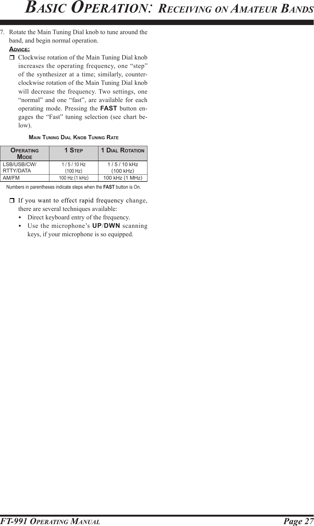
![Page 26 FT-991 OperaTing ManualAmateur band key may similarly have up to three frequency/mode settings applied. When [MHz] is touched, the “MHz” notation will appear in the display, and then rotation of the CLAR/VFO-B knob will change the frequency in 1 MHz steps.6. Press the MODE button to display the available se-lections. Touch the corresponding key to select the desired operating mode.Advice: By convention in the Amateur bands, LSB is used on the 7 MHz and lower bands (with the exception of 60 meters), while USB is utilized on the 14 MHz and higher bands. When changing modes from SSB to CW, you will observe a frequency shift on the display. This shift represents the BFO offset between the “zero beat” frequency and the audible CW pitch (tone) you can hear (the pitch is programmed via the Menu item “060 CW FREQ DISPLAY”), even though the actual tone that you hear is not chang-ing. When operating on the FM mode, repeatedly touch [SQL] (Squelch) on the screen displayed by pressing the F(M-LIST) button to point where the background noise is just silenced. This is the point of maximum sensitivity to weak signals. Excessive advancement of [SQL] will decrease the ability of the receiver to detect weak signals.1. Turn on the external DC power supply.2. Press and hold in the front-panel ON/OFF switch until the transceiver turns on. After about ve sec-onds, the transceiver is ready for full operation.3. The transceiver will start up on 7.000.00 MHz LSB, (or the previously used operating frequency) and normal operation may begin.note: To turn power off, press and hold in the front panel ON/OFF switch for one second.4. Rotate the AF GAIN knob to set a comfortable au-dio level of the incoming signals or noise. Clockwise rotation of the AF GAIN knob increases the volume level.note: When using headphones, start by rotating the AF GAIN knob counter-clockwise, then bring the vol-ume level up after you put the headphones on. This will minimize the chance of damage to your hearing caused by an unexpectedly high audio level.5. Press the BAND button to display the list of Amateur bands on the LCD, then touch a key corresponding to the band on which you wish to begin operation.Advice: One-touch selection of each Amateur band be-tween 1.8 and 50 MHz, 144 MHz, and 430 MHz is provided. The FT-991 utilizes a triple band-stack VFO selection technique, which permits storing up to three favorite frequencies and modes onto each VFO band register. For example, you may store one frequency each on 14 MHz CW, RTTY, and USB, then recall these frequencies by successive, momentary touches of the [14] on the screen displayed by pressing the BAND button. Each Here is the typical start-up procedure for normal operation: ON/OFF SwitchAF GAIN KnobMain Tuning Dial KnobBAND ButtonbasiC operaTion: reCeiving on aMaTeur bandsMODE Button](https://usermanual.wiki/Yaesu-Musen/20575X50.Users-Manual-Part-1-Rev-1/User-Guide-2440474-Page-28.png)
![Page 28 FT-991 OperaTing ManualoperAtion on 60-Meter (5 Mhz) bAnd (u.S. verSion only)The recently-released 60-meter band is covered, in the FT-991, by xed memory channels. These channels are set to USB or CW, and they appear between the “last” PMS channel (“P9U”) and the rst “regular” memory channel (Channel 1):1. Press the V/M button once to enter the “Memory” mode; the “MEM” icon will appear in the display.2. Touch [MCH] on the screen displayed by pressing the F(M-LIST) button. The “MCH” notation and a memory channel number will appear on the display to signify that rotation of the MULTI knob will allow selection of the memory channel.3. Memory channels (“501” through “510”) are pre-programmed, at the factory, with the permitted fre-quencies in the 5 MHz band, and the USB or CW mode is automatically selected on these channels.4. To exit from 60-meter operation and return to the VFO mode, just press the V/M button.note:The frequencies and operating mode for 5 MHz band operation are xed, and may not be changed.basiC operaTion: reCeiving on aMaTeur bandsV/M ButtonF(M-LIST) ButtonMULTI KnobMain Tuning Dial KnobchAnnelnuMber5015025035045055065075085095105.332000 MHz5.348000 MHz5.358500 MHz5.373000 MHz5.405000 MHz5.332000 MHz5.348000 MHz5.358500 MHz5.373000 MHz5.405000 MHzFrequency](https://usermanual.wiki/Yaesu-Musen/20575X50.Users-Manual-Part-1-Rev-1/User-Guide-2440474-Page-30.png)
![Page 30fT-991 operaTing ManualMULTI KnobMENU ButtonBackground colorbasiC operaTion: reCeiving on aMaTeur bandsLOCKYou may lock the setting of the Main Tuning Dial knob (for VFO-A frequency tuning) and the CLAR/VFO-B knob (for VFO-B frequency tuning during Split operation), to prevent accidental frequency change.Main Tuning Dial Knob LockTo lock the Main Tuning Dial knob, press the LOCK button that is located to the right of the Main Tuning Dial knob. To unlock the Dial setting, and restore nor-mal tuning, press the LOCK button once more.Advice:The lock feature will be memorized independently on the Main Tuning Dial knob and the CLAR/VFO-B knob.DIMMERThe illumination level of the TFT display and LED indicators (above the Main Tuning Dial knob), may be adjusted via Menu items 009 and 010.To adjust the illumination level:1. Press the MENU button to enter the Menu mode.2. Rotate the MULTI knob to select Menu item “006 DIMMER LED” (for LED indicators) or “007 DIM-MER TFT” (for TFT display).3. Touch [SELECT] on the LCD then rotate the MULTI knob to select the desired illumination level.4. Touch [ENTER] on the LCD, then touch [BACK] on the LCD or press the MENU button to save the new setting and exit to normal operation.MULTI KnobMENU ButtonVFO COLORThe background color of the VFO-A frequency in the TFT display may be selected via Menu item 007.1. Press the MENU button to enter the Menu mode.2. Rotate the MULTI knob to select Menu item “005 DISPLAY COLOR”.3. Touch [SELECT] on the LCD, then rotate the MULTI knob to select from the following colors: BLUE (default) / SKY BLUE / GREEN / PURPLE / RED / ORANGE / GRAY4. Touch [ENTER] on the LCD, then touch [BACK] on the LCD or press the MENU button to save the new setting and exit to normal operation.LOCK Button](https://usermanual.wiki/Yaesu-Musen/20575X50.Users-Manual-Part-1-Rev-1/User-Guide-2440474-Page-32.png)
![Page 31FT-991 OperaTing ManualConvenienCe FeaturesBand Stack OperatiOnThe FT-991 utilizes a triple band-stack VFO selection technique, that permits you to store up to three favorite frequen-cies and modes onto each band’s VFO register. For example, you may store one frequency each on 14 MHz CW, RTTY, and USB, then recall these VFOs by successive, momentary touches of [14] on the screen displayed by the BAND but-ton. Each Amateur band key may similarly have up to three frequency/mode settings applied. Note that only the VFO-A system has the band stacks.A typical setup, for the 14 MHz band, might be arranged like this:1. Program 14.025 MHz, CW Mode, press the BAND button, then touch [14] on the LCD;2. Program 14.080 MHz, RTTY Mode, press the BAND button, then touch [14] on the LCD;3. Program 14.195 MHz, SSB Mode, press the BAND button, then touch [14] on the LCD.With this conguration, successive momentary touches of [14] on the screen displayed by the BAND button will allow you to step sequentially through these three VFOs.c.S (cuStOm Switch)The front panel C.S button may be programmed to directly access an often-used Menu Mode selection.BAND ButtonC.S Setup1. Press the MENU button to engage the Menu mode; the Menu list will appear on the display.2. Rotate the MULTI knob to select the Menu item you want to access with the front panel C.S button.3. Press the C.S button to lock in your selection.4. Press the MENU button or touch [BACK] on the LCD to save the new conguration and exit to nor-mal operation.Menu Selection Recall via C.S buttonPress the C.S button.The programmed Menu item will appear on the display. Press the MENU button or touch [BACK] on the LCD exit to normal operation.MULTI KnobC.S buttonMENU button](https://usermanual.wiki/Yaesu-Musen/20575X50.Users-Manual-Part-1-Rev-1/User-Guide-2440474-Page-33.png)
![Page 32fT-991 operaTing ManualConvenienCe feaTuresScopeThis function displays a convenient spectrum scope for monitoring the band conditions. Both strong and weak signals can be displayed in an easy-to-understand manner on the TFT screen. This multifunctional scope takes into consid-eration the operator’s preference, by switching between the convenient CENTER mode where the VFO frequency is constantly in the center of the screen (for monitoring conditions on both sides of your operating frequency), and the FIX mode, where the frequency is xed to the left side of the screen (for convenience in monitoring in the band).Note: Since the FT-991 has only one receiver the audio will be muted while the spectrum scope is scanning.1. Press the [SCOPE] button momentarily to display the scope screen. Five different screens are shown on the TFT display by pressing the [SCOPE] button.Advice: During continuous sweeping, no audio will be heard.Full screen spectrum scope displaySCOPESpectrum scope display](https://usermanual.wiki/Yaesu-Musen/20575X50.Users-Manual-Part-1-Rev-1/User-Guide-2440474-Page-34.png)
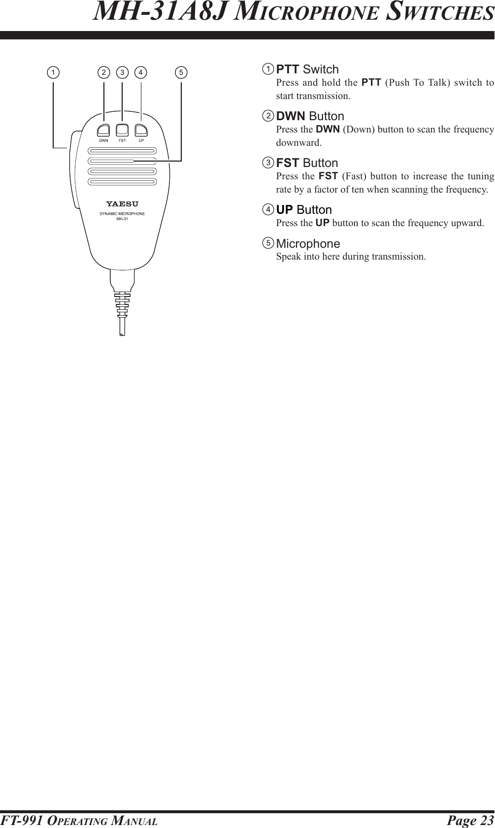
![Page 33FT-991 OperaTing ManualUsing the UP/DWN buttons of thesupplied MH-31A8J Hand MicrophoneThe UP/DWN buttons on the supplied MH-31A8J Hand Microphone may also be used to manually scan the fre-quency upward or downward.The microphone’s UP/DWN buttons utilize the tuning steps of the Main Tuning Dial knob.When the microphone FST button is pressed, the tuning rate increases by a factor of ten, in a manner similar to the transceiver front panel FAST button.Keyboard Frequency EntryThe Operating frequency may be entered directly into the current VFO, using the keyboard screen displayed by pressing the front panel BAND button.Example: Enter 14.250.00 MHz1. Press the BAND button to begin the direct frequency entry process. 2. Touch [ENT] on the LCD. The rst digit of the fre-quency (the leftmost digit) will blink.3. Enter, in order, the digits of the operating frequency, touching the keys on the LCD The decimal point after the “MHz” portion of the frequency must be entered, but no decimal point is required after the “kHz” portion.3. Touch [ENT] on the LCD once more to complete the operating frequency entry. A short “beep” will conrm that the entry was successful, and the new operating frequency will appear on the display.Advice: If you attempt to enter a frequency outside the oper-ating range of 30 kHz ~ 56 MHz, the microprocessor will ignore the attempt, and you will be returned to the previous operating frequency. If this happens, please try again, taking care not to repeat the error in the frequency entry process.More Frequency nAvigAtion techniqueSConvenienCe feaTures](https://usermanual.wiki/Yaesu-Musen/20575X50.Users-Manual-Part-1-Rev-1/User-Guide-2440474-Page-35.png)
![Page 35FT-991 OperaTing ManualinTerferenCe reJeCTionATT (AttenuAtor)When extremely strong local signals or high noise degrades reception, you can use [ATT] displayed by pressing the F(M-LIST) button to insert 6, 12, or 18-dB of RF attenuation in front of the RF amplier.1. Press the F(M-LIST) button, then touch [ATT] on the LCD several times to set the desired attenuation level, per the chart below.OFF: Attenuator is Off-6dB: The incoming signal power is reduced by 6 dB (Signal voltage reduced by 1/2)-12dB: The incoming signal power is reduced by 12 dB (Signal voltage reduced to 1/4) -18dB: The incoming signal power is reduced by 18 dB (Signal voltage reduced to 1/8) The selected attenuation level will be indicated in the ATT column of the Key Function Display on the TFT display.2. To restore full signal strength through the Attenuator circuit area, touch [ATT] on the LCD to restore the ATT display to the “OFF” position.Advice: If background noise causes a high S-meter indication on clear frequencies, touch [ATT] on the LCD until the S-meter drops to about “S-1”. This setting optimizes the trade-off between sensitivity, noise, and interference immu-nity. Also, once you have tuned in a station you want to work, you may want to reduce sensitivity further (add more attenuation) by touching [ATT] on the LCD to a higher setting. This reduces the strength of all signals (and noise) and can make reception more comfortable, important especially during long QSOs. When looking for weak signals on a quiet band, you will want maximum sensitivity, so the IPO should be disabled and [ATT] on the LCD should be set to “OFF.” This situation is typical during quiet times on frequencies above 21 MHz, and when using a small or negative-gain receiving antenna on other bands.F(M-LIST) Button](https://usermanual.wiki/Yaesu-Musen/20575X50.Users-Manual-Part-1-Rev-1/User-Guide-2440474-Page-37.png)
![Page 36 FT-991 OperaTing Manualipo (intercept point optiMizAtion)The IPO feature allows the operator to optimize the characteristics of the receiver front end, depending on the current noise level and the strength of incoming signals.Touch [IPO] displayed by pressing the F(M-LIST) but-ton repeatedly, to set the desired characteristic of the receiver front end, according to the chart below.AMP1: Amplies the incoming signals, using a low distortion RF preamplier (gain: approx. 10 dB).AMP2: Amplifies the incoming signals, using a 2-stage low-distortion RF preamplier (total gain: approx. 20 dB).IPO: Bypasses the RF preamplier, yielding direct feed to the rst mixer.The selected receiver RF preamplier will be indicated in the IPO column of the Key Function Display on the TFT display.Advice: On the 10 MHz and lower bands, it generally is not necessary to use any preamplier at all; selecting the “IPO” position as described above will increase the strong-signal-handling capability of the receiver, and generally will result in more pleasant reception due to reduced noise. If you can hear band noise with the preampliers disengaged, then a preamplier is gen-erally not needed.inTerferenCe reJeCTionF(M-LIST) Button](https://usermanual.wiki/Yaesu-Musen/20575X50.Users-Manual-Part-1-Rev-1/User-Guide-2440474-Page-38.png)
![Page 37FT-991 OperaTing ManualiF noiSe blAnker (nb) operAtionThe FT-991 includes an effective IF Noise Blanker, which can signicantly reduce noise caused by automotive ignition systems.1. Touch [NB] displayed by pressing the F(M-LIST) button briey to reduce short duration pulse noise such as from switching transients, automobile igni-tions and power lines. The “NB ON” will appear in the display to conrm that the Narrow-NB is operat-ing.2. Touch [NB] on the LCD again to reduce longer-duration man-made pulse noise. The “NBW ON” will appear in the display to conrm that the Wide-NB is operating.3. If desired, you may adjust the Noise Blanker level via Menu item “024 NB LEVEL” to the point where the offending noise is best reduced or eliminated. See box below for details.4. To end Noise Blanker operation, touch [NB] on the LCD once more. The “NB OFF” will appear in the display, conrming that the Noise Blanker is no lon-ger in operation.Adjusting the Noise Blanker Level1. Press the MENU button to engage the Menu mode.2. Rotate the MULTI knob to select Menu item “024 NB LEVEL”.3. Touch [SELECT] on the LCD4. Rotate the MULTI knob to the point where the offending noise is best reduced or eliminated.5. Touch [ENTER] on the LCD, then press the MENU button or touch [BACK] on the LCD to lock in the new setting and exit to normal opera-tion.inTerferenCe reJeCTionF(M-LIST) ButtonMULTI KnobMENU button](https://usermanual.wiki/Yaesu-Musen/20575X50.Users-Manual-Part-1-Rev-1/User-Guide-2440474-Page-39.png)
![Page 38 FT-991 OperaTing ManualinTerferenCe reJeCTioncontour control operAtionThe Contour lter system provides a gentle perturbation of the IF lter passband. The Contour is set to either suppress, or boost specic frequency components, and thus enhances the sound and readability of a received signal.1. Touch [CONT] displayed by pressing the F(M-LIST) button to activate the Contour lter. The DSP graphic display will illuminate and the current “null” (or “peak”) position of the Contour lter will appear in the CONTOUR indicator on the display.2. Rotate the MULTI knob to achieve the most natural-sounding audio reproduction on the incoming signal.Advice: The display will show the Contour frequency when-ever [CONT] on the LCD is touched.3. To cancel Contour tuning, touch [CONT] on the LCD.Advice: Alternate touches of [CONT] on the LCD will switch the Contour lter between on and off.Advice: The Contour lter level (either a null or a peak) may be adjusted using Menu item “112 CONTOUR LEV-EL”. The factory default setting is for a null of –15 (dB). The bandwidth over which the Contour lter effect is applied may be adjusted using Menu item “113 CONTOUR WIDTH”. The factory default setting is 10. When the set value is increased, the bandwidth becomes wider.Refer to Figure “B”, this illustrates an “inden-tation” of the Contour filter in the center of the passband. The Contour filter places a low-Q “notch” in the passband, per the settings of Menu items “112 CONTOUR LEVEL” and “113 CONTOUR WIDTH” (referenced above). Counter-clockwise rotation (to the left) of the MULTI knob causes the notch to move toward a lower frequency within the passband, while clockwise rotation (to the right) causes the notch to move toward a higher frequency within the passband. By removing interference or unwanted frequency components of the incoming signal, it is possible to make the desired signal rise out of the back-ground noise/interference, enhancing intelligibil-ity.quick point:By judicious use of the Contour lter, the “shoulder” of the passband response may be altered, or components may be removed from within the passband, allowing the desired signal to rise above the background noise and interference in a manner not obtainable with other ltering systems.IF BANDWIDTH IF BANDWIDTH IF BANDWIDTHMULTI MULTI MULTI A B CF(M-LIST) Button](https://usermanual.wiki/Yaesu-Musen/20575X50.Users-Manual-Part-1-Rev-1/User-Guide-2440474-Page-40.png)
![Page 39FT-991 OperaTing ManualIF BANDWIDTHDesired Signal Desired Signal Desired SignalQRMQRMIF BANDWIDTH IF BANDWIDTHMULTI MULTI MULTIinTerferenCe reJeCTioniF ShiFt operAtion (SSb/cw/rtty/pkt ModeS)IF SHIFT allows you to move the DSP lter passband higher or lower, without changing the pitch of the incoming sig-nal, and thus reduces or eliminates interference. Because the carrier tuning frequency is not varied, there is no need to re-tune the operating frequency to eliminate the interference. The total passband tuning range for the IF SHIFT system is ±1 kHz.1. Touch [SHIFT] displayed by pressing the F(M-LIST) button repeatedly to reduce the interference.Advice: The display will show the shift value of the IF SHIFT whenever [SHIFT] on the LCD is touched.Referring to Figure “A”, note the depiction of the IF DSP lter as the thick line, with MULTI knob in the 12 o’clock position. In Figure “B”, an in-terfering signal has appeared inside the original passband. In Figure “C”, you can see the effect of rotating the MULTI knob. The interference level is reduced by moving the lter passband so that the interference is outside of the passband. A B CF(M-LIST) Button](https://usermanual.wiki/Yaesu-Musen/20575X50.Users-Manual-Part-1-Rev-1/User-Guide-2440474-Page-41.png)
![Page 40 FT-991 OperaTing Manual A B CinTerferenCe reJeCTionwidth (iF dSp bAndwidth) tuning (SSb/cw/rtty/dAtA ModeS)The IF WIDTH tuning system allows you to vary the width of the DSP IF passband, to reduce or eliminate interference. Moreover, the bandwidth may actually be expanded from its default setting, should you wish to enhance incoming sig-nal delity when interference on the band is low.1. Touch [WIDTH] displayed by pressing the F(M-LIST) button repeatedly to reduce the interference.Advice: The frequency display will show the bandwidth of the IF passband whenever [WIDTH] is touched.Referring to Figure “B”, you can see the default bandwidth on the SSB mode.By rotating the MULTI knob to the left, the band-width will narrow (see Figure “A”, while rotation of the MULTI knob to the right, as depicted in Figure “C”, will increase the bandwidth. A B CThe default bandwidths, and total bandwidth ad-justment range, will vary according to the operat-ing mode:SSB Mode: 1.8 kHz ~ 4.0 kHz (default: 2.4 kHz).CW Mode: 500 Hz ~ 2.4 kHz (default: 2.4 kHz)RTTY/DATA Modes: 500 Hz ~ 2.4 kHz (default: 500 Hz)Using IF SHIFT and WIDTH TogetherThe IF SHIFT and Variable IF WIDTH features together form a very effective interference-ght-ing ltering system.For example, in Figure “A”, you can see how in-terference has appeared both on the high and low sides of the desired signal. Touch [WIDTH] on the LCD, the interference from one side can be eliminated (Figure “B”). Next, rotate the MULTI knob to re-position the passband (Figure “C”), the interference on the opposite side can be re-moved, without re-introducing the interference previously eliminated in Figure “B”.Advice: For best interference reduction, the WIDTH and SHIFT features are the primary tools you should use, after narrowing the bandwidth (WIDTH) and/or adjusting the center of the passband (SHIFT). The Contour control may then yield additional signal-enhancement benefits on the net residual bandwidth. Even more, the IF NOTCH Filter (described later) may also be used, in conjunction with these lter systems, to signicant advantage.IF BANDWIDTH IF BANDWIDTH IF BANDWIDTHMULTI MULTI MULTI Desired Signal Desired Signal Desired SignalQRMQRMQRMQRMQRMQRMIF BANDWIDTH IF BANDWIDTH IF BANDWIDTHF(M-LIST) Button](https://usermanual.wiki/Yaesu-Musen/20575X50.Users-Manual-Part-1-Rev-1/User-Guide-2440474-Page-42.png)
![Page 41FT-991 OperaTing ManualoperAting Mode SSB CW RTTY/DATA AMFM (28/50/144/430 MHz Bands)inTerferenCe reJeCTionnArrow (nAr) one-touch iF Filter SelectionTouching [NAR/WIDE] displayed by pressing the F(M-LIST) button provides one-touch, mode-specic, selection of a narrow IF DSP lter setting that does not require resetting the bandwidth control to the WIDTH/SHIFT system.Touching [NAR/WIDE] on the LCD once more returns the bandwidth control to the WIDTH/SHIFT system. The factory default bandwidths are:: Depends on the [WIDTH] setting( ): Default Bandwidth “on”200 Hz ~ 1.8 kHz (1.5 kHz)50 ~ 500 Hz (500 Hz)50 ~ 500 Hz (300 Hz)6 kHz9 kHz “oFF”1.8 ~ 3.0 kHz (2.4 kHz)500 Hz ~ 3.0 kHz (2.4 kHz)500 Hz ~ 2.4 kHz (500 Hz)9 kHz16 kHz [nAr/wide] touch keyAdvice: When the narrow bandwidth is selected, the “NAR” icon will appear in the display. If [NAR/WIDE] on the LCD has been touched to engage the narrow lter, you may still adjust the nar-row IF bandwidth with [WIDTH] on the LCD and the MULTI knob. The IF SHIFT is also operational. When you touch [NAR/WIDE] on the LCD in the FM mode, both transmit and receive bandwidths are narrowed.F(M-LIST) Button](https://usermanual.wiki/Yaesu-Musen/20575X50.Users-Manual-Part-1-Rev-1/User-Guide-2440474-Page-43.png)