Yaesu Musen 20575X50 HF / VHF / UHF All Mode Transceiver User Manual 05 1 User Manual
Yaesu Musen Co., Ltd. HF / VHF / UHF All Mode Transceiver 05 1 User Manual
Contents
- 1. Users Manual Part 1 Rev 1
- 2. Users Manual Part 2
- 3. TempConfidential_05_User_Manual_scope_function_only
Users Manual Part 1 Rev 1

HF/VHF/UHF All Mode TrAnsceiVer
FT-991
operATing MAnUAl
YAESU MUSEN CO., LTD.
Tennozu Parkside Building
2-5-8 Higashi-Shinagawa, Shinagawa-ku, Tokyo 140-0002 Japan
YAESU USA
6125 Phyllis Drive, Cypress, CA 90630, U.S.A.
YAESU UK
Unit 12, Sun Valley Business Park, Winnall Close
Winchester, Hampshire, SO23 0LB, U.K.

Page 1
FT-991 OperaTing Manual
Table of ConTenTs
Table of Contents ......................................................... 1
Accessories & Options ................................................. 3
Supplied Accessories ................................................ 3
Available Options ..................................................... 4
Adjusting the Clock .................................................. 5
Resetting the Microprocessor ................................... 5
Installation and Interconnections ............................... 6
Antenna Considerations ........................................... 6
About Coaxial Cable ................................................ 6
Grounding ................................................................. 7
Connection of Antenna and Power Cables ............... 8
Connection of Microphone and Headphone ............. 9
Key, Keyer, and Computer-Driven Keying
Interconnections ..................................................... 10
VL-1000 Linear Amplier Interconnections .......... 11
Interfacing to Other Linear Ampliers ................... 12
Front Panel Controls & Switches ............................. 13
Display Indications..................................................... 18
Rear Panel ................................................................... 21
MH-31A8J Microphone Switches ............................. 23
Optional FH-2 Switches ............................................. 24
Basic Operation: Receiving on Amateur Bands ...... 25
Operation on 60-Meter (5 MHz) Band (U.S. version
only) ....................................................................... 28
CLAR (Clarier) Operation ................................... 29
LOCK ..................................................................... 30
DIMMER ............................................................... 30
VFO COLOR ......................................................... 30
Band Stack Operation ............................................. 31
C.S (Custom Switch) .............................................. 31
Convenience Features ................................................ 31
SCOPE ................................................................... 32
More Frequency Navigation Techniques ............... 33
Receiver Operation (Front End Block Diagram) ... 34
ATT (AttenuAtor) .................................................. 35
Interference Rejection ............................................... 35
IPO (Intercept Point Optimization) ........................ 36
IF Noise Blanker (NB) Operation .......................... 37
CONTOUR Control Operation .............................. 38
IF SHIFT Operation (SSB/CW/RTTY/PKT
Modes) .................................................................... 39
WIDTH (IF DSP Bandwidth) Tuning (SSB/CW/
RTTY/DATA Modes) ............................................. 40
NARROW (NAR) One-Touch IF Filter
Selection ................................................................. 41
IF NOTCH Filter Operation (SSB/CW/RTTY/
DATA/AM Modes) ................................................. 42
Digital NOTCH Filter (DNF) Operation ................ 43
Digital Noise Reduction (DNR) Operation ............ 43
Tools for Comfortable and Effective Reception ...... 44
RF Gain .................................................................. 44
Audio Peak Filter ................................................... 45
AGC (Automatic Gain Control) ............................. 46
Adjustable Receiver Audio Filter ........................... 47
SSB/AM Mode Transmission .................................... 48
ATU Operation ....................................................... 50
Using the Automatic Antenna Tuner ........................ 50
About ATU Operation ............................................ 51
PArAmetric microphone equAlizer (SSB/Am/Fm
mode) ...................................................................... 52
Enhancing Transmit Signal Quality ......................... 52
Using the Speech Processor (SSB Mode) .............. 54
Adjusting the SSB Transmitted Bandwidth (SSB
Mode) ..................................................................... 55
Voice Memory (SSB/AM/FM modes: Requires
optional DVS-6 and FH-2) ................................ 56
Transmitter Convenience Features .......................... 56
VOX (SSB/AM/FM Modes: Automatic TX/RX
Switching using Voice Control) ............................. 58
MONITOR (SSB/AM/FM modes) ......................... 59
Split-Frequency Operation ..................................... 60
Setup for Straight Key (and Straight Key emulation)
Operation ................................................................ 61
CW Mode Operation ................................................. 61
Using the Built-in Electronic Keyer ....................... 62
CW Spotting (Zero-Beating) .................................. 65
CW Convenience Features ........................................ 65
CW Delay Time Setting ......................................... 66
Contest Memory Keyer (Using the Optional FH-2
Remote Control Keypad) ....................................... 67
Basic Operation ...................................................... 72

Page 2 FT-991 OperaTing Manual
Table of ConTenTs
FM Mode Operation .................................................. 72
Repeater Operation ................................................. 73
Tone Squelch Operation ......................................... 74
Memory Operation .................................................... 75
Convenient Memory functions ............................... 75
QMB (Quick Memory Bank) ................................. 75
Standard Memory Operation .................................. 76
Memory Groups ..................................................... 80
Operation on Alaska Emergency Frequency: 5167.5
khz (U.S. Version Only) ............................................. 81
VFO and Memory Scanning ..................................... 82
VFO Scanning ........................................................ 82
Memory Scan ......................................................... 83
PMS (Programmable Memory Scanning) ............... 84
RTTY (Radio Teletype) Operation ........................... 85
Example of Connecting RTTY Communications
Device ..................................................................... 85
DATA (PSK) Operation ............................................. 86
Example of Data Communications Device ........... 86
Menu Mode ................................................................. 87
Specications .............................................................. 91

Page 3
FT-991 OperaTing Manual
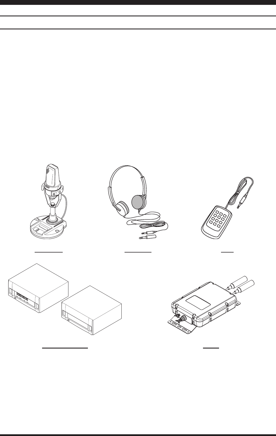
aCCessories & opTions
Supplied AcceSSorieS
Hand Microphone (MH-31A8J) 1 pc A07890001
DC Power Cord 1 pc T9025225
Spare Fuse (25A) 1 pc Q0000074
Operating Manual 1 pc
Warranty Card 1 pc
Page 4 FT-991 OperaTing Manual
Accessories & options
AvAilAble OptiOns
MD-200A8X Ultra-High-Fidelity Desktop Microphone
MD-100A8X Desktop Microphone
YH-77STA Lightweight Stereo Headphone
FH-2 Remote Control Keypad
VL-1000/VP-1000 LinearAmplier/ACPowerSupply
FC-40 ExternalAutomaticAntennaTuner
FP-1030A ExternalPowerSupply(13.8VDC25A)
CT-118 VL-1000LinearAmplierConnectionCable
CT-39A PacketInterfaceCable
CTCable(MDIN10P-BareWire2m) LinearAmplierConnectionCable(P/NT9207451)
MD-200A8X YH-77STA FH-2
VL-1000/VP-1000 FC-40
Page 5
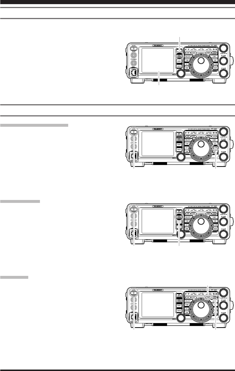
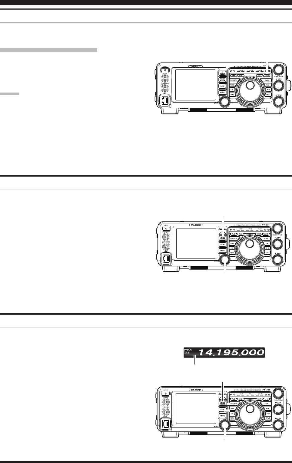
FT-991 OperaTing Manual
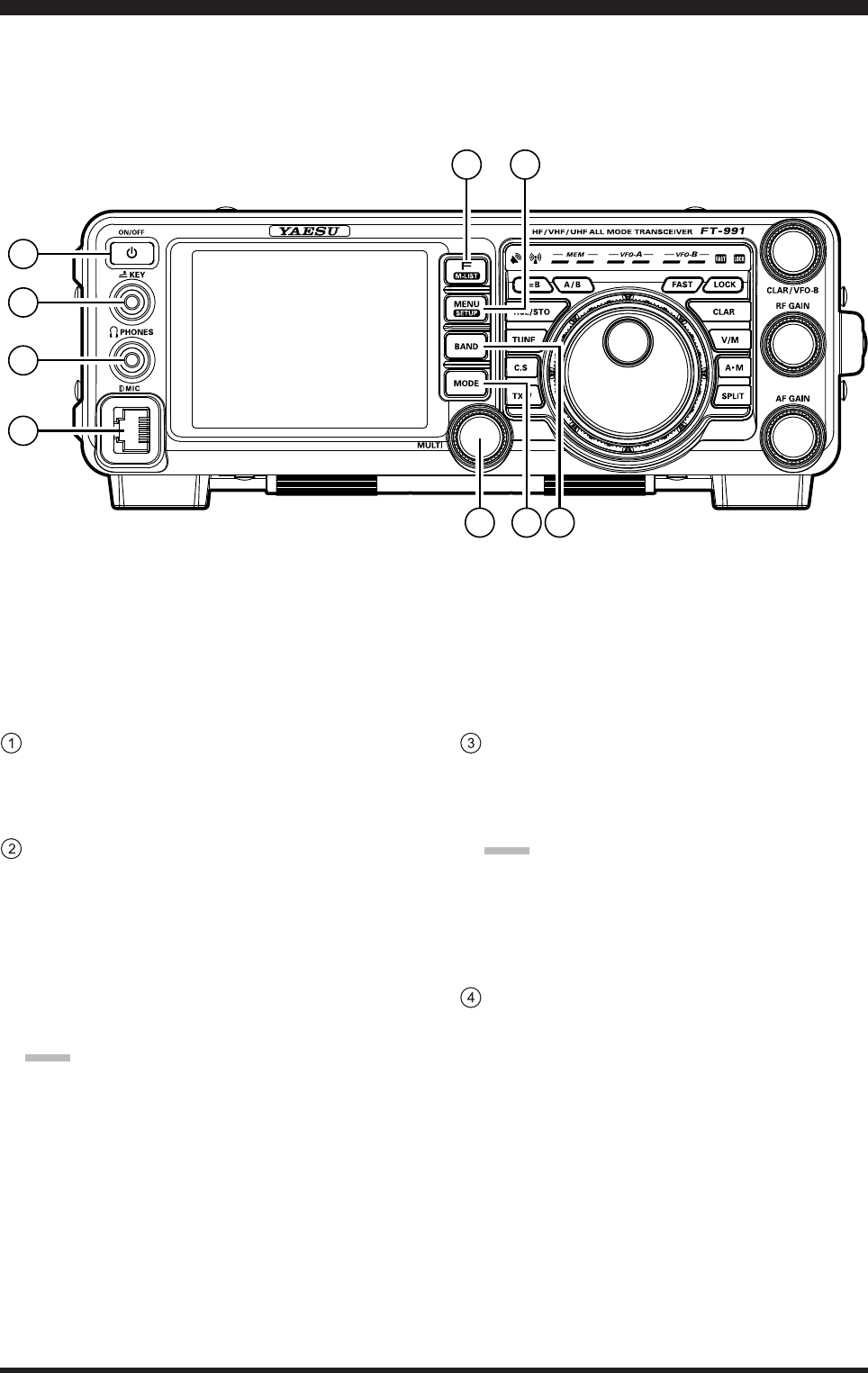
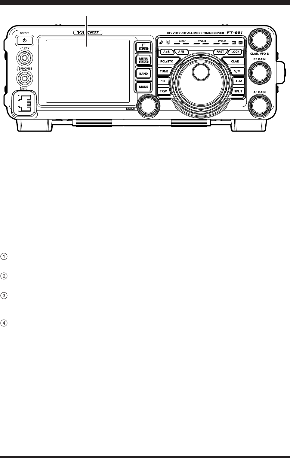
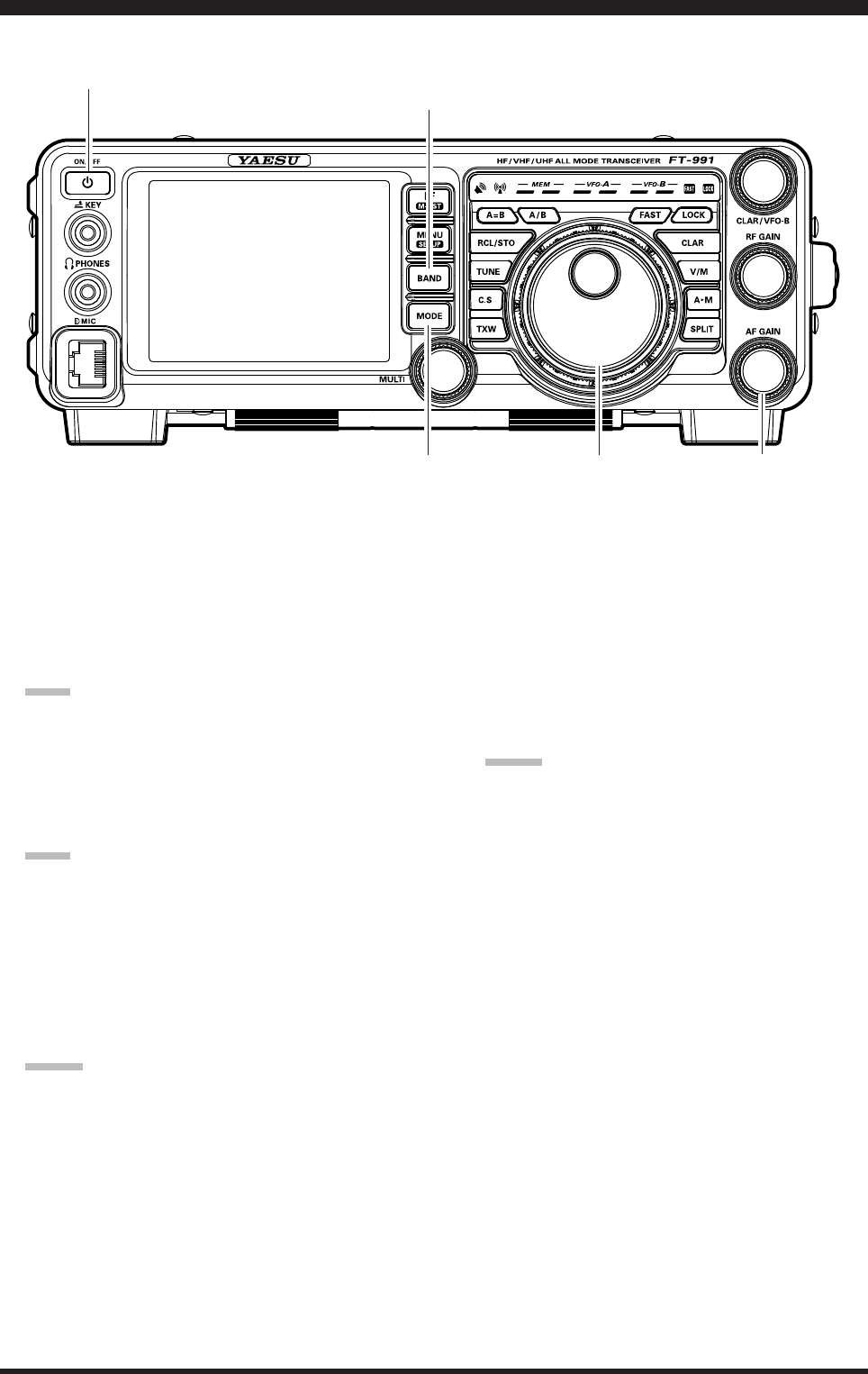
ON/OFF switch
MENU(SETUP) button
A
M button
LCD
before You begin
reSetting the MicroproceSSor
reSetting MeMorieS (only)
Use this procedure to reset (clear) the previously stored
Memory channels, without affecting any conguration
changes you may have made to the Menu settings.
1. Press the front panel ON/OFF switch to turn the
transceiver off.
2. While holding the A
M button in, press and hold
in the front panel ON/OFF switch to turn the trans-
ceiver on. Once the transceiver comes on, you may
release the buttons.
Menu reSetting
Use this procedure to restore the Menu settings to their
factory defaults, without affecting the memories you
have programmed.
1. Press the front panel ON/OFF switch to turn the
transceiver off.
2. While holding the MENU(SETUP) button in, press
and hold in the front panel ON/OFF switch to turn
the transceiver on. Once the transceiver comes on,
you may release the buttons.
Full reSet
Use this procedure to restore all Menu and Memory set-
tings to their original factory defaults. All Memories will
be cleared by this procedure.
1. Press the front panel ON/OFF switch to turn the
transceiver off.
2. While holding the FAST and LOCK buttons in,
press and hold in the front panel ON/OFF switch to
turn the transceiver on. Once the transceiver comes
on, you may release the buttons.
LOCK button
FAST button
ON/OFF switch MENU(SETUP) button
ON/OFF switch
AdjuSting the clock
Use the following procedure to adjust the clock shown at the top right of the LCD display.
1. Press and hold the MENU(SETUP) button.
2. Touch [TIME/DATE] on the LCD.
3. Enter the present time with the number keys on the
LCD, then touch [ENT].
4. Touch [DATE] on the LCD to switch the screen.
5. Enter month, day, and year with the number keys on
the LCD, then touch [ENT].
6. Touch [BACK] on the LCD to return to the setup
mode display.
7. Press the MENU(SETUP) button to return to the
radio operation display.
Page 6 FT-991 OperaTing Manual
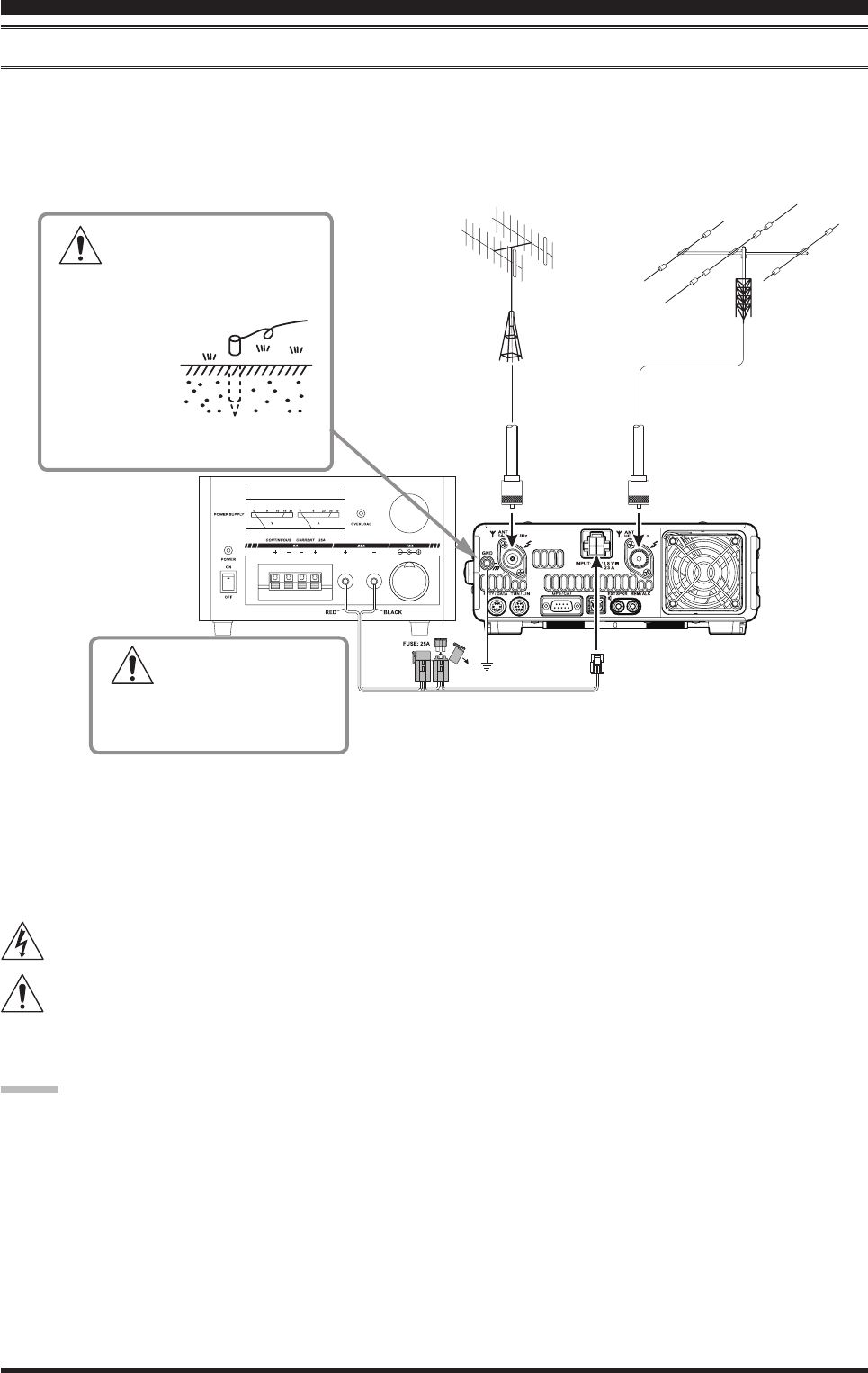
AntennA conSiderAtionS
The FT-991 is designed for use with any antenna system providing a 50 Ohm resistive impedance at the desired operat-
ing frequency. While minor excursions from the 50-Ohm specication are of no consequence, if the Standing Wave Ra-
tio (SWR) present at the Antenna jack is greater than 3:1, the transceiver’s Automatic Antenna Tuner may not be able to
reduce the impedance mismatch to an acceptable value.
Every effort should be made to ensure that the impedance of the antenna system be as close as possible to the specied
50-Ohm value. Note that the “G5RV” type antenna does not provide a 50-Ohm impedance on all HF Amateur bands. An
external wide-range antenna coupler must be used with this antenna type.
Any antenna to be used with the FT-991 must be fed from the transceiver with 50 Ohm coaxial cable. Therefore, when
using a “balanced” antenna such as a dipole, remember that a balun or other matching/balancing device must be used to
ensure proper antenna performance.
The same precautions apply to any additional (receive-only) antennas connected to the antenna jacks. if your receive-
only antennas do not have impedance near 50 Ohms at the operating frequency, you may need to install an external an-
tenna tuner to obtain optimum performance.
About coAxiAl cAble
Use high-quality 50-Ohm coaxial cable for the lead-in to your FT-991 transceiver. All efforts at providing an efcient
antenna system will be wasted if poor quality, lossy coaxial cable is used. This transceiver utilizes standard “M” (“PL-
259”) type connectors.
insTallaTion and inTerConneCTions
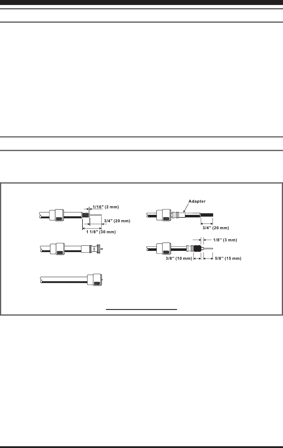
typicAl pl-259 inStAllAtion
Page 7
FT-991 OperaTing Manual
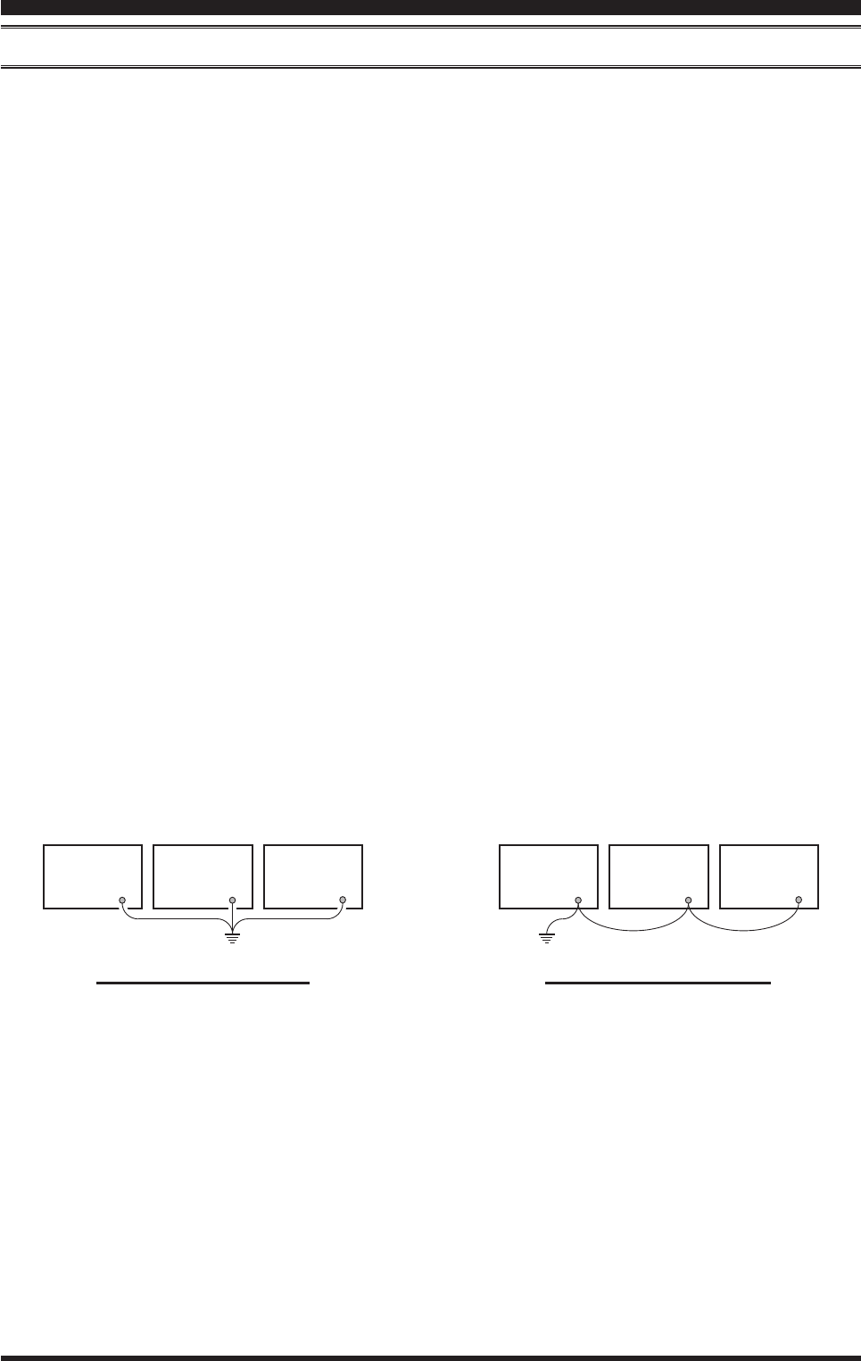
insTallaTion and inTerConneCTions
proper ground connection
GND
Linear
Amplifier
GND
TNC
GND
Transceiver
GND
Transceiver
GND
Linear
Amplifier
GND
TNC
"Daisy Chain"
GND
Linear
Amplifier
GND
TNC
GND
Transceiver
GND
Transceiver
GND
Linear
Amplifier
GND
TNC
"Daisy Chain"
iMproper ground connection
grounding
The FT-991 transceiver, like any other HF communications apparatus, requires an effective ground system for maxi-
mum electrical safety and best communications effectiveness. A good ground system can contribute to station efciency
in a number of ways:
It can minimize the possibility of electrical shock to the operator.
It can minimize RF currents owing on the shield of the coaxial cable and the chassis of the transceiver. such cur-
rents may lead to radiation, which can cause interference to home entertainment devices or laboratory test equip-
ment.
It can minimize the possibility of erratic transceiver/accessory operation caused by RF feedback and/or improper
current ow through logic devices.
An effective earth ground system may take several forms. for a more complete discussion, see an appropriate RF engi-
neering text. The information below is intended only as a guideline.
Typically, the ground connection consists of one or more copper-clad steel rods, driven into the ground. If multiple
ground rods are used, they should be positioned in a “V” conguration and bonded together at the base of the “V” which
is nearest the station location. Use a heavy, braided cable (such as the discarded shield from type RG-213 coaxial cable)
and strong cable clamps to secure the braided cable(s) to the ground rods. Be sure to weatherproof the connections
to ensure many years of reliable service. Use the same type of heavy, braided cable for the connections to the station
ground bus (described below).
Inside the station, a common ground bus consisting of a copper pipe of at least 25 mm diameter should be used. An al-
ternative station ground bus may consist of a wide copper plate (single-sided circuit board material is ideal) secured to
the bottom of the operating desk. Grounding connections from individual transceivers, power supplies, and data com-
munications devices (TNCs, etc.) should be made directly to the ground bus using a heavy, braided cable.
Do not “Daisy-Chain” ground connections from one electrical device to another and thence to the ground bus. This
method may nullify any attempt at effective radio frequency grounding. See the drawing below for examples of proper
grounding techniques.
Inspect the ground system - inside the station as well as outside - on a regular basis to ensure continued performance
and safety.
Besides following the above guidelines carefully, note that household or industrial gas lines must never be used in an
attempt to establish an electrical ground. Cold water pipes may, in some instances, help in the grounding effort, but gas
lines represent a signicant explosion hazard, and must never be used.
Page 8 FT-991 OperaTing Manual
connection oF AntennA And power cAbleS
Please follow the outline in the illustration regarding the proper connection of antenna coaxial cables, as well as the DC
power cable. The DC power connector for the
FT-991
must only be connected to a DC source providing 13.8 Volts DC (±10
%), and capable of at least 23 Amperes of current. Always observe proper polarity when making DC connection:
The RED DC power lead connects to the Positive (+) DC terminal.
The BLACK DC power lead connects to the Negative (–) DC terminal.
We recommend the use of the FP-1030A (USA market only) AC Power Supply. Other models of power supplies may
be used with the FT-991, but the 13.8 VDC input voltage, 23 Ampere current capability, and DC cable polarity guide-
lines described above must be strictly followed.
Note that other manufacturers may use the same type of DC power connections as does your FT-991 transceiver, how-
ever, the wiring conguration may be different from that specied for your transceiver. Serious damage can be caused if
improper DC connections are made; consult with a qualied service technician when in doubt.
The 100 V RF voltage (@100 W/50-ohm) is applied to the TX RF section of the transceiver while transmitting.
Do not touch the TX RF section absolutely while transmitting.
Permanent damage can result when improper supply voltage, or reverse-polarity voltage, is applied to the FT-
991. The Limited Warranty on this transceiver does not cover damage caused by application of AC voltage, re-
verse polarity DC, or DC voltage outside the specied range of 13.8 V ±10 %. When replacing fuses, be certain to use a
fuse of the proper rating. The FT-991 requires a 25 A blade fuse.
Advice:
Do not position the FT-991 in a location with direct exposure to sunshine.
Do not position the FT-991 in a location exposed to dust and/or high humidity.
Ensure adequate ventilation around the FT-991, to prevent heat build-up and possible reduction of performance due
to high heat.
Do not install the
FT-991
on an unstable desk or table. Do not place in a location where objects may fall onto it from above.
To minimize the possibility of interference to home entertainment devices, take all precautionary steps including
separation of TV/FM antennas from Amateur transmitting antennas to the greatest extent possible, and keep trans-
mitting coaxial cables separated from cables connected to home entertainment devices.
Ensure that the DC power cord is not subject to undue stress or bending, which could damage the cable or cause it to
be accidentally unplugged from the rear panel DC IN jack.
Be certain to install your transmitting antenna(s) so they cannot possibly come in contact with TV/FM radio or other
antennas, or with power or telephone lines.
insTallaTion and inTerConneCTions
Check the DC volt-
age and current rating
(+13.8 V, 23 A) of the power
supply before connecting to the
transceiver.
To prevent damage from
lightning, atmospheric elec-
tricity, electrical shock etc., please
provide a good earth ground.
Use a short,
thick, braided
cable to con-
nect your station
equipment to the
buried ground rod (or alternative earth
ground system).
Page 9
FT-991 OperaTing Manual
insTallaTion and inTerConneCTions
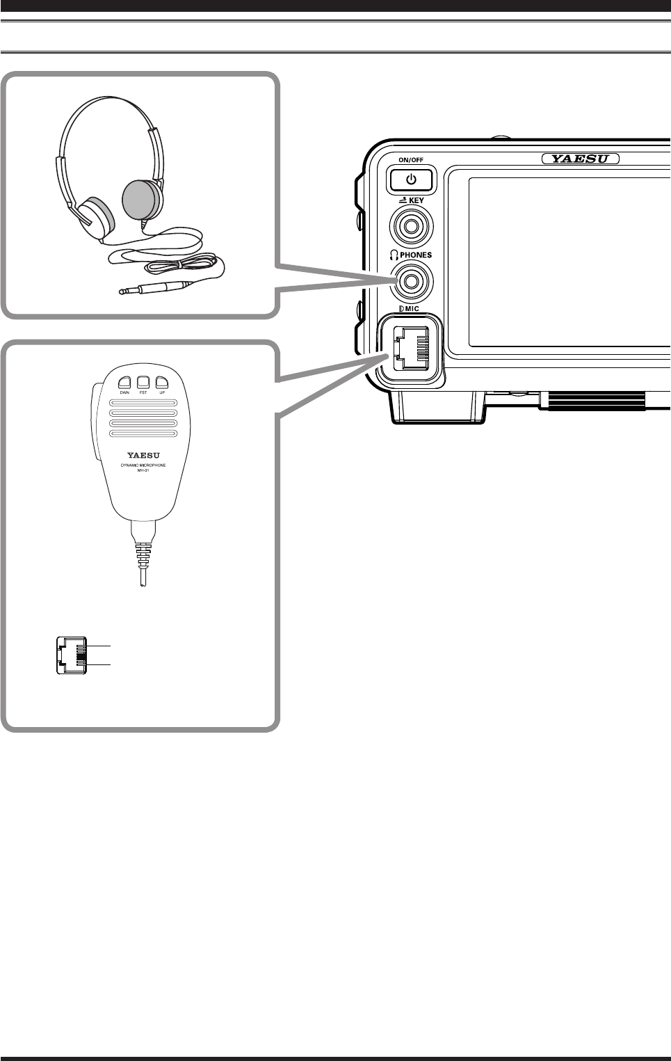
connection oF Microphone And heAdphone
DOWN
UP
+5V
MIC GND
MIC
PTT
GND
FAST
Page 10 FT-991 OperaTing Manual
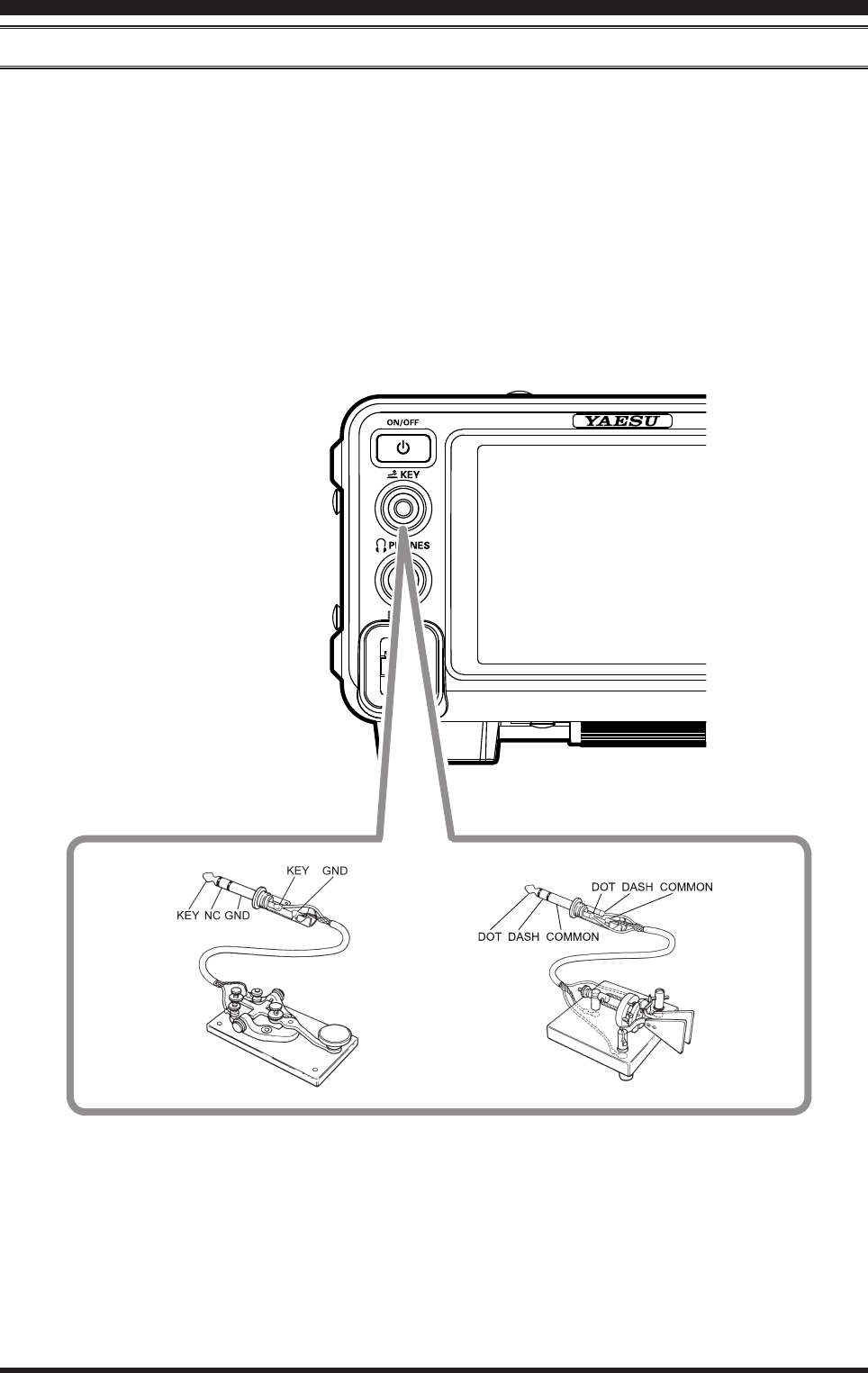
key, keyer, And coMputer-driven keying interconnectionS
The FT-991 includes many features for the CW operator. These functions will be detailed in the “Operation” section
later. Besides the built-in Electronic Keyer, two key jacks are provided, one on the front and one on the rear panel, for
convenient connection to keying devices.
The Menu selections allow you to congure the front panel KEY jack according to the device you wish to connect. For
example, you may connect your keyer paddle to the front panel KEY jack, and use Menu item “018 F KEYER TYPE” for
paddle input.
The KEY jack on the FT-991 utilize “Positive” keying voltage. Key-up voltage is approximately +3.3V DC, and key-
down current is approximately 4 mA. When connecting a key or other device to the KEY jack, use only a 3-contact
(“stereo”) 1/4” phone plug; a 2-contact plug will place a short between the ring and (grounded) shaft of the plug, result-
ing in a constant “key-down” condition in some circumstances.
insTallaTion and inTerConneCTions
Page 11
FT-991 OperaTing Manual
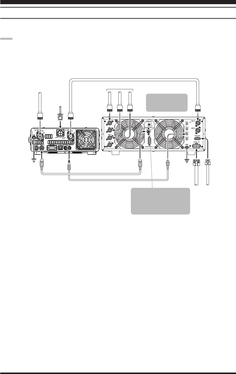
DC 13.8 V
CT-58 ALC Cable (Option)
CT-58 Band Data Cable (Option)
144/430MHz Antenna HF/50MHz Antenna
Coaxial Cable (50Ω)
Connect to “INPUT 1” of the VL-1000
INPUT
BAND-DATA 1
ALC 1
TUN/LIN
REM/ALC
GND
GND
VP-1000
VP-1000 CONTROL
DC 48V IN
ANT 1
ANT 2
ANT 3
INPUT 1
ANT
144/430MHz
ANT
HF/50MHz
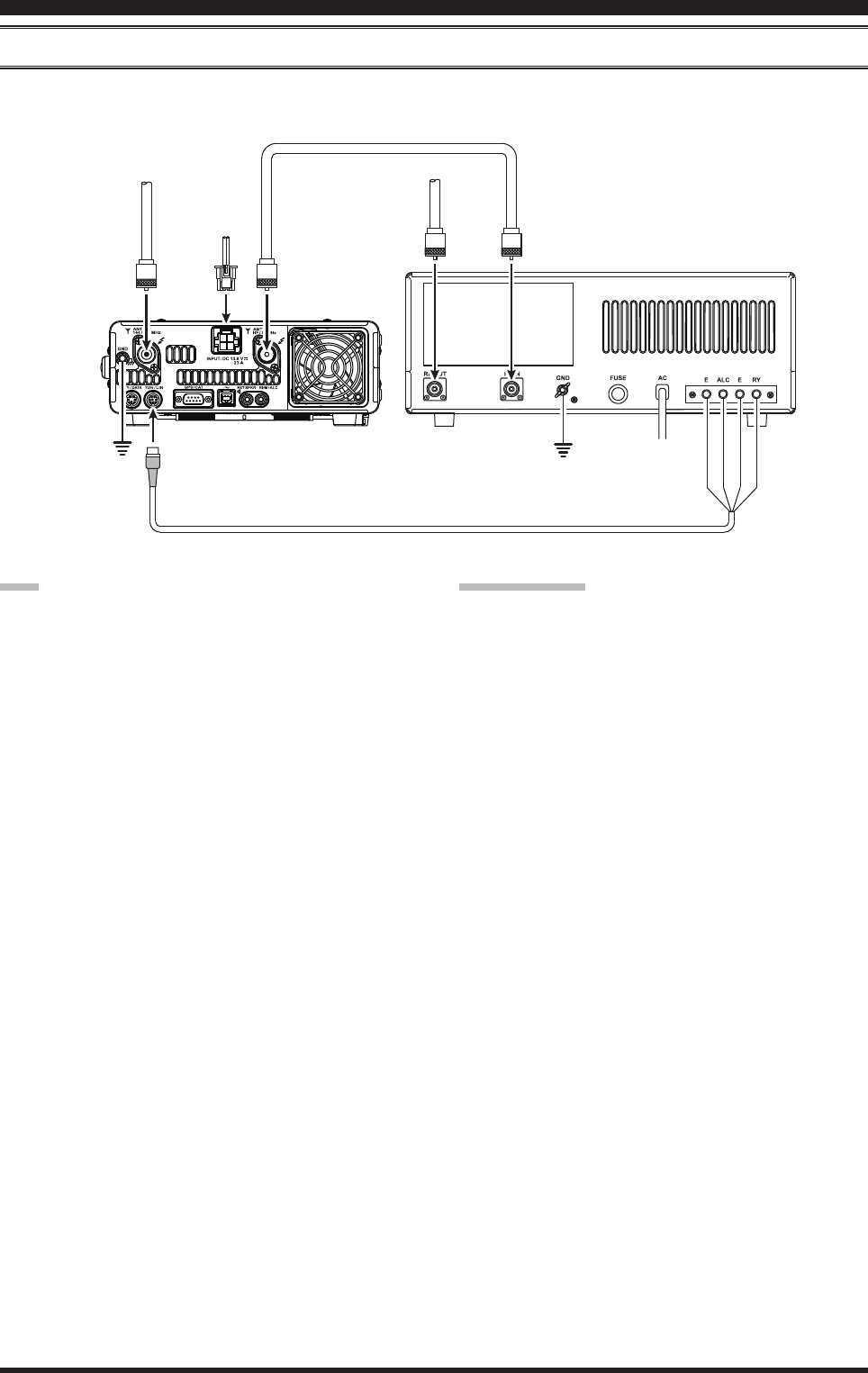
insTallaTion and inTerConneCTions
vl-1000 lineAr AMpliFier interconnectionS
Be sure that both the FT-991 and VL-1000 are turned off, and then follow the installation recommendations contained
in the illustration.
note:
Refer to the VL-1000 Operating Manual for details regarding amplier operation.
Do not attempt to connect or disconnect coaxial cables when your hands are wet.
To link the FT-991 and VL-
1000 Power switches, set the
VL-1000 REMOTE switch to
the “ON” position.
Set the front panel’s
INPUT switch to the
“INPUT1”.
Page 12 FT-991 OperaTing Manual
insTallaTion and inTerConneCTions
interFAcing to other lineAr AMpliFierS
note
The TX GND OUT pin (pin 2) of the TUN/LIN jack
is a transistor “open collector” circuit. It is capable of
handling positive relay coil voltages up to +60VDC
at 200 mA or +30 VDC at 1 A. If you plan to use
multiple linear amplifiers for different bands, you
must provide external band switching of the “Linear
Tx” relay control line from the “TX GND OUT” line
at the TUN/LIN jack.
The specied range for ALC voltage to be used with
the FT-991 is 0 to -4 Volts DC.
Amplier systems utilizing different ALC voltages
will not work correctly with the FT-991, and their
ALC lines must not be connected if this is the case.
iMportAnt note!
Do not exceed the maximum voltage or current rat-
ings for the “TX GND OUT” pin (pin 2) of the TUN/
LIN jack. This line is not compatible with negative
DC voltages, or AC voltages of any magnitude.
Most amplifier control relay systems require only
low DC voltage/current switching capability (typi-
cally, +12V DC at 25 ~ 75 mA), and the switching
transistor in the FT-991 will easily accommodate
such ampliers.
DC 13.8 V
Linear Amplifier Connection Cable
(Option: T9207451)
144/430MHz Antenna HF/50MHz Antenna
Coaxial Cable (50Ω)
Connect to “INPUT” of the linear amplifier
INPUT
TUN/LIN
GND
GND
GND
TX GND
EXT ALC
GND
INPUT
ANT
ANT
144/430MHz
ANT
HF/50MHz
Page 13
FT-991 OperaTing Manual
ON/OFF Switch
Press and hold in this switch for one second to turn
the transceiver on. Similarly, press and hold in this
switch for one second to turn the transceiver off.
KEY Jack
This 1/4-inch, 3-contact jack accepts a CW key or
keyer paddles (for the built-in electronic keyer), or
output from an external electronic keyer. Pinout is
shown on page ##. Key up voltage is +3.3 V DC,
and key down current is 4 mA. This jack may be
configured for keyer, “Bug”, “straight key”, or
computer keying interface operation via Menu item
“011 F CW KEYER” (see page ##).
note:
You cannot use a 2-contact plug in this jack (to do so
produces a constant “key down” condition).
PHONES Jack
A 1/4-inch, 3-contact jack accepts either monaural or
stereo headphones with 2- or 3-contact plugs. When
a plug is inserted, the loudspeaker is disabled.
note:
When wearing headphones, we recommend that you
turn the AF Gain levels down to their lowest settings
before turning power on, to minimize the impact on
your hearing caused by audio “pops” during switch-
on.
MIC Jack
This 8-pin jack accepts input from a microphone uti-
lizing a traditional YAESU HF transceiver pinout.
fronT panel ConTrols & swiTChes
4
3
2
1
5
789
6

Page 14 FT-991 OperaTing Manual
fronT panel ConTrols & swiTChes
F(M-LIST) Button
F
This button is used to display function list. The fol-
lowing functions can be accessed from the function
list:
NAR/WIDE, NB, AGC, ATT, IPO, NOTCH, CONT,
DNR, DNF, SHIFT, WIDTH, MOX, VOX, MONI,
MIC-EQ, PROC, BK-IN, SPEED, SQL
M-LIST
Pressing and holding this button will show the mem-
ory channel list. ........
MENU(SETUP) Button
MENU
This button is used to access the Menu system. The
various transceiver characteristics may be config-
ured.
SETUP
Pressing and holding this button will .......
BAND Button
These keys allow one-touch selection of the desired
Amateur band (1.8 ~ 50 MHz).
The keys may also be used for direct entry of a de-
sired operating frequency during VFO operation.
MODE Button
This button selects the operating mode. The selec-
tions available are:
LSB, USB, AM, CW (LSB), CW (USB), FM,
RTTY (LSB), RTTY (USB), C4FM, DATA (LSB),
DATA (USB), DATA (FM)
MULTI Knob
This knob allows you to select the Menu items and
settings.
Page 15
FT-991 OperaTing Manual
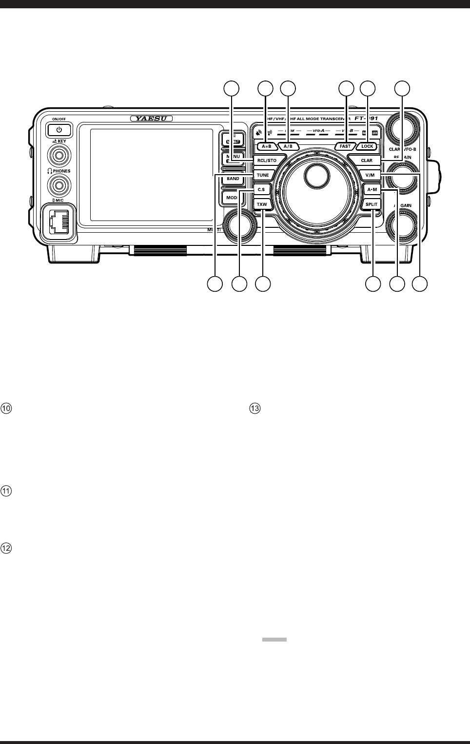
A=B Button
Press this button momentarily to transfer the fre-
quency or memory channel data, from VFO-A to
VFO-B, overwriting any previous contents in VFO-
B. Use this key to set both VFO-A and VFO-B to the
same frequency and mode.
A/B Button
Pressing this button momentarily, exchanges the
frequency or memory channel data, of VFO-A and
VFO-B.
RCL/STO Button
RCL (Recall)
Pressing this button, recalls one of up to ve Quick
Memory Bank memories for operation.
STO (Store)
Pressing this button copies the contents (frequency,
mode, bandwidth, FM repeater offset, and CTCSS
settings) of VFO-A, into consecutive QMB Memo-
ries.
TUNE Button
This is the on/off switch for the FT-991’s Automatic
Antenna Tuner.
Pressing this button momentarily places the antenna
tuner in line between the transmitter nal amplier
and the antenna jack (The “TUNER” icon will ap-
pear in the display). Reception is not affected.
Pressing and holding in this button for two seconds,
while receiving in an amateur band, activates the
transmitter for a few seconds while the automatic
antenna tuner rematches the antenna system imped-
ance for minimum SWR. The resulting setting is au-
tomatically stored in one of the antenna tuner’s 100
memories for instant automatic recall later when the
receiver is tuned near the same frequency.
Pressing this button momentarily, while the Tuner is
engaged, will take the Automatic Antenna tuner out
of the transmit line.
note:
When the Automatic Antenna Tuner is tuning itself,
a signal is being transmitted. Therefore, be certain
that an antenna or dummy load is connected to the
selected antenna jack before pressing and holding in
the TUNE button to start antenna tuning.
fronT panel ConTrols & swiTChes
13 14 15 19
20
10 11 16 1712 18
21

Page 16 FT-991 OperaTing Manual
fronT panel ConTrols & swiTChes
C.S Button
Press this button momentarily to directly recall a fa-
vorite Menu Selection.
To program a Menu selection to the C.S button,
press the MENU(SETUP) button to enter the
Menu. Select the Menu item you want to set as
the short cut. Press the C.S button, then press the
MENU(SETUP) button; this will lock in the select-
ed Menu item as the short cut.
TXW (TX Watch) Button
Pressing and holding this button lets you monitor the
transmit frequency when split frequency operation is
engaged. Release the button to return to normal split
frequency operation.
FAST Button
Pressing this button will change the tuning of the
Main Tuning Dial knob (VFO-A) to a higher step
rate.
When this function is activated, the “FAST” indica-
tor in the LED indicators area illuminates.
LOCK Button
This button toggles locking on/off for the Main Tun-
ing Dial knob (VFO-A). With “Lock” on, the Main
Tuning Dial knob can still be turned, but the fre-
quency will not change, and the “LOCK” indicator
in the LED indicators area illuminates.
CLAR Button
RX
Pressing this button activates the RX Clarier. This
will allow you to temporarily adjust the receive
frequency up to ±9.999 kHz with the CLAR/VFO-
B knob. Press this button once more to return the
receiver to the original frequency; the Clarier offset
will be remembered, in case you want to use it again.
To cancel the Clarifier offset, press the [CLEAR]
button.
Pressing this switch during Split operation will
change the tuning rate of the CLAR/VFO-B knob
(VFO-B) to 100 Hz/step.
When this function is activated, the “FAST” indica-
tor in the LED indicators area illuminates.
TX
Pressing this button activates the TX Clarier, to al-
low offsetting the transmit frequency temporarily.
Press this button once more to return the transmit-
ter to the original frequency; the Clarifier offset
will be remembered, though, in case you want to
use it again. To cancel the Clarier offset, press the
[CLEAR] button.
V/M Button
This button toggles frequency control between VFO-
A and the memory system. In memory mode, “MEM”
(Memory Channel) will be shown in the display to
indicate the current selection. Pressing the V/M but-
ton displays the original memory frequency, and the
“MEM” will be displayed. Pressing it once more
returns frequency operation to VFO-A, and the icon
will no longer be displayed.
A
M Button
Pressing this button momentarily, displays the con-
tents of the currently-selected memory channel for
10 seconds.
Pressing and holding in this key for one second (until
the double beep) copies the current operating data
into the currently selected memory channel, over-
writing any previous data stored there.
SPLIT Button
Press this button to operate split frequency between
VFO-A (used for reception) and VFO-B (used for
transmission). If you press and hold in the SPLIT
button for one second, the “Quick Split” feature will
be engaged. VFO-B transmit will automatically be
set to a frequency 5 kHz higher than the VFO-A re-
ceive frequency, with the same operating mode. The
transceiver will operate in the Split mode.
Page 17
FT-991 OperaTing Manual
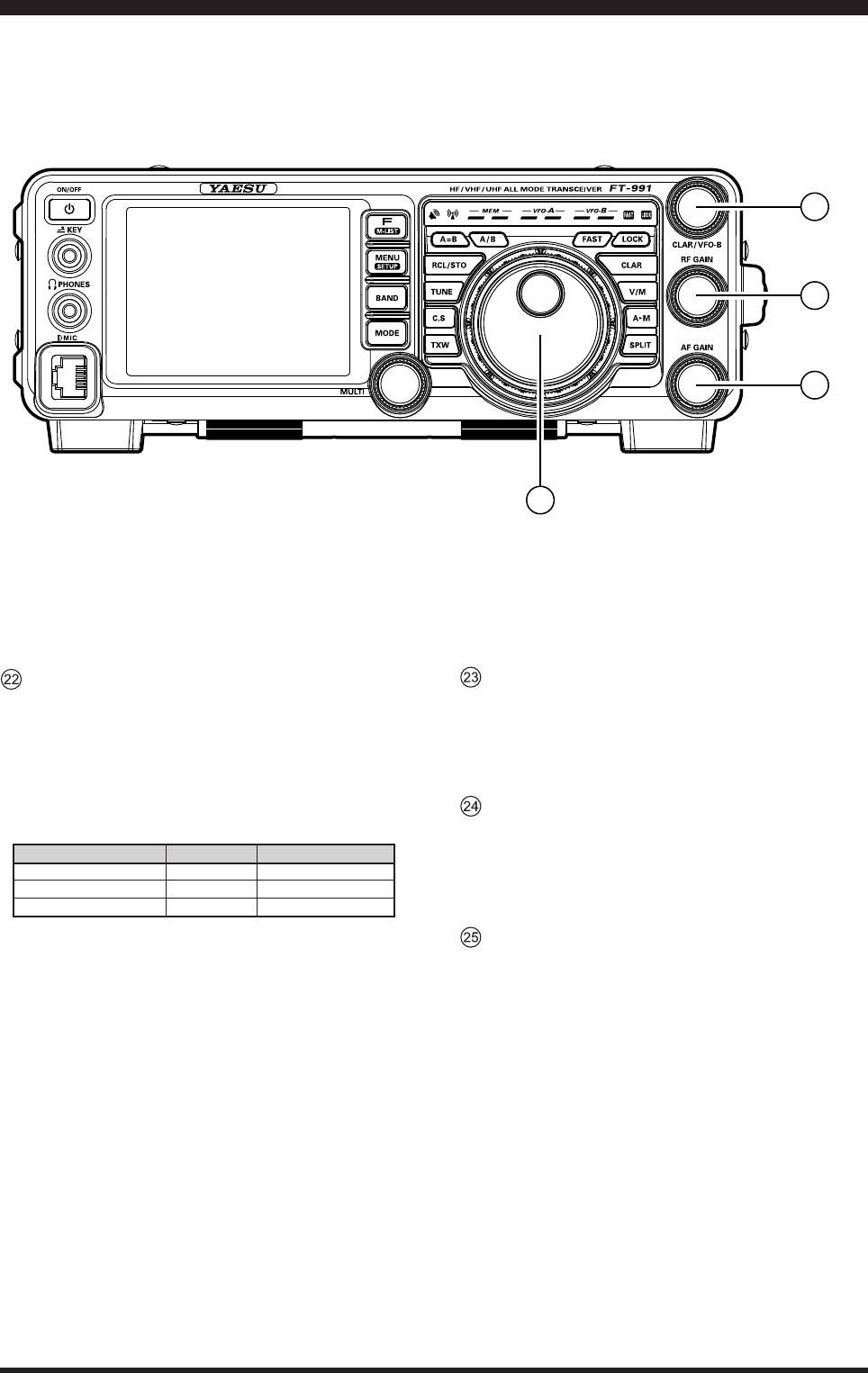
Main Tuning Dial Knob
This large knob adjusts the operating frequency of
VFO-A. Clockwise rotation of this knob increases
the frequency. Default tuning increments are 10 Hz
(CW, SSB), 50 Hz (RTTY/DATA), 100 Hz (AM/
FM). When the FAST button is pressed, the tuning
steps increases. The available steps are:
operAting Mode
LSB/USB/CW
AM/FM
RTTY/DATA
1 Step
10 Hz (100 Hz)
100 Hz (1 kHz)
5 Hz (100 Hz)
1 diAl rotAtion
10 kHz (100 kHz)
100 kHz (1 MHz)
5 kHz (100 kHz)
Numbers in parentheses indicate steps when the FAST button is On.
fronT panel ConTrols & swiTChes
CLAR/VFO-B Knob
During the VFO-A operation, this knob tunes the
Clarier offset frequency up to ±9.999 kHz.
During Split operation, this knob adjusts the operat-
ing frequency of VFO-B.
RF GAIN Knob
The
RF GAIN knob is the receiver RF gain control,
which adjusts the gain of the receiver RF and IF
amplier stages. This control is normally left in the
fully clockwise position.
AF GAIN Knob
The
AF GAIN knob sets the receiver audio volume
level. Typically, you will operate with this control set
between the 9 o’clock and 10 o’clock positions.
23
24
25
22
Page 18 FT-991 OperaTing Manual
displaY indiCaTions
Mode Indicator
Displays the current operating mode.
VFO-A Frequency Display
Shows the main band (VFO-A) frequency.
Tuning Offset Indicator
This indicates the relative offset of the CW-TUNE,
μ-TUNE, Clarier, etc.
CongurationIndicator
TUNER
This indicator appears when the internal Automatic
Antenna Tuner is activated.
VOX
This indicator appears when the automatic voice-
actuated transmitter switches in the SSB, AM, and
FM modes.
PROC
This indicator appears whenever the DSP Speech
Processor is activated.
MIC EQ
This indicator appears whenever the Three-Band
Parametric Microphone Equalizer is activated via
the Menu.
NAR
This indicator appears whenever the receiver’s
narrow IF DSP lter is engaged.
REC
This indicator appears while the optional Voice
Memory Unit is recording your voice message, or
the Contest Keyer is recording your CW keying.
PLAY
This indicator appears while the optional Voice
Memory Unit is playing back the recorded voice
message, or the recorded Contest CW keying.
[+]/[-]
During FM repeater operation, a negative frequen-
cy shift will be indicated by “[-]” while a positive
frequency shift will be indicated by “[+]”.
DNR
This indicator appears whenever the Digital Noise
Reduction feature is activated.
DNF
This indicator appears whenever the Digital Notch
Filter is activated.
LCD Display

Page 19
FT-991 OperaTing Manual
VFO-B Frequency Display
Shows the sub band (VFO-B) frequency during Split
operation.
S/PO Meter
On reception, this indicates the received signal
strength from S-0 to S-9+60dB.
On transmission, this indicates the RF Power Output,
from 0 to 150 Watts.
Advice:
The S/PO meters can be set to the Peak-hold
function (BAR type only) via the menu item “008
BAR MTR PEAK HOLD”.
Scope Display
Function Keys
Clock
Indicates the current time.
displaY indiCaTions
Page 20 FT-991 OperaTing Manual
displaY indiCaTions
LED Indicators
RX Indicator
This indicator illuminates when the squelch opens.
TX Indicator
This indicator illuminates during transmission.
Memory Mode RX/TX Indicators
Green (Left):
This indicator illuminates when the receiver is ac-
tive on the memory channel.
Red (Right):
This indicator illuminates when the transmitter is
active on the memory channel.
Main Band RX/TX Indicators
Green (Left):
This indicator illuminates when the receiver is ac-
tive on the main band (VFO-A).
Red (Right):
This indicator illuminates when the transmitter is
active on the main band (VFO-A).
Sub Band RX/TX Indicators
Green (Left):
This indicator illuminates when the receiver is ac-
tive on the main band (VFO-B).
Red (Right):
This indicator illuminates when the transmitter is
active on the main band (VFO-B).
FAST/LOCK Indicators
FAST:
This indicator appears when the Main Tuning Dial
knob tuning rate is set to “fast”.
LOCK:
This indicator appears when the Main Tuning Dial
knob is locked.
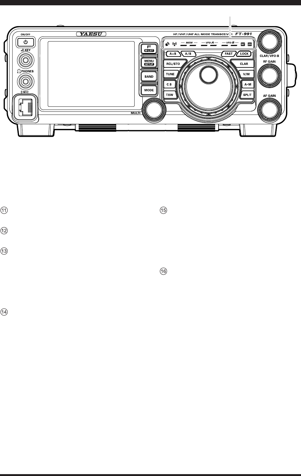
Page 21
FT-991 OperaTing Manual
6
45
3
1
12
7
8
rear panel
ANT Jack
Connect your main antenna(s) here, using type-M
(PL-259) connectors and coaxial feed lines. The in-
ternal antenna tuner affects only the antenna(s) con-
nected here, and only during transmission.
Warning!
The 100V RF voltage (@100 W/50 Ω) is applied to
the TX RF section of the transceiver while trans-
mitting. Do not touch the TX RF section while
transmitting.
DC IN Jack
This is the DC power supply connection for the
transceiver. Use the supplied DC cable to connect di-
rectly to a DC power supply, which must be capable
of supplying at least 23 A @13.8 VDC.
GND
Use this terminal to connect the transceiver to a good
earth ground, for safety and optimum performance.
Use a large diameter, short braided cable for making
ground connections, and please refer to page ## for
other notes about proper grounding.
To prevent damage from lightning, atmo-
spheric electricity, electrical shock, etc., be
certain to provide a good earth ground.
TUN/LIN Jack
TUN (Tuner)
This 8-pin output jack is used for connection to the
FC-40 External Automatic Antenna Tuner.
LIN (Linear)
This 8-pin output jack provides band selection data,
which may be used for control of optional accesso-
ries such as the VL-1000 Solid-state Linear Ampli-
er.
RTTY/DATA Jack
This 6-pin input/output jack accepts AFSK input
from a Terminal Node Controller (TNC) or an op-
tional interface unit; it also provides xed level (100-
mV @600 Ohms) receiver audio output, and FSK
keying line.
REM/ALC Jack
REM (Remote)
By plugging the optional FH-2 Remote Control
Keypad into this gold-plated jack, direct access to
the FT-991 CPU is provided for control functions
such as contest memory keying, plus frequency and
function control.
ALC ( )

Page 22 FT-991 OperaTing Manual
rear panel
EXT SPKR Jack
This 3.5-mm, 2-contact, gold-plated jack provides
variable audio output for an external loudspeaker.
The audio output impedance at this jack is 4 - 8
Ohms, and the level varies according to the setting of
the front panel AF GAIN knob. Inserting a plug into
this jack disables the internal loudspeaker.
GPS/CAT Jack
This 9-pin serial DB-9 jack allows external computer
control of the FT-991. Connect a serial cable here
and to the RS-232C COM port on your personal
computer (no external interface is required).
Page 23
FT-991 OperaTing Manual
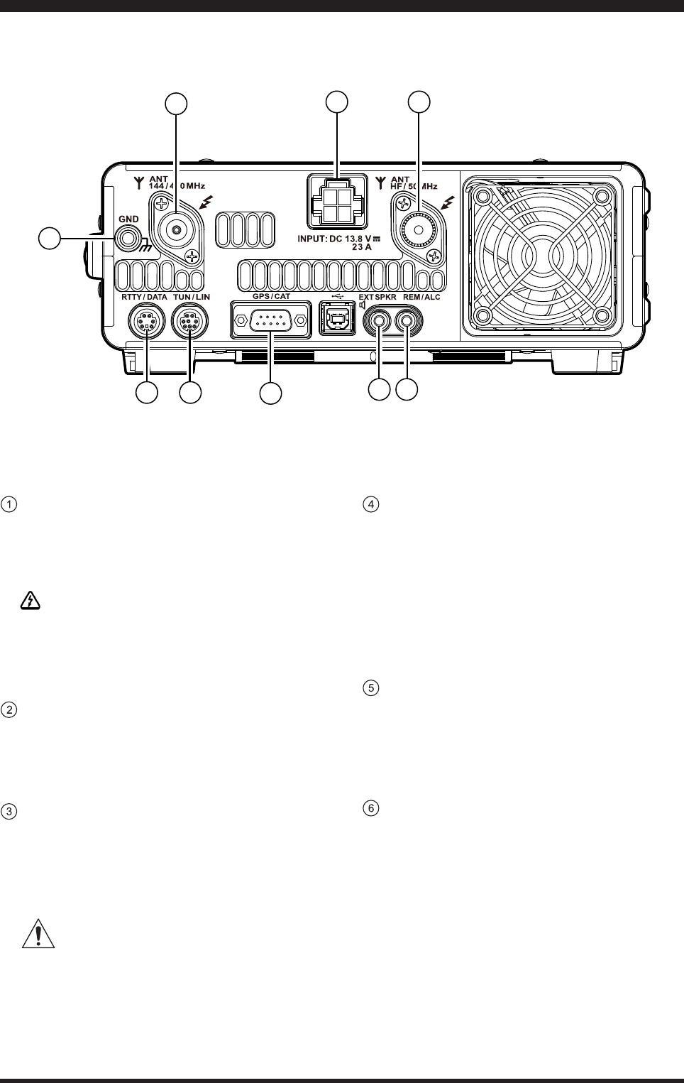
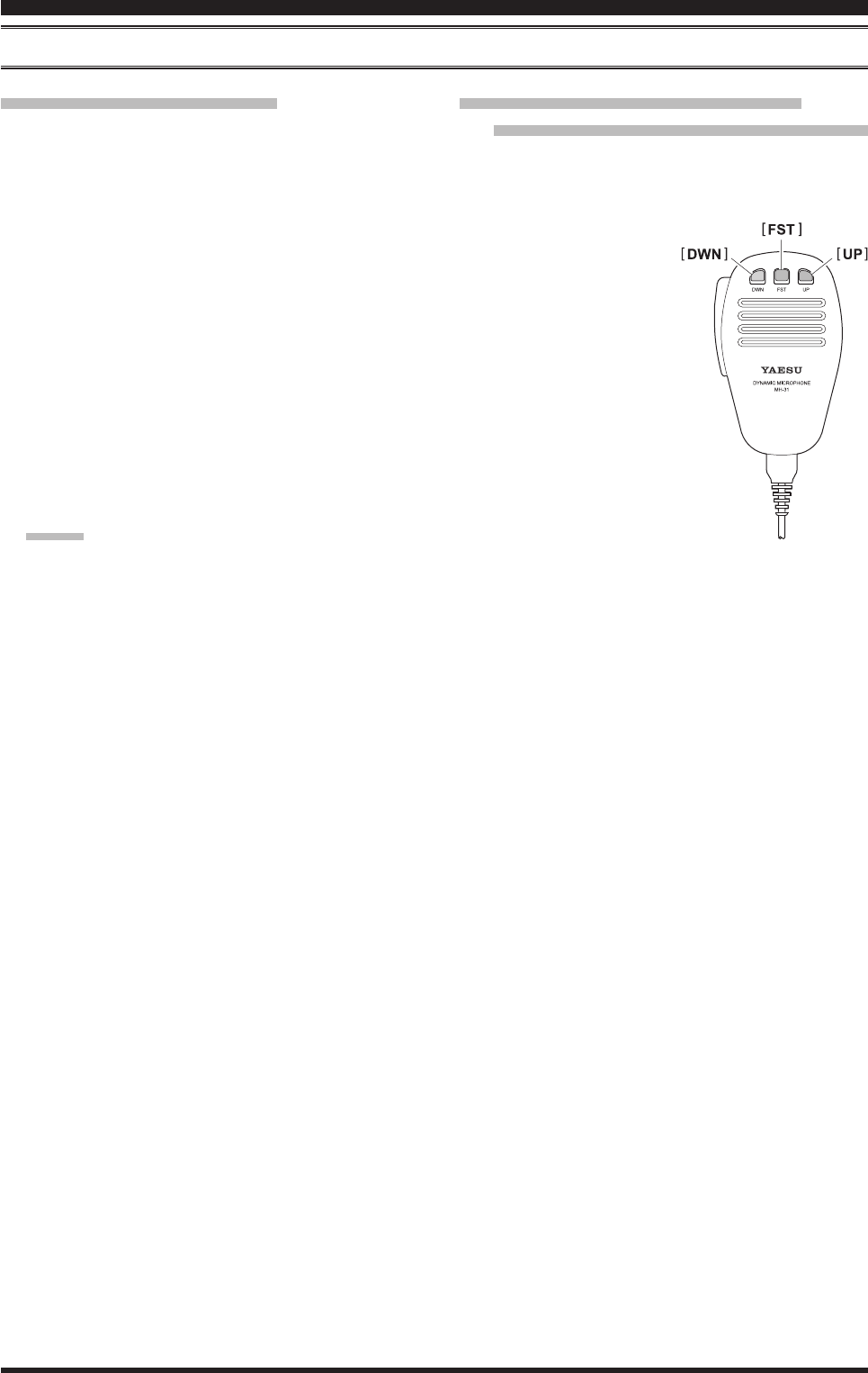
Mh-31a8J MiCrophone swiTChes
43
21 5 PTT Switch
Press and hold the PTT (Push To Talk) switch to
start transmission.
DWN Button
Press the DWN (Down) button to scan the frequency
downward.
FST Button
Press the FST (Fast) button to increase the tuning
rate by a factor of ten when scanning the frequency.
UP Button
Press the UP button to scan the frequency upward.
Microphone
Speak into here during transmission.
Page 24 FT-991 OperaTing Manual
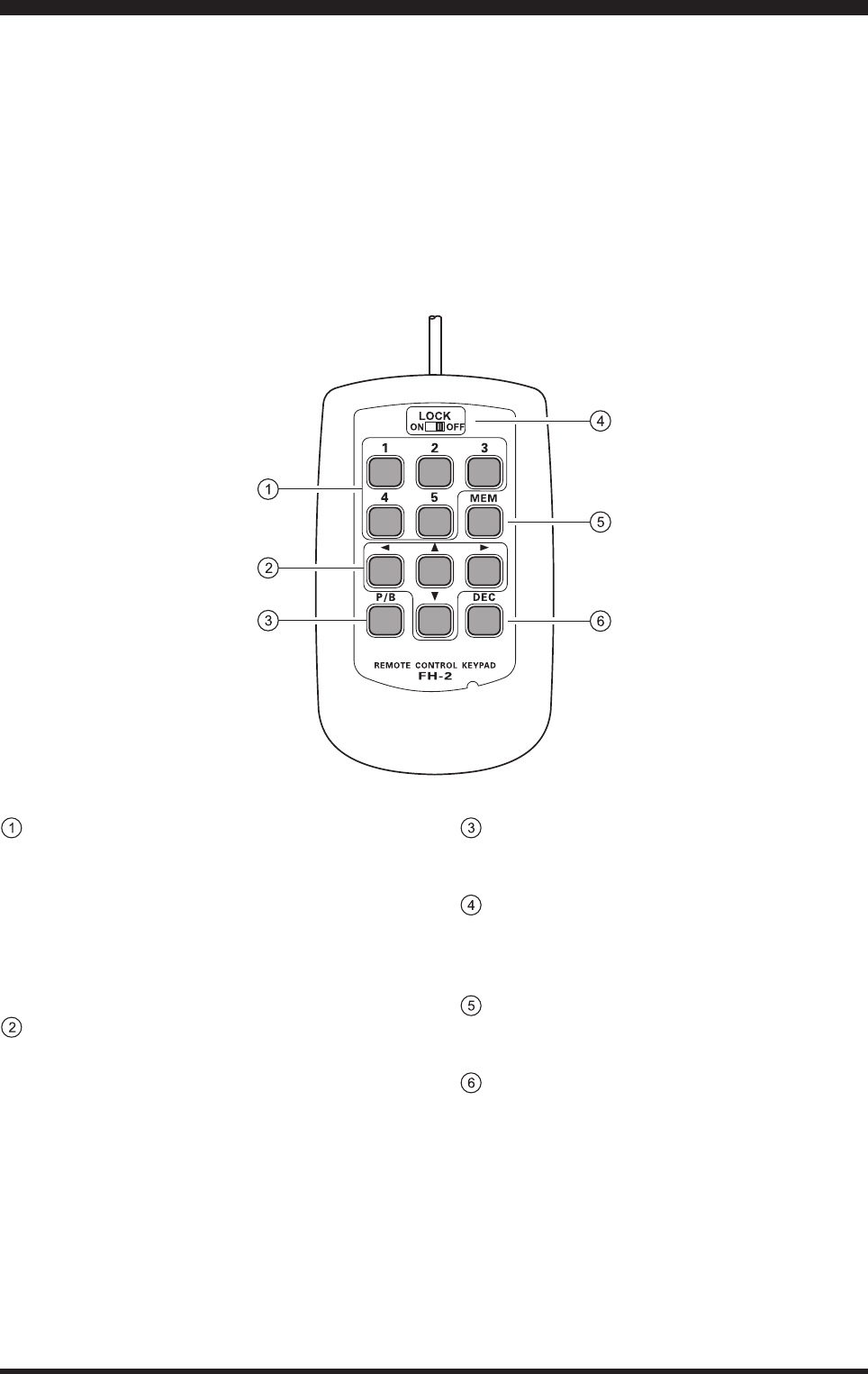
opTional fh-2 swiTChes
The optional Remote Control Keypad FH-2 can be used to control the optional DVS-6 Voice Memory capability for the
SSB/AM/FM modes; the contest memory keyer for the CW mode; and the text memory for the RTTY/DATA modes.
Some specic capabilities of the FH-2 are:
m On SSB/AM/FM modes, ve channels of storage and playback of voice memory (20 seconds each), using your own
voice for recording (see page 71).
m On CW mode, the FH-2 provides storage and recall of CW messages for repetitive CQ and contest automatic number
transmissions (see page 85).
m On RTTY/DATA mode, the FH-2 provides storage and recall of TEXT messages for repetitive CQ transmissions (see
pages 104, 106).
[1], [2], [3], [4], [5] Buttons
These buttons work as the Voice Memory and CW
Message Memory Selection Key.
In the case of Voice Memory, up to 20 seconds of
audio may be stored on each channel.
For CW Messages and CW Text Messages, up to 50
characters ("PARIS" specification) may be stored
into each channel.
[t], [], [p], [q] Buttons
Usually, these buttons are used for tuning the VFO
frequency. Press the [p]/[q] buttons to change the
frequency in the same increments as the microphone
[UP]/[DWN] switches. Press the [t]/[] buttons to
change the frequency by 100 kHz steps.
When programming the Contest Memory Keyer,
these buttons are used to move the cursor and select
the text characters.
[P/B] Button
This button can be used to insert a space into the
position where the cursor is blinking.
[LOCK] Button
This button may be used to lock out the FH-2 key
buttons, to prevent accidental activation of FH-2
operations.
[MEM] Button
Press this button to store either a Voice Memory, or a
Contest Keyer Memory.
[DEC] Button
When utilizing the sequential contest number
capability of the Contest Keyer, press this button to
decrement (decrease) the current Contest Number by
one digit (i.e. to back up from #198 to #197, etc.).

Page 25FT-991 OperaTing Manual
Before turning on the main power, please verify the following items once more.
Have you made all ground connections securely? See page ## for details.
Do you have your antenna(s) connected to the rear-panel Antenna jack(s)? See page ## for details.
Is your microphone (and/or key or paddle) connected? See pages ##, ## for details.
If using a linear amplier, have all interconnections been successfully completed? See pages ##, ## for details.
Please rotate the AF GAIN control to the fully counter-clockwise position, to avoid a loud blast of audio when the
transceiver turns on. See page ## for details.
basiC operaTion: reCeiving on aMaTeur bands
Page 26 FT-991 OperaTing Manual
Amateur band key may similarly have up to three
frequency/mode settings applied.
When [MHz] is touched, the “MHz” notation
will appear in the display, and then rotation of the
CLAR/VFO-B knob will change the frequency
in 1 MHz steps.
6. Press the MODE button to display the available se-
lections.
Touch the corresponding key to select the desired
operating mode.
Advice:
By convention in the Amateur bands, LSB is
used on the 7 MHz and lower bands (with the
exception of 60 meters), while USB is utilized on
the 14 MHz and higher bands.
When changing modes from SSB to CW, you
will observe a frequency shift on the display.
This shift represents the BFO offset between the
“zero beat” frequency and the audible CW pitch
(tone) you can hear (the pitch is programmed via
the Menu item “060 CW FREQ DISPLAY”), even
though the actual tone that you hear is not chang-
ing.
When operating on the FM mode, repeatedly
touch [SQL] (Squelch) on the screen displayed
by pressing the F(M-LIST) button to point where
the background noise is just silenced. This is the
point of maximum sensitivity to weak signals.
Excessive advancement of [SQL] will decrease
the ability of the receiver to detect weak signals.
1. Turn on the external DC power supply.
2. Press and hold in the front-panel ON/OFF switch
until the transceiver turns on. After about ve sec-
onds, the transceiver is ready for full operation.
3. The transceiver will start up on 7.000.00 MHz LSB,
(or the previously used operating frequency) and
normal operation may begin.
note:
To turn power off, press and hold in the front panel
ON/OFF switch for one second.
4. Rotate the AF GAIN knob to set a comfortable au-
dio level of the incoming signals or noise. Clockwise
rotation of the AF GAIN knob increases the volume
level.
note:
When using headphones, start by rotating the AF
GAIN knob counter-clockwise, then bring the vol-
ume level up after you put the headphones on. This
will minimize the chance of damage to your hearing
caused by an unexpectedly high audio level.
5. Press the BAND button to display the list of Amateur
bands on the LCD, then touch a key corresponding
to the band on which you wish to begin operation.
Advice:
One-touch selection of each Amateur band be-
tween 1.8 and 50 MHz, 144 MHz, and 430 MHz
is provided.
The
FT-991 utilizes a triple band-stack VFO
selection technique, which permits storing up to
three favorite frequencies and modes onto each
VFO band register. For example, you may store
one frequency each on 14 MHz CW, RTTY, and
USB, then recall these frequencies by successive,
momentary touches of the [14] on the screen
displayed by pressing the BAND button. Each
Here is the typical start-up procedure for normal operation:
ON/OFF Switch
AF GAIN KnobMain Tuning Dial Knob
BAND Button
basiC operaTion: reCeiving on aMaTeur bands
MODE Button

Page 27FT-991 OperaTing Manual
7. Rotate the Main Tuning Dial knob to tune around the
band, and begin normal operation.
Advice:
Clockwise rotation of the Main Tuning Dial knob
increases the operating frequency, one “step”
of the synthesizer at a time; similarly, counter-
clockwise rotation of the Main Tuning Dial knob
will decrease the frequency. Two settings, one
“normal” and one “fast”, are available for each
operating mode. Pressing the FAST button en-
gages the “Fast” tuning selection (see chart be-
low).
MAin tuning diAl knob tuning rAte
operAting
Mode
1 Step 1 diAl rotAtion
LSB/USB/CW/
RTTY/DATA
1 / 5 / 10 Hz
(100 Hz)
1 / 5 / 10 kHz
(100 kHz)
AM/FM
100 Hz (1 kHz)
100 kHz (1 MHz)
Numbers in parentheses indicate steps when the FAST button is On.
If you want to effect rapid frequency change,
there are several techniques available:
Direct keyboard entry of the frequency.
Use the microphone’s UP/DWN scanning
keys, if your microphone is so equipped.
basiC operaTion: reCeiving on aMaTeur bands
Page 28 FT-991 OperaTing Manual
operAtion on 60-Meter (5 Mhz) bAnd (u.S. verSion only)
The recently-released 60-meter band is covered, in the FT-991, by xed memory channels. These channels are set to
USB or CW, and they appear between the “last” PMS channel (“P9U”) and the rst “regular” memory channel (Channel
1):
1. Press the V/M button once to enter the “Memory”
mode; the “MEM” icon will appear in the display.
2. Touch
[MCH] on the screen displayed by pressing
the F(M-LIST) button. The “MCH” notation and a
memory channel number will appear on the display
to signify that rotation of the MULTI knob will allow
selection of the memory channel.
3. Memory channels (“501” through “510”) are pre-
programmed, at the factory, with the permitted fre-
quencies in the 5 MHz band, and the USB or CW
mode is automatically selected on these channels.
4. To exit from 60-meter operation and return to the
VFO mode, just press the V/M button.
note:
The frequencies and operating mode for 5 MHz band
operation are xed, and may not be changed.
basiC operaTion: reCeiving on aMaTeur bands
V/M ButtonF(M-LIST) Button
MULTI Knob
Main Tuning Dial Knob
chAnnel
nuMber
501
502
503
504
505
506
507
508
509
510
5.332000 MHz
5.348000 MHz
5.358500 MHz
5.373000 MHz
5.405000 MHz
5.332000 MHz
5.348000 MHz
5.358500 MHz
5.373000 MHz
5.405000 MHz
Frequency
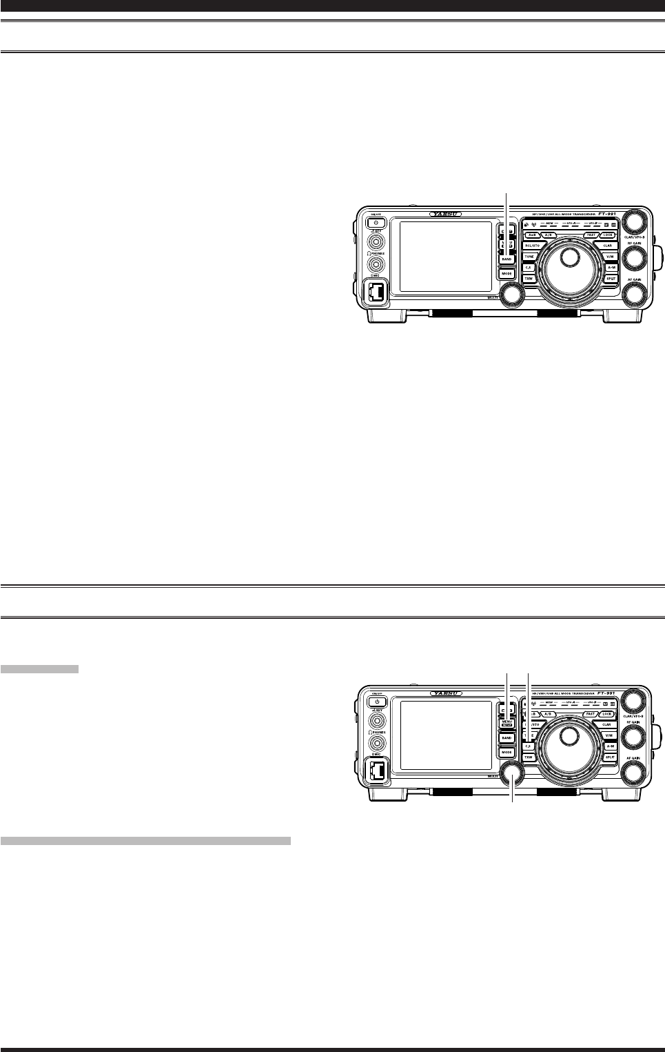
Page 29FT-991 OperaTing Manual
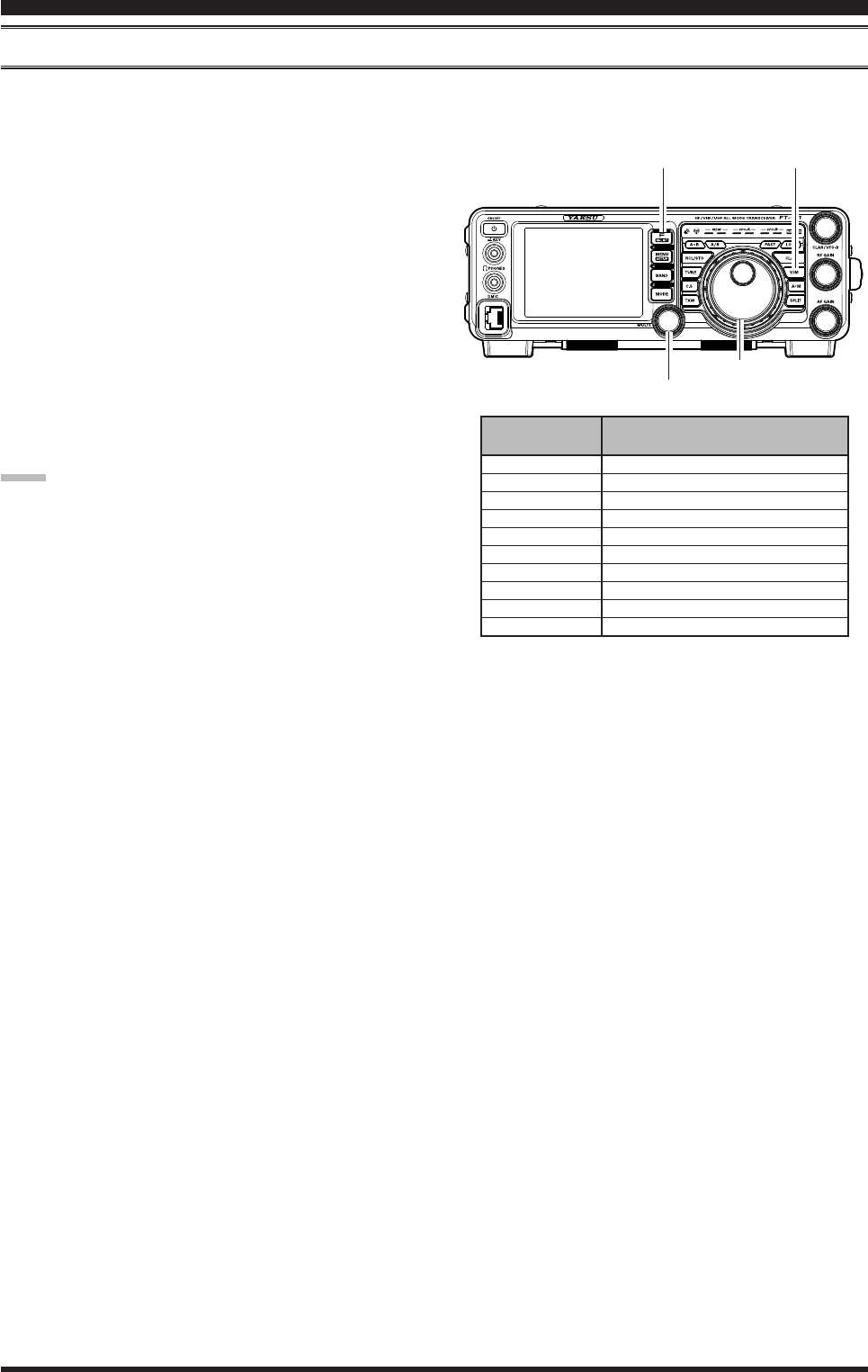
basiC operaTion: reCeiving on aMaTeur bands
clAr (clAriFier) operAtion
The CLAR button and CLAR/VFO-B knob are used to offset the receive frequency, the transmit frequency, or both,
from their settings on the VFO-A frequency. Four small numbers on the TFT Display show the current Clarier offset.
The Clarier controls on the FT-991 are designed to allow you to preset an offset (up to ±9.99 kHz) without actually re-
tuning, and then to activate it via the Clarier CLAR button. This feature is ideal for following a drifting station, or for
setting the small frequency offsets sometimes utilized in DX “Split” work.
Here is the technique for utilizing the Clarier:
1. Press the CLAR button. The “RX” notation will ap-
pear in the TFT Display, and the programmed offset
will be applied to the receive frequency.
2. Rotation of the CLAR/VFO-B knob will allow you
to modify your initial offset on the y. Offsets of up
to ±9.99 kHz may be set using the Clarier.
To cancel Clarier operation, press the CLAR button.
The “RX” notation will disappear from the display.
Advice:
Turning the Clarier off merely cancels the applica-
tion of the programmed offset from the receive and/
or the transmit frequencies. To clear the Clarier off-
set, and reset it to “zero,” press and hold the CLAR
button. The programmed offset is displayed in the
small multi-channel window of the frequency dis-
play.
The Clarier operation (including the offset frequen-
cy) will be memorized independently on each VFO
stack of VFO-A and VFO-B.
CLAR/VFO-B Knob
CLAR Button
Page 30
fT-991 operaTing Manual
MULTI Knob
MENU Button
Background color
basiC operaTion
:
reCeiving on aMaTeur bands
LOCK
You may lock the setting of the Main Tuning Dial knob (for VFO-A frequency tuning) and the CLAR/VFO-B knob (for
VFO-B frequency tuning during Split operation), to prevent accidental frequency change.
Main Tuning Dial Knob Lock
To lock the Main Tuning Dial knob, press the LOCK
button that is located to the right of the Main Tuning
Dial knob. To unlock the Dial setting, and restore nor-
mal tuning, press the LOCK button once more.
Advice:
The lock feature will be memorized independently on
the Main Tuning Dial knob and the CLAR/VFO-B
knob.
DIMMER
The illumination level of the TFT display and LED indicators (above the Main Tuning Dial knob), may be adjusted via
Menu items 009 and 010.
To adjust the illumination level:
1. Press the MENU button to enter the Menu mode.
2. Rotate the MULTI knob to select Menu item “006
DIMMER LED” (for LED indicators) or “007 DIM-
MER TFT” (for TFT display).
3. Touch
[SELECT] on the LCD then rotate the
MULTI knob to select the desired illumination level.
4. Touch
[ENTER] on the LCD, then touch [BACK]
on the LCD or press the MENU button to save the
new setting and exit to normal operation.
MULTI Knob
MENU Button
VFO COLOR
The background color of the VFO-A frequency in the TFT display may be selected via Menu item 007.
1. Press the MENU button to enter the Menu mode.
2. Rotate the MULTI knob to select Menu item “005
DISPLAY COLOR”.
3. Touch
[SELECT] on the LCD, then rotate the
MULTI knob to select from the following colors:
BLUE (default) / SKY BLUE / GREEN / PURPLE /
RED / ORANGE / GRAY
4. Touch
[ENTER] on the LCD, then touch [BACK]
on the LCD or press the MENU button to save the
new setting and exit to normal operation.
LOCK Button
Page 31FT-991 OperaTing Manual
ConvenienCe Features
Band Stack OperatiOn
The FT-991 utilizes a triple band-stack VFO selection technique, that permits you to store up to three favorite frequen-
cies and modes onto each band’s VFO register. For example, you may store one frequency each on 14 MHz CW, RTTY,
and USB, then recall these VFOs by successive, momentary touches of [14] on the screen displayed by the BAND but-
ton. Each Amateur band key may similarly have up to three frequency/mode settings applied. Note that only the VFO-A
system has the band stacks.
A typical setup, for the 14 MHz band, might be arranged like this:
1. Program 14.025 MHz, CW Mode, press the BAND
button, then touch [14] on the LCD;
2. Program 14.080 MHz, RTTY Mode, press the
BAND button, then touch [14] on the LCD;
3. Program 14.195 MHz, SSB Mode, press the BAND
button, then touch [14] on the LCD.
With this conguration, successive momentary touches
of [14] on the screen displayed by the BAND button
will allow you to step sequentially through these three
VFOs.
c.S (cuStOm Switch)
The front panel C.S button may be programmed to directly access an often-used Menu Mode selection.
BAND Button
C.S Setup
1. Press the MENU button to engage the Menu mode;
the Menu list will appear on the display.
2. Rotate the MULTI knob to select the Menu item you
want to access with the front panel C.S button.
3. Press the C.S button to lock in your selection.
4. Press the MENU button or touch [BACK] on the
LCD to save the new conguration and exit to nor-
mal operation.
Menu Selection Recall via C.S button
Press the C.S button.
The programmed Menu item will appear on the display.
Press the MENU button or touch [BACK] on the LCD
exit to normal operation.
MULTI Knob
C.S buttonMENU button
Page 32
fT-991 operaTing Manual
ConvenienCe feaTures
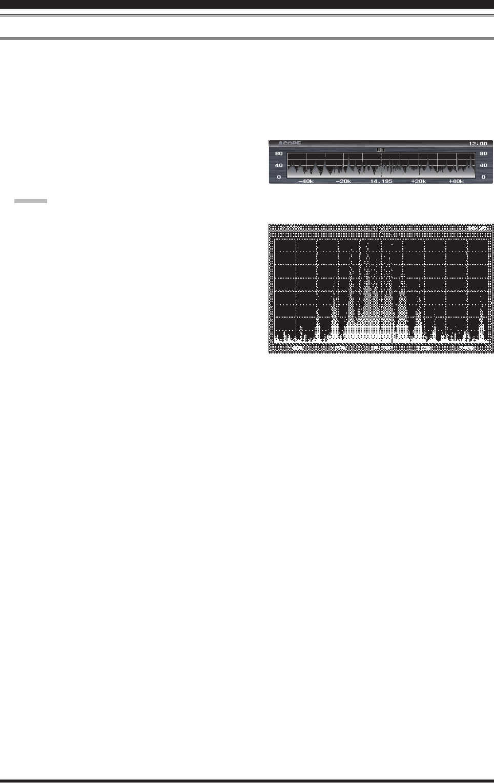
Scope
This function displays a convenient spectrum scope for monitoring the band conditions. Both strong and weak signals
can be displayed in an easy-to-understand manner on the TFT screen. This multifunctional scope takes into consid-
eration the operator’s preference, by switching between the convenient CENTER mode where the VFO frequency is
constantly in the center of the screen (for monitoring conditions on both sides of your operating frequency), and the FIX
mode, where the frequency is xed to the left side of the screen (for convenience in monitoring in the band).
Note: Since the FT-991 has only one receiver the audio will be muted while the spectrum scope is scanning.
1. Press the [SCOPE] button momentarily to display
the scope screen.
Five different screens are shown on the TFT display
by pressing the [SCOPE] button.
Advice:
During continuous sweeping, no audio will be heard.
Full screen spectrum scope display
SCOPE
Spectrum scope display
Page 33FT-991 OperaTing Manual
Using the UP/DWN buttons of the
supplied MH-31A8J Hand Microphone
The UP/DWN buttons on the supplied MH-31A8J Hand
Microphone may also be used to manually scan the fre-
quency upward or downward.
The microphone’s UP/
DWN buttons utilize the
tuning steps of the Main
Tuning Dial knob.
When the microphone FST
button is pressed, the tuning
rate increases by a factor of
ten, in a manner similar to
the transceiver front panel
FAST button.
Keyboard Frequency Entry
The Operating frequency may be entered directly into
the current VFO, using the keyboard screen displayed
by pressing the front panel BAND button.
Example: Enter 14.250.00 MHz
1. Press the BAND button to begin the direct frequency
entry process.
2. Touch
[ENT] on the LCD. The rst digit of the fre-
quency (the leftmost digit) will blink.
3. Enter, in order, the digits of the operating frequency,
touching the keys on the LCD
The decimal point after the “MHz” portion of the
frequency must be entered, but no decimal point is
required after the “kHz” portion.
3. Touch
[ENT] on the LCD once more to complete
the operating frequency entry. A short “beep” will
conrm that the entry was successful, and the new
operating frequency will appear on the display.
Advice:
If you attempt to enter a frequency outside the oper-
ating range of 30 kHz ~ 56 MHz, the microprocessor
will ignore the attempt, and you will be returned to
the previous operating frequency. If this happens,
please try again, taking care not to repeat the error in
the frequency entry process.
More Frequency nAvigAtion techniqueS
ConvenienCe feaTures
Page 34 FT-991 OperaTing Manual
ConvenienCe feaTures
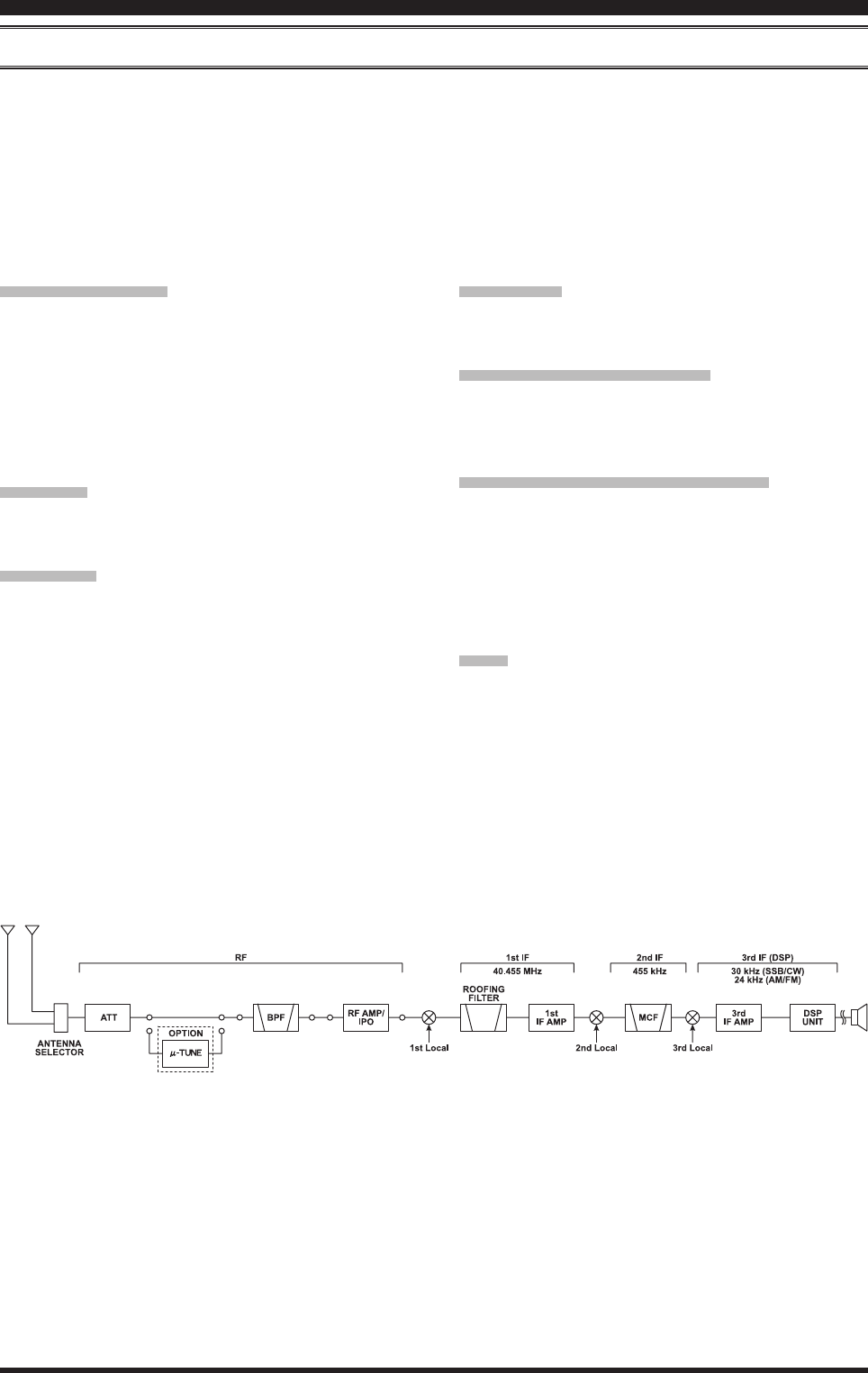
receiver operAtion (Front end block diAgrAM)
The FT-991 includes a wide range of special features to suppress the many types of interference that may be encoun-
tered on the HF bands. However, real world interference conditions are constantly changing, so optimum setting of the
controls is somewhat of an art, requiring familiarity with the types of interference and the subtle effects of some of the
controls. Therefore, the following information is provided as a general guideline for typical situations, and a starting
point for your own experimentation.
The FT-991 interference-ghting circuitry begins in its “RF” stages, and continues throughout the entire receiver sec-
tion. FT-991 allows conguration of the features described below.
CONTOUR Filter
The DSP Contour filter has the unique ability to pro-
vide either a null or a peak in tunable segments of the
receiver passband. You may suppress interference and
excessive frequency components on an incoming signal,
or you may peak those tunable frequency segments. The
level of the null or peak, and the bandwidth, over which
it is applied, are adjustable via the Menu.
IF SHIFT
The passband center frequency of the IF DSP lter may
be moved up or down by adjusting this control.
IF WIDTH
The width of the IF DSP ltering may be adjusted using
this control.
IF NOTCH
The IF Notch lter is a high-Q notch lter that can elim-
inate, or signicantly reduce an interfering carrier.
DNF (DigitalNotchlter)
When multiple interfering carriers are encountered dur-
ing reception, the Digital Notch Filter can signicantly
reduce the level of these signals.
DNR (Digital Noise Reduction)
The DSP’s Digital Noise Reduction (DNR) feature uti-
lizes 15 different mathematical algorithms to analyze
and suppress different noise proles encountered on the
HF/50 MHz bands. Choose the selection that provides
the best noise suppression, and allows the signal to rise
up out of the noise.
AGC
The AGC system is highly adaptable to changing signal
and fading characteristics, making reception possible
under the most difcult conditions.
Front end block diAgrAM
Page 35FT-991 OperaTing Manual
inTerferenCe reJeCTion
ATT (AttenuAtor)
When extremely strong local signals or high noise degrades reception, you can use [ATT] displayed by pressing the
F(M-LIST) button to insert 6, 12, or 18-dB of RF attenuation in front of the RF amplier.
1. Press the F(M-LIST) button, then touch [ATT] on
the LCD several times to set the desired attenuation
level, per the chart below.
OFF: Attenuator is Off
-6dB: The incoming signal power is reduced by 6
dB (Signal voltage reduced by 1/2)
-12dB: The incoming signal power is reduced by 12
dB (Signal voltage reduced to 1/4)
-18dB: The incoming signal power is reduced by 18
dB (Signal voltage reduced to 1/8)
The selected attenuation level will be indicated in
the ATT column of the Key Function Display on the
TFT display.
2. To restore full signal strength through the Attenuator
circuit area, touch [ATT] on the LCD to restore the
ATT display to the “OFF” position.
Advice:
If background noise causes a high S-meter indication on clear frequencies, touch [ATT] on the LCD until the S-
meter drops to about “S-1”. This setting optimizes the trade-off between sensitivity, noise, and interference immu-
nity. Also, once you have tuned in a station you want to work, you may want to reduce sensitivity further (add more
attenuation) by touching [ATT] on the LCD to a higher setting. This reduces the strength of all signals (and noise)
and can make reception more comfortable, important especially during long QSOs. When looking for weak signals
on a quiet band, you will want maximum sensitivity, so the IPO should be disabled and [ATT] on the LCD should be
set to “OFF.” This situation is typical during quiet times on frequencies above 21 MHz, and when using a small or
negative-gain receiving antenna on other bands.
F(M-LIST) Button
Page 36 FT-991 OperaTing Manual
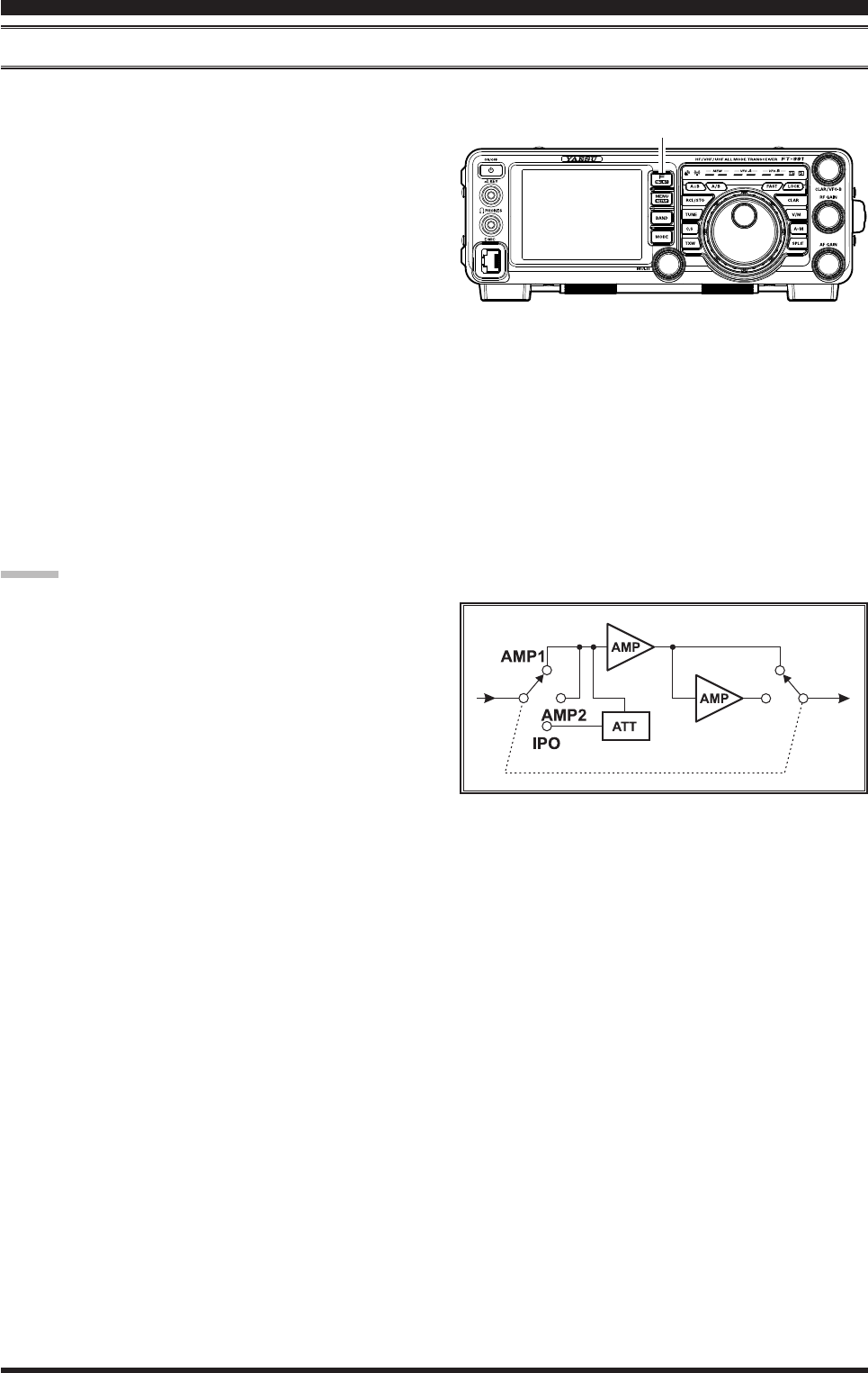
ipo (intercept point optiMizAtion)
The IPO feature allows the operator to optimize the characteristics of the receiver front end, depending on the current
noise level and the strength of incoming signals.
Touch [IPO] displayed by pressing the F(M-LIST) but-
ton repeatedly, to set the desired characteristic of the
receiver front end, according to the chart below.
AMP1: Amplies the incoming signals, using a low
distortion RF preamplier (gain: approx. 10
dB).
AMP2: Amplifies the incoming signals, using a
2-stage low-distortion RF preamplier (total
gain: approx. 20 dB).
IPO: Bypasses the RF preamplier, yielding direct
feed to the rst mixer.
The selected receiver RF preamplier will be indicated
in the IPO column of the Key Function Display on the
TFT display.
Advice:
On the 10 MHz and lower bands, it generally is not
necessary to use any preamplier at all; selecting the
“IPO” position as described above will increase the
strong-signal-handling capability of the receiver, and
generally will result in more pleasant reception due
to reduced noise. If you can hear band noise with the
preampliers disengaged, then a preamplier is gen-
erally not needed.
inTerferenCe reJeCTion
F(M-LIST) Button
Page 37FT-991 OperaTing Manual
iF noiSe blAnker (nb) operAtion
The FT-991 includes an effective IF Noise Blanker, which can signicantly reduce noise caused by automotive ignition
systems.
1. Touch
[NB] displayed by pressing the F(M-LIST)
button briey to reduce short duration pulse noise
such as from switching transients, automobile igni-
tions and power lines. The “NB ON” will appear in
the display to conrm that the Narrow-NB is operat-
ing.
2. Touch
[NB] on the LCD again to reduce longer-
duration man-made pulse noise. The “NBW ON”
will appear in the display to conrm that the Wide-
NB is operating.
3. If desired, you may adjust the Noise Blanker level
via Menu item “024 NB LEVEL” to the point where
the offending noise is best reduced or eliminated.
See box below for details.
4. To end Noise Blanker operation, touch [NB] on the
LCD once more. The “NB OFF” will appear in the
display, conrming that the Noise Blanker is no lon-
ger in operation.
Adjusting the Noise Blanker Level
1. Press the MENU button to engage the Menu
mode.
2. Rotate the MULTI knob to select Menu item “024
NB LEVEL”.
3. Touch
[SELECT] on the LCD
4. Rotate the MULTI knob to the point where the
offending noise is best reduced or eliminated.
5. Touch
[ENTER] on the LCD, then press the
MENU button or touch [BACK] on the LCD to
lock in the new setting and exit to normal opera-
tion.
inTerferenCe reJeCTion
F(M-LIST) Button
MULTI Knob
MENU button
Page 38 FT-991 OperaTing Manual
inTerferenCe reJeCTion
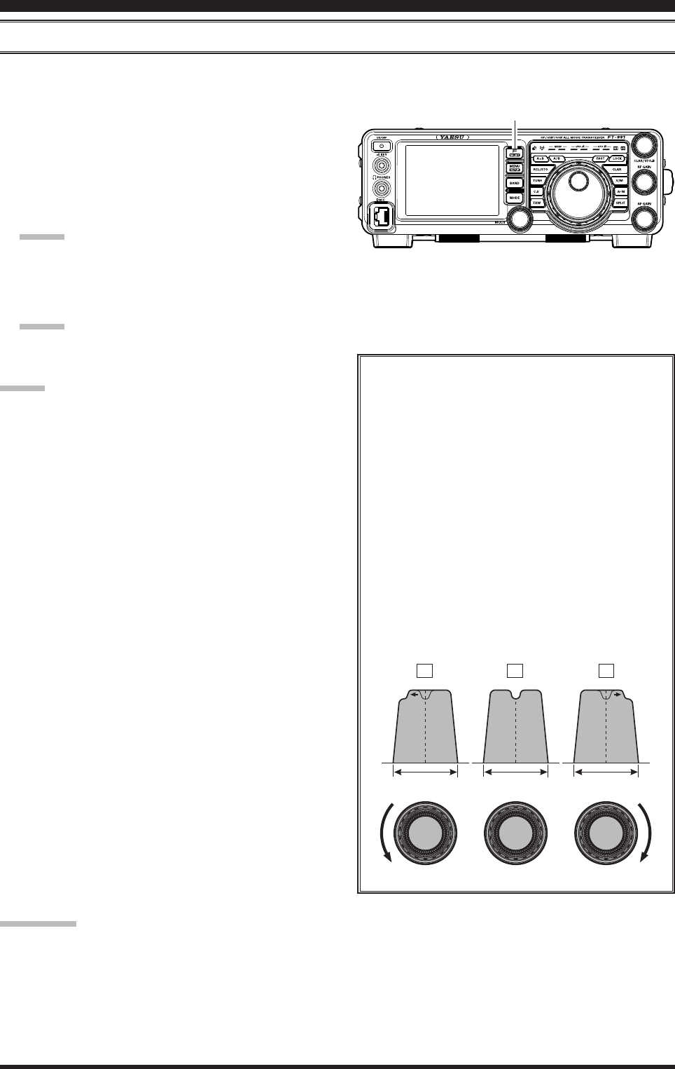
contour control operAtion
The Contour lter system provides a gentle perturbation of the IF lter passband. The Contour is set to either suppress,
or boost specic frequency components, and thus enhances the sound and readability of a received signal.
1. Touch [CONT] displayed by pressing the F(M-
LIST) button to activate the Contour lter. The DSP
graphic display will illuminate and the current “null”
(or “peak”) position of the Contour lter will appear
in the CONTOUR indicator on the display.
2. Rotate the MULTI knob to achieve the most natural-
sounding audio reproduction on the incoming signal.
Advice:
The display will show the Contour frequency when-
ever [CONT] on the LCD is touched.
3. To cancel Contour tuning, touch [CONT] on the
LCD.
Advice:
Alternate touches of [CONT] on the LCD will
switch the Contour lter between on and off.
Advice:
The Contour lter level (either a null or a peak) may
be adjusted using Menu item “112 CONTOUR LEV-
EL”. The factory default setting is for a null of –15
(dB).
The bandwidth over which the Contour lter effect
is applied may be adjusted using Menu item “113
CONTOUR WIDTH”. The factory default setting is
10. When the set value is increased, the bandwidth
becomes wider.
Refer to Figure “B”, this illustrates an “inden-
tation” of the Contour filter in the center of
the passband. The Contour filter places a low-
Q “notch” in the passband, per the settings of
Menu items “112 CONTOUR LEVEL” and “113
CONTOUR WIDTH” (referenced above). Counter-
clockwise rotation (to the left) of the MULTI
knob causes the notch to move toward a lower
frequency within the passband, while clockwise
rotation (to the right) causes the notch to move
toward a higher frequency within the passband.
By removing interference or unwanted frequency
components of the incoming signal, it is possible
to make the desired signal rise out of the back-
ground noise/interference, enhancing intelligibil-
ity.
quick point:
By judicious use of the Contour lter, the “shoulder” of the passband response may be altered, or components may be
removed from within the passband, allowing the desired signal to rise above the background noise and interference in a
manner not obtainable with other ltering systems.
IF BANDWIDTH IF BANDWIDTH IF BANDWIDTH
MULTI MULTI MULTI
A B C
F(M-LIST) Button
Page 39FT-991 OperaTing Manual
IF BANDWIDTH
Desired Signal Desired Signal Desired Signal
QRMQRM
IF BANDWIDTH IF BANDWIDTH
MULTI MULTI MULTI
inTerferenCe reJeCTion
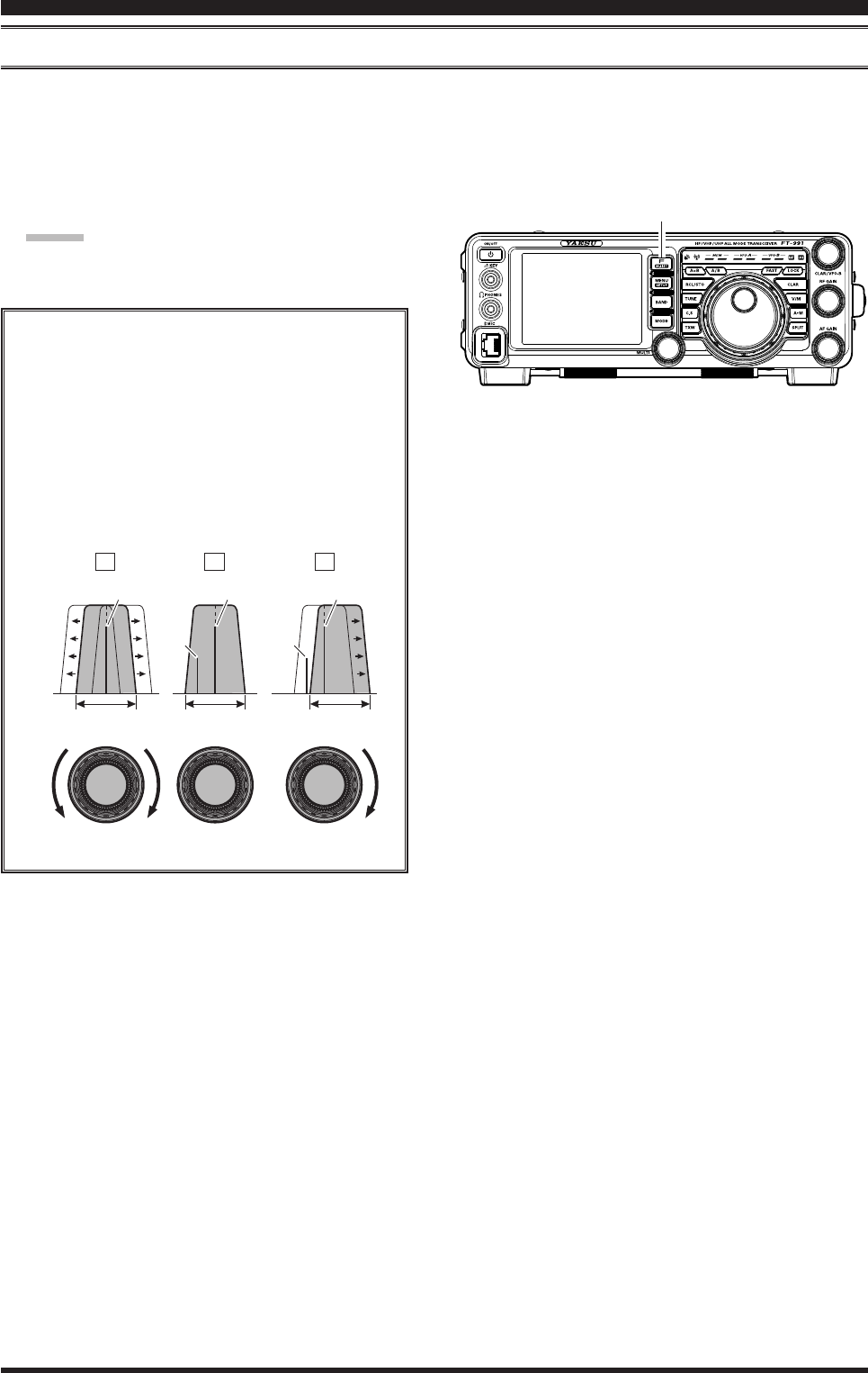
iF ShiFt operAtion (SSb/cw/rtty/pkt ModeS)
IF SHIFT allows you to move the DSP lter passband higher or lower, without changing the pitch of the incoming sig-
nal, and thus reduces or eliminates interference. Because the carrier tuning frequency is not varied, there is no need to
re-tune the operating frequency to eliminate the interference. The total passband tuning range for the IF SHIFT system
is ±1 kHz.
1. Touch
[SHIFT] displayed by pressing the F(M-
LIST) button repeatedly to reduce the interference.
Advice:
The display will show the shift value of the IF
SHIFT whenever [SHIFT] on the LCD is touched.
Referring to Figure “A”, note the depiction of the
IF DSP lter as the thick line, with MULTI knob
in the 12 o’clock position. In Figure “B”, an in-
terfering signal has appeared inside the original
passband. In Figure “C”, you can see the effect
of rotating the MULTI knob. The interference
level is reduced by moving the lter passband so
that the interference is outside of the passband.
A B C
F(M-LIST) Button
Page 40 FT-991 OperaTing Manual
A B C
inTerferenCe reJeCTion
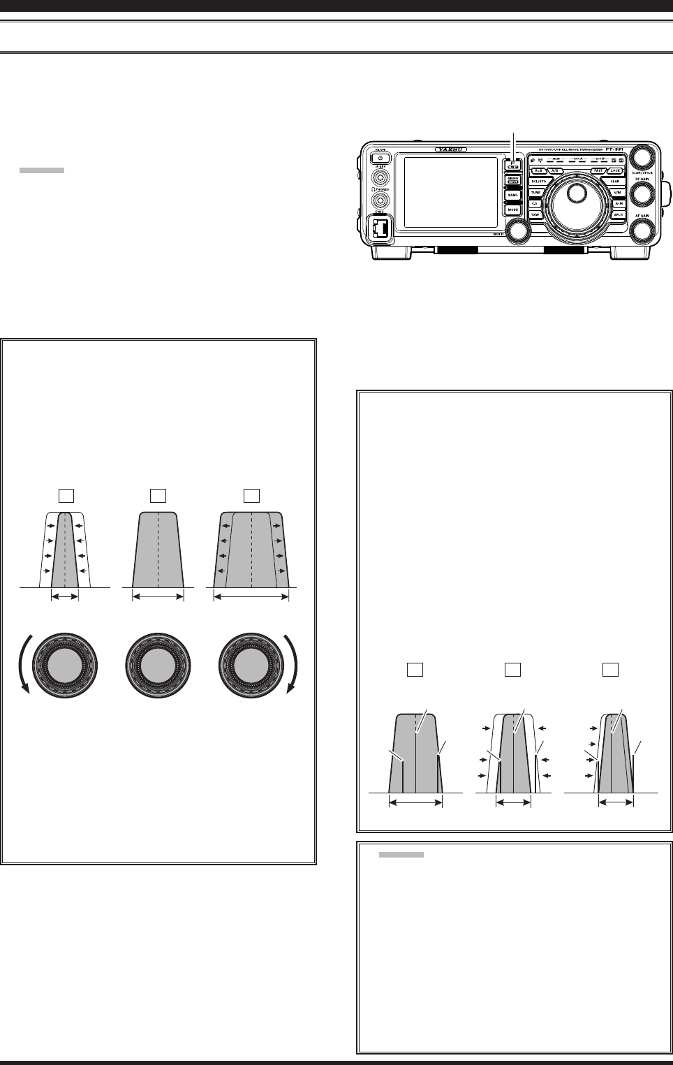
width (iF dSp bAndwidth) tuning (SSb/cw/rtty/dAtA ModeS)
The IF WIDTH tuning system allows you to vary the width of the DSP IF passband, to reduce or eliminate interference.
Moreover, the bandwidth may actually be expanded from its default setting, should you wish to enhance incoming sig-
nal delity when interference on the band is low.
1. Touch
[WIDTH] displayed by pressing the F(M-
LIST) button repeatedly to reduce the interference.
Advice:
The frequency display will show the bandwidth of
the IF passband whenever [WIDTH] is touched.
Referring to Figure “B”, you can see the default
bandwidth on the SSB mode.
By rotating the MULTI knob to the left, the band-
width will narrow (see Figure “A”, while rotation
of the MULTI knob to the right, as depicted in
Figure “C”, will increase the bandwidth.
A B C
The default bandwidths, and total bandwidth ad-
justment range, will vary according to the operat-
ing mode:
SSB Mode: 1.8 kHz ~ 4.0 kHz (default: 2.4 kHz).
CW Mode: 500 Hz ~ 2.4 kHz (default: 2.4 kHz)
RTTY/DATA Modes: 500 Hz ~ 2.4 kHz (default:
500 Hz)
Using IF SHIFT and WIDTH Together
The IF SHIFT and Variable IF WIDTH features
together form a very effective interference-ght-
ing ltering system.
For example, in Figure “A”, you can see how in-
terference has appeared both on the high and low
sides of the desired signal. Touch [WIDTH] on
the LCD, the interference from one side can be
eliminated (Figure “B”). Next, rotate the MULTI
knob to re-position the passband (Figure “C”),
the interference on the opposite side can be re-
moved, without re-introducing the interference
previously eliminated in Figure “B”.
Advice:
For best interference reduction, the WIDTH and
SHIFT features are the primary tools you should
use, after narrowing the bandwidth (WIDTH)
and/or adjusting the center of the passband
(SHIFT). The Contour control may then yield
additional signal-enhancement benefits on
the net residual bandwidth. Even more, the IF
NOTCH Filter (described later) may also be
used, in conjunction with these lter systems, to
signicant advantage.
IF BANDWIDTH IF BANDWIDTH IF BANDWIDTH
MULTI MULTI MULTI Desired Signal Desired Signal Desired Signal
QRM
QRM
QRM
QRM
QRM
QRM
IF BANDWIDTH IF BANDWIDTH IF BANDWIDTH
F(M-LIST) Button
Page 41FT-991 OperaTing Manual
operAting Mode
SSB
CW
RTTY/DATA
AM
FM
(
28/50/144/430
MHz Bands
)
inTerferenCe reJeCTion
nArrow (nAr) one-touch iF Filter Selection
Touching [NAR/WIDE] displayed by pressing the F(M-LIST) button provides one-touch, mode-specic, selection of a
narrow IF DSP lter setting that does not require resetting the bandwidth control to the WIDTH/SHIFT system.
Touching [NAR/WIDE] on the LCD once more returns
the bandwidth control to the WIDTH/SHIFT system.
The factory default bandwidths are:
: Depends on the [WIDTH] setting
( ): Default Bandwidth
“on”
200 Hz ~ 1.8 kHz
(1.5 kHz)
50 ~ 500 Hz
(500 Hz)
50 ~ 500 Hz
(300 Hz)
6 kHz
9 kHz
“oFF”
1.8 ~ 3.0 kHz
(2.4 kHz)
500 Hz ~ 3.0 kHz
(2.4 kHz)
500 Hz ~ 2.4 kHz
(500 Hz)
9 kHz
16 kHz
[nAr/wide] touch key
Advice:
When the narrow bandwidth is selected, the “NAR”
icon will appear in the display.
If
[NAR/WIDE] on the LCD has been touched to
engage the narrow lter, you may still adjust the nar-
row IF bandwidth with [WIDTH] on the LCD and
the MULTI knob. The IF SHIFT is also operational.
When you touch [NAR/WIDE] on the LCD in the
FM mode, both transmit and receive bandwidths are
narrowed.
F(M-LIST) Button