Yaesu Musen 20575X50 HF / VHF / UHF All Mode Transceiver User Manual FT 991
Yaesu Musen Co., Ltd. HF / VHF / UHF All Mode Transceiver FT 991
Contents
- 1. Users Manual Part 1 Rev 1
- 2. Users Manual Part 2
- 3. TempConfidential_05_User_Manual_scope_function_only
Users Manual Part 2
Page 42 FT-991 OperaTing Manual
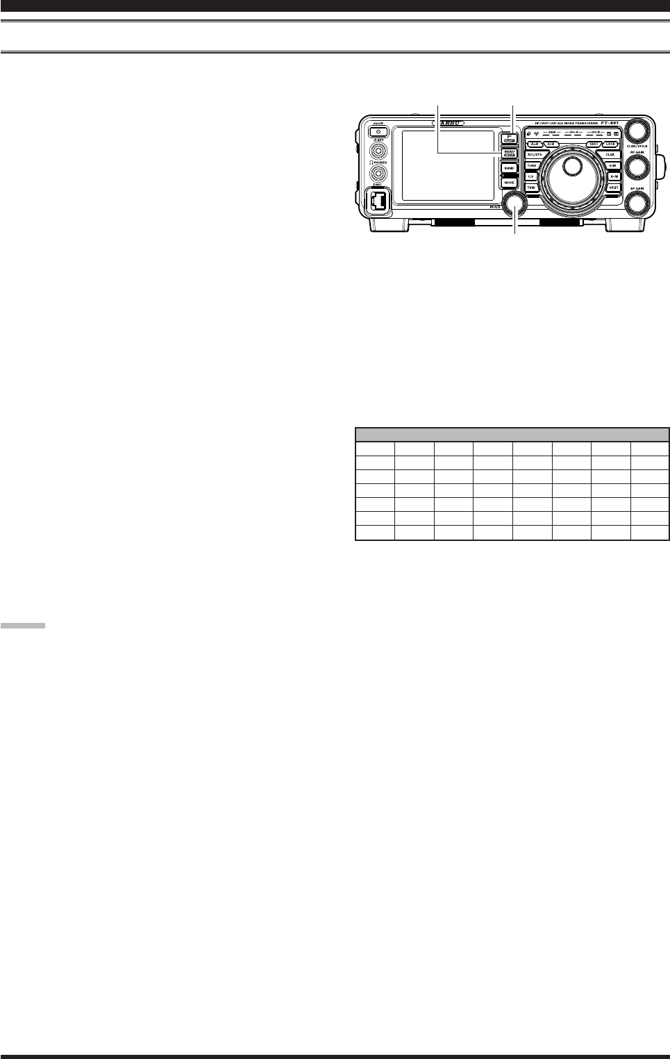
inTerferenCe reJeCTion
iF notch Filter operAtion (SSb/cw/rtty/dAtA/AM ModeS)
The IF NOTCH lter is a highly effective system that allows you to slice out an interfering beat note or other carrier
signal from inside the receiver passband.
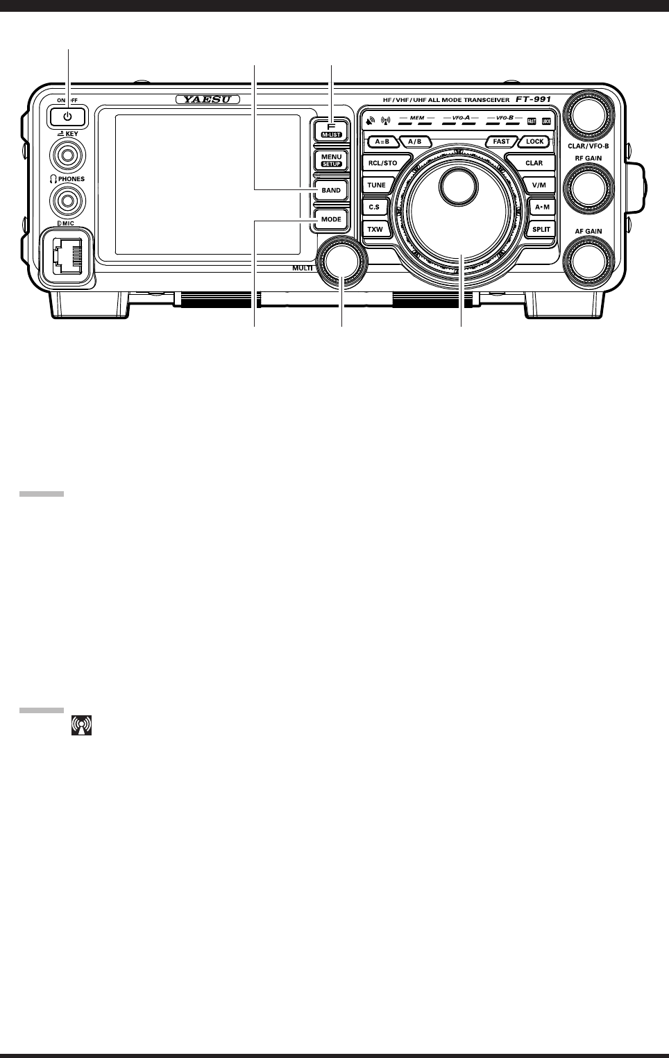
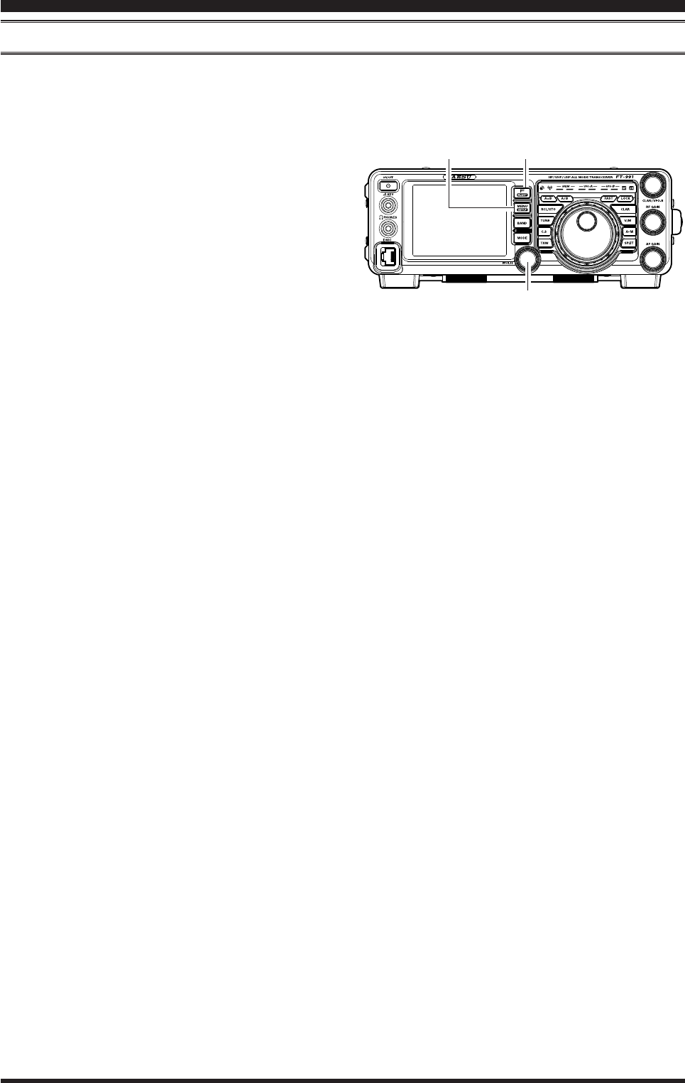
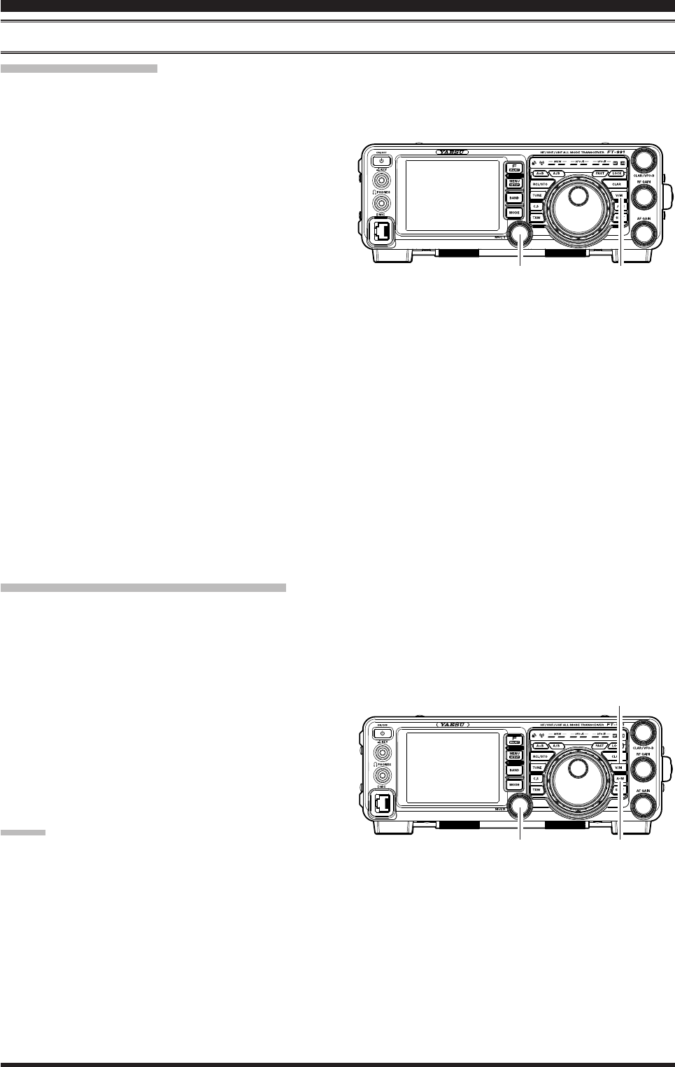
1. Press the F(M-LIST) button, then touch [NOTCH]
on the LCD to activate the Notch filter. The DSP
graphic display will illuminate and the current “null”
position of the NOTCH filter will appear in the
NOTCH indicator on the display. The MULTI knob
functions as the Notch adjustment knob.
2. Rotate the MULTI knob to adjust the “null” position
of the Notch lter.
3. To cancel the NOTCH filter, touch [NOTCH] on
the LCD. The graphic disappears from the NOTCH
indicator on the display, conrming that the NOTCH
lter is no longer in operation.
Advice:
Alternate touches of [NOTCH], will switch the
NOTCH lter between on and off.
Advice:
The bandwidth of the NOTCH lter (either narrow
or wide) may be adjusted using Menu item “114
IF NOTCH WIDTH”. The factory default setting is
“WIDE”.
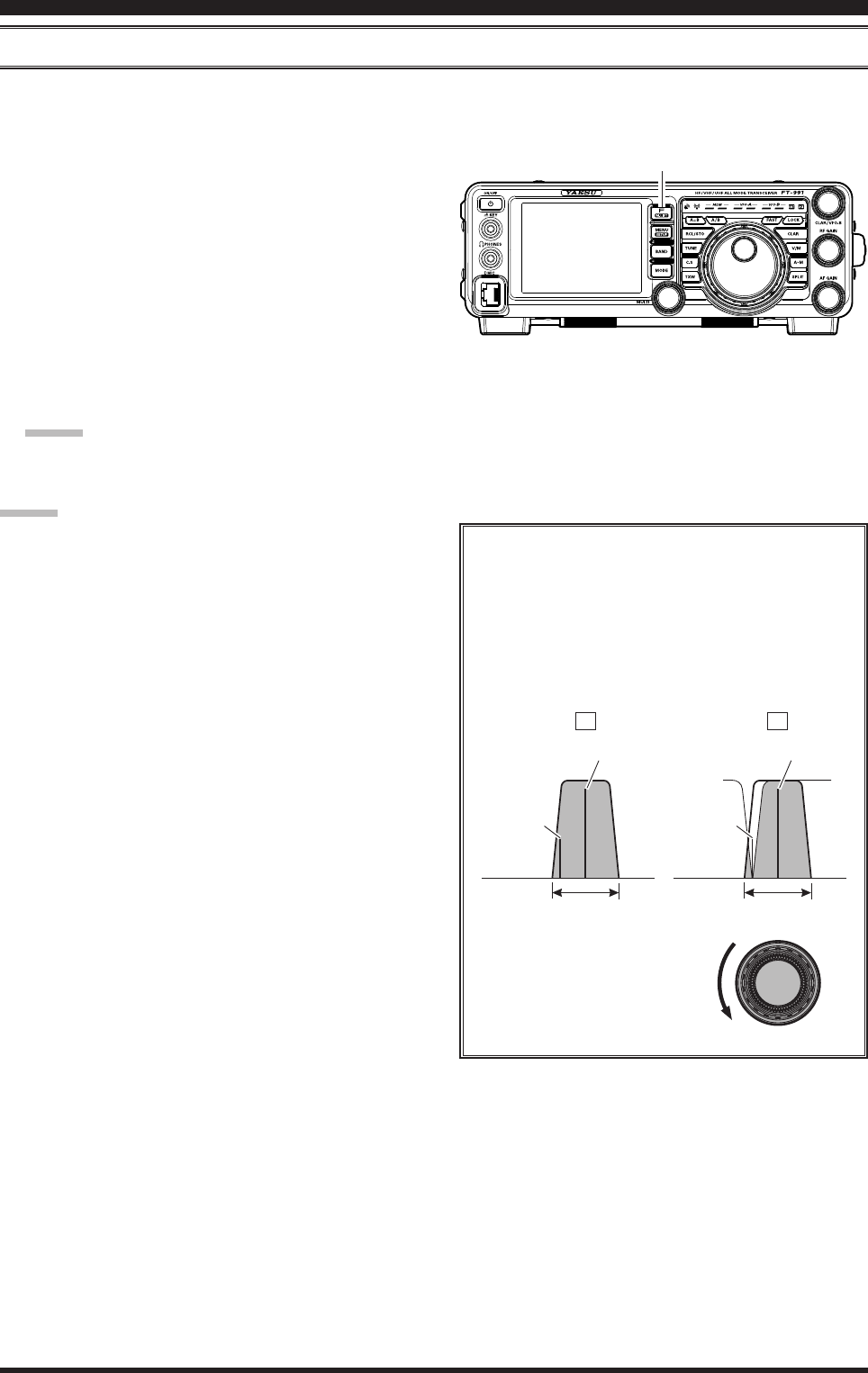
The performance of the IF NOTCH lter is illus-
trated in Figure “A”, where the effect of rotation
of the MULTI knob is depicted. In Figure “B”
you can see the notching effect of the IF NOTCH
lter as you rotate the MULTI knob to eliminate
the interfering heterodyne.
A B
Desired Signal Desired Signal
QRM
(Heterodyne)
QRM
(Heterodyne)
IF BANDWIDTH IF BANDWIDTH
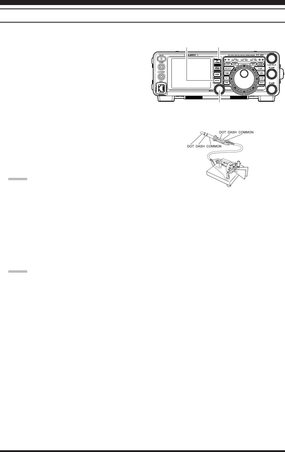
MULTI
F(M-LIST) Button
Page 43FT-991 OperaTing Manual
digitAl notch Filter (dnF) operAtion
The Digital NOTCH Filter (DNF) is an effective beat-canceling lter that can null out a number of interfering beat notes
inside the receiver passband. Because this is an Auto-Notch feature, there is no adjustment knob associated with this l-
ter.
Advice:
If a very strong interfering carrier is encountered, we recommend you rst use the IF NOTCH lter, as it is the most ef-
fective notching tool in the receiver section.
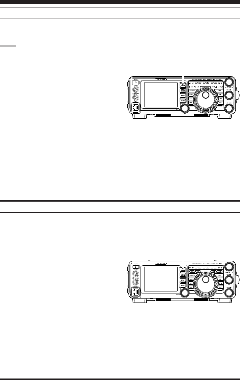
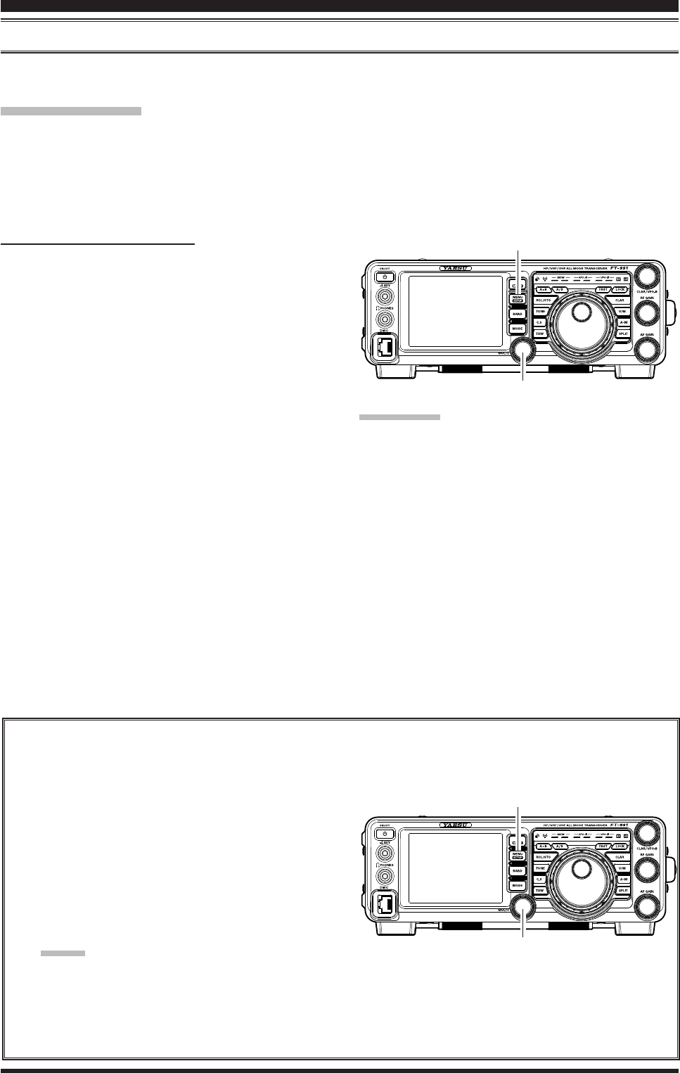
1. Press the F(M-LIST) button, then touch [DNF] on
the LCD. The “DNF” will appear in the display.
To disable the Digital NOTCH Filter, just repeat the
above procedure, touching [DNF] on the LCD to choose
“OFF”. The “DNF” will turn off, confirming that the
Digital NOTCH Filter is not active.
digitAl noiSe reduction (dnr) operAtion
The Digital Noise Reduction (DNR) system is designed to reduce the level of random noise found on the HF and 50
MHz bands, and it is especially effective during SSB operation. By setting the Menu item “110 DNR LEVEL”, any of 15
different noise-reduction algorithms can be selected; each of these algorithms was created for dealing with a different
noise prole. You will want to experiment with the DNR system to nd the best setting corresponding to the noise cur-
rently being experienced.
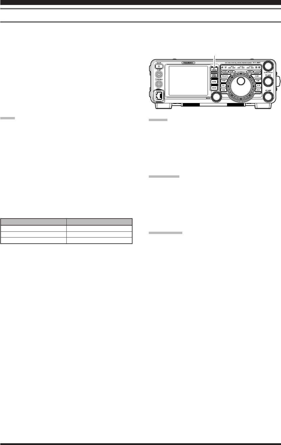
1. Press the F(M-LIST) button, then touch [DNR] on
the LCD. The “DNR” will appear in the display.
To disable the DNR system, just repeat the above proce-
dure, touching [DNR] on the LCD to choose “OFF”. The
“DNR” will turn off, conrming that the DNR system is
not active.
inTerferenCe reJeCTion
F(M-LIST) Button
F(M-LIST) Button

Page 44 FT-991 OperaTing Manual
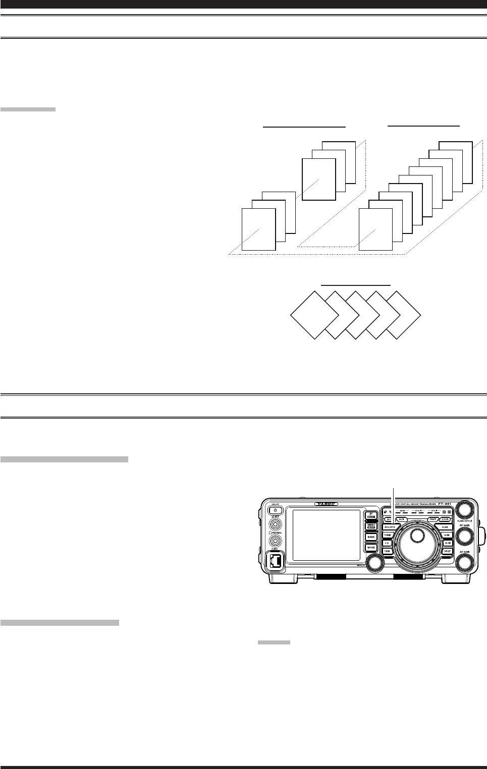
Tools for CoMforTable and effeCTive reCepTion
rF gAin
The RF Gain control provides manual adjustment of the gain levels for the receiver RF and IF stages, to account for
noise and signal strength conditions at the moment.
1. The
RF GAIN knob should, initially, be rotated to
the fully clockwise position. This is the point of
maximum sensitivity.
2. Counter-clockwise rotation of the RF GAIN knob
will gradually reduce the system gain.
Advice:
As the RF GAIN knob is rotated counterclockwise
to reduce the gain, the S-meter reading will rise. This
indicates that the AGC voltage being applied to the
receiver is increasing (this causes a reduction in re-
ceiver gain).
Rotating the RF GAIN knob control to the fully
counter-clockwise position will essentially disable
the receiver, as the gain will be greatly reduced. In
this case, the S-meter will appear to be “pegged”
against the right edge of the analog S-meter scale.
quick point:
Reception frequently can be optimized by rotating
the RF GAIN knob slightly counter-clockwise to the
point where the “stationary” meter indication is set
just about the same as the incoming noise level. This
will reduce the RF gain to nd a level of improved
signal to noise ratio.
The RF Gain control, along with the IPO and the At-
tenuator features, all affect the system receiver gain
in different ways. The IPO generally should be the
rst feature engaged when dealing with a high noise
level, or a crowded, high-level signal environment.
Also, the IPO generally should be the first feature
engaged, if the frequency is low enough to allow the
preamplier to be bypassed. Thereafter, the RF Gain
and Attenuator features may be employed to provide
precise, delicate adjustment of the receiver gain to
fully optimize performance.
RF GAIN Knob

Page 45FT-991 OperaTing Manual
Tools for CoMforTable and effeCTive reCepTion
Audio peAk Filter
1. Press the F(M-LIST) button, then touch [APF] on
the LCD. The “APF” indicator will appear in the
DSP display.
Advice:
When APF is engaged, the peak position of the APF
is depicted graphically in the NOTCH indicator on
the display.
2. Touch
[AFP] on the LCD again to disable the APF.
Advice:
The APF may only be activated while the transceiver is
in CW mode.
F(M-LIST) Button
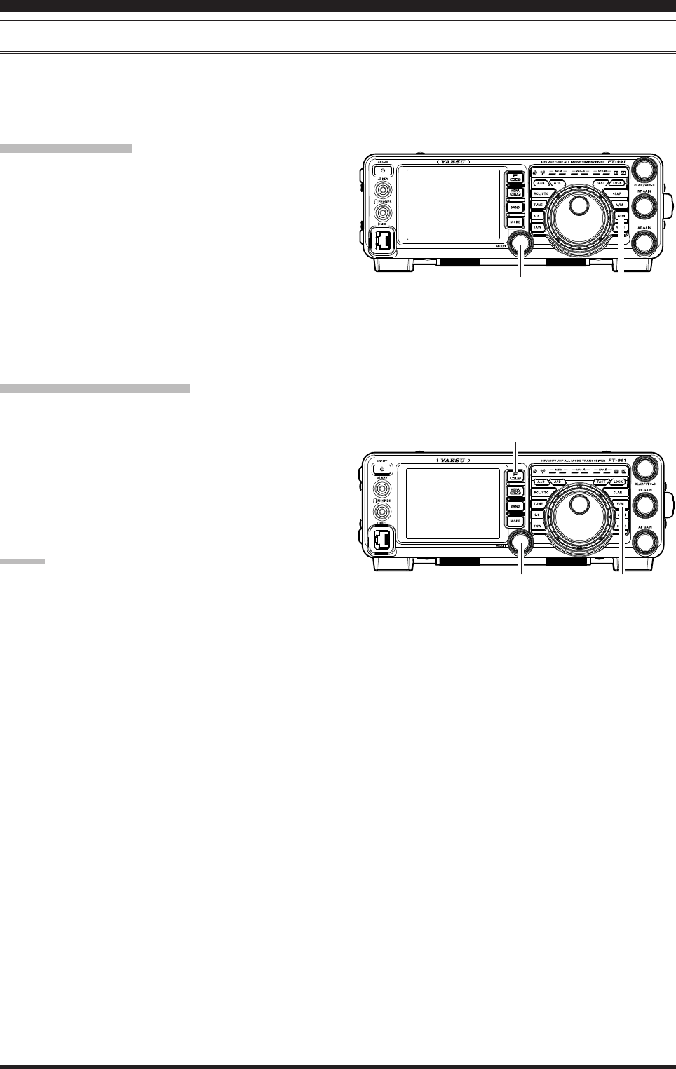
Page 46 FT-991 OperaTing Manual
Agc (AutoMAtic gAin control)
The AGC system is designed to help compensate for fading and other propagation effects. The AGC characteristics can
be individually set for each operating mode. The basic objective of AGC is to maintain a constant audio output level
once a certain minimum threshold of signal strength is achieved.
Press the F(M-LIST) button, then touch [AGC] on the
LCD repeatedly to select the desired receiver-recovery
time constant. You will observe the AGC status notation
in the AGC column of the Key Function Display on the
TFT display, denoting the AGC receiver-recovery time
currently in use. For most operations, we recommend
the “AUTO” mode. Additionally, you may disable the
AGC by touching [AGC] on the LCD.
note:
The “AUTO” selection mode selects the optimum
receiver-recovery time for the reception mode.
In this case, the selected receiver-recovery time in
the AGC column of the Key Function Display glows
green (Normally glows blue).
Touching
[AGC] on the LCD allows selection of the
desired receiver-recovery time constant. Normally,
the “AUTO” selection is satisfactory for most situ-
ations, but in the event of operation on a crowded
band where you wish to receive a weak signal, you
may wish to change the setting to FAST. The AUTO
mode selections are:
Tools for CoMforTable and effeCTive reCepTion
Advice:
If the AGC receiver-recovery time is set to “Off” by
touching [AGC] on the LCD, the S-meter will no
longer deect. Additionally, you will likely encoun-
ter distortion on stronger signals, as the IF ampliers
and the following stages are probably being over-
loaded.
quick point:
Several aspects of AGC performance may be congured
via the Menu. However, because AGC can have such a
profound impact on overall receiver performance, we
generally do not recommend any changes to the AGC
Menu selections until you are thoroughly familiar with
the performance of the FT-991.
terMinology:
Automatic Gain Control, or AGC, is a circuit that senses
the received signal strength, and then limits the gain of
the RF and IF stages to keep the output audio volume at
a more-or-less constant level. AGC also protects the RF,
IF, Audio, and DSP stages from overload, as it limits the
signal strength that is allowed to ow, irrespective of the
input signal level.
Auto Agc Selection
SLOW
FAST
MID
operAting Mode
LSB/USB/AM
CW/FM
RTTY/DATA
F(M-LIST) Button
Page 47FT-991 OperaTing Manual
AdjuStAble receiver Audio Filter
The FT-991 includes an adjustable receiver audio lter, that provides precise, independent control of the low; and upper
audio ranges.
Tools for CoMforTable and effeCTive reCepTion
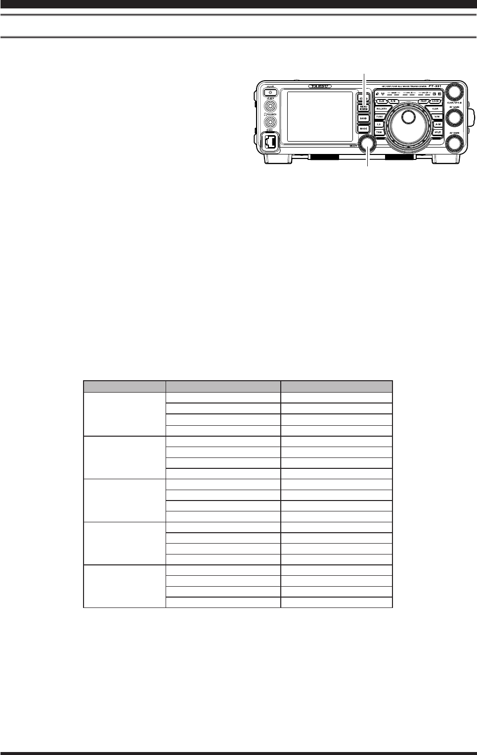
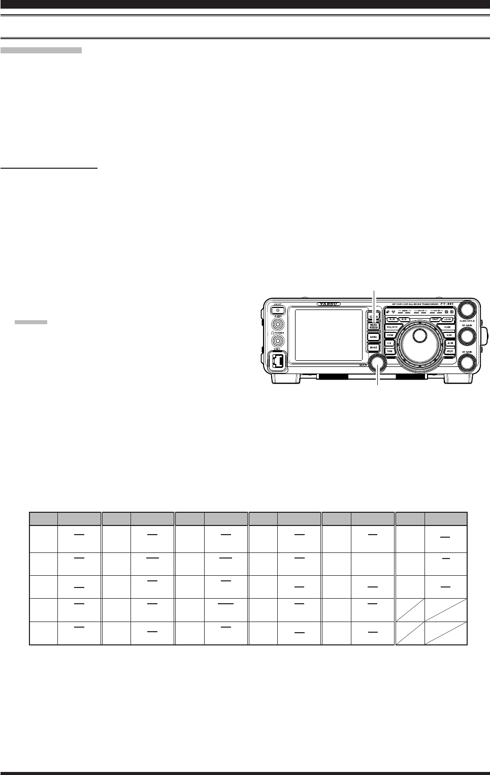
1. Press the MENU button to enter the Menu mode.
2. Rotate the MULTI knob to nd Menu items “040”
through “043” these parameters apply to the adjust-
ment of the receiver audio filter in the AM mode,
Menu items “050” through “053” apply to the
adjustment of the RX audio lter in the CW mode,
Menu items “067” through “070” apply to the ad-
justment of the RX audio lter in the DATA mode,
Menu items “092” through “095” apply to the ad-
justment of the RX audio lter in the RTTY mode,
and Menu items “102” through “105” apply to the
adjustment of the RX audio lter in the SSB mode
3. Touch
[SELECT] on the LCD.
4. Rotate the MULTI knob to adjust the receiver audio
response as desired.
5. Touch
[ENTER] on the LCD to save the new set-
ting.
6. Press the MENU button or touch [BACK] on the
LCD to exit to normal operation.
Mode Menu iteM AvAilAble vAlueS
AM
040 AM LCUT FREQ OFF/100(Hz) ~ 1000(Hz)
041 AM LCUT SLOPE 6dB/oct / 18dB/oct
042 AM HCUT FREQ 700(Hz) ~ 4000(Hz)/OFF
043 AM HCUT SLOPE 6dB/oct / 18dB/oct
CW
050 CW LCUT FREQ OFF/100(Hz) ~ 1000(Hz)
051 CW LCUT SLOPE 6dB/oct / 18dB/oct
052 CW HCUT FREQ 700(Hz) ~ 4000(Hz)/OFF
053 CW HCUT SLOPE 6dB/oct / 18dB/oct
DATA
067 DATA LCUT FREQ OFF/100(Hz) ~ 1000(Hz)
068 DATA LCUT SLOPE 6dB/oct / 18dB/oct
069 DATA HCUT FREQ 700(Hz) ~ 4000(Hz)/OFF
070 DATA HCUT SLOPE 6dB/oct / 18dB/oct
RTTY
092 RTTY LCUT FREQ OFF/100(Hz) ~ 1000(Hz)
093 RTTY LCUT SLOPE 6dB/oct / 18dB/oct
094 RTTY HCUT FREQ 700(Hz) ~ 4000(Hz)/OFF
095 RTTY HCUT SLOPE 6dB/oct / 18dB/oct
SSB
102 SSB LCUT FREQ OFF/100(Hz) ~ 1000(Hz)
103 SSB LCUT SLOPE 6dB/oct / 18dB/oct
104 SSB HCUT FREQ 700(Hz) ~ 4000(Hz)/OFF
105 SSB HCUT SLOPE 6dB/oct / 18dB/oct
MULTI Knob
MENU Button
Page 48 FT-991 OperaTing Manual
1. Press the BAND button to shown the band list, then
touch a band key corresponding to the Amateur band
on which you wish to operate.
2. Press the MODE button to show the mode list, then
select the operating mode by touching the corre-
sponding key.
Advice:
By convention, LSB is used in the 7 MHz and lower
Amateur bands for SSB communication, and USB is
used on the 14 MHz and higher bands (the 10 MHz
band is used for CW and data modes only).
3. Rotate the Main Tuning Dial knob to adjust the op-
erating frequency. Alternately, you may use the UP/
DWN scanning buttons on the MH-31A8J Hand Mi-
crophone to sweep up or down the current band.
4. Press the microphone PTT (Push To Talk) switch to
begin transmission; speak into the microphone in a
normal voice level.
Advice:
The “ ” indicator will light up in the LED in-
dicators area, conrming that transmission is in
progress.
When transmitting in the AM mode, set a maxi-
mum (carrier) power output of 25 Watts via
[PROC] displayed by pressing the F(M-LIST)
button.
5. Adjust the microphone amplier gain to match the
microphone and your voice level: Touch [METER]
on the LCD repeatedly to select the “ALC”.
Press and hold the PTT switch, and speak into the
microphone in a normal voice level.
In the SSB mode, touch [MIC GAIN] and then ad-
just MULTI knob so that the ALC meter stays within
the ALC zone of the meter (up to half scale deec-
tion) on voice peaks.
In the AM mode, touch [MIC GAIN] and then adjust
MULTI knob so that the ALC meter does not deect
at voice peaks.
6. Release the PTT switch at the end of your transmis-
sion. The transceiver will return to the receive mode.
ssb/aM Mode TransMission
ON/OFF Switch
Main Tuning Dial Knob
F(M-LIST) Button
MULTI KnobMODE Button
BAND Button

Page 49
FT-991 OperaTing Manual
ssb/aM Mode TransMission
Advice:
ALC meter deection may be caused by excessive
drive power, but also by reflected power detected
in the antenna system. If the impedance presented
to the transceiver is other than 50 Ohms, ALC me-
ter action may be observed that is not related to the
proper setting of [MIC GAIN] on the LCD. There-
fore, we recommend that you make [MIC GAIN]
adjustments into a dummy load or antenna system
presenting impedance very close to 50 Ohms.
When performing “on air” tests (such as the setup of
microphone gain), be sure to check the frequency be-
fore transmitting, to avoid interference to others who
may already be using the frequency.
Four techniques for exercising Transmit/Receive
control are provided on the FT-991. You may
choose the technique(s) that best suit your operating
needs:
Pressing the microphone PTT switch will engage
the transmitter.
The rear panel PTT jack may be connected to a
foot switch or other manual switching device in
order to engage the transmitter.
Touching
[MOX] displayed by pressing the F(M-
LIST) button will lock the transmitter on. Touch
[MOX] on the LCD again to return to receive.
The VOX (Voice Operated Xmit) circuit will
engage the transmitter automatically when you
speak into the microphone. For details of VOX
operation refer to page ##.
Page 50 FT-991 OperaTing Manual
The Automatic Antenna Tuner (hereinafter referred to as the “ATU”) built into each FT-991 is designed to ensure a 50-
Ohm load for the nal amplier stage of the transmitter. We recommend that the ATU be used whenever you operate on
the FT-991.
Advice:
Because the ATU of the FT-991 is located inside the station, it only adjusts the impedance presented to the trans-
ceiver at the station end of your coaxial cable feedline. It does not “tune” the SWR at the antenna feed point itself.
When designing and building your antenna system, we recommend that every effort be made to ensure a low SWR
at the antenna feed point.
The ATU of the FT-991 includes 100 memories for tuning data. Eleven of these memories are allocated, one per
Amateur band, so that each band has at least one setting preset for use on that band. The remaining 89 memories are
reserved for the 89 most-recent tuning points, for quick frequency change without the need to retune the ATU.
The ATU in the FT-991 is designed to match impedances within the range of 16.5 Ohms to 150 Ohms, correspond-
ing to an SWR of 3:1 or less on the 160 through 6 meter amateur bands. Accordingly, simple non-resonant whip an-
tennas, along with random-length wires and the “G5RV” antenna (on most bands) may not be within the impedance
matching range of the ATU.
Atu operAtion
using The auToMaTiC anTenna Tuner
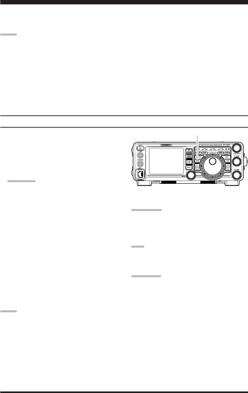
1. Use the Main Tuning Dial knob to set the radio to
the desired operating frequency within the Amateur
band.
2. Press the TUNE button momentarily to place the
ATU in the transmit line (no adjustment/tuning will
occur yet). The “TUNER” icon will appear in the
display.
quick point:
The momentary press of the TUNE button will turn
the tuner on, and the microprocessor will automati-
cally select the tuning point closest to the current
operating frequency.
3. Press and hold in the TUNE button for one second to
begin automatic tuning. The transmitter will be en-
gaged, and the “TUNER” icon will blink while tun-
ing is in progress. When the optimum tuning point
has been reached, the radio will return to receive,
and the “TUNER” icon will again glow steadily (in-
stead of blinking).
4. To disconnect the ATU from the transmit line, press
the TUNE button momentarily. The “TUNER”
icon will turn off, conrming that the ATU has been
turned off. In the “Off” mode, the transceiver will be
directly connected to the coaxial cable connected to
your antenna, and will respond to whatever imped-
ance is present at the station end of the coax.
Advice:
The ATU circuit is located between the nal amplier
and the rear-panel antenna jack; reception is not affected
by the ATU.
quick pointS:
As shipped from the factory, only one ATU alignment
point is saved on each Amateur band. This was memo-
rized during the nal alignment and performance veri-
cation stages on the production line.
note:
Please check the operating frequency before beginning
the tuning process, to be sure you are not interfering
with others who may already be using the frequency.
terMinology:
Antenna Tuner Memories: The microprocessor of the
ATU makes a note of the selected tuning capacitors and
inductors, and stores the data for each 10 kHz window
in which tuning has occurred. This eliminates the need
to re-tune every time you return to a frequency on which
you have already completed the tuning process.
TUNE Button
Page 51
FT-991 OperaTing Manual
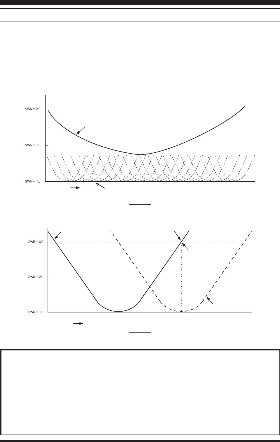
About Atu operAtion
Figure 1 depicts a situation where normal tuning via the ATU has been successfully completed, and the tuning data has
been stored in the ATU memory. The antenna system as seen by the transmitter is shown.
In Figure 2, the operator has changed frequency, and the “HI-SWR” icon has appeared. The operator presses and holds
in the TUNE button for two seconds to begin impedance matching using the ATU.
If a high SWR condition exists (above 3:1), corrective action must be taken in the antenna system to bring the imped-
ance closer to 50 Ohms. The ATU will refuse to memorize settings on frequencies where the SWR exceeds 3:1. A High
SWR may indicate a mechanical failure in the feed system, and can lead to the generation of spurious signals causing
TVI, etc.
About ATU Memories
SWR (After tuning) Less than 1.5:1
The tuner settings are stored in the ATU memory.
SWR (After tuning) Greater than 1.5:1
Tuning data will not be retained in memory. If you return to the same frequency, the tuning process must be re-
peated.
SWR (After tuning) Greater than 3:1
The “HI-SWR” icon will light up, and the tuner settings, if achieved, will not be memorized. Please investigate
the high SWR condition and resolve the problem before attempting further operation using this antenna.
using The auToMaTiC anTenna Tuner
Figure 1
Figure 2
Feed Point SWR
SWR: 3.0
Retuned Setting
Memorized ATU Tuning
The “HI-SWR” icon appears on the display
when you transmit on the frequency
SWR after ATU Tuning
Frequency
Frequency
Page 52 FT-991 OperaTing Manual
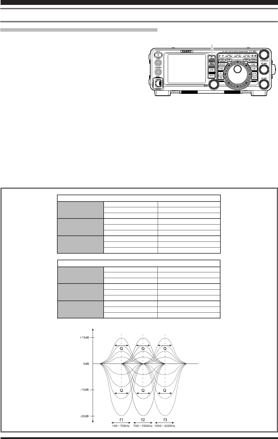
PArAMetric Microphone equAlizer (SSb/AM/FM Mode)
The FT-991 includes a unique Three-Band Parametric Microphone Equalizer that provides precise, independent control
over the low, mid and treble ranges in your voice waveform. You may utilize one group of settings when the speech
processor is off and an alternate group of settings when the speech processor is on. The speech processor feature is de-
scribed in the next chapter.
quick point:
The Parametric Equalizer is a unique technique for adjusting the signal quality. The three audio ranges may be adjusted
so precisely, it is possible to craft an audio response that provides a natural and pleasant sound that you may not have
ever experienced before. Alternately, the effective “talk power” can be signicantly enhanced.
The aspects of conguration that you may adjust on the Parametric Equalizer are:
Center Frequency: The center frequency of each of the three bands may be adjusted.
Gain: The amount of enhancement (or suppression) within each band may be adjusted.
Q: The bandwidth over which the equalization is applied may be adjusted.
Setup of the Parametric Microphone Equalizer
1. Connect the microphone to the MIC jack.
2. Set the RF output power to minimum value.
Advice:
We recommend that you connect a dummy load
to one of the Antenna jacks, and monitor your
signal on a separate receiver, to prevent interfer-
ence to other users.
You will have the best chance of hearing the ef-
fects of adjustments if you wear headphones
(connected to the monitor receiver) while listen-
ing to your transmitted signal.
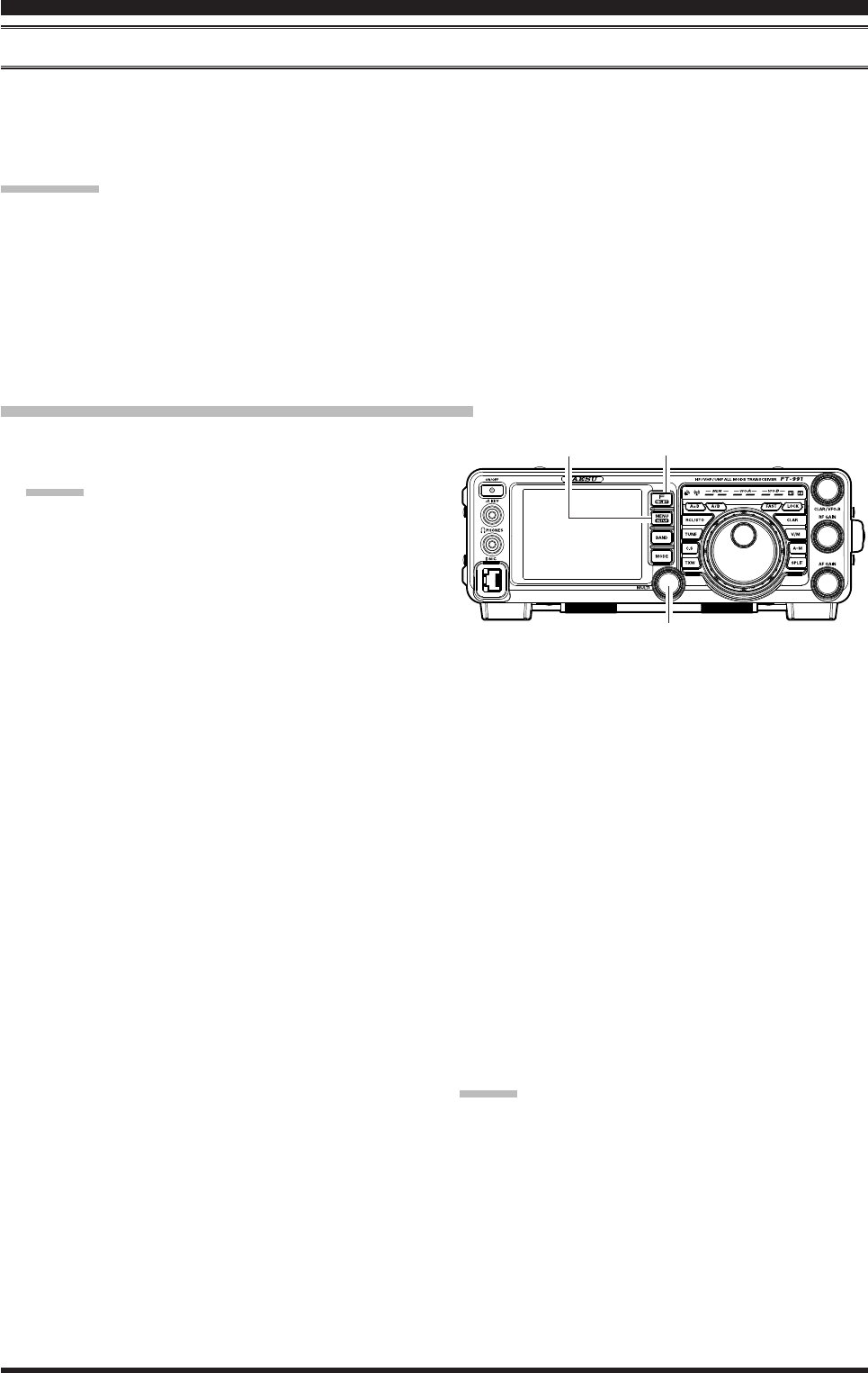
3. To adjust the Parametric Microphone Equalizer
while the speech processor is disabled, press the
F(M-LIST) button, then touch [MIC-EQ] to select
“ON”.
To adjust the Parametric Microphone Equalizer with
the speech processor engaged, press the F(M-LIST)
button, then touch [PROC] to select “ON”.
7. Touch
[SELECT] on the LCD, then rotate the
MULT knob to perform adjustments to a particular
Menu item.
8. Press and hold the PTT switch, and speak into
the microphone while listening to the effect of the
changes you are making. Because the overall effect
on the sound will change with each adjustment, you
should make several passes through each adjustment
area, to be sure that you are achieving the optimum
settings.
9. When you have completed all adjustments, touch
[ENTER] on the LCD to save the new settings.
10. Press the MENU(SETUP) button or touch [BACK]
on the LCD to exit to normal operation. If you only
touch [BACK] momentarily to exit, none of the
changes you performed will be stored.
Advice:
To roll off excessive bass response in a wide-range stu-
dio microphone, try putting a 10 dB null at 100 Hz with
a bandwidth of “1” or “2”, do about a 3 dB null centered
on 800 Hz with a bandwidth of “3,” and then put an 8
dB peak centered on 2100 Hz with a bandwidth of “1.”
These are starting recommendations; each microphone
and user’s voice will be different, often requiring differ-
ent settings.
enhanCing TransMiT signal QualiTY
MULTI Knob
MENU(SETUP) Button F(M-LIST) Button
4. Touch
[MONI], if you want to listen on the FT-991
internal monitor.
5. Press the MENU(SETUP) button. The Menu list
will appear in the display.
6. Rotate the MULT knob to nd the “EQ” Menu area,
containing Menu items “119” through “127”; these
parameters apply to the adjustment of the Parametric
Microphone Equalizer when the speech processor
is disabled. Menu items “128” through “136” ap-
ply to the adjustment of the Parametric Microphone
Equalizer when the speech processor is engaged.
Page 53
FT-991 OperaTing Manual
enhanCing TransMiT signal QualiTY
pArAMetric Microphone equAlizer (SSb/AM/FM Mode)
Activating the Parametric Microphone Equalizer
1. Adjust
[MIC GAIN] on the LCD, as described on
page ##.
2. Press the F(M-LIST) button, then touch [MIC-EQ]
on the LCD to select “ON”. If you use the Paramet-
ric Microphone Equalizer with the speech processor
engaged, press the F(M-LIST) button, then touch
[PROC] on the LCD to select “ON”.
The “MIC EQ” (and “PROC”) will appear in the
display, conrming that the Parametric Microphone
Equalizer is engaged.
3. Press the PTT switch on the microphone, and speak
into the microphone in a normal voice level.
4. To switch the Parametric Microphone Equalizer off,
touch [MIC-EQ] on the LCD again until the “MIC
EQ” icon disappears.
3-StAge pArAMetric equAlizer AdjuStMentS (Speech proceSSor: “oFF”)
Center Frequency “119 PRMTRC EQ1 FREQ” “100” (Hz) ~ “700” (Hz) / “OFF”
“122 PRMTRC EQ2 FREQ” “700” (Hz) ~ “1500” (Hz) / “OFF”
“125 PRMTRC EQ3 FREQ” “1500” (Hz) ~ “3200” (Hz) / “OFF”
Parametric Gain “120 PRMTRC EQ1 LEVEL” (Low) “–20” (dB) ~ “+10” (dB)
“123 PRMTRC EQ2 LEVEL” (Mid) “–20” (dB) ~ “+10” (dB)
“126 PRMTRC EQ3 LEVEL” (High) “–20” (dB) ~ “+10” (dB)
Q (Bandwidth) “121 PRMTRC EQ1 BWTH” (Low) “1” ~ “10”
“124 PRMTRC EQ2 BWTH” (Mid) “1” ~ “10”
“127 PRMTRC EQ3 BWTH” (High) “1” ~ “10”
Parametric Gain
3-StAge pArAMetric equAlizer AdjuStMentS (Speech proceSSor: “on”)
Center Frequency “128 P-PRMTRC EQ1 FREQ” “100” (Hz) ~ “700” (Hz) / “OFF”
“131 P-PRMTRC EQ2 FREQ” “700” (Hz) ~ “1500” (Hz) / “OFF”
“134 P-PRMTRC EQ3 FREQ” “1500” (Hz) ~ “3200” (Hz) / “OFF”
Parametric Gain “129 P-PRMTRC EQ1 LEVEL” (Low) “–20” (dB) ~ “+10” (dB)
“132 P-PRMTRC EQ2 LEVEL” (Mid) “–20” (dB) ~ “+10” (dB)
“135 P-PRMTRC EQ3 LEVEL” (High) “–20” (dB) ~ “+10” (dB)
Q (Bandwidth) “130 P-PRMTRC EQ1 BWTH” (Low) “1” ~ “10”
“133 P-PRMTRC EQ2 BWTH” (Mid) “1” ~ “10”
“136 P-PRMTRC EQ3 BWTH” (High) “1” ~ “10”
F(M-LIST) Button

Page 54 FT-991 OperaTing Manual
uSing the Speech proceSSor (SSb Mode)
The FT-991 Speech Processor is designed to increase “talk power” by increasing the average power output (via a so-
phisticated compression technique) and adjusting the audio quality to the menu settings (“128 P-PRMTRC EQ1 FREQ”,
“131 P-PRMTRC EQ2 FREQ”, “134 P-PRMTRC EQ3 FREQ”). The result is improved intelligibility when conditions
are difcult.
1. Adjust
[MIC GAIN] on the LCD, as described on
page ##.
2. Touch [METER] on the LCD to select “COMP”
(Compression) meter.
3. Press the F(M-LIST) button, then touch [PROC] on
the LCD to select “ON”.
The “PROC” will appear in the display, conrming
that the Speech Processor is engaged.
4. Press the PTT switch on the microphone, and speak
into the microphone in a normal voice level.
5. Adjust the MULT knob to set the compression level
within the 5 dB to 10 dB range.
6. To switch the Speech Processor off, touch [PROC]
on the LCD once more. The “PROC” will turn off,
conrming that the Speech processor is turned off.
Advice:
You may adjust the Parametric Microphone Equal-
izer when the speech processor is engaged, using
Menu Items “128” through “136”. See page ## for
details.
enhanCing TransMiT signal QualiTY
MULTI Knob
F(M-LIST) Button

Page 55
FT-991 OperaTing Manual
enhanCing TransMiT signal QualiTY
AdjuSting the SSb trAnSMitted bAndwidth (SSb Mode)
For transmission on SSB, a default bandwidth of 2.4 kHz is provided. This bandwidth provides reasonable delity along
with good talk power, and is typical of the bandwidth used for decades for SSB transmission. The bandwidth may be
varied by the operator, to provide different levels of delity or talk power, according to your preferences.
Here are the steps to adjust the SSB transmit bandwidth:
1. Press the MENU(SETUP) button to engage the
Menu.
2. Rotate the MULTI knob to select Menu item “110
SSB TX BPF”.
3. Touch
[SELECT] on the LCD, then rotate the
MULTI knob to select the desired bandwidth. The
available selections are: 100-3000 Hz, 100-2900
Hz, 200-2800 Hz, 300-2700 Hz, and 400-2600 Hz.
The default is 300-2700 Hz. A wider bandwidth will
provide greater fidelity. A narrow bandwidth will
compress the available transmitter power into less
spectrum, resulting in more “talk power” for DX
pile-ups.
4. Touch
[ENTER] on the LCD to save the new set-
ting.
5. Press the MENU(SETUP) button or touch [BACK]
on the LCD to exit to normal operation.
Advice:
The Transmit Monitor function is a very helpful way to
conrm the effect that changing the bandwidth will have
on delity. With [MONI] displayed by pressing the F(M-
LIST) button, you will be able to hear the difference in
sound quality as you make changes.
quick pointS:
The higher delity associated with wide bandwidth will
be particularly enjoyable on the low bands during local
rag-chew QSOs.
MULTI Knob
MENU(SETUP) Button F(M-LIST) Button
Page 56 FT-991 OperaTing Manual
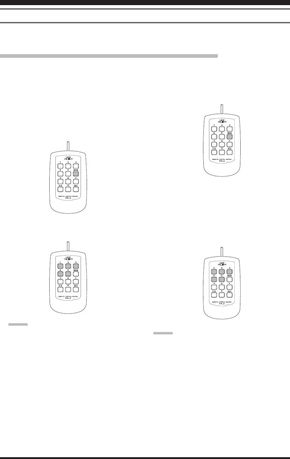
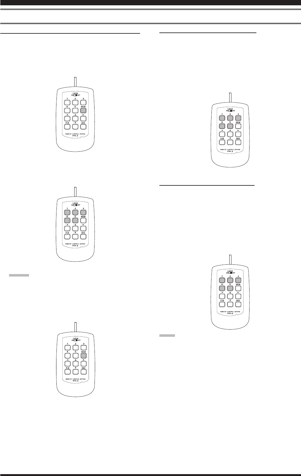
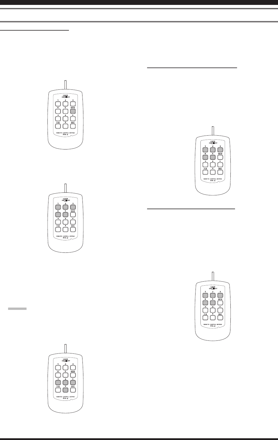
voice MeMory (SSb/AM/FM ModeS: requireS optionAl dvS-6 And Fh-2)
You may utilize the Voice Memory capability of the FT-991 for repetitive messages. The Voice Memory system
includes ve memories capable of storing up to 20 seconds of voice audio each. The maximum that any memory can
hold is 20 seconds.
Voice Memory Operation from the FH-2 Remote Control Keypad
You may also utilize the Voice Memory capability of the FT-991 from the optional FH-2 Remote Control Keypad,
which plugs into the rear panel’s REM/ALC jack.
TransMiTTer ConvenienCe feaTures
Recording Your Own Voice in Memory
1. Select the LSB, USB, AM, or FM mode using the
front panel MODE button.
2. Adjust
[MIC GAIN] on the LCD, as described on
page ##.
3. Press the [MEM] key on the FH-2. A blinking “REC”
icon will appear in the display.
4. Press any of the FH-2’s keys numbered [1] through
[5] to select that memory storage register.
Advice:
If you do not press the PTT key (see next step) with-
in ve seconds, the memory storage process will be
cancelled.
5. Press the microphone’s PTT switch momentarily.
The “REC” icon will glow steadily and recording
will begin.
6. Speak into the microphone in a normal voice level to
record the message (such as “CQ DX, CQ DX, this
is W 6 Delta X-Ray Charlie, W 6 Delta X-Ray Char-
lie, Over”). Remember that the time limit for record-
ing any message is 20 seconds.
Checking Your Recording
1. Be sure that [MOX] and [BK-IN] on the LCD dis-
played by pressing the F(M-LIST) button are “Off”.
2. Press the FH-2 [1] ~ [5] key (whichever one you just
recorded in). The “PLAY” icon will appear in the
display and you will hear the contents of the Voice
Memory you just recorded.
Advice:
You may adjust the playback level of the recording via
Menu item “009 RX OUT LEVEL”.
7. Press the FH-2 [MEM] key to terminate the message
storage process.

Page 57
FT-991 OperaTing Manual
TransMiTTer ConvenienCe feaTures
voice MeMory (SSb/AM/FM ModeS: requireS optionAl dvS-6 And Fh-2)
Transmitting the Recorded Message
1. Select the LSB, USB, AM, or FM mode using the
front panel MODE button.
2. Press the front panel F(M-LIST) button, then touch
[BK-IN] on the LCD.
3. Press the FH-2 [1] ~ [5] key (whichever one you
just recorded in). A “PLAY” icon will appear in the
display and the message will be transmitted.
Advice:
You may adjust the transmit (audio) level of the record-
ing via Menu item “010 TX OUT LEVEL”.

Page 58 FT-991 OperaTing Manual
vox (SSb/AM/FM ModeS: AutoMAtic tx/rx Switching uSing voice control)
Instead of using the microphone PTT switch or [MOX] displayed by pressing the F(M-LIST) button to activate the
transmitter, the VOX (Voice Operated TX/RX Control) system provides hands-free, automatic activation of the trans-
mitter, based on voice input into the microphone.
1. Press the F(M-LIST) button, then touch [VOX] on
the LCD to select “ON”. The “VOX” will appear in
the display.
2. Without pressing the PTT switch, speak into the
microphone in a normal voice level. When you start
speaking, the transmitter should be activated auto-
matically. When you nish speaking, the transceiver
should return to the receive mode (after a short de-
lay).
3. To cancel VOX and return to PTT operation, touch
[VOX] on the LCD once more. The “VOX” will
turn off, signifying that the VOX circuitry has been
turned off.
Advice:
The VOX Gain may be adjusted to prevent acciden-
tal transmitter activation in a noisy environment. To
adjust the VOX Gain:
1) Activate the VOX circuitry, if necessary.
2) Press the MENU(SETUP) button to engage the
Menu mode.
3) Rotate the MULTI knob to select Menu item “143
VOX GAIN”, then touch [SELECT] on the LCD.
4) While speaking into the microphone, rotate the
MULTI knob to the point where the transmitter
is quickly activated by your voice, without back-
ground noise causing the transmitter to activate.
5) When you satised with the setting, touch [EN-
TER] on the LCD to save the new setting.
6) Press the MENU(SETUP) button or touch
[BACK] on the LCD to exit to normal operation.
The “Hang-Time” of the VOX system (the transmit/
receive delay after the cessation of speech) may also
be adjusted via the Menu mode. The default delay is
500 msec. To set a different delay time:
1) Activate the VOX circuitry, if necessary.
2) Press the MENU(SETUP) button to engage the
Menu mode.
3) Rotate the MULTI knob to select Menu item “144
VOX DELAY”, then touch [SELECT] on the
LCD.
4) Rotate the MULTI knob while saying a brief syl-
lable like “Ah” and listening to the hang time for
the desired delay.
5) When you satised with the setting, touch [EN-
TER] on the LCD to save the new setting.
6) Press the MENU(SETUP) button or touch
[BACK] on the LCD to exit to normal operation.
TransMiTTer ConvenienCe feaTures
The Anti-Trip setting adjusts the level of negative re-
ceiver audio feedback to the microphone, to prevent
receiver audio from activating the transmitter (via
the microphone). This setting can also be adjusted
via Menu item “145 ANTI VOX GAIN”.
VOX operation may be engaged on either Voice
modes (SSB/AM/FM) or on AFSK-based Data
modes. Use Menu item “142 VOX SELECT” (the se-
lections are “MIC” and “DATA”).
MULTI Knob
MENU(SETUP) Button F(M-LIST) Button

Page 59
FT-991 OperaTing Manual
TransMiTTer ConvenienCe feaTures
Monitor (SSb/AM/FM ModeS)
You may listen to the quality of your transmitted signal using the Monitor feature.
1. Press the F(M-LIST) button, then touch [MONI] on
the LCD. The “MONI” will appear on the TFT dis-
play.
2. During transmission, rotate the MULTI knob to ad-
just the audio level in the Headphones or speaker.
Clockwise rotation of this knob will increase the vol-
ume level.
3. To switch the Monitor off again, touch [MONI] on
the LCD once more. Conrming that the Monitor is
now disengaged.
Advice:
Because the Monitor feature samples the transmit-
ter IF signal, it can be very useful for checking the
adjustment of the Speech Processor or Parametric
Equalizer on SSB, and for checking the general sig-
nal quality on AM and FM.
MULTI Knob
MENU(SETUP) Button F(M-LIST) Button
Page 60 FT-991 OperaTing Manual
TransMiTTer ConvenienCe feaTures
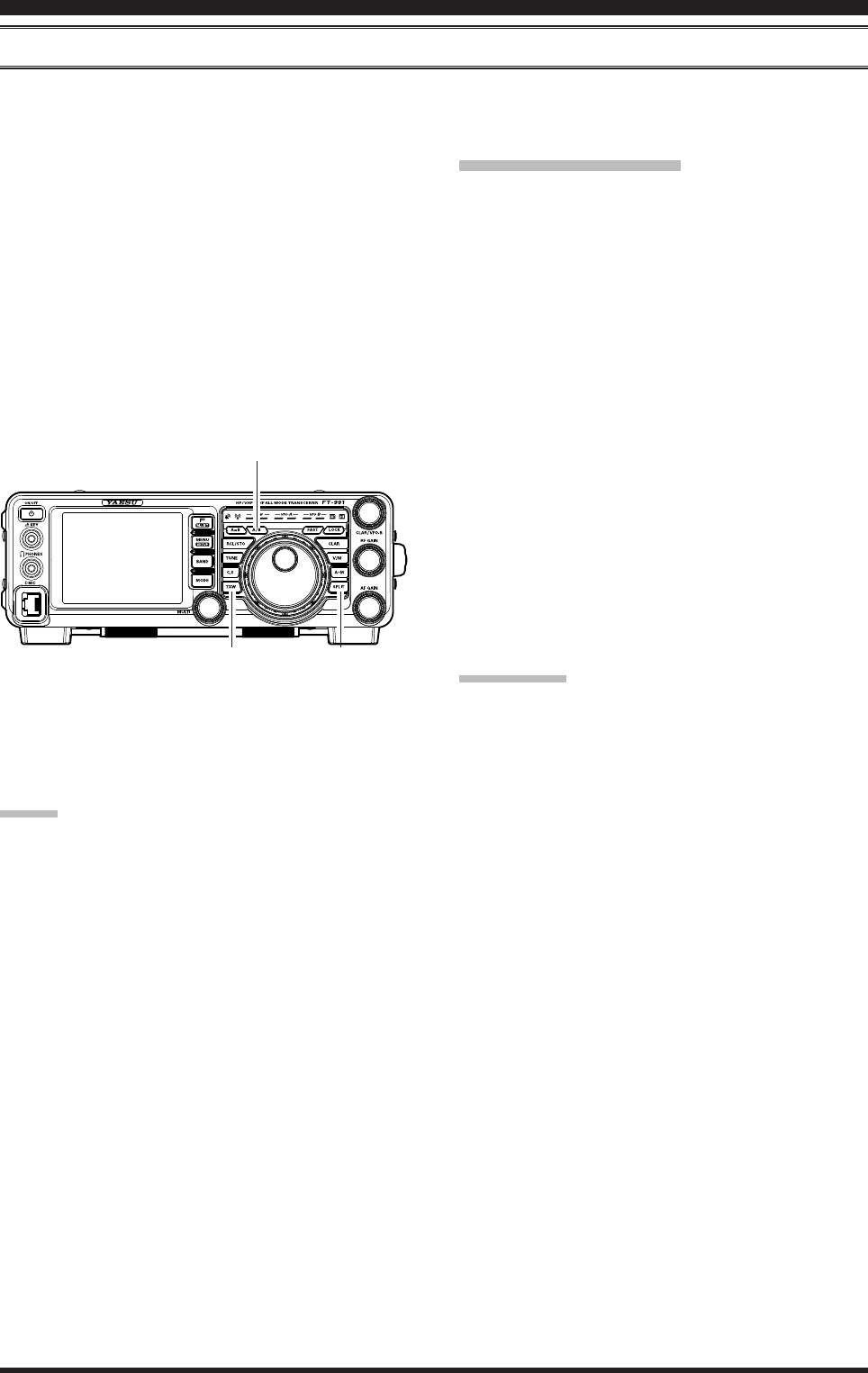
Split-Frequency operAtion
A powerful capability of the FT-991 is its exibility in Split Frequency operation using the VFO-A and VFO-B fre-
quency registers. This makes the FT-991 especially useful for high-level DX-peditions. The Split operation capability is
very advanced and easy to use.
1. Rotate the Main Tuning Dial knob to set the desired
RX frequency.
2. Press the A/B button, then rotate the Main Tuning
Dial knob to set the desired split TX frequency.
3. Press the A/B button, then press the SPLIT button.
The VFO-B frequency will appear in the TFT dis-
play and the LED indicators will look like as below:
VFO-A RX
Indicator: “ON”
(LED glows Green)
VFO-A TX Indicator: “OFF”
(LED Off)
VFO-B RX Indicator: “OFF”
(LED Off)
VFO-B TX
Indicator: “ON” (LED glows Red)
SPLIT Button
TXW Button
A/B Button
During Split operation, the VFO-A register will be used
for reception, while the VFO-B register will be used for
transmission. If you press the SPLIT button once more,
Split operation will be cancelled.
Advice:
During Split operation, pressing the A/ B button will
reverse the contents of the VFO-A and VFO-B. Press
the A/B button once more to return to the original
frequency alignment.
During Split operation you may listen to the TX fre-
quency temporarily while pressing the TXW button
located on the bottom left of the Main Tuning Dial
knob.
While pressing the TXW button during split opera-
tions, the frequency on the transmission side can be
changed.
It is possible to set different operating modes (for ex-
ample, LSB and USB) on the two VFOs used during
Split operation.
During Split operation it is also possible to set VFO-
A and VFO-B to different Amateur bands if you use
a multi band antenna.
Quick Split Operation
The Quick Split feature allows you to set a one-touch
offset of +5 kHz to be applied to your radio’s VFO-B
(transmit) frequency, compared to the VFO-A frequency.
1.
Start with regular transceiver operation on the VFO-A.
VFO-A RX
Indicator: “ON” (LED glows Green)
VFO-A TX
Indicator: “ON” (LED glows Red)
VFO-B RX Indicator: “OFF”
(LED Off)
VFO-B TX Indicator: “OFF”
(LED Off)
2. Press and hold in the SPLIT button for one second
to engage the Quick Split feature, and apply a fre-
quency 5 kHz above the VFO-A frequency to the
VFO-B frequency register.
The VFO conguration will then be:
VFO-A RX
Indicator: “ON” (LED glows Green)
VFO-A TX Indicator: “OFF”
(LED Off)
VFO-B RX Indicator: “OFF”
(LED Off)
VFO-B TX
Indicator: “ON” (LED glows Red)
3. Press and hold in the SPLIT switch for one second
to increment the Sub (VFO-B) frequency another +5
kHz.
quick pointS:
The operating mode applied to the VFO-B register
will be the same as that in use on the VFO-A regis-
ter.
The offset of VFO-B from VFO-A is programmed
via the Menu and is set to +5 kHz at the factory.
However, other offsets may be selected using the fol-
lowing procedure:
1. Press the MENU(SETUP) button to engage the
Menu mode.
2. Rotate the MULTI knob to select Menu item “034
QUICK SPLIT FREQ”.
3. Touch
[SELECT] on the LCD, then rotate the
MULT knob to select the desired offset. The avail-
able selections are –20kHz ~ +20kHz (factory de-
fault: +5 kHz).
4. Touch
[ENTER] button to save the new setting.
5. Press the MENU(SETUP) button or touch [BACK]
on the LCD to exit to normal operation.
Page 61
FT-991 OperaTing Manual
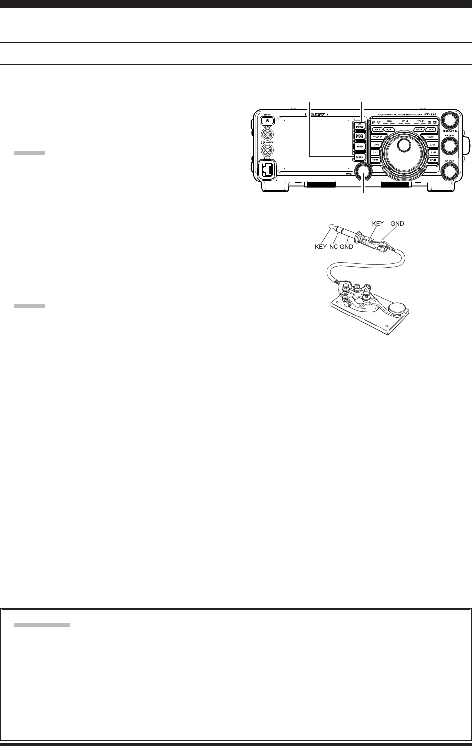
The powerful CW operating capabilities of the FT-991 permit operation using an electronic keyer paddle, a “straight
key”, or a computer-based keying device.
Setup For StrAight key (And StrAight key eMulAtion) operAtion
Before starting, connect your key line(s) to the front panel KEY jack. Be sure [BK-IN] displayed by pressing the F(M-
LIST) button is turned off for now.
1. Press the MODE button, then touch [CW-USB] on
the LCD. The “USB CW” icon will appear in the
display. The “MONI” icon will appear in the TFT
display; and the CW monitor is activated.
Advice:
If you press and hold the MODE button, you will
engage the “CW Reverse” mode, whereby the “op-
posite” sideband injection is used, compared to the
“normal” sideband. The “LSB CW” icon will ap-
pear in the display if you select CW Reverse.
2. Rotate the Main Tuning Dial knob to select the de-
sired operating frequency.
3. Press the F(M-LIST) button, then touch [BK-IN] on
the LCD to engage automatic activation of the trans-
mitter when you close the CW key. The “BK-IN”
icon will appear in the TFT display.
Advice:
When you close your CW key, the transmitter
will automatically be activated, and the CW car-
rier will be transmitted. When you release the
key, transmission will cease, and after a brief
delay, receive will be restored. The delay time is
user-programmable per the discussion on page
##.
As shipped from the factory, the FT-991 TX/RX
system for CW is configured for “Semi-break-
in” operation. However, using Menu item “057
CW BK-IN”, you may change this setup for full
break-in (QSK) operation, whereby the switch-
ing is quick enough to hear incoming signals in
the spaces between the dots and dashes of your
transmission. This may prove very useful during
contest and trafc handling operations.
4. Operation using your CW key may now proceed.
If you set [BK-IN] displayed by pressing the F(M-
LIST) button to Off, you may practice sending CW
with the sidetone only, without having the signal go
out over the air.
If you reduce power via [PROC] displayed by press-
ing the F(M-LIST) button, the ALC meter reading
will increase; this is normal and does not indicate
any problem whatsoever (because increased ALC
voltage is being used to lower the power).
terMinology:
Semi-break-in
This is a pseudo-”VOX” mode used on CW, whereby the closure of the CW key will engage the transmitter, and
release of the key will allow the receiver to recover after a short delay. No signals will be heard during the spaces
between dots and dashes (unless the sending speed is extremely slow).
Full break-in
Full break-in (also known as “Full QSK”) involves very fast switching between transmit and receive, incoming
signals may be heard between the dots and dashes as you send them. This allows you to hear a station that sud-
denly starts transmitting on your frequency, while you are in the midst of a transmission.
Cw Mode operaTion
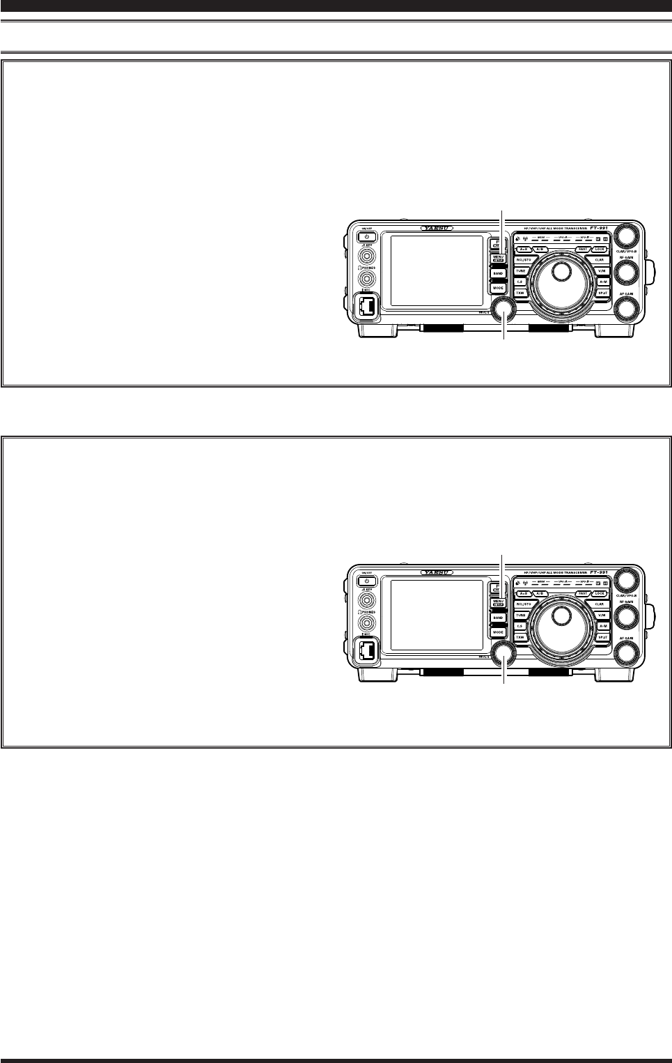
MULTI Knob
MODE Button F(M-LIST) Button
Page 62 FT-991 OperaTing Manual
Cw Mode operaTion
uSing the built-in electronic keyer
Connect the cable from your keyer paddle to the front panel KEY jack.
1. Press the MODE button, then touch [CW-USB] on
the LCD. The “USB CW” icon will appear in the
display. The “MONI” icon will appear in the TFT
display; and the CW monitor is activated.
Advice:
If you press the “CW” mode, you will engage the
“CW Reverse” mode, whereby the “opposite” side-
band injection is used, compared to the “normal”
sideband. The “LSB CW” icon will appear in the
display if you select CW Reverse.
2. Rotate the Main Tuning Dial knob to select the de-
sired operating frequency.
3. Press the F(M-LIST) button, then touch [KEYER]
on the LCD to select “ON”. The “KEYER” will ap-
pear in the display, conrming that the built-in Elec-
tronic Keyer is now active.
4. Touch
[SPEED] on the LCD repeatedly to set the
desired sending speed (4 ~ 60 WPM).
Advice:
The display will show the keying speed for 3 sec-
onds whenever [SPEED] on the LCD is touched.
When you press either the “Dot” or “Dash” side
of your paddle, the CW keying tone will auto-
matically be generated.
5. Touch
[BK-IN] on the LCD to engage automatic ac-
tivation of the transmitter when you press either the
“Dot” or “Dash” side of your paddle. The “BK-IN”
icon will appear in the TFT display.
6. CW operation utilizing your paddle may now com-
mence.
Advice:
When you utilize your keyer paddle, the transmit-
ter will automatically be activated, and the CW
characters (or a string of dots and dashes) will be
transmitted. When you release the keyer paddle con-
tacts, transmission will cease, and reception will be
restored after a brief delay. The delay time is user-
programmable, per the discussion on page ##.
If you set [BK-IN] displayed by pressing the F(M-
LIST) button to Off, you may practice sending CW
with the sidetone only, without having the signal go
out over the air.
If you reduce power via [PROC] displayed by press-
ing the F(M-LIST) button, the ALC meter reading
will increase; this is normal and does not indicate
any problem whatsoever (because increased ALC
voltage is being used to lower the power).
MULTI Knob
MODE Button F(M-LIST) Button
Page 63
FT-991 OperaTing Manual
Full Break-in (QSK) Operation
As shipped from the factory, the FT-991 TX/RX system for CW is congured for “Semi-break-in” operation.
However, this setup may be changed to full break-in (QSK) operation using Menu item “057 CW BK-IN”. With
full break-in QSK, the TX/RX switching is quick enough to hear incoming signals in the spaces between the dots
and dashes of your transmission.
1. Press the MENU(SETUP) button to engage the
Menu.
2. Rotate the MULTI knob to select Menu item “057
CW BK-IN”.
3. Press the [SELECT] button, then rotate the
MULTI knob to set this Menu item to “FULL”.
4. When your adjustments are complete, touch [EN-
TER] on the LCD to save the new setting.
5. Press the MENU(SETUP) button or touch
[BACK] on the LCD to exit to normal operation.
A number of interesting and useful features are available during Electronic Keyer operation.
uSing the built-in electronic keyer
Cw Mode operaTion
Setting the Keyer Weight (Dot/Dash) Ratio
This Menu item may be used to adjust the dot/dash ratio for the built-in Electronic Keyer. The default weighting
is 3:1 (a dash is three times longer than a dot).
1. Press the MENU(SETUP) button to engage the
Menu.
2. Rotate the MULTI knob to select Menu item “01
3 CW WEIGHT”.
3. Press the [SELECT] button, then rotate the
MULTI knob to set the weight to the desired val-
ue. The available adjustment range is a Dot/Dash
ratio of 2.5 ~ 4.5 (default value: 3.0).
4. When your adjustments are complete, touch [EN-
TER] on the LCD to save the new setting.
5. Press the MENU(SETUP) button or touch
[BACK] on the LCD to exit to normal operation.
MULTI Knob
MULTI Knob
MENU(SETUP) Button
MENU(SETUP) Button
Page 64 FT-991 OperaTing Manual
Cw Mode operaTion
Selecting the Keyer Operating Mode
The conguration of the Electronic Keyer may be customized independently for the front panel KEY jack of the
FT-991. This permits utilization of Automatic Character Spacing (ACS), if desired. This permits the use of an
electronic keyer via the front jack and a straight key or computer-driven keying line via the rear panel jack.
1. Press the MENU(SETUP) button to engage the
Menu.
2. Rotate the MULTI knob to select Menu item “011
KEYER TYPE”.
3. Press the [SELECT] button, then rotate the
MULTI knob to set the keyer to the desired mode.
The available selections are:
OFF: The built-in Electronic Keyer is turned
off (“straight key” mode).
BUG: Dots will be generated automatically
by the keyer, but dashes must be sent
manually.
ELEKEY: Both dots and dashes will be generated
automatically when using a paddle.
ACS: Same as “ELEKEY” except that the spac-
ing between characters is precisely set
by the keyer to be the same length as a
dash (three dots in length)
4. When your adjustments are complete, touch [EN-
TER] on the LCD to save the new setting.
5. Press the MENU(SETUP) button or touch
[BACK] on the LCD to exit to normal operation.
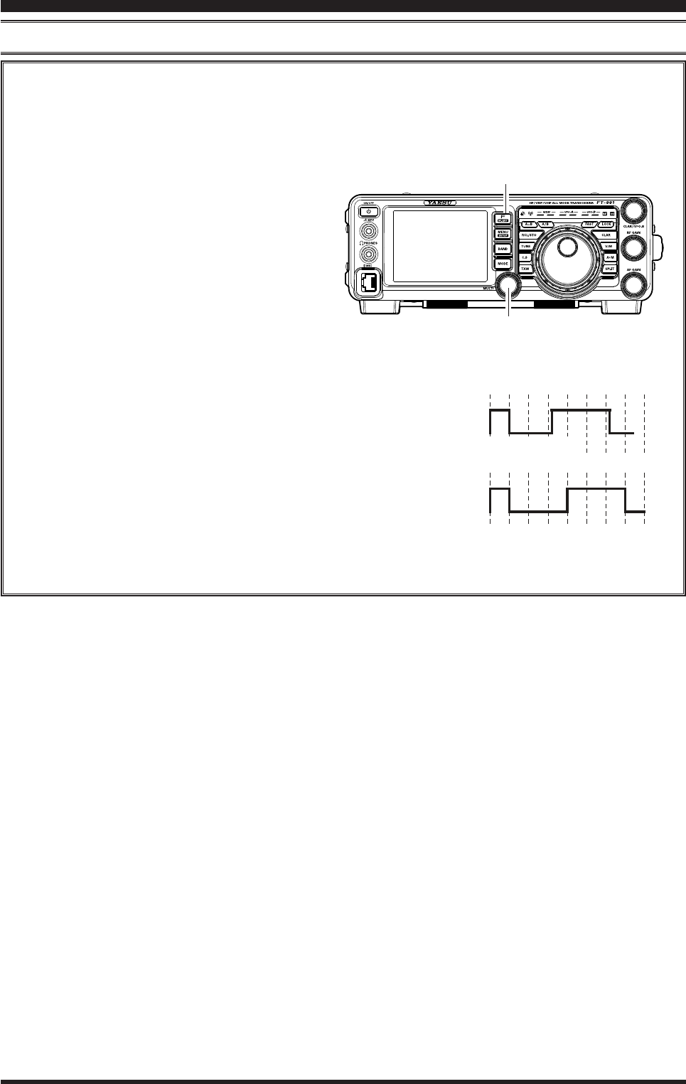
uSing the built-in electronic keyer
Morse
"E" & "T"
Morse
"E" & "T"
ACS
OFF
スペース
ACS
ON
Inter-character
Spacing too short
MULTI Knob
MENU(SETUP) Button
Page 65
FT-991 OperaTing Manual
cw Spotting (zero-beAting)
“Spotting” (zeroing in on another CW station) is a handy technique to ensure you and the other station are precisely on
the same frequency.
The Tuning Offset Indicator in the display may also be moved so you can adjust your receiver frequency to center the
incoming station on the pitch corresponding to that of your transmitted signal.
Using the Auto Zeroing System
(Only when the optional FFT unit is installed)
Press the F(M-LIST) button, then touch [ZIN] on the
LCD to adjust the receiving frequency to the zero-in au-
tomatically while receiving the CW signal.
Using the SPOT System
Press the F(M-LIST) button, then touch [SPOT] on the
LCD. Touch [MONI] on the LCD, the Spot tone will be
heard through your speaker. This tone corresponds to the
pitch of your transmitted signal. If you adjust the receiv-
er frequency until the pitch of the received CW signal
matches that of the Spot tone, your transmitted signal
will be precisely matched to that of the other station.
Touch [SPOT] on the LCD again to turn the Spot tone
off.
Advice:
In a tough DX pile-up, you may actually want to
use the SPOT system to nd a “gap” in the spread
of calling stations, instead of zeroing in precisely
on the last station being worked by the DX station.
From the DX side, if a dozen or more operators (also
using Yaesu’s SPOT system) all call precisely on the
same frequency, their dots and dashes merge into a
single, long tone that the DX station cannot decipher.
In such situations, calling slightly higher or lower in
frequency may get your call through.
quick pointS:
The displayed frequency on CW normally reflects
the “zero beat” frequency of your offset carrier. That
is, if you were to listen on USB on 14.100.00 MHz
to a signal with a 700 Hz offset, the “zero beat” fre-
quency of that CW carrier would be 14.100.70 MHz;
the latter frequency is what the FT-991 displays, by
default. However, you can change the display to be
identical to what you would see on SSB by using
Menu item “060 CW FREQ DISPLAY” and setting
it to “DIRECT FREQ” instead of the default “PITCH
OFFSET” setting.
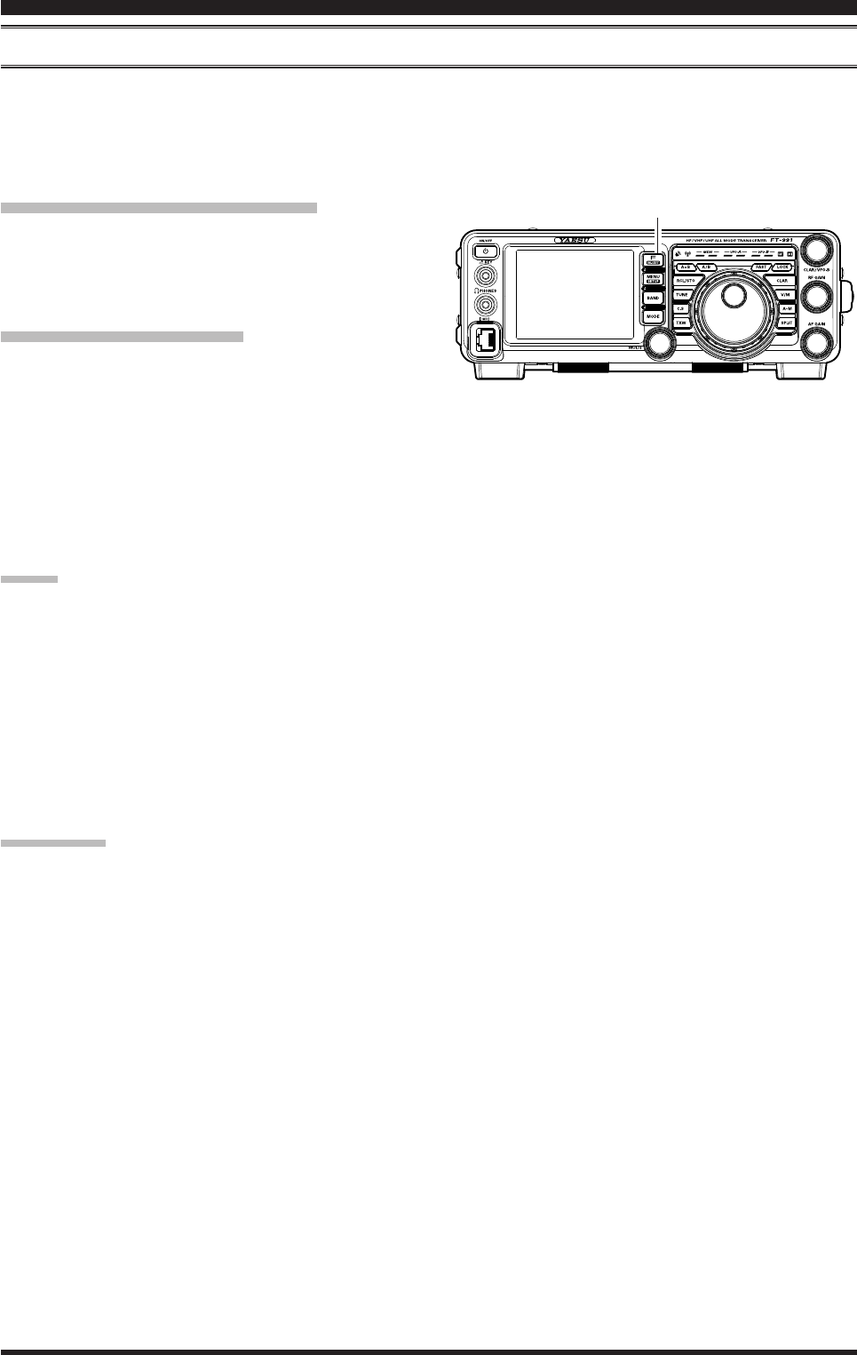
Cw ConvenienCe feaTures
F(M-LIST) Button
Page 66 FT-991 OperaTing Manual
cw delAy tiMe Setting
During semi-break-in (not QSK) operation, the hang time of the transmitter, after you have nished sending, may be ad-
justed to a comfortable value consistent with your sending speed. This is the functional equivalent of the “VOX Delay”
adjustment used on voice modes, and the delay may be varied anywhere between 30 msec and 3 seconds via Menu item
“064 CW BK-IN DELAY”.
1. Press the F(M-LIST) button, then touch [BK-IN]
on the LCD to enable CW transmission (Menu item
“057 CW BK-IN” must be set to “SEMI”).
2. Press the MENU(SETUP) button to enter the Menu
mode.
3. Rotate the MULTI knob to select Menu item “058
CW BK-IN DELAY”, then touch [SELECT] on the
LCD.
4. Start sending and rotate the MULTI knob to adjust
the hang time, as you prefer for comfortable opera-
tion.
5. When your adjustments are complete, touch [EN-
TER] on the LCD to save the new setting.
6. Press the MENU(SETUP) button or touch [BACK]
on the LCD to exit to normal operation.
Cw ConvenienCe feaTures
MULTI Knob
MENU(SETUP) Button F(M-LIST) Button
Page 67
FT-991 OperaTing Manual
Cw ConvenienCe feaTures
MULTI Knob
MULTI Knob
MENU(SETUP) Button
MENU(SETUP) Button
conteSt MeMory keyer (uSing the optionAl Fh-2 reMote control keypAd)
You may also utilize the CW message capability of the FT-991 from the optional FH-2 Remote Control Keypad, which
plugs into the rear panel REM/ALC jack.
Message Memory
Five memory channels capable of retaining 50 characters each are provided (using the PARIS standard for characters
and word length).
Example: CQ CQ CQ DE W6DXC K (19 characters)
-- •-- • -- -- •-- -- •-- • -- -- •-- --•-- • -- -- •-- --•• • •-- -- -- •••• -- •• -- ••-- --•-- • -- •--
(C) (Q) (C) (Q) (C) (Q) (D) (E) (W) (6) (D) (X) (C) (K)
Storing A MeSSAge into MeMory
1. Press the MENU(SETUP) button to enter the Menu
mode.
2. Rotate the MULTI knob to select the CW Memory
Register into which you wish to store the message;
for now, we are just setting the message entry tech-
nique to (Keyer entry).
017 CW MEMORY 1
018 CW MEMORY 2
019 CW MEMORY 3
020 CW MEMORY 4
021 CW MEMORY 5
3. Touch
[SELECT] on the LCD, then rotate the
MULTI knob to set the selected CW Memory Reg-
ister to “MESSAGE”. If you want to use your keyer
paddle for message entry on all memories, set all ve
Menu items (#017 ~ 021) to “MESSAGE”.
4. Touch
[ENTER] on the LCD to save the new set-
ting.
5. Press the MENU(SETUP) button or touch [BACK]
on the LCD to exit to normal operation.
Contest Number Programming
Use this process if you are starting a contest, or if you somehow get out of sync with the proper number in the
middle of a contest.
1. Press the MENU(SETUP) button to enter the
Menu mode.
2. Rotate the MULTI knob to select Menu item “016
CONTEST NUMBER”. The current contest num-
ber appears on the TFT display.
3. Touch
[SELECT] on the LCD, then rotate the
MULTI knob to set the Contest Number to the
desired value.
Advice:
Touch
[BACK] on the LCD to cancel the setting.
4. Touch
[ENTER] on the LCD to save the new set-
ting.
terMinology:
PARIS Word Length: By convention among CW and
Amateur operators (utilized by ARRL and others), the
length of one “word” of CW is dened as the length of
the Morse Code characters spelling the word “PARIS”.
This character (dot/dash/space) length is used for the
specic denition of code speed in “words per minute”.
5. Press the MENU(SETUP) button or touch
[BACK] on the LCD to exit to normal opera-
tion.
Page 68 FT-991 OperaTing Manual
checking the cw MeMory contentS
1. Be sure that Break-in is still turned “Off” by [BK-IN]
on the LCD.
2. Touch [MONI] on the LCD to enable the CW moni-
tor.
3. Press the FH-2 [1] ~ [5] key, whichever memory
you just recorded in. You will hear the results in the
sidetone monitor, but no RF energy will be transmit-
ted.
on-the-Air cw MeSSAge plAybAck
1. Touch
[BK-IN] on the LCD to enable transmission.
Either Full- or Semi-break-in will be engaged, de-
pending on the setting of Menu item “057 CW BK-
IN”.
2. Press the FH-2 [1] ~ [5] key, depending on which
CW Memory Register message you wish to transmit.
The programmed message will be transmitted on the
air.
note:
If you subsequently decide to use the “Text Memory”
technique for memory storage, please note that a mes-
sage stored using keyer paddle input will not be trans-
ferred over when you select “Text Memory technique”
on a particular memory register (the Menu Mode Setting
is set to “TEXT”).
conteSt MeMory keyer (uSing the optionAl Fh-2 reMote control keypAd)
MeSSAge MeMory progrAMMing (uSing your pAddle)
1. Set the operating mode to CW.
2. Set
[BK-IN] on the LCD to “Off”.
3. Turn the internal Electronic Keyer “On”.
4. Press the [MEM] key on the FH-2. A blinking “REC”
icon will appear in the display.
5. Press any of the FH-2 keys numbered [1] through [5]
to begin the memory storage process, and the “REC”
icon will glow steadily.
6. Send the desired message using your keyer paddle.
Advice:
If you do not start keying within ten seconds, the
memory storage process will be cancelled.
7. Press the [MEM] key on the FH-2 once more at the
end of your message. Up to 50 characters may be
stored in each of the ve memories.
Cw ConvenienCe feaTures
Page 69
FT-991 OperaTing Manual
Cw ConvenienCe feaTures
TEXT Memory
The ve channels of CW message memory (up to 50 characters each) may also be programmed using a text-entry tech-
nique. This technique is somewhat slower than when you send the message directly from your keyer paddle, but accu-
racy of character spacing is ensured. Be sure to enter the character “}” at the end of texts.
Example 1: CQ CQ CQ DE W6DXC K} (20 characters)
The sequential Contest Number (“Count up”) feature is another powerful feature of the CW Memory Keyer.
Example 2: 599 10 200 # K} (15 characters)
text MeMory StorAge
1. Press and hold in the MENU(SETUP) button for
one second to enter the Menu mode.
2. Rotate the MULTI knob to select the CW Memory
Register into which you wish to store the message;
we are now setting the message entry technique to
(Text entry).
017 CW MEMORY 1
018 CW MEMORY 2
019 CW MEMORY 3
020 CW MEMORY 4
021 CW MEMORY 5
Advice:
The following texts are programmed to the MEM-
ORY 4 and MEMORY 5 in factory default.
MEMORY 4: DE FT-991 K}
MEMORY 5: R 5NN K}
3. Touch
[SELECT] on the LCD, then rotate the
MULTI knob to set the selected CW Memory Regis-
ter to “TEXT”. If you want to use text message entry
on all memories, set all five Menu items (#017 ~
021) to “TEXT”.
4. Touch
[ENTER] on the LCD to save the new set-
ting.
5. Press the MENU(SETUP) button or touch [BACK]
on the LCD to exit to normal operation.
conteSt MeMory keyer (uSing the optionAl Fh-2 reMote control keypAd)
CW CODE
SN
AF
SX
KA
TEXT
+
,
-
.
/
CW CODE
AS
WG
KN
KK
CW CODE
AR
MIM
DU
AAA
DN
CW CODE
OS
KR
BT
CW CODE
IMI
@
AL
CW CODE
IQ
TEXT
!
”
#
$
%
TEXT
:
;
<
=
>
TEXT
?
@
[
¥(\)
}
TEXT
^
_
}
TEXT
&
´
(
)
*
MULTI Knob
MENU(SETUP) Button
Page 70 FT-991 OperaTing Manual
conteSt MeMory keyer (uSing the optionAl Fh-2 reMote control keypAd)
text MeSSAge progrAMMing
1. Press the MODE button to set the operating mode to
CW.
2. Be sure that Break-in is “Off” with [BK-IN] on the
LCD, if necessary.
3. Press the FH-2 [MEM] key. A blinking “REC” icon
will appear in the display.
4. Press an FH-2 [1] ~ [5] key to select the desired CW
Memory Register into which you wish to program
the text, the blinking “REC” icon will disappear.
5. Use the FH-2 [t] and [] keys to set the cursor
position and use the FH-2’s [p] and [q] keys to
choose the letter/number to be programmed in each
slot of the memory. In the case of the second ex-
ample on the previous page the “#” character desig-
nates the slot where the Contest Number will appear.
Advice:
You may also use the Main Tuning Dial knob and the
MULTI knobs to program the message characters.
6. When the message is complete, add the “}” character
at the end to signify the termination of the message.
7. Press and hold in the FH-2 [MEM] key for one sec-
ond to exit, once all characters (including “}”) have
been programmed.
checking the cw MeMory contentS
1. Be sure that Break-in is still turned “Off” with [BK-
IN] on the LCD.
2. Touch [MONI] on the LCD to enable the CW moni-
tor.
3. Press an FH-2 [1] ~ [5] key, whichever memory you
just recorded in. You will hear the results in the sid-
etone, but no RF energy will be transmitted.
on-the-Air cw MeSSAge plAybAck
1. Touch [BK-IN] on the LCD to enable transmission.
Either Full-break-in or Semi-break-in will be en-
gaged, depending on the setting of Menu item “063
CW BK-IN”.
2. Press an FH-2 [1] ~ [5] key, depending on which
CW Memory Register message you wish to transmit.
The programmed message will be transmitted on the
air.
Cw ConvenienCe feaTures

Page 71
FT-991 OperaTing Manual
Cw ConvenienCe feaTures
note:
If you subsequently decide to use the “Message Memo-
ry” technique for memory storage, please note that the
contents of a message stored using text input will not be
transferred over when you set entry to “Message Memo-
ry technique” on a particular memory register (the Menu
Mode Setting is set to “MESSAGE”).
Decrementing the Contest Number
Use this process if the current contest number
gets slightly ahead of the actual number you
want to send (in case of a duplicate QSO, for ex-
ample).
Press the FH-2 [DEC] key momentarily. The
current Contest Number will be reduced by one.
Press of the FH-2 [DEC] key as many times as
necessary to reach the desired number. If you go
too far, use the “Contest Number Programming”
technique described previously.
conteSt MeMory keyer (uSing the optionAl Fh-2 reMote control keypAd)
Transmitting in the Beacon Mode
In “Beacon” mode, it is possible to repeatedly
transmit any message programmed, either via
paddle input, or via the “Text” input method. The
time delay between message repeats may be set
anywhere between 1 and 690 seconds (1 ~ 240
sec (1 sec/step) or 270 ~ 690 sec (30 sec/step))
via Menu item “014 BEACON TIME” If you do
not wish the message to repeat in a “Beacon”
mode, please set this Menu item to “OFF”.
To transmit the message:
1. Touch [BK-IN] on the LCD to enable trans-
mission. Either Full-break-in or Semi-break-
in will be engaged, depending on the setting
of Menu item “057 CW BK-IN”.
2. Press an FH-2 [1] ~ [5] key. Repetitive trans-
mission of the Beacon message will begin.

Page 72 FT-991 OperaTing Manual
FM Mode operation
Basic OperatiOn
1. Press the MODE button, then touch the correspond-
ing key on the LCD to select the FM operating
mode. The “FM” icon appears in the display.
2. Rotate the Main Tuning Dial knob to select the de-
sired operating frequency. Pressing the microphone
UP or DWN button will cause frequency change in 5
kHz steps.
3. Press the microphone PTT switch to transmit. Speak
into the microphone in a normal voice level. Release
the PTT switch to return to receive.
4. Adjustment of the microphone gain may be accom-
plished in two ways. At the factory, a default level
has been programmed that should be satisfactory for
most situations. However, using Menu item “077
FM MIC GAIN”, you may set a different xed value,
or choose the “MCVR” option, which then lets you
use [MIC GAIN] on the LCD to set the microphone
gain in the FM mode.
advice:
The Transmit Monitor is another helpful way to
verify proper adjustment of the FM MIC Gain. With
[MONI] displayed by pressing the F(M-LIST) but-
ton, you will be able to hear the differences in devia-
tion as you make adjustments.
FM is only used in the 28 MHz, 50 MHz, 144 MHz,
and 430 MHz Amateur bands covered by the FT-
991. Please do not use FM on any other bands.
MODE Button
F(M-LIST) Button
Page 73
FT-991 OperaTing Manual
repeAter operAtion
The FT-991 may be utilized on 29 MHz, 50 MHz, 144 MHz, and 430 MHz repeaters.
1. Rotate the Main Tuning Dial knob to the output fre-
quency (downlink) from the repeater.
2. If CTCSS Tone operation is desired/needed, press
the F(M-LIST) button, then touch [TONE] on the
LCD to engage the CTCSS mode.
3. Touch [TONE] on the LCD repeatedly to select the
desired CTCSS mode. If you just need to send the
uplink encoding tone, select “ENC.” For encode/de-
code operation, choose “T.SQL” instead. The avail-
able choices are
“OFF” “ENC (Tone Encoder)”
“T.SQL (Tone Squelch)” “OFF”
4. Rotate the MULTI knob to select the desired CTCSS
Tone to be used. A total of 50 standard CTCSS tones
are provided (see the CTCSS Tone Chart).
5. Press the F(M-LIST) button, then touch [RPT] on
the LCD to select the desired repeater shift direction.
The selections are:
“SIMP” “+” “–” “SIMP”
where “SIMP” represents “Simplex” operation (not
used on a repeater).
6. Press and hold the microphone PTT switch to begin
transmission. You will observe that the frequency
has shifted to correspond to the programming you set
up in the previous steps, and a “t” notation will ap-
pear on the “10 Hz” frequency digit while transmit-
ting. Speak into the microphone in a normal voice
level. Release the PTT switch to return to the receive
mode.
Advice:
The conventional repeater shift used on 29 MHz is
100 kHz, while on the 50 MHz band the shift may
vary between 500 kHz and 1.7 MHz (or more). To
program the proper repeater shift, use Menu items
“083 RPT SHIFT (28MHz)” (28 MHz), “084 RPT
SHIFT (50MHz)” (50 MHz), “085 RPT SHIFT
(144MHz)” (144 MHz), and “086 RPT SHIFT
(430MHz)” (430 MHz) as appropriate.
ctcSS tone Frequency (Hz)
67.0 69.3 71.9 74.4 77.0 79.7 82.5 85.4
88.5 91.5 94.8 97.4 100.0 103.5 107.2 110.9
114.8 118.8 123.0 127.3 131.8 136.5 141.3 146.2
151.4 156.7 159.8 162.2 165.5 167.9 171.3 173.8
177.3 179.9 183.5 186.2 189.9 192.8 196.6 199.5
203.5 206.5 210.7 218.1 225.7 229.1 233.6 241.8
250.3 251.4 - - - - - -
fM Mode operaTion
MULTI Knob
MENU(SETUP) Button F(M-LIST) Button

Page 74 FT-991 OperaTing Manual
fM Mode operaTion
tone Squelch operAtion
You may also use “Tone Squelch” whereby your receiver will be kept silent until an incoming signal modulated with a
matching CTCSS tone is received. The receiver squelch will then open in response to the reception of the required tone.
1. Rotate the Main tuning Dial to the output frequency
(downlink) from the repeater.
2. If CTCSS Tone operation is desired/needed, press
the F(M-LIST) button, then touch [TONE] on the
LCD to engage the CTCSS mode.
3. Touch [TONE] on the LCD repeatedly to choose
“T.SQL” from the available choices of
“OFF” “ENC (Tone Encoder)”
“T.SQL (Tone Squelch)” “OFF”
4. Rotate the MULTI knob to select the desired CTCSS
Tone to be used. Fifty standard CTCSS tones are
provided (see the CTCSS Tone Chart).
5. A “d” notation on the “1 Hz” frequency digit in
the display will indicate that the Tone Decoder is
engaged. A “t” notation on the “1 Hz” frequency
digit while transmitting will indicate that the Tone
Squelch is engaged.
MULTI Knob
MENU(SETUP) Button F(M-LIST) Button
Page 75FT-991 OperaTing Manual
convenient MeMory FunctionS
The FT-991 contains ninety-nine regular memories, labeled “01” through “99”, nine special programmed limit mem-
ory pairs, labeled “P-1L/P-1U” through “P-9L/P-9U”, and ve QMB (Quick Memory Bank) memories, labeled “C-1”
through “C-5”. Each stores various settings, in addition to the VFO-A frequency and mode (See below). By default, the
99 regular memories are contained in one group; however, they can be arranged in up to six separate groups, if desired.
quick point:
The FT-991 memory channels store the following
data (not just the operating frequency):
VFO-A Frequency
VFO-A Mode
Clarier status and its Offset Frequency
ANT status
IPO status
Roong lter status and its Bandwidth
Attenuator status
Noise Blanker status
IF SHIFT and WIDTH status
CONTOUR status and its Peak Frequency
DSP Noise Reduction (DNR) status and its
Reduction algorithm selection.
DSP Notch lter (NOTCH) status
NAR bandwidth status
DSP Auto Notch lter (DNF) status
Repeater Shift Direction
MeMorY operaTion
qMb MeMory chAnnel
regulAr MeMory chAnnelS pMS MeMory chAnnelS
C-1 C-2 C-3 C-4 C-5
01
97 P-7L/7U
P-6L/6U
P-5L/5U
P-4L/4U
02
98 P-8L/8U
03
99 P-9L/9U
P-1L/1U
P-2L/2U
P-3L/3U
qMb (quick MeMory bAnk)
The Quick Memory Bank consists of ve memories (labeled “Q-1” through “Q-5”) independent from the regular and
PMS memories. These can quickly store operating parameters for later recall.
RCL/STO Button
QMB Channel Storage
1. Tune to the desired frequency on the VFO-A.
2. Press the RCL/STO button. The “beep” will conrm
that the VFO-A contents have been written to the
currently available QMB memory.
If you repeatedly press the RCL/STO button, the QMB
memories will be written in the following order:
Q-2 Q-3 Q-4 Q-5 Q-1.
Once all ve QMB memories have data on them, previ-
ous data (starting with channel Q-1) will be over-written
on a rst-in, rst-out basis.
QMB Channel Recall
1. Press the RCL/STO button. The current QMB chan-
nel data will be shown on the frequency display area.
The “QMB” icon will also appear and the Memory
Mode indicators in the LED indicators area will il-
luminate.
2. Repeatedly pressing the RCL/STO button will tog-
gle you through the QMB channels:
Q-2 Q-3 Q-4 Q-5 Q-1.
3. Press the V/M button to return to the VFO or Memo-
ry mode.
Advice:
Rotating the Main Tuning Dial knob, or changing the
operating mode, will place the transceiver in the “Mem-
ory Tune” mode, which is a temporary “pseudo-VFO”
method of tuning off of a stored memory channel. If you
do not over-write the contents of the current memory
channel, the original contents will not be disturbed by
the initiation of Memory Tune operation.
Page 76 FT-991 OperaTing Manual
StAndArd MeMory operAtion
The Standard Memory of the FT-991 allows storage and recall of up to 99 memories, each storing frequency, mode,
and a wide variety of status information, detailed previously. Memories may be grouped into as many as six Memory
Groups, and additionally you get nine pairs of band-limit (PMS) memories along with ve QMB (Quick Memory Bank)
memories.
Memory Storage
1. Set VFO-A up with the frequency, mode, and status,
the way you want to have it stored.
2. Press the A
M button momentarily; the current
channel number will start blinking in the display and
the “MCK” notation will appear.
3. Rotate the MULTI knob to select the memory chan-
nel that you wish to store the data on.
4. Press and hold in the A
M button for one second to
store the frequency and other data into the selected
memory channel. A double beep will confirm that
you have held the A
M button in long enough.
Memory Channel Recall
1. Press the V/M button, if necessary, to enter the
“Memory mode”.
2. Press the F(M-LIST) button, then touch [MCH] on
the LCD. A memory channel number and the “MCH”
notation will appear in the display.
3. After touching [MCH] on the LCD, you may rotate
the MULTI knob to select the desired memory chan-
nel.
Advice:
To work within a particular Memory Group, press the
F(M-LIST) button, then touch [GRP] on the LCD.
Rotate the MULTI knob to select the desired Memory
Group, then touch [ENTER] on the LCD (the “MCH”
notation will appear instead of the “GRP”); you may
now choose the memory channel within the selected
Memory Group.
F(M-LIST) Button
V/M ButtonMULTI Knob
A
M ButtonMULTI Knob
MeMorY operaTion
Page 77FT-991 OperaTing Manual
MeMorY operaTion
StAndArd MeMory operAtion
Labeling Memories
You may wish to append an Alphanumeric “Tag” (label) to a memory or memories, to aid in recollection of the chan-
nel’s use (such as a club name, etc.). To do this:
1. Press the V/M button, if necessary, to enter the
“Memory Mode”.
2. Press and hold in the F(M-LIST) button.
The data stored in the currently selected memory
channel will be displayed on the TFT.
3. Rotate the MULTI knob to recall the memory chan-
nel that you wish to append a label.
4. Touch
[TAG] on the LCD.
A blinking cursor will appear on the rst digit.
5. Touch a key on the LCD to enter the letters, num-
bers, or symbols of the desired label.
6. Repeat step 5 to program the remaining letters, num-
bers, or symbols of the desired label. 18 characters
may be used in the creation of a label.
Use
[] and [] on the LCD to set the cursor posi-
tion and [t] on the LCD to erase a letter at the left
of the cursor.
7. When you have completed the creation of the label,
touch [ENT] on the LCD.
8. Press the F(M-LIST) button to save the new setting
and return to normal operation.
Checking a Memory Channel Status
Before programming a channel into memory, you can check the current contents of that channel without the danger of
over-writing the channel accidentally.
1. Press the A
M button momentarily.
The data stored in the currently selected memory
channel will be displayed on the TFT. However,
since you are only checking the contents of the
memory channel, your radio will not have moved to
the memory channel frequency.
2. Rotate the MULTI knob to select a different memory
channel. To exit from the Memory Check mode,
press the A
M button momentarily once more.
Advice:
While the Memory Check function is engaged, the
memory channel number will blink in the display.
While operating in the VFO mode, using Memory
Check, you may store the current VFO frequency
into the selected memory by pressing and holding
in the A
M button for one second (until the double
beep). Conversely, if you wish to write the contents
of the current memory into the VFO-A register, press
the V/M button.
V/M Button
V/M ButtonMULTI Knob
A
M ButtonMULTI Knob

Page 78 FT-991 OperaTing Manual
MeMorY operaTion
StAndArd MeMory operAtion
MULTI Knob
F(M-LIST) Button
Erasing Memory Channel Data
1. Press and hold in the F(M-LIST) button.
2. Rotate the MULTI knob to select the memory chan-
nel that you would like to erase.
3. Touch
[ERASE] on the LCD.
Advice:
The
FT-991 can not erase the memory channels “01”
(and “501” through “510”: U.S. version).
If you make a mistake and wish to restore the memo-
ry’s contents, just repeat steps (1) through (3) above.

Page 79FT-991 OperaTing Manual
MeMorY operaTion
StAndArd MeMory operAtion
Memory Tune Operation
You may freely tune off from any memory channel in a “Memory Tune” mode, this is similar to VFO operation. So long
as you do not over-write the contents of the current memory, Memory Tune operation will not alter the contents of the
memory channel.
1. Press the V/M button to recall any memory channel.
2. Press the F(M-LIST) button, then touch [MCH] on
the LCD.
3. Rotate the MULTI knob to select the memory chan-
nel.
4. Rotate the Main Tuning Dial knob; you will now ob-
serve that the memory channel frequency is chang-
ing.
Advice:
During Memory Tune operation, you may change
operating modes, and engage the offset Clarier,
if desired.
5. Press the V/M button momentarily to return to the
originally memorized frequency of the current mem-
ory channel. One more press of the V/M button will
return to VFO operation.
note:
Computer software programs utilizing the CAT system
interface port may presume that the transceiver is oper-
ating in the VFO mode, for certain features like “band
mapping” and/or frequency logging, because the “Mem-
ory Tune” mode so closely resembles the VFO mode.
Be sure that you have the FT-991 operating in a control
mode compatible with your software’s requirements.
Use the VFO mode if you’re not sure.
V/M ButtonMULTI Knob
F(M-LIST) Button
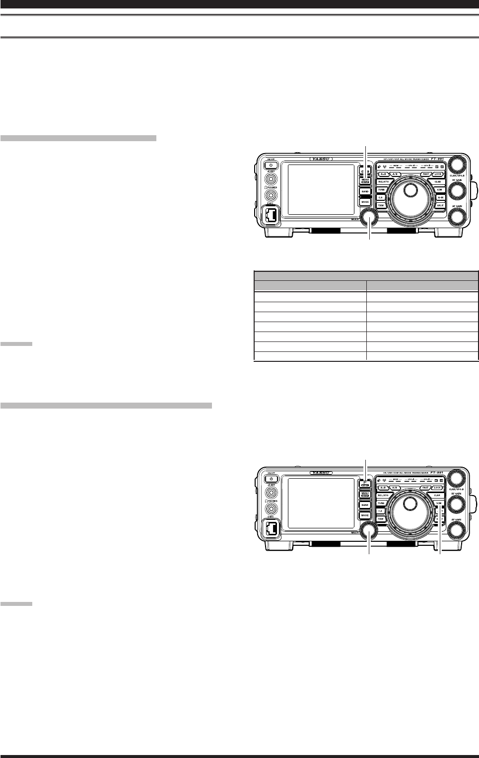
Page 80 FT-991 OperaTing Manual
MeMorY operaTion
MeMory groupS
Memory channels may be arranged into as many as six convenient groups, for easy identication and selection. For ex-
ample, you might want to designate memory groups for AM BC stations, short-wave broadcast stations, contest frequen-
cies, repeater frequencies and PMS limits, or any other groupings you like.
Each memory group is capable of holding up to 20 memory channels (except Memory Group 01: it is 19 memory chan-
nels, and the Group size is xed). When a memory channel is grouped, the channel numbers change to correspond to the
chart below:
Memory Group Assignment
1. Press the MENU(SETUP) button to enter the Menu
mode.
2. Rotate the MULTI knob to select Menu item “033
MEM GROUP”.
3. Touch
[SELECT] on the LCD, then rotate the
MULTI knob to set this Menu item to “ENABLE” (the
default setting is “DISABLE”).
4. Touch
[ENTER] on the LCD to save the new set-
ting.
5. Press the MENU(SETUP) button or [BACK] on the
LCD to exit. Operation will now be restricted to the
six Memory Groups.
To cancel Memory Group operation, repeat steps (1)
through (4) above, choosing “DISABLE” in step (3).
Advice:
To avoid confusion, note that the PMS memory group
and the PMS memories “P-1L” through “P-9U” will be
so designated.
group MeMory “oFF”
01 ~ 19
20 ~ 39
40 ~ 59
60 ~ 79
80 ~ 99
P-1L/1U ~ P-9L/9U
5M-01 ~ 5M-10
MeMory chAnnel nuMber
group MeMory “on”
1-01 ~ 1-19
2-01 ~ 2-20
3-01 ~ 3-20
4-01 ~ 4-20
5-01 ~ 5-20
P-1L/1U ~ P-9L/9U
US-1 ~ US-5
Choosing the Desired Memory Group
You may recall memories just within a particular Memory Group, if desired.
1. Press the V/M button, if necessary, to enter the
“Memory” mode.
2. Press the F(M-LIST) button, then touch [GRP] on
the LCD. The “GRP” icon will appear on the dis-
play.
3. Rotate the MULTI knob to select the desired Memo-
ry Group.
4. Press the F(M-LIST) button, then touch [MCH] on
the LCD. The “MCH” icon will appear on the dis-
play.
5. Rotate the MULTI knob to select the desired Memo-
ry Channel within the Selected Memory Group.
Advice:
If no channels have been assigned to a particular Memo-
ry Group, you will not have access to that Group.
MENU(SETUP) Button
MULTI Knob
F(M-LIST) Button
V/M ButtonMULTI Knob
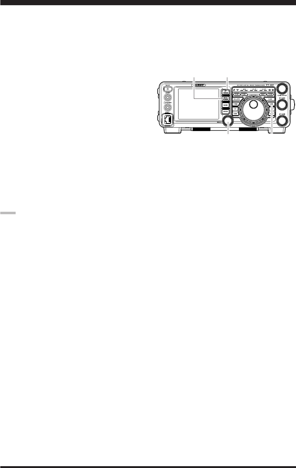
Page 81FT-991 OperaTing Manual
Section 97.401(d) of the regulations governing amateur radio in the United States permit emergency amateur commu-
nications on the spot frequency of 5167.5 kHz by stations in (or within 92.6 km of) the state of Alaska. This frequency
is only to be used when the immediate safety of human life and/or property are threatened, and is never to be used for
routine communications.
The FT-991 includes the capability for transmission and reception on 5167.5 kHz under such emergency conditions via
the Menu system. To activate this feature:
1. Press the MENU(SETUP) button to enter the Menu
mode.
2. Rotate the MULTI knob to select Menu item “149
EMERGENCY FREQ TX”.
3. Touch
[SELECT] on the LCD, then rotate the
MULTI knob to select “ENABLE.”
4. Touch
[ENTER] on the LCD to save the new set-
ting.
5. Press the MENU(SETUP) button or [BACK] on the
LCD to exit to normal operation. Emergency com-
munication on this spot frequency is now possible.
6. Press the V/M button, as necessary, to enter the
Memory mode.
7. Press the F(M-LIST) button, then touch [MCH] on
the LCD.
8. Rotate the MULTI knob to select the emergency
channel (“EMERGENCY”), which is found between
channels “510” and “01”).
note:
The receive-mode CLARIFIER functions normally
while using this frequency, but variation of the trans-
mit frequency is not possible. The full specications
of the FT-991 are not necessarily guaranteed on this
frequency, but power output and receiver sensitivity
should be fully satisfactory for the purpose of emer-
gency communication.
If you wish to disable operation capability on the
Alaska Emergency Frequency, repeat the above pro-
cedures, but set the Menu item “149 EMERGENCY
FREQ TX” to “DISABLE” in step 3.
In an emergency, note that a half-wave dipole cut
for this frequency should be approximately 45’3” on
each leg (90’6” total length). Emergency operation
on 5167.5 kHz is shared with the Alaska-Fixed Ser-
vice. This transceiver is not authorized for operation,
under the FCC Part 87, for aeronautical communica-
tions.
You may scan either the VFO or the memories of the
FT-991, and the radio will halt scanning on any fre-
quency with a signal strong enough to open the receiver
squelch.
operaTion on alaska eMergenCY freQuenCY: 5167.5 khz (u.s. version onlY)
V/M ButtonMULTI Knob
MENU(SETUP) Button F(M-LIST) Button
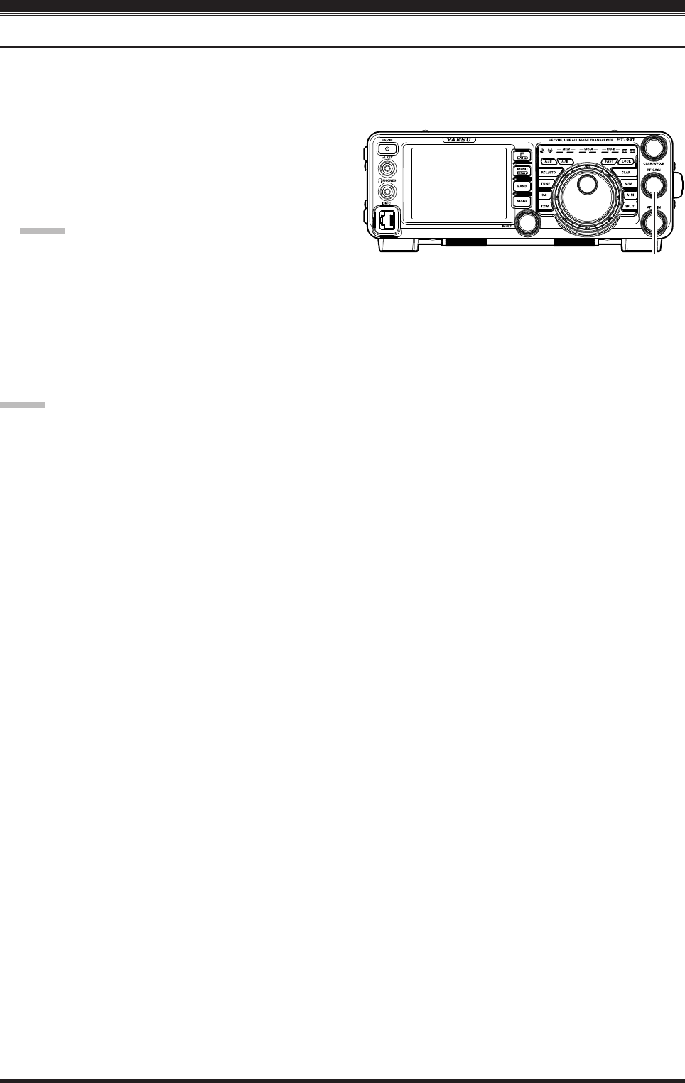
Page 82 FT-991 OperaTing Manual
vfo and MeMorY sCanning
vFo ScAnning
1. Set the VFO-A to the frequency on which you would like to begin scanning.
2. Rotate the RF GAIN knob so that the background noise is just silenced.
3. Press and hold in the microphone UP or DWN but-
ton for one second to start scanning in the specied
direction on the VFO frequency.
4. If the scanner halts on an incoming signal, the deci-
mal point between the “MHz” and “kHz” digits of
the frequency display will blink.
Advice:
If the incoming signal disappears, scanning will
resume in about ve seconds.
On the SSB/CW and SSB-based Data modes, the
scanner will pause on a received signal, then will
step across the signal very slowly, giving you
time to stop the scan, if you like. In these modes
on the VFO, the scanner does not stop, however.
5. To cancel scanning, press the PTT switch.
Advice:
If you press the microphone PTT switch during
scanning, the scanner will halt at once. However,
pressing the PTT switch during scanning will not
cause transmission.
You may select the manner in which the scanner re-
sumes while it has paused on a signal, using Menu
item “037 MIC SCAN RESUME”. The default “TIME”
(5 sec) setting will cause the scanner to resume scan-
ning after ve seconds; you may change it, however,
to resume only after the carrier has dropped out.
RF GAIN Knob
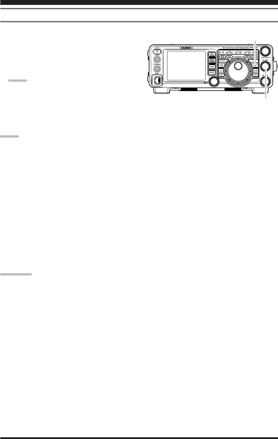
Page 83FT-991 OperaTing Manual
MeMory ScAn
1. Set the transceiver up in the “Memory” mode by
pressing the V/M button, if necessary.
2. Rotate the RF GAIN knob so that the background
noise is just silenced.
3. Press and hold in the microphone UP or DWN but-
ton for one second to start scanning in the specied
direction.
Advice:
If the scanner halts on an incoming signal, the
decimal point between the “MHz” and “kHz”
digits of the frequency display will blink.
If the incoming signal disappears, scanning will
resume in about ve seconds.
4. To cancel scanning, press the PTT witch.
Advice:
During Memory Group operation, only the channels
within the current Memory Group will be scanned.
If the scan has paused on a signal, pressing the mi-
crophone UP or DWN button will cause scanning to
resume instantly.
If you press the microphone PTT switch during
scanning, the scanner will halt at once. However,
pressing the PTT switch during scanning will not
cause transmission.
You may select the manner in which the scanner re-
sumes while it has paused on a signal, using Menu
item “037 MIC SCAN RESUME”. During memory
scanning, the default “TIME” (5 sec) setting will
cause the scanner to resume scanning after five
seconds. However, you may change this setting to
resume only after the carrier has dropped out, if you
like.
quick point:
If you have no interest in scanning, and wish to prohibit
the microphone UP/DWN buttons from initiating scan-
ning, you may disable scanning control from the mi-
crophone using Menu item “036 MIC SCAN” (set it to
“DISABLE”).
vfo and MeMorY sCanning
V/M Button
RF GAIN Knob
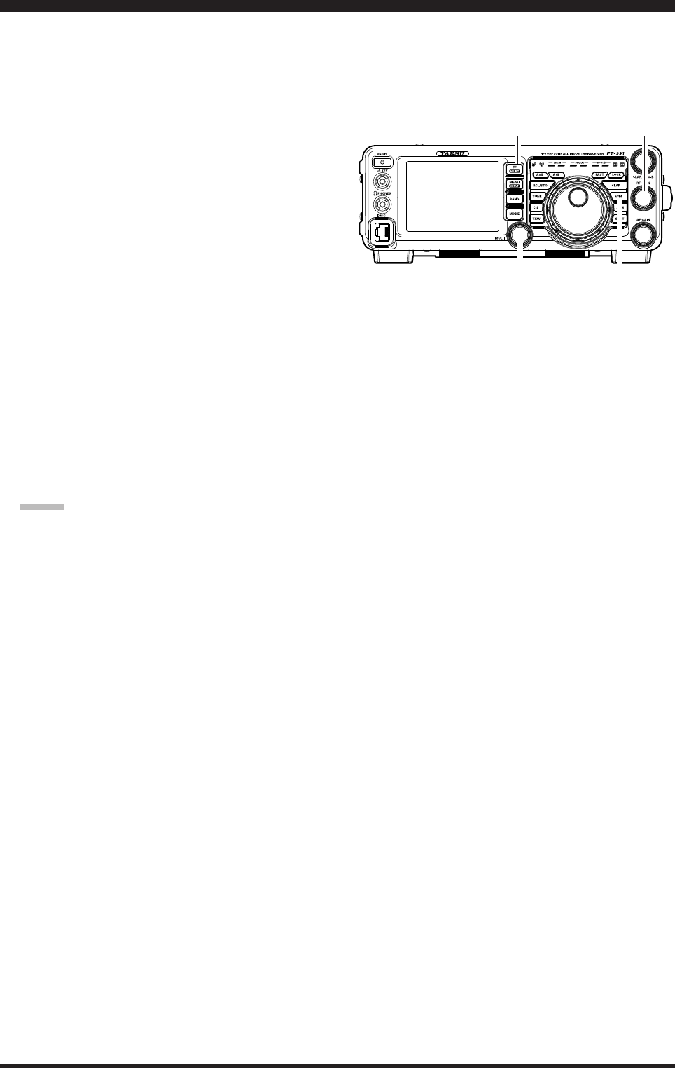
Page 84 FT-991 OperaTing Manual
pMs (prograMMable MeMorY sCanning)
To limit scanning (and manual tuning) within a particular frequency range, you can use the Programmable Memory
Scanning (PMS) feature, which utilizes nine special-purpose memory pairs (“P-1L/P-1U” through “P-9L/P-9U”). The
PMS feature is especially useful in helping you to observe any operating sub-band limits, which apply to your Amateur
license class.
1. Store the Lower and Upper tuning/scanning limit
frequencies into the memory pair “P-1L” and “P-1U”,
respectively, or any other “L/U” pair of memories in
the special PMS memory area. See page ## for de-
tails regarding memory storage.
2. Press the V/M button to enter the “Memory” mode.
3. Press the F(M-LIST) button, then touch [MCH] on
the LCD. The LEDs indicating the Memory mode
will illuminate.
4. Rotate the MULTI knob to select memory channel
“P-1L” or “P-1U”.
5. Rotate the RF GAIN knob so that the background
noise is just silenced.
6. Turn the Main Tuning Dial knob slightly (to activate
memory tuning). Tuning and scanning are now limit-
ed to the range within the P-1L/P-1U limits until you
press the V/M button to return to memory channel or
VFO operation.
7. Press and hold in the microphone UP or DWN but-
ton for one second to start scanning in the specied
direction.
Advice:
If the scanner halts on an incoming signal, the
decimal point between the “MHz” and “kHz”
digits of the frequency display will blink.
If the incoming signal disappears, scanning will
resume in about ve seconds.
On the SSB/CW and SSB-based Data modes,
the scanner will pause on a received signal, then
will step across the signal very slowly, giving
you time to stop the scan, if you like. However,
in these modes on the VFO, the scanner does not
stop.
If the scan has paused on a signal, pressing the
microphone UP or DWN button will cause scan-
ning to resume instantly.
8. If you rotate the Main Tuning Dial knob in the op-
posite direction from the current scanning direction
(in other words, you rotate the dial to the left when
scanning toward a higher frequency), the direction of
the scan will reverse.
9. If you press the microphone PTT switch during
scanning, the scanner will halt at once. Pressing the
PTT switch during scanning will not cause transmis-
sion.
V/M Button
RF GAIN Knob
MULTI Knob
F(M-LIST) Button
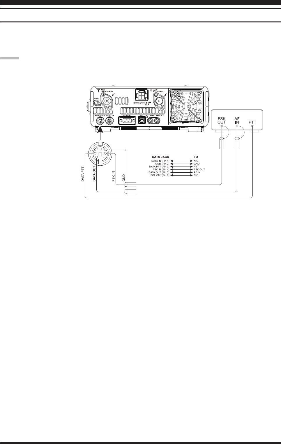
Page 85FT-991 OperaTing Manual
rTTY (radio TeleTYpe) operaTion
exAMple oF connecting rtty coMMunicAtionS device
Connect the RTTY communications TU (Terminal Unit) to the rear panel RTTY/PKT terminal. Be sure to read the in-
structions manual of the device to connect when connecting.
See page ## for details on the connections and settings to use the optional USB Interface Unit “SCU-17”.
TU
Advice:
You can adjust RTTY data output level using Menu item
“099 RTTY OUT LEVEL”.
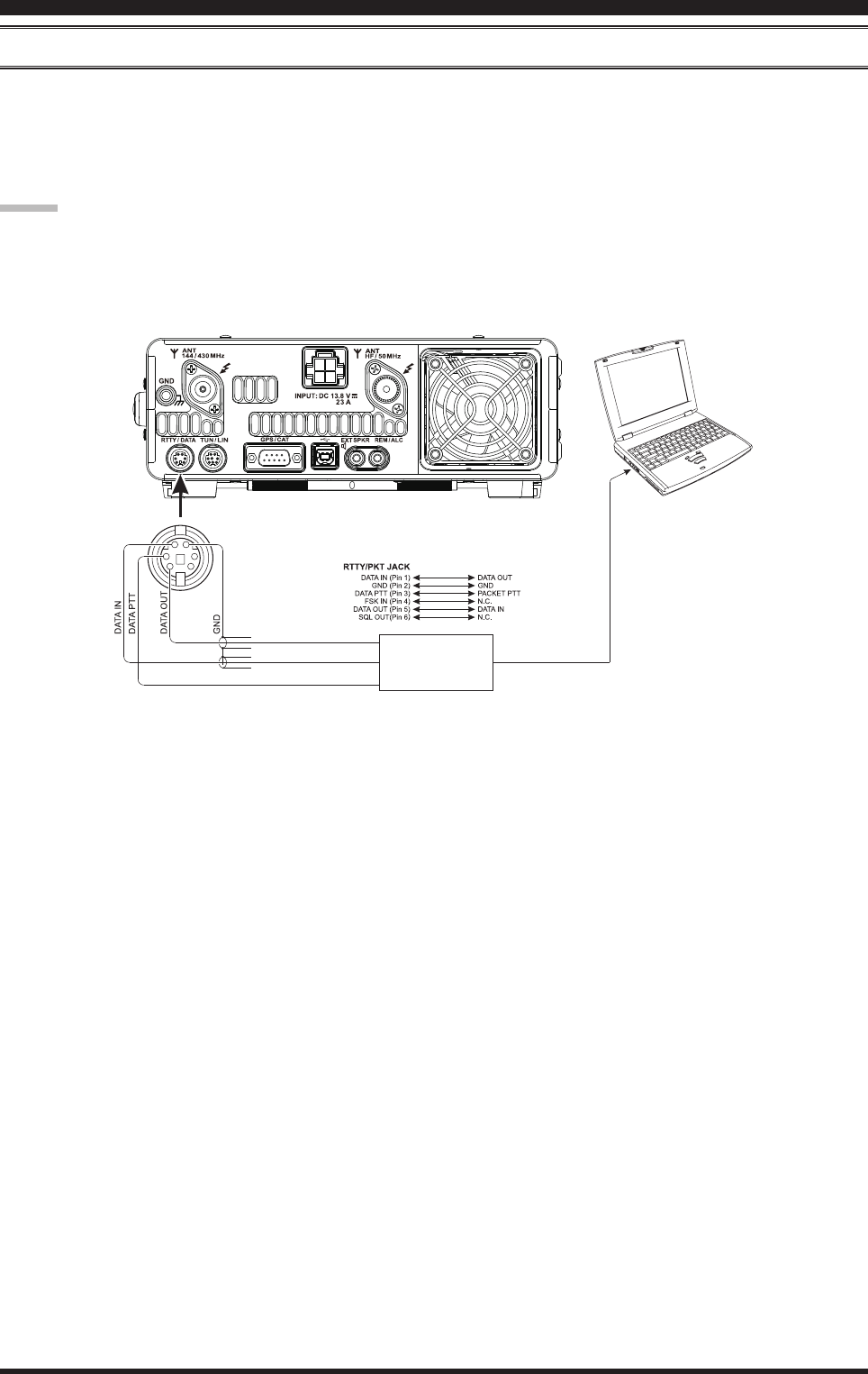
Page 86 FT-991 OperaTing Manual
exAMple oF dAtA coMMunicAtionS device
You can use commercial and free computer software for PSK data communications. See the illustration below for con-
nection to your computer.
Be sure to read the instruction manual of the device to be connected to the radio and computer.
See page ## for details on the connections and settings to use the optional USB Interface Unit “SCU-17”.
daTa (psk) operaTion
Advice:
You can set the data output level for data communi-
cations (PSK31, SSTV, etc.) using Menu item “075
DATA OUT LEVEL”.
You can set VOX DELAY in VOX operation for data
communications (PSK31, SSTV, etc.) using Menu
item “147 DATA VOX DELAY”. You can also set data
input VOX gain using Menu item “146 DATA VOX
GAIN”.
Interface device
commercially
available
To LINE IN/MIC IN,
LINE OUT/MIC OUT,
COM port, etc.

Page 87FT-991 OperaTing Manual
The Menu system of the FT-991 provides extensive customization capability, so you can set up your transceiver just the
way you want to operate it. The Menu items are grouped by general utilization category, and are numbered from “001
AGC” to “149 E/D PSK”.
Using the Menu
1. Press the MENU(SETUP) button to engage the
Menu mode.
The display will show the Menu Number, the Menu
Group Name and the Menu Item.
2. Rotate the MULTI knob to select the Menu item you
wish to modify.
3. Touch
[SELECT] on the LCD, then rotate the
MULTI knob to change the current setting of the se-
lected Menu item.
Advice:
Touch [BACK] on the LCD to cancel the setting.
4. When you have nished making your adjustments,
touch [ENTER] on the LCD to save the new set-
ting, then press the MENU(SETUP) button or touch
[BACK] on the LCD to exit to normal operation.
MULTI Knob
MENU(SETUP Button
Menu Mode

Page 88 FT-991 OperaTing Manual
Menu Mode
Group No. Menu Function Available Settings Default Value
AGC 001 FAST DELAY 20 ~4000 (20msec/step) 300msec
AGC 002 MID DELAY 20 ~4000 (20msec/step) 700msec
AGC 003 SLOW DELAY 20 ~4000 (20msec/step) 3000msec
DISPLAY 004 MY CALL TIME OFF ~5sec 1sec
DISPLAY 005 DISPLAY COLOR BLUE/GRAY/GREEN/ORANGE/PURPLE/RED/
SKY BLUE/ BLUE
DISPLAY 006 DIMMER LED 1/2 2
DISPLAY 007 DIMMER TFT 0~15 8
DISPLAY 008 BAR MTR PEAK HOLD OFF/0.5/1.0/2.0 (sec) OFF
DVS 009 RX OUT LEVEL 0 ~100 50
DVS 010 TX OUT LEVEL 0 ~100 50
KEYER 011 KEYER TYPE OFF/BUG/ELEKEY-A/ELEKEY-B/ELEKEY-Y/
ACS ELEKEY-B
KEYER 012 CW KEYER NOR/REV NOR
KEYER 013 CW WEIGHT 2.5 ~4.5 3.0
KEYER 014 BEACON TIME OFF/1 ~240sec/270 ~690sec OFF
KEYER 015 NUMBER STYLE 1290/AUNO/AUNT/A2NO/A2NT/12NO/12NT 1290
KEYER 016 CONTEST NUMBER 0 ~9999 1
KEYER 017 CW MEMORY 1 TEXT/MESSAGE TEXT
KEYER 018 CW MEMORY 2 TEXT/MESSAGE TEXT
KEYER 019 CW MEMORY 3 TEXT/MESSAGE TEXT
KEYER 020 CW MEMORY 4 TEXT/MESSAGE TEXT
KEYER 021 CW MEMORY 5 TEXT/MESSAGE TEXT
GENERAL 022 NB WIDTH 1/3/10msec 3msec
GENERAL 023 NB REJECTION 10/30/50dB 30dB
GENERAL 024 NB LEVEL 0 ~100 50dB
GENERAL 025 BEEP LEVEL 0 ~100 50
GENERAL 026 TIME ZONE -12:00 ~0:00 ~+14:00 0:00
GENERAL 027 GPS/232C SELECT GPS/RS232C GPS
GENERAL 028 232C RATE 4800/9600/19200/38400 (bps) 4800bps
GENERAL 029 232C TOT 10/100/1000/3000 (msec) 10msec
GENERAL 030 CAT RATE 4800/9600/19200/38400 (bps) 4800bps
GENERAL 031 CAT TOT 10/100/1000/3000 (msec) 10msec
GENERAL 032 CAT RTS ENABLE/DISABLE ENABLE
GENERAL 033 MEM GROUP ENABLE/DISABLE DISABLE
GENERAL 034 QUICK SPLIT FREQ -20 ~+20kHz 5kHz
GENERAL 035 TX TOT OFF/1 ~30 (min) OFF
GENERAL 036 MIC SCAN ENABLE/DISABLE ENABLE
GENERAL 037 MIC SCAN RESUME PAUSE/TIME TIME
GENERAL 038 FREQ ADJ -25 ~0~25 0
GENERAL 039 CLAR SELECT RX/TX/TRX
MODE-AM 040 AM LCUT FREQ OFF/100Hz ~1000Hz (50Hz/step) OFF
MODE-AM 041 AM LCUT SLOPE 6dB/oct / 18dB/oct 6dB/oct
MODE-AM 042 AM HCUT FREQ 700Hz ~4000Hz (50Hz/step) / OFF OFF
MODE-AM 043 AM HCUT SLOPE 6dB/oct / 18dB/oct 6dB/oct
MODE-AM 044 AM MIC SEL MIC/REAR MIC
MODE-AM 045 AM MIC GAIN MCVR/0 ~100 30
MODE-AM 046 AM OUT LEVEL 0 ~100 50
047 REAR PTT SELECT DAKY/RTS/DTR DAKY
048 REAR PORT SELECT DATA/USB DATA
049 AM DATA GAIN 0 ~100 50
MODE-CW 050 CW LCUT FREQ OFF/100Hz ~1000Hz(50Hz/step) 250Hz
MODE-CW 051 CW LCUT SLOPE 6dB/oct / 18dB/oct 18dB/oct

Page 89FT-991 OperaTing Manual
Menu Mode
Group No. Menu Function Available Settings Default Value
MODE-CW 052 CW HCUT FREQ 700Hz ~4000Hz(50Hz/step) 1200Hz
MODE-CW 053 CW HCUT SLOPE 6dB/oct / 18dB/oct 18dB/oct
MODE-CW 054 CW OUT LEVEL 0 ~100 50
MODE-CW 055 CW AUTO MODE OFF/50M/ON OFF
MODE-CW 056 CW BFO USB/LSB/AUTO USB
MODE-CW 057 CW BK-IN SEMI/FULL SEMI
MODE-CW 058 CW BK-IN DELAY 30 ~3000 (msec) 200msec
MODE-CW 059 CW WAVE SHAPE 1/2/4/6 (msec) 4msec
MODE-CW 060 CW FREQ DISPLAY DIRECT FREQ/PITCH OFFSE
PITCH OFFSE
MODE-CW 061 PC KEYING OFF/DAKY/RTS/DTR OFF
MODE-CW 062 QSK 15/20/25/30(msec) 15msec
MODE-DATA 063 DATA MODE PSK/OTHERS PSK
MODE-DATA 064 PSK TONE 1000/1500/2000(Hz) 1000Hz
MODE-DATA 065 OTHER DISP (SSB) -3000 ~0~+3000(10Hz/step) 0Hz
MODE-DATA 066 OTHER SHIFT (SSB) -3000 ~0~+3000(10Hz/step) 0Hz
MODE-DATA 067 DATA LCUT FREQ OFF/100 ~1000(Hz)(50Hz/step) 300Hz
MODE-DATA 068 DATA LCUT SLOPE 6dB/oct / 18dB/oct 18dB/oct
MODE-DATA 069 DATA HCUT FREQ 700 ~4000(Hz)(50Hz/step)/OFF 3000Hz
MODE-DATA 070 DATA HCUT SLOPE 6dB/oct / 18dB/oc 18dB/oct
MODE-DATA 071 DATA IN SELECT REAR/MIC REAR
MODE-DATA 072 DATA MIC GAIN 0 ~100 50
MODE-DATA 073 REAR PTT SELECT DAKY/RTS/DTR DAKY
MODE-DATA 074 REAR PORT SELECT DATA/USB DATA
MODE-DATA 075 DATA OUT LEVEL 0 ~100 50
MODE-FM 076 FM MIC SEL MIC/REAR MIC
MODE-FM 077 FM MIC GAIN MCVR/0 ~100 30
MODE-FM 078 FM OUT LEVEL 0 ~100 50
MODE-FM 079 REAR PTT SELECT DAKY/RTS/DTR DARY
MODE-FM 080 REAR PORT SELECT DATA/USB DATA
MODE-FM 081 FM PKT GAIN 0 ~100 50
MODE-FM 082 FM PKT MODE 1200/9600 1200
MODE-FM 083 RPT SHIFT 28MHz 0 ~1000kHz (10kHz/step) 100kHz
MODE-FM 084 RPT SHIFT 50MHz 0 ~4000kHz (10kHz/step) 1000kHz
MODE-FM 085 RPT SHIFT 144MHz 0 ~4000kHz (10kHz/step) 600kHz
MODE-FM 086 RPT SHIFT 430MHz 0 ~9990kHz (10kHz/step) 5000kHz
MODE-FM 087 ARS 144MHz OFF/ON ON
MODE-FM 088 ARS 430MHz OFF/ON ON
089 DCS POLARITY Tn-Rn/Tn-Riv/Tiv-Rn/Tin-Riv Tn-Rn
090 AMS TX MODE AUTO/DN/VW/ANALOG AUTO
091 RADIO ID *****
MODE-RTTY 092 RTTY LCUT FREQ OFF/100Hz ~1000Hz (50Hz/step) 300Hz
MODE-RTTY 093 RTTY LCUT SLOPE 6dB/oct / 18dB/oct 18dB/oct
MODE-RTTY 094 RTTY HCUT FREQ 700Hz ~4000Hz (50Hz/step) / OFF 3000Hz
MODE-RTTY 095 RTTY HCUT SLOPE 6dB/oct / 18dB/oct 18dB/oct
MODE-RTTY 096 RTTY SHIFT PORT SHIFT/DTR/RTS SHIFT
MODE-RTTY 097 POLARITY-R NOR/REV NOR
MODE-RTTY 098 POLARITY-T NOR/REV NOR
MODE-RTTY 099 RTTY OUT LEVEL 0 ~100 50
MODE-RTTY 100 RTTY SHIFT 170/200/425/850 (Hz) 170Hz
MODE-RTTY 101 RTTY MARK FREQ 1275/2125 (Hz) 2125Hz
MODE-SSB 102 SSB LCUT FREQ OFF/100Hz ~1000Hz (50Hz/step) 100Hz
MODE-SSB 103 SSB LCUT SLOPE 6dB/oct / 18dB/oct 6dB/oct
MODE-SSB 104 SSB HCUT FREQ 700Hz ~4000Hz (50Hz/step) / OFF 3000Hz

Page 90 FT-991 OperaTing Manual
Menu Mode
Group No. Menu Function Available Settings Default Value
MODE-SSB 105 SSB HCUT SLOPE 6dB/oct / 18dB/oct 6dB/oct
MODE-SSB 106 SSB MIC SELECT MIC/REAR MIC
MODE-SSB 107 SSB OUT LEVEL 0 ~100 50
108 REAR PTT SELECT DAKY DAKY
109 REAR PORT SELECT DATA/USB DATA
MODE-SSB 110 SSB TX BPF 100-3000/100-2900/200-2800/300-2700/400-
2600 300-2700
RX-DSP 111 APF WIDTH NARROW/MEDIUM/WIDE MEDIUM
RX-DSP 112 CONTOUR LEVE -40 ~0~20 -15
RX-DSP 113 CONTOUR WIDTH 1 ~11 10
RX-DSP 114 IF NOTCH WIDTH NARROW/WIDE WIDE
AF-SCOPE 115 DISPLAY MODE SPECTRUM/WATER FALL SPECTRUM
116 START CYCLE OFF/3/5/10 (sec) OFF
117 START DIAL SPEED 0.25kHz/0.5kHz/1kHz/2kHz/4kHz (sec) 1kHz/sec
118 SPAN FREQ 50/100/200/500/1000 (kHz) 100kHz
TX AUDIO 119 PRMTRC EQ1 FREQ OFF/100 ~700 (100/step) OFF
TX AUDIO 120 PRMTRC EQ1 LEVEL -20 ~0~+10 5
TX AUDIO 121 PRMTRC EQ1 BWTH 1 ~10 10
TX AUDIO 122 PRMTRC EQ2 FREQ OFF/700 ~1500 (100/step) OFF
TX AUDIO 123 PRMTRC EQ2 LEVEL -20 ~0~+10 5
TX AUDIO 124 PRMTRC EQ2 BWTH 1 ~10 10
TX AUDIO 125 PRMTRC EQ3 FREQ OFF/1500 ~3200 (100/step) OFF
TX AUDIO 126 PRMTRC EQ3 LEVEL -20 ~0~+10 5
TX AUDIO 127 PRMTRC EQ3 BWTH 1 ~10 10
TX AUDIO 128 P-PRMTRC EQ1 FREQ OFF/100 ~700 (100/step) 200
TX AUDIO 129 P-PRMTRC EQ1 LEVEL -20 ~0~10 0
TX AUDIO 130 P-PRMTRC EQ1 BWTH 1 ~10 2
TX AUDIO 131 P-PRMTRC EQ2 FREQ OFF/700 ~1500 (100/step) 800
TX AUDIO 132 P-PRMTRC EQ2 LEVEL -20 ~0~10 0
TX AUDIO 133 P-PRMTRC EQ2 BWTH 1 ~10 1
TX AUDIO 134 P-PRMTRC EQ3 FREQ OFF/1500 ~3200 (100/step) 2100
TX AUDIO 135 P-PRMTRC EQ3 LEVEL -20 ~0~10 0
TX AUDIO 136 P-PRMTRC EQ3 BWTH 1 ~10 1
TX GNRL 137 HF TX MAX POWER 5 ~100 100
TX GNRL 138 50M TX MAX POWER 0 ~100 100
TX GNRL 139 144M TX MAX POWER 0 ~50 50
TX GNRL 140 430M TX MAX POWER 0 ~50 50
TX GNRL 141 TUNER SELECT OFF/INTERNAL/EXTERNAL/ATAS/LAMP INTERNAL
TX GNRL 142 VOX SELECT MIC/DATA MIC
TX GNRL 143 VOX GAIN 0 ~100 50
TX GNRL 144 VOX DELAY 30 ~3000 (msec) 500msec
TX GNRL 145 ANTI VOX GAIN 0 ~100 50
TX GNRL 146 DATA VOX GAIN 0 ~100 50
TX GNRL 147 DATA VOX DELAY 30 ~3000 (msec) 100msec
TX GNRL 148 ANTI DVOX GAIN 0 ~100 0
TX GNRL 149 EMERGENCY FREQ TX DISABLE/ENABLE DISABLE

Page 91FT-991 OperaTing Manual
SpecificationS
General
Rx Frequency Range: 30 kHz - 55.999995 MHz
118 MHz - 163.999995 MHz
420 MHz - 469.999995 MHz
Tx Frequency Ranges: 1.8 MHz - 430 MHz (Amateur bands only)
Frequency Stability: ±0.5 ppm (after 1 minute @+14 °F to +140 °F [–10 °C to +60 °C])
Operating Temperature Range: +14 °F to +122 °F (–10 °C to +50 °C)
Emission Modes: A1A, A3E, J3E, F3E, F7W, F1B, F1D, F2D, G1B
Frequency Steps: 5/10 Hz (SSB, CW), 50/100 Hz (AM, FM)
Antenna Impedance: 50 Ohms, unbalanced
16.7 - 150 Ohms, unbalanced (1.8 MHz - 29.7 MHz)
25 - 100 Ohms, unbalanced (50 MHz - 54 MHz)
(Tuner ON, 1.8 MHz - 50 MHz Amateur bands, TX only)
Power Consumption (Approx.): Rx (no signal) 1.8 A
Rx (signal present) 2.2 A
Tx (HF/50 MHz, 100 W) 22 A, (144/430 MHz, 50 W) 15 A
Supply Voltage: DC 13.8 V ± 15 % (Negative Ground)
Dimensions (WxHxD): 9.01” x 3.15” x 9.96” (229 x 80 x 253 mm)
Weight (Approx.): 9.46 lbs (4.3 kg)
Transmitter
Power Output: HF/50 MHz: 5 - 100 watts (2.5 - 25 watts AM carrier)
144/430 MHz: 5 - 50 watts (2.5 - 12.5 watts AM carrier)
Modulation Types: J3E: Balanced,
A3E: Low-Level (Early Stage),
F3E: Variable Reactance
F7W: 4FSK (C4FM)
Maximum FM Deviation: ±5.0 kHz/±2.5 kHz
Harmonic Radiation: Better than –50 dB (below 30 MHz)
Better than –60 dB (above 30 MHz)
SSB Carrier Suppression: At least 50 dB below peak output
Undesired Sideband Suppression: At least 50 dB below peak output
Bandwidth: 3 kHz (LSB/USB), 500 Hz (CW), 6 kHz (AM), 16 kHz (FM)
Audio Response (SSB): Not more than –6 dB from 300 to 2700 Hz
Microphone Impedance: 600 Ohms (200 to 10 kOhms)

Page 92 FT-991 OperaTing Manual
SpecificationS
Receiver
Circuit Type: SSB/CW/AM: Triple-conversion Superheterodyne
FM: Double-conversion Superheterodyne
Intermediate Frequencies: 69.450 MHz
9.000 MHz (SSB, CW, AM)
24 kHz (SSB, CW, AM)
450 kHz (FM)
Sensitivity: SSB/CW (10 dB S+N/N)
0.158 µV (1.8 - 30 MHz) (RF AMP 2 “ON”)
0.125 µV (50 - 54 MHz) (RF AMP 2 “ON”)
0.125 µV (144 - 146 MHz) (RF AMP 2 “ON”)
0.125 µV (430 - 440 MHz) (RF AMP 2 “ON”)
AM (10 dB S+N/N, 30 % modulation @400 Hz)
28 µV (0.1 - 1.8 MHz) (RF AMP 2 “ON”)
2 µV (1.8 - 30 MHz) (RF AMP 2 “ON”)
1 µV (50 - 54 MHz) (RF AMP 2 “ON”)
FM (12 dB SINAD)
0.5 µV (1.8 - 30 MHz) (RF AMP 2 “ON”)
0.25 µV (50 - 54 MHz) (RF AMP 2 “ON”)
0.18 µV (144 - 146 MHz) (RF AMP 2 “ON”)
0.18 µV (430 - 440 MHz) (RF AMP 2 “ON”)
Thereisnospecicationforfrequencyrangesnotlisted.
Selectivity (WIDTH: Center): Mode –6 dB –60 dB
SSB/CW (Width=2.4 kHz) 2.4 kHz or better 3.6 kHz or less
CW-N (Width =500 Hz) 0.5 kHz or better 750 Hz or less
AM 6 kHz or better 15 kHz or less
FM 12 kHz or better 30 kHz or less
FM-N 9 kHz or better 25 kHz or less
Image Rejection: 70 dB or better (1.8 MHz - 50 MHz Amateur bands)
60 dB or better (144/430 MHz Amateur band)
Maximum Audio Output: 2.5 W into 4 Ohms with 10% THD
Audio Output Impedance: 4 to 16 Ohms (8 Ohms: nominal)
Conducted Radiation: Less than 4000 uuW
Specications are subject to change, in the interest of technical improvement, without notice or obligation, and are
guaranteed only within the amateur bands.

Page 93FT-991 OperaTing Manual
noTe
1. Changes or modifications to this device not expressly approved by YAESU MUSEN could void the user’s
authorization to operate this device.
2. This device complies with part 15 of the FCC Rules. Operation is subject to the following two conditions; (1)
this device may not cause harmful interference, and (2) this device must accept any interference including
interference that may cause undesired operation.
3. The scanning receiver in this equipment is incapable of tuning, or readily being altered, by the User to operate
within the frequency bands allocated to the Domestic public Cellular Telecommunications Service in Part 22.
DECLARATION BY MANUFACTURER
The scanner receiver is not a digital scanner and is incapable of being converted or modied into a digital scanner
receiver by any user.
WARNING: MODIFICATION OF THIS DEVICE TO RECEIVE CELLULAR RADIOTELEPHONE SERVICE
SIGNALS IS PROHIBITED UNDER FCC RULES AND FEDERAL LAW.
CAN ICES-3 (B) / NMB-3 (B)
This equipment has been tested and found to comply with the limits for a Class B digital device, pursuant to Part
15 of the FCC Rules. These limits are designed to provide reasonable protection against harmful interference
in a residential installation. This equipment generates, uses and can radiate radio frequency energy and, if not
installed and used in accordance with the instructions, may cause harmful interference to radio communications.
However, there is no guarantee that interference will not occur in a particular installation.
If this equipment does cause harmful interference to radio or television reception, which can be determined by
turning the equipment off and on, the user is encouraged to try to correct the interference by one or more of the
following measures:
Increase the separation between the equipment and receiver.
Connect the equipment into an outlet on a circuit different from that to which the receiver is connected.
Consult the dealer or an experienced radio/TV technician for help.
This device complies with Industry Canada licence-exempt RSS standard(s). Operation is subject to the following
two conditions: (1) this device may not cause interference, and (2) this device must accept any interference,
including interference that may cause undesired operation of the device.
Le présent appareil est conforme aux CNR d’Industrie Canada applicables aux appareils radio exempts de
licence. L’exploitation est autorisée aux deux conditions suivantes : (1) l’appareil ne doit pas produire de
brouillage, et (2) l'utilisateur de l’appareil doit accepter tout brouillage radioélectrique subi, même si le brouillage
est susceptible d’en compromettre le fonctionnement.

Copyright 2014
YAESU MUSEN CO., LTD.
All rights reserved
No portion of this manual
may be reproduced without
the permission of
YAESU MUSEN CO., LTD.
Printed in Japan