Zebra Technologies RFID-M4E-01 Multiprotocol RFID Encoder User Manual

Zebra Technologies Corporation Multiprotocol RFID Encoder

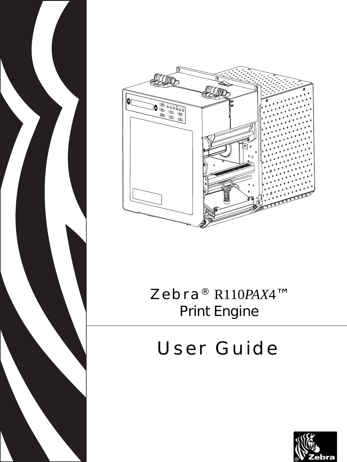
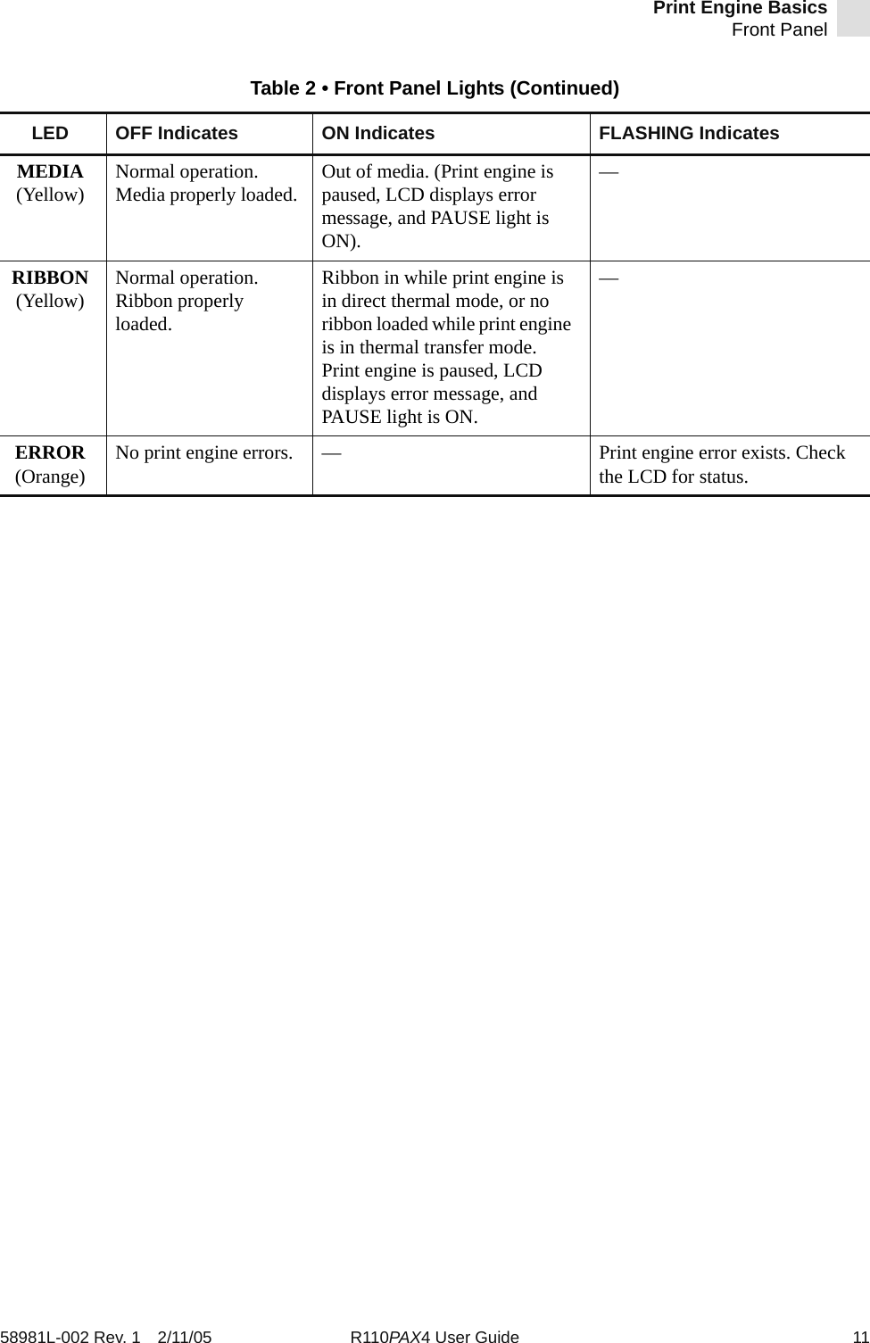
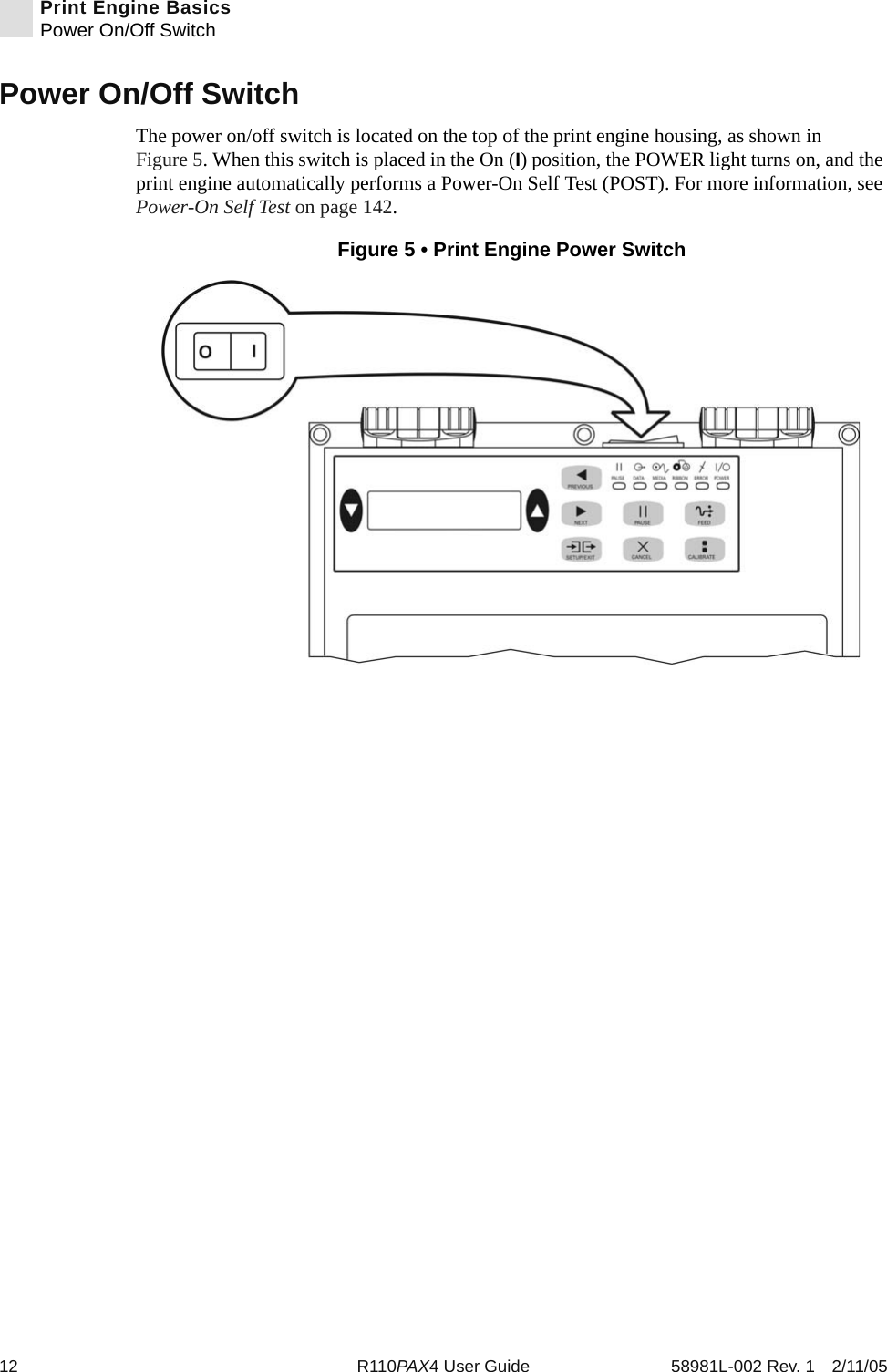
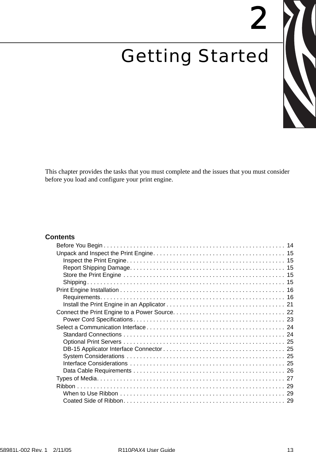
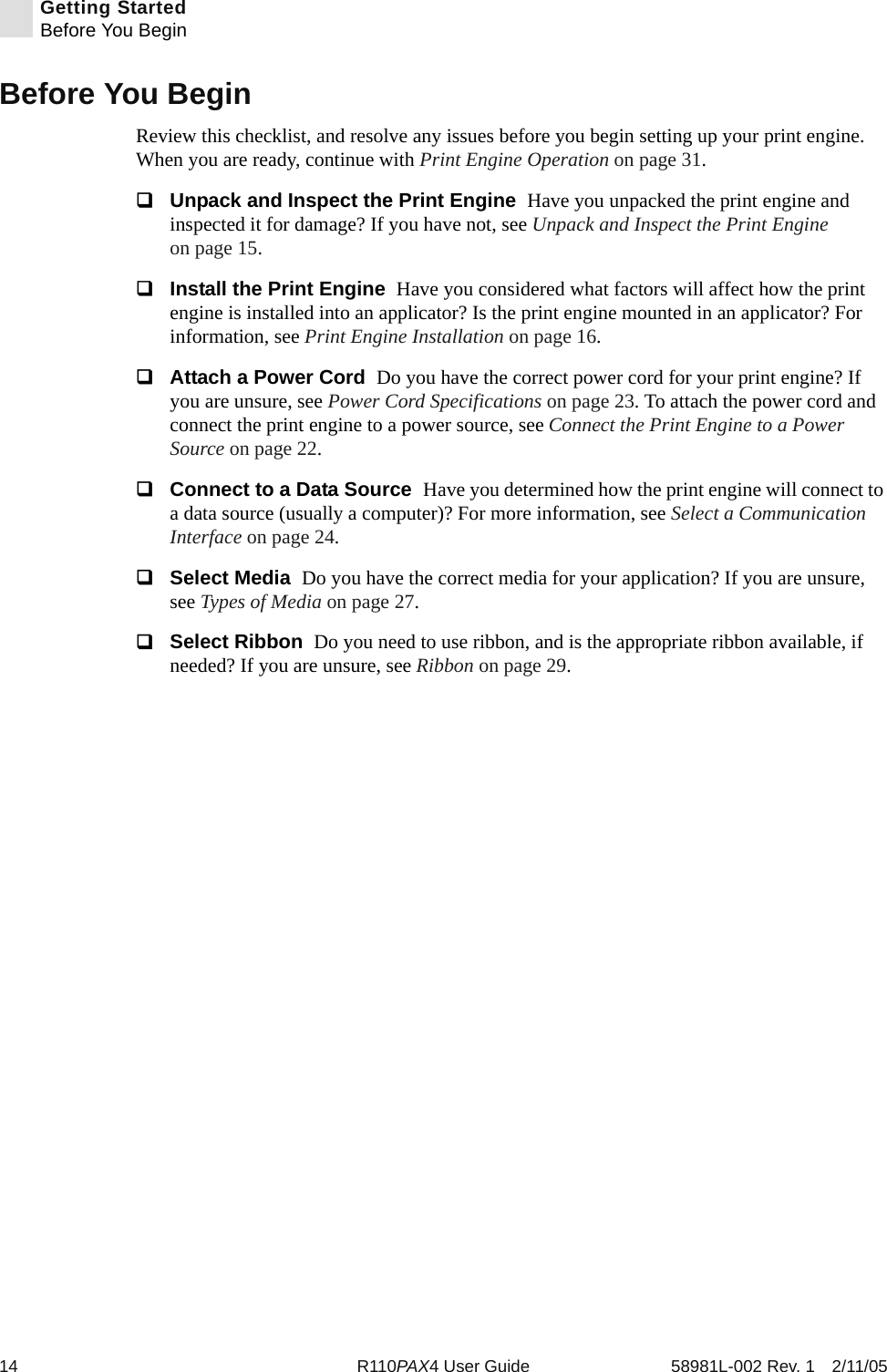
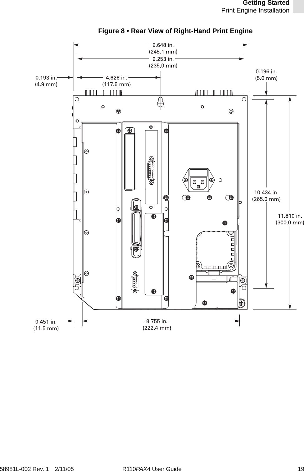
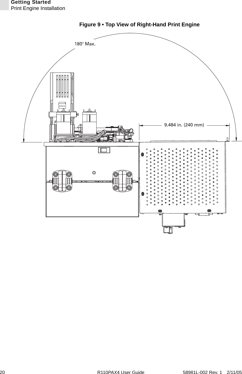
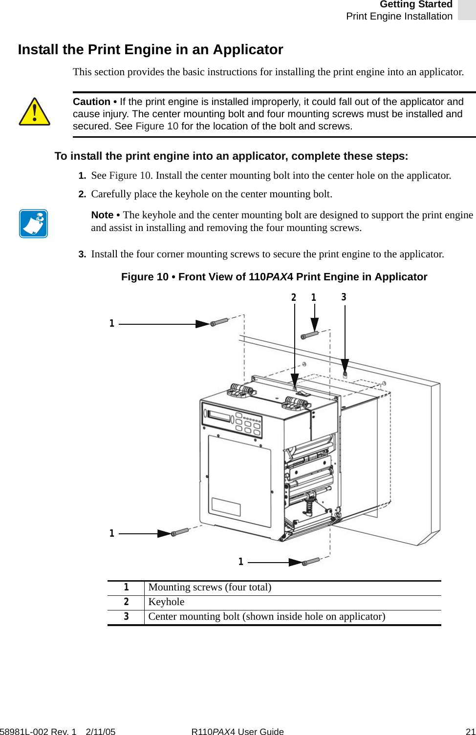
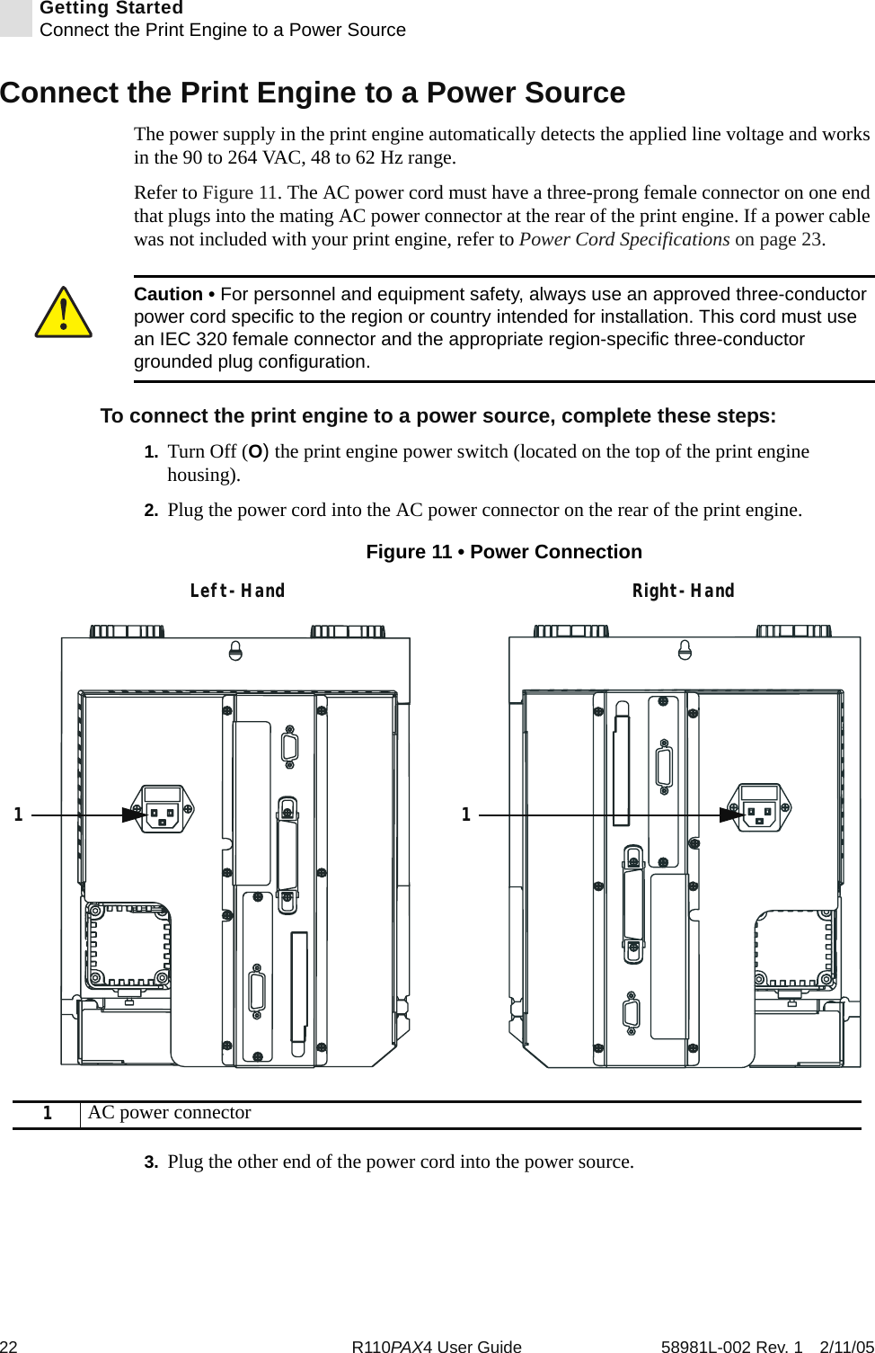
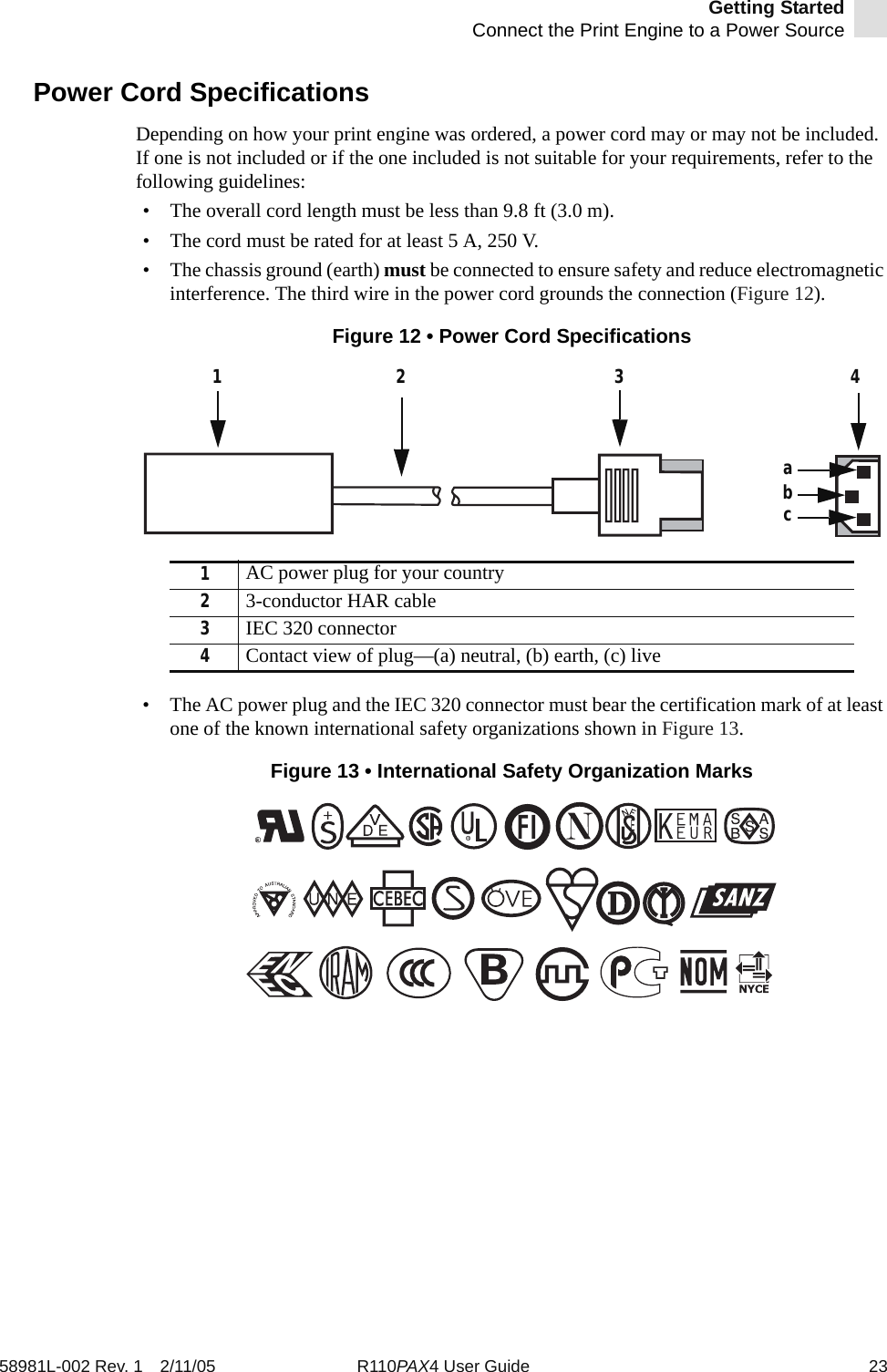
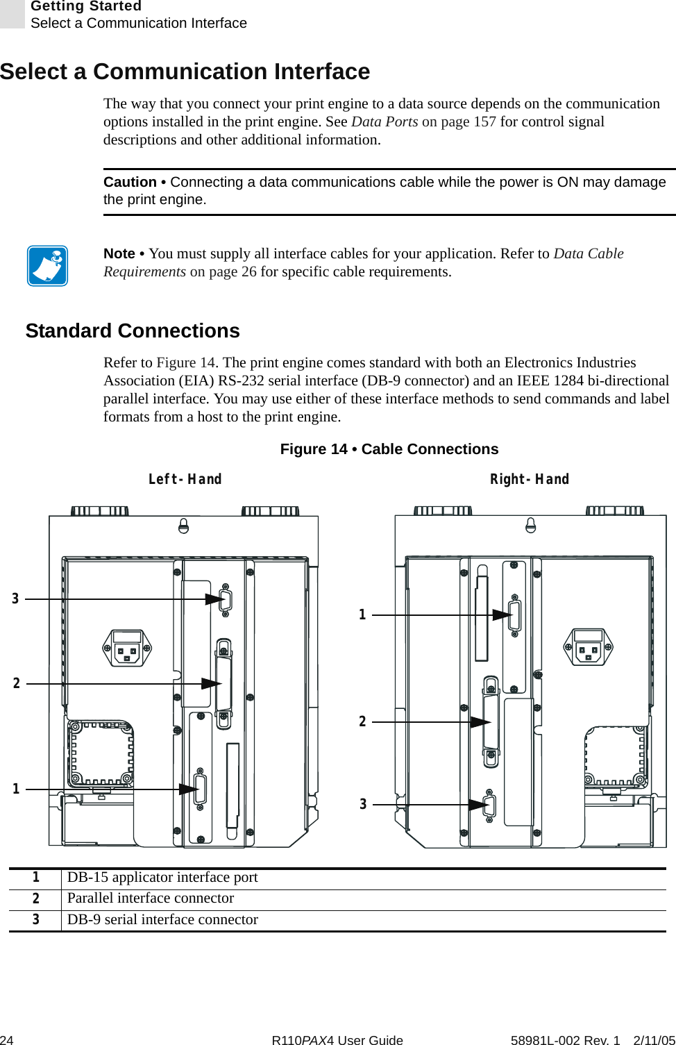
Users Manual AX4 Part 1

 Zebra® R110PAX4™Print EngineUser Guide
Customer Order # 58981L-002Manufacturer Part # 58981L-002 Rev. 1© 2005 ZIH Corp.The copyrights in this manual and the label print engine described therein are owned by Zebra Technologies. Unauthorized reproduction of this manual or the software in the label print engine may result in imprisonment of up to one year and fines of up to $10,000 (17 U.S.C.506). Copyright violators may be subject to civil liability.All product names and numbers are Zebra trademarks, and Zebra, the Zebra logo, ZPL, ZPL II, ZebraNet, ZebraLink, are registered trademarks of ZIH Corp. All rights reserved.All other brand names, product names, or trademarks belong to their respective holders.
58981L-002 Rev. 1 2/11/05 R110PAX4 User Guide iiiContentsAbout This Document . . . . . . . . . . . . . . . . . . . . . . . . . . . . . . . . . . . . . . . . . . . . . . . 1Who Should Use This Document . . . . . . . . . . . . . . . . . . . . . . . . . . . . . . . . . . . . . . . . . . . .  2How This Document Is Organized  . . . . . . . . . . . . . . . . . . . . . . . . . . . . . . . . . . . . . . . . . . .  2Contacts . . . . . . . . . . . . . . . . . . . . . . . . . . . . . . . . . . . . . . . . . . . . . . . . . . . . . . . . . . . . . . .  3Support . . . . . . . . . . . . . . . . . . . . . . . . . . . . . . . . . . . . . . . . . . . . . . . . . . . . . . . . . . . . . 3Document Conventions. . . . . . . . . . . . . . . . . . . . . . . . . . . . . . . . . . . . . . . . . . . . . . . . . . . .  4Related Documents  . . . . . . . . . . . . . . . . . . . . . . . . . . . . . . . . . . . . . . . . . . . . . . . . . . . . . .  51 • Print Engine Basics . . . . . . . . . . . . . . . . . . . . . . . . . . . . . . . . . . . . . . . . . . . . . . 7Print Engine Exterior View  . . . . . . . . . . . . . . . . . . . . . . . . . . . . . . . . . . . . . . . . . . . . . . . . .  8Front Panel . . . . . . . . . . . . . . . . . . . . . . . . . . . . . . . . . . . . . . . . . . . . . . . . . . . . . . . . . . . . .  9Front Panel Buttons . . . . . . . . . . . . . . . . . . . . . . . . . . . . . . . . . . . . . . . . . . . . . . . . . . .  9Front Panel Indicator Lights (LEDs) . . . . . . . . . . . . . . . . . . . . . . . . . . . . . . . . . . . . . .  10Power On/Off Switch. . . . . . . . . . . . . . . . . . . . . . . . . . . . . . . . . . . . . . . . . . . . . . . . . . . . .  122 • Getting Started . . . . . . . . . . . . . . . . . . . . . . . . . . . . . . . . . . . . . . . . . . . . . . . . .  13Before You Begin  . . . . . . . . . . . . . . . . . . . . . . . . . . . . . . . . . . . . . . . . . . . . . . . . . . . . . . .  14Unpack and Inspect the Print Engine . . . . . . . . . . . . . . . . . . . . . . . . . . . . . . . . . . . . . . . .  15Inspect the Print Engine . . . . . . . . . . . . . . . . . . . . . . . . . . . . . . . . . . . . . . . . . . . . . . .  15Report Shipping Damage . . . . . . . . . . . . . . . . . . . . . . . . . . . . . . . . . . . . . . . . . . . . . .  15Store the Print Engine. . . . . . . . . . . . . . . . . . . . . . . . . . . . . . . . . . . . . . . . . . . . . . . . .  15Shipping . . . . . . . . . . . . . . . . . . . . . . . . . . . . . . . . . . . . . . . . . . . . . . . . . . . . . . . . . . .  15Print Engine Installation  . . . . . . . . . . . . . . . . . . . . . . . . . . . . . . . . . . . . . . . . . . . . . . . . . .  16Requirements . . . . . . . . . . . . . . . . . . . . . . . . . . . . . . . . . . . . . . . . . . . . . . . . . . . . . . .  16Install the Print Engine in an Applicator . . . . . . . . . . . . . . . . . . . . . . . . . . . . . . . . . . .  21Connect the Print Engine to a Power Source . . . . . . . . . . . . . . . . . . . . . . . . . . . . . . . . . .  22Power Cord Specifications . . . . . . . . . . . . . . . . . . . . . . . . . . . . . . . . . . . . . . . . . . . . .  23
iv R110PAX4 User Guide 58981L-002 Rev. 1 2/11/05ContentsSelect a Communication Interface . . . . . . . . . . . . . . . . . . . . . . . . . . . . . . . . . . . . . . . . . .  24Standard Connections  . . . . . . . . . . . . . . . . . . . . . . . . . . . . . . . . . . . . . . . . . . . . . . . .  24Optional Print Servers. . . . . . . . . . . . . . . . . . . . . . . . . . . . . . . . . . . . . . . . . . . . . . . . .  25DB-15 Applicator Interface Connector  . . . . . . . . . . . . . . . . . . . . . . . . . . . . . . . . . . . .  25System Considerations. . . . . . . . . . . . . . . . . . . . . . . . . . . . . . . . . . . . . . . . . . . . . . . .  25Interface Considerations. . . . . . . . . . . . . . . . . . . . . . . . . . . . . . . . . . . . . . . . . . . . . . .  25Data Cable Requirements. . . . . . . . . . . . . . . . . . . . . . . . . . . . . . . . . . . . . . . . . . . . . .  26Types of Media . . . . . . . . . . . . . . . . . . . . . . . . . . . . . . . . . . . . . . . . . . . . . . . . . . . . . . . . . 27Ribbon. . . . . . . . . . . . . . . . . . . . . . . . . . . . . . . . . . . . . . . . . . . . . . . . . . . . . . . . . . . . . . . .  29When to Use Ribbon. . . . . . . . . . . . . . . . . . . . . . . . . . . . . . . . . . . . . . . . . . . . . . . . . .  29Coated Side of Ribbon . . . . . . . . . . . . . . . . . . . . . . . . . . . . . . . . . . . . . . . . . . . . . . . .  293 • Print Engine Operation  . . . . . . . . . . . . . . . . . . . . . . . . . . . . . . . . . . . . . . . . . . 31Load Media . . . . . . . . . . . . . . . . . . . . . . . . . . . . . . . . . . . . . . . . . . . . . . . . . . . . . . . . . . . .  32Load Ribbon . . . . . . . . . . . . . . . . . . . . . . . . . . . . . . . . . . . . . . . . . . . . . . . . . . . . . . . . . . .  38Remove Used Ribbon. . . . . . . . . . . . . . . . . . . . . . . . . . . . . . . . . . . . . . . . . . . . . . . . . . . .  43Calibrate the Print Engine. . . . . . . . . . . . . . . . . . . . . . . . . . . . . . . . . . . . . . . . . . . . . . . . .  44Adjust Media Sensors. . . . . . . . . . . . . . . . . . . . . . . . . . . . . . . . . . . . . . . . . . . . . . . . . . . .  46Reflective Media Sensor. . . . . . . . . . . . . . . . . . . . . . . . . . . . . . . . . . . . . . . . . . . . . . .  46Transmissive Media Sensor . . . . . . . . . . . . . . . . . . . . . . . . . . . . . . . . . . . . . . . . . . . .  464 • Print Engine Configuration . . . . . . . . . . . . . . . . . . . . . . . . . . . . . . . . . . . . . . . 49Overview. . . . . . . . . . . . . . . . . . . . . . . . . . . . . . . . . . . . . . . . . . . . . . . . . . . . . . . . . . . . . .  50Enter Setup Mode. . . . . . . . . . . . . . . . . . . . . . . . . . . . . . . . . . . . . . . . . . . . . . . . . . . .  50Exit Setup Mode . . . . . . . . . . . . . . . . . . . . . . . . . . . . . . . . . . . . . . . . . . . . . . . . . . . . .  51Print a Configuration Label . . . . . . . . . . . . . . . . . . . . . . . . . . . . . . . . . . . . . . . . . . . . . . . .  52Print a Network Configuration Label . . . . . . . . . . . . . . . . . . . . . . . . . . . . . . . . . . . . . . . . .  53Changing Password-Protected Parameters . . . . . . . . . . . . . . . . . . . . . . . . . . . . . . . . . . .  54Default Password Value . . . . . . . . . . . . . . . . . . . . . . . . . . . . . . . . . . . . . . . . . . . . . . .  54Disable the Password Protection Feature  . . . . . . . . . . . . . . . . . . . . . . . . . . . . . . . . .  54Front Panel LCD . . . . . . . . . . . . . . . . . . . . . . . . . . . . . . . . . . . . . . . . . . . . . . . . . . . . . . . .  55ZebraNet®Wired and Wireless Print Server LCD Displays . . . . . . . . . . . . . . . . . . . .  74RFID LCD Displays. . . . . . . . . . . . . . . . . . . . . . . . . . . . . . . . . . . . . . . . . . . . . . . . . . .  765 • RFID Guidelines . . . . . . . . . . . . . . . . . . . . . . . . . . . . . . . . . . . . . . . . . . . . . . . . 81Overview. . . . . . . . . . . . . . . . . . . . . . . . . . . . . . . . . . . . . . . . . . . . . . . . . . . . . . . . . . . . . .  83Transponder Placement . . . . . . . . . . . . . . . . . . . . . . . . . . . . . . . . . . . . . . . . . . . . . . .  83ZPL Commands for RFID Applications. . . . . . . . . . . . . . . . . . . . . . . . . . . . . . . . . . . .  83Electronic Product Code (EPC)  . . . . . . . . . . . . . . . . . . . . . . . . . . . . . . . . . . . . . . . . .  84EPC Structure in RFID Labels  . . . . . . . . . . . . . . . . . . . . . . . . . . . . . . . . . . . . . . . . . .  84XML-Enabled Printing. . . . . . . . . . . . . . . . . . . . . . . . . . . . . . . . . . . . . . . . . . . . . . . . .  84Getting Started with RFID . . . . . . . . . . . . . . . . . . . . . . . . . . . . . . . . . . . . . . . . . . . . . . . . .  85
Contents58981L-002 Rev. 1 2/11/05 R110PAX4 User Guide vCreating Basic RFID Label Formats . . . . . . . . . . . . . . . . . . . . . . . . . . . . . . . . . . . . . . . . .  86RFID Label Format 1—Write a 96-bit Tag in Hexadecimal. . . . . . . . . . . . . . . . . . . . .  87RFID Label Format 2—Write a 64-bit Tag in Hexadecimal. . . . . . . . . . . . . . . . . . . . .  88RFID Label Format 3—Write a 96-bit Tag in ASCII  . . . . . . . . . . . . . . . . . . . . . . . . . .  89RFID Label Format 4—Read Data from Tag and Print on Label  . . . . . . . . . . . . . . . .  90RFID Label Format 5—Write Tag, Read Tag, and Print Data on Label  . . . . . . . . . . .  91RFID Label Format 6—Write Tag, Read Tag, and Return Results to Host. . . . . . . . .  93ZPL II Commands for RFID  . . . . . . . . . . . . . . . . . . . . . . . . . . . . . . . . . . . . . . . . . . . . . . .  95^HR Calibrate RFID Transponder Position   . . . . . . . . . . . . . . . . . . . . . . . . . . . . . . . . . .  96^HV Host Verification  . . . . . . . . . . . . . . . . . . . . . . . . . . . . . . . . . . . . . . . . . . . . . . . . . . .  98^RB Define EPC Data Structure   . . . . . . . . . . . . . . . . . . . . . . . . . . . . . . . . . . . . . . . . . .  99^RF Read or Write RFID Format  . . . . . . . . . . . . . . . . . . . . . . . . . . . . . . . . . . . . . . . . .  102^RM Enable RFID Motion . . . . . . . . . . . . . . . . . . . . . . . . . . . . . . . . . . . . . . . . . . . . . . .  104^RN Detect Multiple RFID Tags in Encoding Field . . . . . . . . . . . . . . . . . . . . . . . . . . . .  105~RO Reset Advanced Counters  . . . . . . . . . . . . . . . . . . . . . . . . . . . . . . . . . . . . . . . . . .  106^RR Specify RFID Retries for a Block  . . . . . . . . . . . . . . . . . . . . . . . . . . . . . . . . . . . . .  108^RS RFID Setup   . . . . . . . . . . . . . . . . . . . . . . . . . . . . . . . . . . . . . . . . . . . . . . . . . . . . .  109^RT Read RFID Tag   . . . . . . . . . . . . . . . . . . . . . . . . . . . . . . . . . . . . . . . . . . . . . . . . . . .113^RW Set RFID Read and Write Power Levels  . . . . . . . . . . . . . . . . . . . . . . . . . . . . . . . .115^RZ Set RFID Tag Password . . . . . . . . . . . . . . . . . . . . . . . . . . . . . . . . . . . . . . . . . . . . .116^WT Write Tag  . . . . . . . . . . . . . . . . . . . . . . . . . . . . . . . . . . . . . . . . . . . . . . . . . . . . . . . .117^WV Verify RFID Write Operation . . . . . . . . . . . . . . . . . . . . . . . . . . . . . . . . . . . . . . . . . .1196 • Routine Maintenance   . . . . . . . . . . . . . . . . . . . . . . . . . . . . . . . . . . . . . . . . . . 121Cleaning Schedule . . . . . . . . . . . . . . . . . . . . . . . . . . . . . . . . . . . . . . . . . . . . . . . . . . . . .  122Clean Exterior . . . . . . . . . . . . . . . . . . . . . . . . . . . . . . . . . . . . . . . . . . . . . . . . . . . . . . . . . 122Clean Interior  . . . . . . . . . . . . . . . . . . . . . . . . . . . . . . . . . . . . . . . . . . . . . . . . . . . . . . . . . 123Clean the Sensors  . . . . . . . . . . . . . . . . . . . . . . . . . . . . . . . . . . . . . . . . . . . . . . . . . .  123Clean the Printhead and Platen Roller . . . . . . . . . . . . . . . . . . . . . . . . . . . . . . . . . . .  125Toggle Positioning. . . . . . . . . . . . . . . . . . . . . . . . . . . . . . . . . . . . . . . . . . . . . . . . . . . . . .  127Printhead Pressure Adjustment  . . . . . . . . . . . . . . . . . . . . . . . . . . . . . . . . . . . . . . . . . . .  128Power Fuse Replacement. . . . . . . . . . . . . . . . . . . . . . . . . . . . . . . . . . . . . . . . . . . . . . . .  1297 • Troubleshooting   . . . . . . . . . . . . . . . . . . . . . . . . . . . . . . . . . . . . . . . . . . . . . . 131Troubleshooting Checklists. . . . . . . . . . . . . . . . . . . . . . . . . . . . . . . . . . . . . . . . . . . . . . .  132LCD Error Messages  . . . . . . . . . . . . . . . . . . . . . . . . . . . . . . . . . . . . . . . . . . . . . . . . . . .  133Memory Errors  . . . . . . . . . . . . . . . . . . . . . . . . . . . . . . . . . . . . . . . . . . . . . . . . . . . . . . . .  135Print Quality Problems  . . . . . . . . . . . . . . . . . . . . . . . . . . . . . . . . . . . . . . . . . . . . . . . . . .  136Communications Problems. . . . . . . . . . . . . . . . . . . . . . . . . . . . . . . . . . . . . . . . . . . . . . .  139Miscellaneous Print Engine Problems  . . . . . . . . . . . . . . . . . . . . . . . . . . . . . . . . . . . . . .  140
vi R110PAX4 User Guide 58981L-002 Rev. 1 2/11/05ContentsPrint Engine Diagnostics. . . . . . . . . . . . . . . . . . . . . . . . . . . . . . . . . . . . . . . . . . . . . . . . .  142Power-On Self Test. . . . . . . . . . . . . . . . . . . . . . . . . . . . . . . . . . . . . . . . . . . . . . . . . .  142Additional Print Engine Self Tests. . . . . . . . . . . . . . . . . . . . . . . . . . . . . . . . . . . . . . .  142Communications Diagnostics Test . . . . . . . . . . . . . . . . . . . . . . . . . . . . . . . . . . . . . .  148A • Print Engine Specifications  . . . . . . . . . . . . . . . . . . . . . . . . . . . . . . . . . . . . . 149General Specifications  . . . . . . . . . . . . . . . . . . . . . . . . . . . . . . . . . . . . . . . . . . . . . . . . . .  150Physical  . . . . . . . . . . . . . . . . . . . . . . . . . . . . . . . . . . . . . . . . . . . . . . . . . . . . . . . . . .  150Environmental Conditions. . . . . . . . . . . . . . . . . . . . . . . . . . . . . . . . . . . . . . . . . . . . .  150Agency Approvals. . . . . . . . . . . . . . . . . . . . . . . . . . . . . . . . . . . . . . . . . . . . . . . . . . .  150Electrical Specifications  . . . . . . . . . . . . . . . . . . . . . . . . . . . . . . . . . . . . . . . . . . . . . .  151Communications Specifications . . . . . . . . . . . . . . . . . . . . . . . . . . . . . . . . . . . . . . . .  151Memory. . . . . . . . . . . . . . . . . . . . . . . . . . . . . . . . . . . . . . . . . . . . . . . . . . . . . . . . . . .  151Zebra Programming Language (ZPL II) . . . . . . . . . . . . . . . . . . . . . . . . . . . . . . . . . .  152Bar Codes. . . . . . . . . . . . . . . . . . . . . . . . . . . . . . . . . . . . . . . . . . . . . . . . . . . . . . . . .  152Printing Specifications. . . . . . . . . . . . . . . . . . . . . . . . . . . . . . . . . . . . . . . . . . . . . . . . . . .  153Media Specifications . . . . . . . . . . . . . . . . . . . . . . . . . . . . . . . . . . . . . . . . . . . . . . . . . . . .  154Ribbon Specifications . . . . . . . . . . . . . . . . . . . . . . . . . . . . . . . . . . . . . . . . . . . . . . . . . . .  155B • Data Ports   . . . . . . . . . . . . . . . . . . . . . . . . . . . . . . . . . . . . . . . . . . . . . . . . . . . 157Parallel Port  . . . . . . . . . . . . . . . . . . . . . . . . . . . . . . . . . . . . . . . . . . . . . . . . . . . . . . . . . .  158Serial Port . . . . . . . . . . . . . . . . . . . . . . . . . . . . . . . . . . . . . . . . . . . . . . . . . . . . . . . . . . . .  159Serial Pin Configuration . . . . . . . . . . . . . . . . . . . . . . . . . . . . . . . . . . . . . . . . . . . . . .  160RS-232 Interface Connections . . . . . . . . . . . . . . . . . . . . . . . . . . . . . . . . . . . . . . . . .  161Applicator Interface Connector . . . . . . . . . . . . . . . . . . . . . . . . . . . . . . . . . . . . . . . . . . . .  163Applicator Signals. . . . . . . . . . . . . . . . . . . . . . . . . . . . . . . . . . . . . . . . . . . . . . . . . . .  163Applicator Interface Connector Pin Configuration. . . . . . . . . . . . . . . . . . . . . . . . . . .  168Jumper Configurations for +5 V I/O Applicator Interface Board . . . . . . . . . . . . . . . .  170Proprietary Statement . . . . . . . . . . . . . . . . . . . . . . . . . . . . . . . . . . . . . . . . . . . . .  173Warranty Information  . . . . . . . . . . . . . . . . . . . . . . . . . . . . . . . . . . . . . . . . . . . . . 175Printer Software and Firmware License Agreement  . . . . . . . . . . . . . . . . . . . . 179Index . . . . . . . . . . . . . . . . . . . . . . . . . . . . . . . . . . . . . . . . . . . . . . . . . . . . . . . . . . . 185Glossary . . . . . . . . . . . . . . . . . . . . . . . . . . . . . . . . . . . . . . . . . . . . . . . . . . . . . . . .  193
58981L-002 Rev. 1 2/11/05 R110PAX4 User Guide 1About This DocumentThis section provides you with contact information, document structure and organization, and additional reference documents.ContentsWho Should Use This Document. . . . . . . . . . . . . . . . . . . . . . . . . . . . . . . . . . . . . . . . . . . .  2How This Document Is Organized . . . . . . . . . . . . . . . . . . . . . . . . . . . . . . . . . . . . . . . . . . .  2Contacts. . . . . . . . . . . . . . . . . . . . . . . . . . . . . . . . . . . . . . . . . . . . . . . . . . . . . . . . . . . . . . .  3Support  . . . . . . . . . . . . . . . . . . . . . . . . . . . . . . . . . . . . . . . . . . . . . . . . . . . . . . . . . . . . .  3Document Conventions . . . . . . . . . . . . . . . . . . . . . . . . . . . . . . . . . . . . . . . . . . . . . . . . . . .  4Related Documents . . . . . . . . . . . . . . . . . . . . . . . . . . . . . . . . . . . . . . . . . . . . . . . . . . . . . .  5
2R110PAX4 User Guide 58981L-002 Rev. 1 2/11/05About This DocumentWho Should Use This DocumentWho Should Use This DocumentThis User Guide is intended for use by any person who needs to operate or troubleshoot problems with the print engine.How This Document Is OrganizedThe User Guide is set up as follows:Section DescriptionPrint Engine Basics on page 7 This chapter provides a high-level overview of the print engine and its components. A print engine is a printer that is part of a labeling system. The print engine is mounted in a applicator, which includes components to apply labels automatically as they are printed.Getting Started on page 13 This chapter provides the tasks that you must complete and the issues that you must consider before you load and configure your print engine.Print Engine Operation on page 31 If you have completed the tasks and resolved issues in the checklist in Before You Begin on page 14, use this chapter to load the print engine, to calibrate the print engine, and to print configuration labels.Print Engine Configuration on page 49 This chapter describes the front panel parameters that are used to configure the print engine for operation.Routine Maintenance on page 121 This chapter provides routine cleaning and maintenance procedures.Troubleshooting on page 131 This chapter provides you with information about LCD, print quality, communications, and other errors that you might need to troubleshoot. If you need technical assistance, contact your equipment supplier.Print Engine Specifications on page 149 This appendix provides the features of and specifications for the print engine.Data Ports on page 157 This appendix describes the standard communication ports available to connect the print engine to your computer or network.Glossary on page 193 The glossary provides a list of common terms.
About This DocumentContacts58981L-002 Rev. 1 2/11/05 R110PAX4 User Guide 3ContactsYou can contact Zebra Technologies at any of the following: Visit us at:  http://www.zebra.comOur Mailing Addresses:   Zebra Technologies Corporation333 Corporate Woods ParkwayVernon Hills, Illinois 60061.3109 U.S.ATelephone: +1 847.634.6700Fax: +1 847.913.8766Zebra Technologies Europe LimitedZebra HouseThe Valley Centre, Gordon RoadHigh WycombeBuckinghamshire HP13 6EQ, UKTelephone: +44 (0)1494 472872Fax: +44 (0)1494 450103SupportYou can contact Zebra support at:Web Address:  www.zebra.com/SS/service_support.htmUS Phone Number  +1 847.913.2259UK/International Phone Number  +44 (0) 1494 768289Note • The web address is case-sensitive.
4R110PAX4 User Guide 58981L-002 Rev. 1 2/11/05About This DocumentDocument ConventionsDocument ConventionsThe following conventions are used throughout this document to convey certain information: Alternate Color  (online only) Cross-references contain links to other sections in this guide. If you are viewing this guide online, click the blue text to jump to its location.Command Line Examples  All command line examples appear in Courier New font. For example, type the following to get to the Post-Install scripts in the bin directory:ZtoolsFiles and Directories  All file names and directories appear in Courier New font. For example, the Zebra<version number>.tar file and the /root directory.Cautions, Important, Note, and Example  Electrostatic Discharge Caution • Warns you of the potential for electrostatic discharge.Electric Shock Caution • Warns you of a potential electric shock situation.Caution • Warns you of a situation where excessive heat could cause a burn.Caution • Advises you that failure to take or avoid a specific action could result in physical harm to you.Caution • Advises you that failure to take or avoid a specific action could result in physical harm to the hardware.Caution • Advises you need to wear protective eyeware.Important • Advises you of information that is essential to complete a task.Note •  Indicates neutral or positive information that emphasizes or supplements important points of the main text.Example • Provides an example, often a scenario, to better clarify a section of text.
About This DocumentRelated Documents58981L-002 Rev. 1 2/11/05 R110PAX4 User Guide 5Illustration Callouts  Callouts are used when an illustration contains information that needs to be labeled and described. A table that contains the labels and descriptions follows the graphic. Figure 1 provides an example.Figure 1 • Sample Figure with CalloutsRelated DocumentsThe following documents might be helpful references:•ZPL II® Programming Guide Volume I (part number 45541L) and Volume II (part number 45542L).Tools • Tells you what tools you need to complete a given task.1SETUP/EXIT button2CALIBRATE button21
6R110PAX4 User Guide 58981L-002 Rev. 1 2/11/05About This DocumentRelated Documents Notes •  _____________________________________________________________________________________________________________________________________________________________________________________________________________________________________________________________________________________________________________________________________________________________________________________________________________________________________________________________________________________________________________________________________________________________________________________________________________________________________________________________________________________________________________________________________________________________
58981L-002 Rev. 1 2/11/05 R110PAX4 User Guide 71Print Engine BasicsThis chapter provides a high-level overview of the print engine and its components. A print engine is a printer that is part of a labeling system. The print engine is mounted in a applicator, which includes components to apply labels automatically as they are printed.ContentsPrint Engine Exterior View . . . . . . . . . . . . . . . . . . . . . . . . . . . . . . . . . . . . . . . . . . . . . . . . .  8Front Panel. . . . . . . . . . . . . . . . . . . . . . . . . . . . . . . . . . . . . . . . . . . . . . . . . . . . . . . . . . . . .  9Front Panel Buttons . . . . . . . . . . . . . . . . . . . . . . . . . . . . . . . . . . . . . . . . . . . . . . . . . . . .  9Front Panel Indicator Lights (LEDs). . . . . . . . . . . . . . . . . . . . . . . . . . . . . . . . . . . . . . .  10Power On/Off Switch . . . . . . . . . . . . . . . . . . . . . . . . . . . . . . . . . . . . . . . . . . . . . . . . . . . .  12
8R110PAX4 User Guide 58981L-002 Rev. 1 2/11/05Print Engine BasicsPrint Engine Exterior ViewPrint Engine Exterior ViewPrint engines are available in a right-hand configuration (media moves from left to right, Figure 2) and a left-hand configuration (media moves from right to left, Figure 3).Figure 2 • Right-Hand (RH) Print EngineFigure 3 • Left-Hand (LH) Print Engine1Power on/off switch2Front panel3Media door4Electronics cover21342134
Print Engine BasicsFront Panel58981L-002 Rev. 1 2/11/05 R110PAX4 User Guide 9Front PanelAll controls and indicators for the print engine are located on the front panel (Figure 4). The Liquid Crystal Display (LCD) shows operating status and feature parameters. The front panel buttons are used to control the print engine operations and to set parameters. The front panel lights (LEDs) indicate the print engine’s status.Figure 4 • Front PanelFront Panel ButtonsThe front panel buttons are described in Table 1.1Buttons2LCD3Lights/LEDs2 1 31Table 1 • Front Panel ButtonsButton Description/FunctionBLACK OVALS The two black ovals are used to change values for the parameter displayed on the LCD. Common uses include increasing or decreasing a value, answering YES or NO, indicating ON or OFF, and scrolling through choices.PREVIOUS Scrolls the LCD to the previous parameter.NEXT Scrolls the LCD to the next parameter.SETUP/EXIT Enters and exits Setup mode.PAUSE Stops and restarts the printing process or removes error messages and clears the LCD. When the print engine is paused, the PAUSE light is on. • If the print engine is idle, it enters Pause mode immediately.• If the print engine is printing, the label is completed before the printing process stops.
10 R110PAX4 User Guide 58981L-002 Rev. 1 2/11/05Print Engine BasicsFront PanelFront Panel Indicator Lights (LEDs)The front panel lights are described in Table 2.CANCEL CANCEL functions only in Pause mode. Pressing CANCEL has these effects:• Cancels the label format that is currently printing.• If no label format is printing, the next one to be printed is canceled.• If no label formats are waiting to be printed, CANCEL is ignored. To clear the print engine’s entire label format memory, press and hold CANCEL until the DATA light turns off.FEED Feeds a blank label. • If the print engine is idle or paused, the label is fed immediately. • If the print engine is printing, the label is fed after the current batch finishes printing.CALIBRATE CALIBRATE functions only in Pause mode. Press CALIBRATE to recalibrate for proper media length, to set media type (continuous/non-continuous), and to set print method (direct thermal/thermal transfer).Table 1 • Front Panel Buttons (Continued)Button Description/FunctionTable 2 • Front Panel LightsLED OFF Indicates ON Indicates FLASHING IndicatesPOWER(Green) Power switch is off, or no power to print engine.Power switch is on, and power is being supplied to print engine.—PAUSE(Yellow) Normal operation. One of the following:• Print engine paused because of an error condition (printhead, ribbon, or paper error). Usually occurs in conjunction with another LED.•PAUSE was pressed.• A pause was requested from the applicator port.• A pause was received as part of the label format.—DATA(Green) No data being received or processed. Data is processing or printing is taking place. No data is being received.Print engine is receiving data from or sending status information to the host computer.
Print Engine BasicsFront Panel58981L-002 Rev. 1 2/11/05 R110PAX4 User Guide 11MEDIA(Yellow) Normal operation. Media properly loaded. Out of media. (Print engine is paused, LCD displays error message, and PAUSE light is ON).—RIBBON(Yellow) Normal operation. Ribbon properly loaded.Ribbon in while print engine is in direct thermal mode, or no ribbon loaded while print engine is in thermal transfer mode. Print engine is paused, LCD displays error message, and PAUSE light is ON.—ERROR(Orange) No print engine errors. — Print engine error exists. Check the LCD for status.Table 2 • Front Panel Lights (Continued)LED OFF Indicates ON Indicates FLASHING Indicates
12 R110PAX4 User Guide 58981L-002 Rev. 1 2/11/05Print Engine BasicsPower On/Off SwitchPower On/Off SwitchThe power on/off switch is located on the top of the print engine housing, as shown in Figure 5. When this switch is placed in the On (I) position, the POWER light turns on, and the print engine automatically performs a Power-On Self Test (POST). For more information, see Power-On Self Test on page 142.Figure 5 • Print Engine Power Switch
58981L-002 Rev. 1 2/11/05 R110PAX4 User Guide 132Getting StartedThis chapter provides the tasks that you must complete and the issues that you must consider before you load and configure your print engine. ContentsBefore You Begin . . . . . . . . . . . . . . . . . . . . . . . . . . . . . . . . . . . . . . . . . . . . . . . . . . . . . . .  14Unpack and Inspect the Print Engine. . . . . . . . . . . . . . . . . . . . . . . . . . . . . . . . . . . . . . . .  15Inspect the Print Engine. . . . . . . . . . . . . . . . . . . . . . . . . . . . . . . . . . . . . . . . . . . . . . . .  15Report Shipping Damage. . . . . . . . . . . . . . . . . . . . . . . . . . . . . . . . . . . . . . . . . . . . . . .  15Store the Print Engine . . . . . . . . . . . . . . . . . . . . . . . . . . . . . . . . . . . . . . . . . . . . . . . . .  15Shipping. . . . . . . . . . . . . . . . . . . . . . . . . . . . . . . . . . . . . . . . . . . . . . . . . . . . . . . . . . . . 15Print Engine Installation . . . . . . . . . . . . . . . . . . . . . . . . . . . . . . . . . . . . . . . . . . . . . . . . . .  16Requirements. . . . . . . . . . . . . . . . . . . . . . . . . . . . . . . . . . . . . . . . . . . . . . . . . . . . . . . .  16Install the Print Engine in an Applicator . . . . . . . . . . . . . . . . . . . . . . . . . . . . . . . . . . . .  21Connect the Print Engine to a Power Source. . . . . . . . . . . . . . . . . . . . . . . . . . . . . . . . . .  22Power Cord Specifications. . . . . . . . . . . . . . . . . . . . . . . . . . . . . . . . . . . . . . . . . . . . . .  23Select a Communication Interface . . . . . . . . . . . . . . . . . . . . . . . . . . . . . . . . . . . . . . . . . .  24Standard Connections . . . . . . . . . . . . . . . . . . . . . . . . . . . . . . . . . . . . . . . . . . . . . . . . .  24Optional Print Servers . . . . . . . . . . . . . . . . . . . . . . . . . . . . . . . . . . . . . . . . . . . . . . . . .  25DB-15 Applicator Interface Connector . . . . . . . . . . . . . . . . . . . . . . . . . . . . . . . . . . . . .  25System Considerations . . . . . . . . . . . . . . . . . . . . . . . . . . . . . . . . . . . . . . . . . . . . . . . .  25Interface Considerations . . . . . . . . . . . . . . . . . . . . . . . . . . . . . . . . . . . . . . . . . . . . . . .  25Data Cable Requirements . . . . . . . . . . . . . . . . . . . . . . . . . . . . . . . . . . . . . . . . . . . . . .  26Types of Media. . . . . . . . . . . . . . . . . . . . . . . . . . . . . . . . . . . . . . . . . . . . . . . . . . . . . . . . . 27Ribbon . . . . . . . . . . . . . . . . . . . . . . . . . . . . . . . . . . . . . . . . . . . . . . . . . . . . . . . . . . . . . . .  29When to Use Ribbon . . . . . . . . . . . . . . . . . . . . . . . . . . . . . . . . . . . . . . . . . . . . . . . . . .  29Coated Side of Ribbon. . . . . . . . . . . . . . . . . . . . . . . . . . . . . . . . . . . . . . . . . . . . . . . . .  29
14 R110PAX4 User Guide 58981L-002 Rev. 1 2/11/05Getting StartedBefore You BeginBefore You BeginReview this checklist, and resolve any issues before you begin setting up your print engine. When you are ready, continue with Print Engine Operation on page 31.Unpack and Inspect the Print Engine  Have you unpacked the print engine and inspected it for damage? If you have not, see Unpack and Inspect the Print Engine on page 15.Install the Print Engine  Have you considered what factors will affect how the print engine is installed into an applicator? Is the print engine mounted in an applicator? For information, see Print Engine Installation on page 16.Attach a Power Cord  Do you have the correct power cord for your print engine? If you are unsure, see Power Cord Specifications on page 23. To attach the power cord and connect the print engine to a power source, see Connect the Print Engine to a Power Source on page 22.Connect to a Data Source  Have you determined how the print engine will connect to a data source (usually a computer)? For more information, see Select a Communication Interface on page 24.Select Media  Do you have the correct media for your application? If you are unsure, see Types of Media on page 27.Select Ribbon  Do you need to use ribbon, and is the appropriate ribbon available, if needed? If you are unsure, see Ribbon on page 29.
Getting StartedUnpack and Inspect the Print Engine58981L-002 Rev. 1 2/11/05 R110PAX4 User Guide 15Unpack and Inspect the Print EngineWhen you receive the print engine, immediately unpack and inspect it for shipping damage. Save all packing materials.Inspect the Print EngineInspect the print engine for possible damage incurred during shipment:• Check all exterior surfaces for damage.• Raise the media door, and inspect the media compartment for damage to components.Report Shipping DamageIf you discover shipping damage upon inspection:• Immediately notify the shipping company of the damage, and file a damage report with them. Zebra is not responsible for any damage incurred during shipment of the equipment and does not repair this damage under warranty.• Keep all packaging material for shipping company inspection.• Notify your authorized Zebra reseller.Store the Print EngineIf you are not placing the print engine into immediate operation, repackage it using the original packing materials. You may store the print engine under the following conditions:• Temperature: –40° to 160°F (–40° to 71°C)• Relative humidity: 5% to 95% non-condensingShippingIf you must ship the print engine:• Remove any ribbon from the spindles to avoid damaging the print engine. • Carefully pack the print engine into the original container or a suitable alternate container to avoid damage during transit. A shipping container can be purchased from Zebra if the original packaging has been lost or destroyed.
16 R110PAX4 User Guide 58981L-002 Rev. 1 2/11/05Getting StartedPrint Engine InstallationPrint Engine InstallationThis section provides basic information for mounting the print engine into an applicator. The illustrations in this section show the print engine from different angles and include measurements and clearance needs.RequirementsStability  When the print engine is mounted, the complete assembly must be physically stable. When the print engine is loaded with ribbon and media, the equipment must not become physically unstable.Ventilation and Temperature  Provide ventilation for the print engine mounting enclosure to remove heat and ensure uninterrupted, trouble-free operation of the print engine. Ambient air temperature surrounding the print engine must not exceed the following:• Temperature: 32° to 105°F (0° to 41°C)• Relative humidity: 20% to 95% non-condensingPower Requirements  Consider the current rating of the print engine during installation. When power is applied to the print engine and the enclosing equipment, an overload condition must not be created.Grounding Requirements  Maintain reliable grounding of the print engine. Pay particular attention to the AC power supply connections so that earth ground is maintained through the AC power input connector.Clearance for Cables and Connectors  Allow ample space at the rear of the print engine for electronic connectors and dressing of the following cables: IEC power cord, serial and/or parallel host communication cable, optional host communication cable (Ethernet), and the discrete signal (applicator) interface cable.Power Cord Requirements  The IEC power cord does not have a strain relief on the print engine. If the operating characteristics of the applicator include vibration or strain on the power cord, provide an appropriate clamping mechanism to avoid unintentional disconnection of the power cord from the print engine.
Getting StartedPrint Engine Installation58981L-002 Rev. 1 2/11/05 R110PAX4 User Guide 17Figure 6 • Front View of Right-Hand Print Engine
18 R110PAX4 User Guide 58981L-002 Rev. 1 2/11/05Getting StartedPrint Engine InstallationFigure 7 • Right Side View of Right-Hand Print Engine
Getting StartedPrint Engine Installation58981L-002 Rev. 1 2/11/05 R110PAX4 User Guide 19Figure 8 • Rear View of Right-Hand Print Engine
20 R110PAX4 User Guide 58981L-002 Rev. 1 2/11/05Getting StartedPrint Engine InstallationFigure 9 • Top View of Right-Hand Print Engine
Getting StartedPrint Engine Installation58981L-002 Rev. 1 2/11/05 R110PAX4 User Guide 21Install the Print Engine in an ApplicatorThis section provides the basic instructions for installing the print engine into an applicator.To install the print engine into an applicator, complete these steps:1. See Figure 10. Install the center mounting bolt into the center hole on the applicator.2. Carefully place the keyhole on the center mounting bolt.3. Install the four corner mounting screws to secure the print engine to the applicator.Figure 10 • Front View of 110PAX4 Print Engine in ApplicatorCaution • If the print engine is installed improperly, it could fall out of the applicator and cause injury. The center mounting bolt and four mounting screws must be installed and secured. See Figure 10 for the location of the bolt and screws.Note • The keyhole and the center mounting bolt are designed to support the print engine and assist in installing and removing the four mounting screws.1Mounting screws (four total)2Keyhole3Center mounting bolt (shown inside hole on applicator)2 11131
22 R110PAX4 User Guide 58981L-002 Rev. 1 2/11/05Getting StartedConnect the Print Engine to a Power SourceConnect the Print Engine to a Power SourceThe power supply in the print engine automatically detects the applied line voltage and works in the 90 to 264 VAC, 48 to 62 Hz range.Refer to Figure 11. The AC power cord must have a three-prong female connector on one end that plugs into the mating AC power connector at the rear of the print engine. If a power cable was not included with your print engine, refer to Power Cord Specifications on page 23.To connect the print engine to a power source, complete these steps:1. Turn Off (O) the print engine power switch (located on the top of the print engine housing).2. Plug the power cord into the AC power connector on the rear of the print engine.Figure 11 • Power Connection3. Plug the other end of the power cord into the power source.Caution • For personnel and equipment safety, always use an approved three-conductor power cord specific to the region or country intended for installation. This cord must use an IEC 320 female connector and the appropriate region-specific three-conductor grounded plug configuration.Left-Hand Right-Hand111AC power connector
Getting StartedConnect the Print Engine to a Power Source58981L-002 Rev. 1 2/11/05 R110PAX4 User Guide 23Power Cord SpecificationsDepending on how your print engine was ordered, a power cord may or may not be included. If one is not included or if the one included is not suitable for your requirements, refer to the following guidelines:• The overall cord length must be less than 9.8 ft (3.0 m).• The cord must be rated for at least 5 A, 250 V.• The chassis ground (earth) must be connected to ensure safety and reduce electromagnetic interference. The third wire in the power cord grounds the connection (Figure 12).Figure 12 • Power Cord Specifications• The AC power plug and the IEC 320 connector must bear the certification mark of at least one of the known international safety organizations shown in Figure 13.Figure 13 • International Safety Organization Marks1AC power plug for your country23-conductor HAR cable3IEC 320 connector4Contact view of plug—(a) neutral, (b) earth, (c) live1 2 3 4abc+R
24 R110PAX4 User Guide 58981L-002 Rev. 1 2/11/05Getting StartedSelect a Communication InterfaceSelect a Communication InterfaceThe way that you connect your print engine to a data source depends on the communication options installed in the print engine. See Data Ports on page 157 for control signal descriptions and other additional information.Standard ConnectionsRefer to Figure 14. The print engine comes standard with both an Electronics Industries Association (EIA) RS-232 serial interface (DB-9 connector) and an IEEE 1284 bi-directional parallel interface. You may use either of these interface methods to send commands and label formats from a host to the print engine.Figure 14 • Cable ConnectionsCaution • Connecting a data communications cable while the power is ON may damage the print engine.Note • You must supply all interface cables for your application. Refer to Data Cable Requirements on page 26 for specific cable requirements.Left-Hand Right-Hand1322311DB-15 applicator interface port2Parallel interface connector3DB-9 serial interface connector
Getting StartedSelect a Communication Interface58981L-002 Rev. 1 2/11/05 R110PAX4 User Guide 25Optional Print Servers• ZebraNet Wireless Print Server. For more information on this option, see the ZebraNet Wireless Print Server User Guide (part number 13422L-001).• ZebraNet 10/100 Print Server (10/100 PS). For more information on 10/100 PS, see the ZebraNet 10/100 Print Server User and Reference Guide (part number 47619L-001).DB-15 Applicator Interface ConnectorA DB-15 Applicator Interface Connector provides communication between the print engine and the associated applicator hardware. In some applications, control signal timing may be a critical element in the performance of the print engine.System ConsiderationsCommunications Code  The print engine sends and receives American Standard Code for Information Interchange (ASCII). This code consists of 128 characters (256 for Code Page 850) including uppercase and lowercase letters, numbers, punctuation marks, and various control codes.Interfaces  The method of interfacing the print engine to a data source depends on the communication options installed in the print engine and the host. The standard interfaces are an RS-232 serial data port and an IEEE 1284 bi-directional parallel port.Communication Specifications  When communicating via an asynchronous serial data port (RS-232), the baud rate, number of data and stop bits, the parity, and the XON/XOFF or DTR control are user-selectable and should be set to match those of the host computer. When communicating via the IEEE 1284 bi-directional parallel port, the previously mentioned parameters do not apply. Refer to Print Engine Configuration on page 49 to configure the communication parameters for the print engine.Interface ConsiderationsRS-232  A serial communication method consisting of data and control signals; available as a standard feature on most PCs and other hosts.•Advantages: Cables and connectors are readily available from computer equipment stores and suppliers; easy to connect; two-way communication between the host and the print engine.•Disadvantages: Slower than the parallel connection; limited to 50 feet (15.24 m) of cable.IEEE 1284 Bi-directional Parallel  A common communication method available on most PCs and other hosts.•Advantages: Fastest of the four communication interfaces; cables and connectors are readily available from computer equipment stores and suppliers; two-way communication between the host and the print engine; easy to connect.•Disadvantages: Shorter recommended cable length of 6 feet (1.83 m); many computers are equipped with only one parallel port, allowing only one IEEE 1284 bi-directional device to be connected at a time.
26 R110PAX4 User Guide 58981L-002 Rev. 1 2/11/05Getting StartedSelect a Communication InterfaceData Cable RequirementsData cables must be fully shielded and fitted with metal or metallized connector shells. Shielded cables and connectors are required to prevent radiation and reception of electrical noise. To minimize electrical noise pickup in the cable:• Keep data cables as short as possible.• Do not bundle the data cables tightly with the power cords.• Do not tie the data cables to power wire conduits.Note • Print engines comply with FCC Rules and Regulations, Part 15, Subpart J, for Class A equipment, using fully-shielded 6-foot (2-meter) data cables. Use of longer cables or unshielded cables may increase radiated emissions above the Class A limits.
Getting StartedTypes of Media58981L-002 Rev. 1 2/11/05 R110PAX4 User Guide 27Types of MediaThe print engine can use various types of media (Table 3). We strongly recommend the use of Zebra-brand supplies for continuous high-quality printing. A wide range of paper, polypropylene, polyester, and vinyl stock has been specifically engineered to enhance the printing capabilities of the printer and to ensure against premature printhead wear.Table 3 • Types of MediaMedia Type How It Looks DescriptionNon-Continuous Roll Media The media is wound on a core. Individual labels are separated by a gap, black mark, notch, or hole, which enables you to see where one label ends and the next one begins. When using media that has holes or notches, position the media sensor directly over a hole or notch. Figure 15 and Figure 16 show different types of non-continuous media. Figure 15 • Non-Continuous Web MediaFigure 16 • Non-Continuous BlackMarkMediaContinuous Roll Media The media is wound on a core and is without gaps, holes, notches, or black marks. This allows the image to be printed anywhere on the label.
28 R110PAX4 User Guide 58981L-002 Rev. 1 2/11/05Getting StartedTypes of MediaFanfold Media The media is folded in a zigzag pattern.RFID “Smart” Media (for use with RFID-capable print engines only)Each label has a radio frequency identification (RFID) chip and antenna inlay embedded between the label and the liner. The media is made from the same materials and adhesives as non-RFID labels. The outline of the transponder (which varies by manufacturer) can be seen through the label. All “smart” labels have memory that can be read, and many have memory that can be encoded.Table 3 • Types of Media (Continued)Media Type How It Looks Description
Getting StartedRibbon58981L-002 Rev. 1 2/11/05 R110PAX4 User Guide 29RibbonRibbon is a thin film that is coated on one side with wax or wax resin, which is transferred to the media during the thermal transfer process. The media determines whether you need to use ribbon and how wide the ribbon must be. When ribbon is used, it must be as wide as or wider than the media being used. If the ribbon is narrower than the media, areas of the printhead are unprotected and subject to premature wear.When to Use RibbonThermal transfer media requires ribbon for printing while direct thermal media does not. To determine if ribbon must be used with a particular media, perform a media scratch test.To perform a label scratch test, complete these steps:1. Scratch the print surface of the media with your fingernail.2. Did a black mark appear on the media?Coated Side of RibbonRibbon can be wound with the coated side on the inside or outside (Figure 17). This print engine can only use ribbon that is coated on the outside. If you are unsure which side of a particular roll of ribbon is coated, perform an adhesive test or a ribbon scratch test to determine which side is coated.Figure 17 • Ribbon Coated on Outside or InsideIf a black mark... Then the media is...Does not appear on the media Thermal transfer. A ribbon is required.Appears on the media Direct thermal. No ribbon is required, though ribbon may be used to help protect the printhead from abrasion with the media.Outside Inside
30 R110PAX4 User Guide 58981L-002 Rev. 1 2/11/05Getting StartedRibbonAdhesive TestIf you have labels available, perform the adhesive test to determine which side of a ribbon is coated. This method works well for ribbon that is already installed.To perform an adhesive test, complete these steps:1. Peel a label from its liner.2. Press a corner of the sticky side of the label to the outer surface of the roll of ribbon.3. Peel the label off of the ribbon.4. Observe the results. Did flakes or particles of ink from the ribbon adhere to the label?Ribbon Scratch TestIf you do not have labels available, perform the ribbon scratch test. This method works best for ribbon that is not installed.To perform a ribbon scratch test, complete these steps:1. Unroll a short length of ribbon.2. Place the unrolled section of ribbon on a piece of paper with the outer surface of the ribbon in contact with the paper.3. Scratch the inner surface of the unrolled ribbon with your fingernail.4. Lift the ribbon from the paper.5. Observe the results. Did the ribbon leave a mark on the paper?If ink from the ribbon... Then...Adhered to the label The ribbon is coated on the outer surface.Did not adhere to the label The ribbon is coated on the inner surface. To verify this, repeat the test on the inner surface of the roll of ribbon.If the ribbon... Then...Left a mark on the paper The ribbon is coated on the outer surface.Did not leave a mark on the paper The ribbon is coated on the inner surface. To verify this, repeat the test on the other surface of the roll of ribbon.

Navigation menu