Zebra Technologies RFID-M4E-01 Multiprotocol RFID Encoder User Manual
Zebra Technologies Corporation Multiprotocol RFID Encoder
UserManual.wiki
>
Zebra Technologies
>
RFID-M4E-01 User Manual
>
Users Manual AX4 Part 2
Contents
1.
Users Manual AX4 Part 1
2.
Users Manual AX4 Part 2
3.
Users Manual R4M Part 1
4.
Users Manual R4M Part 2
5.
Users Manual R110
6.
New Users Manual
7.
New Users Manual PCII
Users Manual AX4 Part 2
Navigation menu
Upload a User Manual
Namespaces
Wiki Guide
HTML
PDF
Info
Views
User Manual
Discussion / Help
Navigation
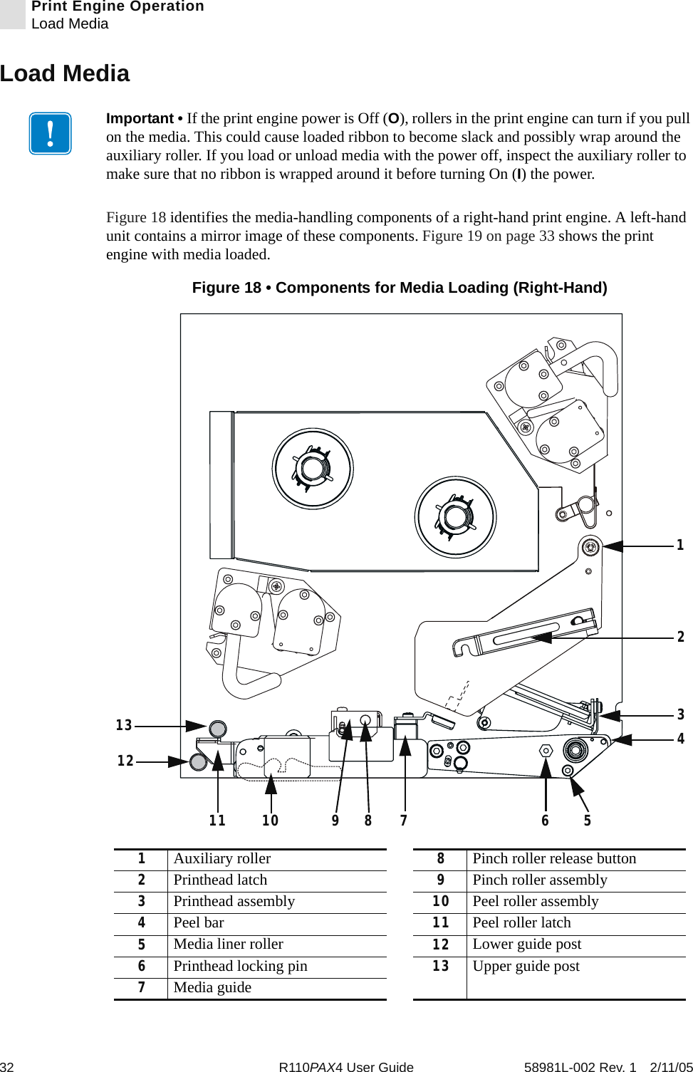
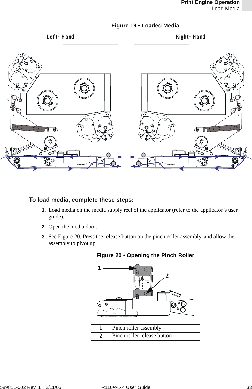
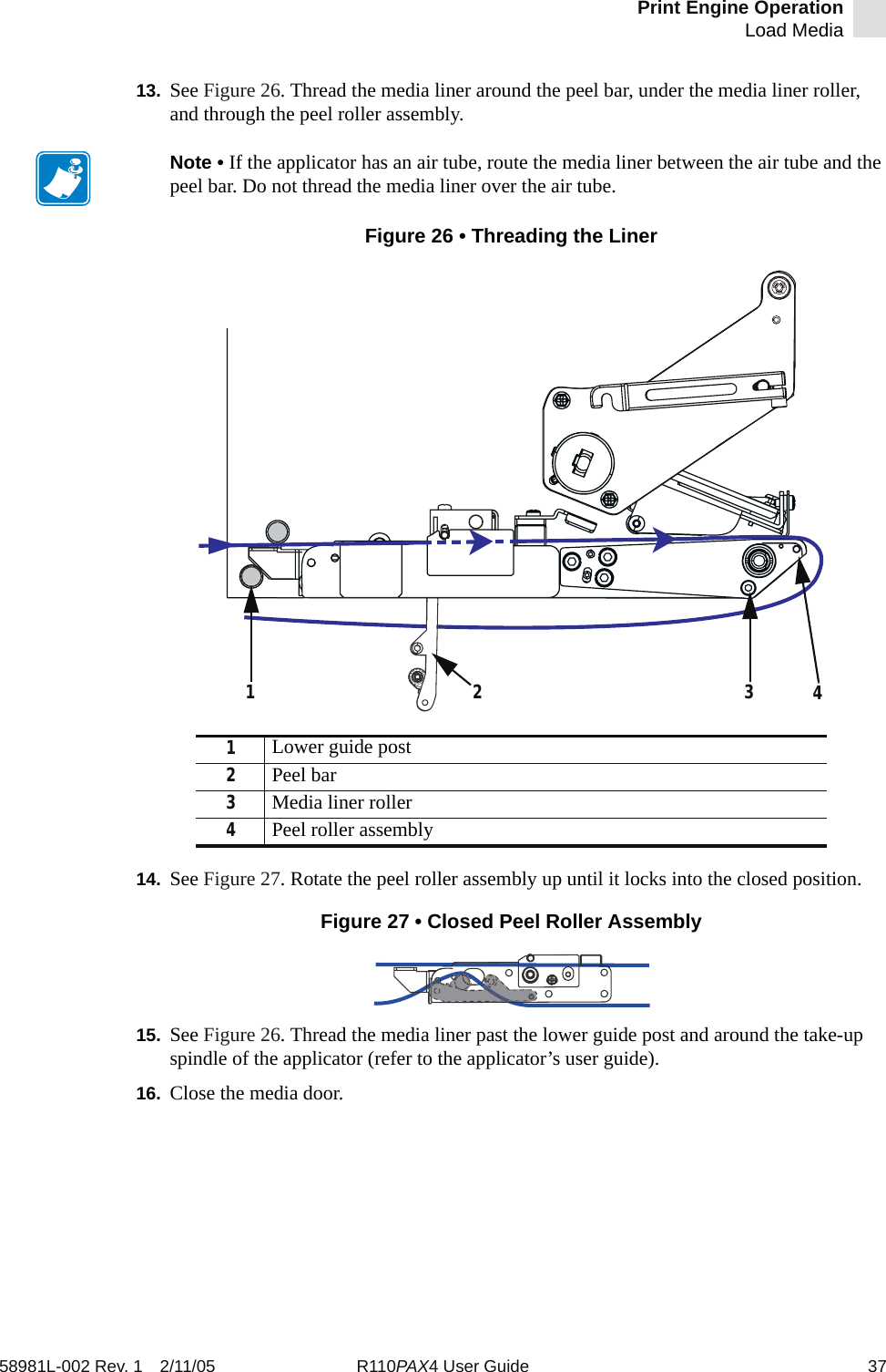
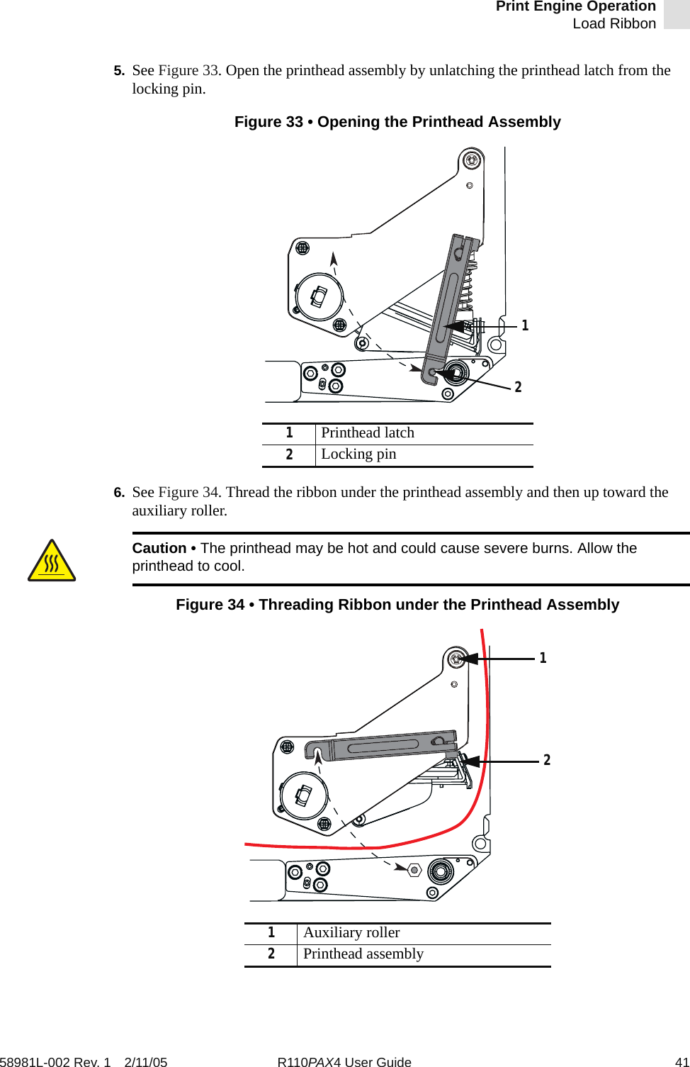
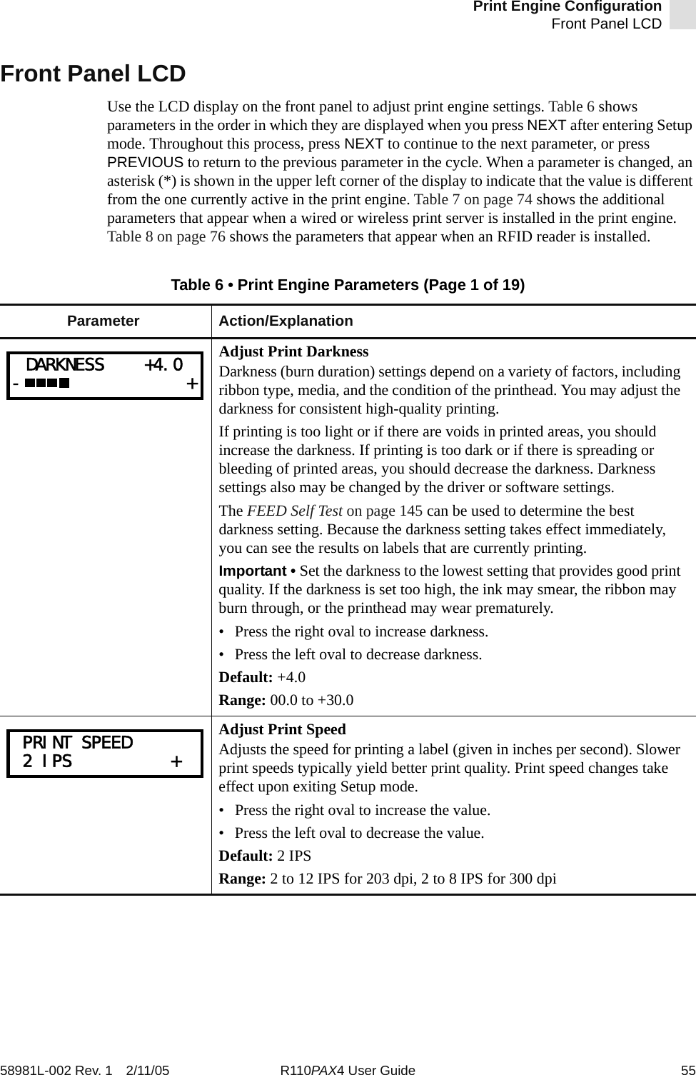
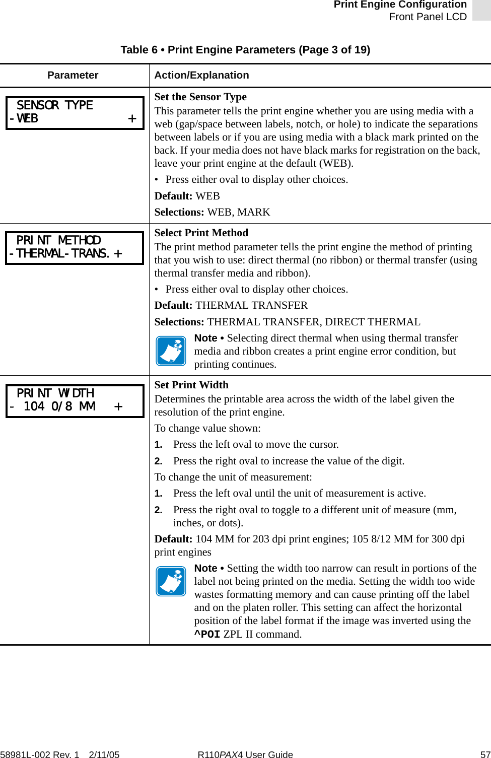
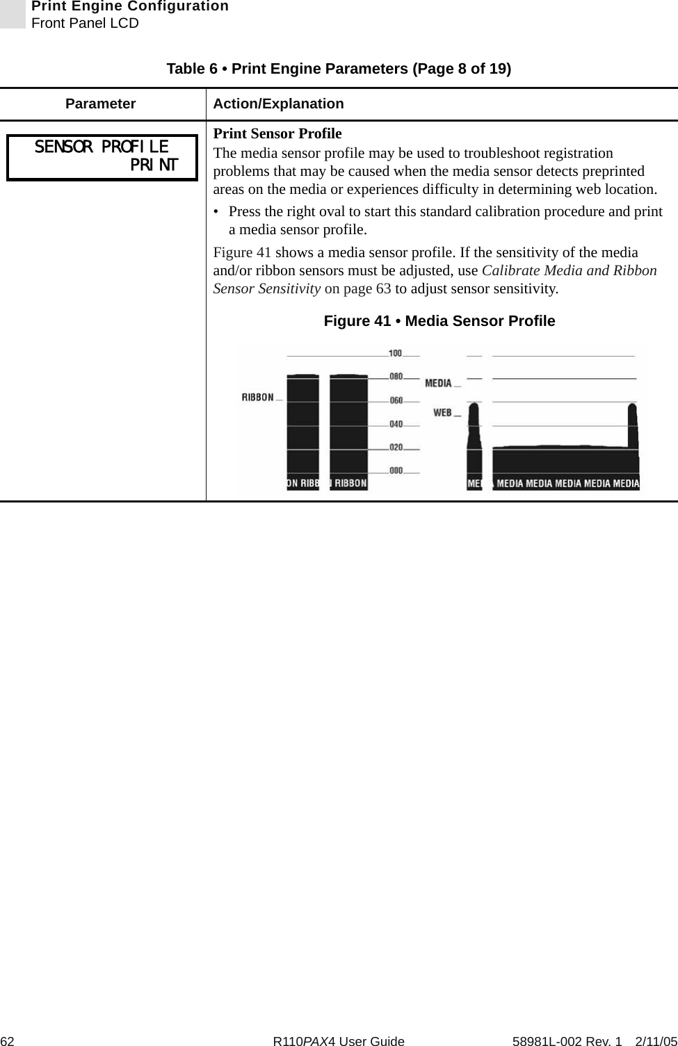
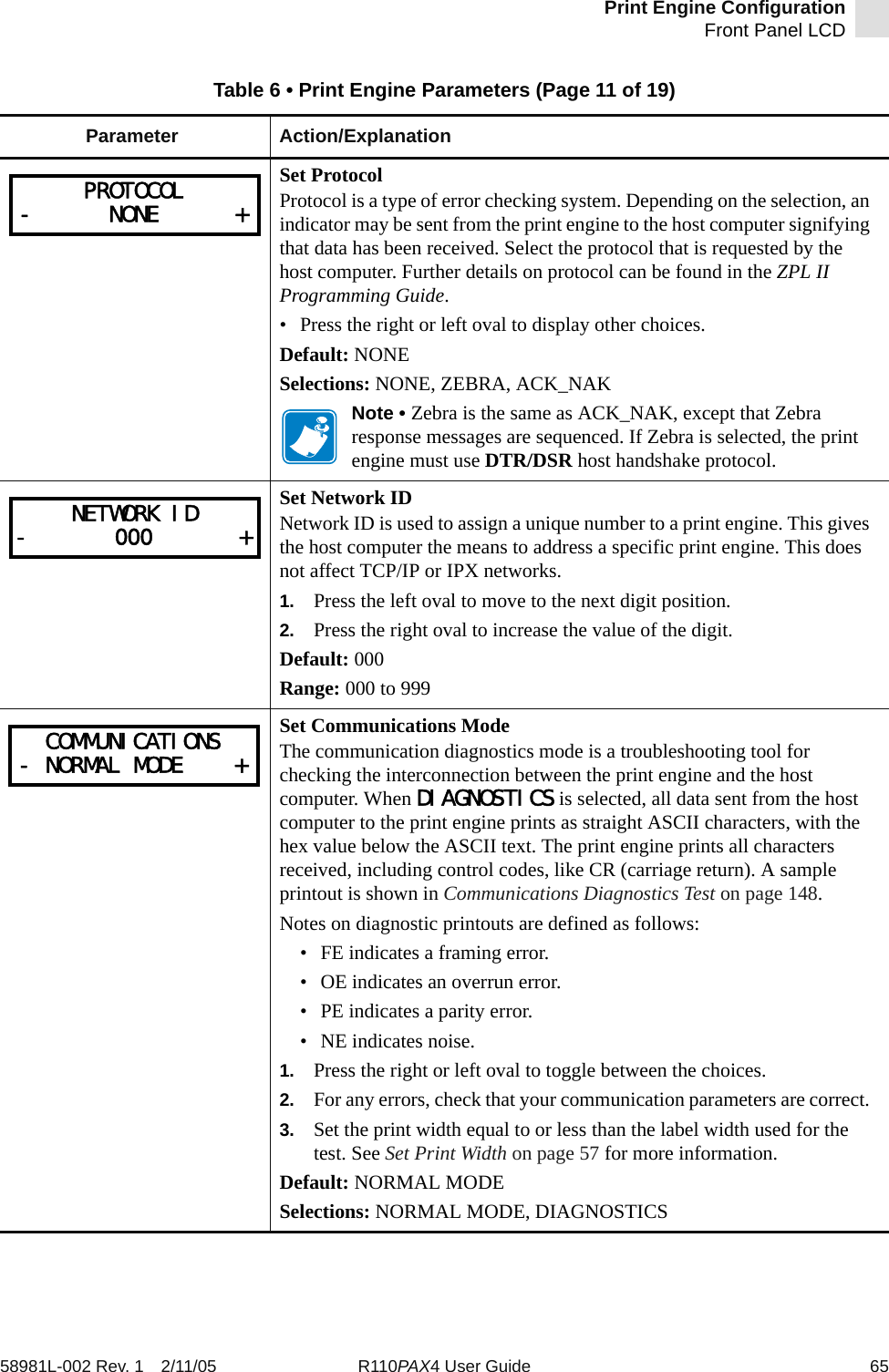
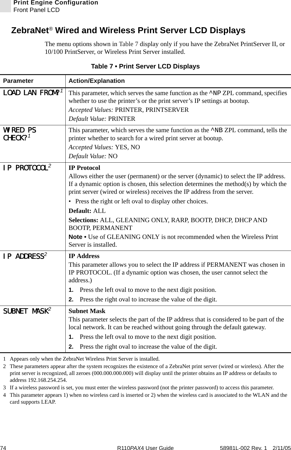
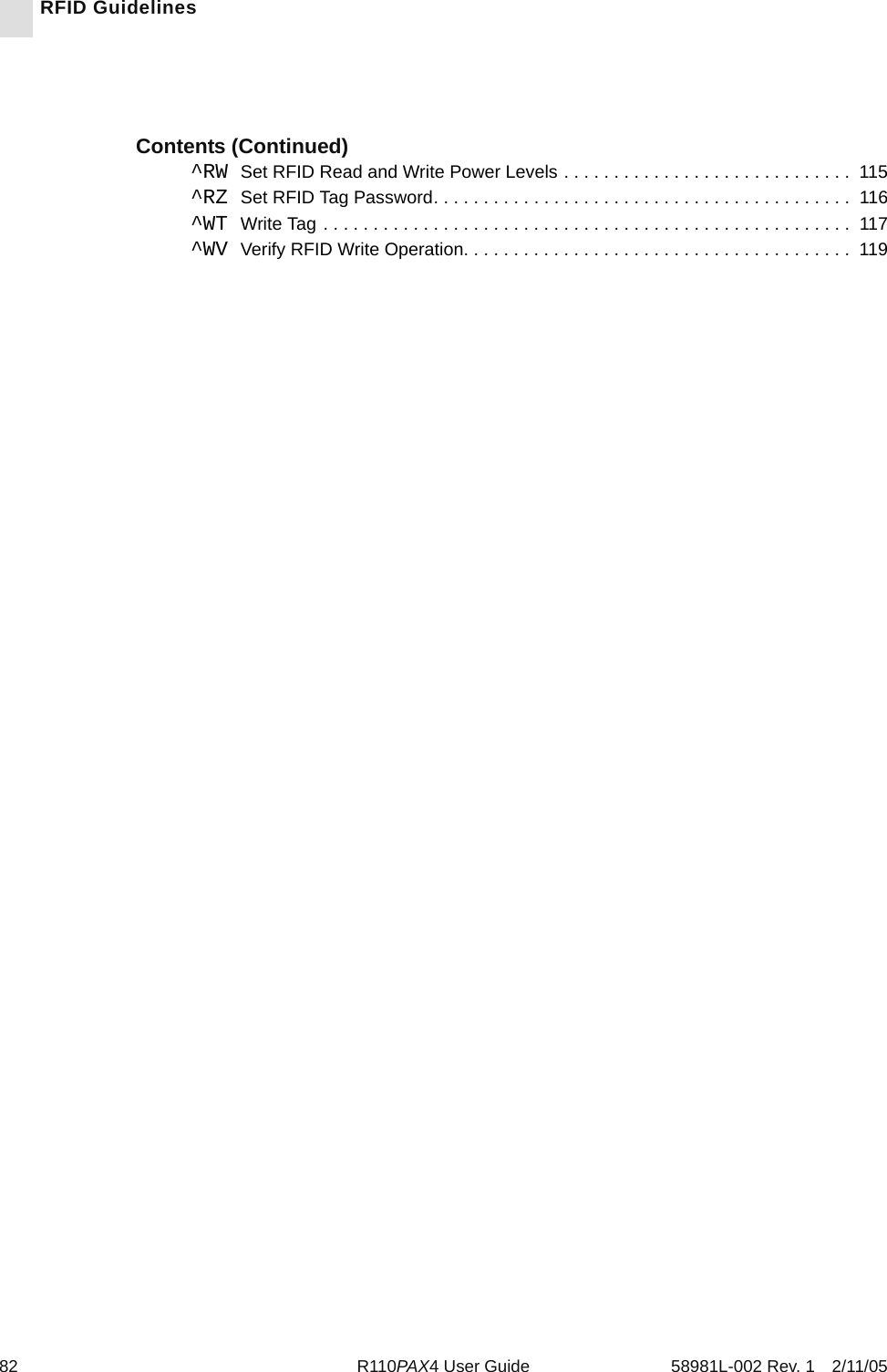
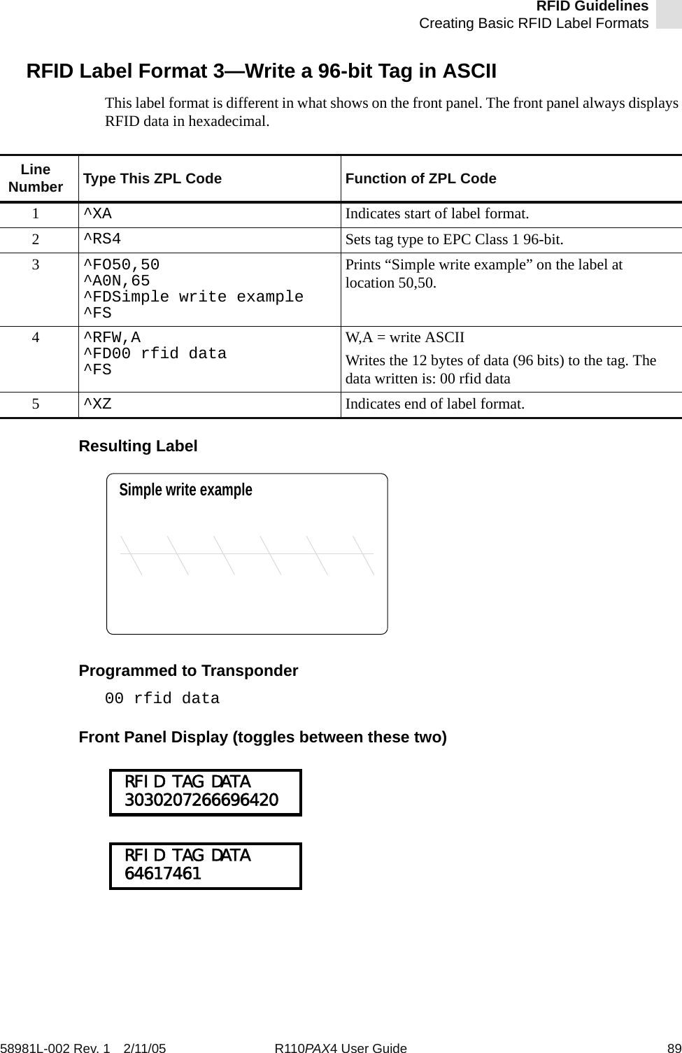
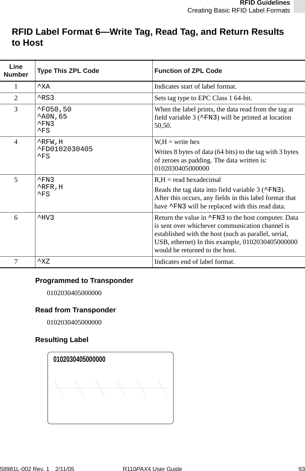
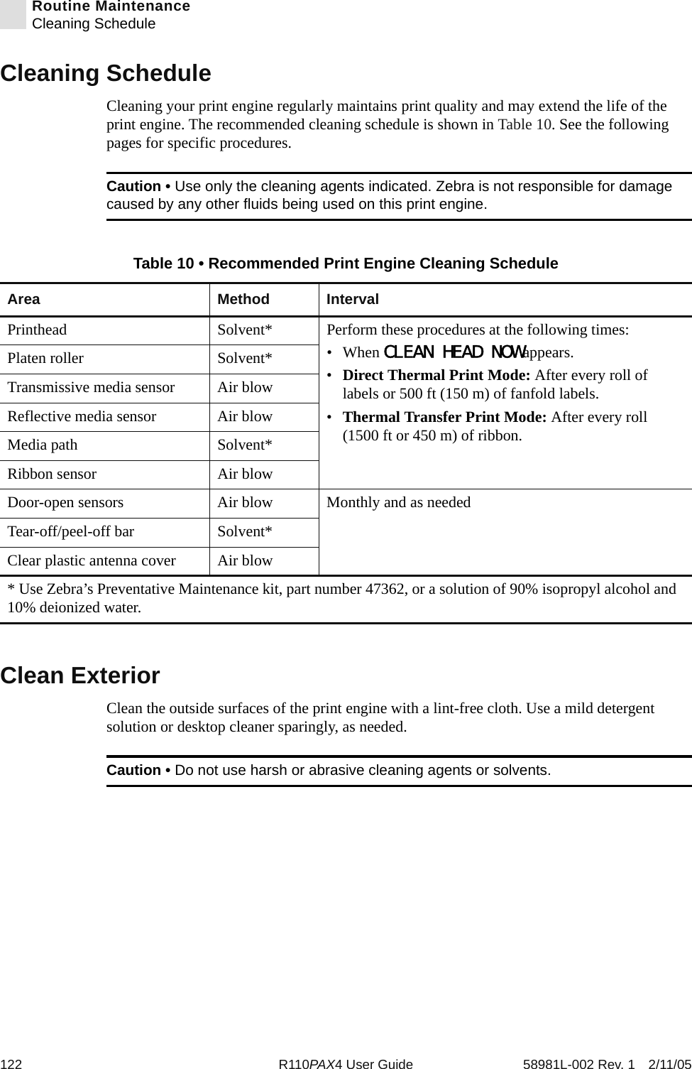
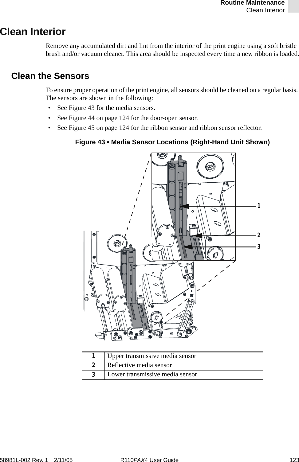
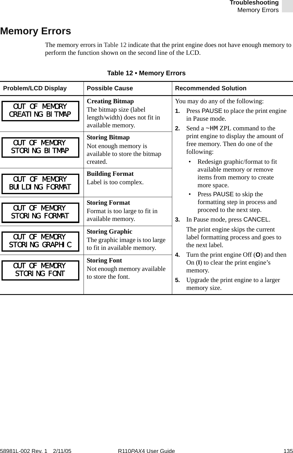
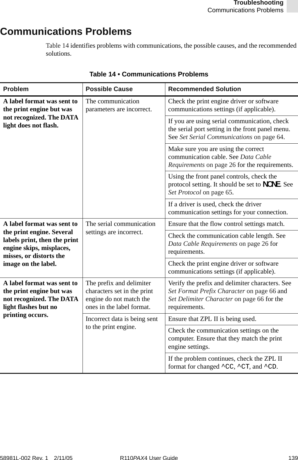
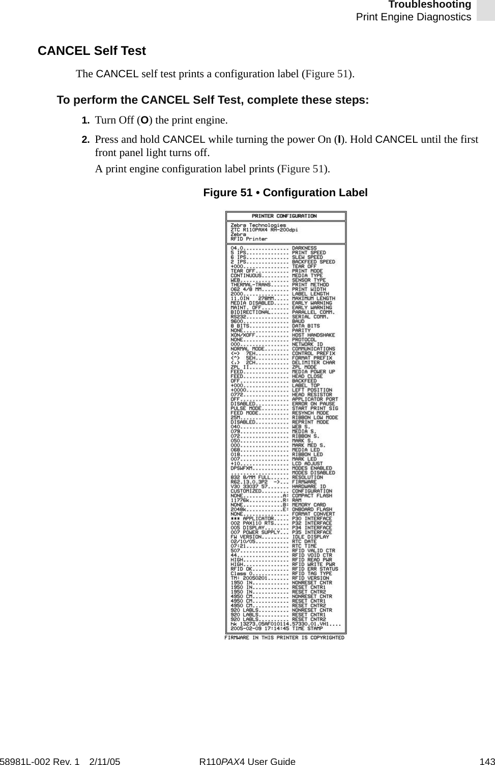
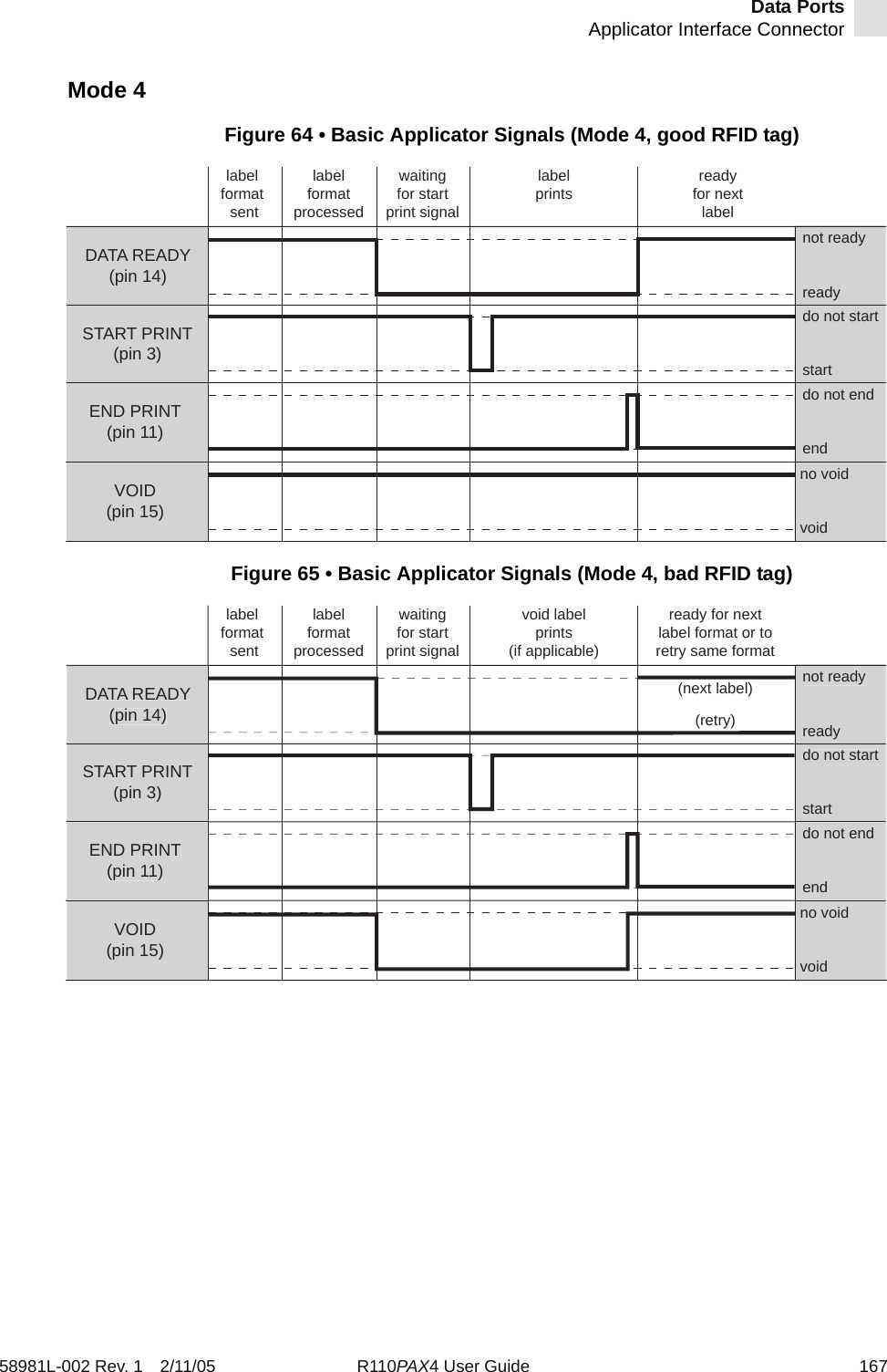
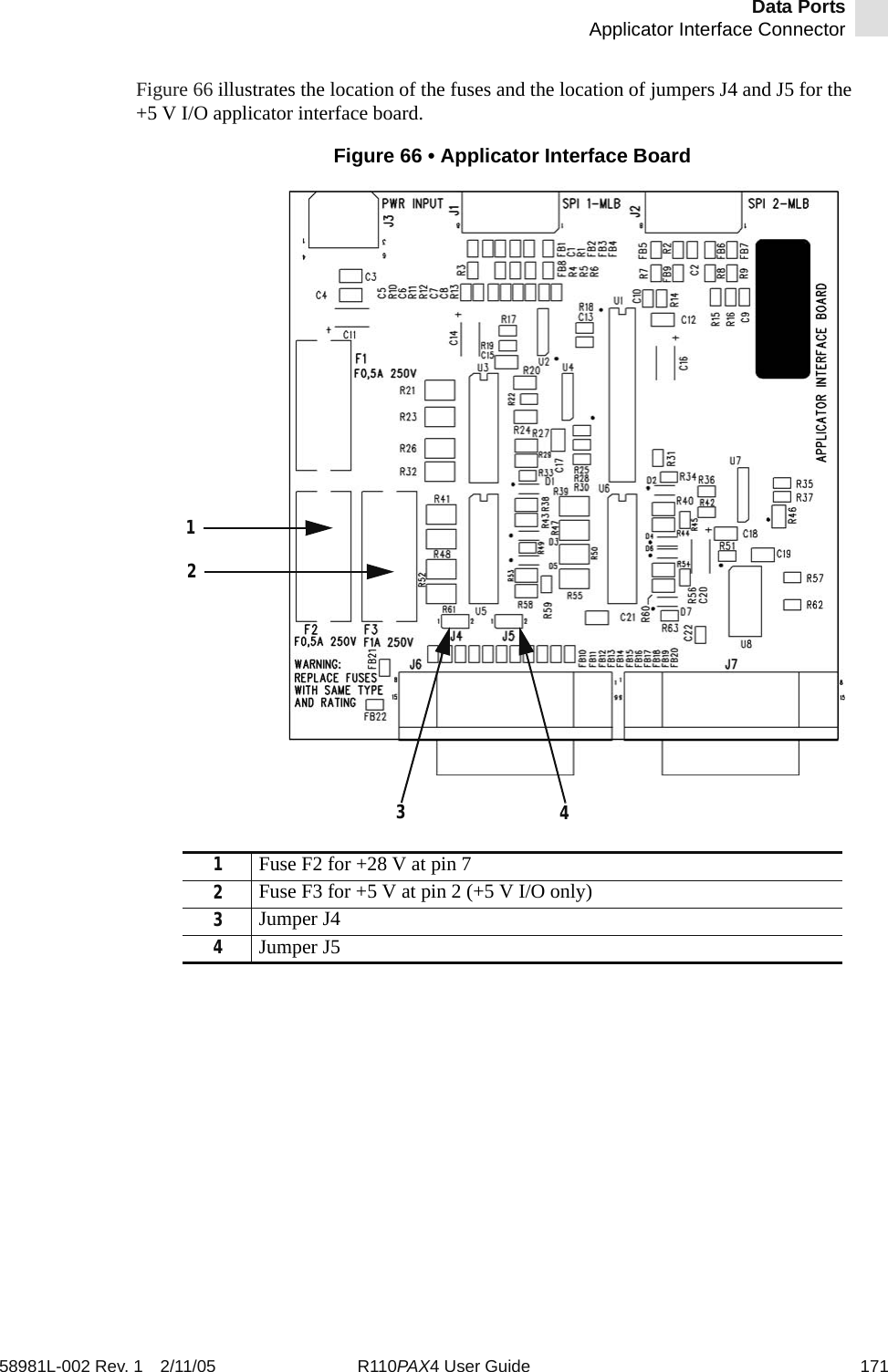
![RFID Guidelines^RS58981L-002 Rev. 1 2/11/05 R110PAX4 User Guide 111Example 1 • This example sets the printer to move the media to 800 dots from the top of the media [or label length minus 800 from the bottom (leading edge) of the media] and voids the rest of the media in case of an error. The printer will try to print two labels and then will pause if printing and encoding fail.^XA^RS,800,,2,P^FS^XZThe following illustration shows the resulting voided label. Note where the void starts. The media has been moved 800 dot rows from the top of the label (label length minus 800 dot rows from the bottom (leading edge) of a label) to bring the transponder into the effective area to read/write a tag. If the printer fails the operation, the rest of the media is voided.Top of labelStart of RFID operation800 dot rowsBottom of labelLabel length minus 800 dot rows](https://usermanual.wiki/Zebra-Technologies/RFID-M4E-01.Users-Manual-AX4-Part-2/User-Guide-566968-Page-81.png)
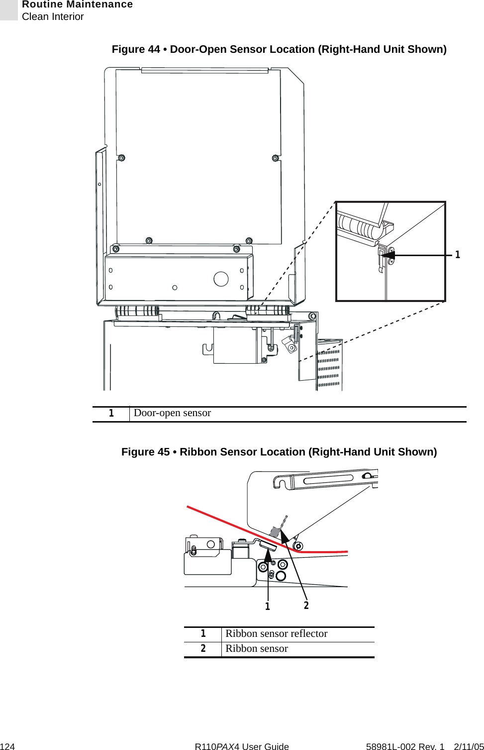
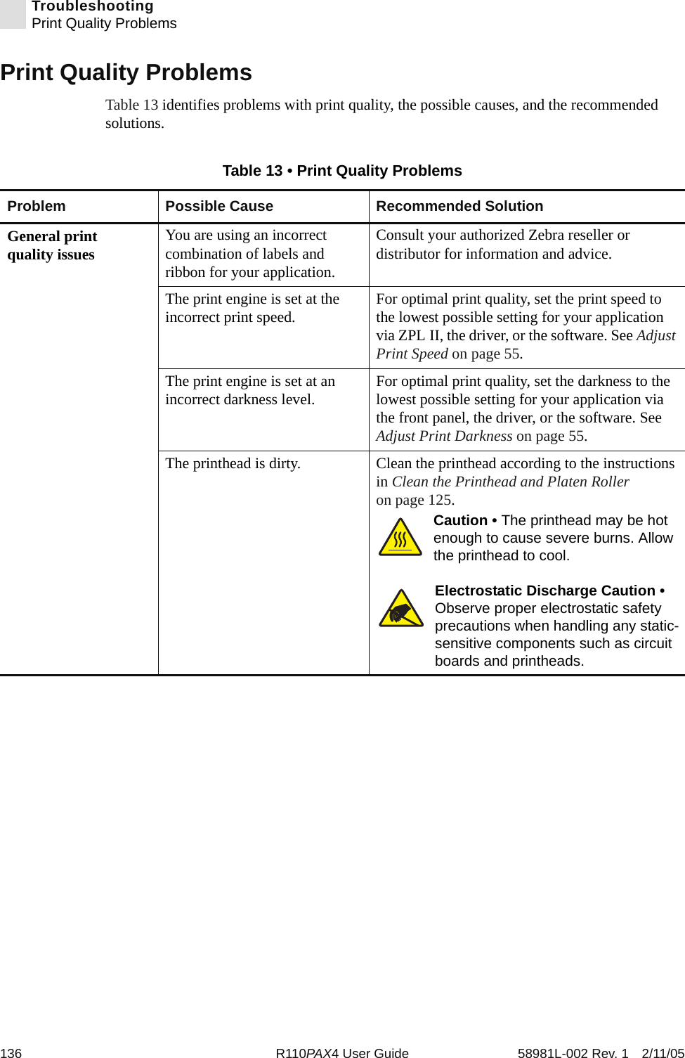
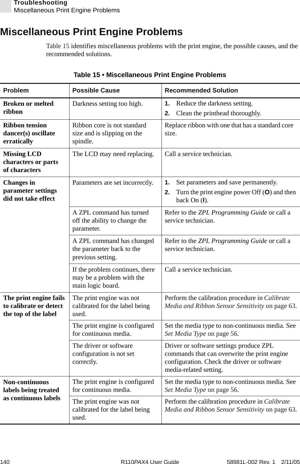
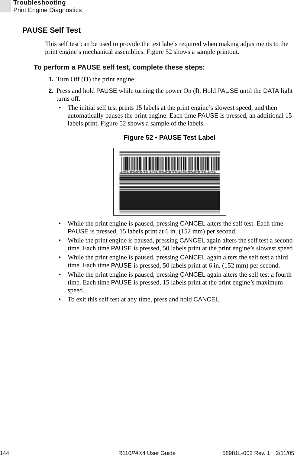
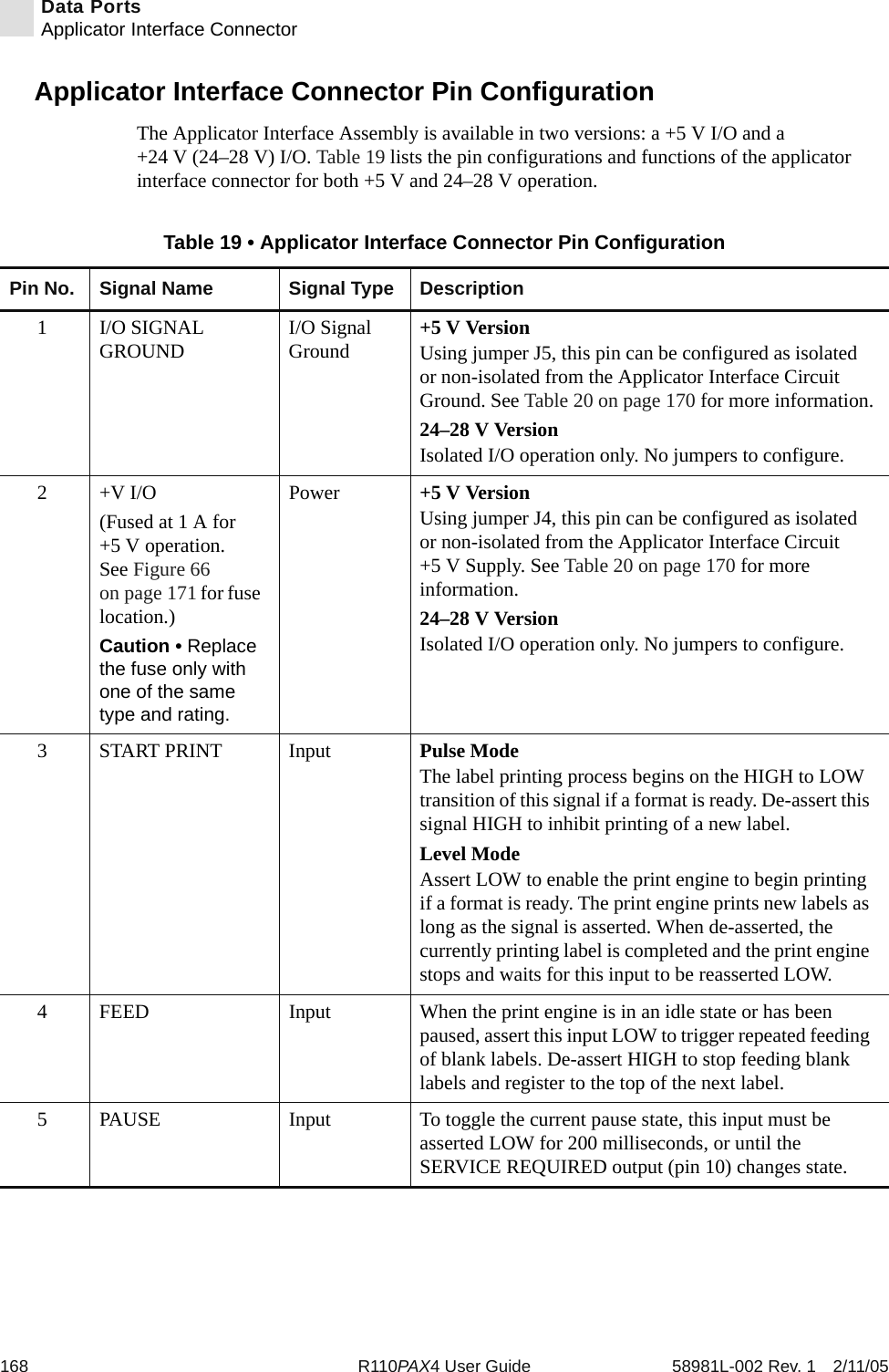
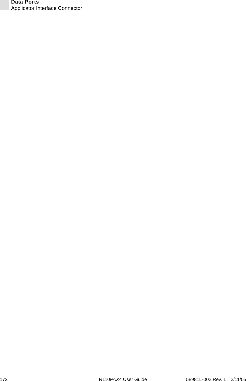
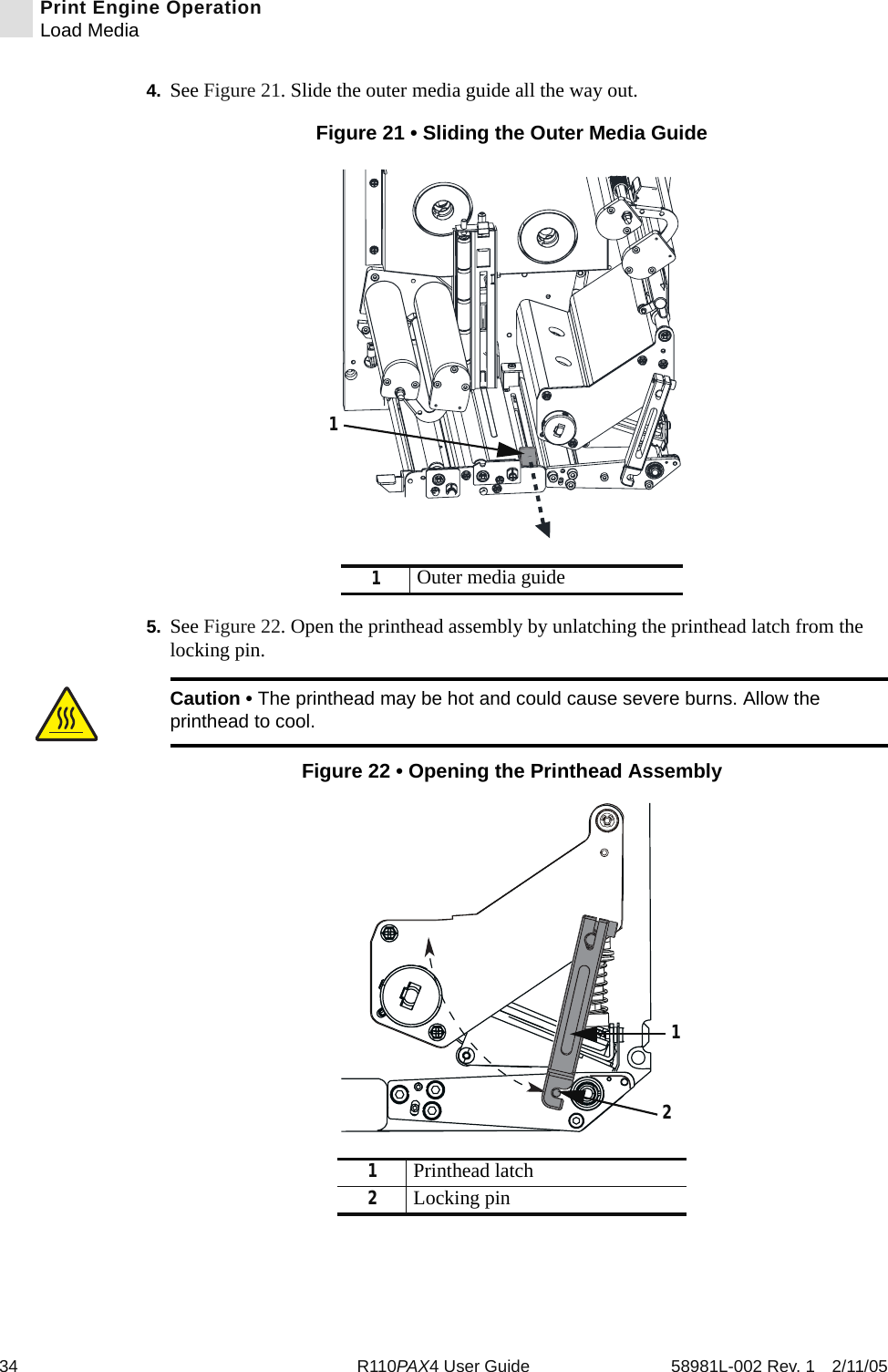
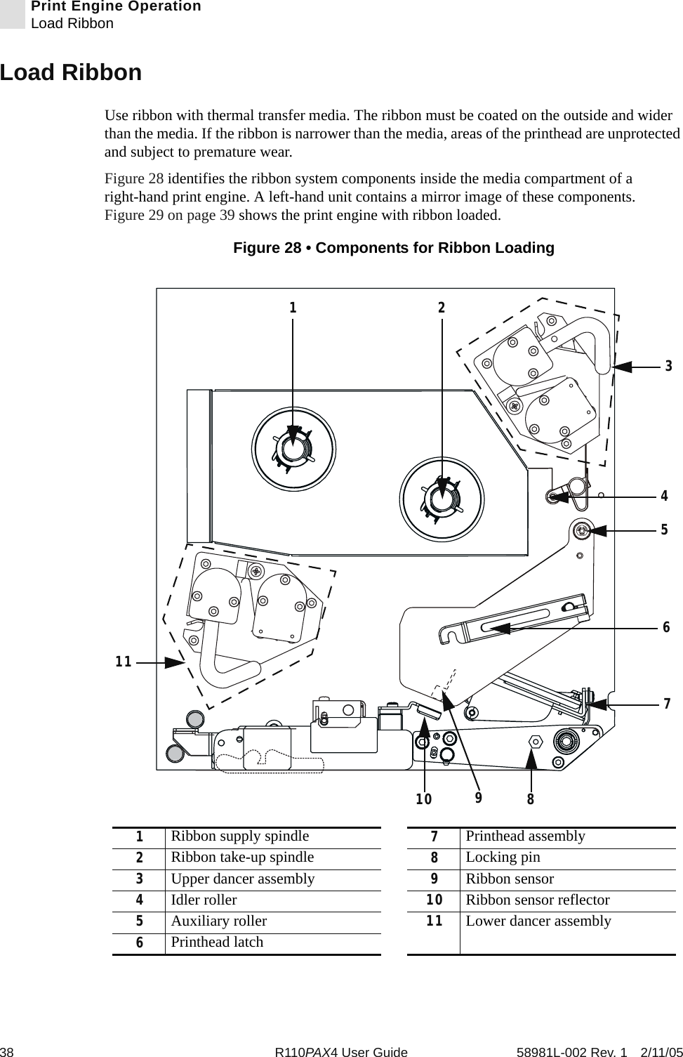
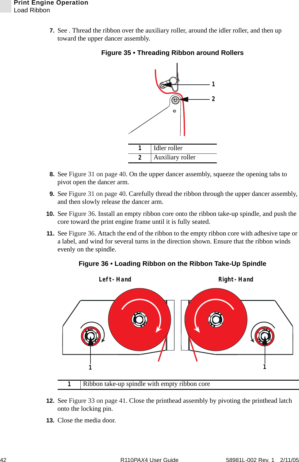
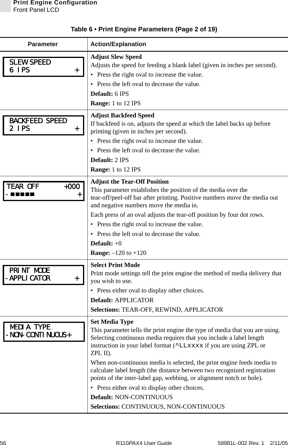
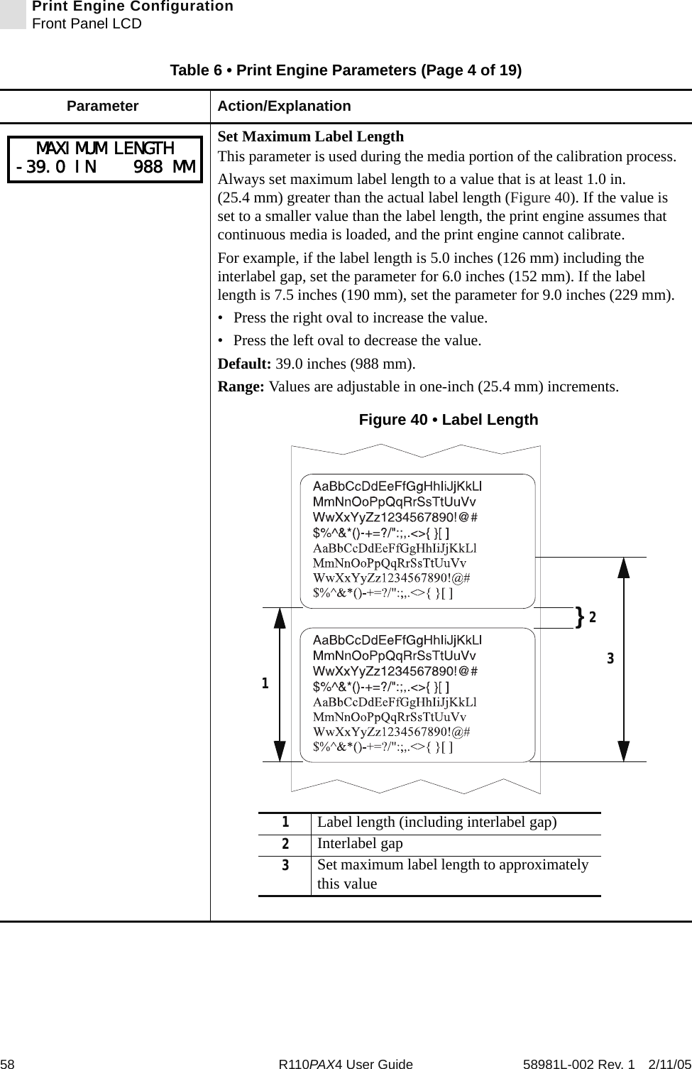
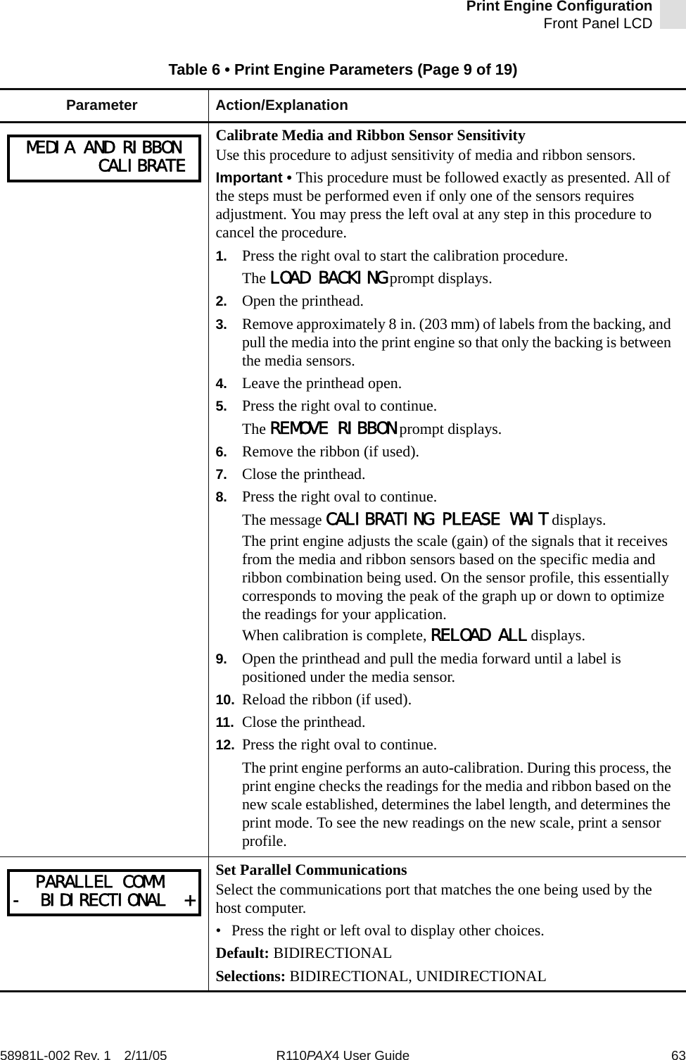
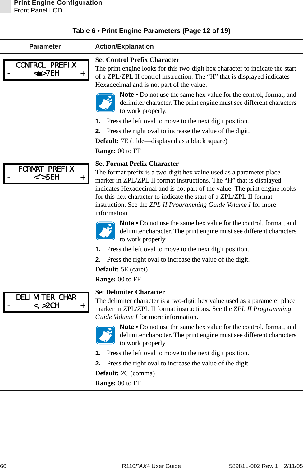
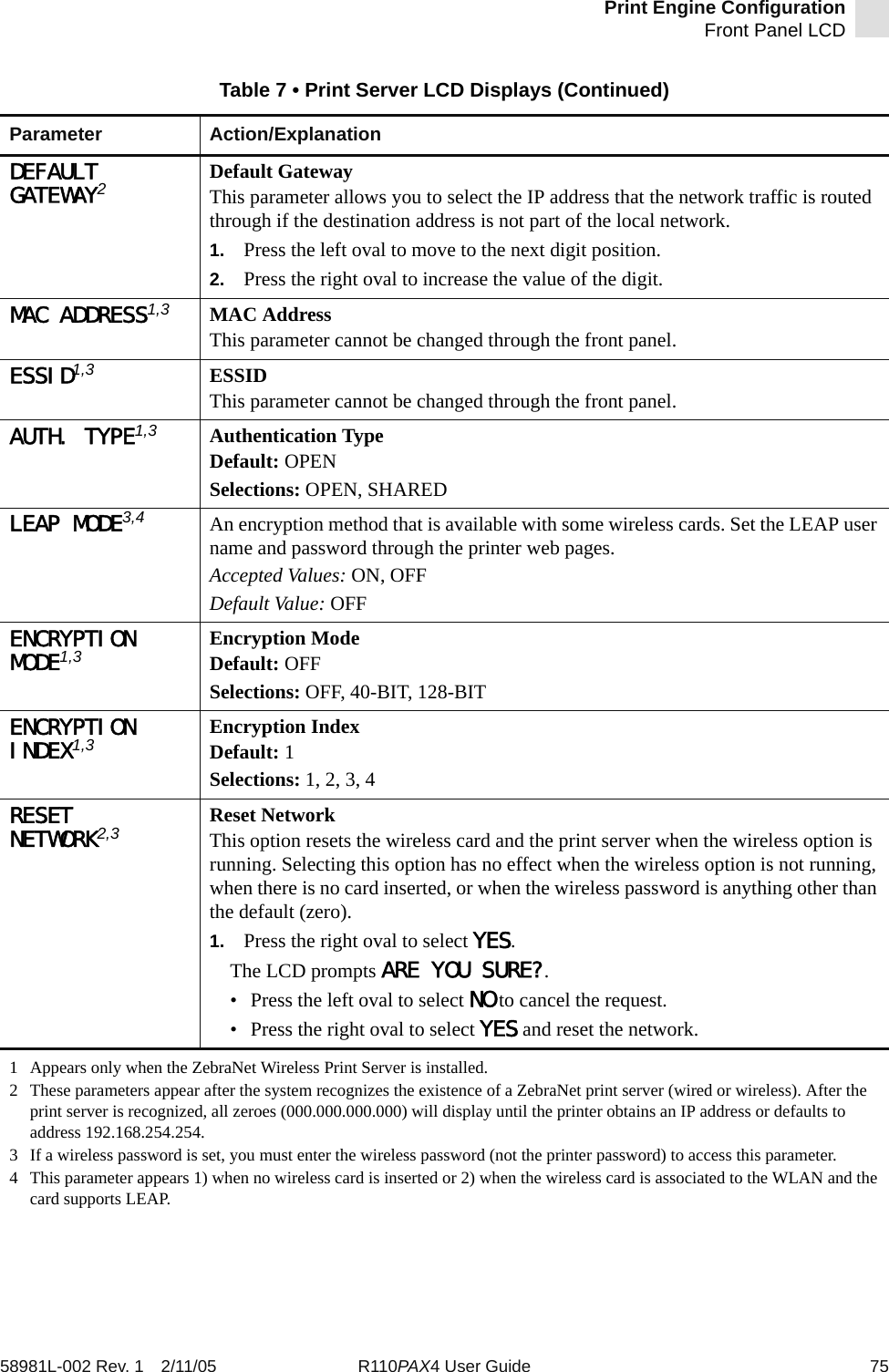
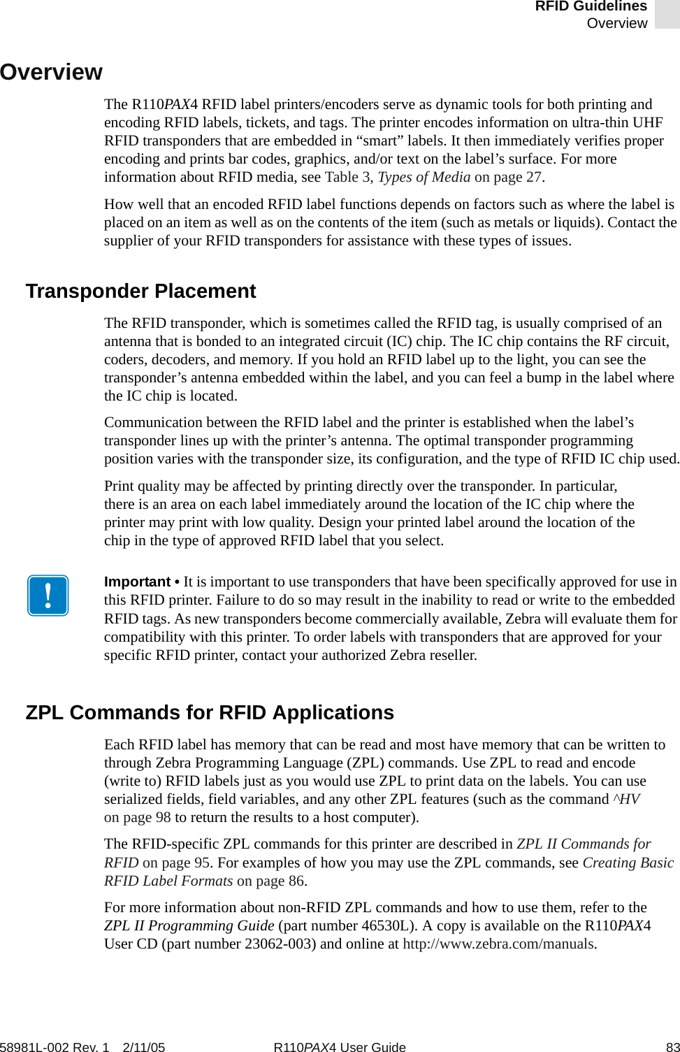
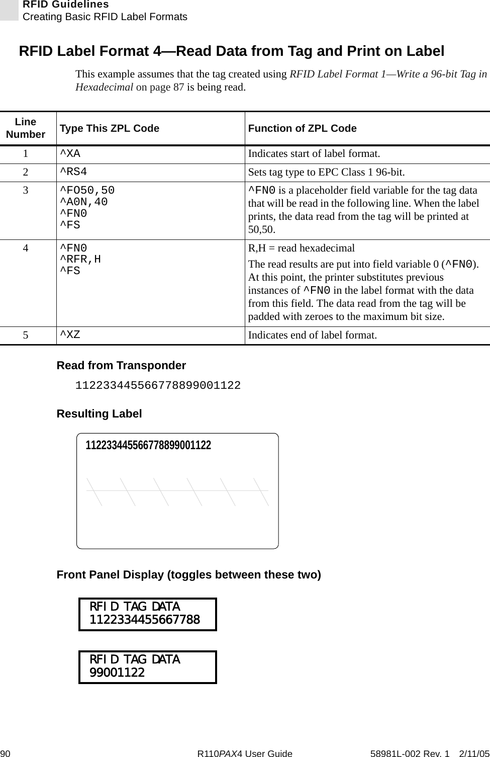
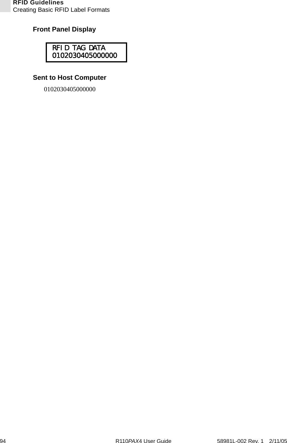
![112 R110PAX4 User Guide 58981L-002 Rev. 1 2/11/05RFID Guidelines^RSExample 2 • This example sets the printer to move the media to 800 dots from the top of the media [or label length - 500 from the bottom (leading edge) of the media] and prints “VOID” 500 dots in vertical length (Y axis) in case of an error.^XA^RS,800,500,2,P^FS^XZThe following illustration shows the resulting voided label. Note where the void starts. The media has been moved 800 dot rows from the top of the label [label length minus 800 dot rows from the bottom (leading edge) of a label] to bring the transponder into the effective area to read/write a tag. If the printer fails the operation, an area that is 500 dot rows of the media is voided instead of the entire rest of the media.Top of labelStart of RFID operation800 dot rowsBottom of labelLabel length minus 800 dot rows500 dot rows](https://usermanual.wiki/Zebra-Technologies/RFID-M4E-01.Users-Manual-AX4-Part-2/User-Guide-566968-Page-82.png)
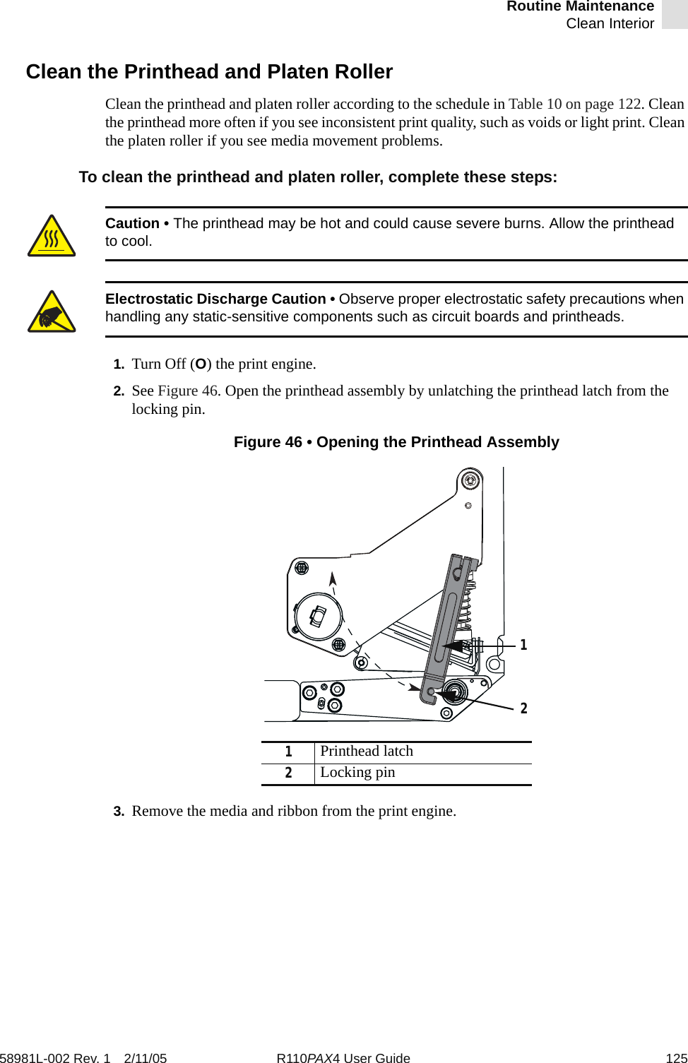
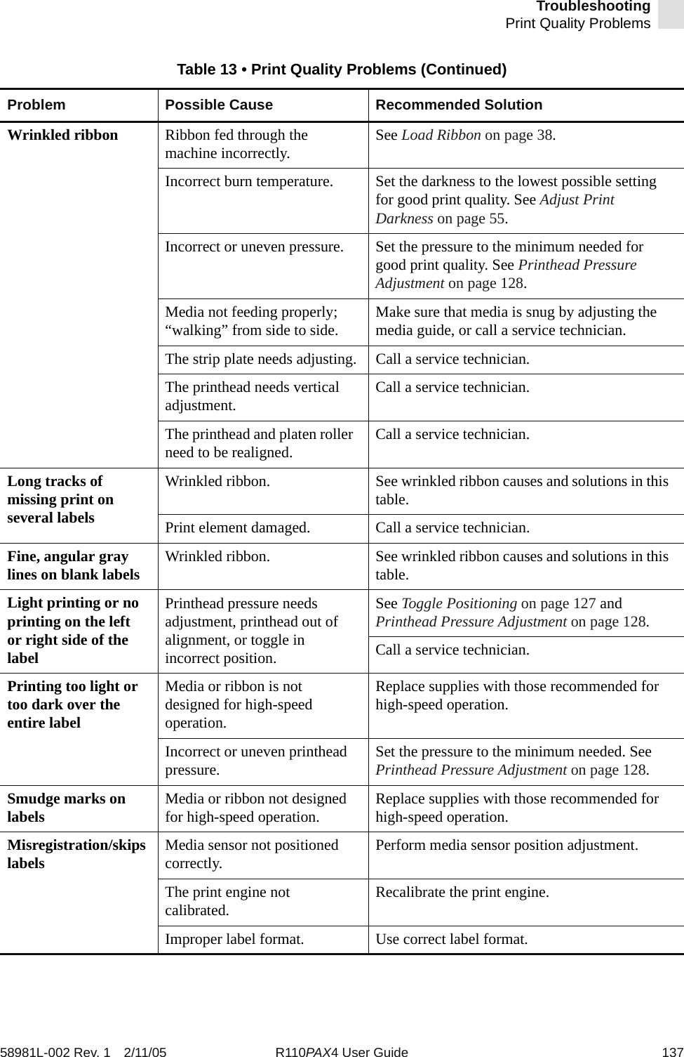
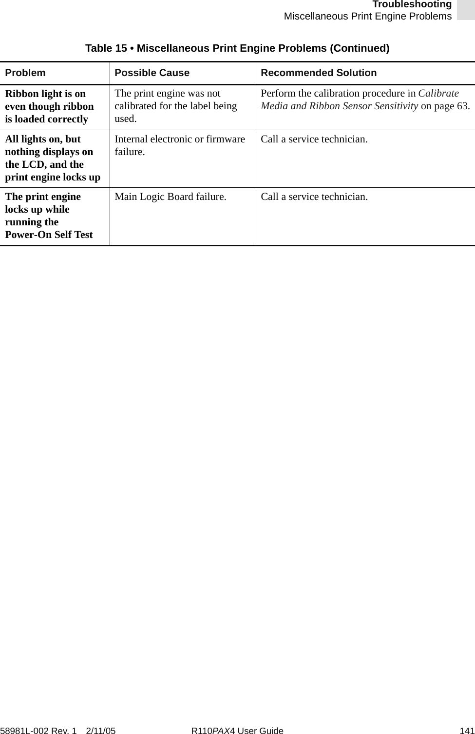
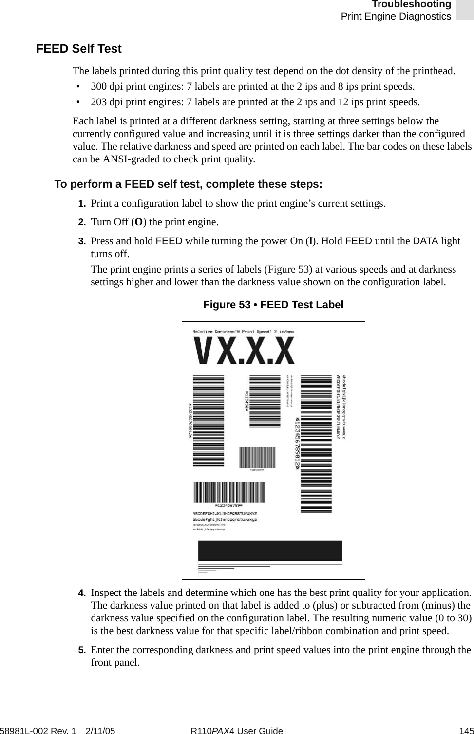
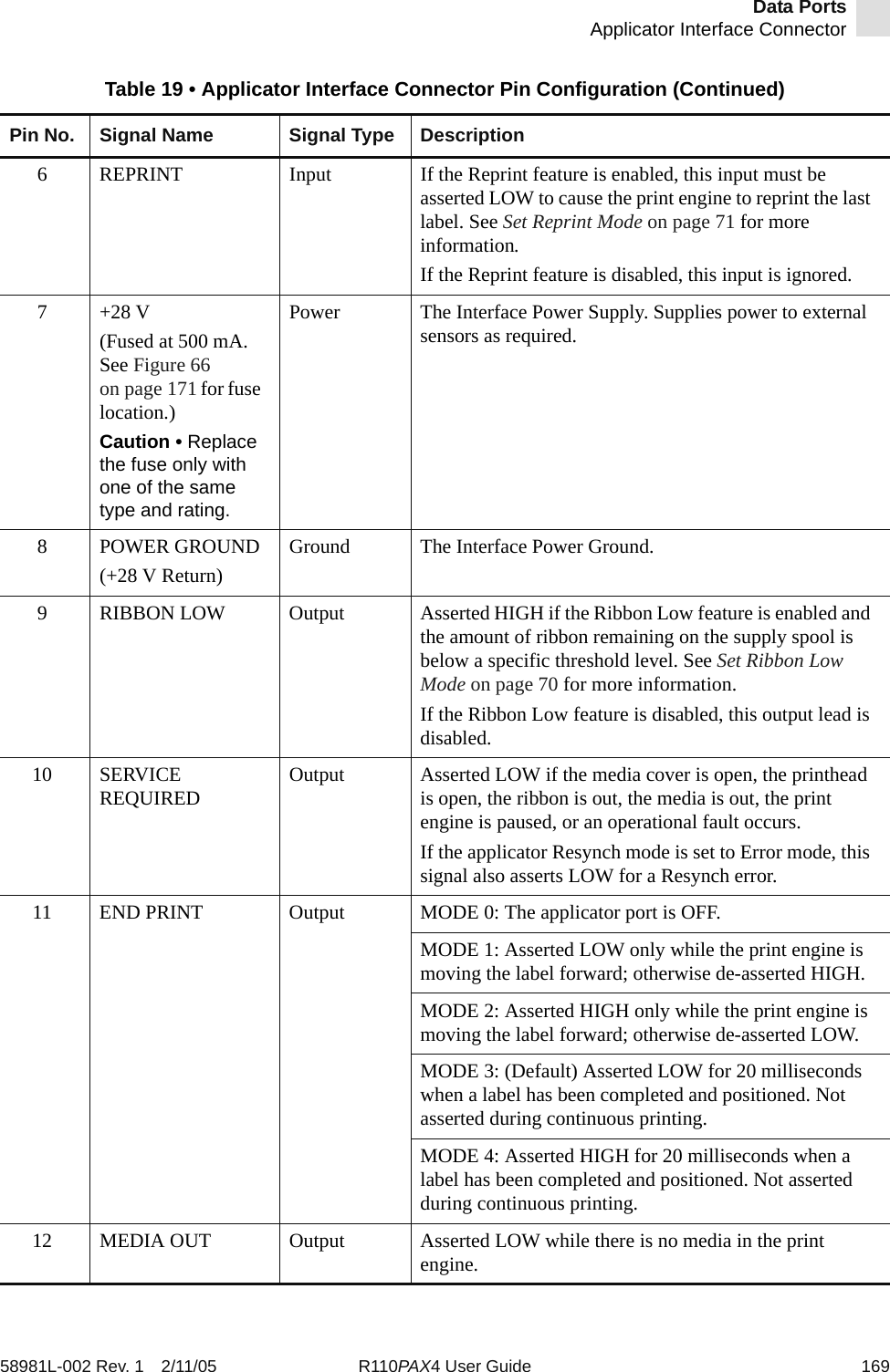
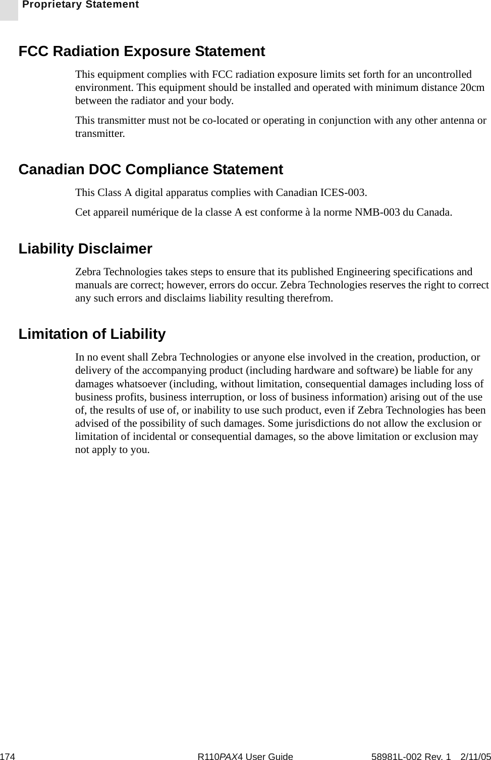
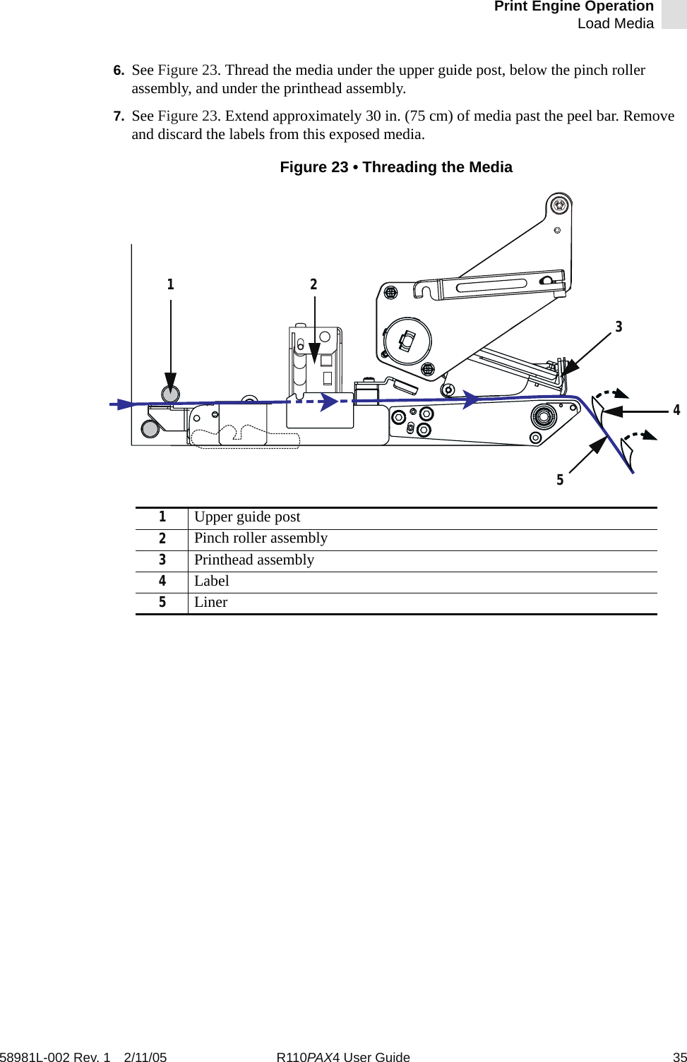
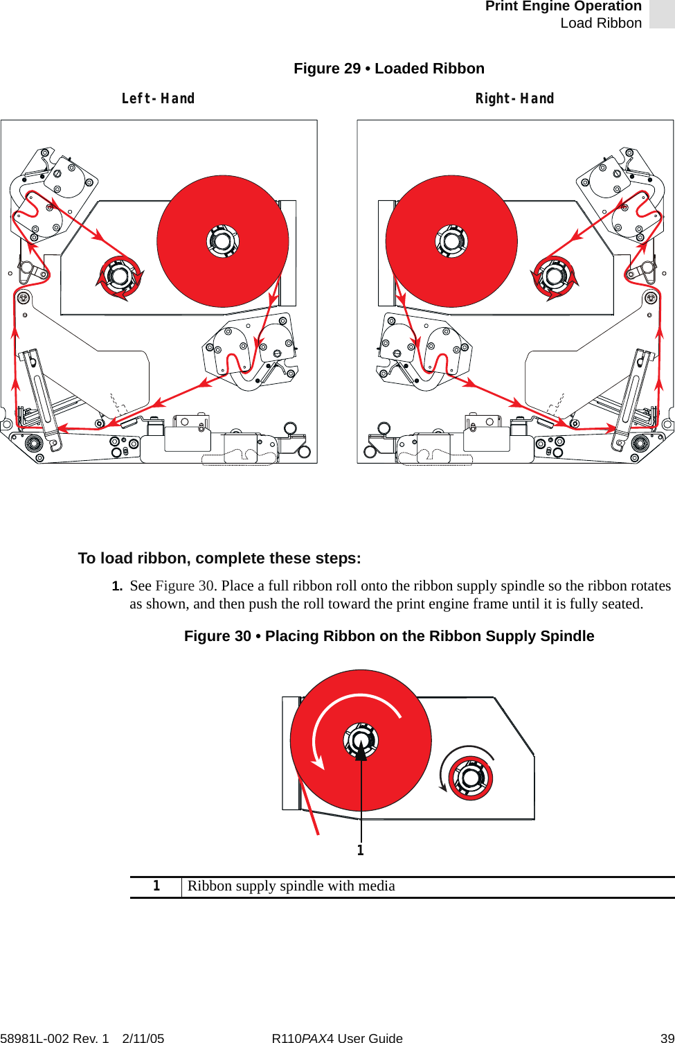
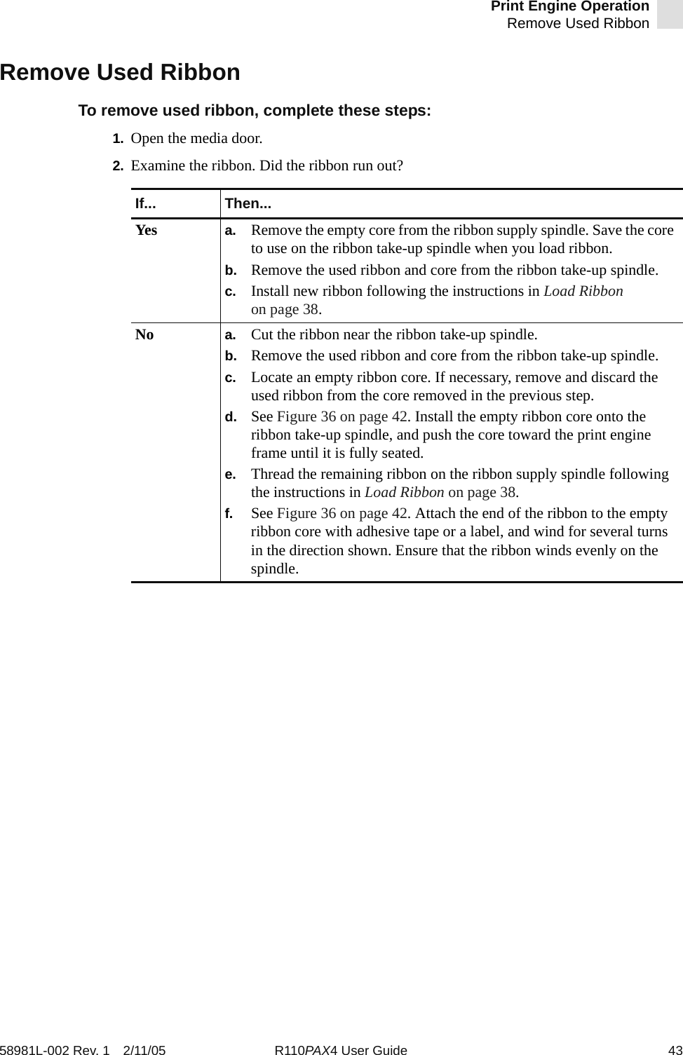
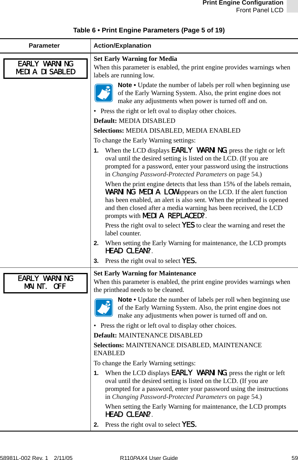
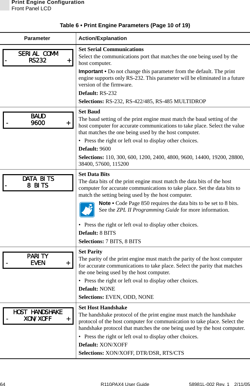
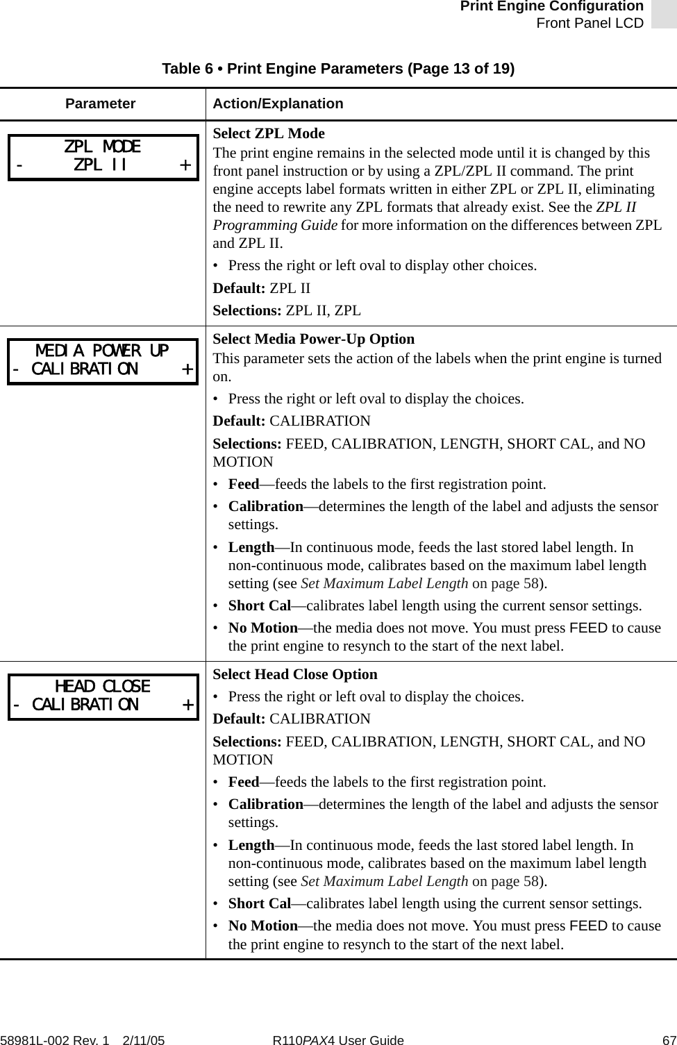
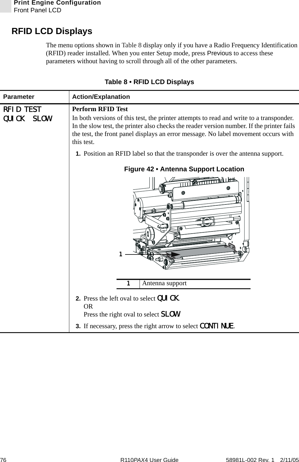
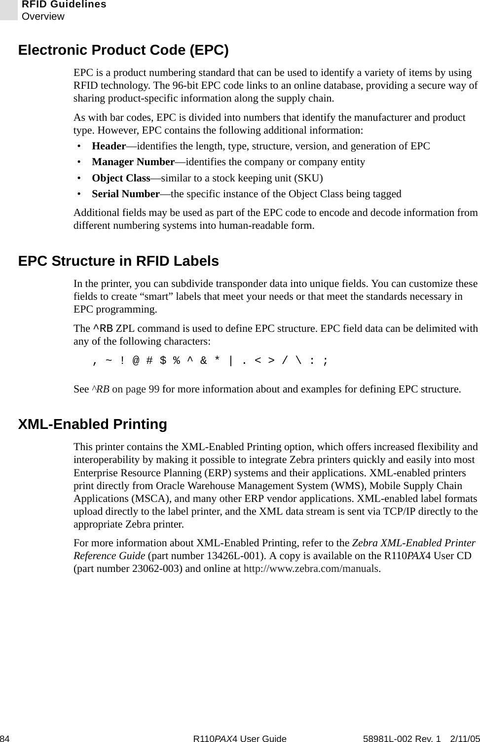
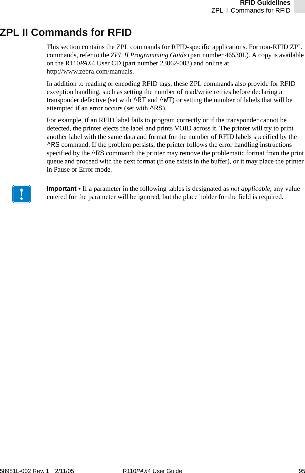
![118 R110PAX4 User Guide 58981L-002 Rev. 1 2/11/05RFID Guidelines^WTf= data format Accepted values:•0 (ASCII)• 1 (Hexadecimal)Default value: 0v= verify valid data Used only for Alien Class 1 tags, which have preprogrammed data in them. This parameter flags whether the preprogrammed data is verified. (Same function as the ^WV command)Default value: NAccepted values:• N (Do not verify)• Y (Verify valid data [Hex A5A5 in the first two bytes] before writing)Parameters DetailsExample • This sample encodes data “RFIDRFID” and will try writing up to five times, if necessary.^XA^WT,5^FDRFIDRFID^FS^XZ](https://usermanual.wiki/Zebra-Technologies/RFID-M4E-01.Users-Manual-AX4-Part-2/User-Guide-566968-Page-88.png)