Zebra Technologies RFID-M4E-01 Multiprotocol RFID Encoder User Manual Technical Writer II
Zebra Technologies Corporation Multiprotocol RFID Encoder Technical Writer II
UserManual.wiki
>
Zebra Technologies
>
RFID-M4E-01 User Manual
>
Users Manual R4M Part 2
Contents
1.
Users Manual AX4 Part 1
2.
Users Manual AX4 Part 2
3.
Users Manual R4M Part 1
4.
Users Manual R4M Part 2
5.
Users Manual R110
6.
New Users Manual
7.
New Users Manual PCII
Users Manual R4M Part 2
Navigation menu
Upload a User Manual
Namespaces
Wiki Guide
HTML
PDF
Info
Views
User Manual
Discussion / Help
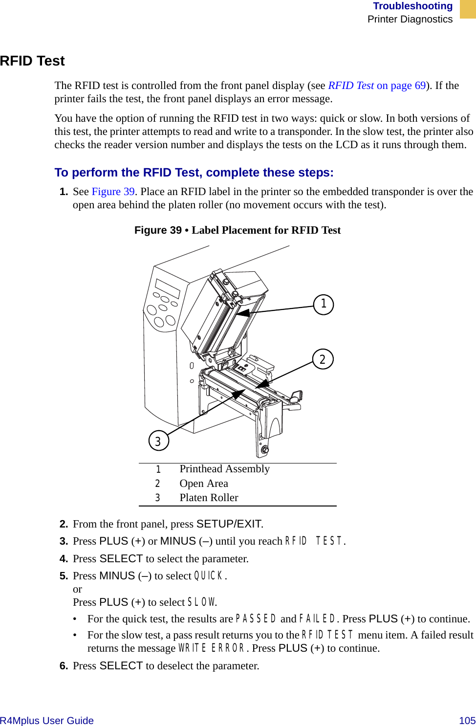
Navigation

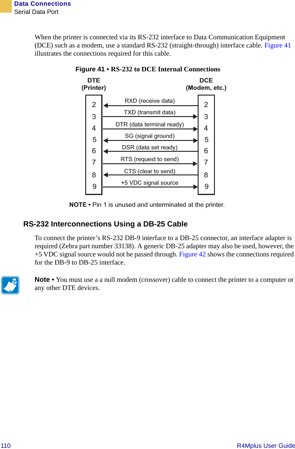
![74 R4Mplus User GuideRFID GuidelinesZPL II Commands for RFID^WTWrite TagDescription The ^WT command allows you to program the current RFID tag.Format ^WTb,r,m,w,f,vTable 8 identifies the parameters for this format.Note • Check the amount of data memory available for the tag that you will be using. If more is sent than the memory can hold, the data will be truncated.Table 8 • ^WT ParametersParameters Detailsb = block number* Accepted values: 0 to n, where n is the maximum number of blocks for the tag.Default value: 0r = number of retries Accepted values: 0 to 10Default value: 0m = motion Accepted values: • 0 (Feed label after writing.)• 1 (No Feed after writing. Other ZPL may cause a feed.)Default value: 0w = write protect Accepted values: • 0 (Not write protected.) • 1 (Write protect.)Default value: 0f = data format Accepted values: • 0 (ASCII)• 1 (Hexadecimal)Default value: 0v = verify valid data Default value: yAccepted values: • n (Do not verify)• y (Verify valid data [Hex A5A5 in the first two bytes] before writing)*Not applicable for R4Mplus](https://usermanual.wiki/Zebra-Technologies/RFID-M4E-01.Users-Manual-R4M-Part-2/User-Guide-566970-Page-4.png)
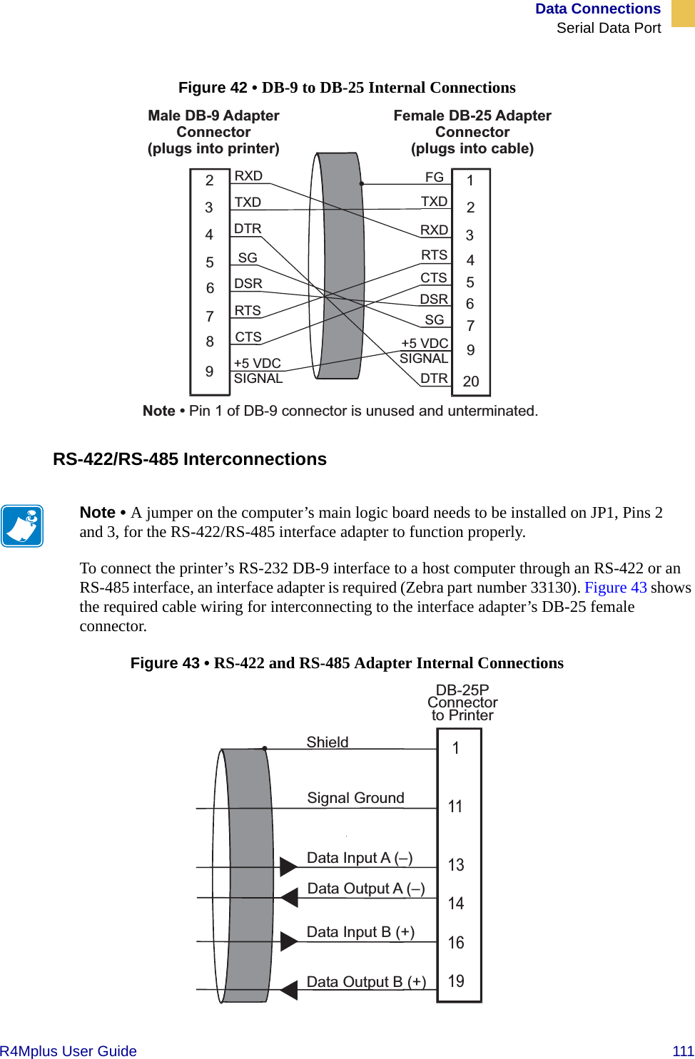
![RFID GuidelinesZPL II Commands for RFIDR4Mplus User Guide 81Example • This example sets the printer to move the media to 800 dots from the top of the media [or label length minus 800 from the bottom (leading edge) of the media] and voids the rest of the media in case of an error. The printer will try to print two labels, then will pause the printer if printing and encoding fail.^XA^RS,800,,2,P^FS^XZFigure 31 shows the resulting voided label. Note where the void starts. The media has been moved 800 dot rows from the top of the label (label length minus 800 dot rows from the bottom (leading edge) of a label) to bring the transponder into the effective area to read/write a tag. If the printer fails the operation, the rest of the media is voided.Figure 31 • Sample Voided Label 1Top of labelStart of RFID operation800 dot rowsBottom of labelLabel length minus 800 dot rows](https://usermanual.wiki/Zebra-Technologies/RFID-M4E-01.Users-Manual-R4M-Part-2/User-Guide-566970-Page-11.png)
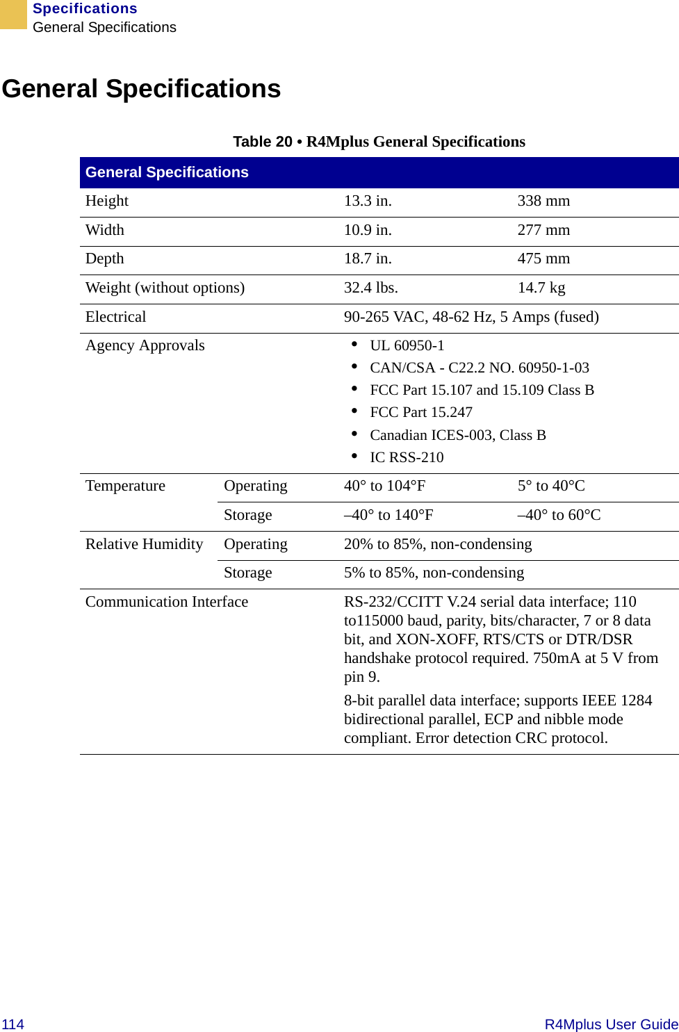
![82 R4Mplus User GuideRFID GuidelinesZPL II Commands for RFIDExample • This example sets the printer to move the media to 800 dots from the top of the media [or label length - 500 from the bottom (leading edge) of the media] and prints “void” 500 dots in vertical length (Y axis) in case of an error.^XA^RS,800,500,2,P^FS^XZFigure 32 shows the resulting voided label. Note where the void starts. The media has been moved 800 dot rows from the top of the label [label length minus 800 dot rows from the bottom (leading edge) of a label] to bring the transponder into the effective area to read/write a tag. If the printer fails the operation, an area that is 500 dot rows of the media is voided instead of the entire rest of the media as in Figure 31.Figure 32 • Sample Voided Label 2Top of labelStart of RFID operation800 dot rowsBottom of labelLabel length minus 800 dot rows500 dot rows](https://usermanual.wiki/Zebra-Technologies/RFID-M4E-01.Users-Manual-R4M-Part-2/User-Guide-566970-Page-12.png)