Zebra Technologies RFID-M4E-01 Multiprotocol RFID Encoder User Manual Technical Writer II
Zebra Technologies Corporation Multiprotocol RFID Encoder Technical Writer II
Contents
Users Manual R4M Part 2

R4Mplus User Guide 71
CHAPTER 5
RFID Guidelines
This chapter provides an overview of how RFID works and the ZPL commands used to create
RFID labels.
Contents
Overview. . . . . . . . . . . . . . . . . . . . . . . . . . . . . . . . . . . . . . . . . . . . . 72
Transponder Placement . . . . . . . . . . . . . . . . . . . . . . . . . . . . . . . . . 72
ZPL II Commands for RFID . . . . . . . . . . . . . . . . . . . . . . . . . . . . . . 73
Sample of RFID Programming . . . . . . . . . . . . . . . . . . . . . . . . . . . . 83

72 R4Mplus User Guide
RFID Guidelines
Overview
Overview
The R4Mplus “smart” label printer-encoder serves as a dynamic tool for both printing and
encoding RFID labels, tickets, and tags. The printer encodes information on ultra-thin UHF
RFID transponders embedded in “smart” labels. It then immediately verifies proper encoding
and prints bar codes, graphics, and/or text on the label’s surface. For more information about
RFID media, see RFID “Smart” Labels on page 17.
Function of an encoded “smart” label depends on factors such as where the label is placed on
an item as well as on the contents of the item (such as metals or liquids). Contact the supplier
of your RFID reader for assistance with these types of issues.
Transponder Placement
Communication between the “smart” label and the printer is established when the transponder
lines up with the printer’s antenna. The optimal transponder position varies with the
transponder size, its configuration, and the type of RFID IC chip used.
Print quality may be affected by printing directly over the transponder. In particular, there is an
area on each label immediately around the location of the IC chip where the printer may print
with low quality. Design your printed label around the location of the chip in the type of
approved “smart” label that you select. For the list of approved transponders and related
placement specifications, go to http://www.rfid.zebra.com/r4m.htm.
!Important • It is important to use transponders that have been specifically approved
for use in the R4Mplus printer. Failure to do so may result in the inability to read or
write to the embedded RFID tags. As new transponders become commercially
available, Zebra will evaluate them for compatibility with this printer. For the list of
approved transponders, go to http://www.rfid.zebra.com/r4m.htm.

RFID Guidelines
ZPL II Commands for RFID
R4Mplus User Guide 73
ZPL II Commands for RFID
Printing and encoding (writing) of “smart” labels is handled through the use of Zebra
Programming Language (ZPL). Each transponder has memory that can be read from through
ZPL commands, and most transponders have memory that can be written to. The printer
divides the ZPL commands that it receives into two categories: RFID and non-RFID (such as
the printing commands for bar codes or human-readable text). RFID commands are executed
first.
ZPL commands also provide for exception handling, such as setting the number of read/write
retries before declaring a transponder defective. For example, if an RFID transponder fails to
program correctly or cannot be detected, the printer ejects it and prints the word “void” across
the label. This process continues for the number of RFID tags specified by the ^RS command
using the same data and format. If the problems persist, after the specified number of tags are
ejected, the printer removes the customer format from the print queue and proceeds with the
next format (if one exists in the buffer).
The following pages provide the ZPL II commands that can be used for RFID applications.
!Important • If a parameter is designated as not applicable, any value entered for the
parameter will be ignored, but the place holder for the field is required.

74 R4Mplus User Guide
RFID Guidelines
ZPL II Commands for RFID
^WT
Write Tag
Description The ^WT command allows you to program the current RFID tag.
Format ^WTb,r,m,w,f,v
Table 8 identifies the parameters for this format.
Note • Check the amount of data memory available for the tag that you will be using.
If more is sent than the memory can hold, the data will be truncated.
Table 8 • ^WT Parameters
Parameters Details
b = block number* Accepted values: 0 to n, where n is the maximum number of blocks for the tag.
Default value: 0
r = number of retries Accepted values: 0 to 10
Default value: 0
m = motion Accepted values:
• 0 (Feed label after writing.)
• 1 (No Feed after writing. Other ZPL may cause a feed.)
Default value: 0
w = write protect Accepted values:
• 0 (Not write protected.)
• 1 (Write protect.)
Default value: 0
f = data format Accepted values:
• 0 (ASCII)
• 1 (Hexadecimal)
Default value: 0
v = verify valid data Default value: y
Accepted values:
• n (Do not verify)
• y (Verify valid data [Hex A5A5 in the first two bytes] before writing)
*Not applicable for R4Mplus

RFID Guidelines
ZPL II Commands for RFID
R4Mplus User Guide 75
Example • This sample encodes data “RFIDRFID” and will try writing up to five times, if
necessary.
^XA
^WT,5^FDRFIDRFID^FS
^XZ

76 R4Mplus User Guide
RFID Guidelines
ZPL II Commands for RFID
^RT
Read Tag
Description The ^RT command tells the printer to read the current RFID tag data. The data
can be sent back to the host via the ^HV command.
Format ^RT#,b,n,f,r,m,s
Table 9 identifies the parameters for this format.
Table 9 • ^RT Parameters
Parameters Details
# = number to be assigned
to the field Accepted values: 0 to 9999
Default value: 0
b = starting block
number* Accepted values: 0 to n, where n is the maximum number of blocks for
the tag.
Default value: 0
n = number of blocks
to read* Accepted values: 1 to n, where n is the maximum number of blocks minus
the starting block number. For example, if the tag has 8 blocks (starting with
block 0) and you start with block 6, n can be 2. This would give you block 6
and block 7 information.
Default value: 1
f = format Accepted values:
• 0 (ASCII)
• 1 (Hexadecimal)
Default value: 0
r = number of retries Accepted values: 0 to 10
Default value: 0
m = motion Accepted values:
• 0 (Feed label after writing.)
• 1 (No Feed after writing. Other ZPL may cause a feed.)
Default value: 0
s = special mode For EPC Class 1 (Alien reader) only. Not applicable for EPC class 0.
Default value: 0 (Do not read if mismatched checksum.)
Accepted values: 1 (Read even if mismatched checksum.)
*Not applicable for R4Mplus

RFID Guidelines
ZPL II Commands for RFID
R4Mplus User Guide 77
Example • This sample reads a tag, prints the data on a label, and sends the string
Tag Data:xxxxxxxx back to the host. The data read will go into the ^FN1 location of the
format. The printer will retry the command five times, if necessary.
^XA
^FO20,120^A0N,60^FN1^FS
^RT1,,,,5^FS
^HV1,,Tag Data:^FS
^XZ

78 R4Mplus User Guide
RFID Guidelines
ZPL II Commands for RFID
^HV
Host Verification
Description This command is used to return data from specified fields, along with an
optional ASCII header, to the host. It can be used with any field that has been assigned a
number with the ^RT command.
Format ^HV#,n,h
Table 10 identifies the parameters for this format.
Table 10 • ^HV Parameters
Parameters Details
# = field number specified
with another command The value assigned to this parameter should be the same as the one used in
the ^RT or ^RI command.
Accepted values: 0 to 9999
Default value: 0
n = number of bytes to be
returned Accepted values: 1 to 256
Default value: 64
h = header Header (in uppercase ASCII characters) to be returned with the data.
Acceptable values: 0 to 3072 characters
Default value: none

RFID Guidelines
ZPL II Commands for RFID
R4Mplus User Guide 79
^RS
RFID Setup
Description The ^RS command is used to set up for RFID operation. Specifically, it moves
the tag into the effective area for reading or writing or for possible error handling if there is an
error.
Format ^RSt,p,v,n,e
Table 11 identifies the parameters for this format.
Note • Use care when using this command in combination with ^RT (reading tag
data). Problems can occur if the data read from the tag is going to be printed on the
label. Any data read from the transponder must be positioned to be printed above the
read/write position. Failure to do this will prevent read data from being printed on the
label.
Table 11 • ^RS Parameters
Parameters Details
t = tag type Accepted values:
• 3 = EPC Class 1 64 bit
• 4 = EPC Class 1 96 bit
Default value: 4
p = read/write position of
the transponder in the
vertical (Y axis) in dot
rows from the top of the
label
Set to 0 (no movement) if the transponder is already in the effective area
without moving the media.
Accepted values: 0 to label length
Default value: label length minus 8 dot rows
v = length of void printout
in vertical (Y axis) dot
rows
Default value: label length
Accepted values: 0 to label length
n = number of labels to try
in case of read/encode
failure
Default value: 3
Accepted values: 1 to 10 (number of labels)

80 R4Mplus User Guide
RFID Guidelines
ZPL II Commands for RFID
e = error handling Send an error message to the host as an unsolicited message for each failure
and set the printer in error mode.
Accepted values:
• N = No action
• P = Place printer in Pause
• E = Place printer in Error
Default value: N
Note • To enable or disable the unsolicited error message, refer to the ^SX
and ^SQ commands. The parameter for the RFID error in these commands
is V.
Table 11 • ^RS Parameters (Continued)
Parameters Details
RFID Guidelines
ZPL II Commands for RFID
R4Mplus User Guide 81
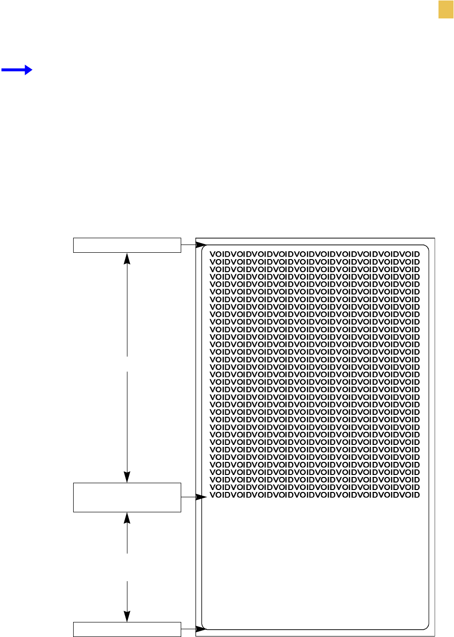
Example • This example sets the printer to move the media to 800 dots from the top of the
media [or label length minus 800 from the bottom (leading edge) of the media] and voids the
rest of the media in case of an error. The printer will try to print two labels, then will pause the
printer if printing and encoding fail.
^XA
^RS,800,,2,P^FS
^XZ
Figure 31 shows the resulting voided label. Note where the void starts. The media has been
moved 800 dot rows from the top of the label (label length minus 800 dot rows from the
bottom (leading edge) of a label) to bring the transponder into the effective area to read/write a
tag. If the printer fails the operation, the rest of the media is voided.
Figure 31 • Sample Voided Label 1
Top of label
Start of RFID
operation
800 dot rows
Bottom of label
Label length minus
800 dot rows
82 R4Mplus User Guide
RFID Guidelines
ZPL II Commands for RFID
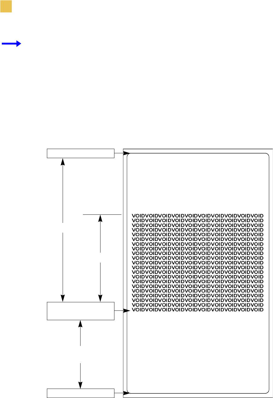
Example • This example sets the printer to move the media to 800 dots from the top of the
media [or label length - 500 from the bottom (leading edge) of the media] and prints “void”
500 dots in vertical length (Y axis) in case of an error.
^XA
^RS,800,500,2,P^FS
^XZ
Figure 32 shows the resulting voided label. Note where the void starts. The media has been
moved 800 dot rows from the top of the label [label length minus 800 dot rows from the
bottom (leading edge) of a label] to bring the transponder into the effective area to read/write a
tag. If the printer fails the operation, an area that is 500 dot rows of the media is voided instead
of the entire rest of the media as in Figure 31.
Figure 32 • Sample Voided Label 2
Top of label
Start of RFID
operation
800 dot rows
Bottom of label
Label length minus
800 dot rows
500 dot rows

RFID Guidelines
Sample of RFID Programming
R4Mplus User Guide 83
Sample of RFID Programming
ZPL II is Zebra’s label design language. ZPL II lets you create a wide variety of labels from
the simple to the very complex, including text, bar codes, and graphics.
This section is not intended as an introduction to ZPL II. If you are a new ZPL II user, order
the ZPL II Programming Guide (part number 46530L) or go to http://support.zebra.com to
download the guide.
For your programming, do the following:
1. Set up the printer and turn the power On (I).
2. Use any word processor or text editor capable of creating ASCII-only files (for example,
use Microsoft® Word and save as a .txt file) and type in the label format exactly as shown
in the sample label format that follows.
3. Save the file in a directory for future use. Use the “.zpl” extension.
4. Copy the file to the printer.
From the DOS command window, use the “COPY” command to send a file to the Zebra
printer. For example, if your file name is format1.zpl then type, COPY FORMAT 1.ZPL
XXXX, where XXXX is the port to which your Zebra printer is connected (such as LPT1).
5. Compare your results with those shown. If your printout does not look like the one shown,
confirm that the file you created is identical to the format shown, then repeat the printing
procedure. If nothing prints, refer to
•Printer Setup on page 7
•Printer Operation on page 21
•Configuration on page 45
•Troubleshooting on page 93
to make sure that your system is set up correctly.

84 R4Mplus User Guide
RFID Guidelines
Sample of RFID Programming
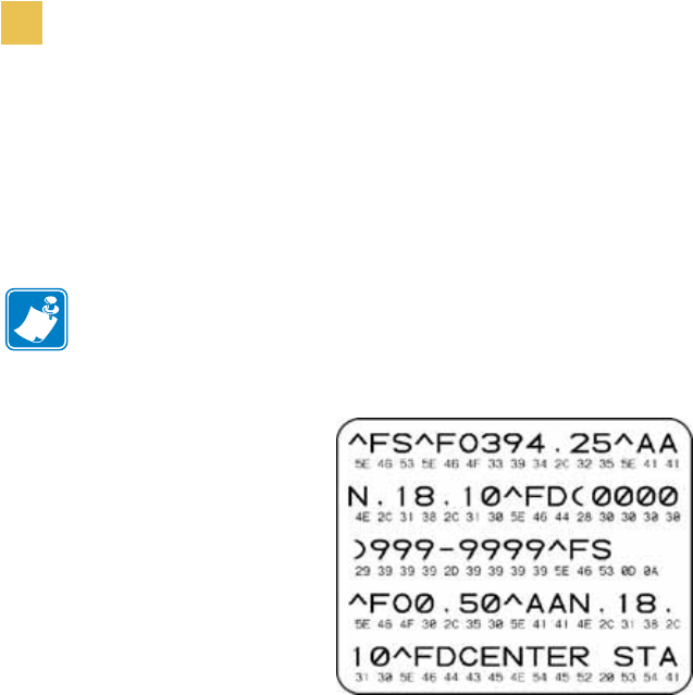
Table 12 • Sample ZPL Code and Results
Line
Number Type This Label Format Resulting Printout
1 ^XA ZEBRA
5A65627261000000
2^RS,0^FS
3^WT^FDZebra^FS
4 ^FO100,100^A0n,60^FN0^FS
5 ^FO100,200^A0n,40^FN1^FS
6^RT0^FS
7 ^RT1,,,1^FS
8^XZ
Line 1 Indicates start of label format.
Line 2 Indicates no movement for media.
Line 3 Writes the data “Zebra” to the tag.
Line 4 Print field number ‘0’ at location 100,100.^FN0 is replaced by what we read on line 6.
Line 5 Print field number ‘1’ at location 100,200. ^FN1 is replaced by what we read on line 7.
Line 6 Read Tag into field number 0 in ASCII format (default).
Line 7 Read Tag into field number 1 in hexadecimal format.
Line 8 End of label format.

R4Mplus User Guide 85
CHAPTER 6
Routine Care and Adjustments
This chapter discusses printer cleaning and minor adjustments.
Contents
Cleaning Procedures . . . . . . . . . . . . . . . . . . . . . . . . . . . . . . . . . . . 86
Clean the Exterior. . . . . . . . . . . . . . . . . . . . . . . . . . . . . . . . . . . . 86
Clean the Interior . . . . . . . . . . . . . . . . . . . . . . . . . . . . . . . . . . . . 87
Clean the Sensors . . . . . . . . . . . . . . . . . . . . . . . . . . . . . . . . . . . 88
Clean the Rewind Option . . . . . . . . . . . . . . . . . . . . . . . . . . . . . . 89
Clean the Peel-Off Assembly . . . . . . . . . . . . . . . . . . . . . . . . . . . 90
Lubrication . . . . . . . . . . . . . . . . . . . . . . . . . . . . . . . . . . . . . . . . . . . 90
Fuse Replacement . . . . . . . . . . . . . . . . . . . . . . . . . . . . . . . . . . . . . 91

86 R4Mplus User Guide
Routine Care and Adjustments
Cleaning Procedures
Cleaning Procedures
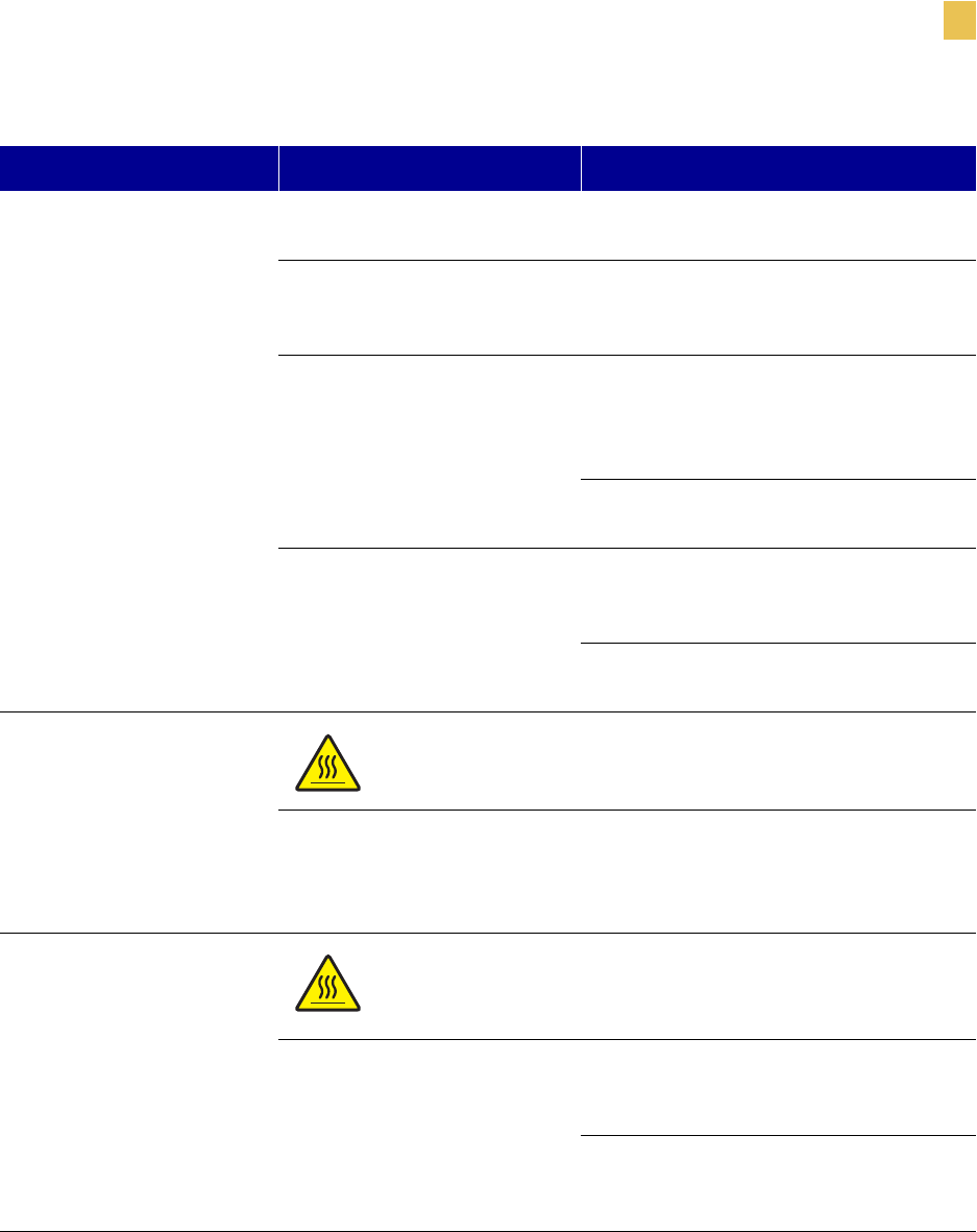
Specific cleaning procedures are provided on the following pages. Table 13 shows a
recommended cleaning schedule.
.
Clean the Exterior
The exterior surfaces of the printer may be cleaned with a lint-free cloth. Do not use harsh or
abrasive cleaning agents or solvents. If necessary, a mild detergent or desktop cleaner may be
used sparingly.
Table 13 • Recommended Cleaning Schedule
Area Method Interval
Printhead Solvent* Direct Thermal Mode: After every roll
of media (or 500 feet of fanfold media).
Thermal Transfer Mode: After every
roll of ribbon or three rolls of media.
These intervals are intended as
guidelines only. You may have to clean
more often, depending upon your
application and media.
Platen roller Solvent*
Media sensors Air blow
Ribbon sensor Air blow
Media path Solvent*
Ribbon path Solvent*
Pinch roller. (Optional peel-off
option required. Refer to Clean the
Peel-Off Assembly on page 90.)
Solvent*
Tear-off/peel-off bar Solvent* Once a month.
Take label sensor Air blow Once every six months.
* Zebra recommends using the Preventive Maintenance Kit, Part Number 47362 or a solution of 90% Isopropyl and 10%
deionized water)
Note • Zebra Technologies Corporation will not be responsible for damage caused by the use
of cleaning fluids on the R4Mplus printer.

Routine Care and Adjustments
Cleaning Procedures
R4Mplus User Guide 87
Clean the Interior
Remove any accumulated dirt and lint from the interior of the printer using a soft bristle brush
or vacuum cleaner.
Clean the Printhead and Platen Roller
You can minimize printhead wear and maintain print quality with regular preventive measures.
Over time, the movement of media/ribbon across the printhead wears through the protective
ceramic coating, exposing and eventually damaging the print elements (dots). In order to avoid
abrasion:
• Clean your printhead frequently and use well-lubricated thermal transfer ribbons with
packagings optimized to reduce friction.
• Minimize printhead pressure and burn temperature settings by optimizing the balance
between the two.
• Ensure that the thermal transfer ribbon is as wide or wider than the label media to prevent
exposing the elements to the more abrasive label material.
For best results, perform the following cleaning procedure after changing every roll of ribbon.
Inconsistent print quality, such as voids in the bar code or graphics, may indicate a dirty
printhead.
To clean the printhead and platen roller, refer to Figure 33 and complete
these steps:
1. Open the printhead assembly.
2. Remove the media and ribbon.
3. Use the Preventive Maintenance Kit (Zebra part number 47362) or a solution of
90% Isopropyl alcohol and 10% deionized water and swab. Wipe along the print elements
from end to end. The print elements are on the brown strip just behind the chrome strip on
the printhead. Allow the solvent to evaporate.
4. Manually rotate the platen roller and clean thoroughly with solvent and a pad.
5. Brush or vacuum any accumulated paper lint and dust away from the media and ribbon
paths.
6. Reload media or ribbon, and close the printhead assembly.
Note • The printer can remain on while you are cleaning the printhead. In this way all label
formats, images, and all temporary parameter settings stored in the printer’s internal memory
are saved. In addition, keep the peel engaged while cleaning the platen roller (media must be
unloaded to do this) to reduce the risk of bending the tear-off/peel-off bar.
Caution • Ensure that the printhead is fully open and engaged in the up position. If the
printhead is not latched in the up position, it could fall on your hand during the procedure.
88 R4Mplus User Guide
Routine Care and Adjustments
Cleaning Procedures
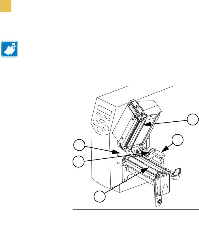
Figure 33 • Cleaning the Printhead and Platen Roller
Clean the Sensors
Brush or vacuum any accumulated paper lint and dust away from the printer sensors. Refer to
Figure 33. The transmissive sensor and ribbon sensor should be cleaned on a regular basis to
ensure proper operation of the printer. For printers with the peel-off, liner take-up, and/or
rewind option(s) installed, clean the take label sensor as well.
Note • If print quality has not improved after performing this procedure, try cleaning the
printhead with Save-A-Printhead cleaning film. This specially coated material removes
contamination buildup without damaging the printhead. Call your authorized Zebra reseller for
more information.
1Printhead Assembly
2Transmissive Sensor
3Platen Roller
4Ribbon Sensor
5Take-Label Sensor
5
1
3
2
4
Routine Care and Adjustments
Cleaning Procedures
R4Mplus User Guide 89
Clean the Rewind Option
The Rewind option is required. Refer to Figure 34 and perform the following procedure if
adhesive buildup begins to affect peel performance.
To clean the Rewind option, complete these steps:
1. Open the printhead assembly.
2. Close the peel assembly to prevent bending the tear-off/peel-off bar during cleaning.
3. Use the Preventive Maintenance Kit (Zebra part number 47362) or a solution of
90% Isopropyl alcohol and 10% deionized water and swab to remove excess adhesive
from the tear-off/peel-off bar. Allow the solvent to evaporate.
4. Open the peel assembly by pivoting the module toward you.
5. Manually rotate the pinch roller and clean thoroughly with solvent and a swab. Allow the
solvent to evaporate.
6. Close the peel assembly.
7. Close the printhead assembly.
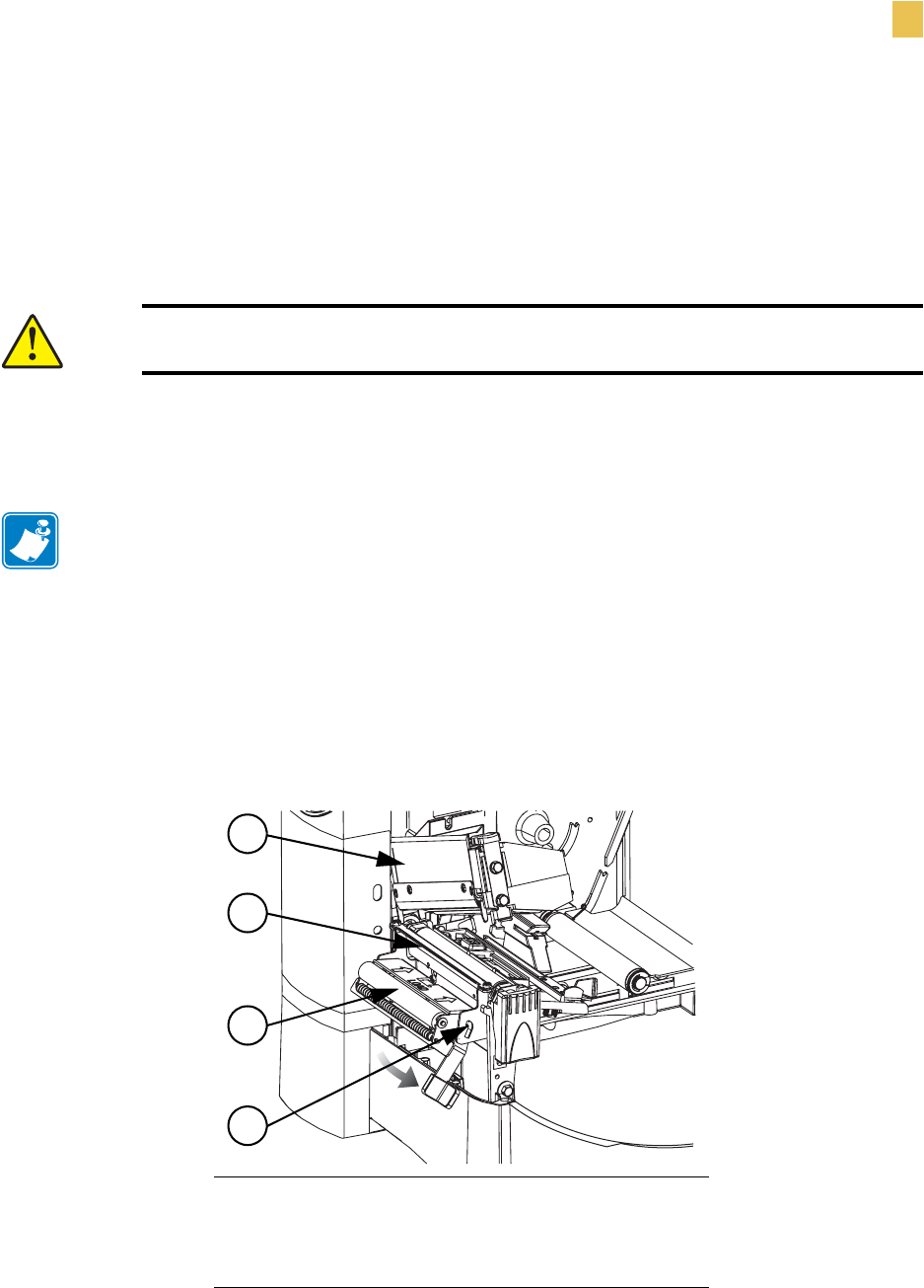
Figure 34 • Cleaning the Rewind Option
Caution • Ensure that the printhead is fully open and engaged in the up position. If the
printhead is not latched in the up position, it could fall on your hand during the procedure.
Note • Apply minimum force when cleaning the tear-off/peel-off bar. Excessive force can
cause the tear-off/peel-off bar to bend, which can have a negative effect on peel
performance.
1Printhead Assembly
2Tear-Off/Peel-Off Bar
3Pinch Roller
4Peel Assembly
3
2
1
4
90 R4Mplus User Guide
Routine Care and Adjustments
Lubrication
Clean the Peel-Off Assembly
The Peel-Off option is required.
If adhesive buildup affects peel-off performance, complete these steps:
1. Open the printhead assembly.
2. Close the peel assembly to prevent bending the tear-off/peel-off bar during cleaning.
3. Use the Preventive Maintenance Kit (Zebra part number 47362) or a solution of
90% Isopropyl alcohol and 10% deionized water and swab to remove excess adhesive
from the tear-off/peel-off bar. Allow the solvent to evaporate.
4. Open the peel assembly by pivoting the module toward you.
5. Manually rotate the pinch roller and clean thoroughly with solvent and a swab.
6. Close the peel assembly.
7. Close the printhead assembly.
Lubrication
No lubrication is needed for this printer.
Caution • Ensure that the printhead is fully open and engaged in the up position. If the
printhead is not latched in the up position, it could fall on your hand during the procedure.
Note • Apply minimum force when cleaning the tear-off/peel-off bar. Excessive force can
cause the tear-off/peel-off bar to bend, which could have a negative effect on peel
performance.
Note • When cleaning the tear-off/peel-off bar or the pinch roller, remove excess solvent
with a pad to ensure the solvent has dried before printing.
Caution • Some commercially available lubricants will damage the finish and the mechanical
parts if used on this printer.

Routine Care and Adjustments
Fuse Replacement
R4Mplus User Guide 91
Fuse Replacement
A user-replaceable AC power fuse is located just below the AC power switch at the rear of the
printer. The replacement fuse is a 5 × 20 mm fast-blow style rated at 5 Amp/250 VAC.
To replace the fuse, complete these steps:
1. To replace the fuse, insert the tip of a flat blade screwdriver into the slot in the end of the
fuse holder end cap.
2. Press in slightly on the end cap and turn the screwdriver slightly counter clockwise. This
disengages the end cap from the fuse holder and permits removal of the fuse.
3. To install a new fuse, remove the old fuse and insert the new fuse into the fuse holder.
4. Push the end cap in slightly, then insert the tip of a flat blade screwdriver into the slot in
the end cap and turn clockwise to engage it.
Electric Shock Caution • Before replacing the fuse, turn off the AC power switch, and
unplug the AC power cord.

92 R4Mplus User Guide
Routine Care and Adjustments
Fuse Replacement

R4Mplus User Guide 93
CHAPTER 7
Troubleshooting
This chapter discusses typical problems and their probable solutions.
Content
LCD Error Conditions and Warnings. . . . . . . . . . . . . . . . . . . . . . . . 94
Print Quality Problems . . . . . . . . . . . . . . . . . . . . . . . . . . . . . . . . . . 97
Calibration Problems . . . . . . . . . . . . . . . . . . . . . . . . . . . . . . . . . . . 98
Communication Problems. . . . . . . . . . . . . . . . . . . . . . . . . . . . . . . . 99
Printer Diagnostics . . . . . . . . . . . . . . . . . . . . . . . . . . . . . . . . . . . . 100
Power-On Self Test. . . . . . . . . . . . . . . . . . . . . . . . . . . . . . . . . . 100
CANCEL Self Test . . . . . . . . . . . . . . . . . . . . . . . . . . . . . . . . . . 101
PAUSE Self Test . . . . . . . . . . . . . . . . . . . . . . . . . . . . . . . . . . . . 102
FEED Self Test . . . . . . . . . . . . . . . . . . . . . . . . . . . . . . . . . . . . . 103
Communication Diagnostics Test . . . . . . . . . . . . . . . . . . . . . . . 104
RFID Test . . . . . . . . . . . . . . . . . . . . . . . . . . . . . . . . . . . . . . . . . 105
Loading Factory Defaults . . . . . . . . . . . . . . . . . . . . . . . . . . . . . . . 106

94 R4Mplus User Guide
Troubleshooting
LCD Error Conditions and Warnings
LCD Error Conditions and Warnings
The LCD displays error condition messages and warnings if the printer detects a problem. The
messages, along with their causes and solutions, are listed in Table 14.
Table 14 • Error Conditions and Warnings
Error Potential Problem Recommended Solution
RIBBON OUT
In thermal transfer mode, the
ribbon is not loaded or loaded
incorrectly.
Load the ribbon correctly. See Load the
Ribbon on page 38.
In thermal transfer mode, the
ribbon sensor is not sensing
correctly loaded ribbon.
Perform the media and ribbon sensor
calibration (see Media and Ribbon
Sensor Calibration (Manual
Calibration) on page 58).
RIBBON IN
In direct thermal mode, when
ribbon is not used: Remove the ribbon and set the printer to
direct thermal mode. See Selecting Print
Method on page 53.
Ensure that the printer driver or software
settings are correctly set.
PAPER OUT
The media is not loaded or
loaded incorrectly. Reload the media. See Load Roll Media
on page 25.
The printer is set for
non-continuous media, but
continuous media is loaded.
Either load the correct media or set the
printer for the correct media type via the
front panel.
Ensure that the printer driver or software
settings are correctly set.
Calibrate the printer (see Media and
Ribbon Sensor Calibration (Manual
Calibration) on page 58).
Troubleshooting
LCD Error Conditions and Warnings
R4Mplus User Guide 95
HEAD OPEN
The printhead is not fully
closed. Close the printhead.
The ribbon is loaded
incorrectly; it is covering the
head open sensor.
Correctly align the ribbon with the guide
mark on the strip plate before closing the
printhead assembly.
Print method is incorrectly set. Via the front panel, locate the PRINT
METHOD menu item and select thermal
transfer mode. See Selecting Print
Method on page 53.
Ensure that the printer driver and/or
software settings are correctly set.
The ribbon is loaded. Remove the ribbon and set the printer to
direct thermal mode. See Selecting Print
Method on page 53.
Ensure that the printer driver and/or
software settings are correctly set.
HEAD OVER TEMP
Caution • The printhead is hot and can cause severe burns.
Allow the printhead to cool.
The printhead is over
temperature. Allow the printer to cool. Printing
automatically resumes when the
printhead elements cool to an acceptable
operating temperature.
HEAD UNDER TEMP
Caution • An improperly connected printhead data or power
cable can cause this error message. The printhead can still be hot
enough to cause severe burns. Allow the printhead to cool.
The printhead is under
temperature. Continue printing while the printhead
reaches the correct operating
temperature.
The environment may be too cold for
proper printing. Relocate the printer to a
warmer area.
Table 14 • Error Conditions and Warnings (Continued)
Error Potential Problem Recommended Solution

96 R4Mplus User Guide
Troubleshooting
LCD Error Conditions and Warnings
OUT OF MEMORY*
*There is not enough memory
to perform the function shown
on the second line of the error
message.
Insufficient DRAM for the label length,
downloaded fonts/graphics, and images.
Ensure that the device, such as FLASH
memory or PCMCIA card, is installed
and not write protected or full.
Ensure that the data is not directed to a
device that is not installed or available.
Table 14 • Error Conditions and Warnings (Continued)
Error Potential Problem Recommended Solution

Troubleshooting
Print Quality Problems
R4Mplus User Guide 97
Print Quality Problems
Table 15 • Print Quality Problems and Solutions
Issue Potential Problem Recommended Solution
General print quality issues You are using an incorrect
media and ribbon combination
for your application.
Consult your authorized
reseller/distributor for information and
advice.
The printer is set at an
excessive print speed to
achieve optimal quality.
For optimal print quality, set the print
speed to a lower setting via ZPL II, the
driver, the software, or the front panel.
The printer is set at an
excessive darkness level to
achieve optimal quality.
For optimal print quality, set the darkness
level to a lower setting via the front
panel, the driver, or the software.
The printhead is dirty. Clean the printhead according to the
instructions in Clean the Printhead and
Platen Roller on page 87.
There is light printing (or no
printing) on the left or right
side of the label or the printed
image is not sharp.
The pressure adjustment dials need to be
adjusted. Follow the printhead pressure
adjustment instructions on Set Printhead
Pressure on page 43.
Gray lines on blank labels
with no consistent pattern The printhead is dirty. Clean the printhead according to the
instructions in Clean the Printhead and
Platen Roller on page 87.
Light, consistent vertical
lines running through all
labels
The printhead or platen roller is
dirty. Clean the printhead, platen roller, or both
according to the instructions in Clean the
Printhead and Platen Roller on page 87.
Intermittent creases on the
left and right edges of the
label
There is too much pressure on
the printhead. Reduce the printhead pressure. See Set
Printhead Pressure on page 43.
Wrinkled ribbon The ribbon is not loaded
correctly. Load the ribbon correctly. See Load the
Ribbon on page 38.
The darkness setting is
incorrect. Set the darkness to the lowest possible
setting for good print quality. See
DARKNESS on page 51.
Incorrect printhead pressure or
balance. Set the pressure to the minimum required
for good print quality. See Set Printhead
Pressure on page 43.
The media is not feeding
correctly. It is walking from
side to side.
Make sure that the media guide and
media supply guide touch the edge of the
media.

98 R4Mplus User Guide
Troubleshooting
Calibration Problems
Calibration Problems
Table 16 • Calibration Problems and Solutions
Problem Recommended Solution
Loss of printing registration on
labels.Excessive vertical drift in top-of-form
registration.
Ensure that the media guides are properly positioned.
Set the printer for the correct media type. See MEDIA
TYPE on page 52.
Reload the media.
Clean the platen roller according to the instructions in
Clean the Printhead and Platen Roller on page 87.
Auto Calibrate failed. Perform a manual calibration (see Media and Ribbon
Sensor Calibration (Manual Calibration) on page 58).
Reload the media.

Troubleshooting
Communication Problems
R4Mplus User Guide 99
Communication Problems
Table 17 • Communication Problems and Solutions
Issue Potential Problem Recommended Solution
The printer does not respond
to print requests. The Data
light does not flash.
Loose or improperly
connected cable. Make sure that the communication cable
is connected properly.
The communication
parameters are incorrect. Check the printer driver or software
communications settings.
Confirm that you are using the correct
communication cable. See Cable
Requirements on page 14.
Via the front panel, check the protocol
setting. It should be set to the default
None. See Setting Protocol on page 61.
Ensure that the correct driver is being
used.
Several labels print, then the
printer skips, misplaces,
misses, or distorts the image
on the label after a label is
sent to the printer.
The host is set to EPP parallel
communications. Change the settings on the computer
host to standard parallel
communications.
The serial communication
settings are incorrect. Standard RS-232 cables are appropriate
for lengths under 50 ft. (15.2 m);
RS-422 and RS-485 cables allow serial
transmission up to 4000 ft.(1.2 km).
Check cable length and shielding, and
confirm the appropriate RS-232,
RS-422, or RS-485 setting is being used.
Check the printer driver or software
communications settings.
A label format was sent to the
printer but not recognized.
The DATA light flashes but
no printing occurs.
The prefix and delimiter
characters set in the printer do
not match the ones in the label
format.
Verify the prefix and delimiter
characters. See Selecting Prefix and
Delimiter Characters (next three
parameters) on page 63.
Incorrect data is being sent to
the printer. Check the communication settings on
the computer. Ensure that they match
the printer settings.

100 R4Mplus User Guide
Troubleshooting
Printer Diagnostics
Printer Diagnostics
These self tests produce sample printouts and provide specific information that help determine
the operating conditions for the printer.
Each self test is enabled by pressing a specific front panel key or combination of keys while
turning the printer On (l). Press the key(s) until the DATA light turns off (approximately five
seconds). When the Power-On Self Test is complete, the selected self test starts automatically.
Power-On Self Test
A Power-On Self Test (POST) is performed automatically each time the printer is turned on.
During this test sequence, the front panel lights and liquid crystal display (LCD) monitor the
progress of the POST. If the printer fails any of these tests, the word FAILED is display. If this
occurs, notify an authorized Zebra reseller.
Note • Keep the following in mind while performing self tests:
• When performing self tests, avoid sending a label format to the printer. In the
case of a remote host, disconnect all data interface cables from the printer.
• When cancelling a self test prior to its actual completion, always turn the printer
Off (O) and then back On (I) to reset the printer.
• When performing these self tests while in the Peel-Off Mode, you must remove
the labels as they become available.
• If your media is not wide enough or long enough, unexpected or undesired
results may occur. Ensure that your print width is set correctly for the media
you are using before you run any self tests, otherwise the test may print on the
platen roller. See PRINT WIDTH on page 53 for information on setting the print
width.
Troubleshooting
Printer Diagnostics
R4Mplus User Guide 101
CANCEL Self Test
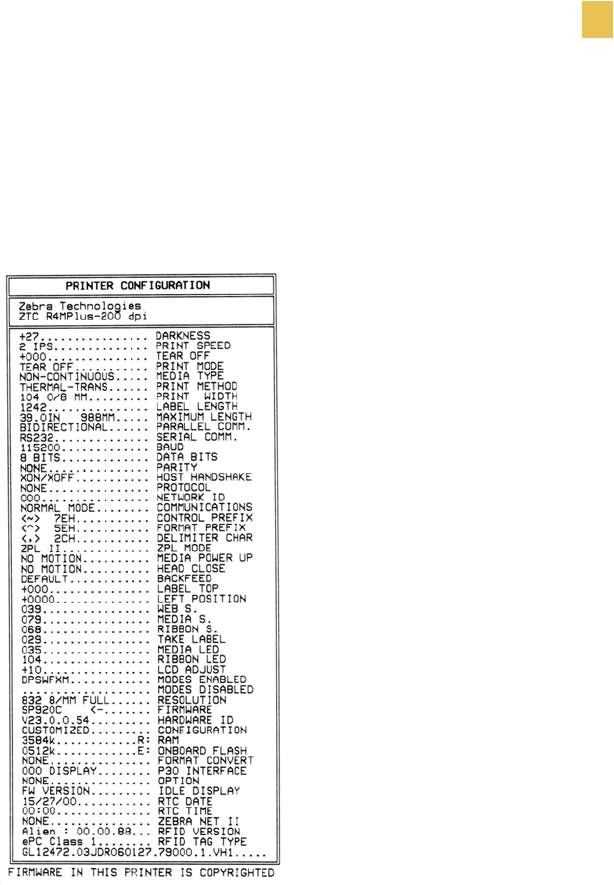
This self test prints a listing of the configuration parameters currently stored in the printer’s
memory. See Figure 35. Depending on the options ordered, your label may look different.
Figure 35 • Sample Configuration Label
The configuration shown on the label may be changed either temporarily (for specific label
formats or ribbon and label stock) or permanently (by saving the new parameters in memory).
See Basic Configuration on page 48 for further information about the configuration procedure.
To perform the CANCEL Self Test, complete these steps:
1. Turn the printer Off (O).
2. Press and hold CANCEL while turning On (l) the printer.
3. Release CANCEL after the DATA light turns off (approximately five seconds).

102 R4Mplus User Guide
Troubleshooting
Printer Diagnostics
PAUSE Self Test
This self test can be used to provide the test labels required when making adjustments to the
printer’s mechanical assemblies or parameter settings. See the sample printout in Figure 36.
Figure 36 • PAUSE Test Label
To perform the PAUSE Self Test, complete these steps:
1. Turn the printer Off (O).
2. Press and hold PAUSE while turning On (l) the printer.
3. Release PAUSE after the DATA light turns off (approximately five seconds).
The printer prints 15 labels at 2 in. (51 mm) per second, then automatically pauses. If
PAUSE is pressed, an additional 15 labels print.
4. Press CANCEL while the printer is paused to alter the self test, then press PAUSE.
The printer prints 15 labels at 6 in. (152 mm) per second, then automatically pauses.
5. Press CANCEL again while the printer is paused to alter the self test again, then press
PAUSE.
The printer prints 50 labels at 2 in. (51 mm) per second, then automatically pauses.
6. Press CANCEL again while the printer is paused to alter the self test a third time, then
press PAUSE.
The printer prints 50 labels at 6 in. (152 mm) per second, then automatically pauses.
7. Press CANCEL again while the printer is paused to alter the self test a fourth time, then
press PAUSE.
The printer prints 15 labels at the printer’s maximum speed.
8. To exit this self test at any time, press and hold CANCEL.

Troubleshooting
Printer Diagnostics
R4Mplus User Guide 103
FEED Self Test
See Figure 37. The FEED Self Test prints labels at various darkness settings above and below
that of the darkness value currently stored in the printer (shown on the first line of the
configuration label). The relative darkness value printed on the best FEED Self Test label is
added to or subtracted from the darkness value. The resulting numeric value (0 to 30) is the
best darkness value for that specific media and ribbon combination.
For example, if the darkness value on a printer is 10 and the best relative darkness value is
zero, leave the darkness setting as is. If the best relative darkness value is –1, change the
darkness setting on your printer to 9 (10 – 1). If the best relative darkness value is 2, change
the darkness setting to 12 (10 + 2).
Figure 37 • FEED Self Test Label, Relative Darkness Value Zero
To perform the FEED Self Test, complete these steps:
1. Turn the printer Off (O).
2. Press and hold FEED while turning On (l) the printer.
3. Release FEED after the DATA light turns off (approximately five seconds).
4. Find the label that has the best darkness setting for your application.
5. If the relative darkness value on this label is a number other than zero (values range from
–3 to 3), adjust the darkness setting on your printer by adding or subtracting that relative
darkness value from the current darkness setting. See Adjusting Print Darkness
on page 51 for more information.
104 R4Mplus User Guide
Troubleshooting
Printer Diagnostics
Communication Diagnostics Test
This test is controlled from the front panel display (see Setting Communication Diagnostics
Mode on page 62). A typical printout from this test is shown in Figure 38. Turn the printer Off
(O) to exit this self test.
Figure 38 • Communication Diagnostics Test Printout
Note • This label is inverted when printed (prints upside down).
Troubleshooting
Printer Diagnostics
R4Mplus User Guide 105
RFID Test
The RFID test is controlled from the front panel display (see RFID Test on page 69). If the
printer fails the test, the front panel displays an error message.
You have the option of running the RFID test in two ways: quick or slow. In both versions of
this test, the printer attempts to read and write to a transponder. In the slow test, the printer also
checks the reader version number and displays the tests on the LCD as it runs through them.
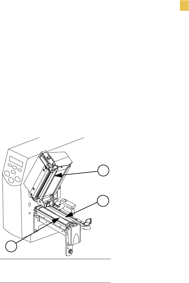
To perform the RFID Test, complete these steps:
1. See Figure 39. Place an RFID label in the printer so the embedded transponder is over the
open area behind the platen roller (no movement occurs with the test).
Figure 39 • Label Placement for RFID Test
2. From the front panel, press SETUP/EXIT.
3. Press PLUS (+) or MINUS (–) until you reach
RFID TEST
.
4. Press SELECT to select the parameter.
5. Press MINUS (–) to select
QUICK
.
or
Press PLUS (+) to select
SLOW
.
• For the quick test, the results are
PASSED
and
FAILED
. Press PLUS (+) to continue.
• For the slow test, a pass result returns you to the
RFID
TEST
menu item. A failed result
returns the message
WRITE
ERROR
. Press PLUS (+) to continue.
6. Press SELECT to deselect the parameter.
1Printhead Assembly
2Open Area
3Platen Roller
1
3
2

106 R4Mplus User Guide
Troubleshooting
Loading Factory Defaults
Loading Factory Defaults
Use care when loading defaults. You will need to reload all settings that you changed
manually.
To load the factory defaults, complete these steps:
1. Press SETUP/EXIT two times.
2. Use PLUS (+) or MINUS (–) to scroll through the SAVE CHANGES choices.
3. When LOAD DEFAULTS displays, press SETUP/EXIT.

R4Mplus User Guide 107
APPENDIX A
Data Connections
This appendix provides details about the serial port and parallel port data connections.
Content
Serial Data Port . . . . . . . . . . . . . . . . . . . . . . . . . . . . . . . . . . . . . . 108
Hardware Control Signal Descriptions . . . . . . . . . . . . . . . . . . . 108
RS-232 Serial Data Port . . . . . . . . . . . . . . . . . . . . . . . . . . . . . . 108
Parallel Data Port . . . . . . . . . . . . . . . . . . . . . . . . . . . . . . . . . . . . . 112
Parallel Cabling Requirements . . . . . . . . . . . . . . . . . . . . . . . . . 112
Parallel Port Interconnections. . . . . . . . . . . . . . . . . . . . . . . . . . 112

108 R4Mplus User Guide
Data Connections
Serial Data Port
Serial Data Port
Hardware Control Signal Descriptions
For all RS-232 input and output signals, the R4Mplus printer follows both the Electronics
Industries Association (EIA) RS-232 and the Consultative Committee for International
Telegraph and Telephone (CCITT) V.24 standard signal level specifications.
When DTR/DSR handshaking is selected, the Data Terminal Ready (DTR) control signal
output from the printer controls when the host computer may send data. DTR ACTIVE
(positive voltage) permits the host to send data. When the printer places DTR in the
INACTIVE (negative voltage) state, the host must not send data.
Request to send (RTS) is a control signal from the printer that is connected to the clear to send
(CTS) input at the host computer. RTS is always active (positive voltage) when the printer
is on.
RS-232 Serial Data Port
The connection for this standard interface is made through the female DB-9 connector on the
rear panel. A DB-9 to DB-25 interface module is required for all RS-232 connections through
a DB-25 cable (see page 110 for details).
For all RS-232 input and output signals, the printer follows both the Electronics Industries
Association’s (EIA) RS-232 specifications and the Consultative Committee for International
Telegraph and Telephone (CCITT) V.24 standard signal level specifications.
Table 18 shows the pin configuration and function of the rear panel serial data connector on
the printer.
Note • When XON/XOFF handshaking is selected, data flow is controlled by the ASCII
Control Codes DC1 (XON) and DC3 (XOFF). The DTR Control lead has no effect.
Table 18 • Serial Data Connector Pin Configuration
Pin Number Name Description
1 — Not connected
2 RXD Receive data—data input to printer
3 TXD Transmit data—data output from printer
4 DTR Data terminal ready—output from printer
5 SG Signal ground
6 DSR Data set ready—input to printer
7 RTS Request to send—output from printer
Data Connections
Serial Data Port
R4Mplus User Guide 109
RS-232 Interface Connections
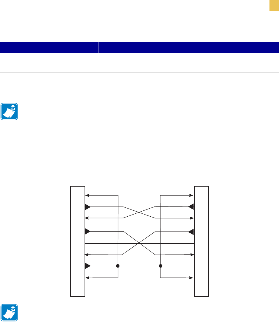
The printer is configured as Data Terminal Equipment (DTE). Figure 40 shows the internal
connections of the printer’s RS-232 connector.
Figure 40 • RS-232 Internal Connections
8 CTS Clear to send—input to printer
*9 +5 V DC +5 VDC
* This pin is also available as a +5 VDC power source at 750 mA. To enable this capability, a jumper on the computer’s
main logic board needs to be installed on JP1, pins 2 and 3.
Note • An interface module is required for RS-422/RS-485 interface support
(refer to page 111).
Note • You must use a a null modem (crossover) cable to connect the printer to a computer or
any other DTE devices.
Table 18 • Serial Data Connector Pin Configuration (Continued)
Pin Number Name Description
1
(TD) (TD)
(RD) (RD)
(RTS) (RTS)
(DSR) (DSR)
(SG) (SG)
(DTR) (DTR)
DTE DTE
1
22
33
44
55
66
77
88
99
110 R4Mplus User Guide
Data Connections
Serial Data Port
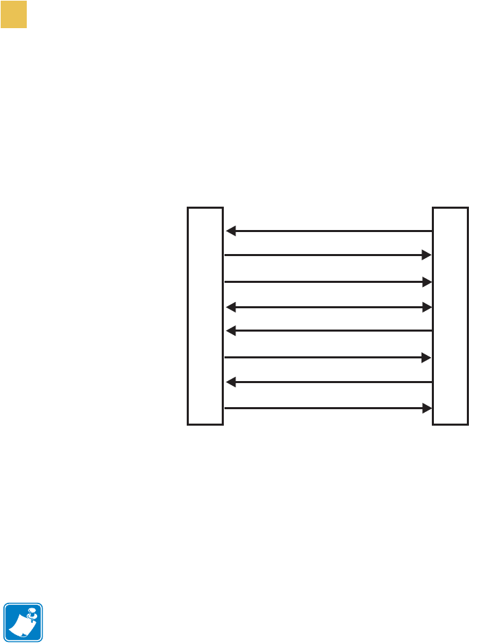
When the printer is connected via its RS-232 interface to Data Communication Equipment
(DCE) such as a modem, use a standard RS-232 (straight-through) interface cable. Figure 41
illustrates the connections required for this cable.
Figure 41 • RS-232 to DCE Internal Connections
RS-232 Interconnections Using a DB-25 Cable
To connect the printer’s RS-232 DB-9 interface to a DB-25 connector, an interface adapter is
required (Zebra part number 33138). A generic DB-25 adapter may also be used, however, the
+5 VDC signal source would not be passed through. Figure 42 shows the connections required
for the DB-9 to DB-25 interface.
Note • You must use a a null modem (crossover) cable to connect the printer to a computer or
any other DTE devices.
DTE
(Printer)
DCE
(Modem, etc.)
RXD (receive data)
TXD (transmit data)
DTR (data terminal ready)
SG (signal ground)
DSR (data set ready)
RTS (request to send)
CTS (clear to send)
+5 VDC signal source
NOTE • Pin 1 is unused and unterminated at the printer.
2
3
4
5
6
7
8
9
2
3
4
5
6
7
8
9
Data Connections
Serial Data Port
R4Mplus User Guide 111
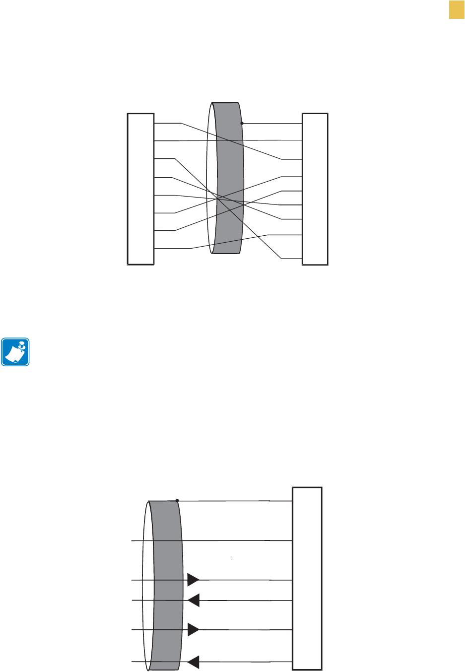
Figure 42 • DB-9 to DB-25 Internal Connections
RS-422/RS-485 Interconnections
To connect the printer’s RS-232 DB-9 interface to a host computer through an RS-422 or an
RS-485 interface, an interface adapter is required (Zebra part number 33130). Figure 43 shows
the required cable wiring for interconnecting to the interface adapter’s DB-25 female
connector.
Figure 43 • RS-422 and RS-485 Adapter Internal Connections
Note • A jumper on the computer’s main logic board needs to be installed on JP1, Pins 2
and 3, for the RS-422/RS-485 interface adapter to function properly.
Male DB-9 Adapter
Connector
(plugs into printer)
Female DB-25 Adapter
Connector
(plugs into cable)
Note • Pin 1 of DB-9 connector is unused and unterminated.
FG
TXD
RXD
RTS
DSR
SG
DTR
RXD
TXD
DTR
SG
DSR
RTS
CTS
+5 VDC
SIGNAL
2
3
4
5
6
7
8
9
1
2
3
4
6
7
9
20
+5 VDC
SIGNAL
5
CTS
DB-25P
Connector
to Printer
Data Input A (–)
Data Output A (–)
Data Output B (+)
Data Input B (+)
Shield
Signal Ground
1
11
13
14
16
19

112 R4Mplus User Guide
Data Connections
Parallel Data Port
Parallel Data Port
The 8-bit parallel data interface supports IEEE 1284 bidirectional parallel communications in
nibble mode. The parallel interface provides a means of communication that is typically faster
than the previously mentioned serial interface methods. In this method, the bits of data that
make up a character are sent all at one time over several wires in the cable, one bit per wire.
Parallel Cabling Requirements
An IEEE-1284 compatible bi-directional parallel data cable is required when this
communication method is used. The required cable must have a standard 36-pin parallel
connector on one end that is plugged into the mating connector located at the rear of the
printer. The other end of the cable connects to the printer connector at the host computer. Port
selection for status information is determined each time the printer is turned on.
Parallel Port Interconnections
Table 19 shows the pin configuration and function of a standard computer-to-printer parallel
cable.
Table 19 • Parallel Cable Pin Configuration
36-Pin Connectors Description
1 nStrobe/HostClk
2 to 9 Data Bits 1 to 8
10 nACK/PtrClk
11 Busy/PtrBusy
12 PError/ACKDataReq
13 Select/Xflag
14 nAutoFd/HostBusy
15 Not used
16 and 17 Ground
18 +5V @ 750 mA
The maximum current draw may be limited by option configuration.
19 to 30 Ground
31 nInit
32 nFault/NDataAvail
33 and 34 Not used
35 +5V through a 1.8KΩ Resistor
36 NSelectin/1284 active

R4Mplus User Guide 113
APPENDIX B
Specifications
This appendix contains specifications for the R4Mplus printer.
Contents
General Specifications . . . . . . . . . . . . . . . . . . . . . . . . . . . . . . . . . 114
Printing Specifications. . . . . . . . . . . . . . . . . . . . . . . . . . . . . . . . . . 115
Media Specifications . . . . . . . . . . . . . . . . . . . . . . . . . . . . . . . . . . . 116
Ribbon Specifications . . . . . . . . . . . . . . . . . . . . . . . . . . . . . . . . . . 117
Printer Options . . . . . . . . . . . . . . . . . . . . . . . . . . . . . . . . . . . . . . . 118
Zebra Programming Language (ZPL II) Features. . . . . . . . . . . . . 119
Supported Bar Codes . . . . . . . . . . . . . . . . . . . . . . . . . . . . . . . . . . 119

114 R4Mplus User Guide
Specifications
General Specifications
General Specifications
Table 20 • R4Mplus General Specifications
General Specifications
Height 13.3 in. 338 mm
Width 10.9 in. 277 mm
Depth 18.7 in. 475 mm
Weight (without options) 32.4 lbs. 14.7 kg
Electrical 90-265 VAC, 48-62 Hz, 5 Amps (fused)
Agency Approvals •UL 60950-1
•CAN/CSA - C22.2 NO. 60950-1-03
•FCC Part 15.107 and 15.109 Class B
•FCC Part 15.247
•Canadian ICES-003, Class B
•IC RSS-210
Temperature Operating 40° to 104°F 5° to 40°C
Storage –40° to 140°F –40° to 60°C
Relative Humidity Operating 20% to 85%, non-condensing
Storage 5% to 85%, non-condensing
Communication Interface RS-232/CCITT V.24 serial data interface; 110
to115000 baud, parity, bits/character, 7 or 8 data
bit, and XON-XOFF, RTS/CTS or DTR/DSR
handshake protocol required. 750mA at 5 V from
pin 9.
8-bit parallel data interface; supports IEEE 1284
bidirectional parallel, ECP and nibble mode
compliant. Error detection CRC protocol.

Specifications
Printing Specifications
R4Mplus User Guide 115
Printing Specifications
Table 21 • R4Mplus Printing Specifications
Printing Specifications
Print resolution 203 dots/inch 8 dots/mm
300 dots/inch 12 dots/mm
Dot size
(width x length)
203 dpi 0.00492 in. x 0.00492 in. 0.125 mm x 0.125 mm
300 dpi 0.0033 in. x 0.0039 in. 0.084 mm x 0.099 mm
Maximum print
width 203 dpi 4.09 in. 104 mm
300 dpi 4.1 in. 106 mm
Minimum print length 1 dot row
Maximum print
length 203 dots/inch 105 in. 2667 mm
300 dots/inch 45 in. 1143 mm
Bar code modulus
(X) dimension
203 dots/inch 5 mil to 50 mil
300 dots/inch 3.3 mil to 33 mil
Programmable
constant print speeds 203 dots/inch Per second:
7in.
8 in.
9 in.
10 in.
Per second:
178 mm
203 mm
229 mm
254 mm
300 dots/inch Per second:
2 in.
3 in.
4 in.
5in.
6in.
Per second:
51 mm
76 mm
102 mm
127 mm
152 mm
Thin film printhead with energy control

116 R4Mplus User Guide
Specifications
Media Specifications
Media Specifications
Table 22 • R4Mplus Media Specifications
Media Specifications
Label length Minimum Tear-off 0.5 in.* 13 mm*
Peel-off 1 in.* 25.4 mm*
Rewind 0.5 in.* 13 mm*
RFID “Smart” labels **
Maximum Tear/Peel/Rewind 39 in.* 991 mm*
RFID “Smart” labels **
Label width Minimum Tear/Peel/Rewind 1 in.* 25.4 mm*
RFID “Smart” labels **
Maximum Tear 4.5 in. 114 mm
Peel/Rewind 4.25 in. 108 mm
Total thickness
(includes liner, if any) Minimum 0.0023 in. 0.058 mm
Maximum 0.010 in. 0.25 mm
Core size 3 in. 76 mm
Maximum roll diameter 8 in. 203 mm
Inter-label gap Minimum 0.079 in.* 2 mm*
Preferred 0.118 in.* 3 mm*
Maximum 0.157 in.* 4 mm*
RFID “Smart” labels **
Ticket/tag notch size (width x length) 0.236 in. × 0.12 in. 6 mm × 3 mm
Hole diameter 0.125 in. 3 mm
Notch or hole position
(Centered from inner
media edge)
Minimum 0.15 in. 3.8 mm
Maximum 2.25 in. 57 mm
Density, in Optical Density Units (UDO) > 1.0 ODU
Maximum media density < 0.5 ODU
Transmissive Sensor Fixed 7/16 in. (11 mm) from inside edge
* Does not apply to RFID “smart” labels.
** This parameter varies for each transponder type. For the list of approved transponders and related placement
specifications, go to http://www.rfid.zebra.com/r4m.htm.

Specifications
Ribbon Specifications
R4Mplus User Guide 117
Ribbon Specifications
Table 23 • R4Mplus Ribbon Specifications
Ribbon Specifications
Ribbon must be wound with the coated side out
Ribbon width
(Zebra recommends using ribbon at
least as wide as the media to protect
the printhead from wear.)
Minimum* >2 in.** 51 mm**
Maximum 4.3 in. 109 mm
Standard lengths 2:1 media to ribbon
roll ratio 984 ft. 300 m
3:1 media to ribbon
roll ratio 1476 ft. 450 m
Ribbon core inside diameter 1 in. 25.4 mm
* For RFID “smart” labels, the minimum ribbon width is determined by the minimum label width for
the transponder being used. For the list of approved transponders and related size and placement
specifications, go to http://www.rfid.zebra.com/r4m.htm.
** Depending on your application, you may be able to use ribbon narrower than 2 in. (51 mm), as long as
the ribbon is wider than the media being used. To use a narrower ribbon, test the ribbon’s performance
with your media to assure that you get the desired results.

118 R4Mplus User Guide
Specifications
Printer Options
Printer Options
•Peel-off
•Liner take-up
•PCMCIA card socket (supports Zebra Rapid Flash and ATA formats)
•Linear Memory Card: (Zebra Rapid Flash) 8MB and 32MB
•Compact Flash: 32MB, 64MB, 128MB, and 256MB
•300 dpi printhead
•Rewind
•Adjustable transmissive sensor
•External PrintServer
•Internal PrintServer

Specifications
Zebra Programming Language (ZPL II) Features
R4Mplus User Guide 119
Zebra Programming Language (ZPL II) Features
•Downloadable graphics (with data compression)
•Bit image data transfer and printing, mixed text/graphics
•Format inversion
•Mirror image printing
•Four-position field rotation
(0°, 90°, 180°, 270°)
•Slew command
•Programmable quantity with print pause
•Communicates in printable ASCII characters
•Controlled via mainframe, mini, PC, portable data terminal
•In-Spec OCR-A and OCR-B
•UPC/EAN
(nominal 100% magnification 6 dots/mm printheads only)
•Serialized fields
Supported Bar Codes
Table 24 • Supported Bar Codes
R4Mplus Bar Code Features
Code 11 LOGMARS
Code 39 (supports ratios of 2:1 to 3:1) Plessey
Code 49 (2-dimensional bar code) EAN-8, EAN-13, EAN EXTENSIONS
Code 93 UPC-A, UPC-E, UPC EXTENSIONS
Code 128 (supports serialization in all
subsets and UCC case codes) MSI
Codabar (supports ratios of 2:1 to 3:1) PDF-417 (2-dimensional bar code)
Codablock Micro-PDF-417
Interleaved 2 of 5 (supports ratios of 2:1 to
3:1; modulus 10 check digit) POSTNET
Industrial 2 of 5 MaxiCode
Standard 2 of 5 Datamatrix
QR Code Check digit calculation where applicable

120 R4Mplus User Guide
Specifications
Supported Bar Codes

R4Mplus User Guide 121
Index
A
about this document, xxi
AC power cord specifications, 11
addresses, xx
adjustments
darkness, 51
label left position, 66
label top position, 65
LCD display, 66
media alignment for rewind, 35
printhead pressure, 43
print speed, 51
tear-off position, 52
auto calibration, 40
B
backfeed sequence, 65
bar codes
list available, 54
supported by this printer, 119
basic configuration, 48
baud rate
setting through front panel, 59
before you begin setup, 8
C
cabling requirements, 14
calibration
auto versus manual, 40
head close action, 64
manual calibration procedure, 58
media power up action, 64
troubleshooting problems, 98
CANCEL self test, 101
checklist for printer setup, 8
cleaning
peel-off assembly, 90
printhead and platen roller, 87
rewind option, 89
communication diagnostics
setting, 62
test and sample label, 104
communication interfaces, 13
communication problems, 99
configuration
basic configuration, 48
changing password-protected parameters, 47
enter configuration mode, 46
exit configuration mode, 46
LCD displays, 51
configuration label
printing and example, 41
connect printer to data source, 13
contacts, xx
continuous media, 16
control prefix character, 63
customer support, xx

122 R4Mplus User Guide
Index
D
darkness adjustment
FEED key self test, 103
procedure, 51
data bits, 60
data cable requirements, 14
data communications
parallel ports, 112
serial port, 108
data ports
parallel, 112
serial, 108
data source connections, 10
date change for RTC, 67
default gateway, 69
delimiter character, 63
diagnostics
RFID test, 69
diagnostic tests, 100
direct thermal mode
media scratch test, 18
selecting through front panel, 53
display language, 70
document conventions, xxii
dpi conversion, 67
E
electronics cover, 2
enter configuration mode, 46
exit configuration mode, 46
external view of printer, 2
F
factory defaults, 106
fanfold media loading, 36
FCC radiation exposure limits, viii
FEED key self test, 103
flash memory initialization, 56
font list, 54
format convert setting, 67
format prefix character, 63
formats list, 54
front panel
adjusting LCD display, 66
keys described, 23
LCD display settings, 4
lights described, 24
location, 2
location of keys and lights, 3
overview and illustration, 22
G
general specifications, 114
H
handshake protocol, 60
hardware control signal descriptions, 108
head close action, 64
Head Open
message, 95
Head Over Temp
message, 95
Head Under Temp
message, 95
host handshake, 60
humidity requirements, 10
I
idle display for RTC, 67
images list, 54
initialize flash memory, 56
initialize memory card, 55
inspect printer, 9
install memory card, 44
interconnections
parallel port, 112
RS-232, 109
RS-422/RS-485, 111
interfaces
data connections, 107
system connections, 13
international safety organization marks, 12
IP address, 68
IP protocols, 68
IP resolution, 68

Index
R4Mplus User Guide 123
L
label left position adjustment, 66
label top position adjustment, 65
language displayed, 70
LCD display adjustment, 66
LCD error conditions and warnings, 94
left edge of label adjustment, 66
liner removal
liner take-up mode, 30
rewind/peel-off mode, 32
liner take-up mode
liner removal, 30
loading media, 29
list
all information, 55
bar codes, 54
fonts, 54
formats, 54
images, 54
setup, 54
load factory defaults, 106
loading ribbon, 38
lubrication, 90
M
manual calibration, 40
maximum label length setting, 53
media
non-continuous web media, 16
RFID “smart” labels, 17
specifications, 116
types of media, 15
media door, 2
media loading
fanfold media, 36
liner take-up mode, 29
peel-off mode, 27
rewind/peel-off mode, 31
tear-off mode, 25
media power up action, 64
media removal
rewind mode, 34
media scratch test, 18
media sensor calibration, 58
media sensor profile, 57
media types
continuous media, 16
setting through front panel, 52
memory card
initialize through front panel, 55
installation, 44
N
network ID setting, 61
O
operating conditions, 10
Out of Memory
message, 96
P
Paper Out
message, 94
parallel cabling requirements, 112
parallel communications
parallel data port, 112
setting through front panel, 59
parity, 60
password level, 69
password-protected parameters, 47
PAUSE key self test, 102
PCMCIA card installation, 44
peel-off mode
backfeed sequence setting, 65
cleaning peel-off assembly, 90
liner removal, 32
loading media, 27
pinouts
parallel port, 112
serial port, 108
power cord specifications, 11
Power-On Self Test (POST), 100
power-up media action, 64
print configuration label, 41
print darkness adjustment, 51
printer calibration, 40
printer diagnostics, 100
printer parameters
basic configuration, 48
LCD displays, 51
password protection, 47
printer setup checklist, 8

124 R4Mplus User Guide
Index
printer storage requirements, 9
printhead
cleaning, 87
head close action, 64
pressure adjustment, 43
printing specifications, 115
print method selection, 53
print mode
selection, 52
print modes
described, 5
tear-off mode, 25
print quality problems, 97
PrintServer II (PSII)
default gateway, 69
IP address, 68
IP protocols, 68
IP resolution, 68
password level, 69
subnet mask, 68
print speed adjustment, 51
print width setting, 53
proprietary statement, vii
protocol setting, 61
R
radiation exposure limits, viii
real-time clock (RTC)
date change, 67
idle display, 67
time change, 67
registration problems, 98
relative humidity requirements, 10
removing
printed media from rewind spindle, 34
ribbon, 39
replacing fuse, 91
reporting shipping damage, 9
resolution effects on formats, 67
rewind mode
adjust media alignment, 35
cleaning rewind option, 89
liner removal, 32
loading media, 31
removing printed media, 34
RFID
error status, 69
guidelines, 71
RFID test, 69
RFID test procedure, 105
sample ZPL commands, 83
“smart” labels, 17
transponder placement, 72
ZPL commands, 73
ribbon
determining coated side, 18
loading, 38
removing, 39
Ribbon In
message, 94
Ribbon Out
message, 94
specifications, 117
troubleshooting wrinkles, 97
ribbon scratch test, 18
ribbon sensor calibration, 58
roll media loading, 25
RS-232 serial data port, 108
ruse replacement, 91
S
scratch test
meida type, 18
ribbon coated side, 18
select a printer site, 10
self tests
CANCEL key, 101
communication diagnostics, 104
FEED key, 103
PAUSE key, 102
RFID, 105
sensor profile, 57
serial communications
setting through front panel, 59
serial data port, 108
setup checklist, 8
shipping damage, 9
site requirements, 10
“smart” labels, 17
spacing requirements, 10

Index
R4Mplus User Guide 125
specifications
AC power cord, 11
general, 114
media, 116
printing, 115
ribbon, 117
supported bar codes, 119
Zebra Programming Language (ZPL II), 119
storage requirements, 9
subnet mask, 68
support, xx
surface for the printer, 10
system interfaces, 13
T
tear-off mode
loading media, 25
tear-off position adjustment, 52
temperature requirements, 10
thermal transfer mode
media scratch test, 18
selecting through front panel, 53
time change for RTC, 67
top of label adjustment, 65
transponder placement, 72
types of media
continuous media, 16
non-continuous web media, 16
RFID “smart” labels, 17
U
unpack printer, 9
W
web media, 16
Z
Zebra Programming Language (ZPL II)
^HV, Host Verification, 78
^RS, RFID Setup, 79
^RT, Read Tag, 76
^WT, Write Tag, 74
features, 119
prefix and delimiter characters, 63
sample RFID Programming, 83
selecting ZPL mode, 64

126 R4Mplus User Guide
Index

Zebra Technologies Corporation
333 Corporate Woods Parkway
Vernon Hills, Illinois 60061.3109 U.S.A.
Telephone: +1 847.634.6700
Facsimile: +1 847.913.8766
Zebra Technologies Europe Limited
Zebra House
The Valley Centre, Gordon Road
High Wycombe
Buckinghamshire HP13 6EQ, UK
Telephone: +44 (0) 1494 472872
Facsimile: +44 (0) 1494 450103
Customer Order # 21067L
Manufacturer Part # 21067L Rev. A
© 2005 ZIH Corp.