Zebra Technologies WPT-3200 Proximity Communications Device User Manual Installation020921

Zebra Technologies Corporation Proximity Communications Device Installation020921

Contents

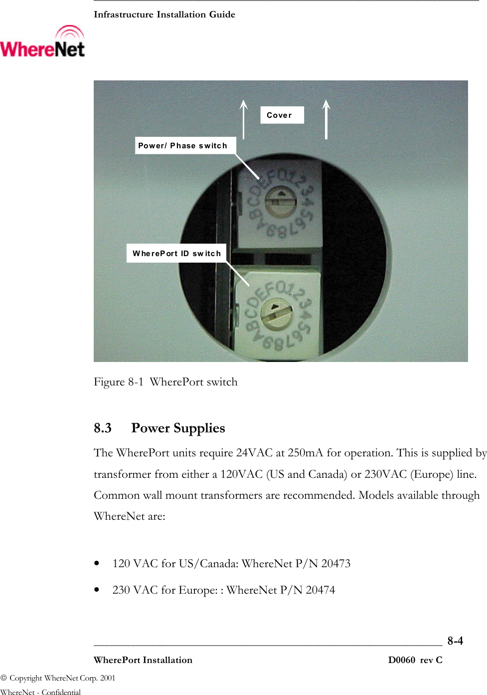
WherePort Installation Manual

 __________________________________________________________________________  Infrastructure Installation Guide       ___________________________________________________________________  8-1  WherePort Installation D0060  rev C  Copyright WhereNet Corp. 2001   WhereNet - Confidential WHEREPORT INSTALLATION
 __________________________________________________________________________  Infrastructure Installation Guide       ___________________________________________________________________  8-2  WherePort Installation D0060  rev C  Copyright WhereNet Corp. 2001   WhereNet - Confidential Table of Contents Page 8  WHEREPORT INSTALLATION  2 8.1  EQUIPMENT REQUIRED   3 8.2  SWITCH SETTINGS   3 8.3  POWER SUPPLIES   4 8.4  WIRING  5 8.5  MOUNTING  7 8.6  INDICATOR LIGHT  8   Table of Figures Page FIGURE 8-1 WHEREPORT SWITCH  4 FIGURE 8-2 POWER AND SIGNAL WIRING  7
 __________________________________________________________________________  Infrastructure Installation Guide       ___________________________________________________________________  8-3  WherePort Installation D0060  rev C  Copyright WhereNet Corp. 2001   WhereNet - Confidential 8 WHEREPORT INSTALLATION Every WherePort installation should be accompanied by a worksheet from the responsible WhereNet Account Manager indicating required mounting location, orientation and switch settings.  8.1 Equipment required In addition to the WherePort(s) the following equipment is required: • AC power supply (see 8.3) • Interconnect power cable: Belden pn 9156 8.2 Switch settings  Removing the black rubber plug on the side of the WherePort gives access to the switches. The one closest to the front is the power/phase switch; the one closest to the metal heat sink is the ID switch. Set the switches according to the worksheet by turning the arrowhead to point to the desired setting with a small straight screwdriver. Replace the plug by applying pressure to the center of it until it seats.
 __________________________________________________________________________  Infrastructure Installation Guide       ___________________________________________________________________  8-4  WherePort Installation D0060  rev C  Copyright WhereNet Corp. 2001   WhereNet - Confidential Power/ Phase switchCoverWherePort ID sw itch Figure 8-1 WherePort switch 8.3 Power Supplies The WherePort units require 24VAC at 250mA for operation. This is supplied by transformer from either a 120VAC (US and Canada) or 230VAC (Europe) line. Common wall mount transformers are recommended. Models available through WhereNet are:  • 120 VAC for US/Canada: WhereNet P/N 20473 • 230 VAC for Europe: : WhereNet P/N 20474
 __________________________________________________________________________  Infrastructure Installation Guide       ___________________________________________________________________  8-5  WherePort Installation D0060  rev C  Copyright WhereNet Corp. 2001   WhereNet - Confidential  These are both rated at 833mA so they can supply up to three WherePorts.  The WherePort can also be powered from DC. The DC is connected to the same power wires as the AC; polarity doesn’t matter, the WherePort sorts it out.  Note: the metal heat sink will be common with the negative side of the DC supply. Do not use a DC supply rated at a higher voltage than 36VDC.  8.4 Wiring The cable pigtail from the WherePort contains three twisted pairs with functions as follows:  • White and Black: Power • Green and Black: Sync lines, connect to previous WherePort • Red and Black: Sync Lines, connect to next WherePort  The black wires in the twisted pairs all carry a unique signal or power, they are not common within the unit so a miss-connection of them results in a non-functional unit.   In locations subject to rain or spray, never mount the unit so that the pigtail points upward and always dress the pigtail so it has a downward slope upon exiting the WherePort housing.  ____________ Note ____________ ____________
 __________________________________________________________________________  Infrastructure Installation Guide       ___________________________________________________________________  8-6  WherePort Installation D0060  rev C  Copyright WhereNet Corp. 2001   WhereNet - Confidential Junction boxes are used for all connections. If using the recommended power transformers outdoors, a NEMA rated box is recommended to house the transformer. Power and sync connections are made by wire nuts appropriate for the wire size. Belden Cable, part number 9156 or equivalent, is used to connect between WherePort units and to remote transformers. It has two twisted pairs, a white and black pair for connecting power and red and black pair for the sync connection between units.  The Sync lines are connected in a serial fashion. The red and black twisted pair of one unit, connects to the red and black twisted pair in the cable running between the units. This in turn connects to the green and black twisted pair of the next unit, and so on. The sync lines can be used to connect up to nine WherePorts together so their function is coordinated.  The power is feed in parallel using the white and black twisted pair. Care must be taken not to exceed the rating of the transformer used for power. For example the recommended transformers can support up to three WherePorts. Separate transformers must be used to supply each set of three WherePorts. The circuit distributing the power from one transformer is not permitted to connect to the circuit distributing power from another transformer. The sync lines are permitted to connect between WherePorts supplied by different transformers. The total length of the twisted pair cable from any transformer to a WherePort shall not exceed 100 feet.
 __________________________________________________________________________  Infrastructure Installation Guide       ___________________________________________________________________  8-7  WherePort Installation D0060  rev C  Copyright WhereNet Corp. 2001   WhereNet - Confidential Wiring to WherePortPower supply o nwhite and black pairTransmit signals tonext WherePort onred & black wire pairReceive signals fromprevious WherePort ongreen & black wire pairCable from previousWherePort or powersupply Cable to nextWherePort in chain Figure 8-2 Power and signal wiring Applicable electrical and building codes shall be applied for supplying the line voltage to the transformer. 8.5 Mounting A bracket is supplied with the WherePort for mounting it to various supports with 180° of orientation adjustment on one axis. The desired placement and orientation is included on the installation worksheet. The bracket is installed with screws or anchors appropriate to the mounting material. Slots are provided in the bracket for mounting to poles or pipes using band clamps or strapping. Stainless steal hardware is recommended for all outdoor and wet installations. The bracket can be adjusted in the distance the WherePort extends from mounting support by snapping off excess
 __________________________________________________________________________  Infrastructure Installation Guide       ___________________________________________________________________  8-8  WherePort Installation D0060  rev C  Copyright WhereNet Corp. 2001   WhereNet - Confidential bracket material at the break lines provided. Do not remove the material unless you are sure the bracket will reach in the final mounting orientation.  The WherePort also has four standoffs built into the base that will accept ¼ inch plastite thread forming screws. These allow mounting to any sheet material. A typical application would be to mount them directly to the enclosure used to house the transformer although care is required to get the proper orientation since this eliminates the adjustable bracket.  8.6 Indicator Light To verify correct wiring and operation, an indicator light visible through the window on the front of the WherePort is provided. Upon the application of power, the light will be amber and begin to blink. First it will blink the number of times equivalent to the ID setting, then pause, blink the power setting, then pause and finally blink the phase setting. After a moment, it will repeat the blink sequence. The ID blinks directly correspond to the ID setting and the power/phase blinks are:   Number of Blinks    Power   Phase     1   1   0°     2   2   90°     3   3   180°     4   4   270°  After the amber blink sequence, the light will turn green if it is operating correctly, red if not. A red indication can result from several different conditions:
 __________________________________________________________________________  Infrastructure Installation Guide       ___________________________________________________________________  8-9  WherePort Installation D0060  rev C  Copyright WhereNet Corp. 2001   WhereNet - Confidential  • Power supplied to the unit is insufficient for the power level setting. Check connections and for proper power transformer or voltage.  • Sync lines are miss-connected or shorted. Unused lines must not be connected to anything, including each-other; used lines must be properly connected. •  Too much metal surrounds the unit.  • Unit has failed; very unlikely if it is new.  Settings can be changed while the unit is powered. If this is done, the indicator light will turn amber and soon restart the blink sequence. Cycling power will also restart the blink sequence.

Navigation menu