Zebra Technologies WPT-3200 Proximity Communications Device User Manual
Zebra Technologies Corporation Proximity Communications Device Users Manual
UserManual.wiki
>
Zebra Technologies
>
WPT-3200 User Manual
>
Users Manual
Contents
1.
WherePort Installation Manual
2.
WherePort Users Manual Rev A1
3.
Users Manual
Users Manual
Navigation menu
Upload a User Manual
Namespaces
Wiki Guide
HTML
PDF
Info
Views
User Manual
Discussion / Help
Navigation
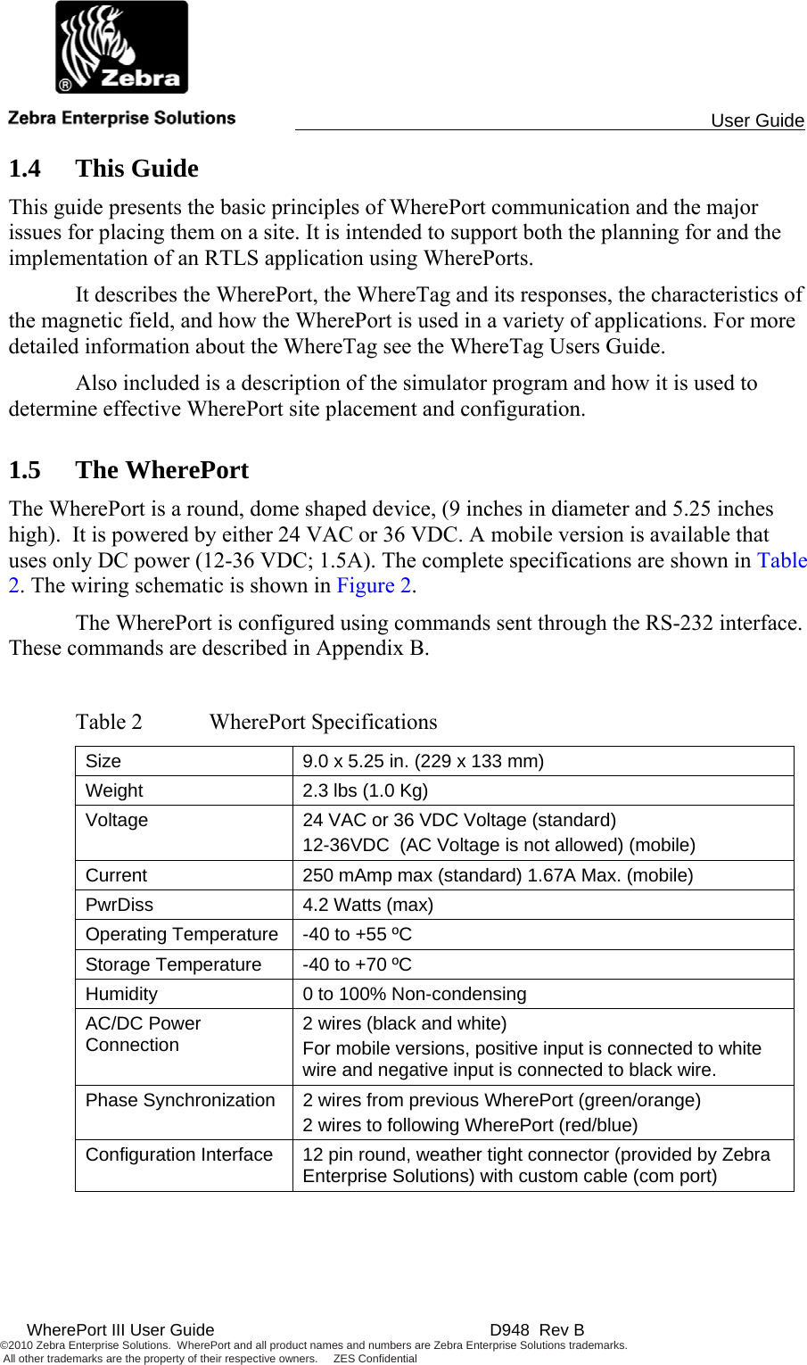
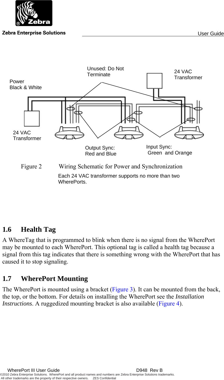
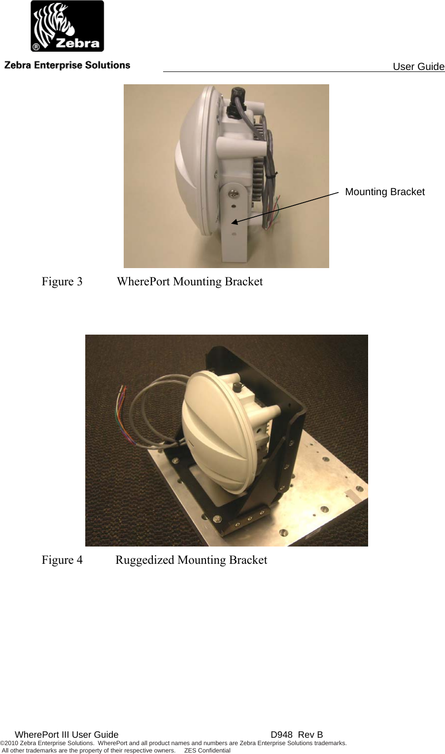
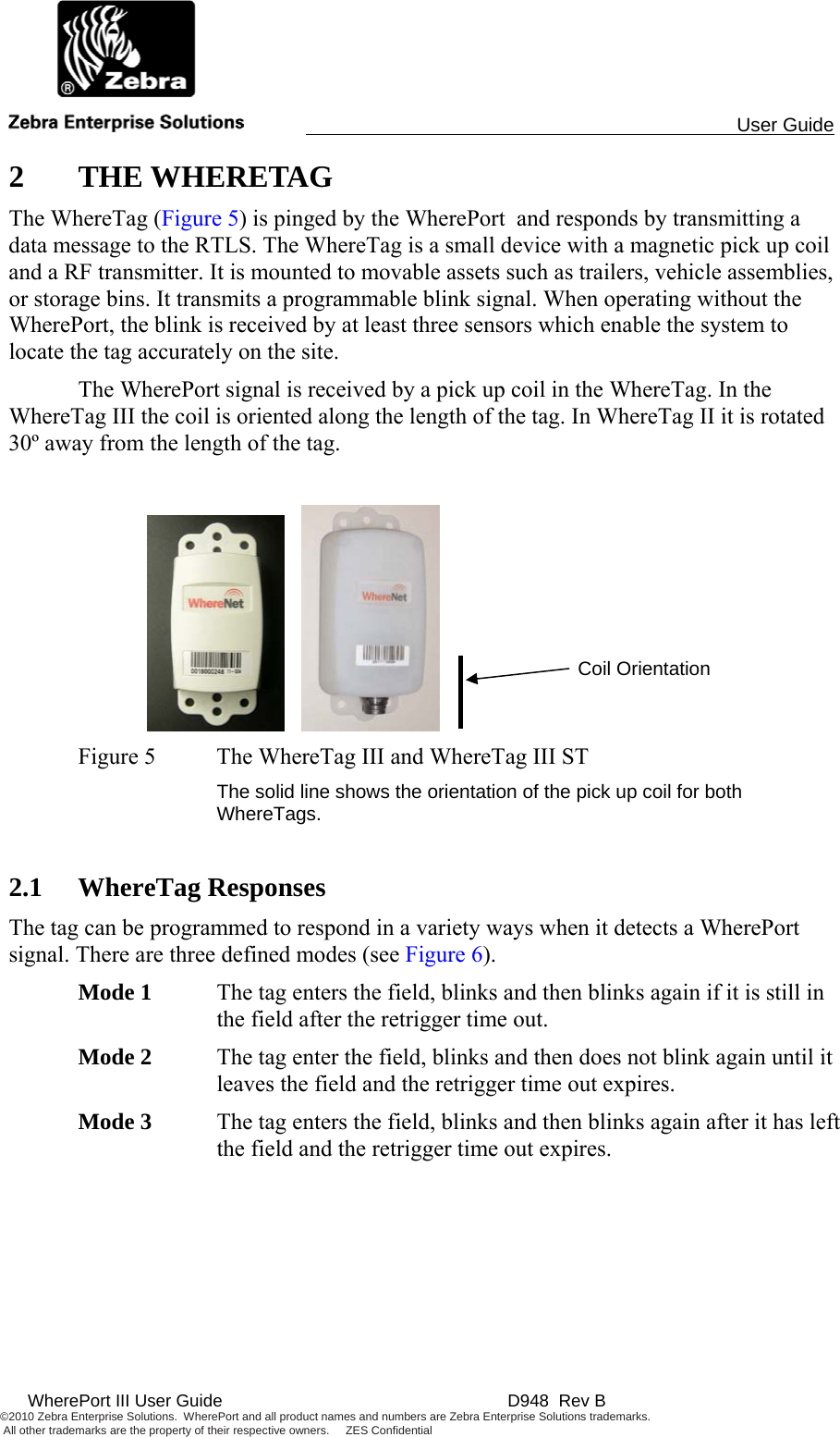
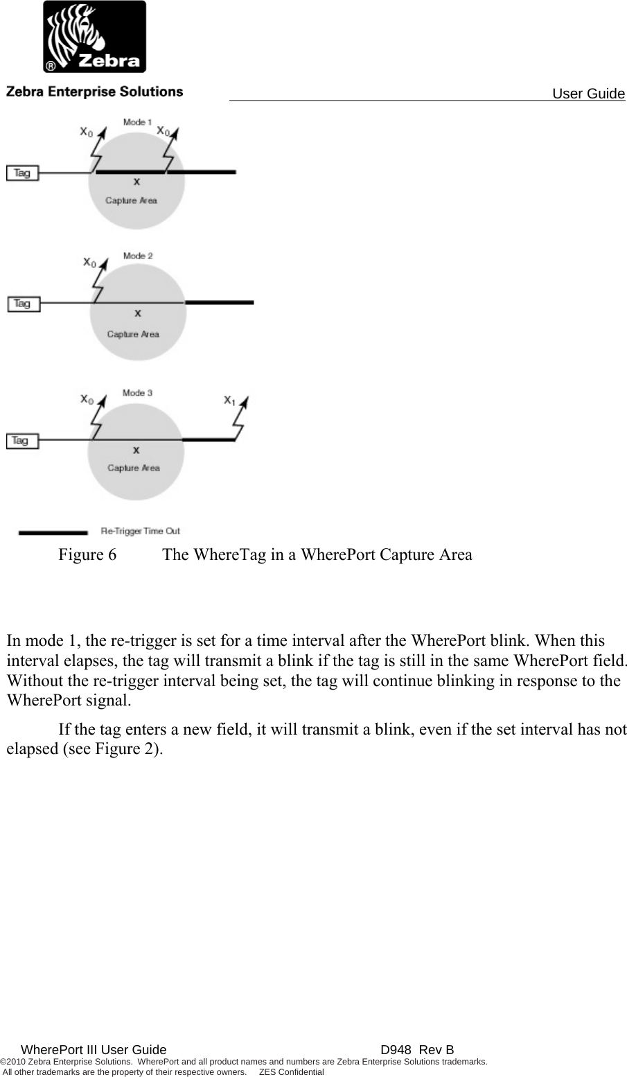
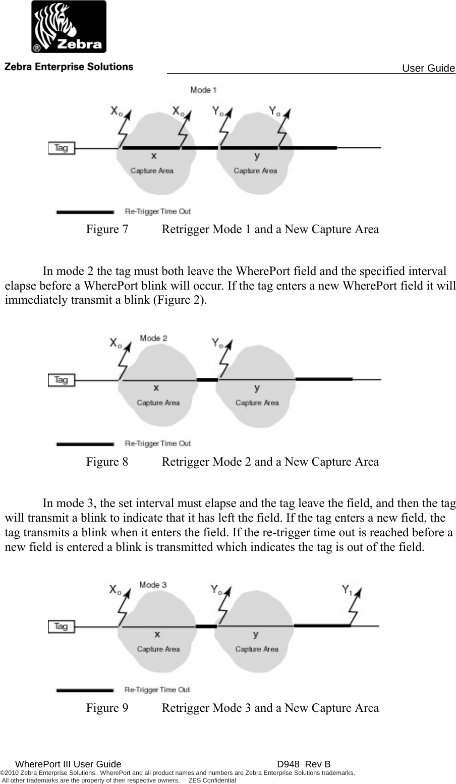
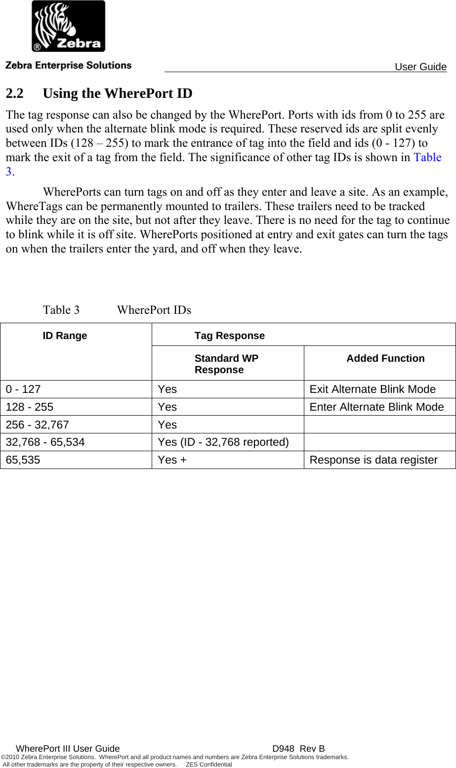
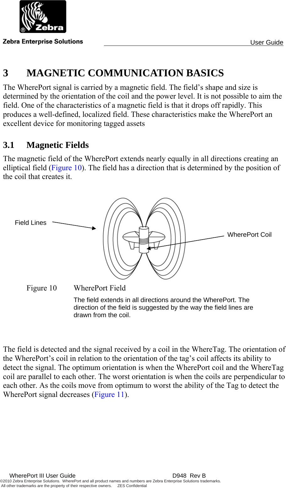
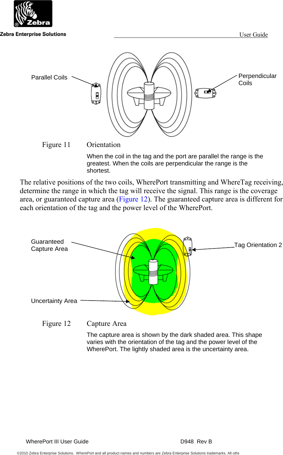
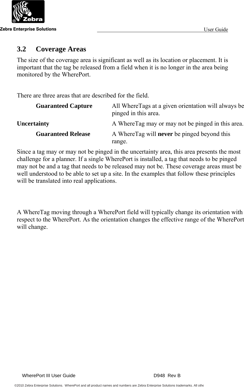
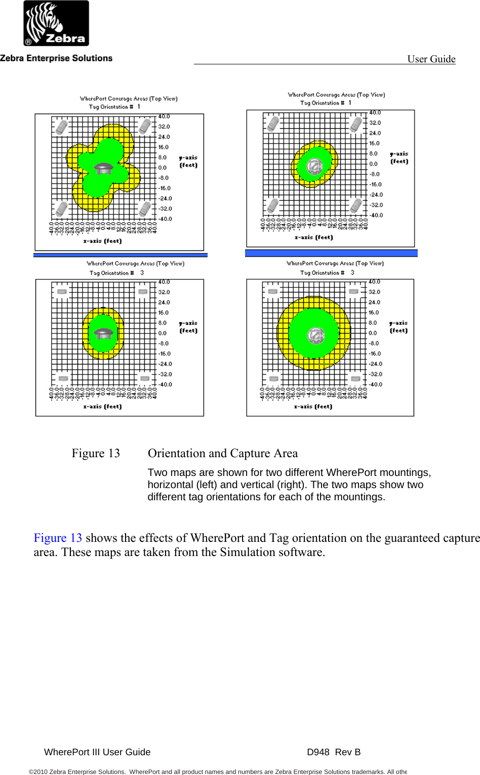
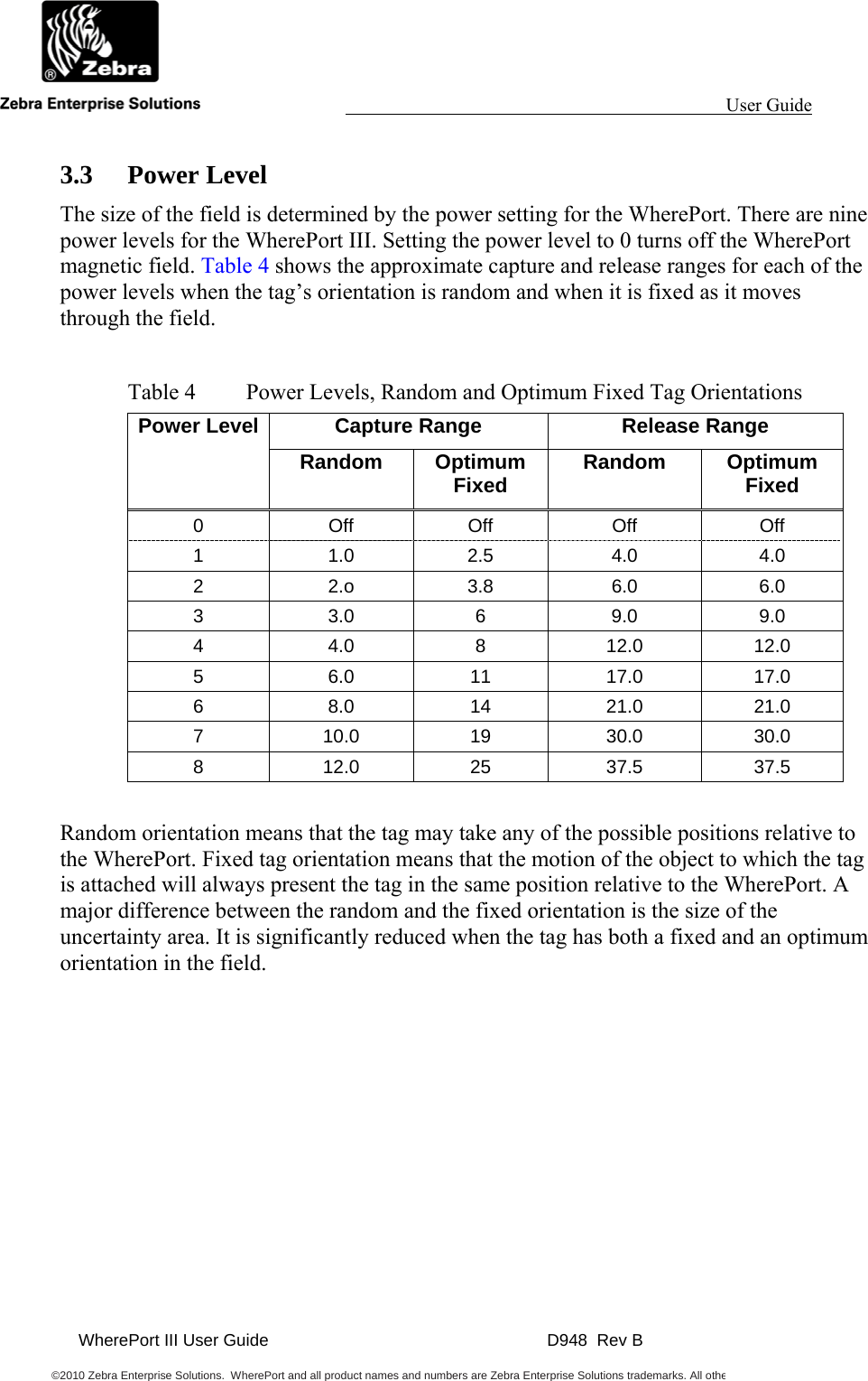
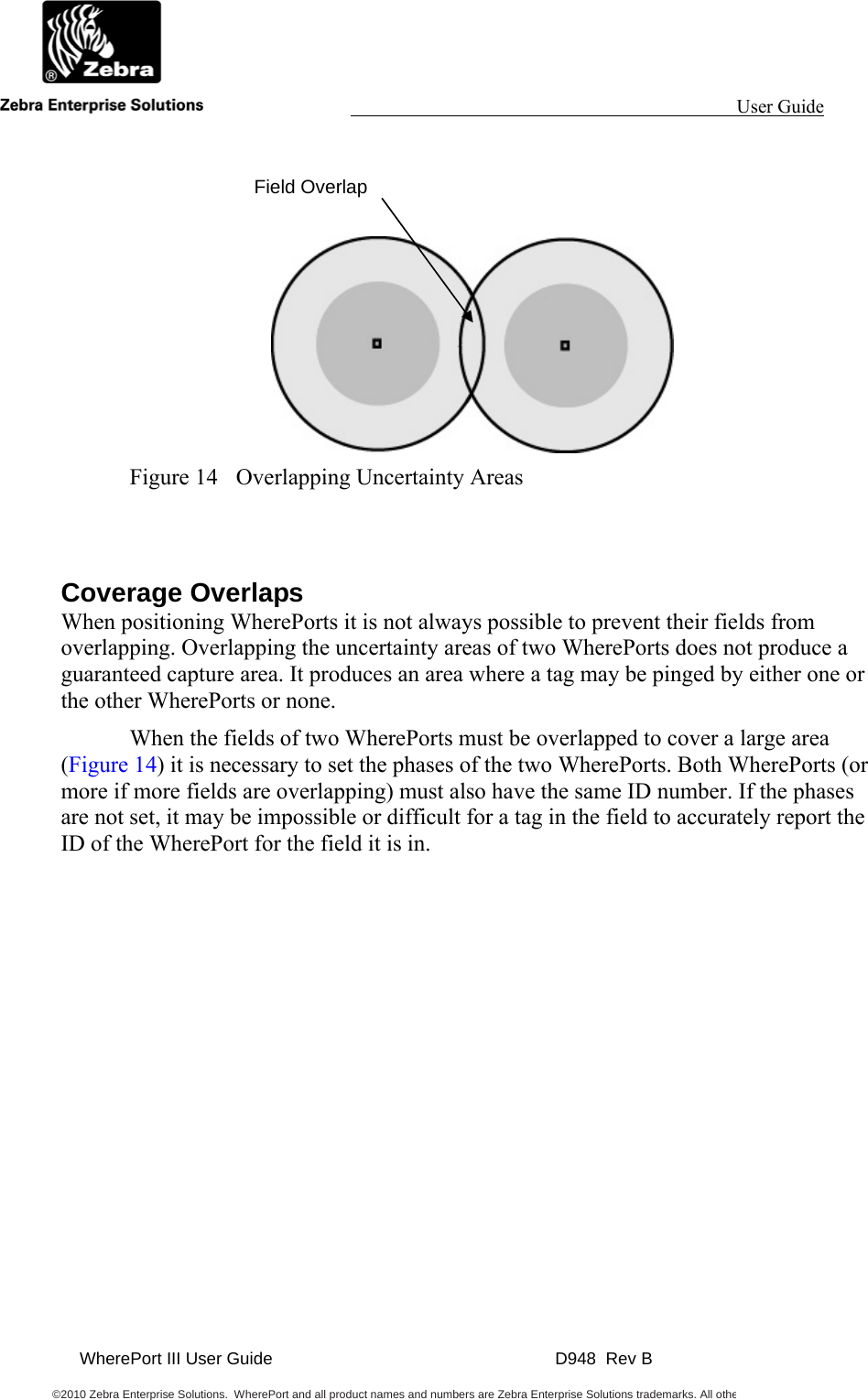
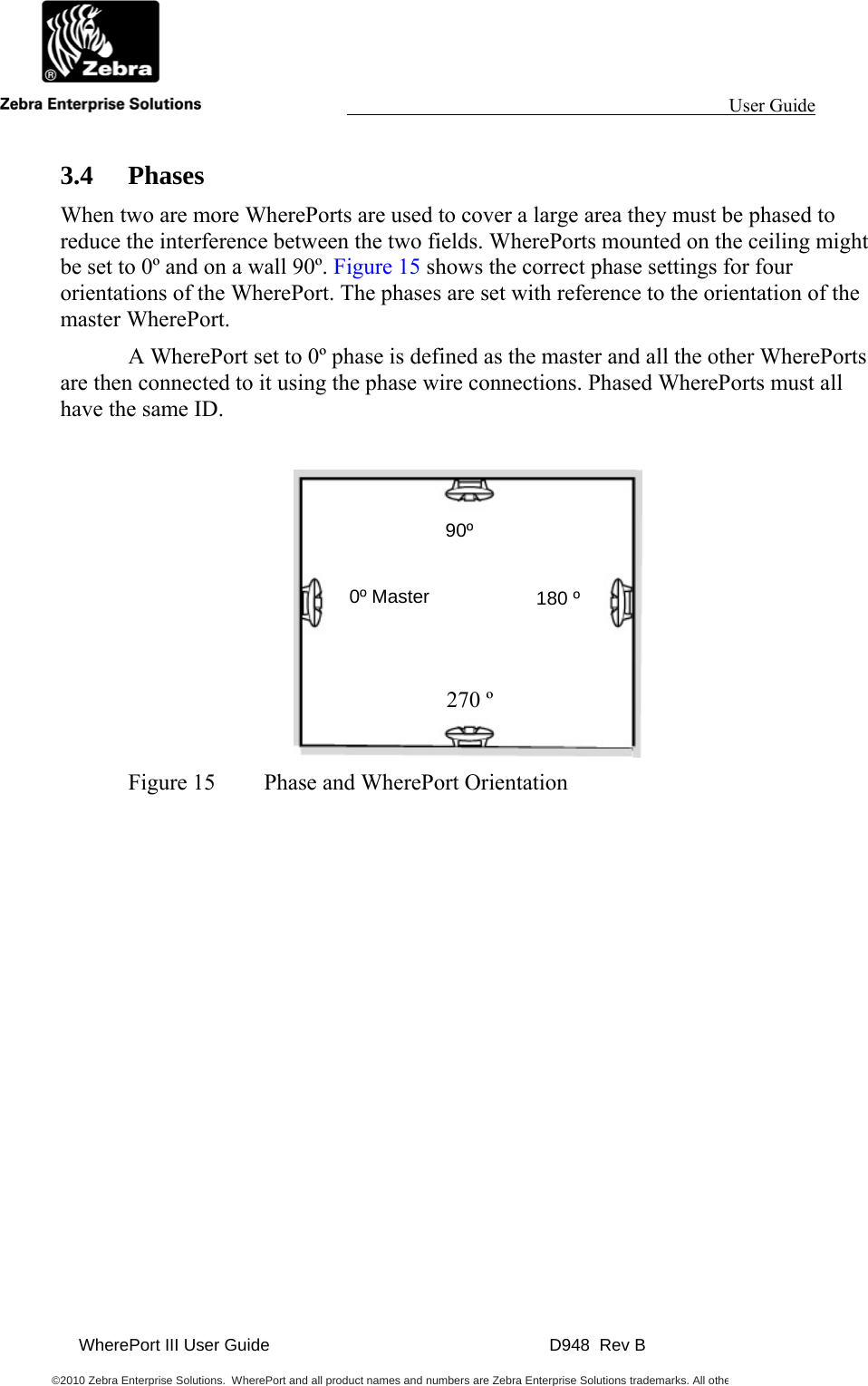
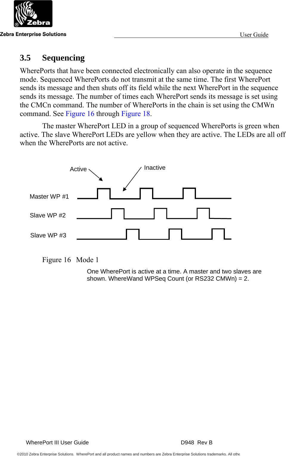
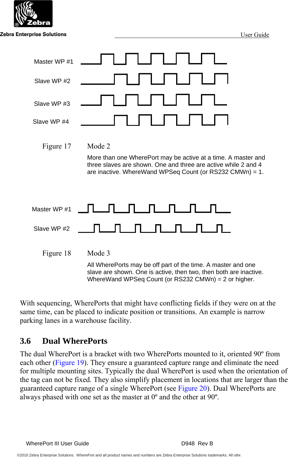
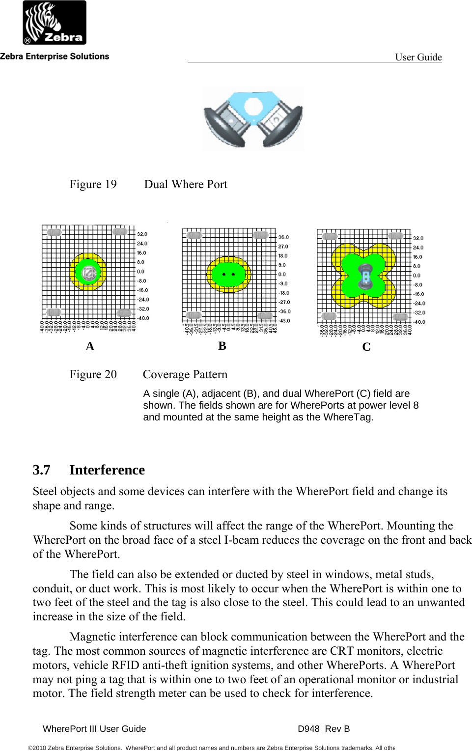
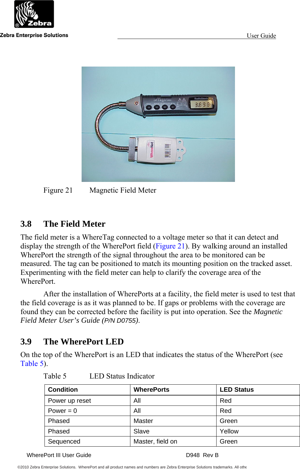
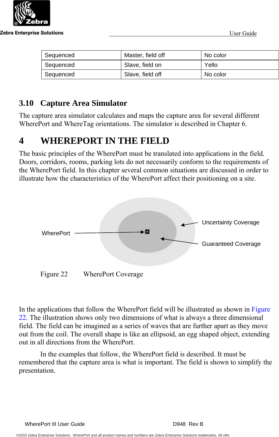
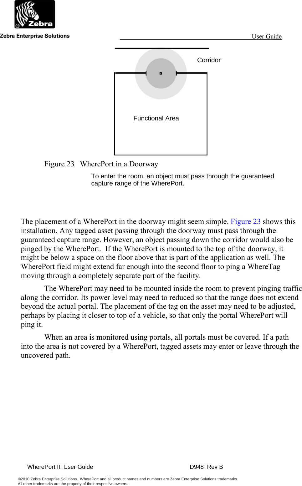
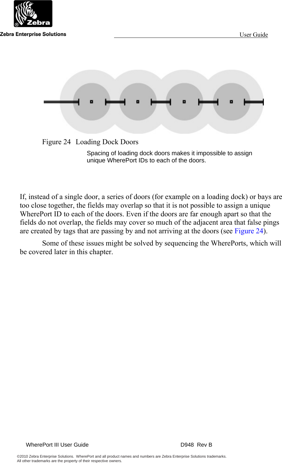
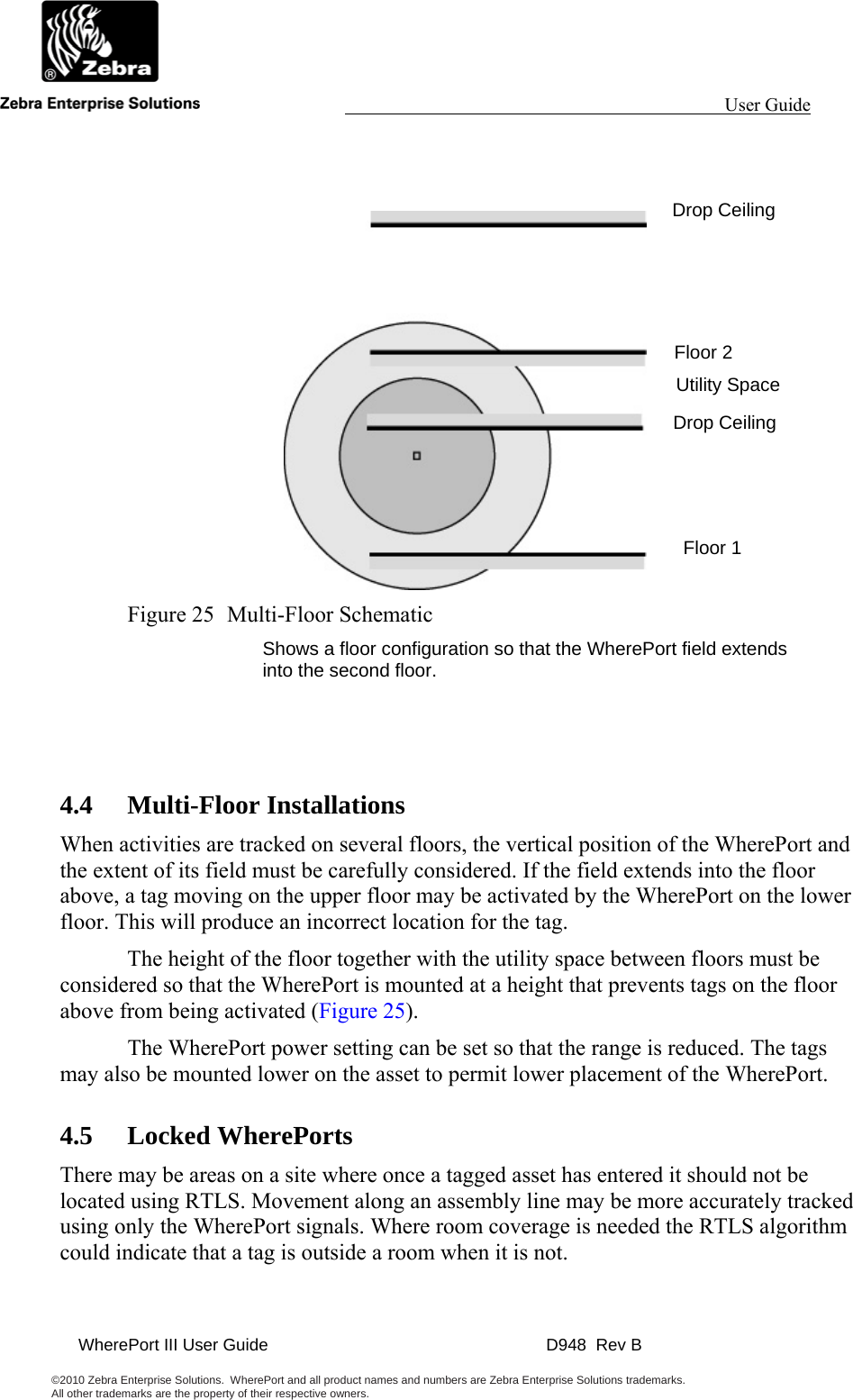
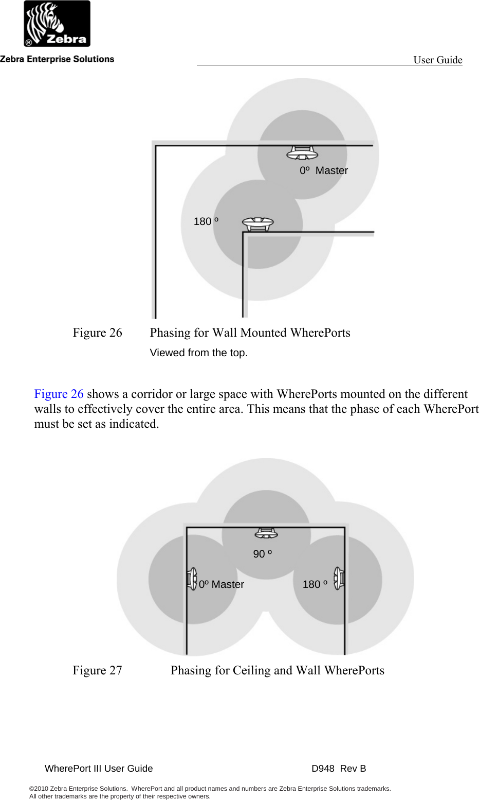
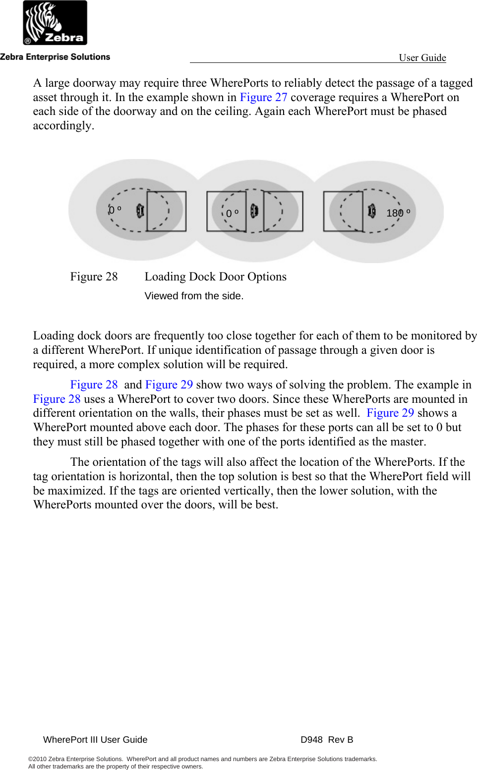
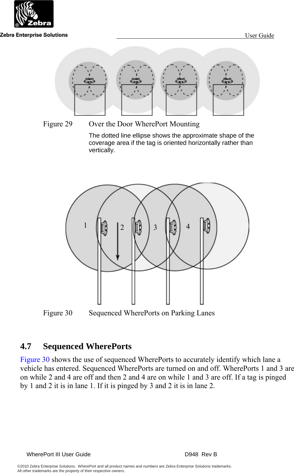

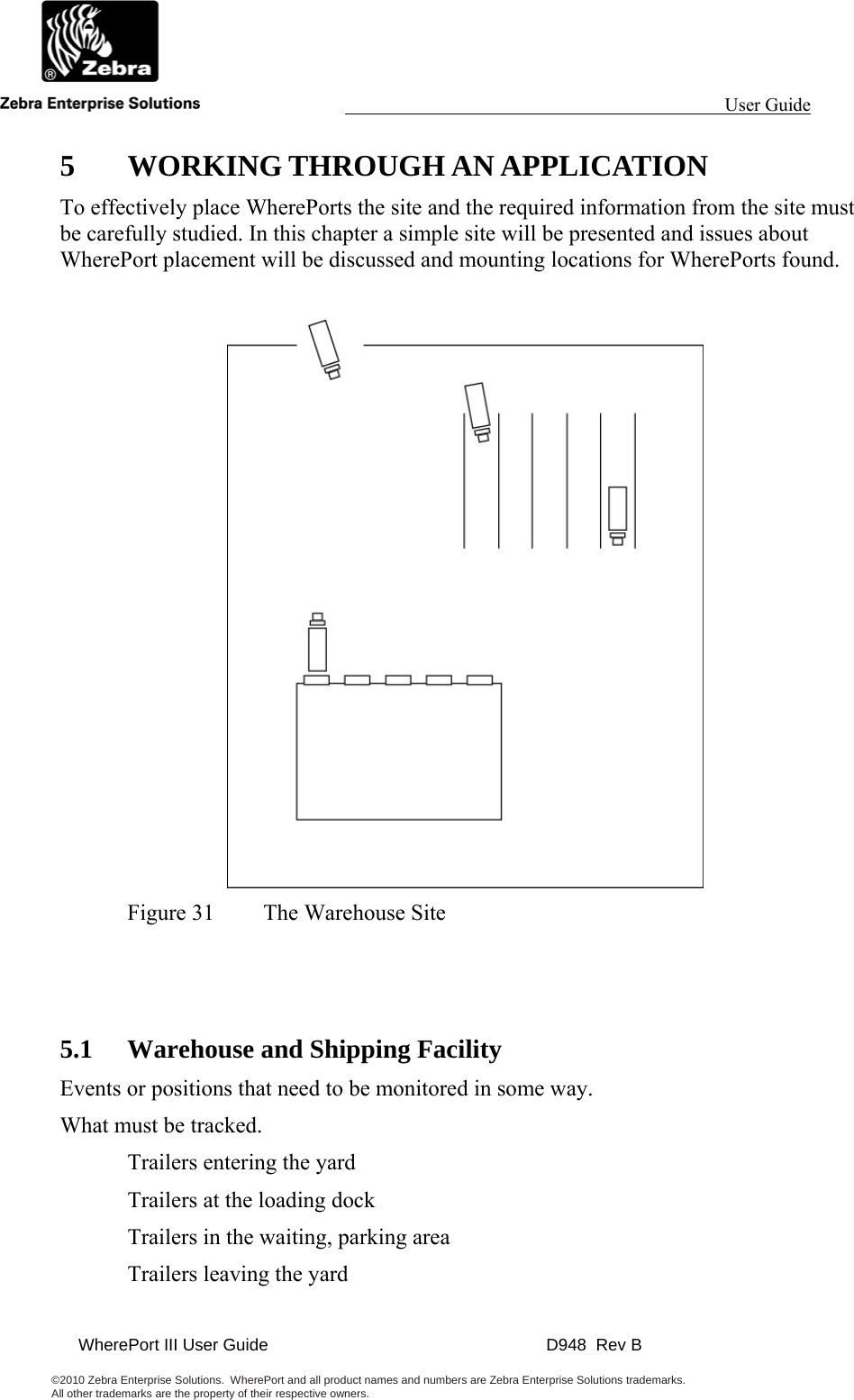
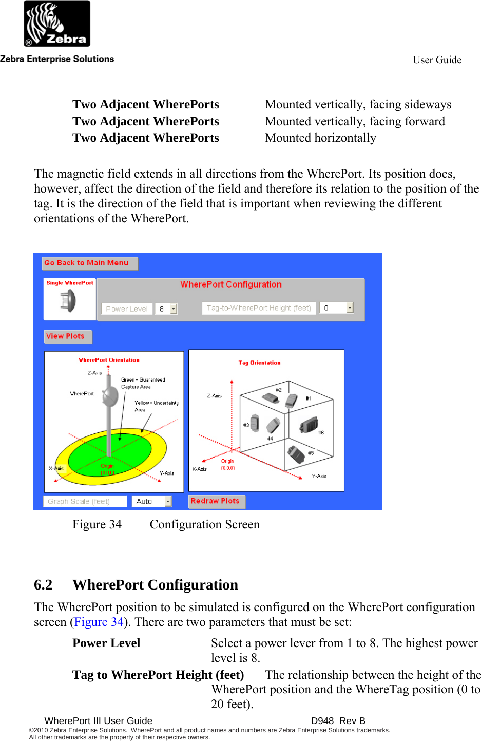
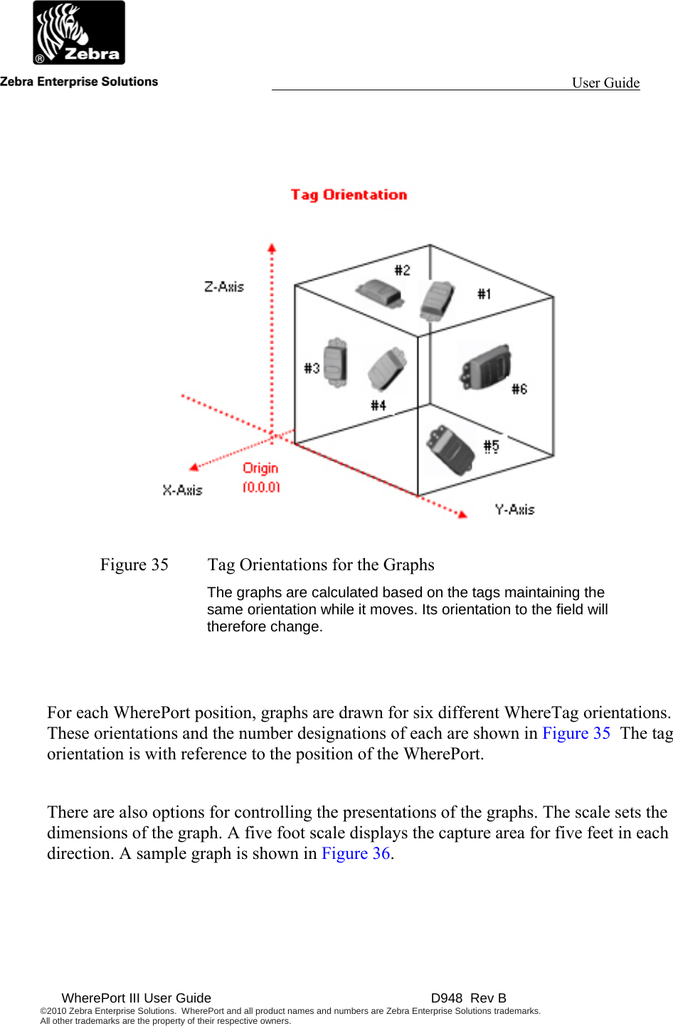
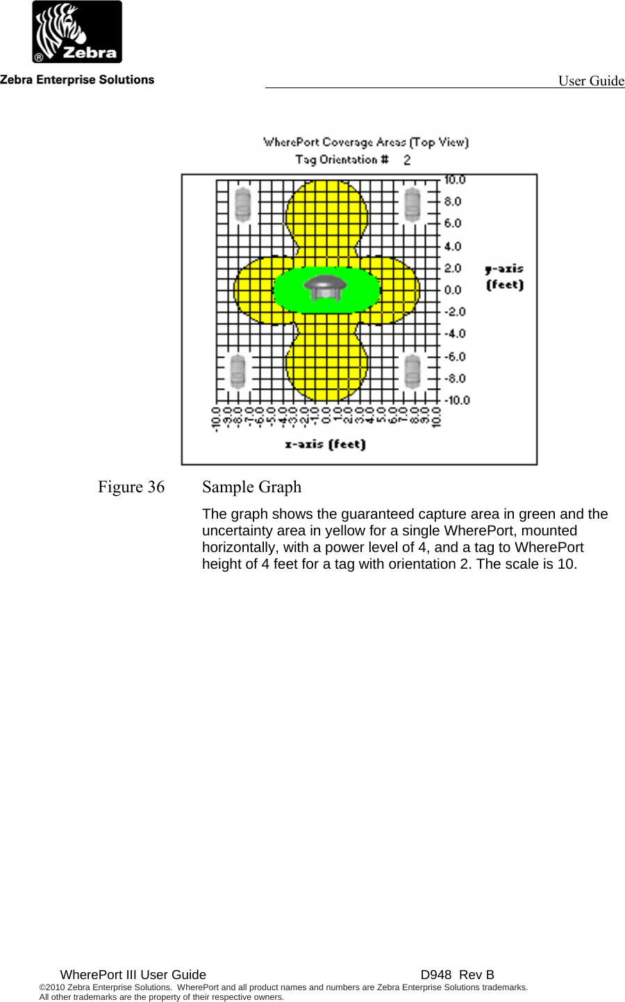
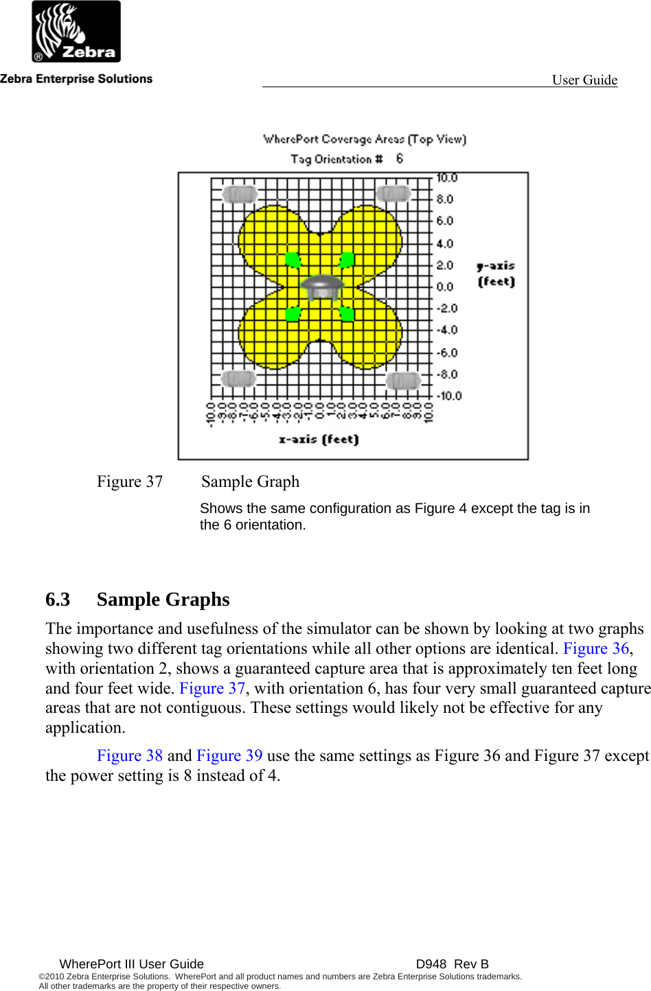

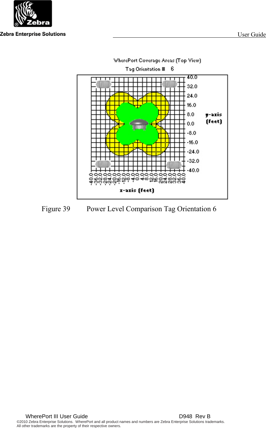
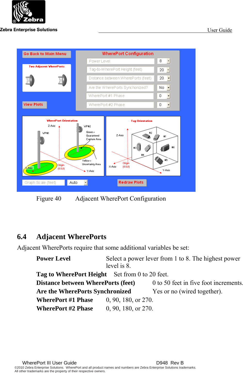
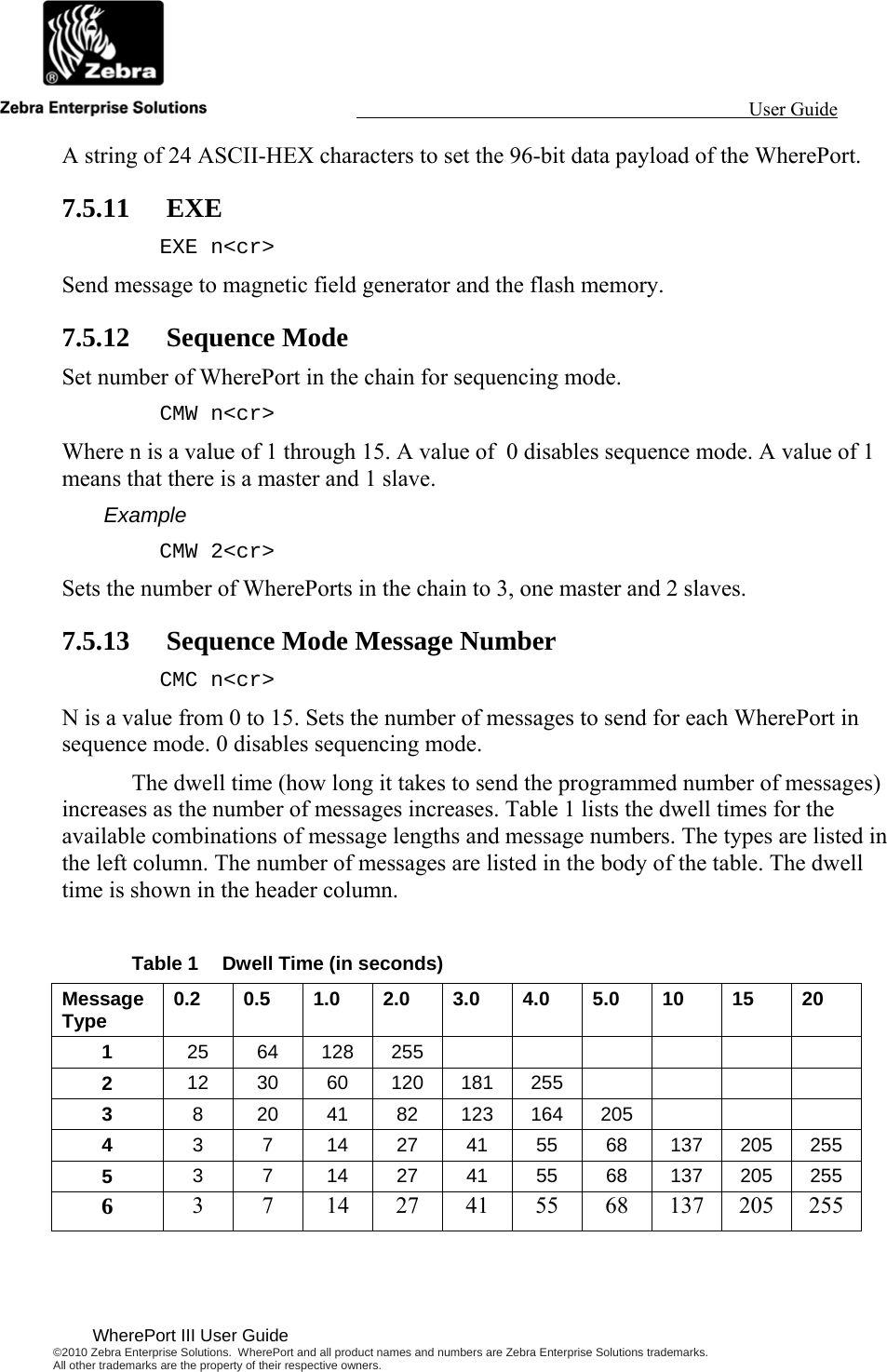
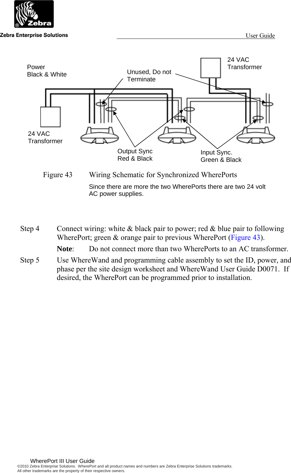
![User Guide WherePort III User Guide ©2010 Zebra Enterprise Solutions. WherePort and all product names and numbers are Zebra Enterprise Solutions trademarks. All other trademarks are the property of their respective owners. Example RSP 1<cr> Set the response blink type to 72 bits. 7.5.7 Count Set the WherePort response blink count (44 bit message only). CNT n<cr> Valid range for n is 0 through 15. Example CNT 4<cr> Sets the blink count to 4. 7.5.8 Interval Set the WherePort response blink interval (44 bit message only ) where n is 0 to 7. INT n<cr> 7.5.9 Trigger Set the re-trigger response (44 bit message only). TRG n<cr> Where n is a value 0 through 15. Example TRG 4<cr> Sets the re-trigger response to . 7.5.10 Data Set the 96 bit data payload (144 bit message only). DAT [string]<cr> String of 24 ASCII-HEX characters; set the 96 bit data payload (144 bit message only). String of 22 ASCII-HEX characters: set the 96 bit data payload, payload CRC automatically calculated (144 bit message only). Example DAT string<cr>](https://usermanual.wiki/Zebra-Technologies/WPT-3200.Users-Manual/User-Guide-1947839-Page-54.png)