Zebra Technologies WPT-3200 Proximity Communications Device User Manual
Zebra Technologies Corporation Proximity Communications Device Users Manual
Contents
Users Manual
User Guide
______________________________________________________________________________________ 1
WherePort III User Guide D948 Rev C
©2010 Zebra Enterprise Solutions. WherePort and all product names and numbers are Zebra Enterprise Solutions trademarks.
All other trademarks are the property of their respective owners. ZES Confidential
WherePort III User Guide
User Guide
______________________________________________________________________________________
2
WherePort III User Guide D948 Rev C
©2010 Zebra Enterprise Solutions. WherePort and all product names and numbers are Zebra Enterprise Solutions trademarks.
All other trademarks are the property of their respective owners. ZES Confidential
Typographical Conventions
Warnings call attention to a procedure or
practice that could result in personal injury if
not correctly performed. Do not proceed until
you fully understand and meet the required
conditions.
Cautions call attention to an operation
procedure or practice that could damage the
product if not correctly performed. Do not
proceed until understanding and meeting these
required conditions.
Notes provide information that can be helpful in
understanding the operation of the product.
_________
Note
_________
____________
CAUTION
____________
____________
____________

User Guide
______________________________________________________________________________________
3
WherePort III User Guide D948 Rev C
©2010 Zebra Enterprise Solutions. WherePort and all product names and numbers are Zebra Enterprise Solutions trademarks.
All other trademarks are the property of their respective owners. ZES Confidential
Document Revision History
Revision Change Description
Date Initials
A Release per ECO C01013 2/23/06 G.Phillips
B Updated per ECO C02336 12/07/10 D. Bowman

User Guide
______________________________________________________________________________________
4
WherePort III User Guide D948 Rev C
©2010 Zebra Enterprise Solutions. WherePort and all product names and numbers are Zebra Enterprise Solutions trademarks.
All other trademarks are the property of their respective owners. ZES Confidential
Contents
WherePort III User Guide .................................................................................... 1
1Regulatory Information ............................................................................... 6
1.1FCC and IC Requirements ........................................................................ 6
1.2EU Compliance Information (WPT-3200) ................................................. 6
1.3Regulatory - Other ..................................................................................... 7
CMIIT ID: 2007DJ4325The WherePort ............................................................... 7
The WherePort .................................................................................................... 8
1.4This Guide ................................................................................................. 9
1.5The WherePort........................................................................................... 9
1.6Health Tag ................................................................................................ 10
1.7WherePort Mounting ............................................................................... 10
2The WhereTag ............................................................................................ 12
2.1WhereTag Responses ............................................................................. 12
2.2Using the WherePort ID .......................................................................... 15
3Magnetic Communication Basics ............................................................. 16
3.1Magnetic Fields ....................................................................................... 16
3.2Coverage Areas ....................................................................................... 18
3.3Power Level ............................................................................................. 20
3.4Phases ..................................................................................................... 22
3.5Sequencing .............................................................................................. 23
3.6Dual WherePorts ..................................................................................... 24
3.7Interference ............................................................................................. 25
3.8The Field Meter ........................................................................................ 26
3.9The WherePort LED ................................................................................ 26
3.10Capture Area Simulator ....................................................................... 27
4WherePort in the Field ............................................................................... 27
4.1Zones ....................................................................................................... 28
4.2Area Coverage ......................................................................................... 28
4.3Portals ...................................................................................................... 28
4.4Multi-Floor Installations .......................................................................... 31
4.5Locked WherePorts ................................................................................ 31
4.6Multiple WherePorts ............................................................................... 32
4.7Sequenced WherePorts .......................................................................... 35
4.8Summary .................................................................................................. 36
5Working through an Application .............................................................. 38
5.1Warehouse and Shipping Facility .......................................................... 38
5.2Positioning the WherePorts ................................................................... 40
6Using the Simulator ................................................................................... 42

User Guide
______________________________________________________________________________________
5
WherePort III User Guide D948 Rev C
©2010 Zebra Enterprise Solutions. WherePort and all product names and numbers are Zebra Enterprise Solutions trademarks.
All other trademarks are the property of their respective owners. ZES Confidential
6.1Simulator Controls and Features ........................................................... 42
6.2WherePort Configuration ....................................................................... 43
6.3Sample Graphs ........................................................................................ 46
6.4Adjacent WherePorts .............................................................................. 49
7Command Summary .................................................................................. 50
7.1Initial Power Up ....................................................................................... 50
7.2Passwords ............................................................................................... 50
7.3Command Execution .............................................................................. 51
7.4Tag Responses to Commands ............................................................... 51
7.5Commands .............................................................................................. 52
7.5.1Message Length .......................................................................................... 52
7.5.2Power .......................................................................................................... 52
7.5.3Phase ........................................................................................................... 52
7.5.4WherePort ID .............................................................................................. 53
7.5.5Tag Id .......................................................................................................... 53
7.5.6Response ..................................................................................................... 53
7.5.7Count ........................................................................................................... 54
7.5.8Interval ........................................................................................................ 54
7.5.9Trigger......................................................................................................... 54
7.5.10Data ............................................................................................................. 54
7.5.11EXE ............................................................................................................. 55
7.5.12Sequence Mode ........................................................................................... 55
7.5.13Sequence Mode Message Number .............................................................. 55
7.5.14Version ........................................................................................................ 56
7.5.15XPW ............................................................................................................ 56
7.5.16HWT (1) ...................................................................................................... 56
7.5.17Loader ......................................................................................................... 56
7.5.18GQ ............................................................................................................... 56
8Installation .................................................................................................. 60
8.1WherePort Parts ...................................................................................... 60
8.2Also Required (not included) ................................................................. 61
8.3Installation Procedure ............................................................................ 62

User Guide
WherePort III User Guide D948 Rev B
©2010 Zebra Enterprise Solutions. WherePort and all product names and numbers are Zebra Enterprise Solutions trademarks.
All other trademarks are the property of their respective owners. ZES Confidential
1 REGULATORY INFORMATION
1.1 FCC and IC Requirements
This device complies with Part 15 rules. Operation is subject to the
following two conditions:
1. This device may not cause harmful interference, and
2. This device must accept any interference received, including
interference that may cause undesired operation. The user is
cautioned that any changes or modifications not expressly
approved by Zebra Enterprise Solutions could void the user’s
authority to operate the equipment.
See the FCC registration label, located on the bottom of the equipment for
the FCC registration and identity.
Canadian DOC Compliance Statement
ThisdevicecomplieswithIndustryCanadalicence‐exemptRSSstandard(s).
Operationissubjecttothefollowingtwoconditions:(1)thisdevicemaynot
causeinterference,and(2)thisdevicemustacceptanyinterference,including
interferencethatmaycauseundesiredoperationofthedevice.
LeprésentappareilestconformeauxCNRd'IndustrieCanadaapplicablesaux
appareilsradioexemptsdelicence.L'exploitationestautoriséeauxdeux
conditionssuivantes:(1)l'appareilnedoitpasproduiredebrouillage,et(2)
l'utilisateurdel'appareildoitacceptertoutbrouillageradioélectriquesubi,
mêmesilebrouillageestsusceptibled'encompromettrelefonctionnement.
1.2 EU Compliance Information (WPT-3200)
Table 1EU Compliance - Approved for use in the following countries
AT BE BG CY CZ DK EE
FI FR DE GR HU IE IT
LV LT LU MT NL PL PT
RO SK SI ES SE GB
IS LI NO CH
User Guide
WherePort III User Guide D948 Rev B
©2010 Zebra Enterprise Solutions. WherePort and all product names and numbers are Zebra Enterprise Solutions trademarks.
All other trademarks are the property of their respective owners. ZES Confidential
1.3 Regulatory - Other
CMIIT ID: 2007DJ4325
User Guide
WherePort III User Guide D948 Rev B
©2010 Zebra Enterprise Solutions. WherePort and all product names and numbers are Zebra Enterprise Solutions trademarks.
All other trademarks are the property of their respective owners. ZES Confidential
THE WHEREPORT
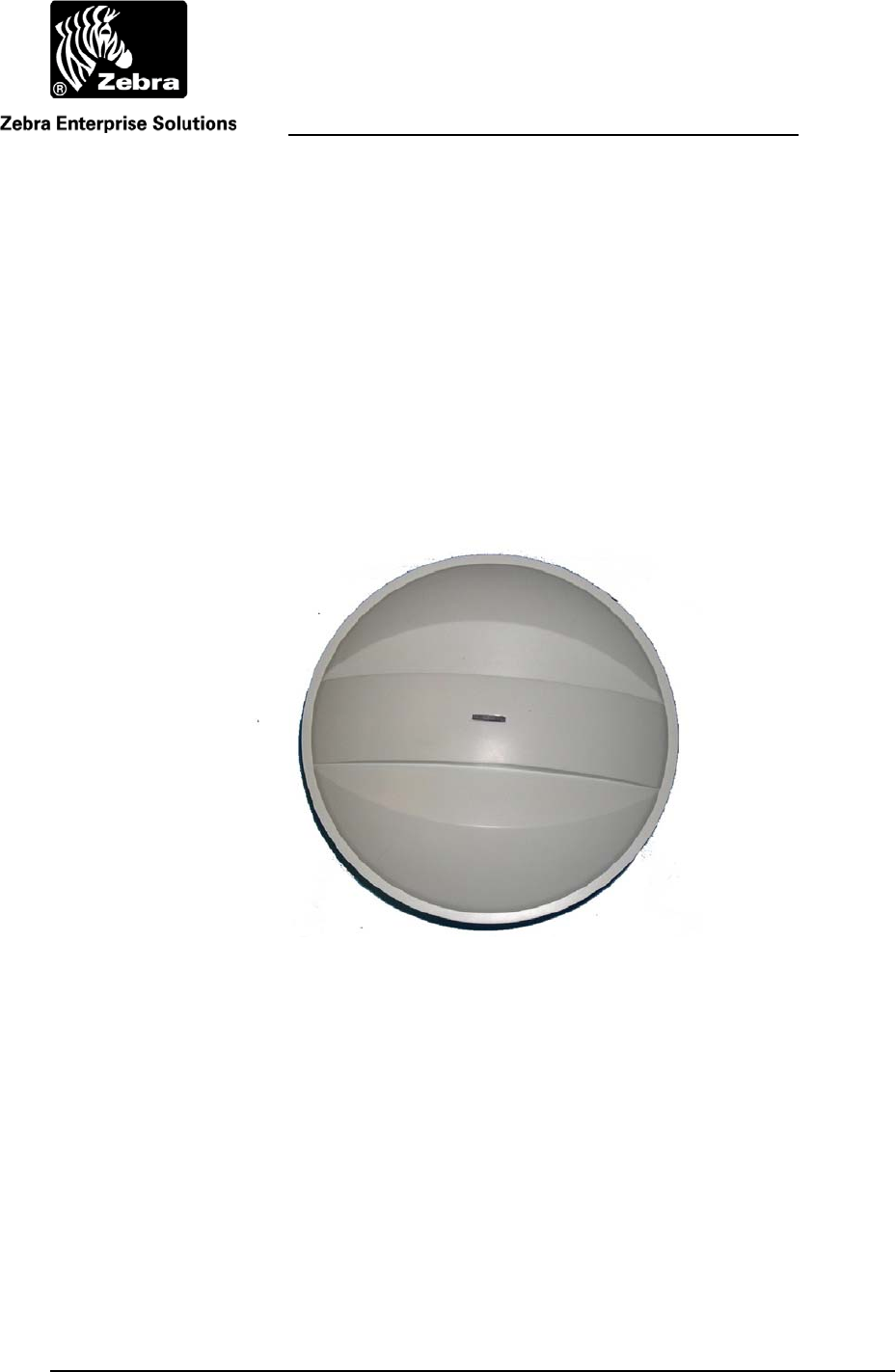
The WherePort III is a location indicator that is part of the Zebra Enterprise Solutions
(ZES) Real Time Locating System (Figure 1). The WherePort transmits a localized
magnetic field. Since the field is confined (programmable from approximately 3 feet to
25 feet) it is a reliable indicator of the location of key sites in the facility. When
WhereTags pass through the WherePort field they transmit the ID of the WherePort. The
WhereTag response can be programmed to indicate needed information about the status
of the asset or object to which the tag is attached.
WherePorts are mounted to fixed locations such as gates, loading docks, or cells
along an assembly line so that information required about the movement of assets
through the facility will be gathered by the RTLS. As tagged assets pass through the
fields the tag transmits the WherePort ID that pinged it and any other programmed status
information.
Figure 1 WherePort
The VSS system is programmed with the location of each WherePort and their ID. When
a WhereTag transmits a message that includes the ID of the WherePort field that it is in,
the system knows where the WhereTag is. This is particularly important when locating
transitions is important or where the layout of the site makes it difficult to have enough
sensors to accurately locate the tag using RTLS.
Status LED

User Guide
WherePort III User Guide D948 Rev B
©2010 Zebra Enterprise Solutions. WherePort and all product names and numbers are Zebra Enterprise Solutions trademarks.
All other trademarks are the property of their respective owners. ZES Confidential
1.4 This Guide
This guide presents the basic principles of WherePort communication and the major
issues for placing them on a site. It is intended to support both the planning for and the
implementation of an RTLS application using WherePorts.
It describes the WherePort, the WhereTag and its responses, the characteristics of
the magnetic field, and how the WherePort is used in a variety of applications. For more
detailed information about the WhereTag see the WhereTag Users Guide.
Also included is a description of the simulator program and how it is used to
determine effective WherePort site placement and configuration.
1.5 The WherePort
The WherePort is a round, dome shaped device, (9 inches in diameter and 5.25 inches
high). It is powered by either 24 VAC or 36 VDC. A mobile version is available that
uses only DC power (12-36 VDC; 1.5A). The complete specifications are shown in Table
2. The wiring schematic is shown in Figure 2.
The WherePort is configured using commands sent through the RS-232 interface.
These commands are described in Appendix B.
Table 2 WherePort Specifications
Size 9.0 x 5.25 in. (229 x 133 mm)
Weight 2.3 lbs (1.0 Kg)
Voltage 24 VAC or 36 VDC Voltage (standard)
12-36VDC (AC Voltage is not allowed) (mobile)
Current 250 mAmp max (standard) 1.67A Max. (mobile)
PwrDiss 4.2 Watts (max)
Operating Temperature -40 to +55 ºC
Storage Temperature -40 to +70 ºC
Humidity 0 to 100% Non-condensing
AC/DC Power
Connection 2 wires (black and white)
For mobile versions, positive input is connected to white
wire and negative input is connected to black wire.
Phase Synchronization 2 wires from previous WherePort (green/orange)
2 wires to following WherePort (red/blue)
Configuration Interface 12 pin round, weather tight connector (provided by Zebra
Enterprise Solutions) with custom cable (com port)
User Guide
WherePort III User Guide D948 Rev B
©2010 Zebra Enterprise Solutions. WherePort and all product names and numbers are Zebra Enterprise Solutions trademarks.
All other trademarks are the property of their respective owners. ZES Confidential
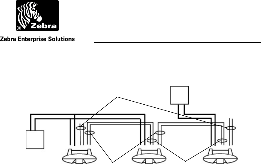
Figure 2 Wiring Schematic for Power and Synchronization
Each 24 VAC transformer supports no more than two
WherePorts.
1.6 Health Tag
A WhereTag that is programmed to blink when there is no signal from the WherePort
may be mounted to each WherePort. This optional tag is called a health tag because a
signal from this tag indicates that there is something wrong with the WherePort that has
caused it to stop signaling.
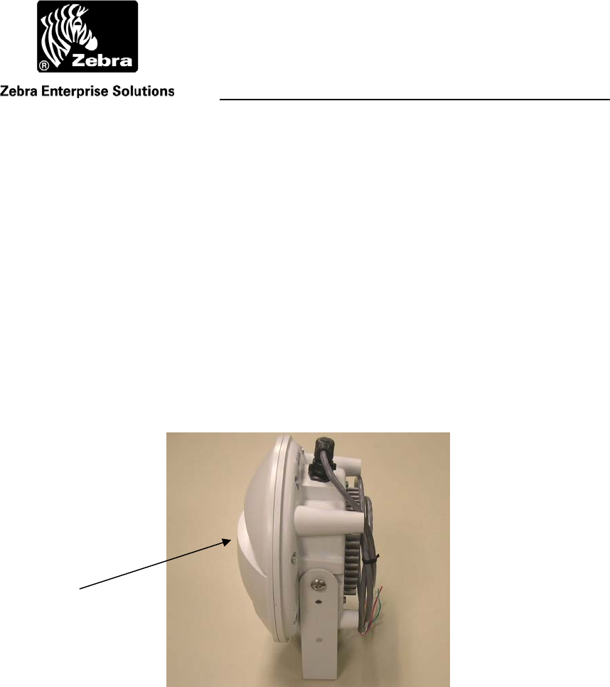
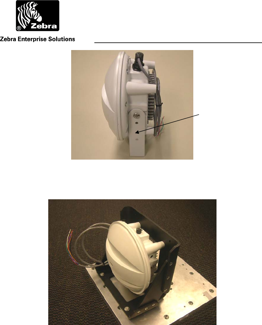
1.7 WherePort Mounting
The WherePort is mounted using a bracket (Figure 3). It can be mounted from the back,
the top, or the bottom. For details on installing the WherePort see the Installation
Instructions. A ruggedized mounting bracket is also available (Figure 4).
24 VAC
Transformer
Power
Black & White
Unused: Do Not
Terminate
Output Sync:
Red and Blue
Input Sync:
Green and Orange
24 VAC
Transformer
User Guide
WherePort III User Guide D948 Rev B
©2010 Zebra Enterprise Solutions. WherePort and all product names and numbers are Zebra Enterprise Solutions trademarks.
All other trademarks are the property of their respective owners. ZES Confidential
Figure 3 WherePort Mounting Bracket
Figure 4 Ruggedized Mounting Bracket
Mounting Bracket
User Guide
WherePort III User Guide D948 Rev B
©2010 Zebra Enterprise Solutions. WherePort and all product names and numbers are Zebra Enterprise Solutions trademarks.
All other trademarks are the property of their respective owners. ZES Confidential
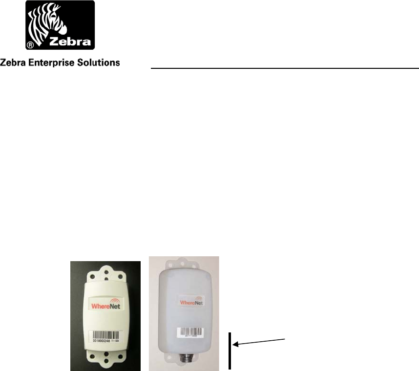
2 THE WHERETAG
The WhereTag (Figure 5) is pinged by the WherePort and responds by transmitting a
data message to the RTLS. The WhereTag is a small device with a magnetic pick up coil
and a RF transmitter. It is mounted to movable assets such as trailers, vehicle assemblies,
or storage bins. It transmits a programmable blink signal. When operating without the
WherePort, the blink is received by at least three sensors which enable the system to
locate the tag accurately on the site.
The WherePort signal is received by a pick up coil in the WhereTag. In the
WhereTag III the coil is oriented along the length of the tag. In WhereTag II it is rotated
30º away from the length of the tag.
Figure 5 The WhereTag III and WhereTag III ST
The solid line shows the orientation of the pick up coil for both
WhereTags.
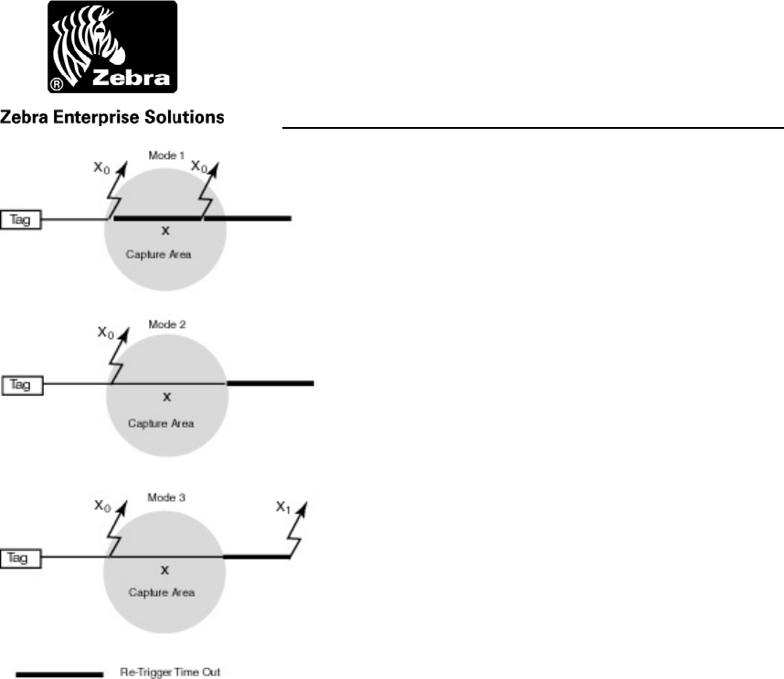
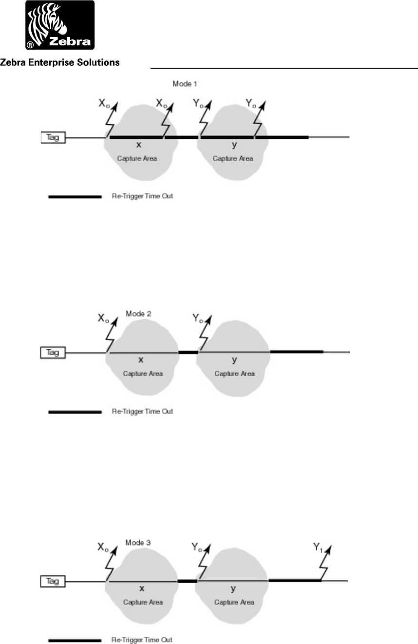
2.1 WhereTag Responses
The tag can be programmed to respond in a variety ways when it detects a WherePort
signal. There are three defined modes (see Figure 6).
Mode 1 The tag enters the field, blinks and then blinks again if it is still in
the field after the retrigger time out.
Mode 2 The tag enter the field, blinks and then does not blink again until it
leaves the field and the retrigger time out expires.
Mode 3 The tag enters the field, blinks and then blinks again after it has left
the field and the retrigger time out expires.
Coil Orientation
User Guide
WherePort III User Guide D948 Rev B
©2010 Zebra Enterprise Solutions. WherePort and all product names and numbers are Zebra Enterprise Solutions trademarks.
All other trademarks are the property of their respective owners. ZES Confidential
Figure 6 The WhereTag in a WherePort Capture Area
In mode 1, the re-trigger is set for a time interval after the WherePort blink. When this
interval elapses, the tag will transmit a blink if the tag is still in the same WherePort field.
Without the re-trigger interval being set, the tag will continue blinking in response to the
WherePort signal.
If the tag enters a new field, it will transmit a blink, even if the set interval has not
elapsed (see Figure 2).
User Guide
WherePort III User Guide D948 Rev B
©2010 Zebra Enterprise Solutions. WherePort and all product names and numbers are Zebra Enterprise Solutions trademarks.
All other trademarks are the property of their respective owners. ZES Confidential
Figure 7 Retrigger Mode 1 and a New Capture Area
In mode 2 the tag must both leave the WherePort field and the specified interval
elapse before a WherePort blink will occur. If the tag enters a new WherePort field it will
immediately transmit a blink (Figure 2).
Figure 8 Retrigger Mode 2 and a New Capture Area
In mode 3, the set interval must elapse and the tag leave the field, and then the tag
will transmit a blink to indicate that it has left the field. If the tag enters a new field, the
tag transmits a blink when it enters the field. If the re-trigger time out is reached before a
new field is entered a blink is transmitted which indicates the tag is out of the field.
Figure 9 Retrigger Mode 3 and a New Capture Area

User Guide
WherePort III User Guide D948 Rev B
©2010 Zebra Enterprise Solutions. WherePort and all product names and numbers are Zebra Enterprise Solutions trademarks.
All other trademarks are the property of their respective owners. ZES Confidential
2.2 Using the WherePort ID
The tag response can also be changed by the WherePort. Ports with ids from 0 to 255 are
used only when the alternate blink mode is required. These reserved ids are split evenly
between IDs (128 – 255) to mark the entrance of tag into the field and ids (0 - 127) to
mark the exit of a tag from the field. The significance of other tag IDs is shown in Table
3.
WherePorts can turn tags on and off as they enter and leave a site. As an example,
WhereTags can be permanently mounted to trailers. These trailers need to be tracked
while they are on the site, but not after they leave. There is no need for the tag to continue
to blink while it is off site. WherePorts positioned at entry and exit gates can turn the tags
on when the trailers enter the yard, and off when they leave.
Table 3 WherePort IDs
ID Range Tag Response
Standard WP
Response Added Function
0 - 127 Yes Exit Alternate Blink Mode
128 - 255 Yes Enter Alternate Blink Mode
256 - 32,767 Yes
32,768 - 65,534 Yes (ID - 32,768 reported)
65,535 Yes + Response is data register
User Guide
WherePort III User Guide D948 Rev B
©2010 Zebra Enterprise Solutions. WherePort and all product names and numbers are Zebra Enterprise Solutions trademarks.
All other trademarks are the property of their respective owners. ZES Confidential
3 MAGNETIC COMMUNICATION BASICS
The WherePort signal is carried by a magnetic field. The field’s shape and size is
determined by the orientation of the coil and the power level. It is not possible to aim the
field. One of the characteristics of a magnetic field is that it drops off rapidly. This
produces a well-defined, localized field. These characteristics make the WherePort an
excellent device for monitoring tagged assets
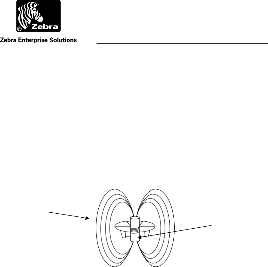
3.1 Magnetic Fields
The magnetic field of the WherePort extends nearly equally in all directions creating an
elliptical field (Figure 10). The field has a direction that is determined by the position of
the coil that creates it.
Figure 10 WherePort Field
The field extends in all directions around the WherePort. The
direction of the field is suggested by the way the field lines are
drawn from the coil.
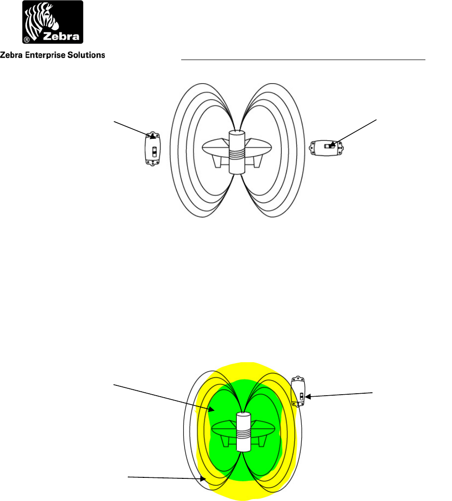
The field is detected and the signal received by a coil in the WhereTag. The orientation of
the WherePort’s coil in relation to the orientation of the tag’s coil affects its ability to
detect the signal. The optimum orientation is when the WherePort coil and the WhereTag
coil are parallel to each other. The worst orientation is when the coils are perpendicular to
each other. As the coils move from optimum to worst the ability of the Tag to detect the
WherePort signal decreases (Figure 11).
WherePort Coil
Field Lines
User Guide
WherePort III User Guide D948 Rev B
©2010 Zebra Enterprise Solutions. WherePort and all product names and numbers are Zebra Enterprise Solutions trademarks. All oth
e
Figure 11 Orientation
When the coil in the tag and the port are parallel the range is the
greatest. When the coils are perpendicular the range is the
shortest.
The relative positions of the two coils, WherePort transmitting and WhereTag receiving,
determine the range in which the tag will receive the signal. This range is the coverage
area, or guaranteed capture area (Figure 12). The guaranteed capture area is different for
each orientation of the tag and the power level of the WherePort.
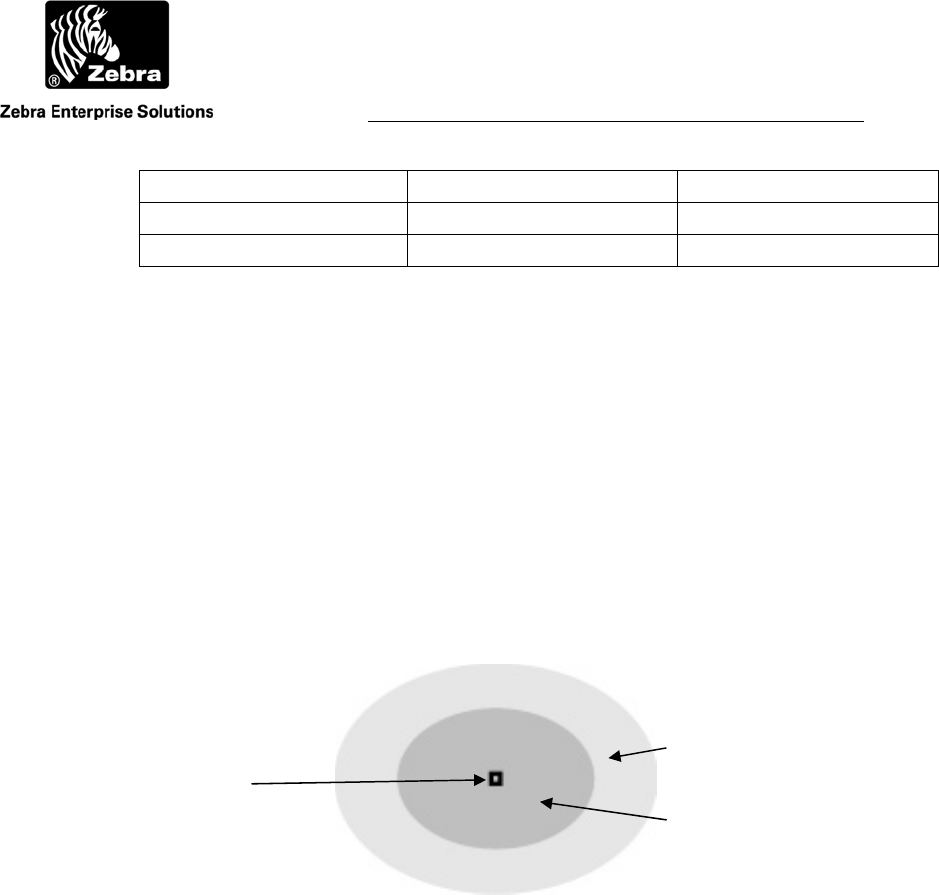
Figure 12 Capture Area
The capture area is shown by the dark shaded area. This shape
varies with the orientation of the tag and the power level of the
WherePort. The lightly shaded area is the uncertainty area.
Tag Orientation 2
Parallel Coils Perpendicular
Coils
Guaranteed
Capture Area
Uncertainty Area

User Guide
WherePort III User Guide D948 Rev B
©2010 Zebra Enterprise Solutions. WherePort and all product names and numbers are Zebra Enterprise Solutions trademarks. All oth
e
3.2 Coverage Areas
The size of the coverage area is significant as well as its location or placement. It is
important that the tag be released from a field when it is no longer in the area being
monitored by the WherePort.
There are three areas that are described for the field.
Guaranteed Capture All WhereTags at a given orientation will always be
pinged in this area.
Uncertainty A WhereTag may or may not be pinged in this area.
Guaranteed Release A WhereTag will never be pinged beyond this
range.
Since a tag may or may not be pinged in the uncertainty area, this area presents the most
challenge for a planner. If a single WherePort is installed, a tag that needs to be pinged
may not be and a tag that needs to be released may not be. These coverage areas must be
well understood to be able to set up a site. In the examples that follow these principles
will be translated into real applications.
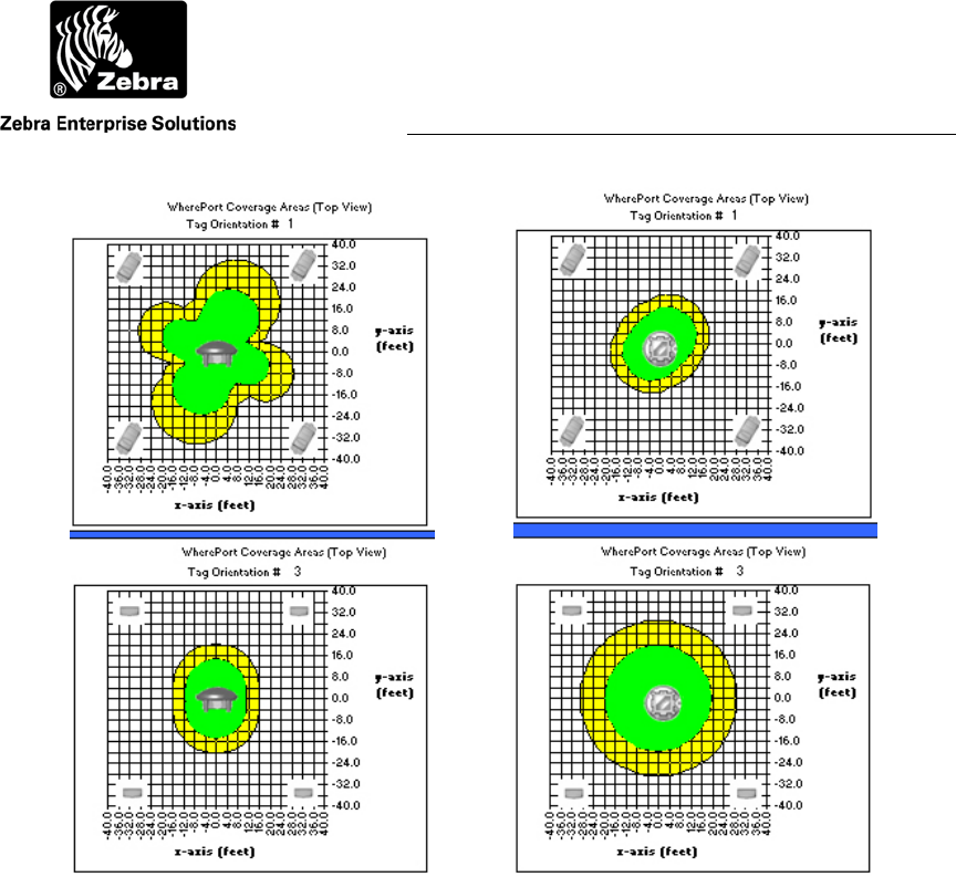
A WhereTag moving through a WherePort field will typically change its orientation with
respect to the WherePort. As the orientation changes the effective range of the WherePort
will change.
User Guide
WherePort III User Guide D948 Rev B
©2010 Zebra Enterprise Solutions. WherePort and all product names and numbers are Zebra Enterprise Solutions trademarks. All oth
e
Figure 13 Orientation and Capture Area
Two maps are shown for two different WherePort mountings,
horizontal (left) and vertical (right). The two maps show two
different tag orientations for each of the mountings.
Figure 13 shows the effects of WherePort and Tag orientation on the guaranteed capture
area. These maps are taken from the Simulation software.

User Guide
WherePort III User Guide D948 Rev B
©2010 Zebra Enterprise Solutions. WherePort and all product names and numbers are Zebra Enterprise Solutions trademarks. All oth
e
3.3 Power Level
The size of the field is determined by the power setting for the WherePort. There are nine
power levels for the WherePort III. Setting the power level to 0 turns off the WherePort
magnetic field. Table 4 shows the approximate capture and release ranges for each of the
power levels when the tag’s orientation is random and when it is fixed as it moves
through the field.
Table 4 Power Levels, Random and Optimum Fixed Tag Orientations
Power Level Capture Range Release Range
Random Optimum
Fixed Random Optimum
Fixed
0 Off Off Off Off
1 1.0 2.5 4.0 4.0
2 2.o 3.8 6.0 6.0
3 3.0 6 9.0 9.0
4 4.0 8 12.0 12.0
5 6.0 11 17.0 17.0
6 8.0 14 21.0 21.0
7 10.0 19 30.0 30.0
8 12.0 25 37.5 37.5
Random orientation means that the tag may take any of the possible positions relative to
the WherePort. Fixed tag orientation means that the motion of the object to which the tag
is attached will always present the tag in the same position relative to the WherePort. A
major difference between the random and the fixed orientation is the size of the
uncertainty area. It is significantly reduced when the tag has both a fixed and an optimum
orientation in the field.
User Guide
WherePort III User Guide D948 Rev B
©2010 Zebra Enterprise Solutions. WherePort and all product names and numbers are Zebra Enterprise Solutions trademarks. All oth
e
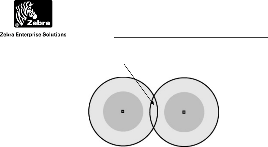
Figure 14 Overlapping Uncertainty Areas
Coverage Overlaps
When positioning WherePorts it is not always possible to prevent their fields from
overlapping. Overlapping the uncertainty areas of two WherePorts does not produce a
guaranteed capture area. It produces an area where a tag may be pinged by either one or
the other WherePorts or none.
When the fields of two WherePorts must be overlapped to cover a large area
(Figure 14) it is necessary to set the phases of the two WherePorts. Both WherePorts (or
more if more fields are overlapping) must also have the same ID number. If the phases
are not set, it may be impossible or difficult for a tag in the field to accurately report the
ID of the WherePort for the field it is in.
Field Overlap
User Guide
WherePort III User Guide D948 Rev B
©2010 Zebra Enterprise Solutions. WherePort and all product names and numbers are Zebra Enterprise Solutions trademarks. All oth
e
3.4 Phases
When two are more WherePorts are used to cover a large area they must be phased to
reduce the interference between the two fields. WherePorts mounted on the ceiling might
be set to 0º and on a wall 90º. Figure 15 shows the correct phase settings for four
orientations of the WherePort. The phases are set with reference to the orientation of the
master WherePort.
A WherePort set to 0º phase is defined as the master and all the other WherePorts
are then connected to it using the phase wire connections. Phased WherePorts must all
have the same ID.
Figure 15 Phase and WherePort Orientation
0º Master
90º
180 º
270 º
User Guide
WherePort III User Guide D948 Rev B
©2010 Zebra Enterprise Solutions. WherePort and all product names and numbers are Zebra Enterprise Solutions trademarks. All oth
e
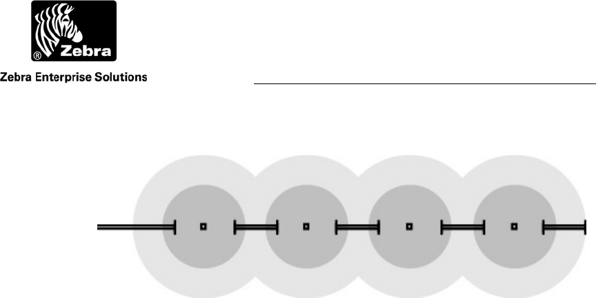
3.5 Sequencing
WherePorts that have been connected electronically can also operate in the sequence
mode. Sequenced WherePorts do not transmit at the same time. The first WherePort
sends its message and then shuts off its field while the next WherePort in the sequence
sends its message. The number of times each WherePort sends its message is set using
the CMCn command. The number of WherePorts in the chain is set using the CMWn
command. See Figure 16 through Figure 18.
The master WherePort LED in a group of sequenced WherePorts is green when
active. The slave WherePort LEDs are yellow when they are active. The LEDs are all off
when the WherePorts are not active.
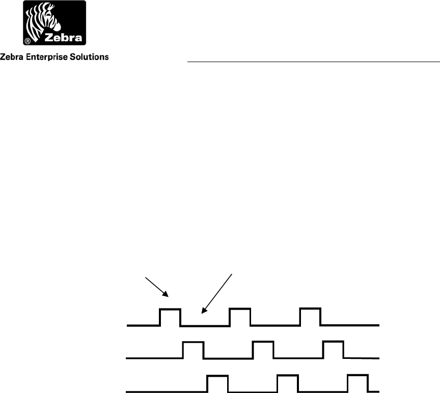
Figure 16 Mode 1
One WherePort is active at a time. A master and two slaves are
shown. WhereWand WPSeq Count (or RS232 CMWn) = 2.
Master WP #1
Slave WP #2
Slave WP #3
Active Inactive
User Guide
WherePort III User Guide D948 Rev B
©2010 Zebra Enterprise Solutions. WherePort and all product names and numbers are Zebra Enterprise Solutions trademarks. All oth
e
Figure 17 Mode 2
More than one WherePort may be active at a time. A master and
three slaves are shown. One and three are active while 2 and 4
are inactive. WhereWand WPSeq Count (or RS232 CMWn) = 1.
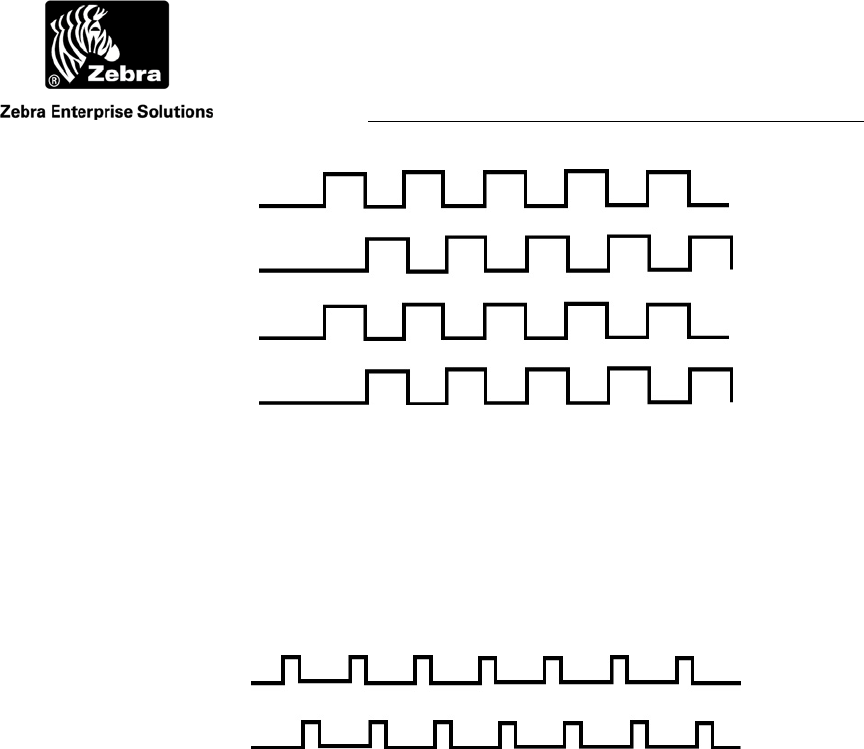
Figure 18 Mode 3
All WherePorts may be off part of the time. A master and one
slave are shown. One is active, then two, then both are inactive.
WhereWand WPSeq Count (or RS232 CMWn) = 2 or higher.
With sequencing, WherePorts that might have conflicting fields if they were on at the
same time, can be placed to indicate position or transitions. An example is narrow
parking lanes in a warehouse facility.
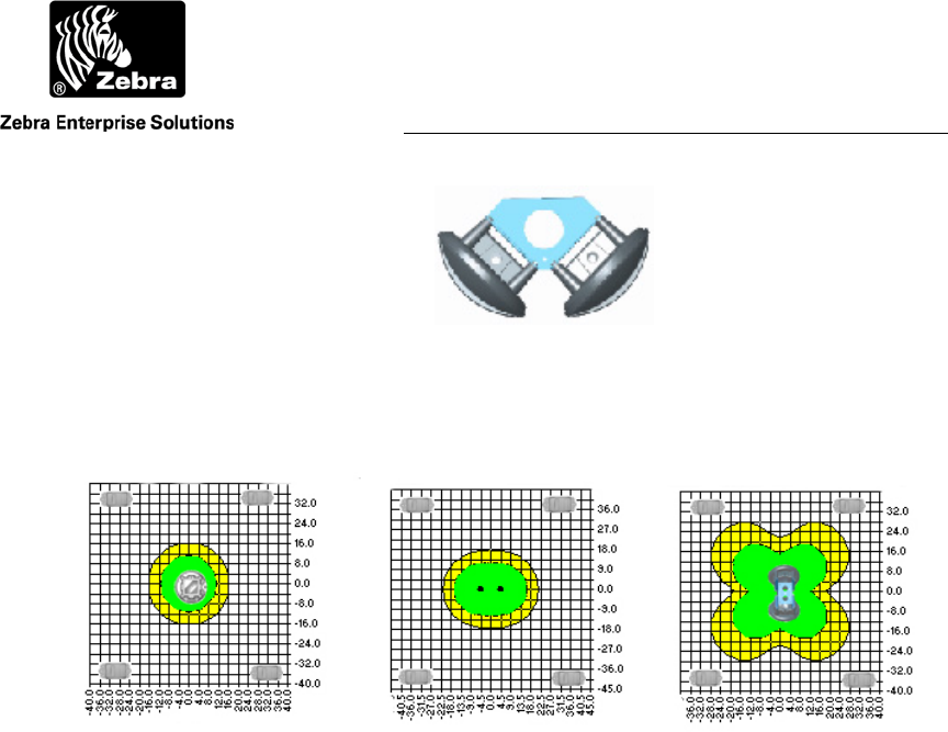
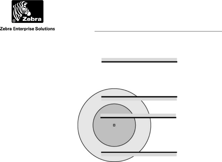
3.6 Dual WherePorts
The dual WherePort is a bracket with two WherePorts mounted to it, oriented 90º from
each other (Figure 19). They ensure a guaranteed capture range and eliminate the need
for multiple mounting sites. Typically the dual WherePort is used when the orientation of
the tag can not be fixed. They also simplify placement in locations that are larger than the
guaranteed capture range of a single WherePort (see Figure 20). Dual WherePorts are
always phased with one set as the master at 0º and the other at 90º.
Master WP #1
Slave WP #2
Slave WP #3
Slave WP #4
Master WP #1
Slave WP #2
User Guide
WherePort III User Guide D948 Rev B
©2010 Zebra Enterprise Solutions. WherePort and all product names and numbers are Zebra Enterprise Solutions trademarks. All oth
e
Figure 19 Dual Where Port
Figure 20 Coverage Pattern
A single (A), adjacent (B), and dual WherePort (C) field are
shown. The fields shown are for WherePorts at power level 8
and mounted at the same height as the WhereTag.
3.7 Interference
Steel objects and some devices can interfere with the WherePort field and change its
shape and range.
Some kinds of structures will affect the range of the WherePort. Mounting the
WherePort on the broad face of a steel I-beam reduces the coverage on the front and back
of the WherePort.
The field can also be extended or ducted by steel in windows, metal studs,
conduit, or duct work. This is most likely to occur when the WherePort is within one to
two feet of the steel and the tag is also close to the steel. This could lead to an unwanted
increase in the size of the field.
Magnetic interference can block communication between the WherePort and the
tag. The most common sources of magnetic interference are CRT monitors, electric
motors, vehicle RFID anti-theft ignition systems, and other WherePorts. A WherePort
may not ping a tag that is within one to two feet of an operational monitor or industrial
motor. The field strength meter can be used to check for interference.
A B C
User Guide
WherePort III User Guide D948 Rev B
©2010 Zebra Enterprise Solutions. WherePort and all product names and numbers are Zebra Enterprise Solutions trademarks. All oth
e
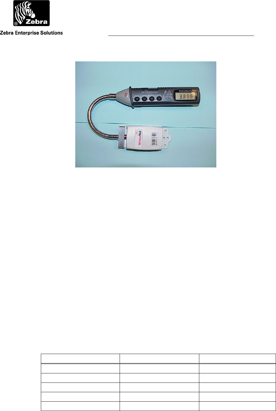
Figure 21 Magnetic Field Meter
3.8 The Field Meter
The field meter is a WhereTag connected to a voltage meter so that it can detect and
display the strength of the WherePort field (Figure 21). By walking around an installed
WherePort the strength of the signal throughout the area to be monitored can be
measured. The tag can be positioned to match its mounting position on the tracked asset.
Experimenting with the field meter can help to clarify the coverage area of the
WherePort.
After the installation of WherePorts at a facility, the field meter is used to test that
the field coverage is as it was planned to be. If gaps or problems with the coverage are
found they can be corrected before the facility is put into operation. See the Magnetic
Field Meter User’s Guide (P/N D0755).
3.9 The WherePort LED
On the top of the WherePort is an LED that indicates the status of the WherePort (see
Table 5).
Table 5 LED Status Indicator
Condition WherePorts LED Status
Power up reset All Red
Power = 0 All Red
Phased Master Green
Phased Slave Yellow
Sequenced Master, field on Green
User Guide
WherePort III User Guide D948 Rev B
©2010 Zebra Enterprise Solutions. WherePort and all product names and numbers are Zebra Enterprise Solutions trademarks. All oth
e
Sequenced Master, field off No color
Sequenced Slave, field on Yello
Sequenced Slave, field off No color
3.10 Capture Area Simulator
The capture area simulator calculates and maps the capture area for several different
WherePort and WhereTag orientations. The simulator is described in Chapter 6.
4 WHEREPORT IN THE FIELD
The basic principles of the WherePort must be translated into applications in the field.
Doors, corridors, rooms, parking lots do not necessarily conform to the requirements of
the WherePort field. In this chapter several common situations are discussed in order to
illustrate how the characteristics of the WherePort affect their positioning on a site.
Figure 22 WherePort Coverage
In the applications that follow the WherePort field will be illustrated as shown in Figure
22. The illustration shows only two dimensions of what is always a three dimensional
field. The field can be imagined as a series of waves that are further apart as they move
out from the coil. The overall shape is like an ellipsoid, an egg shaped object, extending
out in all directions from the WherePort.
In the examples that follow, the WherePort field is described. It must be
remembered that the capture area is what is important. The field is shown to simplify the
presentation.
Uncertaint
y
Covera
g
e
Guaranteed Coverage
WherePort

User Guide
WherePort III User Guide D948 Rev B
©2010 Zebra Enterprise Solutions. WherePort and all product names and numbers are Zebra Enterprise Solutions trademarks.
A
ll other trademarks are the property of their respective owners.
4.1 Zones
In some applications it is not necessary to be able to determine the precise position of an
asset. All that is needed is to know when the asset is in one or more key zones of the
facility. Fewer antennas are required to define zones.
While accuracy may not be essential, reliability will be. By placing one or more
WherePorts in a zone, the system can reliably determine that a tag asset has entered and
is still in a zone.
4.2 Area Coverage
There may, however, be many areas where different activities occur that must be
monitored. Well positioned WherePorts can define these areas of interest by pinging
tagged assets as they enter them. Examples are assembly stations in a factory, loading
docks, or different types of rooms in a hospital. One or more WherePorts mounted at the
station will ping a tag whenever the tag enters the area. If more than one port is placed in
a large area, they must all have the same ID.
The WherePort can be particularly important if the structure of the facility
obstructs the line of sight visibility to location sensors or location antennas. The garages
in a repair facility may have metal walls. Multiple sensors, likely four, would need to be
mounted around the bay to guarantee a signal that locates a vehicle in the bay.
When more areas are to be monitored, more issues must be considered in planning
the location of the WherePorts.
• What will the orientation of the tag be as it moves through the area?
• Will tags be pinged while they are moving past but not through the area?
• Are there sources of interference that may restrict the capture area?
• Will WherePorts be close enough to each other that their fields may
overlap?
4.3 Portals
An additional complexity may arise if the best way to monitor assets is to detect when an
asset enters or leaves the area through a door, gate, or similar portal. WherePorts
mounted at the portals of these areas will ping a tag, indicating that the tagged asset has
passed through and is not in the area.
User Guide
WherePort III User Guide D948 Rev B
©2010 Zebra Enterprise Solutions. WherePort and all product names and numbers are Zebra Enterprise Solutions trademarks.
A
ll other trademarks are the property of their respective owners.
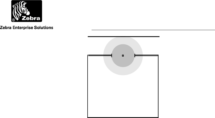
Figure 23 WherePort in a Doorway
To enter the room, an object must pass through the guaranteed
capture range of the WherePort.
The placement of a WherePort in the doorway might seem simple. Figure 23 shows this
installation. Any tagged asset passing through the doorway must pass through the
guaranteed capture range. However, an object passing down the corridor would also be
pinged by the WherePort. If the WherePort is mounted to the top of the doorway, it
might be below a space on the floor above that is part of the application as well. The
WherePort field might extend far enough into the second floor to ping a WhereTag
moving through a completely separate part of the facility.
The WherePort may need to be mounted inside the room to prevent pinging traffic
along the corridor. Its power level may need to reduced so that the range does not extend
beyond the actual portal. The placement of the tag on the asset may need to be adjusted,
perhaps by placing it closer to top of a vehicle, so that only the portal WherePort will
ping it.
When an area is monitored using portals, all portals must be covered. If a path
into the area is not covered by a WherePort, tagged assets may enter or leave through the
uncovered path.
Corridor
Functional Area
User Guide
WherePort III User Guide D948 Rev B
©2010 Zebra Enterprise Solutions. WherePort and all product names and numbers are Zebra Enterprise Solutions trademarks.
A
ll other trademarks are the property of their respective owners.
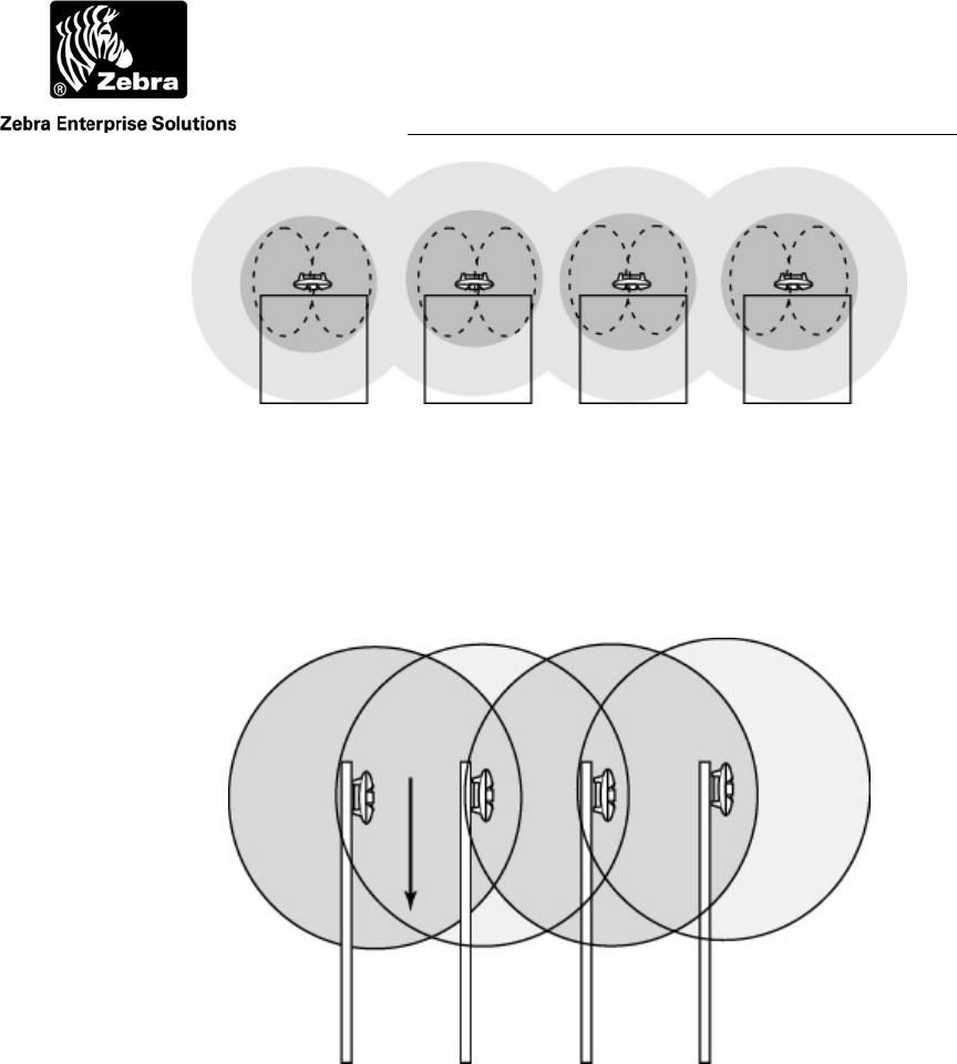
Figure 24 Loading Dock Doors
Spacing of loading dock doors makes it impossible to assign
unique WherePort IDs to each of the doors.
If, instead of a single door, a series of doors (for example on a loading dock) or bays are
too close together, the fields may overlap so that it is not possible to assign a unique
WherePort ID to each of the doors. Even if the doors are far enough apart so that the
fields do not overlap, the fields may cover so much of the adjacent area that false pings
are created by tags that are passing by and not arriving at the doors (see Figure 24).
Some of these issues might be solved by sequencing the WherePorts, which will
be covered later in this chapter.
User Guide
WherePort III User Guide D948 Rev B
©2010 Zebra Enterprise Solutions. WherePort and all product names and numbers are Zebra Enterprise Solutions trademarks.
A
ll other trademarks are the property of their respective owners.
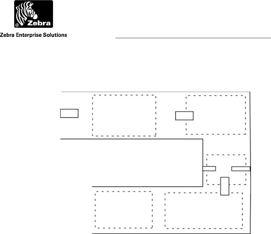
Figure 25 Multi-Floor Schematic
Shows a floor configuration so that the WherePort field extends
into the second floor.
4.4 Multi-Floor Installations
When activities are tracked on several floors, the vertical position of the WherePort and
the extent of its field must be carefully considered. If the field extends into the floor
above, a tag moving on the upper floor may be activated by the WherePort on the lower
floor. This will produce an incorrect location for the tag.
The height of the floor together with the utility space between floors must be
considered so that the WherePort is mounted at a height that prevents tags on the floor
above from being activated (Figure 25).
The WherePort power setting can be set so that the range is reduced. The tags
may also be mounted lower on the asset to permit lower placement of the WherePort.
4.5 Locked WherePorts
There may be areas on a site where once a tagged asset has entered it should not be
located using RTLS. Movement along an assembly line may be more accurately tracked
using only the WherePort signals. Where room coverage is needed the RTLS algorithm
could indicate that a tag is outside a room when it is not.
Floor 1
Drop Ceiling
Floor 2
Drop Ceiling
Utility Space

User Guide
WherePort III User Guide D948 Rev B
©2010 Zebra Enterprise Solutions. WherePort and all product names and numbers are Zebra Enterprise Solutions trademarks.
A
ll other trademarks are the property of their respective owners.
WherePorts are defined as locked using the software of the SystemBuilder. No
setting in the WherePort is needed. After a tag pings that it has detected a locked
WherePort the tag will be ignored until it is unlocked. It is unlocked by detecting an
unlocked WherePort.
Tag movement must be clearly understood to make sure that a tag that enters a
locked WherePort field will also enter an unlocked WherePort field. If a tag is
inadvertently locked by a WherePort it will be ignored by the system until it enters the
field of an unlocked WherePort.
Typically locked WherePorts are used to track tags into a relatively small and
confined space. While tags are in this space they will be ignored. Upon leaving the space
they will pass an unlocked WherePort and from then on be tracked normally.
4.6 Multiple WherePorts
Some locations require more than one WherePort to insure adequate coverage. Examples
include a large parking lot, a long corridor, a large number of loading dock doors, or a
large doorway.
If a space is large enough, separate WherePorts with separate IDs may be used.
Problems arise with areas that must be monitored uniquely that are larger than the
coverage area of single WherePort. In this case the possible mounting options must be
considered.
The placement of WherePorts with overlapping coverage requires attention to a
number of issues. The first is phasing. Whenever the coverage fields of two or more
WherePorts overlap, the phases of the WherePorts must be set. When WherePorts are
phased, one is always designated as the master with its phase set to 0 (see Figure 26) and
all phased WherePorts must be set to the same ID.
User Guide
WherePort III User Guide D948 Rev B
©2010 Zebra Enterprise Solutions. WherePort and all product names and numbers are Zebra Enterprise Solutions trademarks.
A
ll other trademarks are the property of their respective owners.
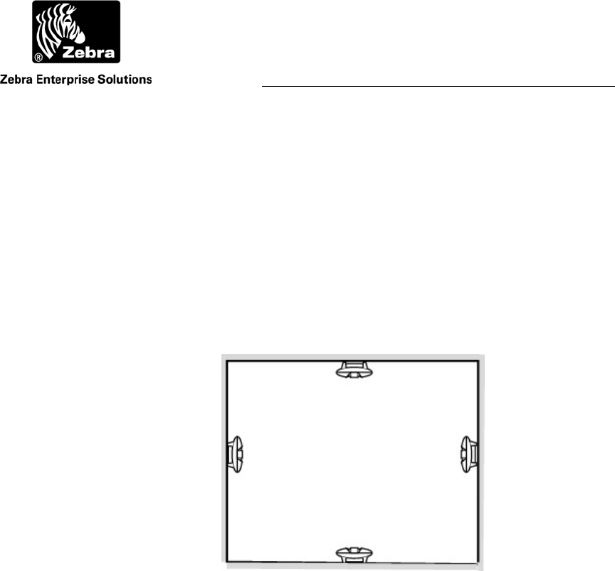
Figure 26 Phasing for Wall Mounted WherePorts
Viewed from the top.
Figure 26 shows a corridor or large space with WherePorts mounted on the different
walls to effectively cover the entire area. This means that the phase of each WherePort
must be set as indicated.
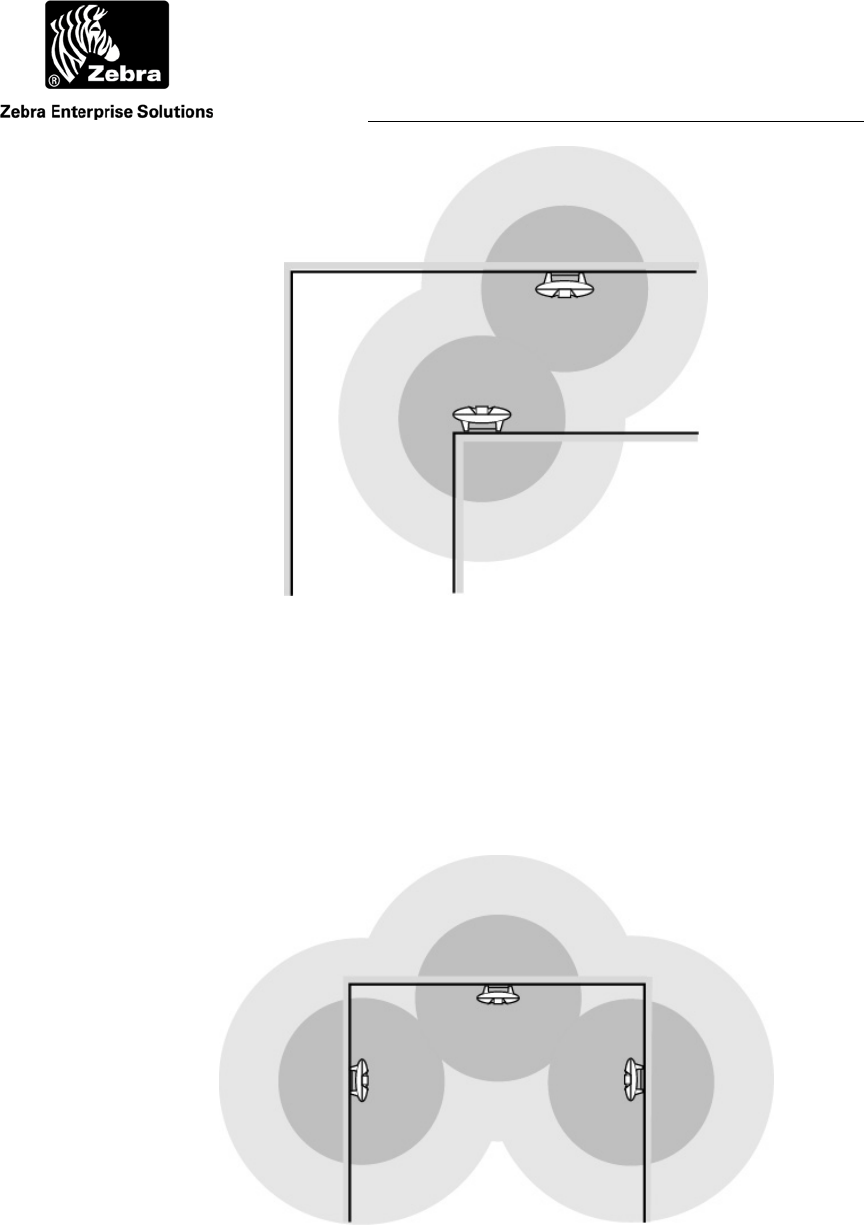
Figure 27 Phasing for Ceiling and Wall WherePorts
0º Master
180 º
0º Master
90 º
180 º
User Guide
WherePort III User Guide D948 Rev B
©2010 Zebra Enterprise Solutions. WherePort and all product names and numbers are Zebra Enterprise Solutions trademarks.
A
ll other trademarks are the property of their respective owners.
A large doorway may require three WherePorts to reliably detect the passage of a tagged
asset through it. In the example shown in Figure 27 coverage requires a WherePort on
each side of the doorway and on the ceiling. Again each WherePort must be phased
accordingly.
Figure 28 Loading Dock Door Options
Viewed from the side.
Loading dock doors are frequently too close together for each of them to be monitored by
a different WherePort. If unique identification of passage through a given door is
required, a more complex solution will be required.
Figure 28 and Figure 29 show two ways of solving the problem. The example in
Figure 28 uses a WherePort to cover two doors. Since these WherePorts are mounted in
different orientation on the walls, their phases must be set as well. Figure 29 shows a
WherePort mounted above each door. The phases for these ports can all be set to 0 but
they must still be phased together with one of the ports identified as the master.
The orientation of the tags will also affect the location of the WherePorts. If the
tag orientation is horizontal, then the top solution is best so that the WherePort field will
be maximized. If the tags are oriented vertically, then the lower solution, with the
WherePorts mounted over the doors, will be best.
0 º 0 º 180 º
User Guide
WherePort III User Guide D948 Rev B
©2010 Zebra Enterprise Solutions. WherePort and all product names and numbers are Zebra Enterprise Solutions trademarks.
A
ll other trademarks are the property of their respective owners.
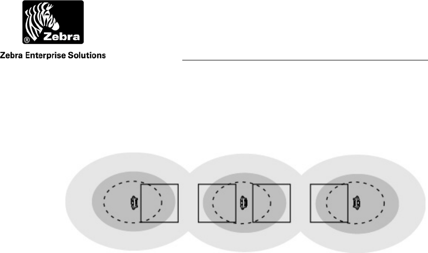
Figure 29 Over the Door WherePort Mounting
The dotted line ellipse shows the approximate shape of the
coverage area if the tag is oriented horizontally rather than
vertically.
Figure 30 Sequenced WherePorts on Parking Lanes
4.7 Sequenced WherePorts
Figure 30 shows the use of sequenced WherePorts to accurately identify which lane a
vehicle has entered. Sequenced WherePorts are turned on and off. WherePorts 1 and 3 are
on while 2 and 4 are off and then 2 and 4 are on while 1 and 3 are off. If a tag is pinged
by 1 and 2 it is in lane 1. If it is pinged by 3 and 2 it is in lane 2.
1 3
2 4

User Guide
WherePort III User Guide D948 Rev B
©2010 Zebra Enterprise Solutions. WherePort and all product names and numbers are Zebra Enterprise Solutions trademarks.
A
ll other trademarks are the property of their respective owners.
4.8 Summary
Each application will present a unique combination of the principles demonstrated by the
examples in this chapter and thus require different configurations to create a successful
application. In the next chapter, guidelines for planning and designing an application will
be discussed.
User Guide
WherePort III User Guide D948 Rev B
©2010 Zebra Enterprise Solutions. WherePort and all product names and numbers are Zebra Enterprise Solutions trademarks.
A
ll other trademarks are the property of their respective owners.
5 WORKING THROUGH AN APPLICATION
To effectively place WherePorts the site and the required information from the site must
be carefully studied. In this chapter a simple site will be presented and issues about
WherePort placement will be discussed and mounting locations for WherePorts found.
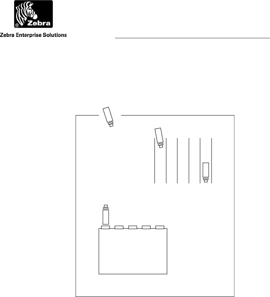
Figure 31 The Warehouse Site
5.1 Warehouse and Shipping Facility
Events or positions that need to be monitored in some way.
What must be tracked.
Trailers entering the yard
Trailers at the loading dock
Trailers in the waiting, parking area
Trailers leaving the yard

User Guide
WherePort III User Guide D948 Rev B
©2010 Zebra Enterprise Solutions. WherePort and all product names and numbers are Zebra Enterprise Solutions trademarks.
A
ll other trademarks are the property of their respective owners.
Issues affecting the placement of the WherePort.
Are there any obstacles or structures that will affect the field?
Where will the WhereTags be mounted?
Will their orientation be controlled while they are in a WherePort field?
The first and most important step in creating a successful WherePort application is to
define what information must be obtained from the WherePort. Is the passage of an asset
past a particular point important?
How does the use of WherePorts fit with the RTLS? Is it impossible to mount enough
sensors or do physical barriers make it impossible to get reliable location signals? Is the
RTLS unable to accurately track when an asset has reached a precise location? Both
aspects of the installation must be considered to make sure that the most accurate and
reliable information that is critical to operation is obtained.
Within a large area covered by RTLS more precise information about the location
of an asset may be needed. This can be done by installing a WherePort at this location.
User Guide
WherePort III User Guide D948 Rev B
©2010 Zebra Enterprise Solutions. WherePort and all product names and numbers are Zebra Enterprise Solutions trademarks.
A
ll other trademarks are the property of their respective owners.
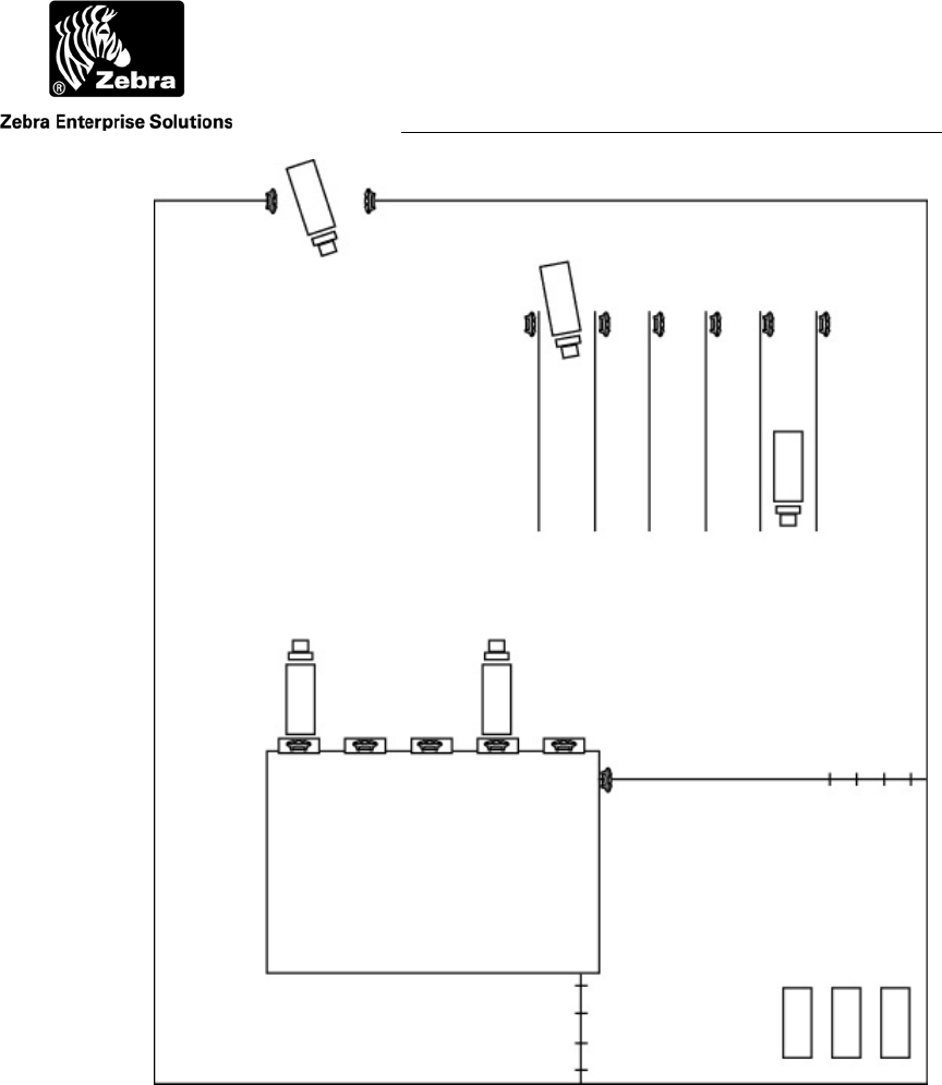
Figure 32 WherePorts Mounted on the Site
5.2 Positioning the WherePorts
What will the tags be mounted to and how will the objects move? Will the tag maintain
its orientation as it moves through the site or will it move? Will it move only in the
horizontal dimension or will it be set up on end and changed vertically as it moves? Will
the tag be mounted close to the floor or some distance above it? How much flexibility
will there be in the mounting of the tag? The orientation of the tag with respect to the
WherePort is one of the most important determinants of the coverage field.
What kinds of interference are on the site?
User Guide
WherePort III User Guide D948 Rev B
©2010 Zebra Enterprise Solutions. WherePort and all product names and numbers are Zebra Enterprise Solutions trademarks.
A
ll other trademarks are the property of their respective owners.
identifying where on the site this information must be gathered, and determining
Creating a map of the site.
User Guide
WherePort III User Guide D948 Rev B
©
2010 Zebra Enterprise Solutions. WherePort and all product names and numbers are Zebra Enterprise Solutions trademark
s
All other trademarks are the property of their respective owners.
6 USING THE SIMULATOR
The WherePort simulator (ZES p/n D0910) is a tool for exploring the best solutions for
WherePort placement and for better understanding the basic characteristics of WherePort
communication.
Because of the number of variables that affect the response of the tag to the
WherePort field, it is helpful to examine the response using the simulator. The number
and placement of WherePorts, the orientation of the tag while it is in the field, and the
distance of the WherePort from the tag all interact to determine this response.
6.1 Simulator Controls and Features
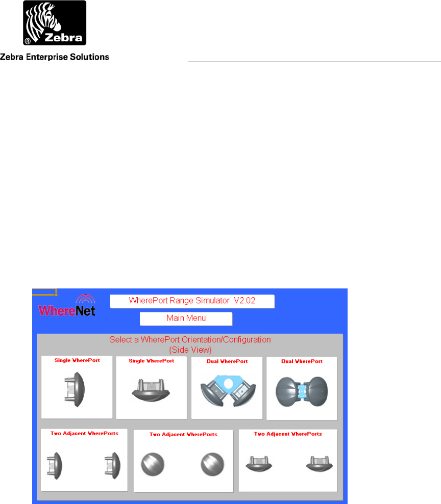
Figure 33 Starting the WherePort Simulator
Figure 33 shows the starting screen of the simulator. There are seven options for
WherePort placement:
Single WherePort Mounted vertically
Single WherePort Mounted horizontally
Dual WherePort Mounted horizontally
Dual WherePort Mounted Vertically
User Guide
WherePort III User Guide D948 Rev B
©2010 Zebra Enterprise Solutions. WherePort and all product names and numbers are Zebra Enterprise Solutions trademarks.
A
ll other trademarks are the property of their respective owners.
Two Adjacent WherePorts Mounted vertically, facing sideways
Two Adjacent WherePorts Mounted vertically, facing forward
Two Adjacent WherePorts Mounted horizontally
The magnetic field extends in all directions from the WherePort. Its position does,
however, affect the direction of the field and therefore its relation to the position of the
tag. It is the direction of the field that is important when reviewing the different
orientations of the WherePort.
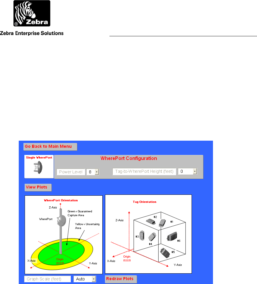
Figure 34 Configuration Screen
6.2 WherePort Configuration
The WherePort position to be simulated is configured on the WherePort configuration
screen (Figure 34). There are two parameters that must be set:
Power Level Select a power lever from 1 to 8. The highest power
level is 8.
Tag to WherePort Height (feet) The relationship between the height of the
WherePort position and the WhereTag position (0 to
20 feet).
User Guide
WherePort III User Guide D948 Rev B
©2010 Zebra Enterprise Solutions. WherePort and all product names and numbers are Zebra Enterprise Solutions trademarks.
A
ll other trademarks are the property of their respective owners.
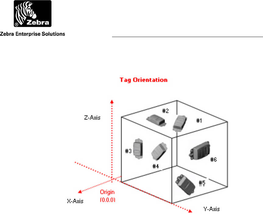
Figure 35 Tag Orientations for the Graphs
The graphs are calculated based on the tags maintaining the
same orientation while it moves. Its orientation to the field will
therefore change.
For each WherePort position, graphs are drawn for six different WhereTag orientations.
These orientations and the number designations of each are shown in Figure 35 The tag
orientation is with reference to the position of the WherePort.
There are also options for controlling the presentations of the graphs. The scale sets the
dimensions of the graph. A five foot scale displays the capture area for five feet in each
direction. A sample graph is shown in Figure 36.
User Guide
WherePort III User Guide D948 Rev B
©2010 Zebra Enterprise Solutions. WherePort and all product names and numbers are Zebra Enterprise Solutions trademarks.
A
ll other trademarks are the property of their respective owners.
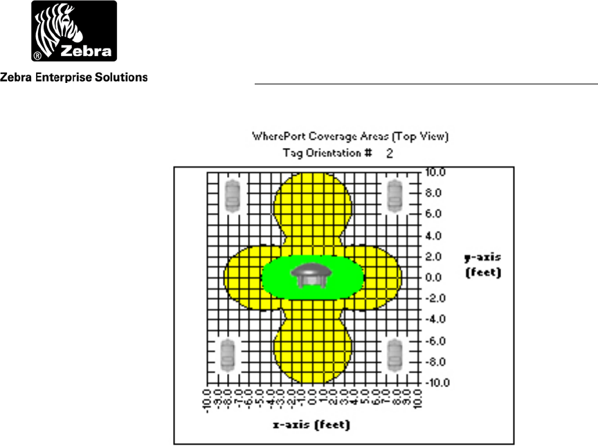
Figure 36 Sample Graph
The graph shows the guaranteed capture area in green and the
uncertainty area in yellow for a single WherePort, mounted
horizontally, with a power level of 4, and a tag to WherePort
height of 4 feet for a tag with orientation 2. The scale is 10.
User Guide
WherePort III User Guide D948 Rev B
©2010 Zebra Enterprise Solutions. WherePort and all product names and numbers are Zebra Enterprise Solutions trademarks.
A
ll other trademarks are the property of their respective owners.
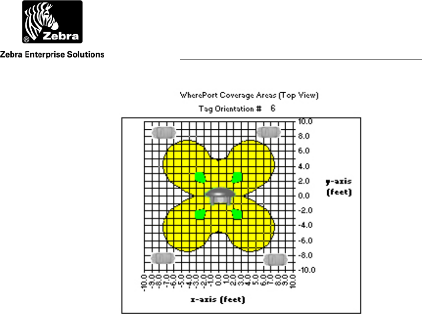
Figure 37 Sample Graph
Shows the same configuration as Figure 4 except the tag is in
the 6 orientation.
6.3 Sample Graphs
The importance and usefulness of the simulator can be shown by looking at two graphs
showing two different tag orientations while all other options are identical. Figure 36,
with orientation 2, shows a guaranteed capture area that is approximately ten feet long
and four feet wide. Figure 37, with orientation 6, has four very small guaranteed capture
areas that are not contiguous. These settings would likely not be effective for any
application.
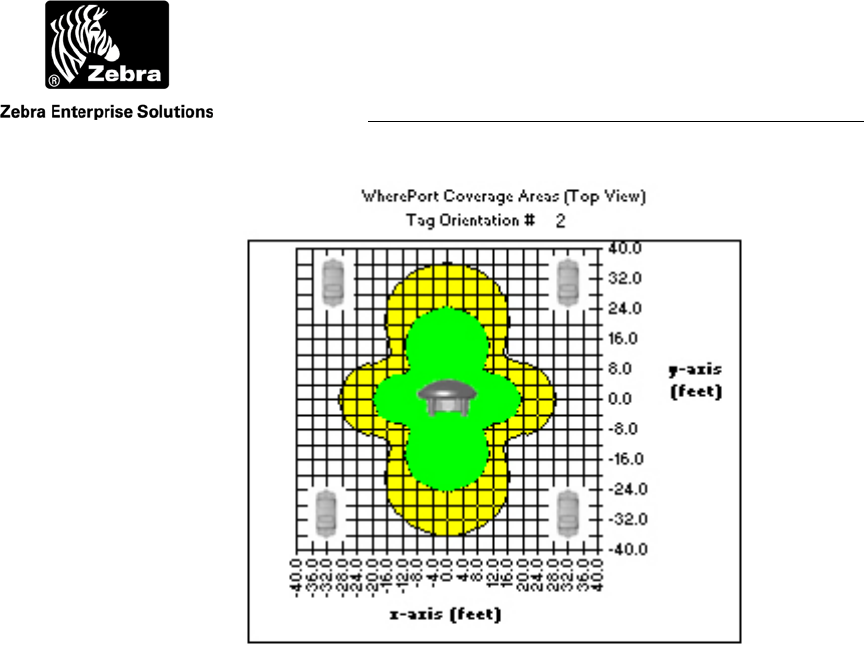
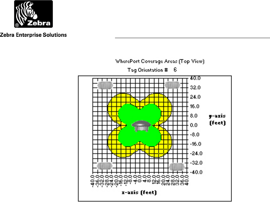
Figure 38 and Figure 39 use the same settings as Figure 36 and Figure 37 except
the power setting is 8 instead of 4.
User Guide
WherePort III User Guide D948 Rev B
©2010 Zebra Enterprise Solutions. WherePort and all product names and numbers are Zebra Enterprise Solutions trademarks.
A
ll other trademarks are the property of their respective owners.
Figure 38 Power Level Comparison Tag Orientation 2
User Guide
WherePort III User Guide D948 Rev B
©2010 Zebra Enterprise Solutions. WherePort and all product names and numbers are Zebra Enterprise Solutions trademarks.
A
ll other trademarks are the property of their respective owners.
Figure 39 Power Level Comparison Tag Orientation 6
User Guide
WherePort III User Guide D948 Rev B
©2010 Zebra Enterprise Solutions. WherePort and all product names and numbers are Zebra Enterprise Solutions trademarks.
A
ll other trademarks are the property of their respective owners.
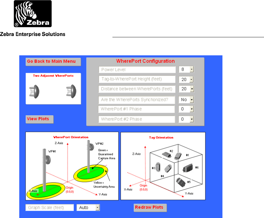
Figure 40 Adjacent WherePort Configuration
6.4 Adjacent WherePorts
Adjacent WherePorts require that some additional variables be set:
Power Level Select a power lever from 1 to 8. The highest power
level is 8.
Tag to WherePort Height Set from 0 to 20 feet.
Distance between WherePorts (feet) 0 to 50 feet in five foot increments.
Are the WherePorts Synchronized Yes or no (wired together).
WherePort #1 Phase 0, 90, 180, or 270.
WherePort #2 Phase 0, 90, 180, or 270.

User Guide
WherePort III User Guide
©2010 Zebra Enterprise Solutions. WherePort and all product names and numbers are Zebra Enterprise Solutions trademarks.
A
ll other trademarks are the property of their respective owners.
7 COMMAND SUMMARY
This section describes the commands used to configure the WherePort.
All commands and responses are ASCII character strings.
ACK responses are the three character string ‘ACK’ and not the 0x06 non-
printable character. Similarly, NAK responses are the three character string ‘NAK’ and
not the 0x15 non-printable character.
All numbers (represented by ‘n’ in command list) sent are the ASCII
representation of the value. For example, the number 14 is sent as the two ASCII
character string ‘14’ and not the single byte 0x0E. The number 7 is sent as the single
ASCII character ‘7’ and not the single byte 0x07.
7.1 Initial Power Up
When theWherePort is initially powered up, it will transmit the following string.
{CR}{LF}
WhereNet{CR}{LF}
WherePort vx.xx <CR><LF> (where x.xx is the firmware version)
7.2 Passwords
Every command must start with a four character password followed by a colon. For
example, if the passwore is 1234 the query command would be entered as follows:
1234:VER?<CR><LF>
The WherePort will respond with NAK to any command that does not start with the
correct password.
The WherePort ignores space characters, carriage return characters, and the line feed
character because it signals the end of a command. These three characters (0x0D, 0x0A,
0x20) may not be used in passwords. All other byte values are legal.
The password is set to the default value of 1234. The only command that does not require
the password is the HWT n command. The HWT n command sets and queries the
password. To access the password, the host must send the following three commands in
order. Any other command, or any change to the sequence will reset the access flags. The
sequence of commands is:
HWT 3 Set flag 1 of 3 only if all 3 flags are cleared.
HWT 4 Set flag 2 of 3 only if flag 1 is set and 2 and 3 are clear.
HWT 5 Set flag 3 of 3 only if flags 1 and 2 are set and 3 is clear.
HWT 6 Set password to 1234 only if all 3 access flags are set.

User Guide
WherePort III User Guide
©2010 Zebra Enterprise Solutions. WherePort and all product names and numbers are Zebra Enterprise Solutions trademarks.
A
ll other trademarks are the property of their respective owners.
The password can be set using the ****:XPW **** command. Changes to the password
will take effect immediately. The changes affect only the current session unless the host
sends the WherePort an execute command (****:EXE). Only after receiving an execute
command will the new password be written into flash memory and read on power up.
Without the execute command, the password will return to its previous value if the
WherePort is powered down.
7.3 Command Execution
The following commands require the execute command (****:EXE) before they will be
saved in flash memory and sent to the magnetic field generator:
MSG, PWR, PHS, WID, TID, RSP, CNT, INT, TRG, DAT, CMW, CMC, XPW
A query command will return the newly entered values, even though the execute
command has not been sent. The WherePort will not be operating under these values until
the execute command is sent.
7.4 Tag Responses to Commands
Unless noted otherwise, all commands will produce one of the following responses by the
WhereTag
ACK message OK
NAK message not recognized or bad format
NAK2 message parameter out of range
There are two other possible acknowledgments that are used primarily by data
commands. Their use will be noted in the command summary.
NAK3 The tag is busy and will not blink data
BSY…ACK The tag is busy with a WherePort blink. The command
will be responded to when the tag completes the
WherePort blink and is not busy, at which time a ACK
response will be sent.
SSS n Response to a query where SSS is the command and n
is the parameter.
All tag response strings consist of a carriage return / line feed, the actual response string,
another carriage return / line feed, and are followed by the > prompt character.
{CR}{LF} ACK{CR}{LF}>

User Guide
WherePort III User Guide
©2010 Zebra Enterprise Solutions. WherePort and all product names and numbers are Zebra Enterprise Solutions trademarks.
A
ll other trademarks are the property of their respective owners.
7.5 Commands
7.5.1 Message Length
Set the length, in bits, of the WherePort message. There are six possible values.
n Value
1 10 bit
2 28 bit
3 44 bit
4 144 bit
5 144 bit with payload CRC1
6 144 bit with payload CRC2
Example
MSG 1<cr>
Sets the message length to 10 bits.
Considerations
Message length affects the dwell time when using sequenced WherePorts.
7.5.2 Power
Set power level, from 0 to 8. When set to 0 the WherePort power is off.
PWR n<cr>
Increasing the power level increases the range.
Example
PWR 8<cr>
Sets the power level to 8.
Considerations
Lower power levels are used to make sure the capture area of the WherePort is restricted
to the zone or area to be monitored.
7.5.3 Phase
Set the phase.
PHS n<cr>
Valid range for n is 0 through 3 where 0 equals 0º, 1-90 º, 2-180 º, and 3-270 º.

User Guide
WherePort III User Guide
©2010 Zebra Enterprise Solutions. WherePort and all product names and numbers are Zebra Enterprise Solutions trademarks.
A
ll other trademarks are the property of their respective owners.
Example
PHS 2<cr>
Sets the phase to 2.
Considerations
When WherePort fields overlap, the phase of each WherePort must be set to match to
placement of the ports.
7.5.4 WherePort ID
Sets the WherePort Id. The valid range is 0 to 32,767.
WID n<cr>
Example
WID 4<cr>
Sets the WID to 4.
Considerations
WherePort IDs 0 through 255 are used for an alternate blink mode. When a WhereTag is
pinged by a WherePort with an ID less than or equal to 255 the tag is converted to the
alternate blink mode.
CAUTION Do not use the alternate blink mode without consulting the Zebra
Enterprise Solutions technical staff.
7.5.5 Tag Id
Set the tag ID (for 144 bit messages only). The valid range is 0 to 4,294,967,295.
TID n<cr>
Example
TID 4<cr>
Sets the tag id to 4.
Considerations
The tag ID is only set using a 144 bit message.
7.5.6 Response
Sets the tag WherePort response blink type (applies only to 27 bit and 44 bit messages)
RSP n<cr>
1 72 bit
2 144 bit

User Guide
WherePort III User Guide
©2010 Zebra Enterprise Solutions. WherePort and all product names and numbers are Zebra Enterprise Solutions trademarks.
A
ll other trademarks are the property of their respective owners.
Example
RSP 1<cr>
Set the response blink type to 72 bits.
7.5.7 Count
Set the WherePort response blink count (44 bit message only).
CNT n<cr>
Valid range for n is 0 through 15.
Example
CNT 4<cr>
Sets the blink count to 4.
7.5.8 Interval
Set the WherePort response blink interval (44 bit message only ) where n is 0 to 7.
INT n<cr>
7.5.9 Trigger
Set the re-trigger response (44 bit message only).
TRG n<cr>
Where n is a value 0 through 15.
Example
TRG 4<cr>
Sets the re-trigger response to .
7.5.10 Data
Set the 96 bit data payload (144 bit message only).
DAT [string]<cr>
String of 24 ASCII-HEX characters; set the 96 bit data payload (144 bit message only).
String of 22 ASCII-HEX characters: set the 96 bit data payload, payload CRC
automatically calculated (144 bit message only).
Example
DAT string<cr>

User Guide
WherePort III User Guide
©2010 Zebra Enterprise Solutions. WherePort and all product names and numbers are Zebra Enterprise Solutions trademarks.
A
ll other trademarks are the property of their respective owners.
A string of 24 ASCII-HEX characters to set the 96-bit data payload of the WherePort.
7.5.11 EXE
EXE n<cr>
Send message to magnetic field generator and the flash memory.
7.5.12 Sequence Mode
Set number of WherePort in the chain for sequencing mode.
CMW n<cr>
Where n is a value of 1 through 15. A value of 0 disables sequence mode. A value of 1
means that there is a master and 1 slave.
Example
CMW 2<cr>
Sets the number of WherePorts in the chain to 3, one master and 2 slaves.
7.5.13 Sequence Mode Message Number
CMC n<cr>
N is a value from 0 to 15. Sets the number of messages to send for each WherePort in
sequence mode. 0 disables sequencing mode.
The dwell time (how long it takes to send the programmed number of messages)
increases as the number of messages increases. Table 1 lists the dwell times for the
available combinations of message lengths and message numbers. The types are listed in
the left column. The number of messages are listed in the body of the table. The dwell
time is shown in the header column.
Table 1 Dwell Time (in seconds)
Message
Type 0.2 0.5 1.0 2.0 3.0 4.0 5.0 10 15 20
1 25 64 128 255
2 12 30 60 120 181 255
3 8 20 41 82 123 164 205
4 3 7 14 27 41 55 68 137 205 255
5 3 7 14 27 41 55 68 137 205 255
6 3 7 14 27 41 55 68 137 205 255

User Guide
WherePort III User Guide
©2010 Zebra Enterprise Solutions. WherePort and all product names and numbers are Zebra Enterprise Solutions trademarks.
A
ll other trademarks are the property of their respective owners.
7.5.14 Version
Set the software version number.
VER m.nn<cr>
Where m is the major version and nn is the minor version.
Example
VER 2.01<cr>
Sets the WherePort software version number to 2.01.
7.5.15 XPW
Set the password to the four character ssss.
XPW ssss<cr>
7.5.16 HWT (1)
Used to test the ISP port pins and set the WherePort password access flags.
HWT n<cr>
Where n is a value of 1 through 6. A value of 6 sets the default password.
Example
HWT 2<cr>
7.5.17 Loader
LDR n/a WherePort Loader vm.nn
Enter loader mode to allow firmware update. Will time out after 80 seconds if there
is no transfer. Transfer format is xmodem 128 byte.
7.5.18 GQ
There are five different GQ commands. A number of arguments are possible for several
of these commands. The commands govern the operation of the WherePort when the
mode is changed by the system in response to a particular tag.
GQ1
Set message length = 10 bit
Execute immediately
GQ1 n
Set WPID = n, where 0 ≤ n ≤ 7

User Guide
WherePort III User Guide
©2010 Zebra Enterprise Solutions. WherePort and all product names and numbers are Zebra Enterprise Solutions trademarks.
A
ll other trademarks are the property of their respective owners.
Set message length = 10 bit
Execute immediately
GQ2
Set message length = 28 bit
Execute immediately
GQ2 n
Set WPID = n, where 0 ≤ n ≤ 32,767
Set message length = 10 bit
Execute immediately
GQ3 n,m,p,q
n = 0x0-0x7FFF
m = 0x0-0xF
p = 0x1-0x7
q = 0x0-0xF
Arguments are in upper case ASCII-Hex format
Set message length = 44 bit
Set WPID = n
Set CNT = m
Set INT = p
Set TRG = q
Execute immediately
GQ4
Set message length = 144 bit
Execute immediately
GQ4 n
Set Tag ID n = 0 to 7FFF
Argument is in ASCII-Hex format
Set message length = 144 bit (CRC)
Execute immediately

User Guide
WherePort III User Guide
©2010 Zebra Enterprise Solutions. WherePort and all product names and numbers are Zebra Enterprise Solutions trademarks.
A
ll other trademarks are the property of their respective owners.
GQ4 s
Set message length = 144 bit (CRC)
Set data string = s (22 or 24 chars)
String is in ASCII-Hex format
Execute immediately
GQ4 n,s
n = 0 to 7FFF
s = string
Set message length = 144 bit (CRC)
Set Tag ID = n
Set data string = s (22 or 24 chars)
Execute immediately
GQ5 n
N = 0 to 7FFF
Set message length = 144 bit (CRC)
Set Tag ID = n
Execute immediately
GQ5 s
Set message length = 144 bit (CRC)
Set data string = s (22 or 24 chars)
Execute immediately
GQ5 n,s
n = 0 to 7FFF
s = string
Set message length = 144 bit (CRC)
Set Tag ID = n
Set data string = s (22 or 24 chars)
Execute immediately
GQ6 n
0 to 7FFF
Set message length = 144 bit (CRC)

User Guide
WherePort III User Guide
©2010 Zebra Enterprise Solutions. WherePort and all product names and numbers are Zebra Enterprise Solutions trademarks.
A
ll other trademarks are the property of their respective owners.
Set Tag ID = n
Execute immediately
GQ6 s
Set message length = 144 bit (CRC)
Set data string = s (22 or 24 chars)
Execute immediately
GQ6 n,s
n = 0 to 7FFF
s = string
Set message length = 144 bit (CRC)
Set Tag ID = n
Set data string = s (22 or 24 chars)
Execute immediately
User Guide
WherePort III User Guide
©2010 Zebra Enterprise Solutions. WherePort and all product names and numbers are Zebra Enterprise Solutions trademarks.
A
ll other trademarks are the property of their respective owners.
8 INSTALLATION
The lists of required parts, both supplied with the WherePort (Figure 41) and required
but not supplied, and the instructions for mounting WherePorts in typical locations
follow.
Caution - Use of Zebra external power supply is limited to indoor use
and a max 40° C environment. Outdoor installations will require
installation of a limited power source by the installer.
Warning - Electrical Shock: No operator serviceable parts inside.
Refer servicing to qualified personnel. To prevent electrical shock, do not
remove covers.
Caution - The WherePort III must be installed by a qualified service
technician.
Caution – Sync cable use is limited to indoor to indoor installation or
outdoor to outdoor installation. Sync cables must not be installed between
indoor and outdoor installations.
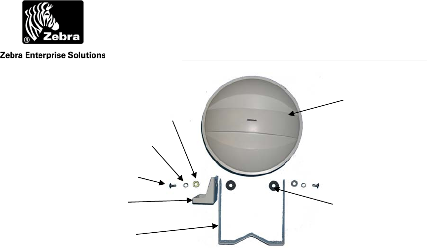
8.1 WherePort Parts
1. 1/4 x ½ in (12mm) screw (2)
2. Lock washer 2)
3. Flat washer (2)
4. Rubber bushing (2)
5. Bracket (1)
6. WherePort (1)
7. Tag Bracket (1)
8. Power/Sync Cable (1)
User Guide
WherePort III User Guide
©2010 Zebra Enterprise Solutions. WherePort and all product names and numbers are Zebra Enterprise Solutions trademarks.
A
ll other trademarks are the property of their respective owners.
Figure 41 Installation Kit
The power/synchronization cable is not shown.
8.2 Also Required (not included)
1. Power supply, North American PS-025-00
2. Power supply, International PS-030-00
3. Power supply, vehicle 12 V, PS-200-00
4. Interconnect cabling Belden p/n 9156
5. WhereWand Programmer WND-2010 or WND-2200
6. Cable Assembly, WhereWand I to WherePort III CBL-300-00
7. Cable Assembly, WhereWand II to WherePort III CBL-320-00
½ inch Screw (2x)
Lock Washer (2x)
Flat Washer (2x)
Tag Bracket
Bracket
WherePort
Rubber Bushing (2x)
User Guide
WherePort III User Guide
©2010 Zebra Enterprise Solutions. WherePort and all product names and numbers are Zebra Enterprise Solutions trademarks.
A
ll other trademarks are the property of their respective owners.
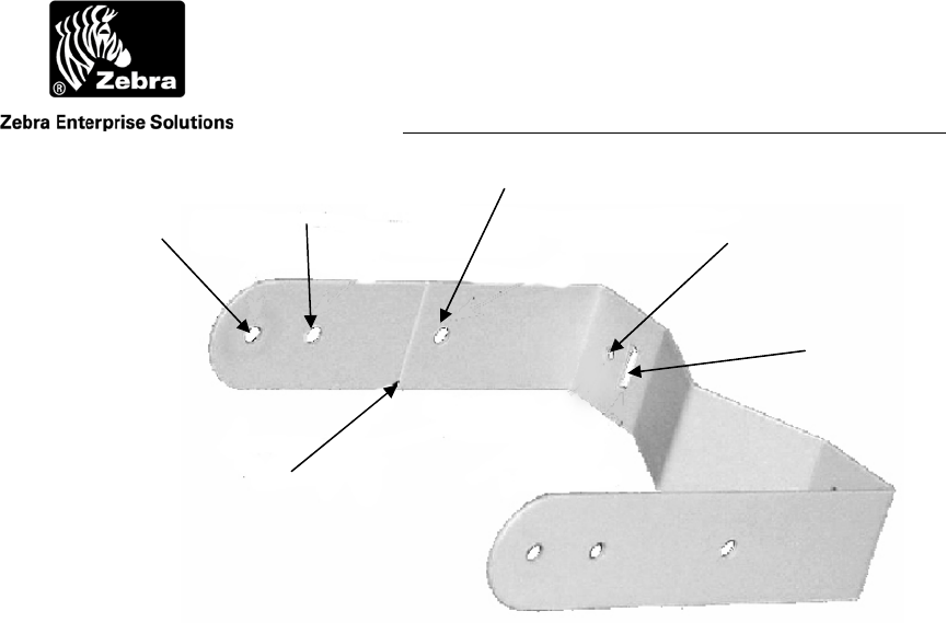
Figure 42 Mounting Bracket
8.3 Installation Procedure
Step 1 Determine mounting location based on Zebra Enterprise Solutions site design
worksheet.
Step 2 Determine orientation of WherePort compared to mounting surface.
Choose bracket hole depending on pole mount, side mount, or rear mount.
Break bracket tab for rear mount (Figure 42). Mount bracket to wall using #
8 (4 mm) screws (not supplied) or ½ in (12 mm) straps for pole mount.
Step 3 Mount WherePort to bracket using supplied hardware.
For Angled
Mount
For Side
Mount
For Rear
Mount
Break Off Tab for
Rear Mount
Hole for Wall
Mount
Slots for Pole
Mount
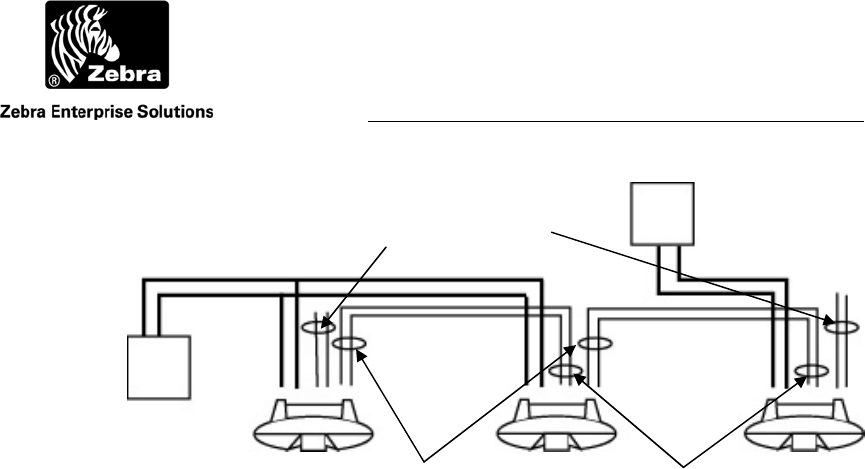
User Guide
WherePort III User Guide
©2010 Zebra Enterprise Solutions. WherePort and all product names and numbers are Zebra Enterprise Solutions trademarks.
A
ll other trademarks are the property of their respective owners.
Figure 43 Wiring Schematic for Synchronized WherePorts
Since there are more the two WherePorts there are two 24 volt
AC power supplies.
Step 4 Connect wiring: white & black pair to power; red & blue pair to following
WherePort; green & orange pair to previous WherePort (Figure 43).
Note: Do not connect more than two WherePorts to an AC transformer.
Step 5 Use WhereWand and programming cable assembly to set the ID, power, and
phase per the site design worksheet and WhereWand User Guide D0071. If
desired, the WherePort can be programmed prior to installation.
24 VAC
Transformer
24 VAC
Transformer
Output Sync
Red & Black Input Sync.
Green & Black
Unused, Do not
Terminate
Power
Black & White

User Guide
WherePort III User Guide D948 Rev B
©2010 Zebra Enterprise Solutions. WherePort and all product names and numbers are Zebra Enterprise Solutions trademarks.
A
ll other trademarks are the property of their respective owners.
A
Glossary
blink A signal sent by a WhereTag to the RTLS system. A blink may
contain 1 to 8 sub-blinks.
coverage area The area in which a WhereTag will be pinged by a WherePort
signal.
dual WherePort Two WherePorts on a bracket, oriented at 90 degrees to each other.
guaranteed WP capture area The part of the WherePort field where a tag will be
pinged.
WP health tag A WhereTag mounted to a WherePort to indicate if the WherePort
is operating correctly.
WP field The magnetic field produced by the WherePort. It is not the same
as the coverage area.
guaranteed WP release area The point beyond which it is certain that a tag will
not be pinged.
locked A tag may be locked by a WherePort. A locked tag is invisible to
the RTLS system. Must be paired with a WherePort that unlocks
the tag.
master In a group of phased WherePorts, one must be set as the master.
The phase setting for the master is 0.
orientation Magnetic coils have an orientation. The relationship between the
orientation of the pick up coil in the WhereTag and the transmit
coil in the WherePort affects the range of the WherePort.
phase WherePort setting required when uncertainty areas of coverage
overlap between two or more WherePorts. The possible phase
settings are 0, 90, 180, and 270.
ping What a WherePort does to a WhereTag when the tag is in the field.
sequence WherePorts linked together which transmit at intervals set by the
master WherePort in the sequence.

User Guide
WherePort III User Guide D948 Rev B
©2010 Zebra Enterprise Solutions. WherePort and all product names and numbers are Zebra Enterprise Solutions trademarks.
A
ll other trademarks are the property of their respective owners.
simulator A software package for experimenting with coverage areas.
slave All WherePorts other than the maser in a group of sequenced or
phased WherePorts.
uncertainty area The part of the WherePort field where a tag may be pinged but
where it is also possible that it will not be pinged.
WherePort ID A number from 0 to 32,000 that identifies each WherePort to the
system.
WherePort III User Guide
©2010 Zebra Enterprise Solutions. WherePort and all product names and numbers are Zebra Enterprise Solutions trademarks.
A
ll other trademarks are the property of their respective owners.
B
Index
alternate blink mode, 11
dual WherePort, 18
field meter, 20
guaranteed capture, 14
guaranteed release, 14
health tag, 6
interference, 19
LED, 20
magnetic field, 12
modes, 8
mounting bracket, 6
overlapping fields, 16
phase, 17
phased
master, 27
power level, 15
sequenced, 29
simulator, 21
specifications, 5
uncertainty, 14
WherePort ID, 4
WhereTag coil orientation, 8
WhereTag response modes, 8