Zebra Technologies WPT-3200 Proximity Communications Device User Manual D0116 rev A sec 5 WherePort Placement 020921

Zebra Technologies Corporation Proximity Communications Device D0116 rev A sec 5 WherePort Placement 020921

Contents

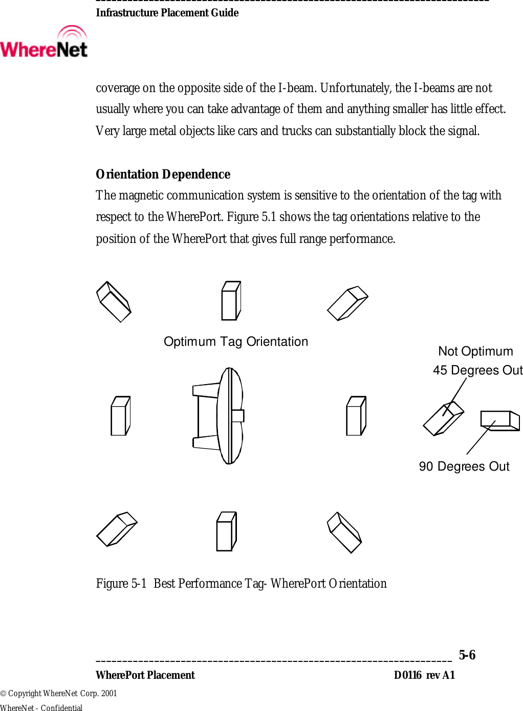
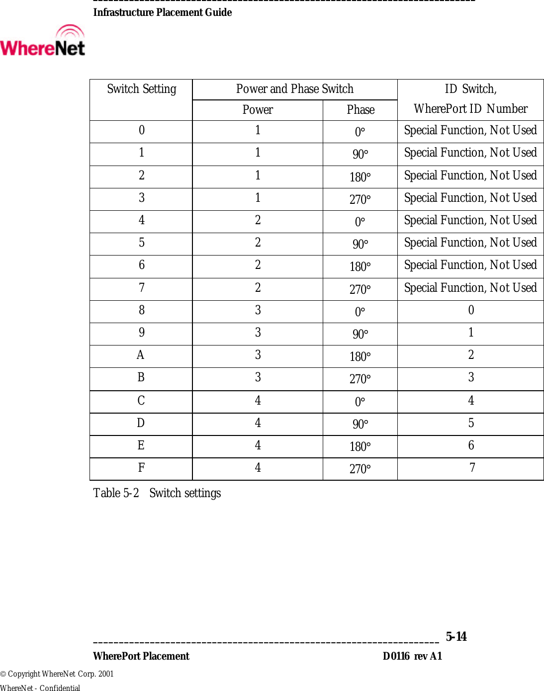
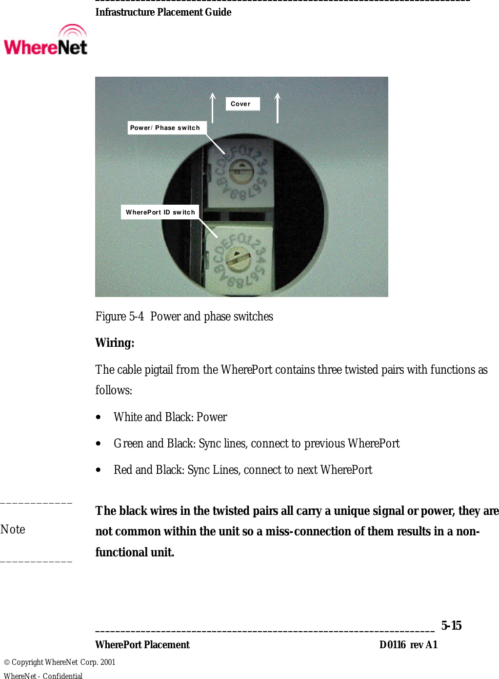
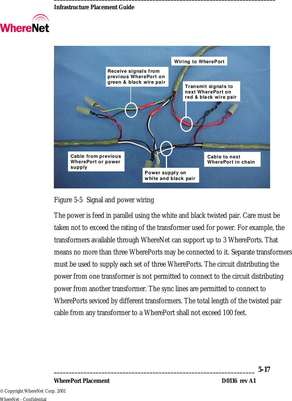
WherePort Users Manual Rev A1

 __________________________________________________________________________  Infrastructure Placement Guide       ___________________________________________________________________  5-1  WherePort Placement D0116  rev A1  Copyright WhereNet Corp. 2001   WhereNet - Confidential WHEREPORT PLACEMENT
 __________________________________________________________________________  Infrastructure Placement Guide       ___________________________________________________________________  5-2  WherePort Placement D0116  rev A1  Copyright WhereNet Corp. 2001   WhereNet - Confidential Table of Contents Page 5  WHEREPORT PLACEMENT  4 5.1  OVERVIEW  4 5.2  MAGNETIC COMMUNICATION  5 5.3  APPLICATION STRATEGIES  8 5.4  WHEREPORT INSTALLATION  13  Table of Figures Page FIGURE 5-1 BEST PERFORMANCE TAG- WHEREPORT ORIENTATION  6 FIGURE 5-2 WHEREPORT COVERAGE AREA  10 FIGURE 5-3 TYPICAL WHEREPORT PHASE SETTINGS  11 FIGURE 5-4 POWER AND PHASE SWITCHES  15 FIGURE 5-5 SIGNAL AND POWER WIRING  17  Table of Tables Page TABLE 5-1 TYPICAL WHEREPORT RANGE  12 TABLE 5-2 SWITCH SETTINGS  14
 __________________________________________________________________________  Infrastructure Placement Guide       ___________________________________________________________________  5-3  WherePort Placement D0116  rev A1  Copyright WhereNet Corp. 2001   WhereNet - Confidential  NOTICE This device complies with part 15 of the FCC rules. Operation is subject to the following conditions: (1) This device may not cause harmful interference, and (2) this device must accept any interference, which may cause undesired operation. Changes or modifications not expressly approved by the manufacturer could void the user’s authority to operate the equipment.   This equipment has been tested and found to comply with the limits for a Class B digital device, pursuant to part 15 of the FCC Rules. These limits are designed to provide reasonable protection against harmful interference in a residential installation. This equipment generates, uses and can radiate radio frequency energy and, if not installed and used in accordance with the instructions, may cause harmful interference to radio communications. However, there is no guarantee that interference will not occur in a particular installation. If this equipment does cause harmful interference to radio or television reception, which can be determined by turning the equipment off and on, the user is encouraged to try to correct the interference by one or more of the following measures:  - Reorient or relocate the receiving antenna.  - Increase the separation between the equipment and receiver.  - Connect the equipment into an outlet on a circuit different from that to which the receiver is connected.  - Consult the dealer or an experienced radio/TV technician for help.
 __________________________________________________________________________  Infrastructure Placement Guide       ___________________________________________________________________  5-4  WherePort Placement D0116  rev A1  Copyright WhereNet Corp. 2001   WhereNet - Confidential 5 WHEREPORT PLACEMENT 5.1 Overview In most WhereNet location applications, the WhereTag ID (tag) is set to blink at a rate that is a compromise between battery life and the desire to know location expeditiously. In many cases higher blink rates are used so critical events are not missed by the location system. This adversely effects tag battery life. If the other side of the compromise is selected, critical events that the customer wants the system to track may be missed such as loading a tagged pallet into a departing truck. In this case the pallet would simply disappear from the system without the knowledge of what happened to it; is it a tag failure or is it gone?  The WherePort offers a method to ease this compromise and in many applications, increase functionality of the system as a whole. To do this, it generates magnetic signaling that is received by WhereTag ID (tag). When the tag receives the WherePort signal, it blinks at a fast rate for a short period of time. The system receives the tag signal and decodes not only the tag ID but also the ID of the WherePort unit(s) that caused it to blink. Just as we call the tag transmission to the infrastructure a “blink”, for ease of discussion, the term “ping” will be used for the WherePort to tag communication. The WherePort ID can be used in many ways in installation design but it is not intended as the primarily location tool, that remains the location system. The WherePort is set by switch at installation to any of 8 IDs.
 __________________________________________________________________________  Infrastructure Placement Guide       ___________________________________________________________________  5-5  WherePort Placement D0116  rev A1  Copyright WhereNet Corp. 2001   WhereNet - Confidential Because magnetic signaling is used, the range is about 20 feet maximum and can be adjusted by switch at installation to shorter ranges. Magnetic signaling is used instead, of RF or IR, so the range and performance of the communication to the tag is very predictable. Rain and moisture does not effect it. Unlike RF, it will pass through thin metal film enclosures like anti-static bags. Sparse metal sheets and objects do not effectively block the magnetic signal, neither is it absorbed in a buildings structural material, as is RF. The tag can be shielded from the signal though, so reasonable tag mounting is required.  The WherePort is for indoor and outdoor installation. It requires a 24VAC power source but may be powered from DC with certain performance limitations.  5.2 Magnetic Communication Signal Coverage It is very difficult to shield or stop the communication link to the tag as in trying to limit the coverage area of the WherePort to a specific spot. This limitation will become clearer as you begin to look at WherePort installations. Also impacting this is that the WherePort produces a signal that surrounds it. That is, the signal coverage behind it is about equal to that in front of it. With the range in front of the unit at 20’, the range to the rear is nearly equal, decreasing slightly to the sides. The power level of the WherePort is adjustable so the range can be reduced, but it is reduced everywhere around it equally. In some very limited installations, one can take advantage of the structural elements of the building to limit the coverage area. For example, mounting the unit to the broad face of a 20” steal I-beam will reduce the
 __________________________________________________________________________  Infrastructure Placement Guide       ___________________________________________________________________  5-6  WherePort Placement D0116  rev A1  Copyright WhereNet Corp. 2001   WhereNet - Confidential coverage on the opposite side of the I-beam. Unfortunately, the I-beams are not usually where you can take advantage of them and anything smaller has little effect. Very large metal objects like cars and trucks can substantially block the signal.  Orientation Dependence The magnetic communication system is sensitive to the orientation of the tag with respect to the WherePort. Figure 5.1 shows the tag orientations relative to the position of the WherePort that gives full range performance.   45 Degrees Out90 Degrees OutOptimum Tag OrientationNot Optimum  Figure 5-1 Best Performance Tag- WherePort Orientation
 __________________________________________________________________________  Infrastructure Placement Guide       ___________________________________________________________________  5-7  WherePort Placement D0116  rev A1  Copyright WhereNet Corp. 2001   WhereNet - Confidential If the tag orientation is off by as much as 30°, the range performance is virtually unaffected. Increasing the angle to 45°, as shown, only reduces the range by 30%. So at the full power setting of the WherePort, the 20’ range is reduced to 14’. When the angle reaches 90 degrees however, the tag may not receive the signal from the WherePort. Although this seems like a severe limitation, it is easily overcome. It does result in two different approaches to WherePort installation, one for known tag orientation, and one for random tag orientation.   Interference Interference can block the magnetic communication from the WherePort to the tag. The main sources of interference are CRT monitors, motors in heavy machinery, and other WherePorts. For monitors, don’t expect the WherePort to ping a tag mounted on a monitor except at very close range. Of course, the monitor must be powered to present a problem so it is unlikely it will be moving through a WherePort coverage area while turned on. Monitors operating near to WherePorts do not present a problem nor will the WherePort interfere with the monitor. On machinery, the tag must be mounted directly to the motor casing to degrade performance; so do not mount it there. Expect WherePorts to be the biggest interference problem you find, mainly due to incorrect installation. WherePorts sharing a common coverage area will interfere with each other unless the sync lines are connected. Even if the sync lines are connected, if the WherePorts are not set to the same ID they will interfere with each other. Setting them to the wrong phase can degrade range and coverage. Following these guidelines and correct installation will prevent an interference problem.
 __________________________________________________________________________  Infrastructure Placement Guide       ___________________________________________________________________  5-8  WherePort Placement D0116  rev A1  Copyright WhereNet Corp. 2001   WhereNet - Confidential 5.3 Application Strategies WherePort application can be divided into two broad categories, that of known tag orientation requiring a single WherePort unit, and random orientation requiring multiple units. In a given site, both types can be used in different areas or applications. Taking advantage of known tag orientation saves cost and complexity!  Single WherePort Applications If you can assure, by the WherePort position, that the tag will be oriented properly at some point in the desired WherePort coverage area, you can be assured the tags will be “pinged”, (hear the signal). For some applications, this will simply result from the limitations in tag movement. One example of this is the cradles that move on production lines. They are always in a given orientation. The tags on the cradles can, (and should) be installed in a consistent place and orientation. Therefore, WherePorts installed along the production line can be oriented for best communication to the tag. This will also allow the WherePort to be set at the lowest power setting since the tag range and orientation is fixed. Keep in mind that the tag only need be close to correct orientation for about a quarter of a second to get pinged; close means within 45° of lining up as shown in Figure 5-1. If this cannot be assured, move on to a multi- WherePort installation. In the production line example, WherePorts set to unique IDs can be placed ever so often on the line to automatically track progress as long as their coverage areas do not overlap. Specific applications can use single WherePorts to set alarms, associate stock automatically with a tagged conveyance, and the like.  Multi- WherePort Applications
 __________________________________________________________________________  Infrastructure Placement Guide       ___________________________________________________________________  5-9  WherePort Placement D0116  rev A1  Copyright WhereNet Corp. 2001   WhereNet - Confidential In applications where the tag may be in any position, two or more WherePorts mounted 90° in orientation to each other, (called orthogonal) are required. An example is a doorway. By mounting one WherePort to the side of the door and one overhead, any tag passing through the door will fall within the 45° coverage window of one or the other WherePort, regardless of its orientation. In cases of very large coverage areas, and the possibility of WherePort signal blockage, a third WherePort on the opposite side of the area is also in order. An example is a large door with two tagged cars passing through simultaneously. If the tag is oriented so only the WherePorts to the sides can ping them, a single unit could be substantially blocked by the car closest to it so the other car passes without being pinged. The third WherePort prevents this. All units used together must be set to the same ID, power, and appropriate phase.   In using multiple WherePort units, you must consider the coverage zone you are creating. In Figure 5-2, a wall cross section is shown for three 18’ wide doors, each having a WherePort on either side. The dotted lines show the coverage produced by each WherePort set to high power.
 __________________________________________________________________________  Infrastructure Placement Guide       ___________________________________________________________________  5-10  WherePort Placement D0116  rev A1  Copyright WhereNet Corp. 2001   WhereNet - Confidential WherePortWherePort RangeDoorDoorDoor Figure 5-2 WherePort Coverage Area  It must be noted that not only are the doorways covered by multiple units as desired, but so is much of the nearby floor-space. If the building walls are metal, the coverage will be reduced to a large degree on the opposite side of the wall from the WherePorts. If you consider a tag placed in a car for instance, this degree of coverage is required especially if the tag is built into the car and not in clear view of the WherePort. This degree of coverage is also appropriate for high speed applications with unknown tag orientation. The undesired side effect is that anything moving along the doors but not necessarily through them will also get pinged. This occurrence must be considered in the installation design strategy as well. The WherePorts can not solely determine if something has gone through a door or passed through an area; they only make the tag blink so the location system can do that job.  Phase Setting A twisted pair of wires per wiring instructions connects the WherePorts used in a multi-unit installation so they act together. This is the “sync line” without which, the phase setting will not work and units will interfere with each other. The phase of the
 __________________________________________________________________________  Infrastructure Placement Guide       ___________________________________________________________________  5-11  WherePort Placement D0116  rev A1  Copyright WhereNet Corp. 2001   WhereNet - Confidential units are set by the power/phase switch depending on the relative position of the units as they are installed. Figure 5-3 shows how they should be set for typical installations.  0o90o0o180o270o90o14' X 14'   Door17' X 20'   DoorTypical Single Door Installation0o0o90o90oMulti-door Installation0o180o Figure 5-3 Typical WherePort Phase Settings  If there were more doors to the right in the multi-door installation, the WherePort farthest to the right would be turned to face it and the phase set to 0° continuing the pattern. Note that the multi-door installation requires all units to have the same ID since three WherePorts, the one above, and the ones on either side cover each
 __________________________________________________________________________  Infrastructure Placement Guide       ___________________________________________________________________  5-12  WherePort Placement D0116  rev A1  Copyright WhereNet Corp. 2001   WhereNet - Confidential door. There are some special application exceptions to this requiring engineering guidance for specific installations.  Power Setting To avoid pinging tags not in the desired coverage area, the power level, and therefore the range, of the WherePort should be set to the lowest power possible while providing the required performance. Typical range performance is shown in Table 5-1. The ranges are for optimum orientation, and 45° off of optimum in front of the WherePort. The range will be approximately 20% less to the sides. Metal proximal to the tag will also effect range performance. To minimize this effect, the tag should be mounted so continuous metal the size of the tag or larger does not surround more than two sides of the tag. Continuous metal on five sides will completely shield the tag from receiving the WherePort. Unconnected metal randomly around the tag has little impact on range performance. The performance of all installations should be tested under the worst combination of tag orientation and anticipated metal blockage conditions so proper setting of the power level is assured.  WherePort Power Setting Optimum Orientation Range, Feet 45° off Optimum Orientation Range, Feet 1 10 7 2 13 9 3 16 12 4 20 14 Table 5-1 Typical WherePort Range
 __________________________________________________________________________  Infrastructure Placement Guide       ___________________________________________________________________  5-13  WherePort Placement D0116  rev A1  Copyright WhereNet Corp. 2001   WhereNet - Confidential 5.4 WherePort Installation The WherePort, unlike other infrastructure hardware, does not connect to any other parts of the system either by wire or by RF; it only sends signals to nearby tags. The configuration of the WherePort is set at installation by physical orientation and the setting of two switches. To discriminate between WherePorts in an installation, a unique number should be assigned to each one. An installation worksheet, included at the end of this section, should also be filled out on each one to convey critical installation data to installers.   Switch settings Removing the round plug on the side of the WherePort gives access to the switches. The one closest to the front is for power and phase, the one closest to the metal heat sink sets the ID. The switch settings are shown in Table 5-2. The special function settings shall be used only under specific engineering instruction as they access tag program dependant functions.
 __________________________________________________________________________  Infrastructure Placement Guide       ___________________________________________________________________  5-14  WherePort Placement D0116  rev A1  Copyright WhereNet Corp. 2001   WhereNet - Confidential Power and Phase Switch Switch Setting Power Phase ID Switch, WherePort ID Number 0 1 0° Special Function, Not Used 1 1 90° Special Function, Not Used 2 1 180° Special Function, Not Used 3 1 270° Special Function, Not Used 4 2 0° Special Function, Not Used 5 2 90° Special Function, Not Used 6 2 180° Special Function, Not Used 7 2 270° Special Function, Not Used 8 3 0° 0 9 3 90° 1 A 3 180° 2 B 3 270° 3 C 4 0° 4 D 4 90° 5 E 4 180° 6 F 4 270° 7 Table 5-2 Switch settings
 __________________________________________________________________________  Infrastructure Placement Guide       ___________________________________________________________________  5-15  WherePort Placement D0116  rev A1  Copyright WhereNet Corp. 2001   WhereNet - Confidential Power/ Phase switchCoverWherePort ID switch Figure 5-4 Power and phase switches Wiring:  The cable pigtail from the WherePort contains three twisted pairs with functions as follows: • White and Black: Power • Green and Black: Sync lines, connect to previous WherePort • Red and Black: Sync Lines, connect to next WherePort  The black wires in the twisted pairs all carry a unique signal or power, they are not common within the unit so a miss-connection of them results in a non-functional unit.  ____________ Note ____________
 __________________________________________________________________________  Infrastructure Placement Guide       ___________________________________________________________________  5-16  WherePort Placement D0116  rev A1  Copyright WhereNet Corp. 2001   WhereNet - Confidential At installation, the cable is clamped into a standard junction box for protection of connections and unused wires. In outdoor installations, outdoor rated boxes should be used. In the case of using the recommended power transformers outdoors, a NEMA rated box is recommended to house the transformer and provide the junction. Power and sync connections are made by wire nuts appropriate for the wire size. Belden Cable, part number 9156 or equivalent, is used to connect between WherePort units. It has two twisted pairs, a white and black pair for connecting power and red and black pair for the sync connection between units.  The Sync lines are connected in a serial fashion. The red and black twisted pair of one unit, connects to the red and black twisted pair in the cable running between the units. This in turn connects to the green and black twisted pair of the next unit, and so on. The sync lines can be used to connect up to nine WherePorts together so their function is coordinated.
 __________________________________________________________________________  Infrastructure Placement Guide       ___________________________________________________________________  5-17  WherePort Placement D0116  rev A1  Copyright WhereNet Corp. 2001   WhereNet - Confidential Wiring to WherePortPower supply onwhite and black pairTransmit signals tonext WherePort onred & black wire pairReceive signals fromprevious WherePort ongreen & black wire pairCable from previousWherePort or powersupply Cable to nextWherePort in chain Figure 5-5 Signal and power wiring The power is feed in parallel using the white and black twisted pair. Care must be taken not to exceed the rating of the transformer used for power. For example, the transformers available through WhereNet can support up to 3 WherePorts. That means no more than three WherePorts may be connected to it. Separate transformers must be used to supply each set of three WherePorts. The circuit distributing the power from one transformer is not permitted to connect to the circuit distributing power from another transformer. The sync lines are permitted to connect to WherePorts seviced by different transformers. The total length of the twisted pair cable from any transformer to a WherePort shall not exceed 100 feet.
 __________________________________________________________________________  Infrastructure Placement Guide       ___________________________________________________________________  5-18  WherePort Placement D0116  rev A1  Copyright WhereNet Corp. 2001   WhereNet - Confidential Power Supplies The WherePort units require 24VAC at 250mA for operation. This is supplied by transformer from either a 120VAC (US and Canada) or 230VAC (Europe) line. Common wall mount transformers are recommended. Models available through WhereNet are: • 120 VAC for US/Canada: WhereNet P/N 20473  • 230 VAC for Europe: WhereNet P/N 20474  These may be supplied with tinned leads, connector, or screw terminals for connection to the WherePort. If the transformer with a connector is supplied, cut off the connector and use wire nuts for the power connection.  Power from DC The WherePort can also be powered from DC. The DC is connected to the same power wires as the AC; polarity doesn’t matter, the WherePort sorts it out.  The metal heat sink will be common with the negative side of the DC supply.   For typical DC supplies the following limitations apply: • 12VDC: Do Not Use, Voltage is insufficient. • 24VDC: Set Power level to Low or Medium Low only. • 36VDC: No Restrictions Do not use a DC supply rated at a higher voltage than 36VDC.  ____________ Note ____________ ____________ Note ____________
 __________________________________________________________________________  Infrastructure Placement Guide       ___________________________________________________________________  5-19  WherePort Placement D0116  rev A1  Copyright WhereNet Corp. 2001   WhereNet - Confidential  Mounting The only limitation in selection of mounting locations for the WherePort is the presence of metal close to the unit. Mounting it against a metal wall or pole is fine. Mounting it against a metal wall on one side and against metal duct work on the other side, for example, is not. In general limit metal proximity within two feet of the unit to one side only. Do not mount so that the unit faces directly into permanent large metal objects within two feet of the unit. Watch for blockage by moveable metal such as doors, especially large metal dock doors.  The WherePorts make handsome targets for forklift operators and the like. They can extend up to 9 inches off the mounting surface so set them back from door openings and in places less likely to come into accidental contact with passing equipment and people.  A bracket is supplied with the WherePort for mounting it to various supports with 180° of orientation adjustment on one axis. It can be mounted to flat surfaces such as walls with screws or anchors appropriate to the wall material. Slots are provided in the bracket for mounting to poles or pipes using band clamps or strapping. Stainless steal hardware is recommended for all outdoor installations. The bracket can be adjusted in the distance the WherePort extends from mounting surface by snapping off excess bracket material at the break lines provided.  The WherePort also has four standoffs built into the base that will accept ¼ inch plastite thread forming screws. These allow mounting to any sheet material. A typical application would be to mount them directly to the enclosure used to house the ____________ Note ____________
 __________________________________________________________________________  Infrastructure Placement Guide       ___________________________________________________________________  5-20  WherePort Placement D0116  rev A1  Copyright WhereNet Corp. 2001   WhereNet - Confidential transformer although care is required to get the proper orientation since this eliminates the adjustable bracket.  Do not mount the unit so the cable pigtail is upward in installations exposed to rain or pressure spray. It should be oriented downward if possible or horizontal if not. If it is horizontal, the pigtail should be dressed downward to take water away from the unit.   Indicator Light To verify correct installation and operation, an indicator light visible through the window on the front of the WherePort is provided. Upon the application of power, the light will be amber and begin to blink. First it will blink the number of times equivalent to the ID setting, then pause, blink the power setting, then pause and finally blink the phase setting. After a moment, it will repeat the blink sequence. The ID blinks directly correspond to the ID setting and the power/phase blinks are:   Number of Blinks    Power   Phase     1   1   0°     2   2   90°     3   3   180°     4   4   270°  ____________ Note ____________
 __________________________________________________________________________  Infrastructure Placement Guide       ___________________________________________________________________  5-21  WherePort Placement D0116  rev A1  Copyright WhereNet Corp. 2001   WhereNet - Confidential After the amber blink sequence, the light will turn green if it is operating correctly, red if not. A red indication can result from several different conditions:  • Power supplied to the unit is insufficient for the power level setting. Check connections and for proper power transformer or voltage.  • Sync lines are miss-connected or shorted. Unused lines must not be connected to anything, including each-other; used lines must be properly connected. •  Too much metal surrounds the unit. • Unit has failed; very unlikely if it is new.  If the switch settings are changed while the unit is powered, the indicator will turn amber and after a short while, it will go through the blink sequence again. Cycling power will always initiate the blink sequence.
 __________________________________________________________________________  Infrastructure Placement Guide       ___________________________________________________________________  5-22  WherePort Placement D0116  rev A1  Copyright WhereNet Corp. 2001   WhereNet - Confidential WherePort Installation Worksheet   WherePort Number:  _____________  ID Switch Setting:  ___________  Power/Phase Switch Setting:  _____________  Synched With WherePorts, Y/N:  _______ If Yes, What are Their Numbers:  ______________________ _________________________________________________  Mounting Bracket Used, Y/N:  ____________ If Yes, Orientation: ____ Horizontal   ____ Vertical  If No, Describe Mounting:  Mounting Location and Placement:

Navigation menu