Zida Technologies MB-A815EP-11 Mainboard User Manual Manual A815E1 indd
Zida Technologies Ltd. Mainboard Manual A815E1 indd
Contents
users manual 5
BIOS Setup
Page 21 Mainboard User's Manual
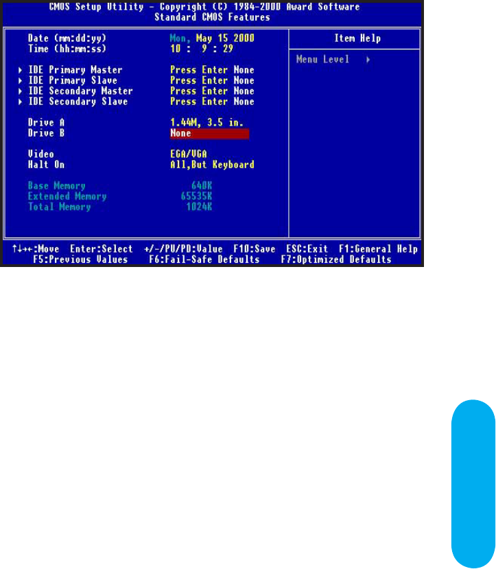
Time / Date
These fields provide you with the current date and time. Note that
the hour is displayed as a 24-hour clock. For example, 1:00 PM
is 13:00:00.
Floppy Drive A,
Floppy Drive B
This option selects the type of floppy drives installed.
Primary Master,
Primary Slave,
Secondary Master,
Secondary Slave
Standard CMOS Features
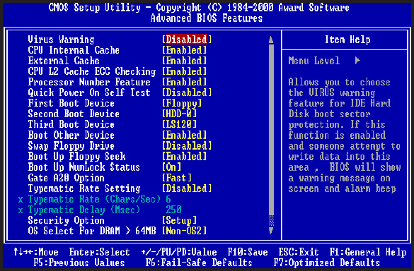
Advanced CMOS Features
Virus Warning
Enabled / Disabled Virus Warning function. Default setting is "Disabled".
CPU Internal Cache
External Cache
Enables processor on-chip L1 and L2 cache memory. Available settings are
WriteBack, Write-Thru and Disabled. Default is "WriteBack".
CPU L2 Cache ECC Cheeking
This option enables Error Checking and Correction (ECC) on the processor’s L2
cache bus. Default is "Disabled".
Quick Power on Self Test
When Enabled, BIOS will skip certain power-on self-test (POST) procedures
(such as memory test above 1MB) to speed up the boot process. Default
setting is "Disabled".
First / Second / Third Boot Device
Assign the priority of each storage device to be the boot-up drive. Supported
devices are IDE, Floppy, LS-120, ATAPI ZIP, CDROM, SCSI, NETWORK.
Default boot sequence is Floppy -> IDE-0 -> CDROM.
Mainboard User's ManualPage 22

Mainboard User's Manual Page 23
BIOS Setup
Boot Other Devices
Specifies whether BIOS to boot from other device not listed in the
1st/2nd/3rd Boot Device options when BIOS fail to boot from those
devices. Default setting is "YES".
Swap Floppy Drive
Set this option to "Enabled" to permit drives A: and B: to be swapped.
Default is "Disabled".
Boot Up Floppy Seek
Specify whether floppy drive A: will perform a Seek operation at system boot.
Default setting is "Disabled".
Boot Up NumLock Status
Set this option to "OFF" to turn the Num Lock key off when the computer
is booted so you can use the arrow keys on both the numeric keypad and
the keyboard. Default is "ON".
Gate A20 Option
Sets "Fast", lets chipset control Gate A20; Sets "Normal", lets a pin in the
keyboard controller control Gate A20. Default setting is "Fast".
Typematic Rate setting
Enabled / Disabled Typematic Rate setting, when enabled,the typematic rate
and typematic delay can be selected. Default setting is "Disabled".
Security Option
Enables password checking every time the computer is powered on or every
time BIOS Setup is executed. If System is chosen, a user password prompt
appears every time the computer is turned on. If "Setup" is chosen, the
password prompt appears if BIOS Setup is executed. Default is "Setup".
OS Select For Dram > 64MB
Set to "Enabled" if running OS/2 operating system and using more than
64MB system memory. Default is "Disabled".
Page 24 Mainboard User's Manual
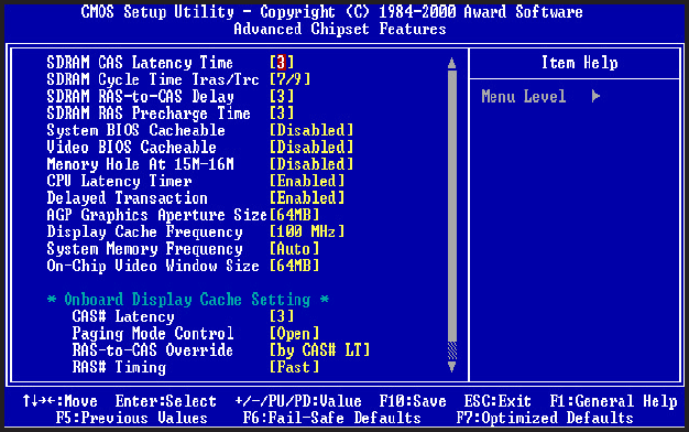
SDRAM CAS Latency Time
Specifies the number of SCLKs between the time when the Read command
is sampled by SDRAM and the Whitney Sample reads data from SDRAM.
Available settings are 3(SCLKs) or 2. Default is "3".
DRAM Cycle Time Tras/Trc
Specifies the length of the SDRAM cycle time in SCLKs. Available options
are 7/9, and 5/7. Default is "7/9".
SDRAM RAS-to-CAS Delay
Specifies the length of the delay inserted between the RAS and CAS signals
of the SDRAM system memory access cycle. The settings are Auto, 2 SCLKs
or 3 SCLKs. Default setting is "3".
SDRAM RAS Precharge Time
Specifies the length of the RAS precharge part of the SDRAM system
memory access. Available settings: Auto, 2 SCLKs, or 3 SCLKs. Default
setting is "3".
System BIOS Cacheable
Enabled / Disabled System BIOS cache. Default setting is "Enabled".
Video BIOS Cacheable
Enabled / Disabled Video BIOS cache. Default setting is "Enabled".
Memory Hole At 15M-16M
Enabled / Disabled Memory Hole at 15M-16M. Default is "Disabled".
Advanced Chipset Features

Mainboard User's Manual Page 25
BIOS Setup
CPU Latency Timer
Enables CPU BIST. Default is "Disabled".
Delayed Transaction
Enables / Disables ICH2 (I/O Controller Hub 2) delayed transactions
for internal register, Firmware Hub (FWH) and Low Pin Count (LPC)
interface accesses. Default is "Disabled".
AGP Graphics Aperture Size
Sets maximum memory aperture for onboard AGP port. Available settings
are 32MB and 64MB. Default is "64MB".
System Memory Frequency
Sets frequency of DIMM memory. Default is "AUTO".
On-Chip Video Window Size
Specifies amount of cache available for the graphics local memory
window. Available settings are 32MB and 64MB. Default is "64MB".
(815E only)
CAS# Latency
Sets number of SCLKs between the time when Read command is
sampled by DRAM and the Whitney Sample reads data from SDRAM.
Default is "Slow". (815E only)
Paging Mode Control
Enable / Disable Paging Mode. Default is "Closed". (815E only)
RAS-to-CAS Override
Sets delay override. Default is "Default". (815E only)
RAS# Timing
Sets clock frequency for RAS and RC. Default is "Slow". (815E only)
Page 26 Mainboard User's Manual
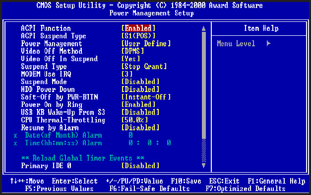
Power Management Setup
ACPI Function
Enabled/disabled ACPI Function. Default setting is "Disabled".
ACPI Suspend Type
Specifies ACPI Suspend type. Default setting is "S1(POS)"
Power Management
Specifies Power Management Mode. Default setting is "User Define".
Video Off Method
Specifies Video off Method. Default setting is "DPMS".
Video Off In Suspend
Specifies Video off in Suspend.
Suspend Type
Specifies Suspend Type. Default setting is "Stop Grant".
Modem Use IRQ
Sets Modem use IRQ
Suspend Mode
Specifies Suspend Mode. Default setting is "Disabled".

Mainboard User's Manual Page 27
BIOS Setup
HDD Power Down
Specifies HDD Power Down Mode. Default setting is "Disabled".
Soft Off by PWR_BTTN
Sets Power Down Mode by PWR_BTTN. Default setting is "Instant-off".
Wake-Up by PCI card
Enabled / Disabled Wake-up by PCI card. Default setting is "Disabled".
Power On by Ring
Enabled / Disabled Power on by Ring. Default setting is "Enabled".
USB KB Wake-up From S3
Enabled / Disabled USB KB Wake-up from S3. Default setting is "Disabled".
CPU Thermal-Throttling
Monitor CPU Temperature, slow down CPU Speed.
Resume by Alarm
Enabled / Disabled Resume by alarm. Default setting is "Disabled".
Primary IDE0
Enabled / Disabled monitor Primary IDE0 for Green event. Default setting
is "Disabled".
Primary IDE1
Enabled / Disabled monitor Primary IDE1 for Green event. Default setting
is "Disabled".
Secondary IDE0
Enabled / Disabled monitor Secondary IDE0 for Green event. Default setting
is "Disabled".
Secondary IDE1
Enabled / Disabled monitor Secondary IDE1 for Green event. Default setting
is "Disabled".
FDD.COM.LPT Port
Enabled/Disabled monitor FDD.COM.LPT for Green event. Default setting
is "Disabled".
PCI PIRQ [A-D]#
Enabled PCI PIRQIA-DJ#,Monitor PCI PIRQIA-DJ#IRQ Active,Disabled PCI
PIRQIA-DJ# Ignore PCI PIRQIA-DJ# IRQ Active. Default setting is "Disabled".
Mainboard User's ManualPage 28
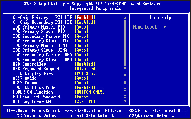
On-Chip Primary PCI IDE
Enabled / Disabled on-chip primary PCI IDE. Default setting is "Enabled".
On-Chip Secondary PCI IDE
Enabled / Disabled on-chip Secondary PCI IDE. Default setting is "Enabled".
IDE Primary Master / Slave PIO
IDE Secondary Master / Slave PIO
IDE Primary Master / Slave UDMA
IDE Secondary Master / Slave UDMA
Auto / Disabled IDE UDMA function feature. Default setting is "Auto", which
lets BIOS determine.
USB Controller
Enabled / Disabled USB Controller. Default setting is "Enabled".
USB Keyboard Support
Enabled / Disabled USB Keyboard Support. Default setting is "Disabled".
Init Display First
Default setting is "PCI Slot", sets Init Display First to PCI Slot.
AC97 Audio
Default setting is "Auto", BIOS will automatically detect onboard AC97 Audio.
Integrated Peripherals

BIOS Setup
Page 29 Mainboard User's Manual
AC97 Modem
Default setting is "Auto", BIOS will automatically detect onboard AC97
Modem.
IDE HDD Block Mode
Enabled / Disabled IDE HDD Block Mode. Default setting is "Enabled".
Power On Function
Specifies the keyboard hot key, mouse button, power button to wakeup the
computer from S3-S5 state. Available options are Button only: Password,
Hot key, Mouse left, Mouse right, Any key, keyboard 98. Default setting is
Button only.
KB Power On Password
Sets Keyboard Power on Password.
Hot Key Power On
Sets power on Hot key. Default setting is "Ctrl-F1".
On-board FDC Controller
Enabled / Disabled on-board FDC controller. Default setting is "Enabled".
Onboard Serial Port 1 & 2
Specify the I/O port addresses of serial port 1 and 2. Available settings are
Auto, Disabled, 3F8h, 2F8h, 3E8h and 2E8h. Default setting is "Auto".
UART Mode Select
Specifies the operation mode of onboard Serial Port 2. The onboard Serial Port
2 can be configured as an Infrared(IR) port or an ordinary RS-232 serial port.
Available settings are Normal, IrDA and ASKIR. Default is "Normal".
UR2 Duplex Mode
This option is not available when UART is set to "Normal". Available options
are Half Duplex and Full Duplex. Default setting is "Half Duplex".
Onboard Parallel Port
Specifies the I/O port address of the onboard parallel port. Available settings
are Auto, Disable, 378h, 278h and 3BCh. Default is "Auto".
Parallel Port Mode
Specifies the onboard parallel port mode. Available options are Normal, Bi-Dir,
ECP and EPP. Default is "ECP".
Mainboard User's ManualPage 30
EPP Mode Select
Specifies the Enhanced Parallel Port specification version number.
This option only appears if the Parallel Port Mode is set to "EPP". The
settings are 1.7 or 1.9. Default is N/A because the default setting for
the Parallel Port Mode option is not EPP.
ECP Mode USE DMA
This option only appears if the Parallel Port Mode option is set to
ECP. It assigns a DMA channel to the onboard parallel port. Available
settings are 1, 3. Default is "3".
Midi Port Address
Specifies the I/O address of the MIDI interface on the Onboard
Game Port. Available options are 300h, 330h 290h and Disabled.
Default is "330".
Midi Port IRQ
Assigns the IRQ line to the MIDI interface. Available options are 5 and
10. Default setting is "10". This option is not available if the Onboard
Midi Port is disabled S-232 serial port.
Game Port Address
Specifies the Onboard Game Port I/O address. Available settings are
201, 209, and Disabled. Default is "201".