Zida Technologies MB-A815EP-11 Mainboard User Manual Manual A815E1 indd
Zida Technologies Ltd. Mainboard Manual A815E1 indd
Contents
users manual 6
BIOS Setup
Page 31 Mainboard User's Manual
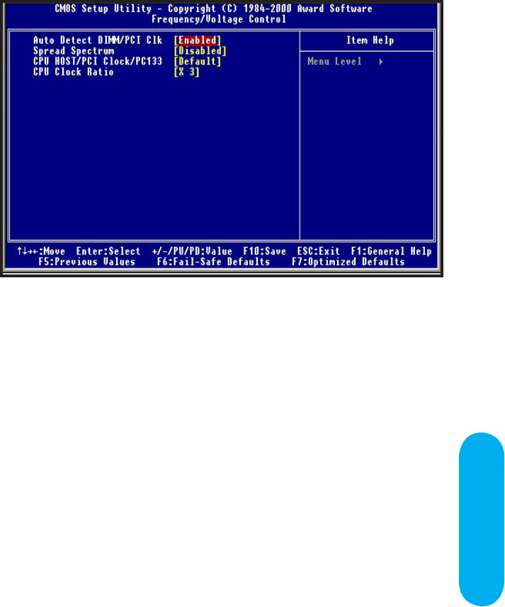
Auto Detect DIMM/PCI CLK
Enabled \ Disabled Auto detect DIMM\PCI CLOCK. Default setting
is "Enabled".
Spread Spectrum
This option turns on/off the clock generator’s Spread Spectrum
feature to reduce Electromagnetic Interference (EMI) generated by
high speed clock signals. Default setting is "Disabled".
CPU Host/PCI Clock/PC133
Select the clock generator’s Front Side Bus frequency for CPU
over-clocking. Default setting is "Default".
CPU Clock Ratio
Select CPU’s core/bus frequency ratio. This setting has no effect
on processors with frequency ratio locked. Available settings are
between 2x and 8x of the CPU BUS Speed. The ratio increases with
0.5 step. Default setting is "3x" (Safe).
Frequency / Voltage Control
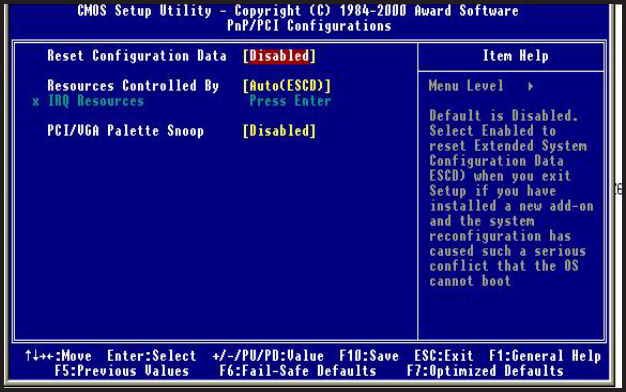
PnP/PCI Configurations
Reset configuration Data
Enabled \ Disabled Reset configuration Data. Default setting is
"Disabled".
Resources Controlled by
Sets the allocation of PCI resources. Available options are Manual and
Auto(ESCD). Default setting is "Auto"(ESCD). BIOS automatically
assigns resources.
IRQ Resources
When resources are controlled manually,assign each system interrupt
a type,depending on the type of device using the interrupt.
PCI/VGA Palette Snoop
Enabled / Disabled PCI / VGA Palette Snoop, sets Enabled for
having Video card on ISA Bus and VGA card on PCI Base, sets
"Disabled" for VGA card only.
Mainboard User's ManualPage 32

BIOS Setup
Page 33 Mainboard User's Manual
CPU Warning Temperature
Specifies CPU warning temperature value. Available options
are 50℃/122℉, 53℃/127℉,56℃/133℉, 60℃/140℉, 63℃/145℉,
66℃/151℉, 70℃/158℉ and Disabled. Default setting is "Disabled".
Current System Temperature
Current CPU Temperature
Detect System and CPU temperature automatically.
System Fan Speed
CPU Fan Speed
Chassis Fan speed
Detect Fan Speed Status automatically.
Vcore/Vft/VCC3-3/+5V/+12V/-12V
Detect System's Voltage status automatically.
Shutdown Temperature
This function will be effective only for the operating systems
that support ACPI Function. Specifies Shutdown Temperature
Value. Available option are 60℃/140℉, 65S℃/149℉, 70℃/158℉,
75℃/167℉ and Disabled. Default setting is "Default".
PC Health Status
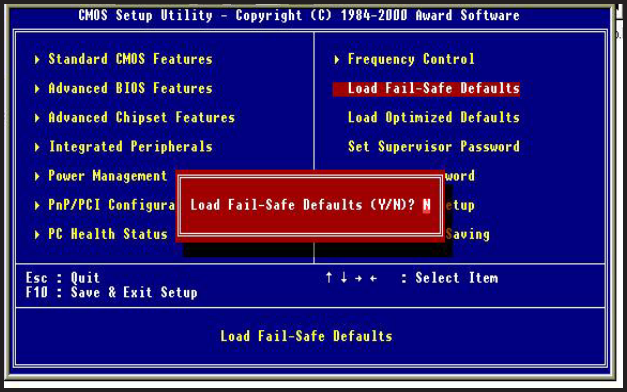
Fail-safe defaults contain the most appropriate values of the system
parameters that allow minimum system performance.
Load Fail-safe Defaults
Mainboard User's ManualPage 34
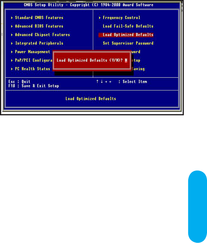
Load Optimized Defaults
Selecting this field loads the factory defaults for BIOS and Chipset
Features which the system automatically detects.
BIOS Setup
Page 35 Mainboard User's Manual
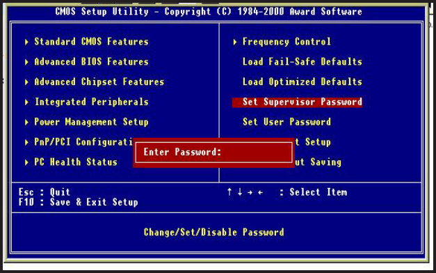
Set Supervisor / User password
When you select this function, the following message will appear at
the center of the screen to assist you in creating a password.
Type the password, up to eight characters and press<Enter>. The
new password will clear the previously entered password from
CMOS Memory, you will be asked to confirm the Password. Type
the password again and press <Enter>, you may also press <ESC>
to about the selection and not enter a password.
Mainboard User's ManualPage 36
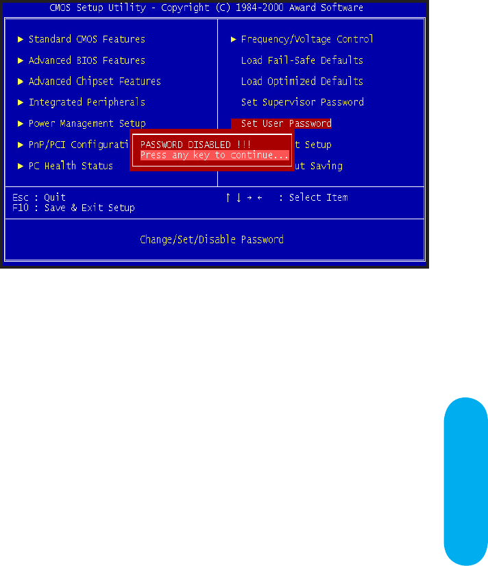
To disable password, just press <Enter> when you are prompted
to enter password. A Message <<PASSWORD DISABLED!!!>> will
appear to confirm the password being disabled. Once the password
is disabled, the system will boot and you can enter setup freely.
If you select "System" at "Security Option" in BIOS Features Setup
Menu, you will be prompted for the password every time. If you
select "Setup" at "Security option" in BIOS Features Setup Menu,
you will be prompted only when you try to enter Setup.
BIOS Setup
Page 37 Mainboard User's Manual
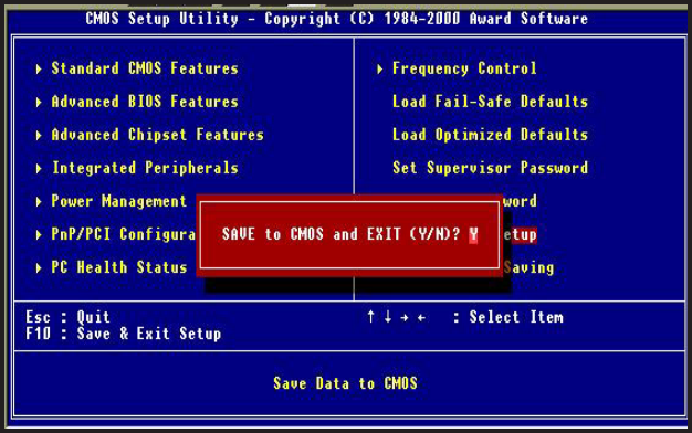
Type "Y" will quit the Setup Utility and Save the user setup value
to RTC CMOS.
Type "N" will return to Setup Utility.
Save & Exit Setup
Mainboard User's ManualPage 38
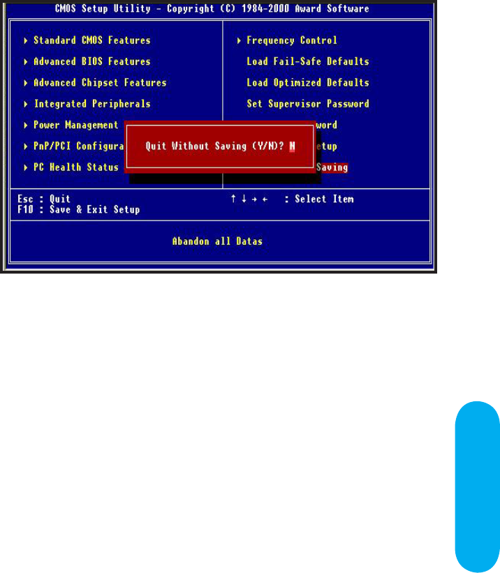
Type "Y" will quit the Setup Utility and Without Saving the User
setup Value.
Type "N" will return to Setup Utility.
Exit Without Saving
BIOS Setup
Page 39 Mainboard User's Manual

Glossary
A PS/2 Mouse & Keyboard Connector
The Mainboard provides two on-board PS/2 connectors, one for
the keyboard, and one for the mouse. PS/2 devices all have
a standard 6-pin round shape connector. If you are already
using a PS/2 mouse or keyboard, simply plug them into the
corresponding connector. No jumper settings are necessary.
B ATX Power Supply Connector
The Mainboard provides a single 20-pin ATX power supply
connector, which incorporates standard +5V and +12V, 3.3V
and soft-on/off signals. With a power supply that supports
remote power on/off, the mainboard can turn off the system
power through software control, such as the shutdown command
in the Windows 95 / Windows 98 Start Menu. The BIOS
system will turn the system power off when it receives the
proper APM command from the OS. APM must be enabled in
the BIOS and OS systems in order to set the soft-off feature
working properly.
Pin Signal Name Pin Signal Name
1 +3.3V 11 +3.3V
2 +3.3V 12 -12V
3 Ground 13 Ground
4 +5V 14 PW_ON
5 Ground 15 Ground
6 +5V 16 Ground
7 Ground 17 Ground
8 PWRGOOD 18 -5V
9 +5VSB 19 +5V
10 +12V 20 +5V
Glossary
Page 41 Mainboard User's Manual
Glossary

Mainboard User's ManualPage 42
About the Soft Touch Power Button
In an ATX based system, the new soft touch power button
replaces the main power switch that turns your system on and
off. From an OFF state, you can switch the system ON by simply
pressing the power button. From an ON state, the system can
be turned OFF by pressing and holding the power button for four
(4) seconds OR shut down instantly. The functions of the power
button can also be altered in the Power Management section
of the CMOS setup.
C Universal Serial Bus (USB) Connector
The Mainboard provides four 4-pin Universal Serial Bus
(USB) connectors. USB is a new interface standard for adding
external Plug-and-Play (PnP) devices to the computer system.
Peripherals that support USB PnP capabilities can operate at up
to a 12Mb/sec data transfer rate. Eventually, all external devices
connected to your computer will be standardized to USB.
D Serial (COM1 & 2) Connector
The Mainboard provides two high-speed 16550 compatible UART
serial ports.
E Infra-Red (IR) Header
The Mainboard provides a 5-pin header interface, IR
for connection to a Hewlett Packard HSDSL-1000 compatible
infrared (IrDA) transmitter/receiver. Connect IR to the front panel
I/O IrDA connector provided with your system. Once the module
is connected to the front panel I/O IrDA connector, Serial port
2 can be re-directed to the IrDA module. When configured for
IrDA, the user can transfer files to or from portable devices such
as laptops, PDA’s and printers using application software such as
LapLink. The IrDA specification provides for data transfers at 115
kbps from a distance of 1-meter. Support for Consumer infrared
(ASK-IR) is also included. Please refer to your IR equipment for
more detailed information.

Glossary
The header pin-out is as follows:
Pin . . . . . . . . . . . . . Signal Name
1 . . . . . . . . . . . . . . . VCC, power source
2 . . . . . . . . . . . . . . . No Connection
3 . . . . . . . . . . . . . . . IRRX, infra-red receive
4 . . . . . . . . . . . . . . . Ground
5 . . . . . . . . . . . . . . . IRTX, infra-red transmit
F Memory Module Sockets
The Mainboard provides 168 pin standard DIMM sockets for
installation of 3.3V unbuffered Single or Double Bank SDRAM
modules.
G Parallel Port Connector
The ATX Mainboard provides a parallel port connector. Based
on the ATX standard, a 25-pin parallel port is now built on
the mainboard back panel. This design makes the mainboard
installation easier. The parallel port can be BIOS configured
into standard (SPP) mode, Enhanced Parallel Port (EPP) mode,
and a high speed Extended Capabilities Port (ECP) mode. EPP
Mode requires a driver provided by the peripheral manufacturer
in order to operate properly.
H Accelerated Graphics Port [AGP] Connector
The Mainboard provides an AGP slot compatible with the
Accelerated Graphics Port specification. AGP compliant video
cards offer a much higher throughput than equivalent PCI bus
video cards. PCI currently only supports a 33MHz bandwidth,
and can transport at peak rates up to 133MB/s over its 32
bit data bus. AGP operates at a 66MHz bandwidth which
enables a peak rate of 266MB/s in what is known as 'X1'
mode. Using 'X2' mode, the peak transport rate can go as
high as 532MB/s.
Page 43 Mainboard User's Manual
90-A815E1-A1-00
I LITHIUM BATTERY
A 3V, CR2032, Lithium battery is installed on the on-board
battery socket. This battery is used to supply the CMOS
RAM backup power during system powered-off. Danger of
explosion if battery is incorrectly replaced. Therefore, if you
have any difficulties, please consult the technical personnel.
J PCI Add-In Board Connector
The Mainboard provides 5 PCI Connector for the PCI cards.
L Modem Connector (Optional)
Connect the "MODEM connector" to the Telephone Jack extension
cable for the optional onboard 56Kbps modem.
M Front Panel Function Connector
The Mainboard integrates all system front panel functions into
a single on-board connector. These include connections for the
following features:
Function Connector Pin-Out Label
System Reset RESET
Power LED / Keylock PW-LED
Hard Drive Activity LED HD_ LED
Soft-Touch Button Power On/Off PW-BN
External Power Saving Control (optional) EXTSMI
Sleep Button SLPBTN
suspend LED Sus-Led
External speaker Speaker
Pw-Bn
Pw-Led Extsmi
Hd-Led
Keylock
Sus-Led
Speaker
Reset
CN2
Glossary
N Flash BIOS
The Mainboard flash BIOS provides users with more flexibility
in upgrading their mainboards. The flash BIOS can be easily
reprogrammed via software.
O Floppy Drive Header
The Mainboard provides a 34-pin connector that supports
the included floppy drive ribbon cable. After connecting the
single end to the on-board “FLOPPY” connector, connect
the remaining plugs on the other end of the cable to the
corresponding floppy drives.
NOTE: Pin 5 is removed to prevent inserting the connector
in the wrong orientation.
P IDE Device Header
The Mainboard provides (2) independent bus-mastering PCI
IDE interfaces capable of supporting up to Mode 4 and Ultra
DMA-33/66/100 devices. The system BIOS supports automatic
detection of the IDE device data transfer rate and translation
between different kinds of device modes such as Logical Block
Addressing (LBA), Extended Cylinder Sector Head (ECSH)
translation modes and ATAPI (e.g., CD-ROM) devices on both
IDE interfaces.
The two on-board IDE headers support the provided 80-pin IDE
hard disk ribbon cables. If you install two hard disks and/or
CD-Rom drives, you must configure the two drives by setting
their IDE master/slave jumpers according to the documentation
for those devices.
Also, you may connect the two hard disk drives so that both
become Masters, using one ribbon cable on the primary IDE
header and one on the secondary IDE header.
Page 45 Mainboard User's Manual
Q WAKEUP-LINK Header
The Mainboard provides on WAKEUP-LINK header (WOL)
used to connect an add-in Network Interface Card which has
Wakeup capability.
R Universal Serial Bus Header
Connect this header to the optional USB extension cable for
two USB ports.
r "CNR" Add-in Board Connector
Communication & Networking Riser(CNR) is a new interface
standard for Networking or modem add-in card.
S CPU Socket
The Mainboard provides a 370-pin CPU Socket for Intel
Celeron, PIII or Cyrix III processor. The CPU should have a fan
attached to it to prevent overheat. If a fan is not present, a fan
should be installed prior to turning the system on.
Mainboard User's ManualPage 46
Glossary
T CPU / System & Auxiliary Fan Connector
The recommended heatsink for the processor are those
with 12 Volt three-conductor fan that can be connected to the
fan connector on the mainboard. It provides +12 Volts DC to
the CPU cooling fan as follows:
PIN SIGNAL NAME
1 Ground
2 +12V
3 FAN Speed Detect
CAUTION! Be sure that sufficient air circulation is available across the
processor’s heatsink by regularly checking that your CPU fan is
working. Without sufficient circulation, the processor could overheat
and damage both the processor and the mainboard. You may install
an auxiliary fan if necessary.
The SYSTEM and AUXILIARY fan connectors are provided for
optional cooling fans.
U Audio & Joystick Connectors
The Mainboard provides Audio headers.
Audio & Joystick Connectors
Line Output
Line Input
Microphone Input
Game Port
Page 47 Mainboard User's Manual

V VGA Connector (Optional)
Connect this connector to the VGA extension cable for integrated
VGA interface (815E only).
W Temperature Sensor Header
The mainboard provides one header for an optional thermal
sensor to monitor system temperature.
X CD Audio Connector
CD Audio input ( Right, Ground, Ground, Left )
Y Auxiliary Audio Connector
Auxiliary input ( Right, Ground, Ground, Left )
z Case Detect
If case is opened,this switch should be closed.
Mainboard User's ManualPage 48

Mainboard User's Manual Page 49
CD Driver & Software Installation Guide
Steps :
1. Boot up the Operating System ( Windows 95/98/NT/2000 )
2. Put the CD Disc into the CD-ROM Drive and wait for Autorun
3. Select A815E / A815EP and click your Operating System Type
4. Follow the instructions and install suitable drivers
CD Driver & Software
Installation Guide