Zida Technologies MB-A815EP-11 Mainboard User Manual Manual A815E1 indd
Zida Technologies Ltd. Mainboard Manual A815E1 indd
Contents
users manual 2

Overview
Thank You for purchasing our High Performance Mainboard.
Our advanced technology mainboard is designed for processing
speeds of 933MHz or above and is upgradeabled for future
processors.
The Intel Mainboard Utilizes 815E/815EP and ICH2 chipset
provide an Integrated Bus Mastering IDE controller with two
high performance IDE interfaces for up to four UDMA IDE
devices (hard drives, or CD-ROM's). The LPC(Low-pin count)
I/O controller integrates a floppy drive interface, two enhanced
16C550 compatible serial ports, one parallel port and one
consumer infra red compatible interface.The ICH2 I/O controller
integrates two USB 1.1 compliant controllers with a total of
4 ports.
Intel 815E chipset support Intel Celeron,Intel Pentium Ⅲ and
Cyrix III processors on socket 370 with 100/133 SDRAM
DIMM.
Three DIMM slots support up to 512MB Memory Capacity.
WAKEUP-LINK Header supports Wake-On-LAN.
Integrated AC97 2.1 Compliant Codec with 3D Stereo
enhancement (optional). Award 4M bits Firmware Hub compliant
with PC99,ACPI//DMI power management.
ATX 305mm x 210mm.
Mainboard User's Manual Page 5
Overview
Page 6 Mainboard User's Manual
Fast Start
Installation
This section will aid you in quickly setting up the Mainboard.
Be sure to take caution to avoid personal injury or damage
to wiring due to sharp pins on connectors, printed circuit
assemblies, rough edges and corners and hot components.
Your Location Requirements Are:
• A sturdy, level surface for placement
• Space allowance around mainboard
• A stable environment with no abrupt temperature or humidity
changes
• No exposure to chemicals or direct sunlight
• Line voltage and frequency not varying more than + or -10% from
the value stated on the package or nameplate (located on the
back, opposite the power plug)

Checking
The Package Contents
Remove the items from the box and make sure you have
the following items before beginning. If any of the items
below are missing, please contact the representative for part
replacement.
ATX Box Standard Package
1) Mainboard
2) Driver CD with Norton AntiVirus 2001 OEM Version
3) User Manual
4) IDE Hard Drive Ribbon Cable
5) Floppy Drive Ribbon Cable
6) USB Cable for onboard USB Header ( Optional )
7) Modem Cable for Modem Header ( Optional )
Installation
Mainboard User's Manual Page 7
Page 8 Mainboard User's Manual
Mainboard
Diagram

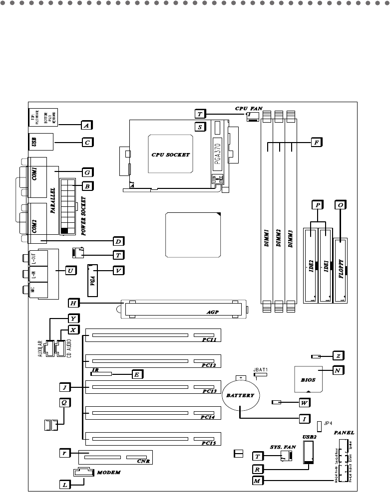
Before we begin installing your series Mainboard, we have provided you with a diagram of the Mainboard to
help you locate the appropriate “connectors”. The letters below describe the key Mainboard components.
Page number in the right hand column will direct you to detailed description of the component.
A815E / A815EP
Option : AC97 2.1 Compliant 3D Audio
Software 56K Modem
Onboard
COMPONENT PAGE
A- PS/2 Mouse & Keyboard Connector . . . . . . . . . . . . . . . . . . 41
B- ATX Power Supply Connector . . . . . . . . . . . . . . . . . . . . . . 41
C- Universal Serial Bus (USB) Connector . . . . . . . . . . . . . . . 42
D- Serial (COM1 & 2) Connector . . . . . . . . . . . . . . . . . . . . . . . 42
E- Infra-Red (IR) Header . . . . . . . . . . . . . . . . . . . . . . . . . . . . . 42
F- Memory Module Sockets . . . . . . . . . . . . . . . . . . . . . . . . . . . 43
G- Parallel Port Connector . . . . . . . . . . . . . . . . . . . . . . . . . . . . 43
H- Accelerated Graphics Port (AGP) Connector . . . . . . . . . . 43
I- Lithium Battery . . . . . . . . . . . . . . . . . . . . . . . . . . . . . . . . . . 44
J- PCI Add-in Board Connector . . . . . . . . . . . . . . . . . . . . . . . 44
L- Modem Connector (Optional) . . . . . . . . . . . . . . . . . . . . . . . 44
M- Front Panel Function Connector . . . . . . . . . . . . . . . . . . . . . 44
N- Flash BIOS . . . . . . . . . . . . . . . . . . . . . . . . . . . . . . . . . . . . . 45
O- Floppy Drive Header . . . . . . . . . . . . . . . . . . . . . . . . . . . . . . 45
P- IDE Device Header . . . . . . . . . . . . . . . . . . . . . . . . . . . . . . . 45
Q- WAKEUP-LINK Header . . . . . . . . . . . . . . . . . . . . . . . . . . . . 46
R- Universal Serial Bus Header . . . . . . . . . . . . . . . . . . . . . . . . 46
r- CNR Add-in Board Connector . . . . . . . . . . . . . . . . . . . . . . . 46
S- CPU Socket . . . . . . . . . . . . . . . . . . . . . . . . . . . . . . . . . . . . 46
T- CPU / SYSTEM & AUXILIARY FAN Connector . . . . . . . . . 47
U- Audio & Joystick Connectors . . . . . . . . . . . . . . . . . . . . . . . 47
V- VGA Header (Optional) . . . . . . . . . . . . . . . . . . . . . . . . . . . . 48
W- Temperature Sensor Header . . . . . . . . . . . . . . . . . . . . . . . . 48
X- CD Audio Connector . . . . . . . . . . . . . . . . . . . . . . . . . . . . . . 48
Y- Auxiliary Audio Connector . . . . . . . . . . . . . . . . . . . . . . . . . . 48
z- Case Detect . . . . . . . . . . . . . . . . . . . . . . . . . . . . . . . . . . . . 48
Mainboard User's Manual Page 9
Installation