Zida Technologies MB-A845 Tomato User Manual 90 A845S1 00 00 indd
Zida Technologies Ltd. Tomato 90 A845S1 00 00 indd
Contents
- 1. users manual 1
- 2. users manual 2
- 3. users manual 3
- 4. users manual 4
users manual 2
7 Quick Steps
Page 15 Mainboard User's Manual
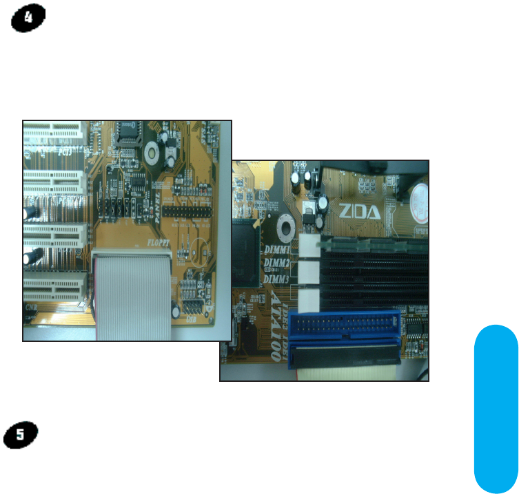
Floppy Disk Drive Header (34-pin FLOPPY).
This is a 34-pin header that supports the provided floppy
drive ribbon cable. After connecting the single end to the
on-board “FLOPPY” header, (O in Mainboard Diagram) connect
the remaining plugs on the other end to the corresponding
floppy drives.
IDE Device Headers
The on-board IDE headers (P in Mainboard Diagram) support
the provided 40/80-pin IDE hard disk ribbon cable. After
connecting the single end to the mainboard, connect the
remaining plugs at the other end of your hard disk(s). When
installing hard disks, you must configure the drives by setting
their jumpers according to the documentation of your hard
disk.
You may also connect the hard disk drives so that both
become Masters, using one ribbon cable on the primary IDE-
header, and the other on the secondary IDE header.
NOTE: Please make sure that the pin 1 of the ribbon cable
the red wire side of the cable) is correctly connected to
the on-board header pin 1 as shown on the “mainboard
diagram”.
Floppy connection
IDE connection
Page 16 Mainboard User's Manual
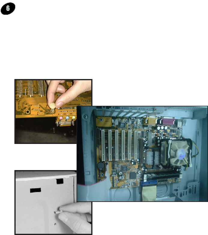
Mounting Mainboard to chassis
Snap the black mounting pins onto the mainboard as shown.
Carefully install the mainboard into the computer chassis and align
the corresponding mounting holes on the mainboard with the holes
on your chassis. While chassis design varies you may need to
refer to the chassis manual for the mainboard mounting area.
Insert white pins through the chassis and through the mounting
holes on the mainboard into the black pin making sure they are
snapped fully into place.
Insert black mounting pin
Insert into chassis
Insert white mounting pin
Mainboard User's Manual Page 17
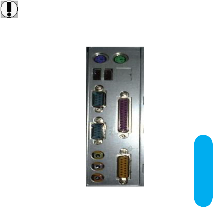
Make sure to align rear external I/O connector's with
the corresponding openings in chassis shown below
(A, C, G, U in Mainboard Diagram)
7 Quick Steps
Mainboard User's ManualPage 18
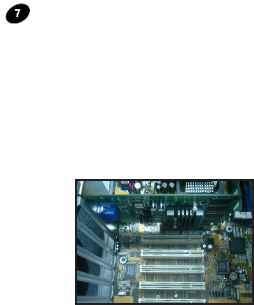
PCI Board Installation
Installing Add-in Boards
First read your expansion card documentation for hardware and
software settings that may be required to set up your specific
card. Set any necessary jumpers on your expansion card and
remove the cover plate on your computer case at the slot
you intend to use. Keep the plate for possible future use.
Carefully align the card's connector and press firmly. Secure
the card on the slot with the screw you removed from the
cover plate.
You can now attach the appropriate wires for the switches, LEDs
and speaker to the Front Panel Function header (M in Mainboard
Diagram). Then, connect the I/O devices (such as keyboard, mouse
and monitor) to the appropriate rear external I/O connectors. Connect
the main power cable and ready to boot your system.
Press the DEL key when prompted and continue BIOS configurations
discussed in the next chapter.

BIOS
Setup
Mainboard User's ManualPage 20
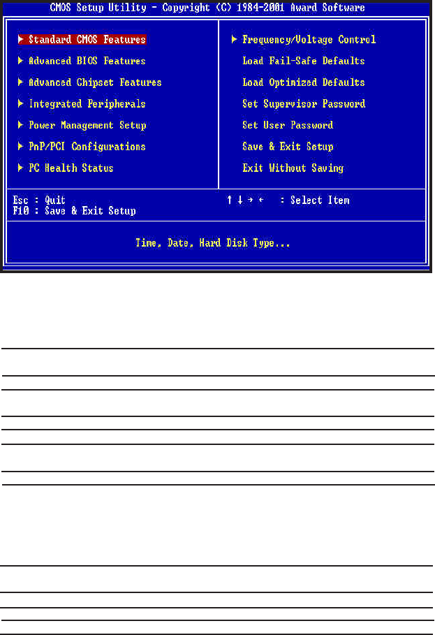
Standard CMOS Features
Advanced BIOS Features
Advanced Chipset Features
Integrated Peripherals
Power Management Setup
PnP/PCI Configurations
PC Health Status
Frequency/Voltage Control
Load Fail-Safe Defaults
Load Optimized Defaults
Setup Supervisor Password
Setup User Password
Save & Exit Setup
Exit Without Saving
Set time & date, hard disk drive floppy drive and
Monitor types.
Select system boot sequence, floppy control, CPU
cache settings, Shadow RAM.
Configure chipset specific options and features.
Configure onboard I/O device addresses and operating
modes.
Select various power saving options.
Set PCI Plug and Play device options.
Report system / CPU temperature and cooling fans
status.
Select CPU frequency ratio.
Load settings that are more likely to configure a
workable computer when something is wrong. If you
cannot boot the computer successfully, select the
Fail-Safe option and try to diagnose the problem after
the computer boots. These settings do not provide
optimal performance.
Load settings that provide best performance charac-
teristic. (Default factory settings)
Change / Add / Remove supervisor password.
Change / Add / Remove user password.
Save Data to CMOS
Abandon all saving
Award BIOS Setup
BIOS Setup
Page 21 Mainboard User's Manual
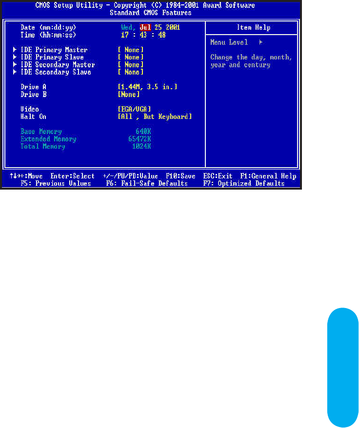
Date / Time
These fields allow you to set the current date and time. Note that the hour is
displayed as a 24-hour clock. For example, 1:00 PM is 13:00:00.
IDE Primary Master,
IDE Primary Slave,
IDE Secondary Master,
IDE Secondary Slave
These options enter another menu for hard disk detection.
Floppy Drive A,
Floppy Drive B
These options select the type of floppy drives installed. The options are :
"None", "360K, 5.25in", "1.2M, 5.25in", "720K, 3.5in", "1.44M, 3.5in", "2.88M,
3.5in".
Video
This field allows you to select monitor type. Options are : "MONO", "CGA40",
"CGA80" and "EGA/VGA".
Halt On
Allow the system to halt during BIOS boot up when error occurs.
Options are "All, But keyboard", "All, But Diskette", "All, But Disk / Key",
"No errors", "All Errors".
Base Memory, Extended Memory, Total Memory
Display the current size of memory installed.
Standard CMOS Features
Advanced BIOS Features
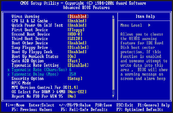
Virus Warning
Enabled / Disabled Virus Warning function. Default setting is "Disabled".
CPU L1 & L2 Cache
Enabled / Disabled CPU internal L1 & L2 cache. Default setting is "Enabled".
Quick Power On Self Test
When Enabled, BIOS will skip certain power-on self-test (POST) procedures
(such as memory test above 1MB) to speed up the boot process. Default
setting is "Enabled".
First / Second / Third Boot Device
Assign the priority of each storage device to be the boot-up drive. Supported
devices are IDE, Floppy, LS-120, ZIP100, CDROM, SCSI, LAN or Disabled.
Default boot sequence is Floppy -> IDE-0 -> LS-120.
Boot Other Device
Specifies whether BIOS to boot from other device not listed in the 1st/2nd/3rd
Boot Device options when BIOS fail to boot from those devices. Default setting
is "Enabled".
Swap Floppy Drive
Sets this option to "Enabled" to permit drives A: and B: to be swapped. Default
setting is "Disabled.
Mainboard User's ManualPage 22

Mainboard User's Manual Page 23
BIOS Setup
Boot Up Floppy Seek
Specify whether floppy drive A: will perform a Seek operation at system boot. Default
setting is "Enabled".
Boot Up NumLock Status
Sets this option "OFF" to turn the Num Lock key off when the computer is booted
such that you can use the arrow keys on both the numeric keypad and the keyboard.
Set this option to "ON" to enable the numeric pad when the system is turned on.
Default is "ON".
Gate A20 Option
Sets "Fast" to allow chipset to control Gate A20; Sets "Normal", to let a pin in the
keyboard controller to control Gate A20. Default setting is "Fast".
Typematic Rate Setting
Enabled / Disabled Typematic Rate setting, when enabled, the typematic rate and
typematic delay can be selected. Default setting is "Disabled".
Security Option
Enables password checking every time the computer is powered on or every time
BIOS Setup is executed. If System is chosen, a user password prompt appears every
time the computer is turned on. If "Setup" is chosen, the password prompt appears if
BIOS Setup is executed. Default setting is "Setup".
APIC Mode
Enable / Disable APIC (Advanced Programmable Interrupt Controller) functions.
Default setting is "Enabled".
MPS Version Control For OS
Options are 1.1 and 1.4
OS Select For DRAM > 64MB
Sets to "OS2" if running OS/2 operating system and using more than 64MB system
memory. Default setting is "Non-OS2".
Report No FPP for WIN 95
Selects "Yes" when the system is running Windows 95 and no floppy driver is installed.
Otherwise, leave it as default "No".
Small Logo (EPA) Show
Enable / Disable EPA logo to be shown during boot up.
Page 24 Mainboard User's Manual
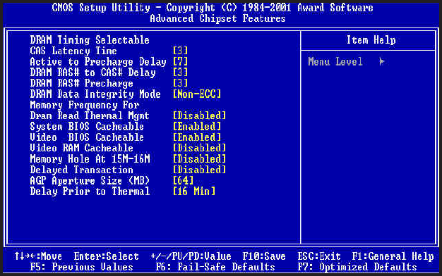
DRAM Timing Selectable
Manual / By SPD. Select "By SPD" to allow BIOS to get the optimized timing
data from the data stored on the DIMM modules. Otherwise, select "Manual" to
configure the following timing constraints.
CAS Latency Time
Specifies the number of SCLKs between the time when the Read command is
sampled by DRAM and the Whitney Sample reads data from DRAM. Available
settings are 2, 3. Default setting is "3".
Active to Precharge Delay
Specifies the active to precharge delay : The settings are 7, 6, 5. Default
setting is "7".
DRAM RAS-to-CAS Delay
Specifies the length of the delay inserted between the RAS and CAS signals
of the DRAM system memory access cycle. The settings are 2 SCLKs or 3
SCLKs. Default setting is "3".
DRAM RAS Precharge
Specifies the length of the RAS precharge part of the DRAM system memory
access. Available settings: 2 SCLKs, or 3 SCLKs. Default setting is "3".
Advanced Chipset Features

Mainboard User's Manual Page 25
BIOS Setup
DRAM Data Integrity Mode
Display Integrity mode of the DIMM modules. Options are Non-
ECC/ECC. Defaults setting is "Non-ECC".
Memory Frequency For
Sets frequency of DIMM memory. Default is "AUTO".
Dram Read Thermal Mgmt
Select "Enabled" to allow Dram Read Thermal Mgmt to manage
DRAM speed according to it's temperature. Once the DRAM
temperature increases to a specific level, Thermal Mgmt will slow
down DRAM speed for a certain period of time (can be specific
in "Delay Prior to Thermal") in order to cool down the DRAM.
After the delay time is up, Thermal Mgmt will check for the DRAM
temperature to determine whether to change DRAM speed back to
its normal operation speed or not.
Default setting is "Disabled".
System BIOS Cacheable
Enabled / Disabled System BIOS cache. Default setting is
"Enabled".
Video BIOS Cacheable
Enabled / Disabled Video BIOS cache. Default setting is
"Enabled".
Video RAM Cacheable
Enabled / Disabled Video RAM cache. Default setting is
"Disabled".
Memory Hole At 15M-16M
Enabled / Disabled Memory Hole at 15M-16M. Default setting
is "Disabled".
Delayed Transaction
Enables / Disables ICH2 (I/O Controller Hub 2) delayed transactions for
internal register, Firmware Hub (FWH) and Low Pin Count (LPC) interface
accesses. Default setting is "Disabled".
AGP Aperture Size
Sets maximum memory aperture for onboard AGP port. Available settings
are 4MB, 8MB, 16MB, 32MB, 64MB, 128MB and 256MB. Default setting
is "64MB".
Delay Prior to Thermal
You must have "Dram Read Thermal Mgmt" option enabled in order for this
option to be meaningful. This option sets the time between each DRAM
Thermal detections once the Thermal Mgmt activates. Options are 4min /
8min / 16min / 32min. Default setting is "16 Min".
System BIOS Protect
Enabled to protect system BIOS from overwritten.
Mainboard User's ManualPage 26
Mainboard User's Manual Page 27
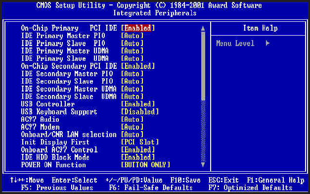
On-Chip Primary PCI IDE
Enabled / Disabled on-chip primary PCI IDE. Default setting is "Enabled".
On-Chip Secondary PCI IDE
Enabled / Disabled on-chip Secondary PCI IDE. Default setting is "Enabled".
IDE Primary Master / Slave PIO
IDE Secondary Master / Slave PIO
Specify the IDE mode for the system.
IDE Primary Master / Slave UDMA
IDE Secondary Master / Slave UDMA
Auto / Disabled IDE UDMA function feature. Default setting is "Auto", which
lets BIOS determine.
USB Controller
Enabled / Disabled USB Controller. Default setting is "Enabled".
USB Keyboard Support
Enabled / Disabled USB Keyboard Support. Default setting is "Disabled".
AC97 Audio
Default setting is "Auto", BIOS will automatically detect onboard AC97 Audio.
AC97 Modem
Default setting is "Auto", BIOS will automatically detect onboard AC97 Modem.
Integrated Peripherals
Page 28 Mainboard User's Manual
Init Display First
Default setting is "PCI Slot", sets Init Display First to PCI Slot or AGP Slot.
Onboard / CNR LAN Selection
Selects "onboard' to enable the optional onboard LAN function. Selects "Ext.
CNR" to disable onboard LAN function and uses LAN function on CNR card.
Onboard AC97 Control
Enabled / Disabled the onboard AC97 audio controller. Default setting is
"Enabled".
IDE HDD Block Mode
Enabled / Disabled IDE HDD Block Mode. Default setting is "Enabled".
Power ON Function
Specifies the keyboard hot key, mouse button, power button to wakeup the
computer from S3-S5 state. Available options are : Button only, Password,
Hot key, Mouse left, Mouse right, Any key, keyboard 98. Default setting is
Button only.
KB Power ON Password
Sets Keyboard Power on Password.
Hot Key Power On
Sets power on Hot key. Default setting is "Ctrl-F1".
On-board FDC Controller
Enabled / Disabled on-board FDC controller. Default setting is "Enabled".
Onboard Serial Port 1 & 2
Specify the I/O port addresses of serial port 1 and 2. Available settings are Auto,
Disabled, 3F8h, 2F8h, 3E8h and 2E8h. Default setting is "Auto".
UART Mode Select
Specifies the operation mode of onboard Serial Port 2. The onboard Serial Port
2 can be configured as an Infrared(IR) port or an ordinary RS-232 serial port.
Available settings are Normal, IrDA and ASKIR. Default is "Normal".
RxD, TxD Active
Options are "Hi,Hi", "Hi,Lo" / "Lo,Hi" and "Lo,Lo".
IR Transmission Delay