Zida Technologies MB-A845 Tomato User Manual 90 A845S1 00 00 indd
Zida Technologies Ltd. Tomato 90 A845S1 00 00 indd
Contents
- 1. users manual 1
- 2. users manual 2
- 3. users manual 3
- 4. users manual 4
users manual 4

Glossary
Mainboard User's Manual Page 43
4-pin ATX Power Supply
Pin Signal Name
1 Ground
2 Ground
3 +12V
4 +12V
About the Soft Touch Power Button
In an ATX based system, the new soft touch power button
replaces the main power switch that turns your system on and
off. From an OFF state, you can switch the system ON by
simply pressing the power button. From an ON state, the system
can be turned OFF by pressing and holding the power button
for four (4) seconds OR shut down instantly. The functions of
the power button can also be altered in the Power Management
section in the BIOS setup.
C Universal Serial Bus (USB) / Lan (Optional)
Connector
The Mainboard provides Two 4-pin Universal Serial Bus
(USB) connectors. USB is a new interface standard for adding
external Plug-and-Play (PnP) devices to the computer system.
Peripherals that support USB PnP capabilities can operate at up
to a 12Mb/sec data transfer rate. Eventually, all external devices
connected to your computer will be standardized to USB.

Mainboard User's ManualPage 44
Your mainboard may come with an optional onboard LAN func-
tion. It utilizes the Intel 82562ET Physical Layer Interface,
which is IEEE 10BASE-T and 100BASE-TX compliant. If your
mainboard does come with an onboard LAN function, make sure
it is enabled in the BIOS setting under “Integrated Peripherals” in
order to use it. If you rather install and use the LAN function on
the CNR card, make sure you disable the onboard LAN function
and select “EXT. CNR” in the BIOS setting. The reason being
that they both share the same LAN controller on the ICH2 chip.
Only one physical layer interface can uses the LAN controller at
a time, otherwise conflict will occur.
c Universal Serial Bus (USB) Header
Connect this header to the optional USB extension cable for
a USB port.
D Serial (COM1 & 2) Headers
The Mainboard provides two 9-pins serail port headers.
E Infrared (IR) Header
The Mainboard provides a 5-pin header interface, IR
for connection to a Hewlett Packard HSDSL-1000 compatible
infrared (IrDA) transmitter/receiver. Connect IR to the front panel
I/O IrDA connector provided with your system. Once the module
is connected to the front panel I/O IrDA connector, Serial port
2 can be re-directed to the IrDA module. When configured for
IrDA, the user can transfer files to or from portable devices such
as laptops, PDA’s, mobile phone and printers using application
software such as LapLink. The IrDA specification provides for
data transfers at 115 kbps from a distance of 1-meter. Support
for Consumer infrared (ASK-IR) is also included. Please refer to
your IR equipment for more detailed information.

Glossary
The header pin-out is as follows:
Pin . . . . . . . . . . . . . Signal Name
1 . . . . . . . . . . . . . . . VCC, power source
2 . . . . . . . . . . . . . . . No Connection
3 . . . . . . . . . . . . . . . IRRX, infrared receive
4 . . . . . . . . . . . . . . . Ground
5 . . . . . . . . . . . . . . . IRTX, infrared transmit
F Memory Module Sockets
The Mainboard provides 168 pin standard DIMM sockets for
installation of 3.3V unbuffered Single or Double Bank SDRAM
modules.
G Parallel Port Connector
The ATX Mainboard provides a parallel port connector. Based
on the ATX standard, a 25-pin parallel port is now built on
the mainboard back panel. This design makes the mainboard
installation easier. The parallel port can be BIOS configured
into standard (SPP) mode, Enhanced Parallel Port (EPP) mode,
and a high speed Extended Capabilities Port (ECP) mode. EPP
Mode requires a driver provided by the peripheral manufacturer
in order to operate properly.
H Accelerated Graphics Port [AGP] Connector
The Mainboard provides an AGP slot compatible with the
Accelerated Graphics Port specification. AGP compliant video
cards offer a much higher throughput than equivalent PCI bus
video cards. PCI currently only supports a 33MHz bandwidth,
and can transport at peak rates up to 133MB/s over its 32 bit
data bus. AGP operates at a 66MHz bandwidth which enables
a peak rate of 266MB/s in what is known as 'X1' mode. 'X2'
mode has a peak rate of 532MB/S. 'X4' mode has a peak rate
as high as 1.06GB/S. However, the 845 chipset only support
the 1.5V AGP under 4X mode.
Page 45 Mainboard User's Manual
Mainboard User's ManualPage 46
I LITHIUM BATTERY
A 3V, CR2032, Lithium battery is installed on the on-board
battery socket. This battery is used to supply the CMOS
RAM backup power during system powered-off. Danger of
explosion if battery is incorrectly replaced. Therefore, if you
have any difficulties, please consult the technical personnel.
J PCI Add-In Board Connector
The Mainboard provides 6 PCI Connector for the PCI cards.
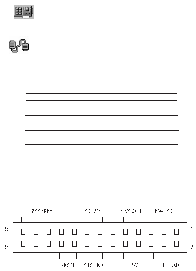
M Front Panel Function Connector
The Mainboard integrates all system front panel functions into
a single on-board connector. These include connections for the
following features:
Function Connector Pin-Out Label
System Reset RESET
Power LED / Keylock PW-LED
Hard Drive Activity LED HD_ LED
Soft-Touch Button Power On/Off PW-BN
External Power Saving Control (optional) EXTSMI
Suspend LED Sus-Led
External speaker Speaker

Glossary
N Flash BIOS
The Mainboard Flash BIOS provides users with more flexibility
in upgrading their mainboards. The flash BIOS can be easily
reprogrammed via software.
O Floppy Drive Header
The Mainboard provides a 34-pin header that supports the
included floppy drive ribbon cable. After connecting the single
end to the on-board “FLOPPY” header, connect the remaining
plugs on the other end of the cable to the corresponding
floppy drives.
P IDE Device Headers
The Mainboard provides two independent bus-mastering PCI
IDE interfaces capable of supporting up to Mode 4 and Ultra
DMA-33/66/100 devices. The system BIOS supports automatic
detection of the IDE device data transfer rate and translation
between different kinds of device modes such as Logical Block
Addressing (LBA), Extended Cylinder Sector Head (ECSH)
translation modes and ATAPI (e.g., CD-ROM) devices on both
IDE interfaces.
The two on-board IDE headers support the provided 80-pin IDE
hard disk ribbon cables. If you install two hard disks and/or
CD-Rom drives onto the same cable, you must configure the
two drives by setting their IDE master/slave jumpers according
to the documentation for those devices.
You may also connect the two hard disk drives so that both
become Masters, using one ribbon cable on the primary IDE
header and one on the secondary IDE header.
Page 47 Mainboard User's Manual

Q WAKEUP-LINK Header
The Mainboard provides on WAKEUP-LINK header (WOL1)
used to connect an add-in Network Interface Card which has
Wakeup capability.
r "CNR" Add-in Board Connector
Communication & Networking Riser (CNR) is a new interface
standard for Networking or modem add-in card.
S CPU Socket
The Mainboard provides a 478-pin CPU Socket for Intel
Pentium 4 processor. The CPU should have a heatsink along
with a fan attached to it to prevent overheat. If a fan is not
present, a fan should be installed prior to turning the system
on.
Mainboard User's ManualPage 48
Glossary
T CPU & System Fan Headers
The recommended heatsink for the processor are those
with 12 Volt three-conductor fan that can be connected to the
fan connector on the mainboard. It provides +12 Volts DC for
the CPU cooling fan as follows:
PIN SIGNAL NAME
1 Ground
2 +12V
3 FAN Speed Detect
CAUTION! Be sure that sufficient air circulation is available across the
processor’s heatsink by regularly checking that your CPU fan is
working. Without sufficient circulation, the processor could overheat
and damage both the processor and the mainboard. You may install
an auxiliary fan if necessary.
The SYSTEM FAN header is provided for optional cooling fans.
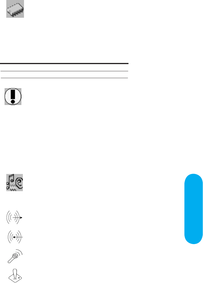
U Game & Audio Connectors
The Mainboard provides Game & Audio connectors.
Line Output
Line Input
Microphone Input
Game Port
Page 49 Mainboard User's Manual

X CD Audio Connector
CD Audio input ( Right, Ground, Ground, Left )
Y Auxiliary Audio Connector
Auxiliary audio input ( Right, Ground, Ground, Left )
Mainboard User's ManualPage 50

Mainboard User's Manual Page 51
CD Driver & Software Installation Guide
Steps :
1. Boot up the Operating System ( Windows 95/98/NT/ME/2000 )
2. Put the CD Disc into the CD-ROM Drive and wait for Autorun
3. Select A845SD and click your Operating System Type
4. Follow the instructions and install suitable drivers
CD Driver & Software
Installation Guide
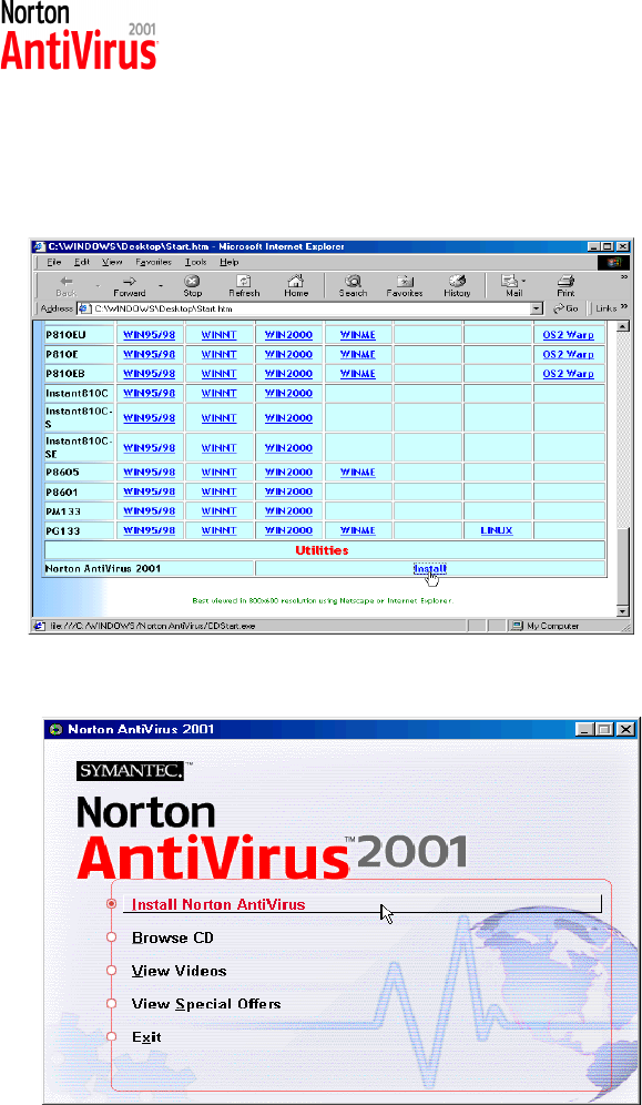
Norton Anti-Virus OEM Version Setup Guide
Step 1 : Load the Driver CD in CDROM and find the Norton
AntiVirus 2001 "Install" Option.
Step 2 : When CD finishes loading, press " Install Norton AntiVirus"
to install the software.
Mainboard User's ManualPage 52
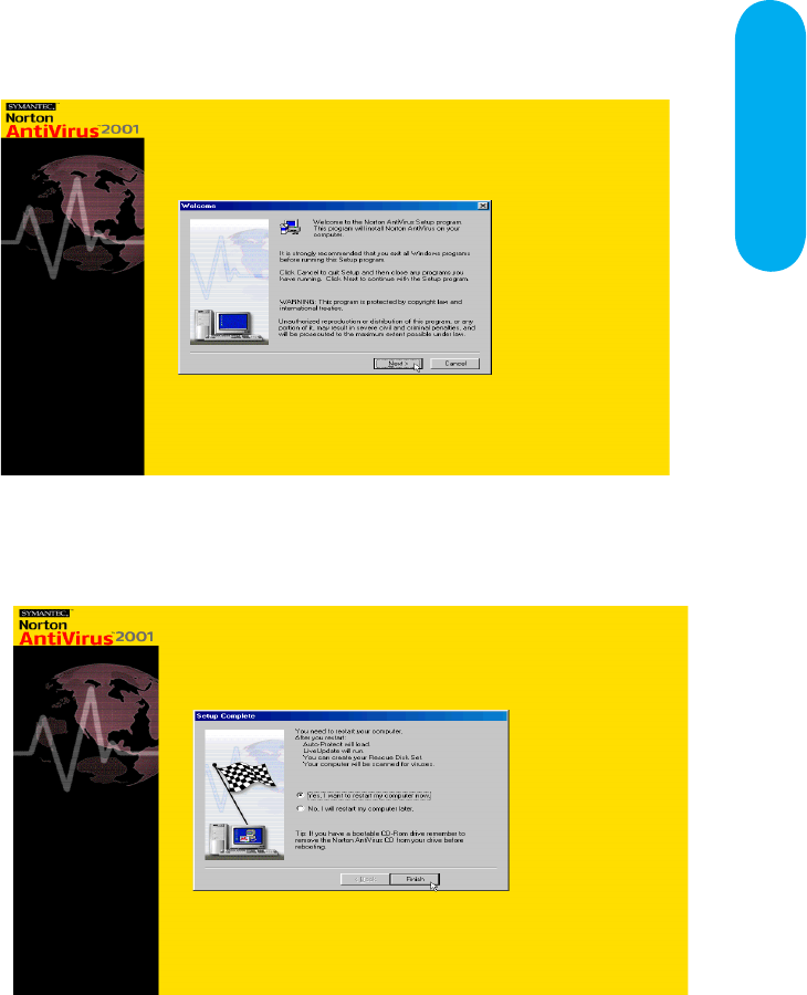
Norton Anti-Virus Setup
Guide
Step 3 : Follow the installation procedures on screen.
Step 4 : Select "Yes" and press "Finish" button to reboot computer.
Page 53 Mainboard User's Manual

Guide
Introduce INSTANT ON function:
INSTANT ON is a Windows 98 ACPI sleep mode function. When
recovering from sleep mode, the system is able, in just a few
seconds, to retrieve the last “state” of the system before it went to
sleep and recover to that state. The “state” is stored in memory
(RAM) before the system goes to sleep. During sleep mode,
your system uses only enough energy to maintain critical
information and system functions, primarily the system state and
the ability to recognize various “wake up” triggers or signals,
respectively.
INSTANT ON function Installation
Please follow the steps to complete the INSTANT ON function
installation.
Mainboard User's ManualPage 54
Power on the computer when memory counting starts,
press <Del>. You will enter BIOS Setup. Select the
item “POWER MANAGEMENT SETUP”, then select S3
(STR) in “ACPI Suspend Type” option. Remember to
save the settings by pressing "ESC" and choose the
“SAVE & EXIT SETUP” option.
The installation of INSTANT ON is completed.
You can use this function in Windows 98.
INSTANT ON GUIDE
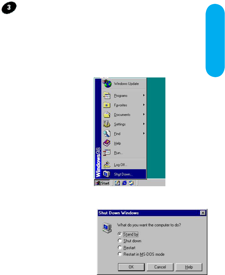
How to put your system into Stand by mode ?
There are two ways :
1. Choose the “Stand by” item in the “Shut Down Windows” area.
B. Choose the “Stand by”
item and Click “OK”
A. Press the “Start”
button and then select
“Shut Down”
Page 55 Mainboard User's Manual
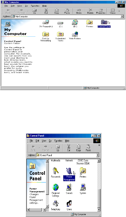
2. Set the system ”power on” button to initiate sleep mode in Win95/98:
A. Double click
“My Computer”
and then
“Control Panel”
B. Double click the “Power
Management” item.
Mainboard User's Manual
Page 56
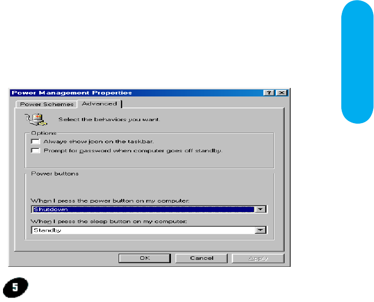
INSTANT ON GUIDE
C. Select the “Advanced” tab and “Standby” mode in
Power Buttons.
Restart your computer to complete setup.
Now when you want to enter sleep mode, just
press the “Power on” button.
How to recover from the sleep mode?
There are four ways to “wake up” the system:
1. Press the “Power On” button.
2. Use the “Keyboard Power On” function.
3. Use the “Modem/Lan Resume" function.
4. Use the “Resume by Alarm” function.
Page 57 Mainboard User's Manual
Notice to INSTANT ON users :
1. ATX power supply requirement
- comply with the ATX 2.01
- provide more than 720 mA 5V Stand-By current
2. SDRAM requirement
- PC133 compliant.
Mainboard User's Manual
Page 58
According to FCC Rule Parts 15.21 and 15.105(b), the following statements should be
placed in a prominent location of the User’s Manual for this device.
NOTE : THE MANUFACTURER IS NOT RESPONSIBLE FOR ANY
RADIO OR TV INTERFERENCE CAUSED BY UNAUTHORIZED
MODIFICATIONS TO THIS EQUIPMENT. SUCH
MODIFICATIONS COULD VOID THE USER’S AUTHORITY TO
OPERATE THE EQUIPMENT.
NOTE :
This equipment has been tested and found to comply with the limits for a Class B
digital device, pursuant to part 15 of the FCC Rules. These limits are designed to
provide reasonable protection against harmful Interference in a residential installation.
This equipment generates, uses and can radiate radio frequency energy and, if not
installed and used in accordance with the instructions, may cause harmful interference
to radio communications. However, there is no guarantee that interference will not
occur in a particular installation. If this equipment does cause harmful interference to
radio or television reception, which can be determined by turning the equipment off
and on, the user is encouraged to try to correct the interference by one or more of the
following measures:
- Reorient or relocate the receiving antenna.
- Increase the separation between the equipment and receiver.
- Connect the equipment into an outlet on a circuit different from that to
which the receiver is connected.
- Consult the dealer or an experienced radio/TV technician for help.