Zida Technologies MB-A845 Tomato User Manual 90 A845S1 00 00 indd
Zida Technologies Ltd. Tomato 90 A845S1 00 00 indd
Contents
- 1. users manual 1
- 2. users manual 2
- 3. users manual 3
- 4. users manual 4
users manual 3

BIOS Setup
Mainboard User's Manual Page 29
UR2 Duplex Mode
This option is not available when UART is set to "Normal". Available options
are Half Duplex and Full Duplex. Default setting is "Half Duplex".
Onboard Parallel Port
Specifies the I/O port address of the onboard parallel port. Available settings
are Disable, 378h, 278h and 3BCh. Default setting is "378h".
Parallel Port Mode
Specifies the onboard parallel port mode. Available options are SPP, EPP,
ECP, ECP+EPP and Normal. Default setting is "SPP".
EPP Mode Select
Specifies the Enhanced Parallel Port specification version number. This option
only appears if the Parallel Port Mode is set to "EPP". The settings are
1.7 or 1.9. Default is N/A because the default setting for the Parallel Port
Mode option is not EPP.
ECP Mode USE DMA
This option only appears if the Parallel Port Mode option is set to ECP. It
assigns a DMA channel to the onboard parallel port. Available settings are
1, 3. Default setting is "3".
PWRON After PWR-Fail
Selects the power-on method after a power function. Options are Off, ON
and Former-Sts.
Game Port Address
Specifies the Onboard Game Port I/O address. Available settings are 201,
209, and Disabled. Default setting is "201".
Midi Port Address
Specifies the I/O address of the MIDI interface on the Onboard Game
Port. Available options are 300h, 330h 290h and Disabled. Default setting
is "330".
Midi Port IRQ
Assigns the IRQ line to the MIDI interface. Available options are 5 and 10.
Default setting is "10". This option is not available if the Onboard Midi Port
is disabled S-232 serial port.
Page 30 Mainboard User's Manual
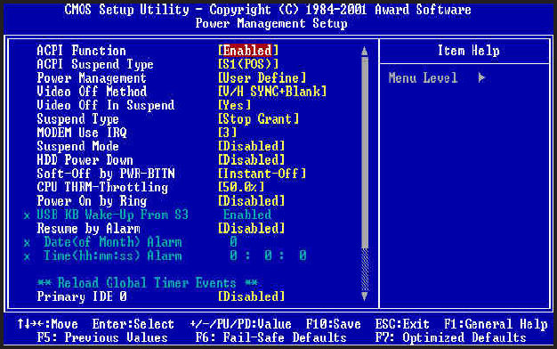
Power Management Setup
ACPI Function
Enabled / Disabled ACPI Function. Default setting is "Disabled".
ACPI Suspend Type
Specifies ACPI Suspend type. Options are : S1(POS), S3(STR) Instant On
function. Default setting is "S1(POS)".
Power Management
Specifies Power Management Mode. Default setting is "User Define".
Video Off Method
Specifies Video off Method. Default setting is V/H SYNC+Blank.
Video Off In Suspend
Specifies Video off in Suspend. Default setting is "Yes".
Suspend Type
Specifies Suspend Type. Default setting is "Stop Grant".
MODEM Use IRQ
Sets Modem use IRQ. Default setting is "3".
Suspend Mode
Specifies Suspend Mode. Default setting is "Disabled".

Mainboard User's Manual Page 31
BIOS Setup
HDD Power Down
Specifies HDD Power Down Mode. Default setting is "Disabled".
Soft Off by PWR-BTTN
Sets Power Down Mode by PWR_BTTN. Default setting is "Instant-off".
CPU THRM-Throttling
Monitor CPU Temperature, slow down CPU Speed.
Power On by Ring
Enabled / Disabled Power on by Ring. Default setting is "Enabled".
USB KB Wake-Up From S3
Enabled / Disabled USB KB Wake-up from S3. Default setting is
"Disabled".
Resume by Alarm
Enabled / Disabled Resume by alarm. Default setting is "Disabled".
Primary IDE0
Enabled / Disabled monitor Primary IDE0 for Green event. Default setting
is "Disabled".
Primary IDE1
Enabled / Disabled monitor Primary IDE1 for Green event. Default setting
is "Disabled".
Secondary IDE0
Enabled / Disabled monitor Secondary IDE0 for Green event. Default
setting is "Disabled".
Secondary IDE1
Enabled / Disabled monitor Secondary IDE1 for Green event. Default
setting is "Disabled".
FDD, COM, LPT Port
Enabled / Disabled monitor FDD, COM, LPT for Green event. Default
setting is "Disabled".
PCI PIRQ [A-D]#
Enabled PCI PIRQIA-DJ#, Monitor PCI PIRQIA-DJ#IRQ Active, Disabled
PCI PIRQIA-DJ# Ignore PCI PIRQIA-DJ# IRQ Active. Default setting
is "Disabled".
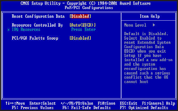
PnP/PCI Configurations
Reset Configuration Data
Enabled / Disabled Reset configuration Data. Default setting is
"Disabled".
Resources Controlled By
Sets the allocation of PCI resources. Available options are Manual and
Auto(ESCD). Default setting is "Auto"(ESCD). BIOS automatically
assigns resources.
IRQ Resources
When resources are controlled manually, assign each system inter-
rupt a type, depending on the type of device using the interrupt.
PCI/VGA Palette Snoop
Enabled / Disabled PCI / VGA Palette Snoop, sets "Enabled" for
having Video card on ISA Bus and VGA card on PCI Base, sets
"Disabled" for VGA card only.
Mainboard User's ManualPage 32
BIOS Setup
Page 33 Mainboard User's Manual
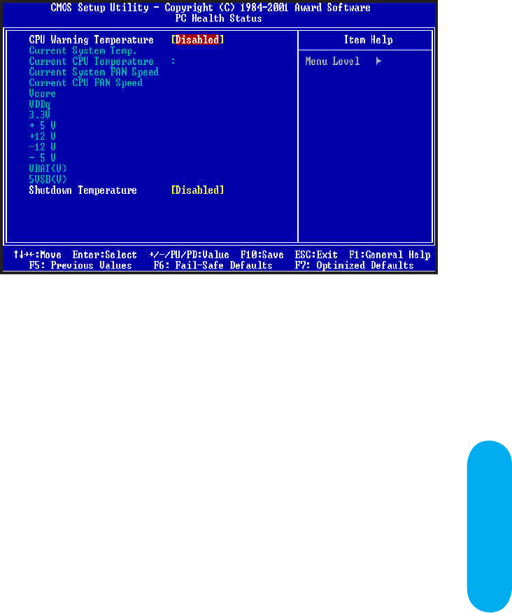
CPU Warning Temperature
Specifies CPU warning temperature value. Available options are 50°C/122°F,
53°C/127°F, 56°C/133°F, 60°C/140°F, 63°C/145°F, 66°C/151°F, 70°C/158°F
and Disabled. Default setting is "Disabled".
Current System Temp.
Current CPU Temperature
Display System and CPU temperatures.
Current System Fan Speed
Current CPU Fan Speed
Display Fan Speed status.
Vcore/VDDq/3.3V/+5V/+12V/-12V/-5V/VBAT(V)/5VSB(V)
Display System's Voltage status.
Shutdown Temperature
This function will only be effective for operating systems that support ACPI
Function. Specifies Shutdown Temperature Value. Available options are
60°C/140°F, 65°C/149°F, 70°C/158°F, 75°C/167°F and Disabled. Default
setting is "Default".
PC Health Status
Page 34 Mainboard User's Manual
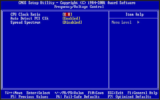
CPU Clock Ratio
Select CPU’s core/bus frequency ratio. This setting has no effect
on processors with frequency ratio locked. Available settings are
between X8 to X24 of the CPU BUS Speed. Default setting is
"X8" (Safe).
Auto Detect PCI Clk
Enabled / Disabled Auto detect PCI CLOCK. Default setting is
"Enabled".
Spread Spectrum
This option turns on/off the clock generator’s Spread Spectrum
feature to reduce Electromagnetic Interference (EMI) generated by
high speed clock signals. Default setting is "Disabled".
Frequency / Voltage Control
BIOS Setup
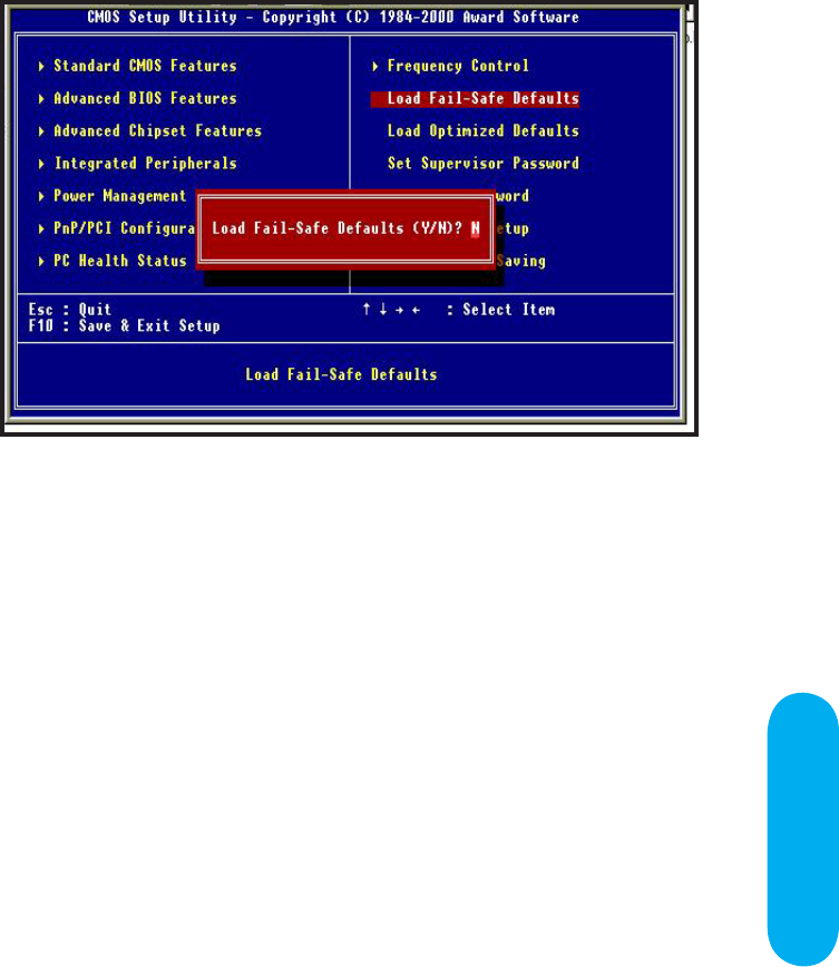
Fail-safe defaults contain the most appropriate values of the system
parameters that allow minimum system performance.
Load Fail-safe Defaults
Mainboard User's Manual Page 35
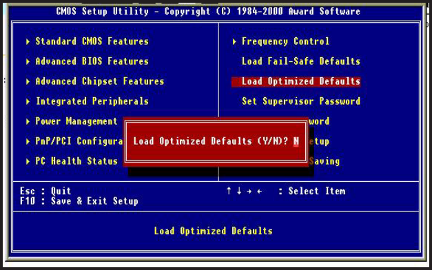
Load Optimized Defaults
Selecting this field loads the factory defaults for BIOS and Chipset
Features which the system automatically detects.
Page 36 Mainboard User's Manual
BIOS Setup
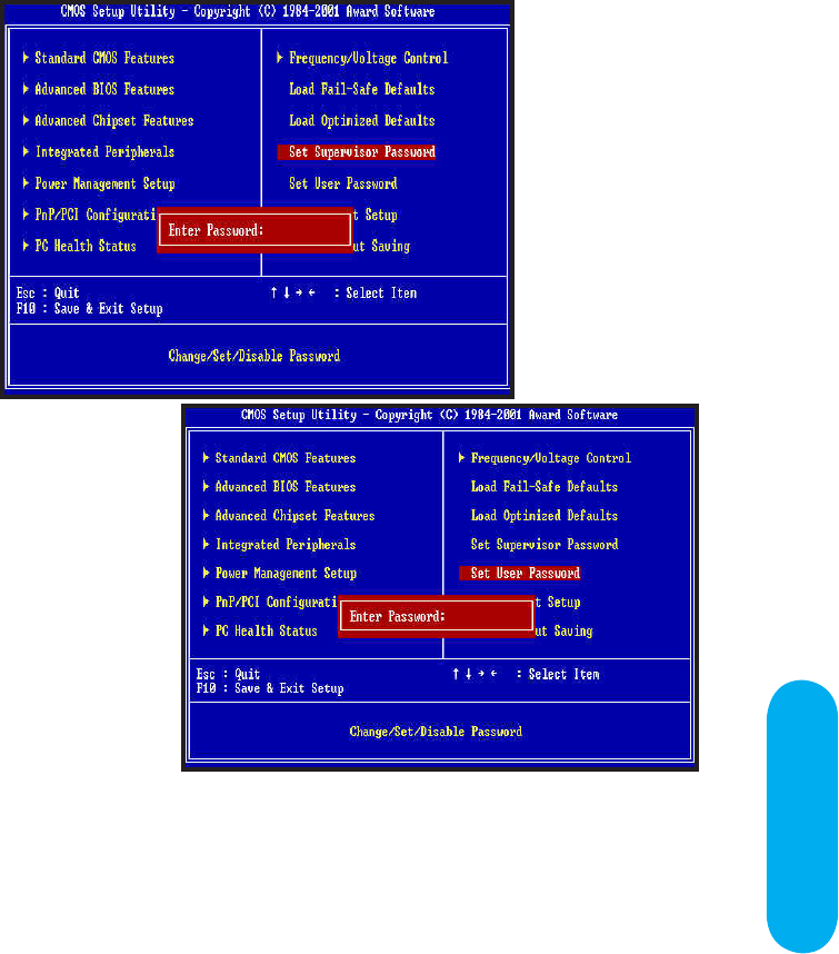
Set Supervisor / User password
When you select this function, the following message will appear at
the center of the screen to assist you in creating a password.
Type the password, up to eight characters and press<Enter>. The
new password will clear the previously entered password from
CMOS Memory, you will be asked to confirm the Password. Type
the password again and press <Enter>, you may also press <ESC>
to about the selection and not enter a password.
Mainboard User's Manual Page 37
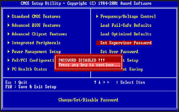
To disable password, just press <Enter> when you are prompted
to enter password. A Message <<PASSWORD DISABLED!!!>> will
appear to confirm the password being disabled. Once the password
is disabled, the system will boot and you can enter setup freely.
If you select "System" at "Security Option" in BIOS Features Setup
Menu, you will be prompted for the password every time. If you
select "Setup" at "Security option" in BIOS Features Setup Menu,
you will be prompted only when you try to enter Setup.
Page 38 Mainboard User's Manual
BIOS Setup
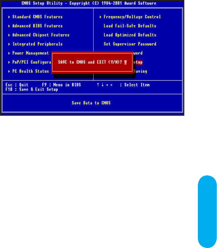
Type "Y" will quit the Setup Utility and Save the user setup value
to RTC CMOS.
Type "N" will return to Setup Utility.
Save & Exit Setup
Mainboard User's Manual Page 39
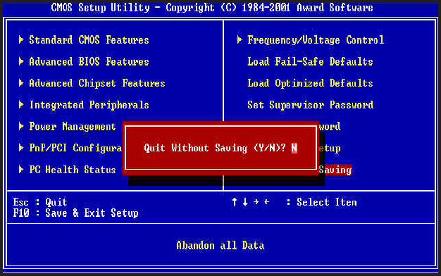
Type "Y" will quit the Setup Utility and Without Saving the User
setup Value.
Type "N" will return to Setup Utility.
Exit Without Saving
Page 40 Mainboard User's Manual

Glossary

A PS/2 Mouse & Keyboard Connector
The Mainboard provides two on-board PS/2 connectors, one for
the keyboard, and one for the mouse. PS/2 devices all have
a standard 6-pin round shape connector. If you are already
using a PS/2 mouse or keyboard, simply plug them into the
corresponding connector. No jumper settings are necessary.
B ATX Power Supply Connectors
The Mainboard provides 20-pin ATX power supply connector,
which incorporates standard +5V and +12V, 3.3V and soft-on/off
signals. With a power supply that supports remote power on/off,
the mainboard can turn off the system power through software
control, such as the shutdown command in the Windows 95 /
Windows 98 Start Menu. The BIOS system will turn the system
power off when it receives the proper APM / ACPI command
from the OS. APM / ACPI must be enabled in the BIOS and
OS systems in order to set the soft-off feature working properly.
This Pentium 4 Mainboard also provides a 4-pin power supply
connector, which incorporates additional +12V power for the
CPU power circuitry.
20-pin ATX Power Supply Connector
Pin Signal Name Pin Signal Name
1 +3.3V 11 +3.3V
2 +3.3V 12 -12V
3 Ground 13 Ground
4 +5V 14 PW_ON
5 Ground 15 Ground
6 +5V 16 Ground
7 Ground 17 Ground
8 PWRGOOD 18 -5V
9 +5VSB 19 +5V
10 +12V 20 +5V
Glossary
Page 42 Mainboard User's Manual