Zida Technologies MB-A845 Tomato User Manual 90 A845S1 00 00 indd
Zida Technologies Ltd. Tomato 90 A845S1 00 00 indd
UserManual.wiki
>
Zida Technologies
>
MB-A845 User Manual
>
users manual 3
Contents
1.
users manual 1
2.
users manual 2
3.
users manual 3
4.
users manual 4
users manual 3
Navigation menu
Upload a User Manual
Namespaces
Wiki Guide
HTML
PDF
Info
Views
User Manual
Discussion / Help
Navigation

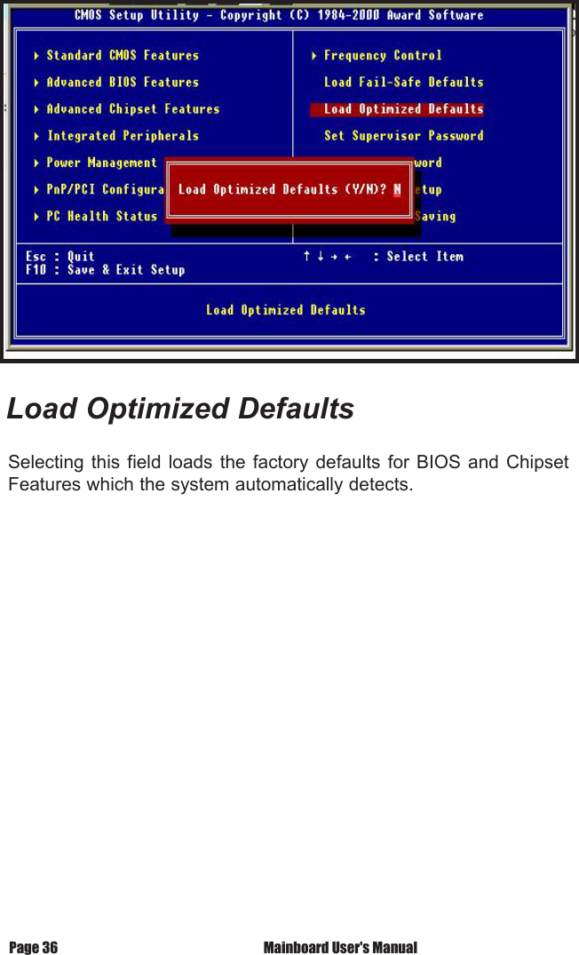
![Mainboard User's Manual Page 31BIOS SetupHDD Power DownSpecifies HDD Power Down Mode. Default setting is "Disabled".Soft Off by PWR-BTTNSets Power Down Mode by PWR_BTTN. Default setting is "Instant-off".CPU THRM-ThrottlingMonitor CPU Temperature, slow down CPU Speed.Power On by RingEnabled / Disabled Power on by Ring. Default setting is "Enabled".USB KB Wake-Up From S3Enabled / Disabled USB KB Wake-up from S3. Default setting is "Disabled".Resume by AlarmEnabled / Disabled Resume by alarm. Default setting is "Disabled".Primary IDE0Enabled / Disabled monitor Primary IDE0 for Green event. Default setting is "Disabled".Primary IDE1Enabled / Disabled monitor Primary IDE1 for Green event. Default setting is "Disabled".Secondary IDE0Enabled / Disabled monitor Secondary IDE0 for Green event. Default setting is "Disabled".Secondary IDE1Enabled / Disabled monitor Secondary IDE1 for Green event. Default setting is "Disabled".FDD, COM, LPT PortEnabled / Disabled monitor FDD, COM, LPT for Green event. Default setting is "Disabled".PCI PIRQ [A-D]#Enabled PCI PIRQIA-DJ#, Monitor PCI PIRQIA-DJ#IRQ Active, Disabled PCI PIRQIA-DJ# Ignore PCI PIRQIA-DJ# IRQ Active. Default setting is "Disabled".](https://usermanual.wiki/Zida-Technologies/MB-A845.users-manual-3/User-Guide-190358-Page-3.png)