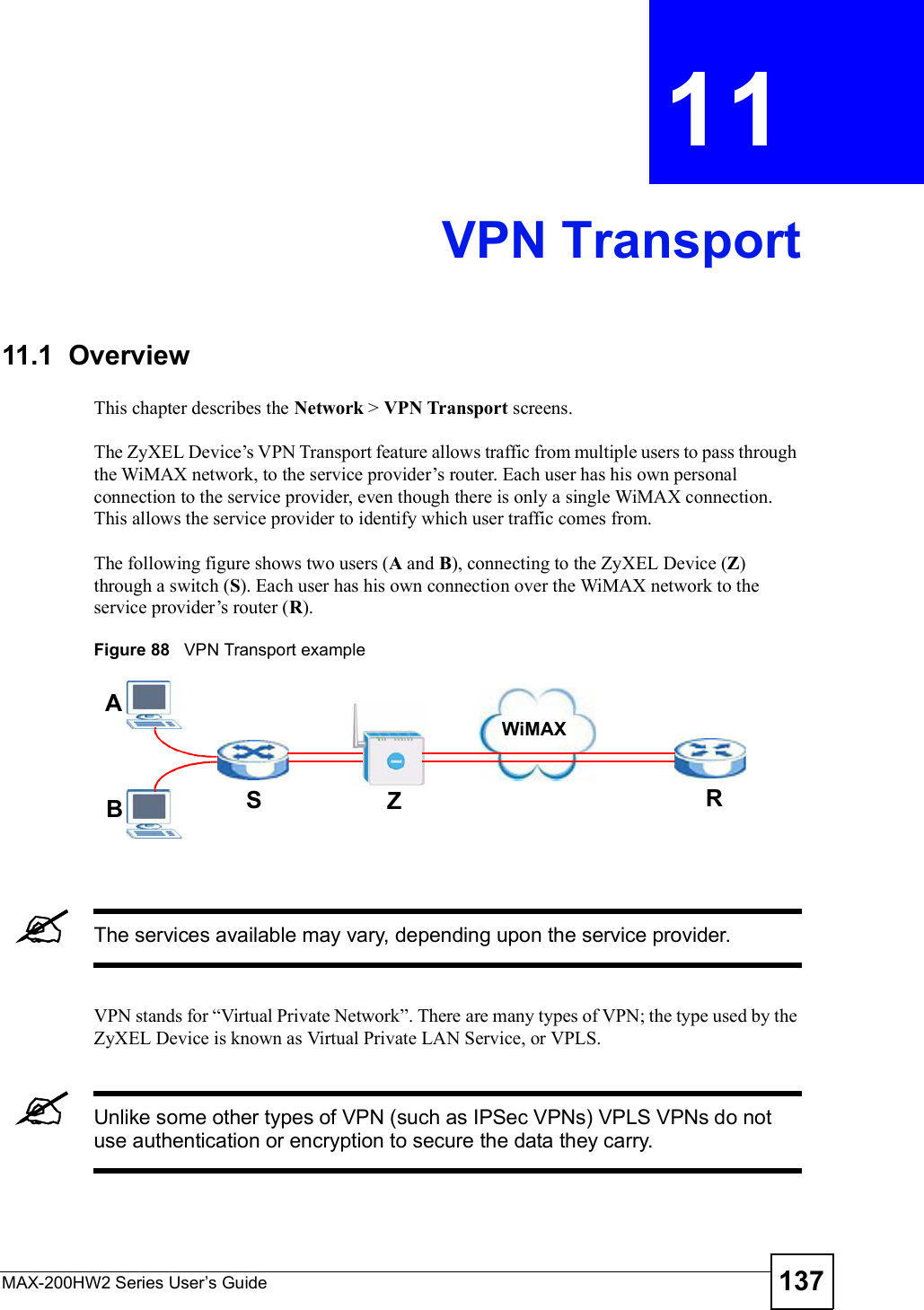
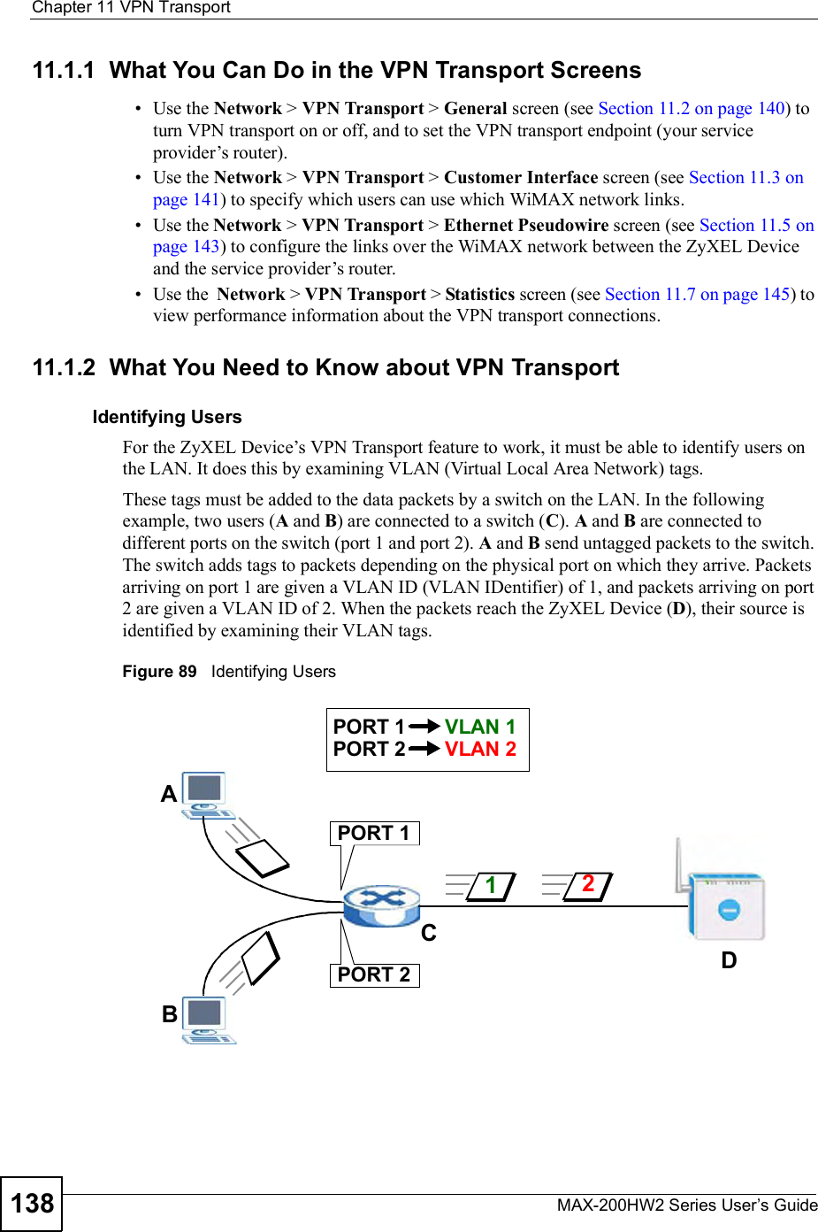
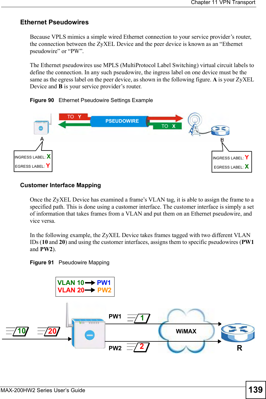
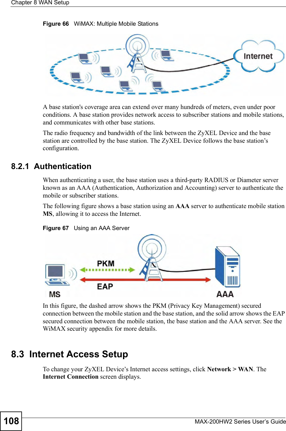
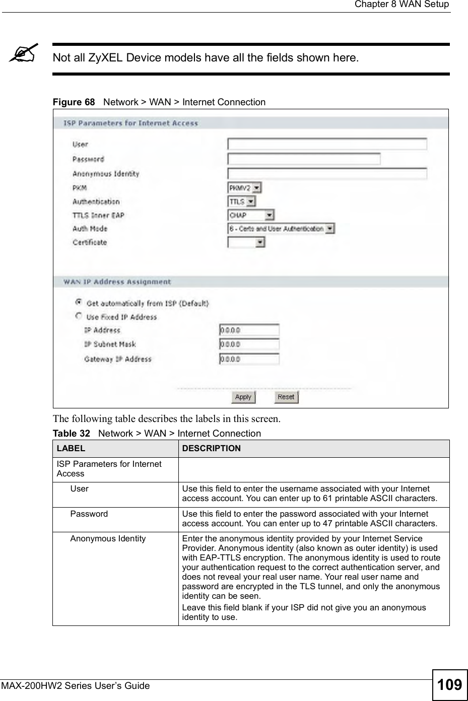
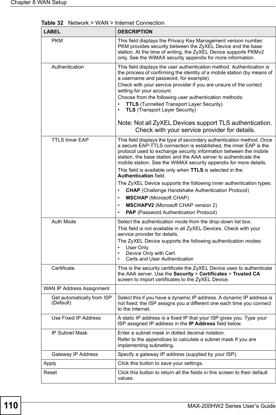
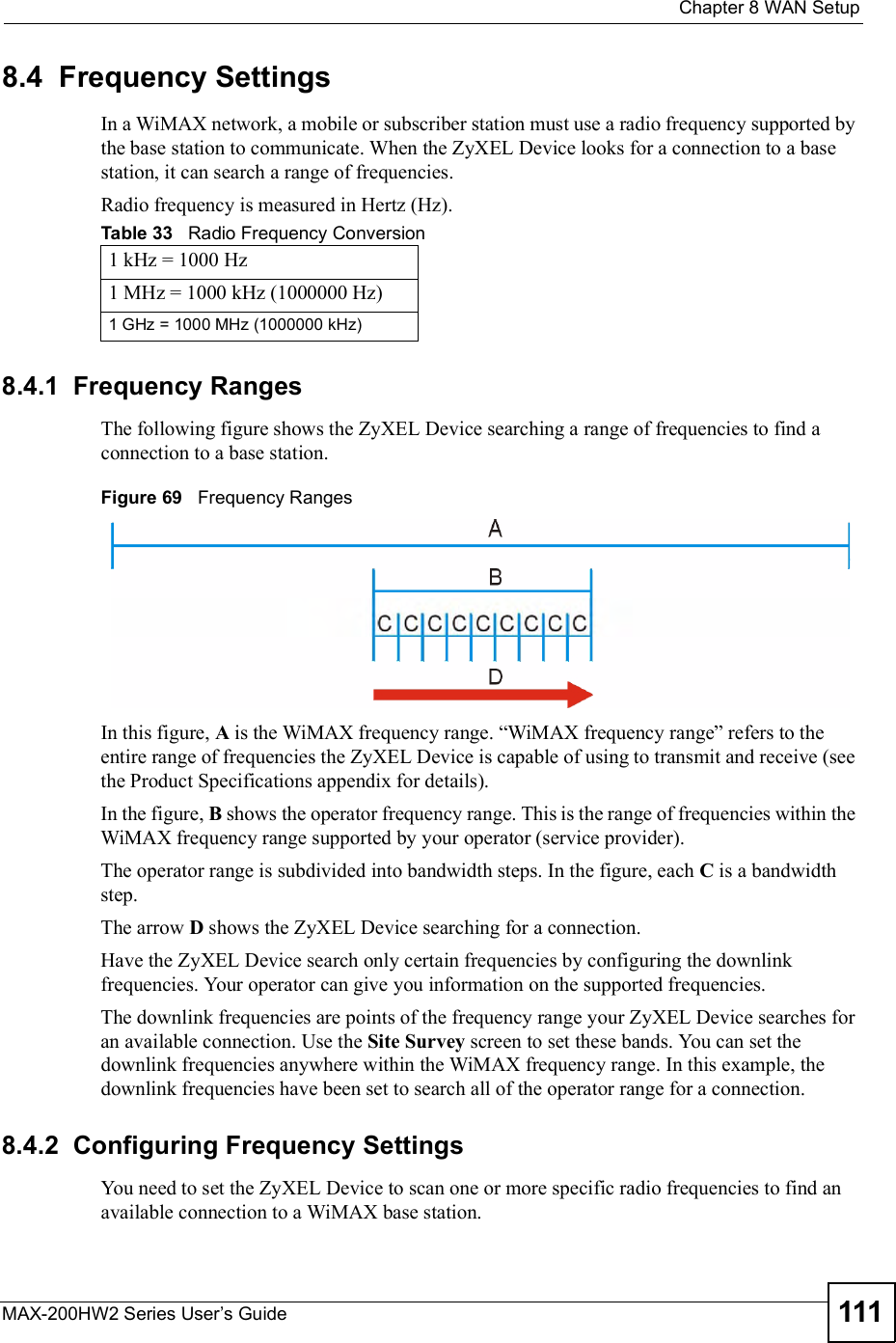
ZyXEL Communications MAX200HW2 WiMAX Router User Manual UserMan I88MAX200HW2 revised
ZyXEL Communications Corporation WiMAX Router UserMan I88MAX200HW2 revised
Contents
- 1. User manual revised 1
- 2. User manual revised 2
- 3. User manual revised 3
- 4. User manal revised 3
User manual revised 1
![Document ConventionsMAX-200HW2 Series User s Guide4Document ConventionsWarnings and NotesThese are how warnings and notes are shown in this User!s Guide. Warnings tell you about things that could harm you or your ZyXEL Device.Notes tell you other important information (for example, other things you may need to configure or helpful tips) or recommendations.Syntax Conventions The ZyXEL MAX-200HW2 Series may be referred to as the "ZyXEL Device#, the "device#, the "system# or the "product# in this User!s Guide. Product labels, screen names, field labels and field choices are all in bold font. A key stroke is denoted by square brackets and uppercase text, for example, [ENTER] means the "enter# or "return# key on your keyboard. "Enter# means for you to type one or more characters and then press the [ENTER] key. "Select# or "choose# means for you to use one of the predefined choices. A right angle bracket ( > ) within a screen name denotes a mouse click. For example, Maintenance > Log > Log Setting means you first click Maintenance in the navigation panel, then the Log sub menu and finally the Log Setting tab to get to that screen. Units of measurement may denote the "metric# value or the "scientific# value. For example, "k# for kilo may denote "1000# or "1024#, "M# for mega may denote "1000000# or "1048576# and so on. "e.g.,# is a shorthand for "for instance#, and "i.e.,# means "that is# or "in other words#.Icons Used in FiguresFigures in this User!s Guide may use the following generic icons. The ZyXEL Device icon is not an exact representation of your ZyXEL Device.](https://usermanual.wiki/ZyXEL-Communications/MAX200HW2.User-manual-revised-1/User-Guide-913209-Page-2.png)
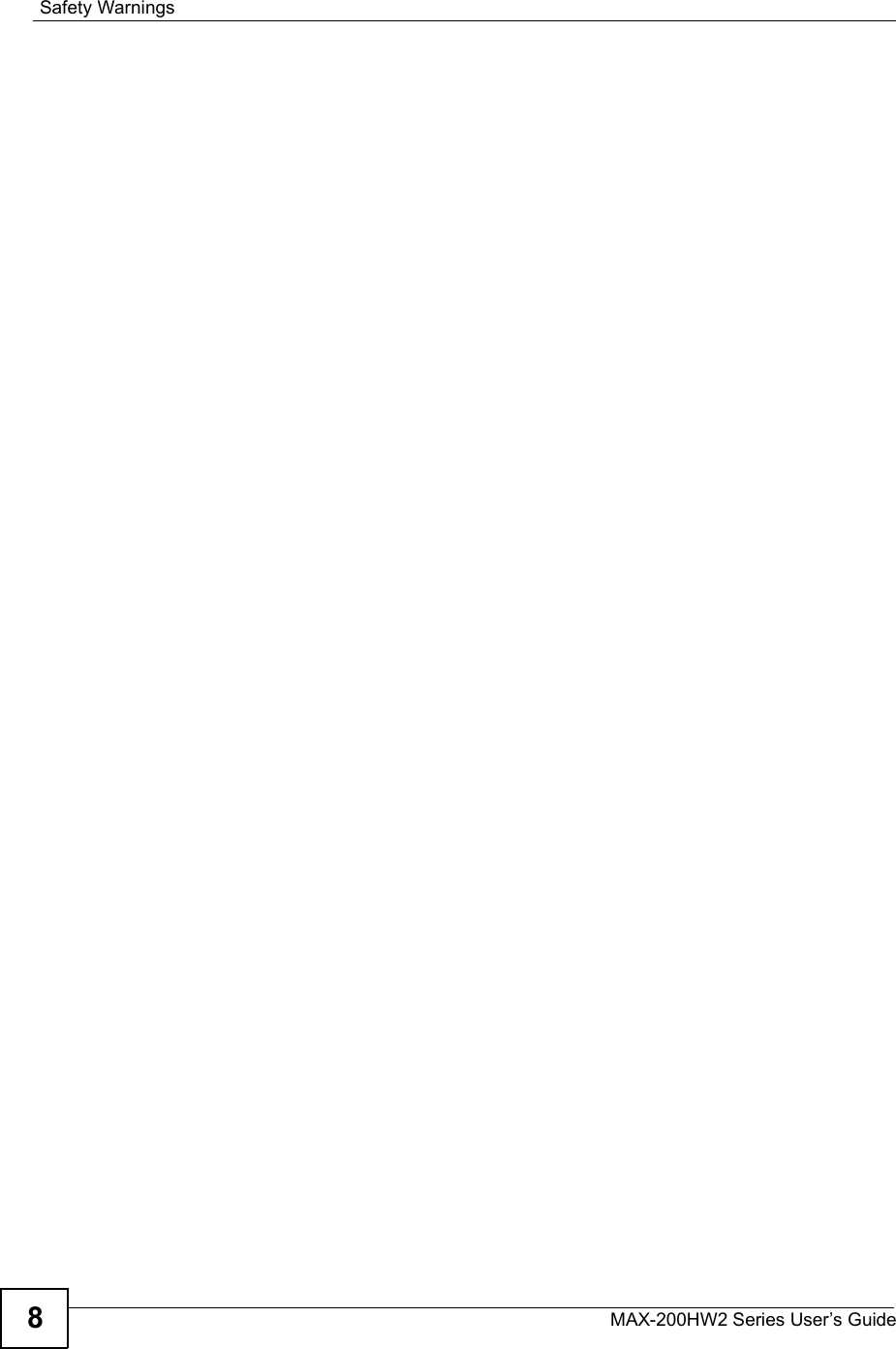


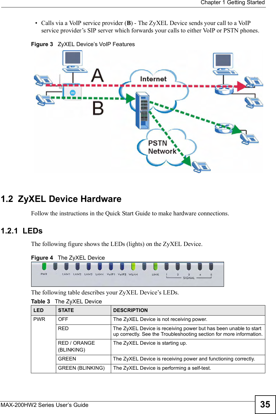


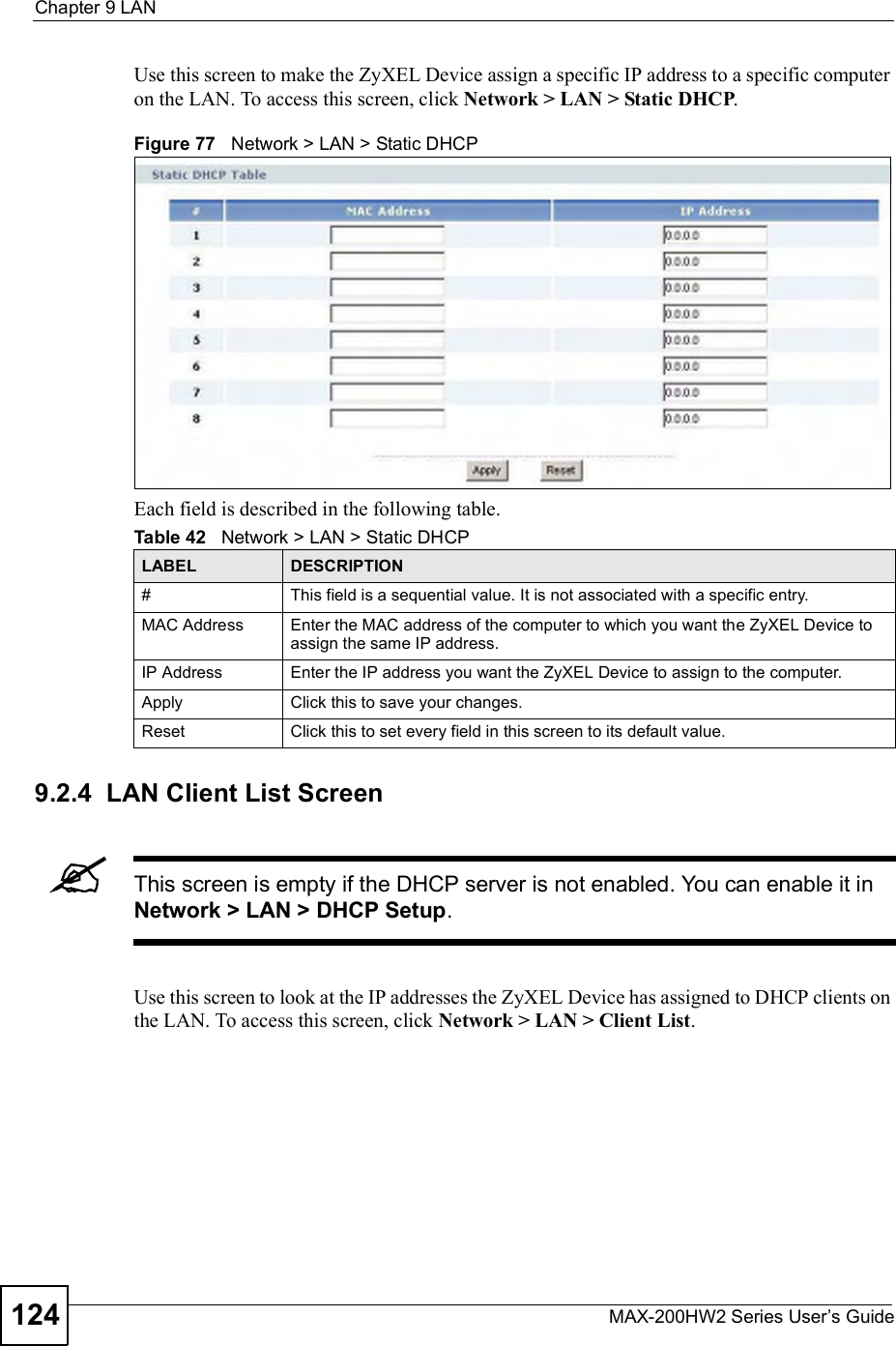
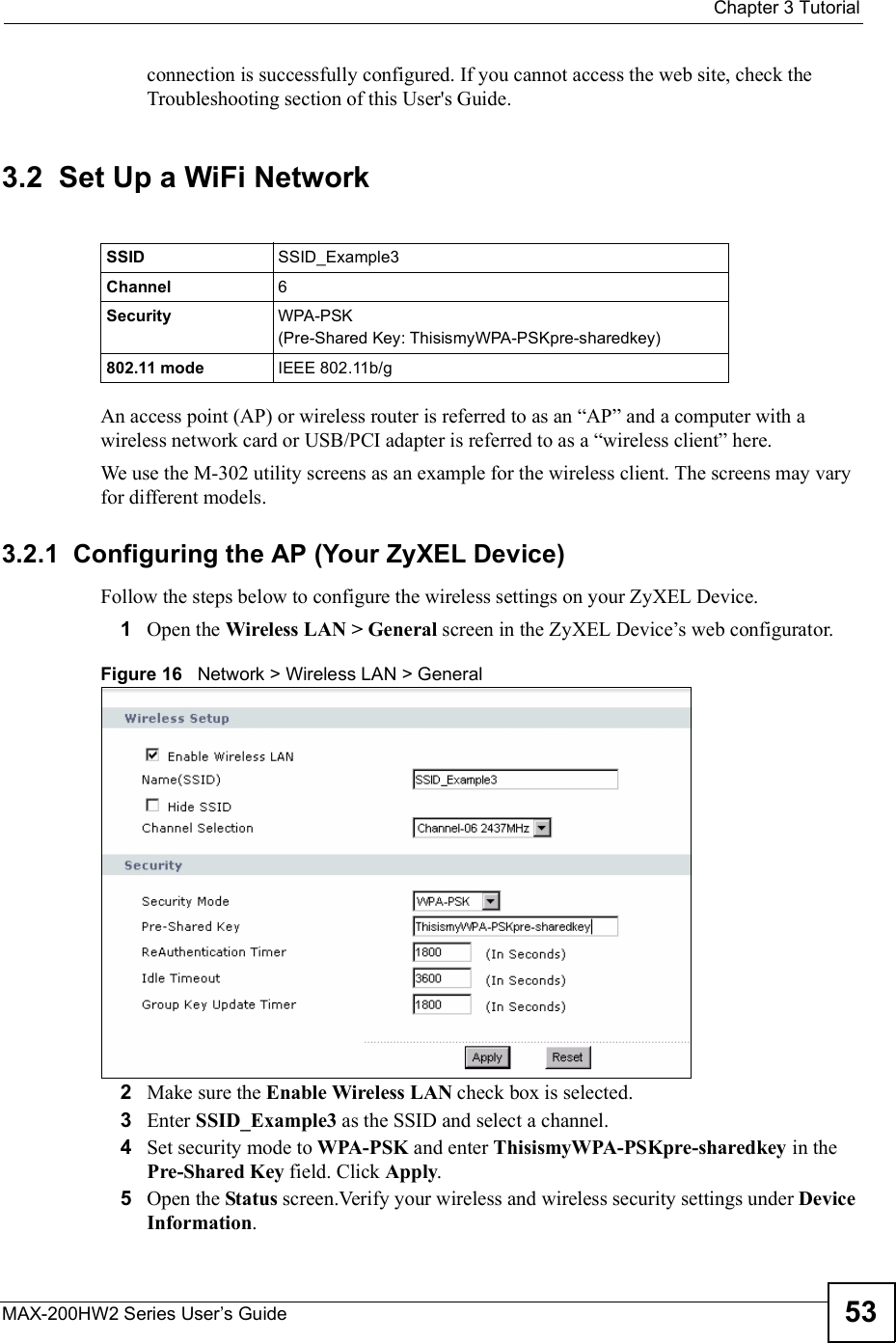
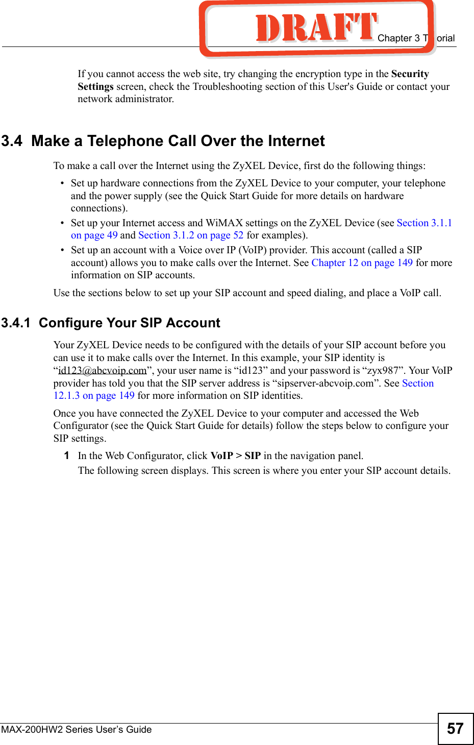
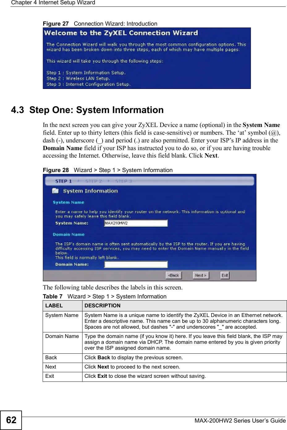
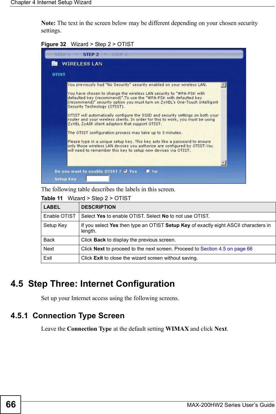
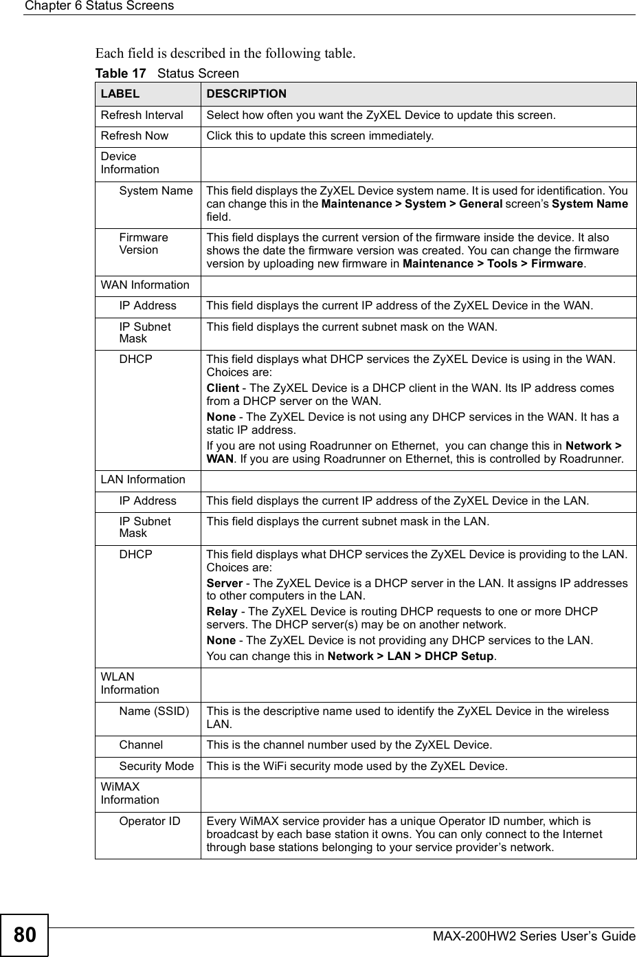
![Chapter 3TutorialMAX-200HW2 Series User s Guide528Click Apply. Your Internet access settings are saved to the ZyXEL Device, and are used automatically each time you connect to the Internet.3.1.2 Configure WiMAX SettingsThe WiMAX Frequency screen allows you to specify a set of frequencies to search for a connection to a base station. Before you start, you need information from your ISP about the supported frequencies. In this example, your ISP has told you that the supported WiMAX frequencies are at 2.55 and 2.56 Gigahertz (GHz). See Section 8.4 on page 111 for more information on radio frequencies.Follow the steps below to configure your frequency settings.1Click Network > WAN > WiMAX Frequency to open the screen shown next.Figure 15 Tutorial: WiMAX Frequency Setup2Enter the frequency settings your ISP gave you in the DL Frequency fields. Note that these fields are in kilohertz (kHz).2.55 GHz is equal to 2550000 kHz, so enter 2550000 in the DL Frequency [1] field.2.56 GHz is equal to 2560000 kHZ, so enter 2560000 in the DL Frequency [2] field.3Click Apply to save your settings. The ZyXEL Device scans for an available wireless connection at the DL Frequency [1] setting (2.55 GHz) and, if it does not find an available connection, searches at the DL Frequency [2] setting (2.56 GHz). When it finds an available connection, the fields in this screen will be automatically set to use that frequency.For an example of using the WiMAX Frequency screen to configure more frequencies, see Section 8.4.2.1 on page 113.4Look at the LEDs on your ZyXEL Device. When the ZyXEL Device successfully connects to a base station, the LINK LED shines green steadily. The SIGNAL 1 ~ 5LEDs indicate the signal strength, with SIGNAL 5 showing a very strong signal and SIGNAL 1 showing a very weak signal.5Open your Internet browser and enter http://www.zyxel.com or the URL of any other web site in the address bar. If you are able to access the web site, your wireless](https://usermanual.wiki/ZyXEL-Communications/MAX200HW2.User-manual-revised-1/User-Guide-913209-Page-50.png)
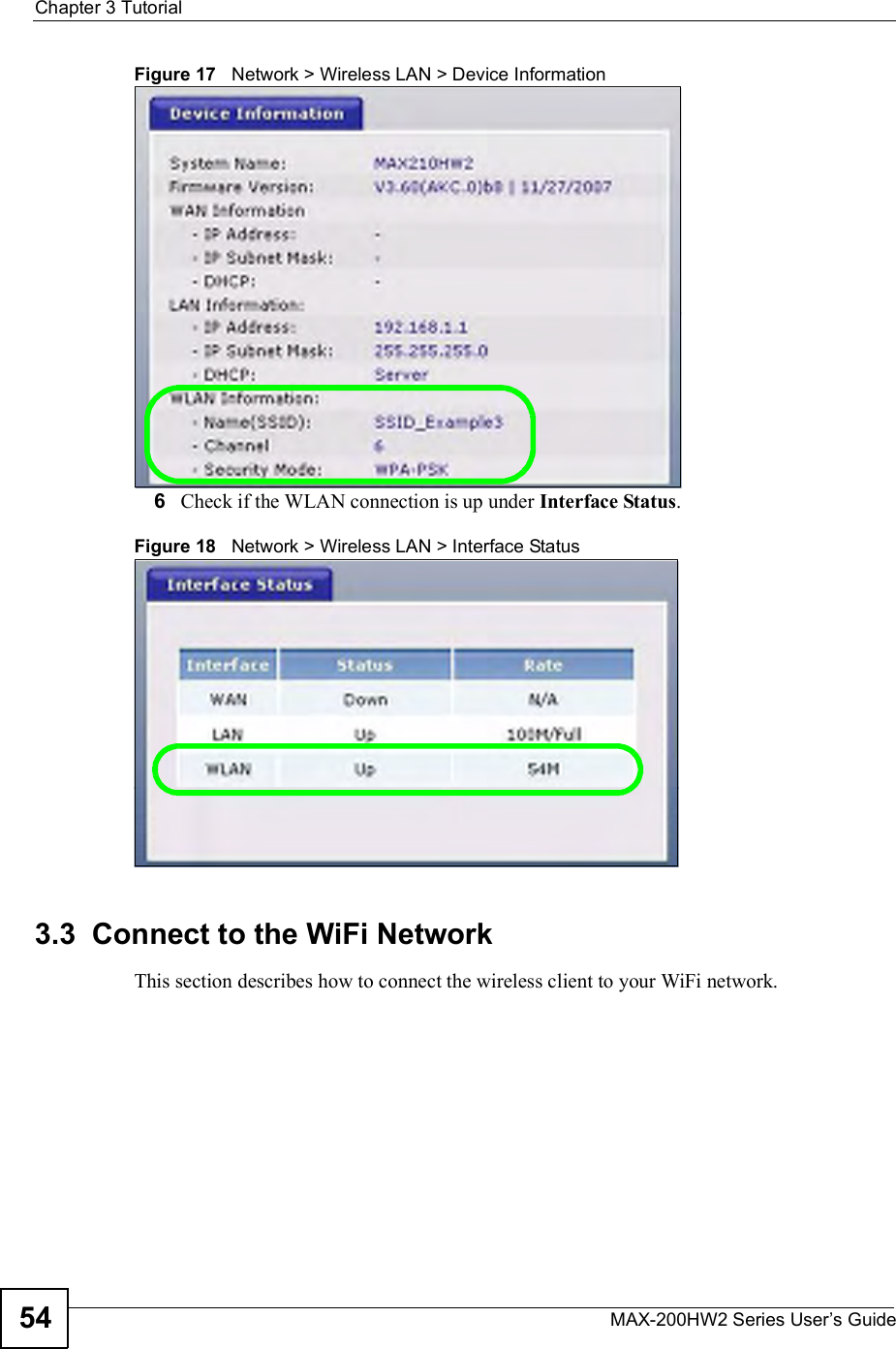


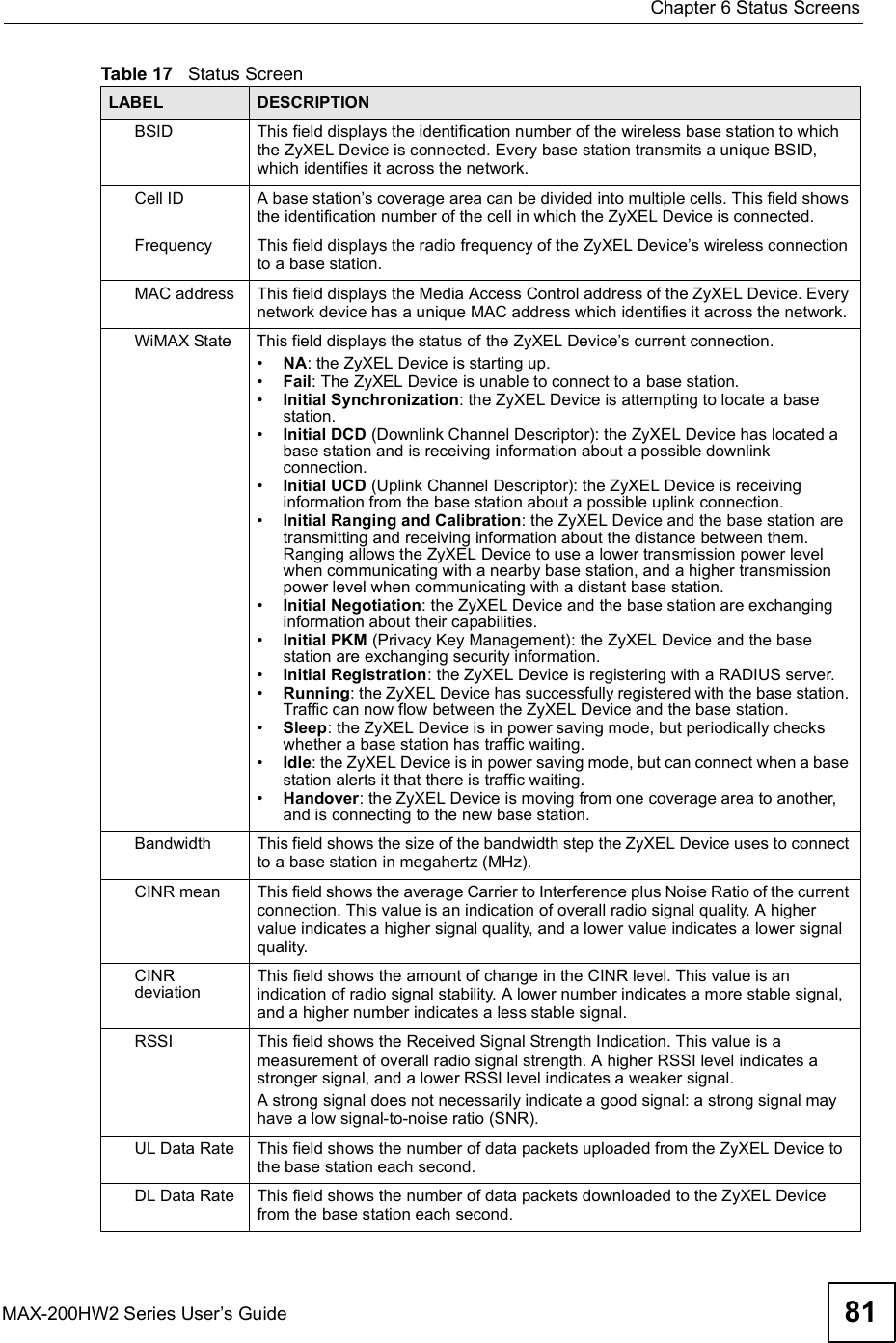
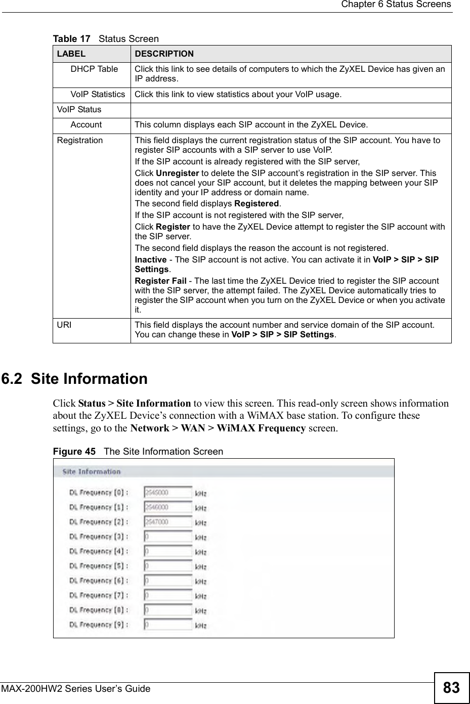
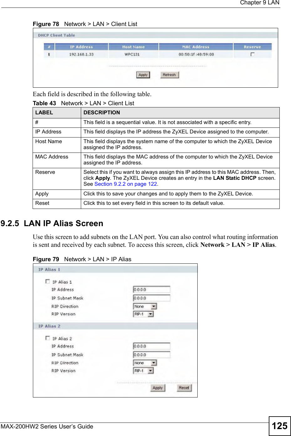
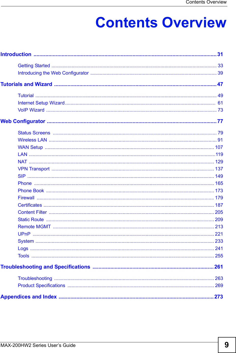
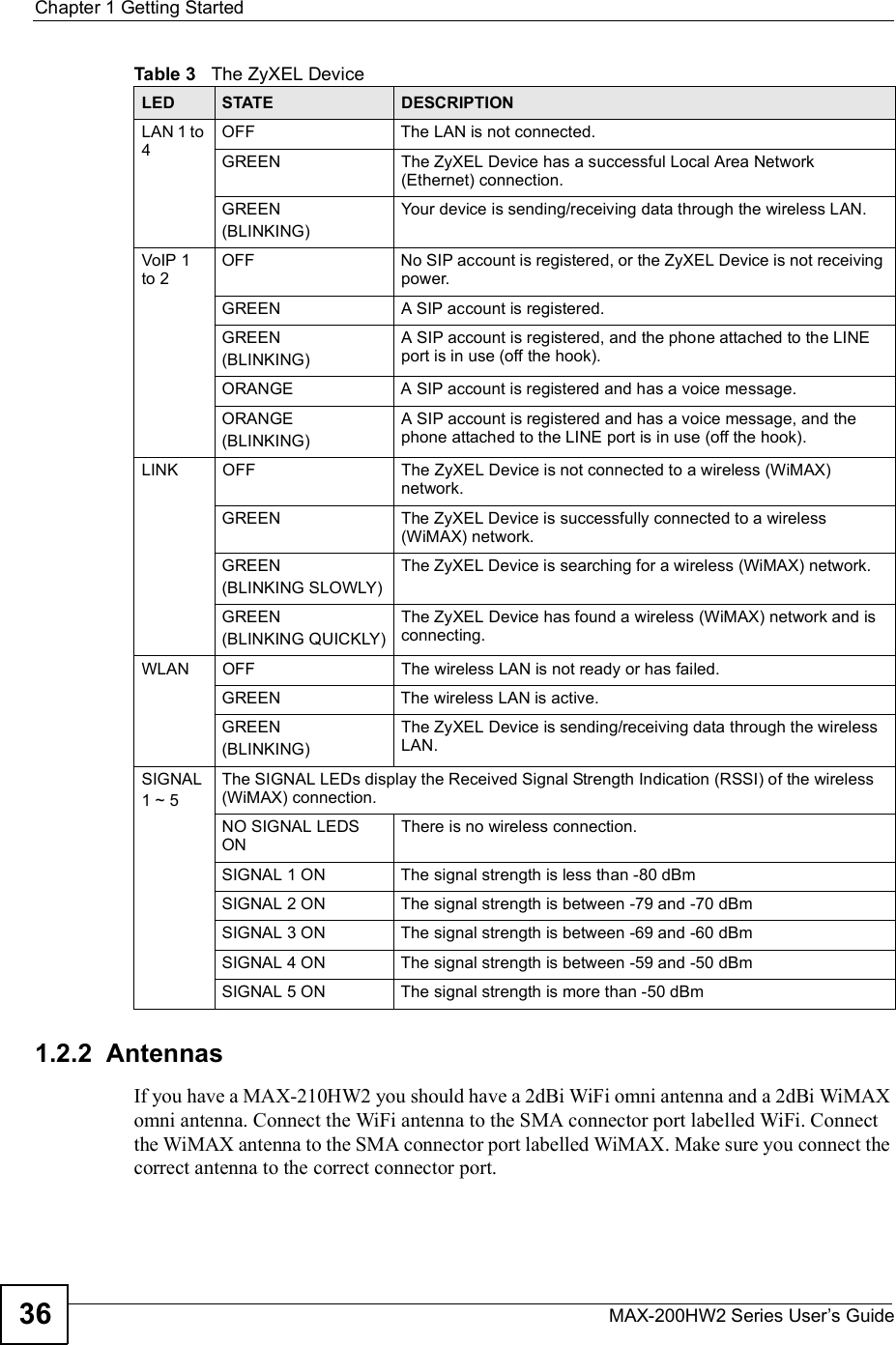
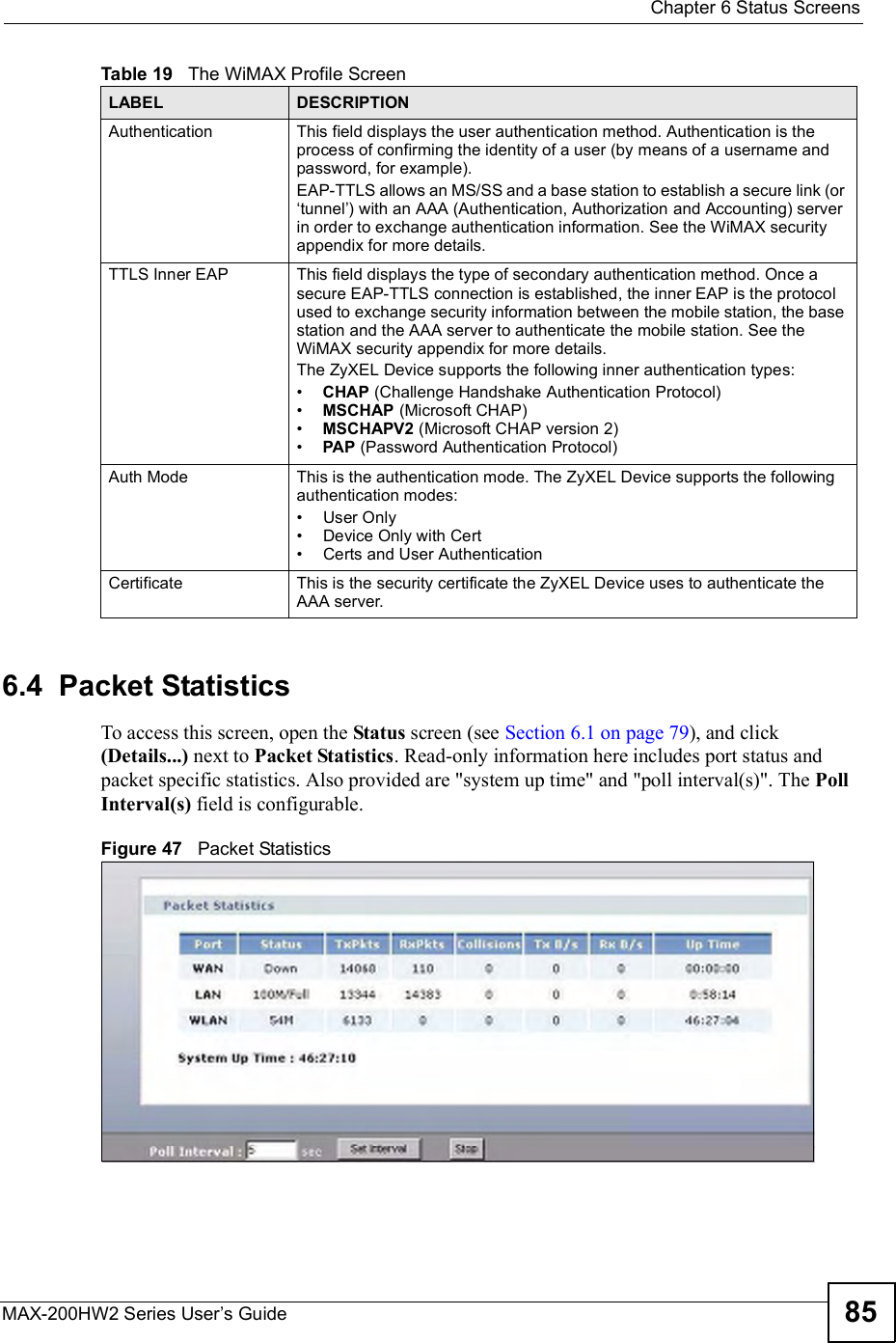
![Chapter 6Status ScreensMAX-200HW2 Series User s Guide84The following table describes the labels in this screen. 6.3 ProfileClick Status > Profile to view this screen. This read-only screen displays information about the security settings you are using. To configure these settings, go to the Network > WAN > Internet Connection screen.Not all ZyXEL Device models have all the fields shown here.Figure 46 The WiMAX Profile Screen The following table describes the labels in this screen.Table 18 The Site Information ScreenLABEL DESCRIPTIONSite InformationDL Frequency[0] ~ [9]These fields show the downlink frequency settings in kilohertz (kHz). These settings determine how the ZyXEL Device searches for an available wireless connection. See Section 8.4 on page 111 for more information.Table 19 The WiMAX Profile ScreenLABEL DESCRIPTIONProfileUserThis is the username for your Internet access account. PasswordThis is the password for your Internet access account. The password displays as a row of asterisks.Anonymous IdentityThis is the anonymous identity provided by your Internet Service Provider. Anonymous identity (also known as outer identity) is used with EAP-TTLS encryption.PKMThis field displays the Privacy Key Management version number. PKM provides security between the ZyXEL Device and the base station. See the WiMAX security appendix for more information.](https://usermanual.wiki/ZyXEL-Communications/MAX200HW2.User-manual-revised-1/User-Guide-913209-Page-82.png)
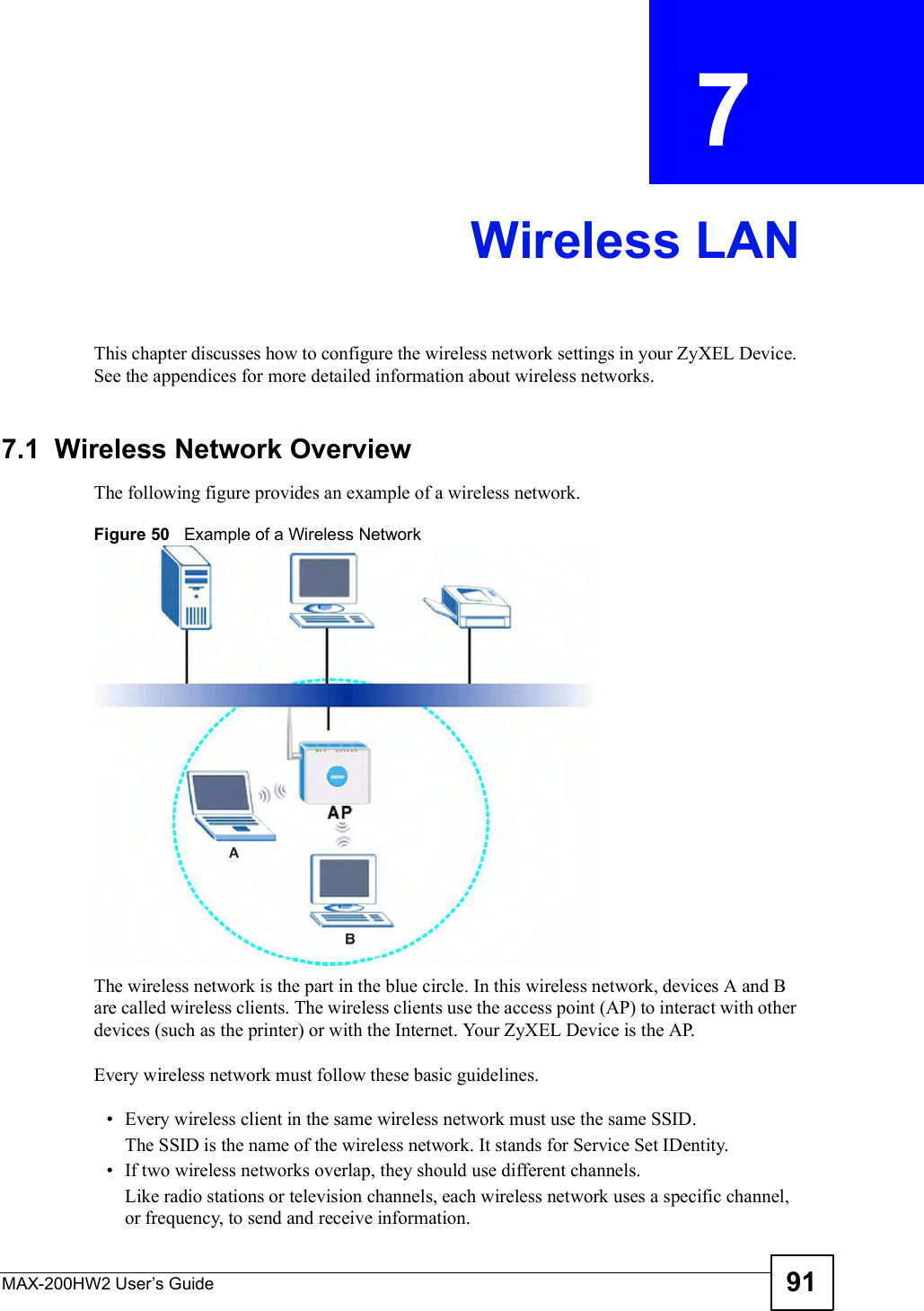
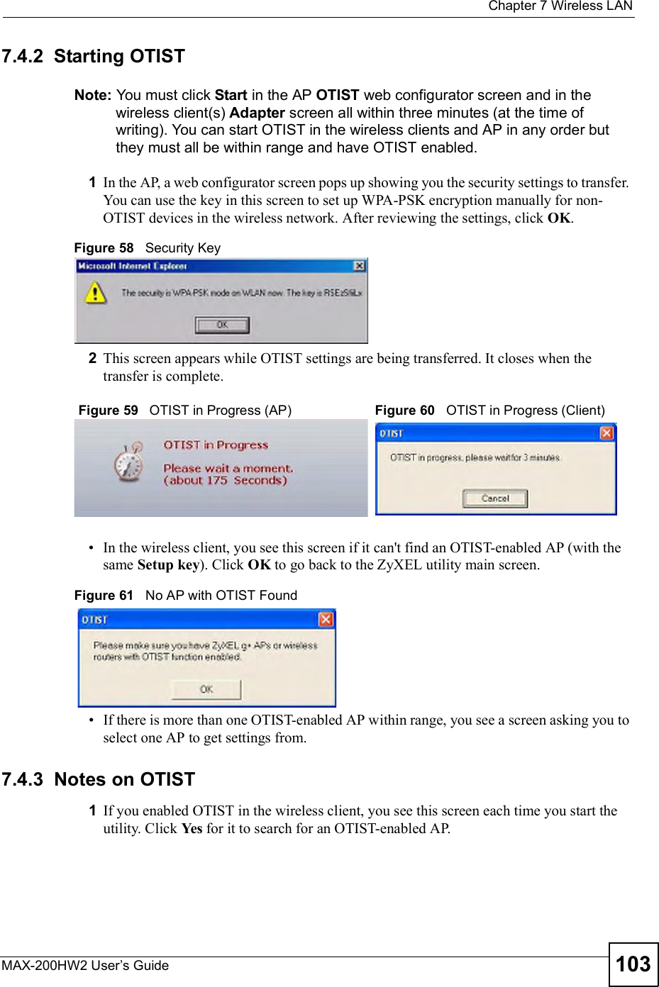
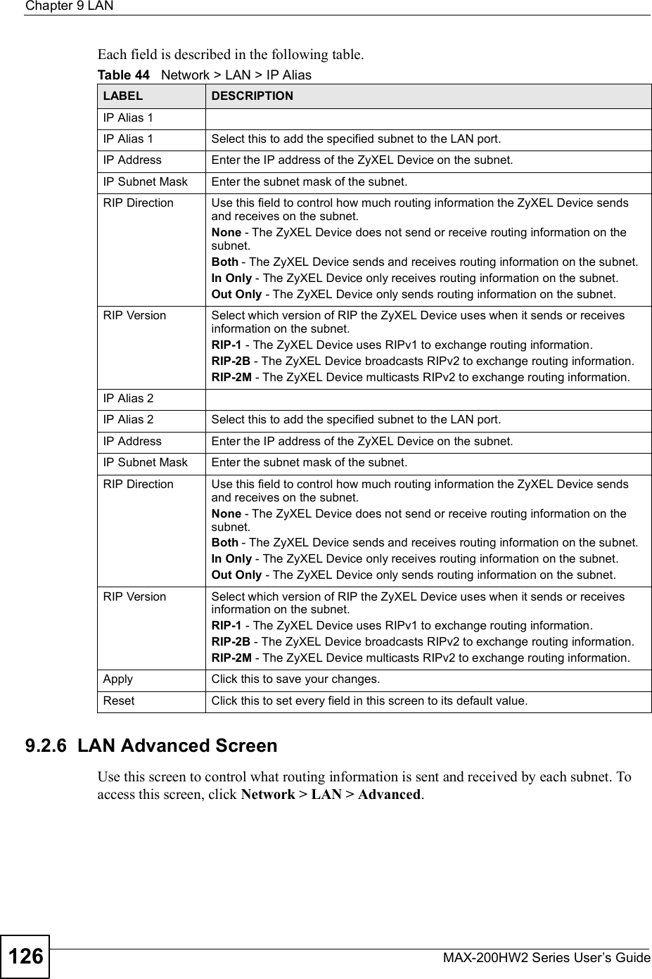
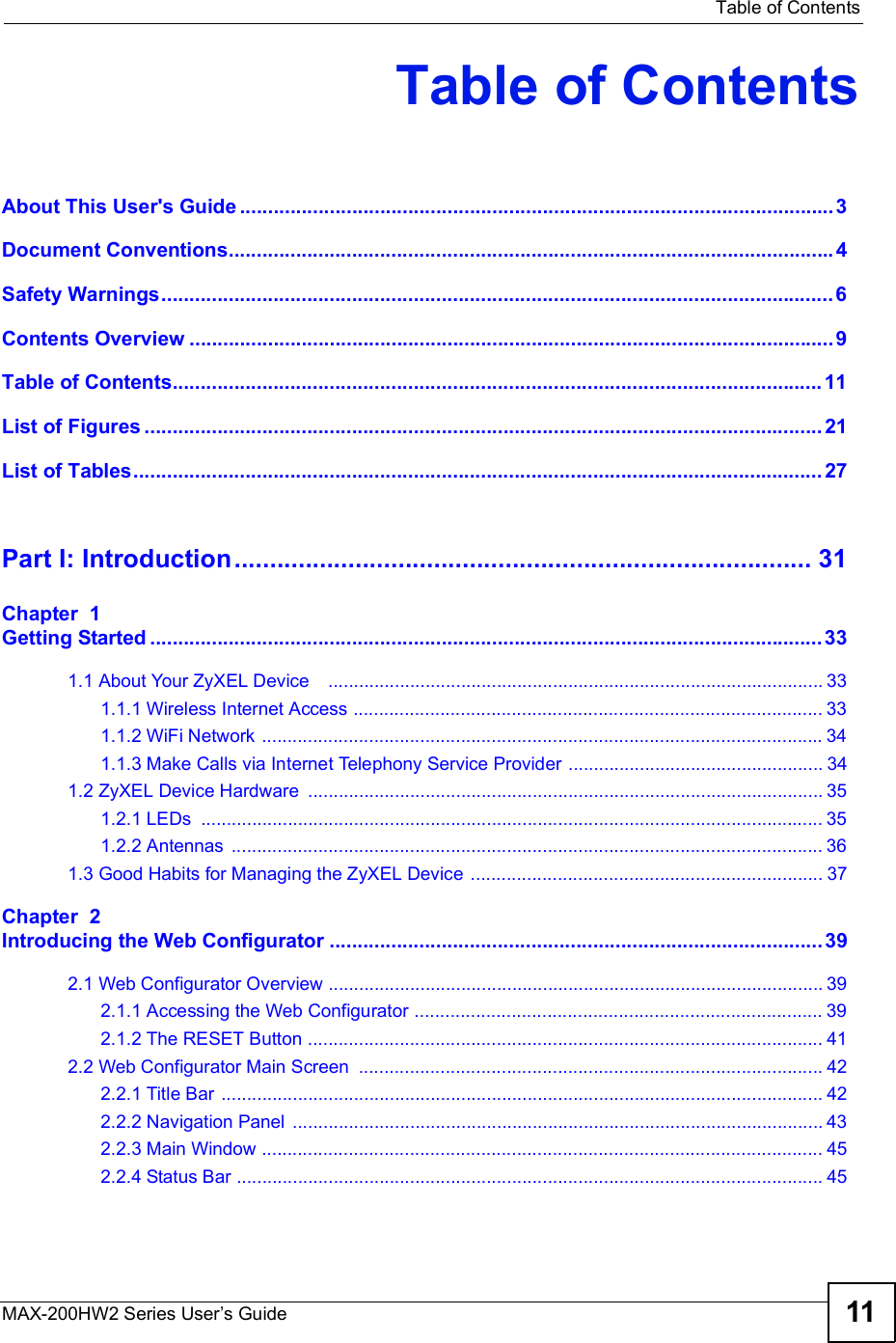
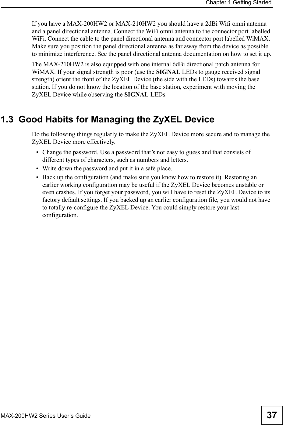
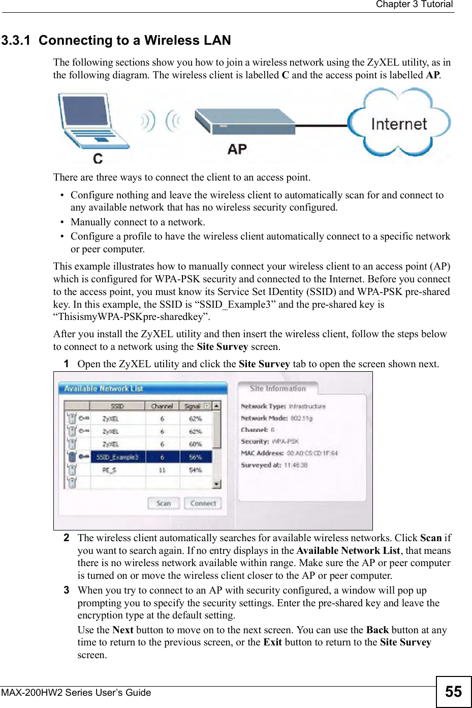
![Chapter 8WAN SetupMAX-200HW2 Series User s Guide112Use the WiMAX Frequency screen to define the radio frequencies to be searched for available wireless connections. See Section 8.4.2.1 on page 113 for an example of using the WiMAX Frequency screen.It may take several minutes for the ZyXEL Device to find a connection. The ZyXEL Device searches the DL Frequency settings in ascending numerical order, from [0] to [9]. If you enter a 0 in a DL Frequency field, the ZyXEL Device immediately moves on to the next DL Frequency field. When the ZyXEL Device connects to a base station, the values in this screen are automatically set to the base station!s frequency. The next time the ZyXEL Device searches for a connection, it searches only this frequency. If you want the ZyXEL Device to search other frequencies, enter them in the DL Frequency fields.The following table describes some examples of DL Frequency settings.Click Network > WAN > WiMAX Frequency to display the screen shown next.Table 34 DL Frequency Example SettingsEXAMPLE 1 EXAMPLE 2DL Frequency [0]:25000002500000DL Frequency [1]:25500002550000DL Frequency [2] 02600000DL Frequency [3]:00DL Frequency [4]:00The ZyXEL Device searches at 2500000 kHz, and then searches at 2550000 kHz if it has not found a connection.The ZyXEL Devicesearches at 2500000 kHz and then at 2550000 kHz if it has not found an available connection. If it still does not find an available connection, it searches at 2600000 kHz.](https://usermanual.wiki/ZyXEL-Communications/MAX200HW2.User-manual-revised-1/User-Guide-913209-Page-110.png)
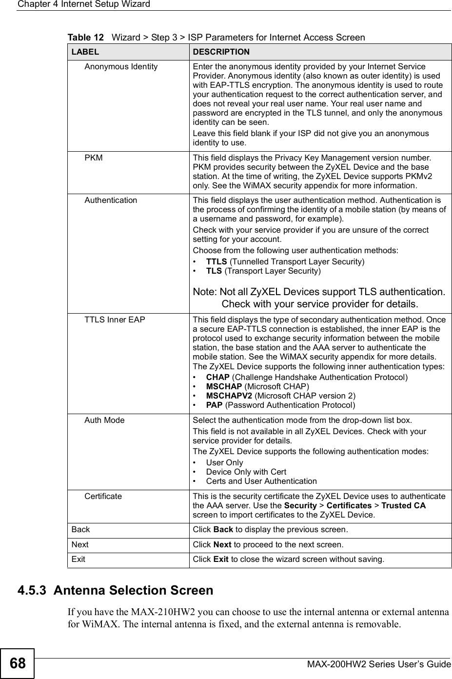
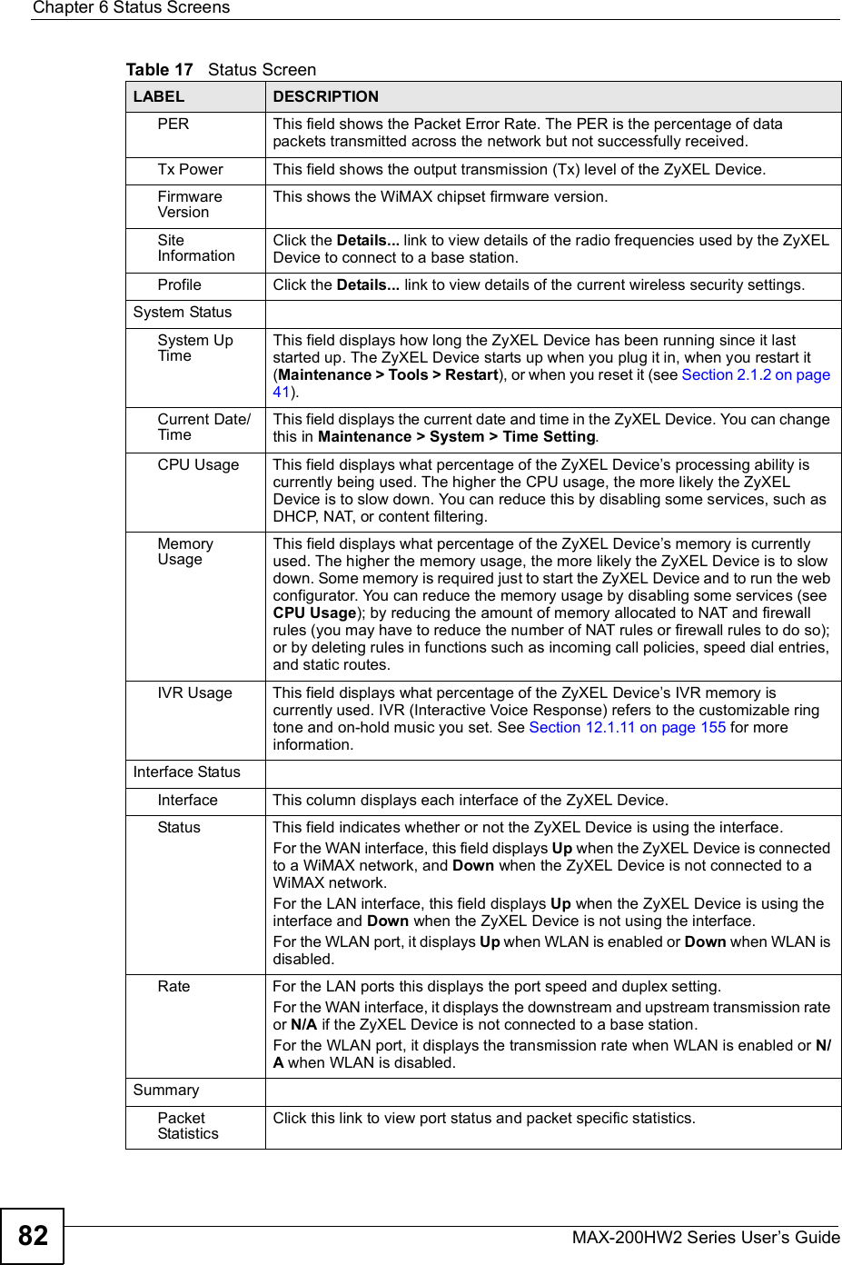
![Chapter 8WAN SetupMAX-200HW2 Series User s Guide 113Figure 70 Network > WAN >WiMAX FrequencyThe following table describes the labels in this screen.8.4.2.1 Using the WiMAX Frequency Screen: ExampleIn this example, your Internet service provider has given you a list of supported frequencies, as follows.Use the WiMAX Frequency screen to enter the frequencies you want the ZyXEL Device to scan for a connection to a base station. 1In the DL Frequency [0] field, enter 2500000 (2500000 kilohertz (kHz) is equal to 2.5 gigahertz).2In the DL Frequency [1] field, enter 2525000.3In the DL Frequency [2] field, enter 2600000.4In the DL Frequency [3] field, enter 2625000.Leave the rest of the DL Frequency fields at zero. The screen appears as follows.Table 35 Network > WAN > WiMAX FrequencyLABEL DESCRIPTIONDL Frequency [0] ~ [9]These fields show the downlink frequency settings in kilohertz (kHz). Enter values in these fields to have the ZyXEL Device scan these frequencies for available channels in ascending numerical order. Contact your service provider for details of supported frequencies.ApplyClick this button to save your settings.ResetClick this button to return all the fields in this screen to their default values.Table 36 Example Supported Frequencies (GHz)2.5 2.5252.62.625](https://usermanual.wiki/ZyXEL-Communications/MAX200HW2.User-manual-revised-1/User-Guide-913209-Page-111.png)
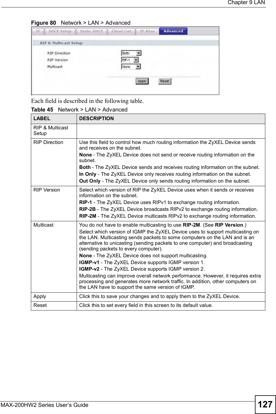
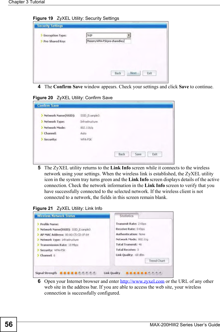
![Chapter 8WAN SetupMAX-200HW2 Series User s Guide114Figure 71 Completing the WiMAX Frequency Screen5Click Apply. The ZyXEL Device stores your settings. When the ZyXEL Device searches for available frequencies, it scans all frequencies from DL Frequency [0] to DL Frequency [3]. When it finds an available connection, the fields in this screen will be automatically set to use that frequency.8.5 Configuring Advanced WAN SettingsClick Network > WAN > Advanced to display the following screen.Figure 72 Network > WAN > Advanced](https://usermanual.wiki/ZyXEL-Communications/MAX200HW2.User-manual-revised-1/User-Guide-913209-Page-112.png)