ZyXEL Communications MAX200HW2 WiMAX Router User Manual UserMan I88MAX200HW2 revised
ZyXEL Communications Corporation WiMAX Router UserMan I88MAX200HW2 revised
Contents
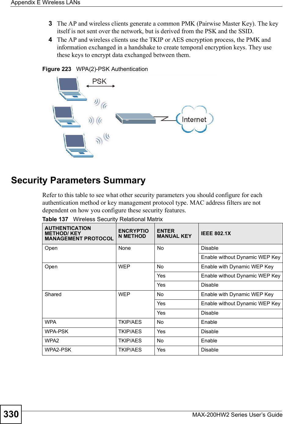
- 1. User manual revised 1
- 2. User manual revised 2
- 3. User manual revised 3
- 4. User manal revised 3
User manual revised 3
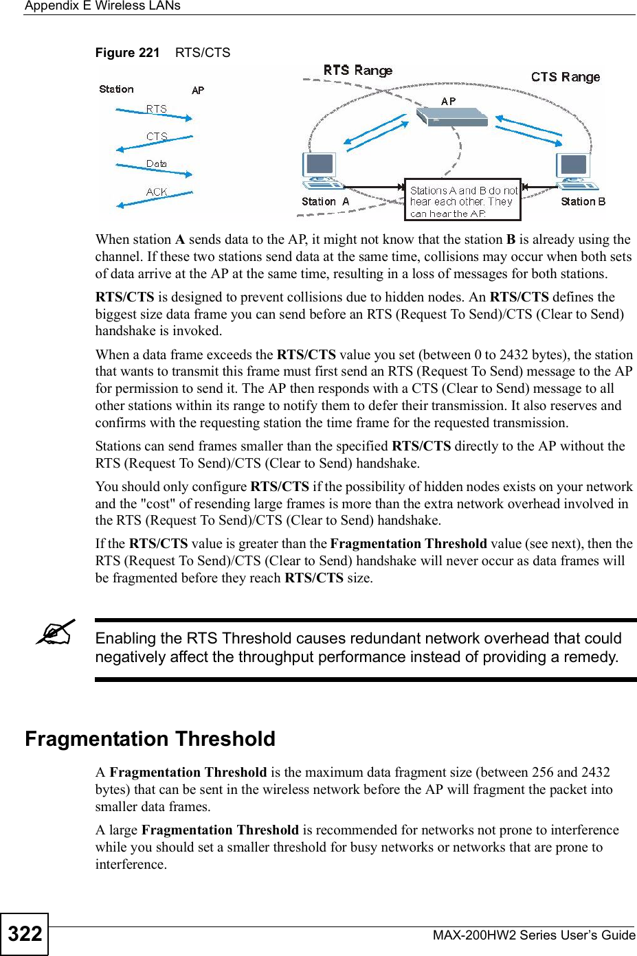
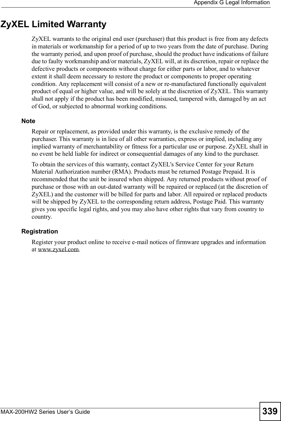
![Chapter 22LogsMAX-200HW2 Series User s Guide 253Table 116 FSM Logs: Callee SideLOG MESSAGE DESCRIPTIONVoIP Call Start from SIP[SIP Port Number]A VoIP phone call came to the ZyXEL Device from the listed SIP number.VoIP Call Established Ph[Phone Port] <- Outgoing Call NumberA VoIP phone call was set up from the listed SIP number to the ZyXEL Device.VoIP Call End Phone[Phone Port]A VoIP phone call that came into the ZyXEL Device has terminated.Table 117 Lifeline LogsLOG MESSAGE DESCRIPTIONPSTN Call Start A PSTN call has been initiated.PSTN Call End A PSTN call has terminated.PSTN Call Established A PSTN call has been set up.](https://usermanual.wiki/ZyXEL-Communications/MAX200HW2.User-manual-revised-3/User-Guide-913211-Page-1.png)


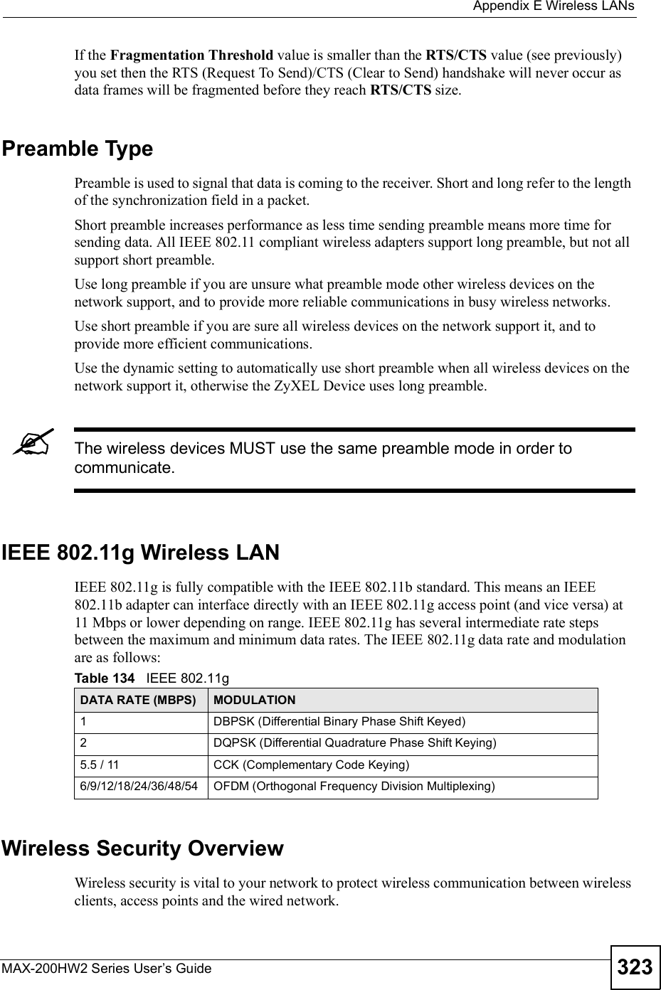
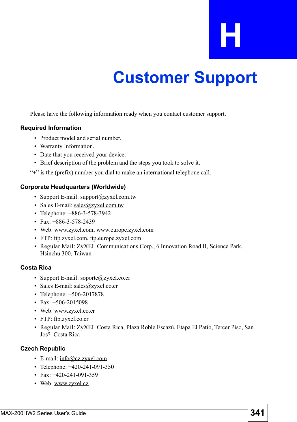
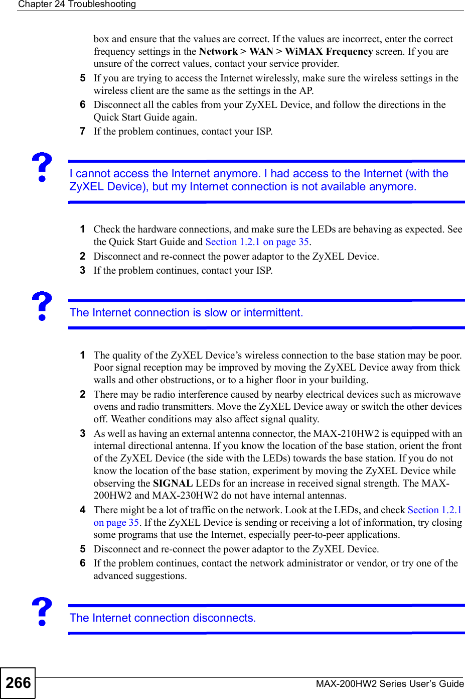
![Chapter 24TroubleshootingMAX-200HW2 Series User s Guide 265Advanced Suggestions Try to access the ZyXEL Device using another service, such as Telnet. If you can access the ZyXEL Device, check the remote management settings and firewall rules to find out why the ZyXEL Device does not respond to HTTP. If your computer is connected wirelessly, use a computer that is connected to a LAN/ETHERNET port.I can see the Login screen, but I cannot log in to the ZyXEL Device.1Make sure you have entered the user name and password correctly. The default user name is admin, and the default password is 1234. These fields are case-sensitive, so make sure [Caps Lock] is not on.2You cannot log in to the web configurator while someone is using Telnet to access the ZyXEL Device. Log out of the ZyXEL Device in the other session, or ask the person who is logged in to log out.3Disconnect and re-connect the power adaptor or cord to the ZyXEL Device.4If this does not work, you have to reset the ZyXEL Device to its factory defaults. See Section 23.2.3 on page 257.I cannot Telnet to the ZyXEL Device.See the troubleshooting suggestions for I cannot see or access the Login screen in the web configurator. Ignore the suggestions about your browser.24.3 Internet AccessI cannot access the Internet.1Check the hardware connections, and make sure the LEDs are behaving as expected. See the Quick Start Guide and Section 1.2.1 on page 35.2Make sure you entered your ISP account information correctly in the wizard. These fields are case-sensitive, so make sure [Caps Lock] is not on.3Check your security settings. In the web configurator, go to the Status screen. Click the Details... link next to Profile in the WiMAX Information box and make sure that you are using the correct security settings for your Internet account.4Check your WiMAX settings. The ZyXEL Device may have been set to search the wrong frequencies for a wireless connection. In the web configurator, go to the Statusscreen. Click the Details... link next to Site Information in the WiMAX Information](https://usermanual.wiki/ZyXEL-Communications/MAX200HW2.User-manual-revised-3/User-Guide-913211-Page-13.png)


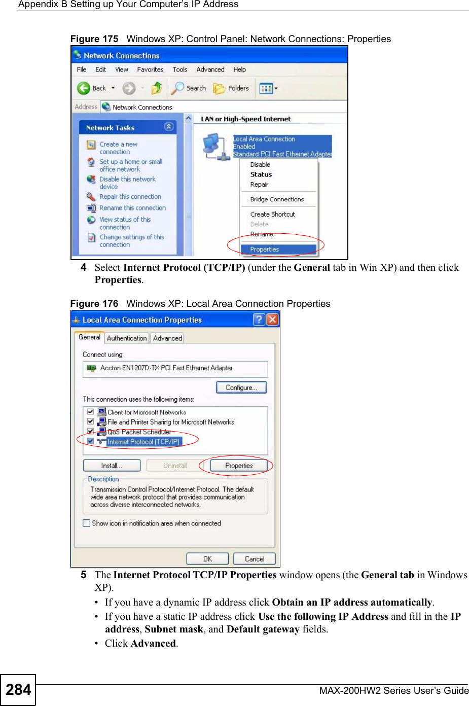
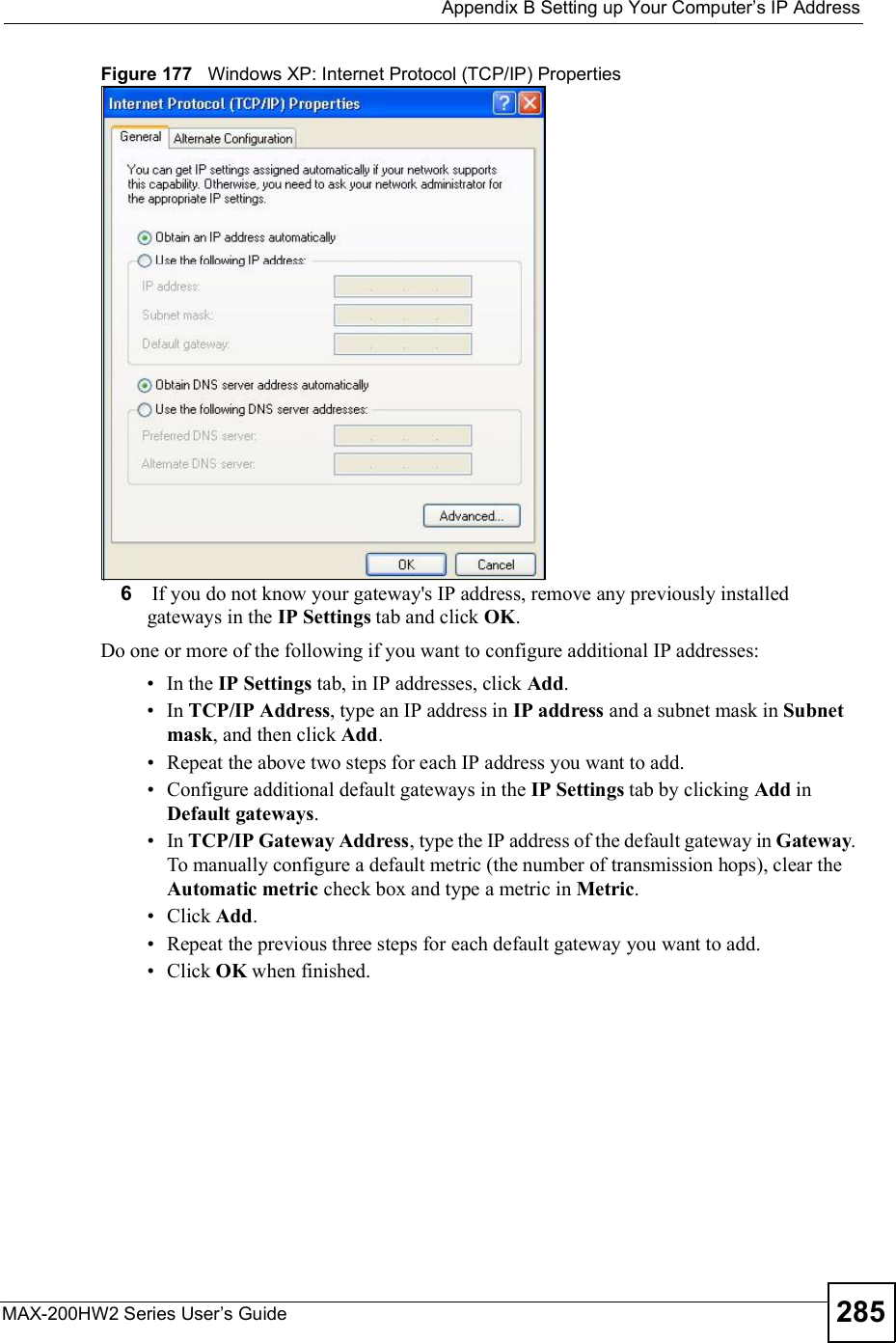
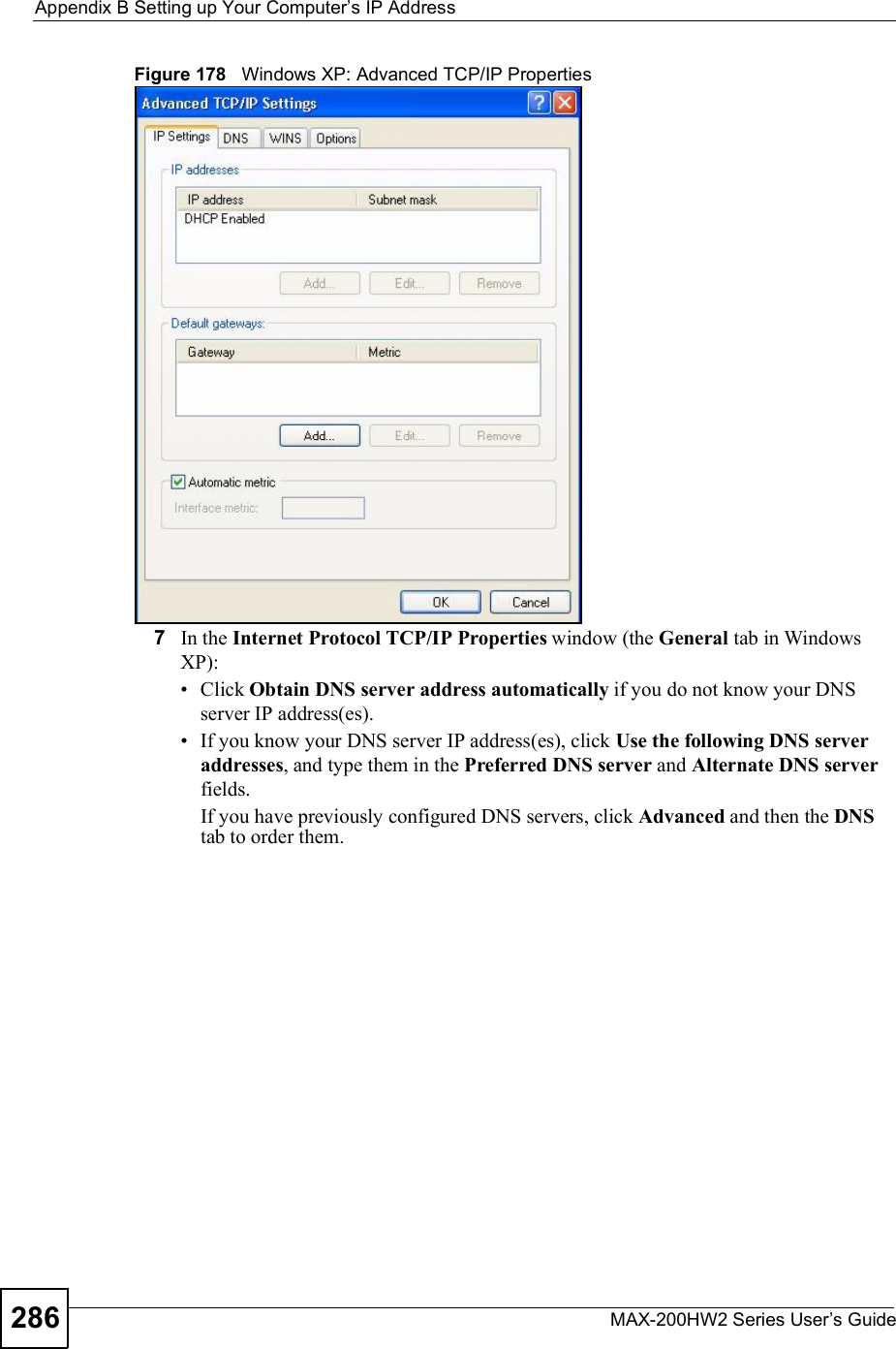
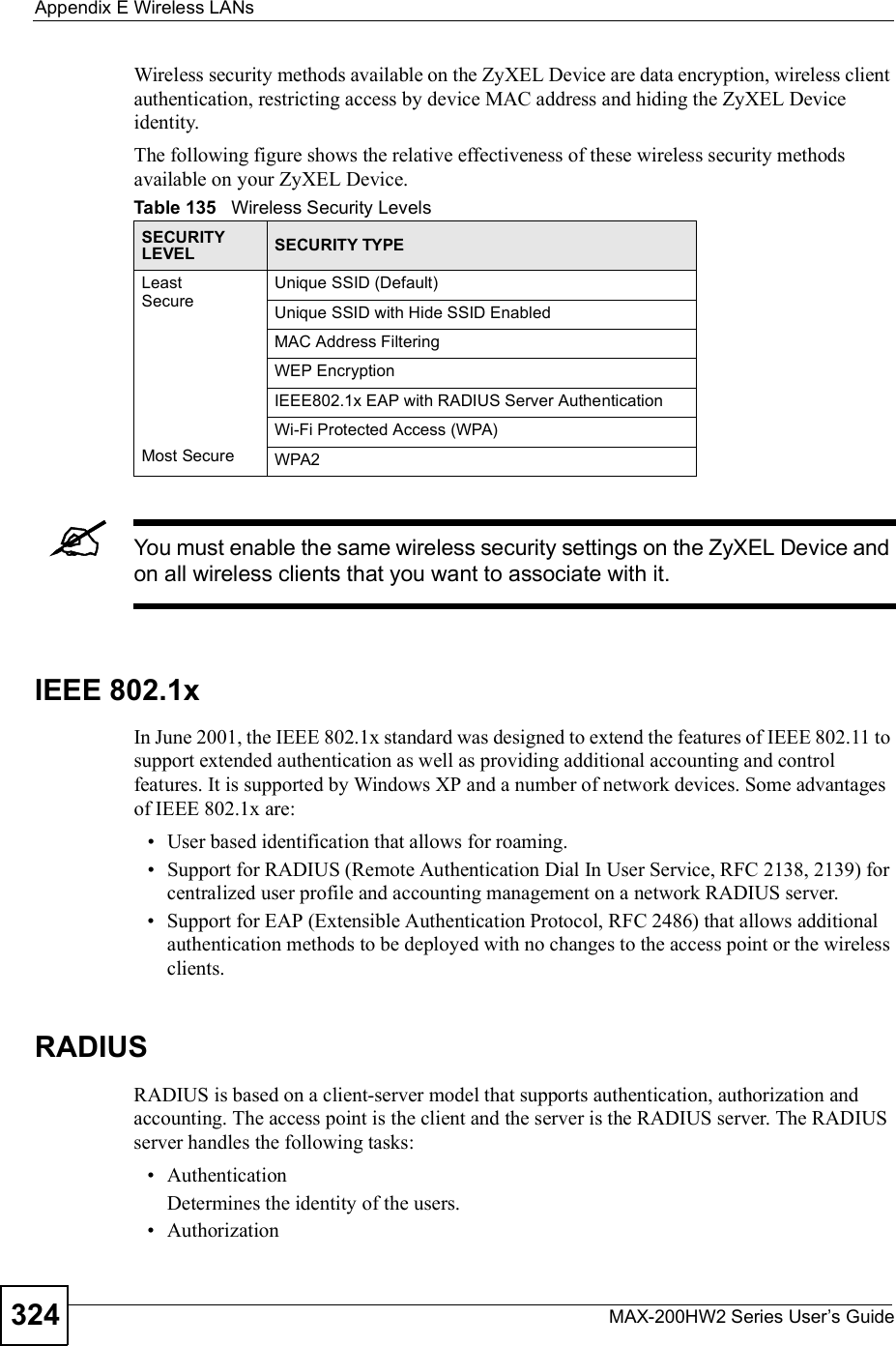
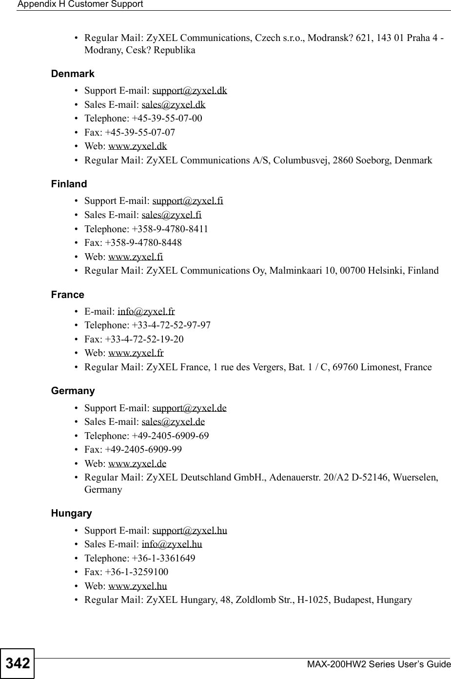
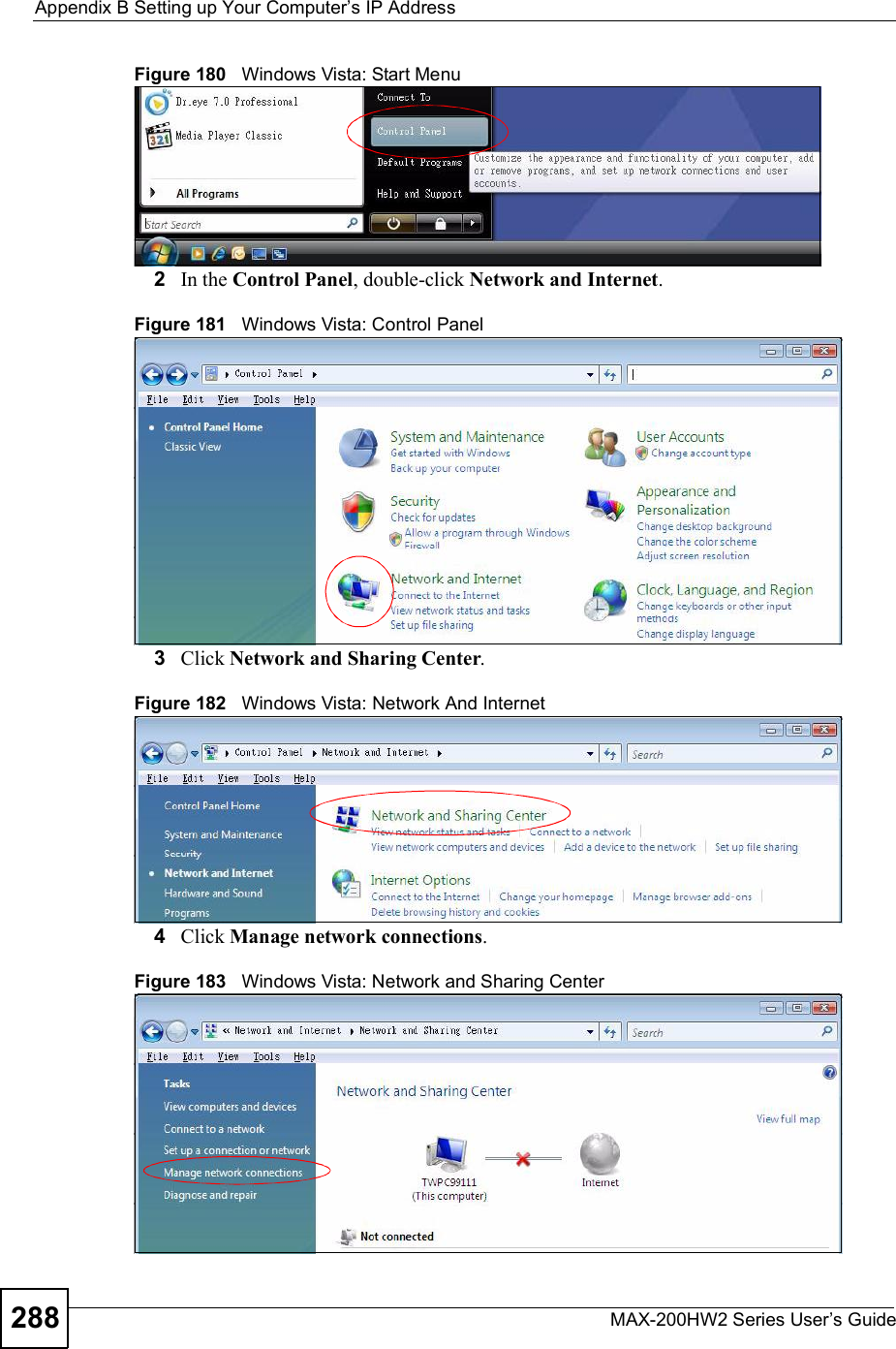
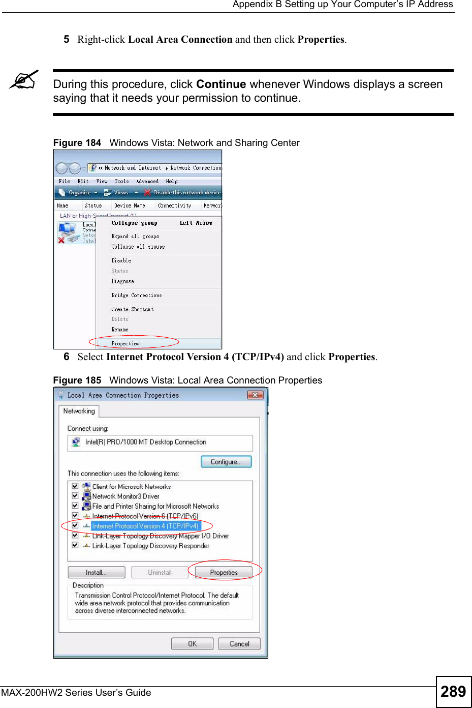
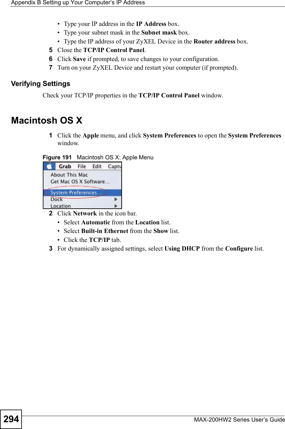
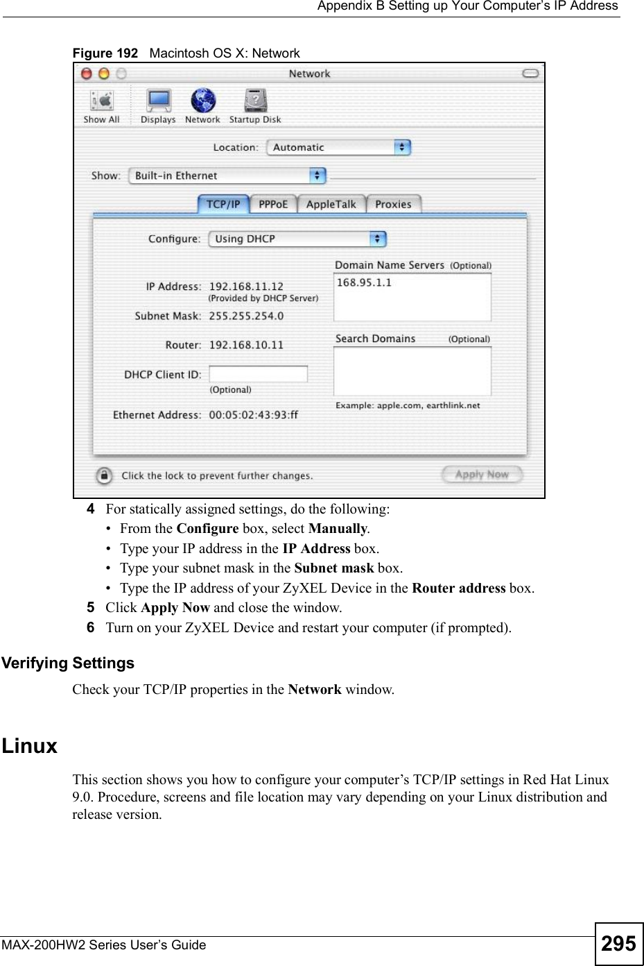
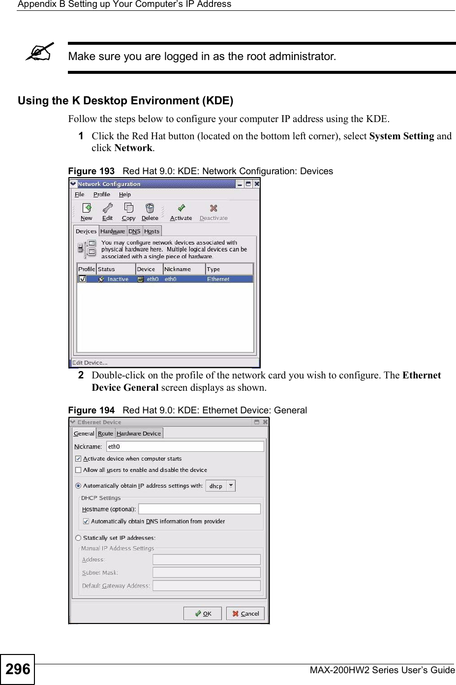
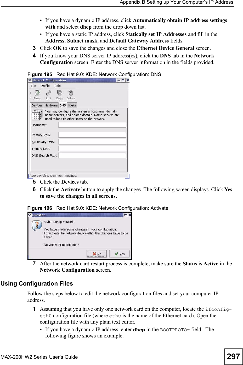
![Appendix BSetting up Your Computer s IP AddressMAX-200HW2 Series User s Guide 287Figure 179 Windows XP: Internet Protocol (TCP/IP) Properties8Click OK to close the Internet Protocol (TCP/IP) Properties window.9Click Close (OK in Windows 2000/NT) to close the Local Area Connection Properties window.10 Close the Network Connections window (Network and Dial-up Connections in Windows 2000/NT).11 Turn on your ZyXEL Device and restart your computer (if prompted).Verifying Settings1Click Start,All Programs,Accessories and then Command Prompt.2In the Command Prompt window, type "ipconfig" and then press [ENTER]. You can also open Network Connections, right-click a network connection, click Status and then click the Support tab.Windows VistaThis section shows screens from Windows Vista Enterprise Version 6.0.1Click the Start icon, Control Panel.](https://usermanual.wiki/ZyXEL-Communications/MAX200HW2.User-manual-revised-3/User-Guide-913211-Page-35.png)
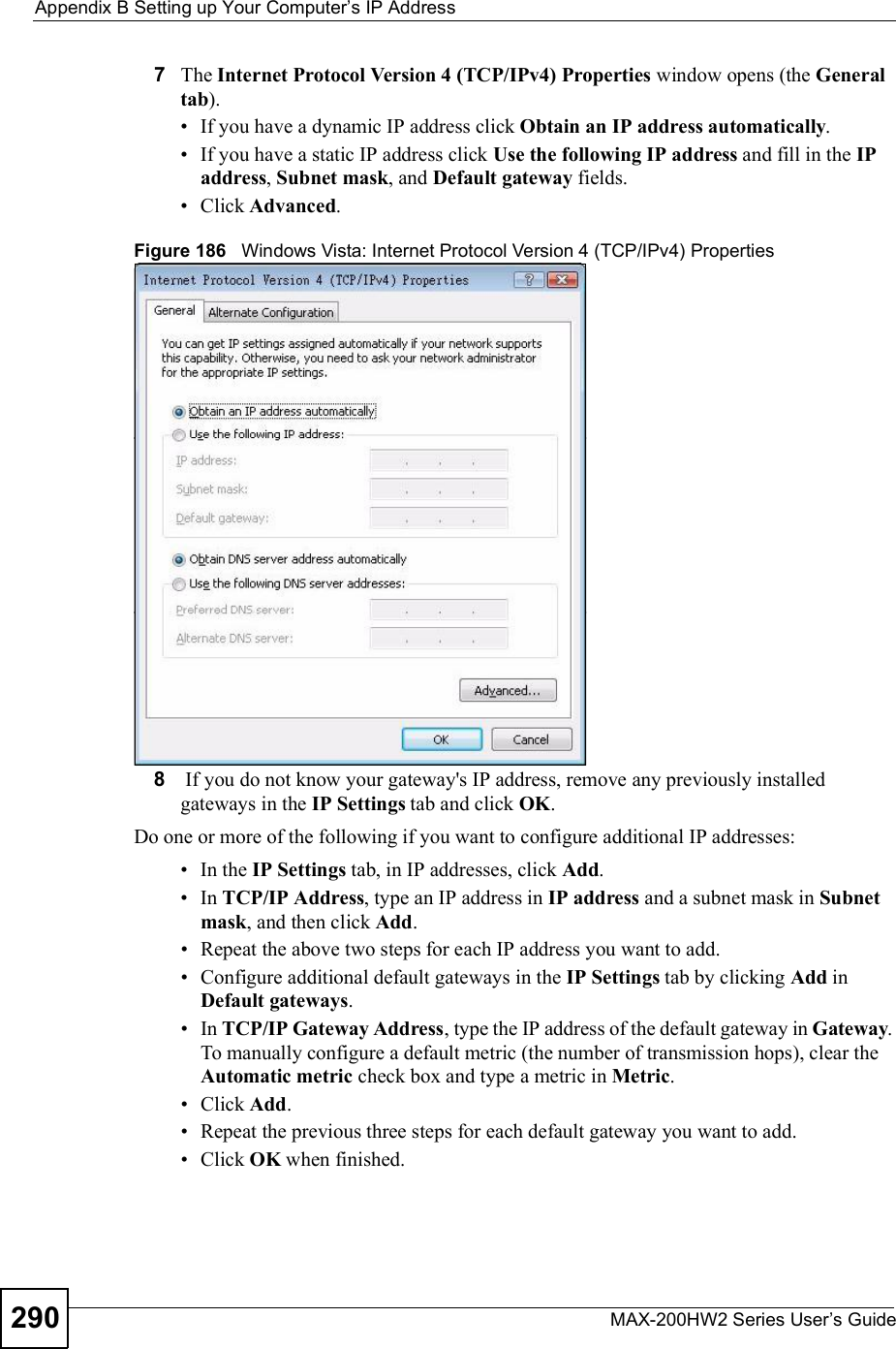
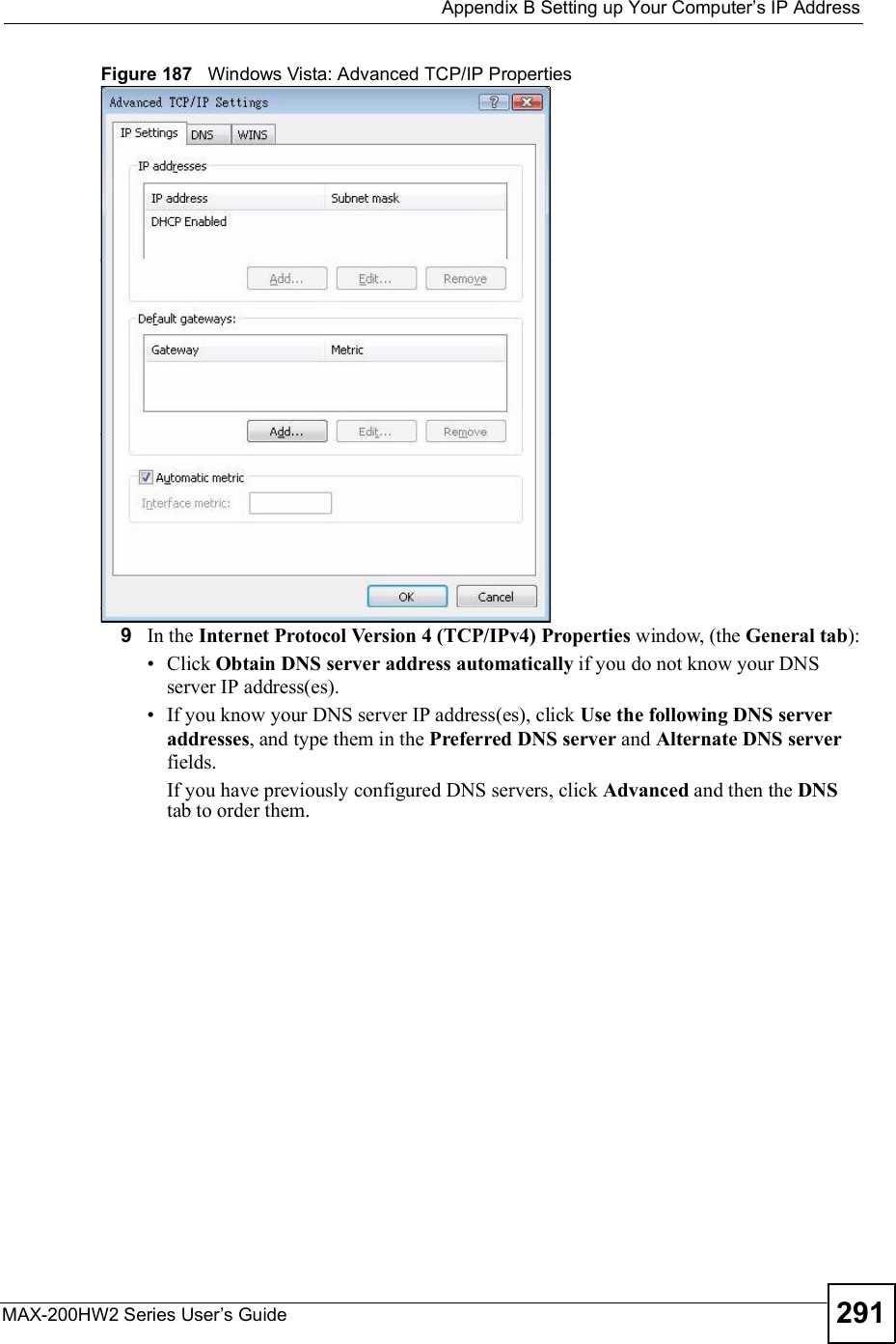
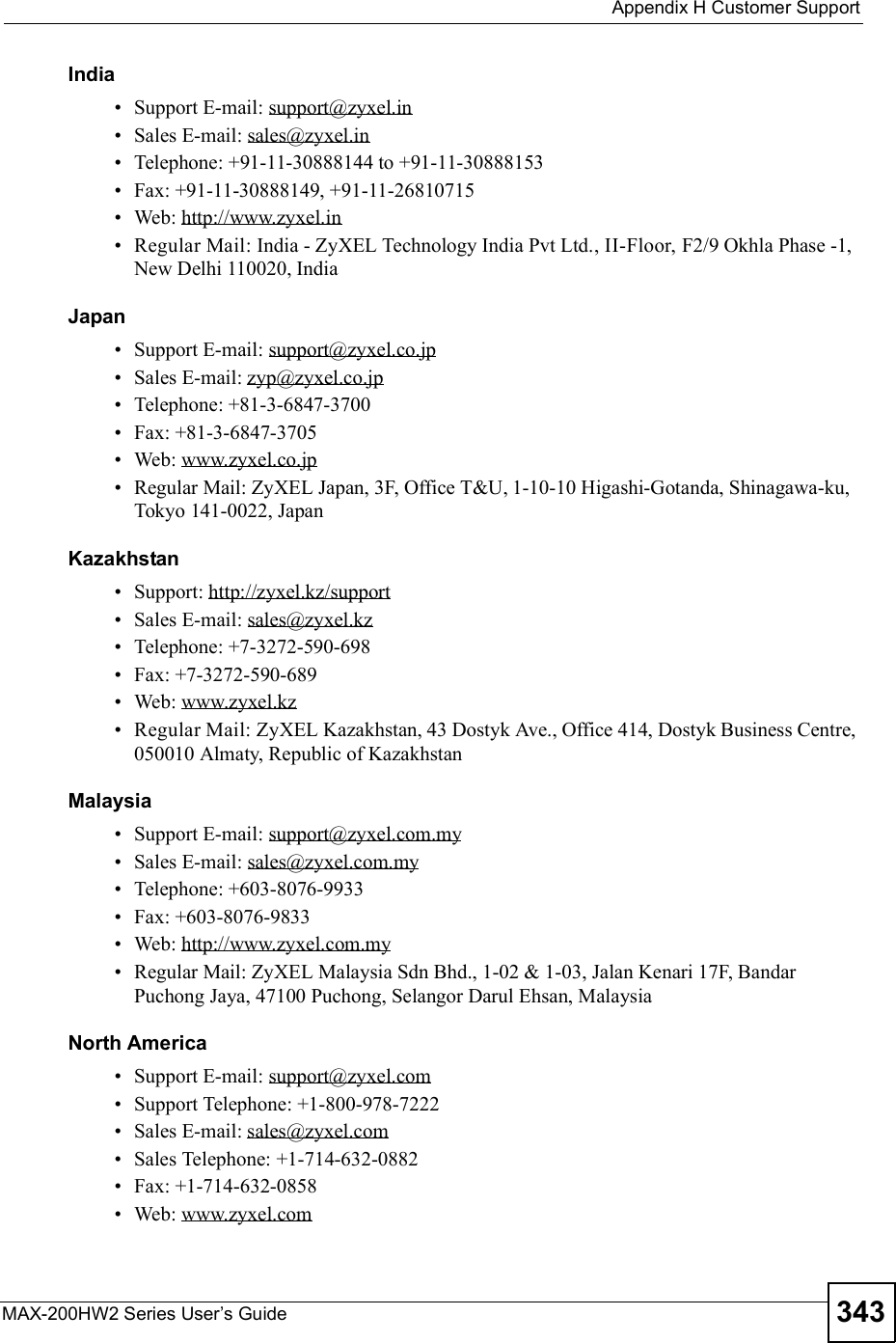
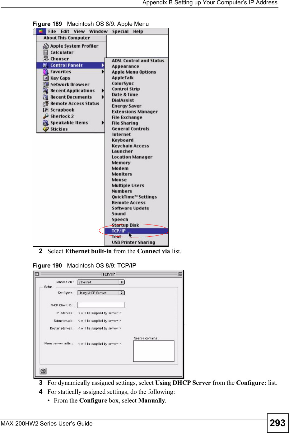
![Appendix BSetting up Your Computer s IP AddressMAX-200HW2 Series User s Guide292Figure 188 Windows Vista: Internet Protocol Version 4 (TCP/IPv4) Properties10 Click OK to close the Internet Protocol Version 4 (TCP/IPv4) Properties window.11 Click Close to close the Local Area Connection Properties window.12 Close the Network Connections window.13 Turn on your ZyXEL Device and restart your computer (if prompted).Verifying Settings1Click Start,All Programs,Accessories and then Command Prompt.2In the Command Prompt window, type "ipconfig" and then press [ENTER]. You can also open Network Connections, right-click a network connection, click Status and then click the Support tab.Macintosh OS 8/9 1Click the Apple menu, Control Panel and double-click TCP/IP to open the TCP/IPControl Panel.](https://usermanual.wiki/ZyXEL-Communications/MAX200HW2.User-manual-revised-3/User-Guide-913211-Page-40.png)
![Appendix BSetting up Your Computer s IP AddressMAX-200HW2 Series User s Guide298Figure 197 Red Hat 9.0: Dynamic IP Address Setting in ifconfig-eth0 If you have a static IP address, enter static in the BOOTPROTO= field. Type IPADDR= followed by the IP address (in dotted decimal notation) and type NETMASK=followed by the subnet mask. The following example shows an example where the static IP address is 192.168.1.10 and the subnet mask is 255.255.255.0. Figure 198 Red Hat 9.0: Static IP Address Setting in ifconfig-eth0 2If you know your DNS server IP address(es), enter the DNS server information in the resolv.conf file in the /etc directory. The following figure shows an example where two DNS server IP addresses are specified.Figure 199 Red Hat 9.0: DNS Settings in resolv.conf 3After you edit and save the configuration files, you must restart the network card. Enter ./network restart in the /etc/rc.d/init.d directory. The following figure shows an example.Figure 200 Red Hat 9.0: Restart Ethernet Card DEVICE=eth0ONBOOT=yesBOOTPROTO=dhcpUSERCTL=noPEERDNS=yesTYPE=EthernetDEVICE=eth0ONBOOT=yesBOOTPROTO=staticIPADDR=192.168.1.10NETMASK=255.255.255.0USERCTL=noPEERDNS=yesTYPE=Ethernetnameserver 172.23.5.1nameserver 172.23.5.2[root@localhost init.d]# network restartShutting down interface eth0: [OK]Shutting down loopback interface: [OK]Setting network parameters: [OK]Bringing up loopback interface: [OK]Bringing up interface eth0: [OK]](https://usermanual.wiki/ZyXEL-Communications/MAX200HW2.User-manual-revised-3/User-Guide-913211-Page-46.png)
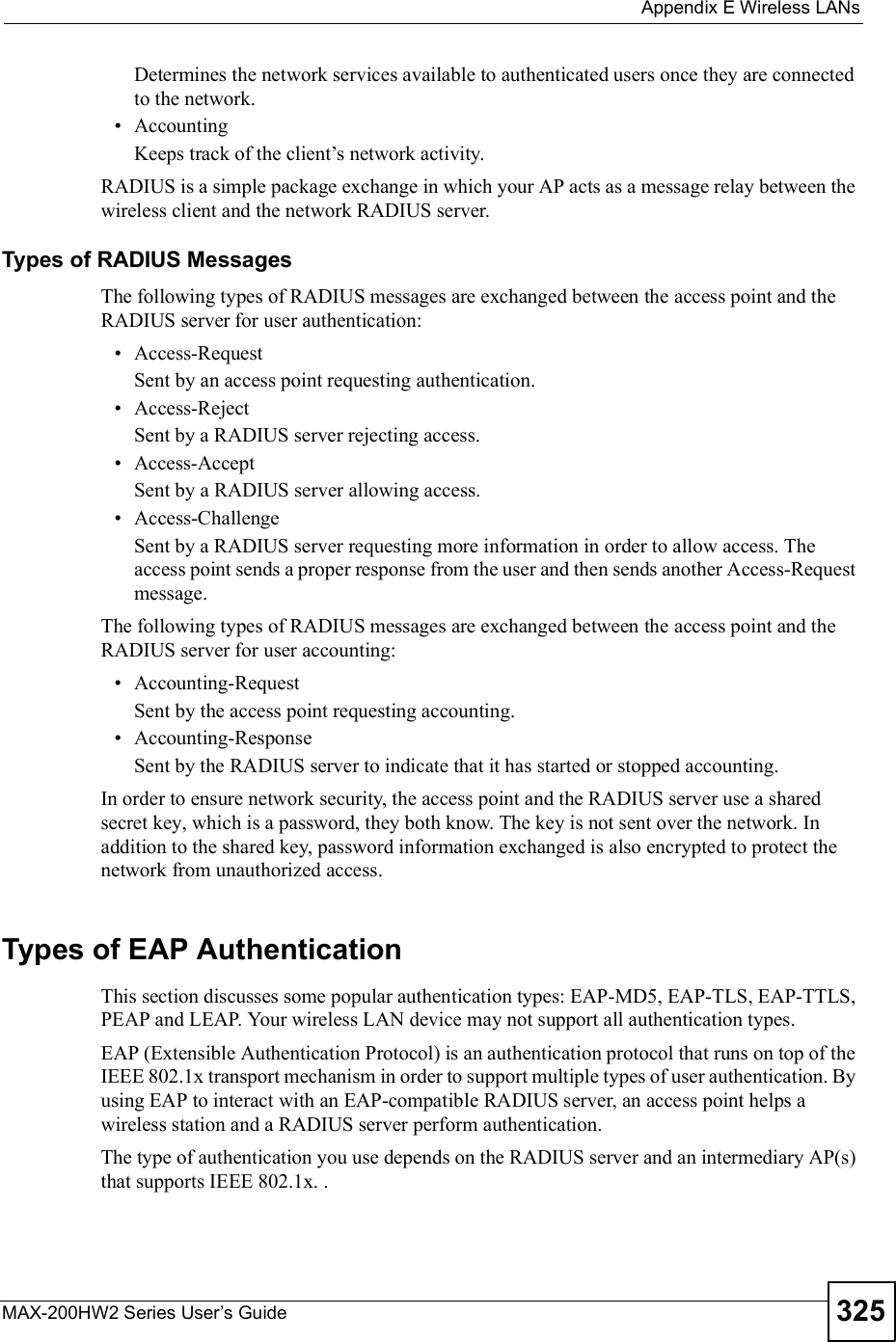
![Appendix BSetting up Your Computer s IP AddressMAX-200HW2 Series User s Guide 299Verifying SettingsEnter ifconfig in a terminal screen to check your TCP/IP properties. Figure 201 Red Hat 9.0: Checking TCP/IP Properties [root@localhost]# ifconfig eth0 Link encap:Ethernet HWaddr 00:50:BA:72:5B:44 inet addr:172.23.19.129 Bcast:172.23.19.255 Mask:255.255.255.0 UP BROADCAST RUNNING MULTICAST MTU:1500 Metric:1 RX packets:717 errors:0 dropped:0 overruns:0 frame:0 TX packets:13 errors:0 dropped:0 overruns:0 carrier:0 collisions:0 txqueuelen:100 RX bytes:730412 (713.2 Kb) TX bytes:1570 (1.5 Kb) Interrupt:10 Base address:0x1000 [root@localhost]#](https://usermanual.wiki/ZyXEL-Communications/MAX200HW2.User-manual-revised-3/User-Guide-913211-Page-47.png)