ZyXEL Communications MAX306 2.5GHz MIMO Outdoor CPE User Manual MAX 306HW2 Series UG v1 ed1 2009 06 29
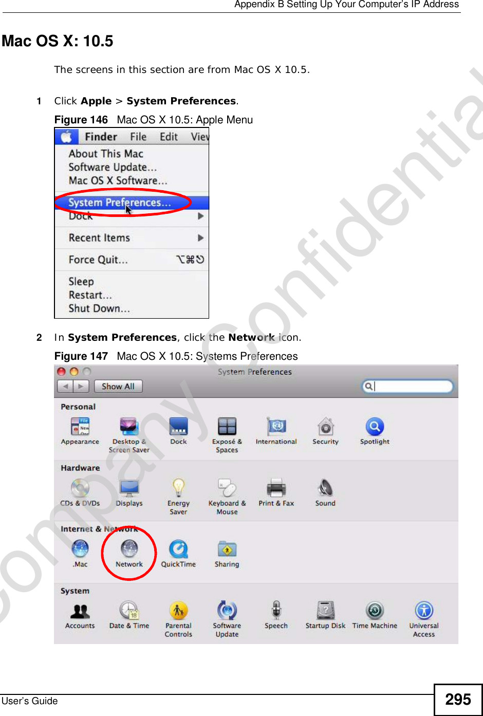
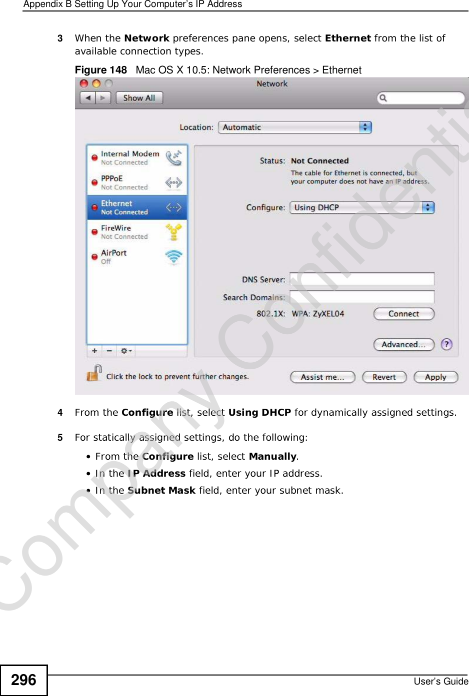
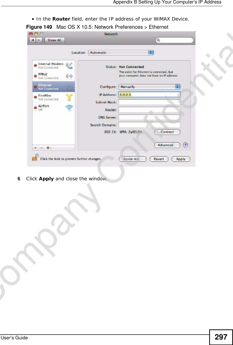
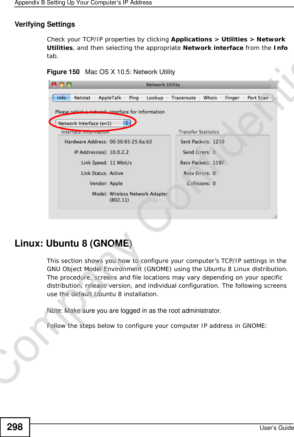
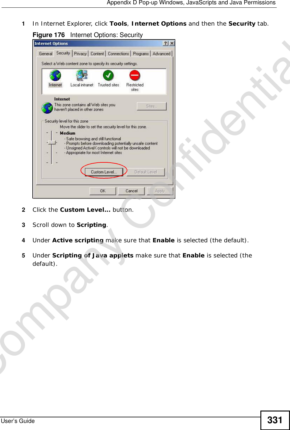
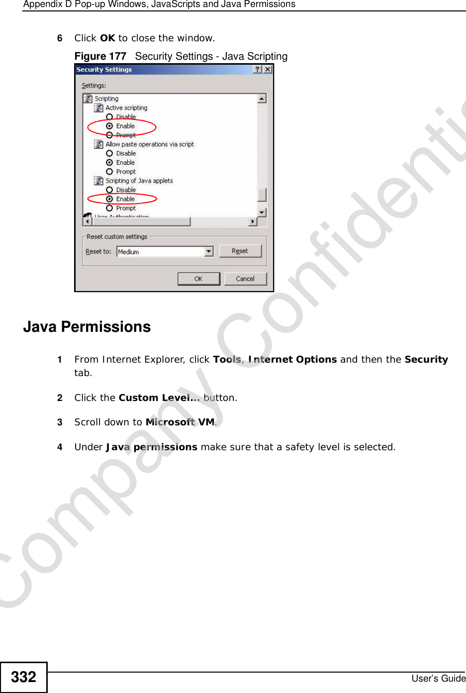
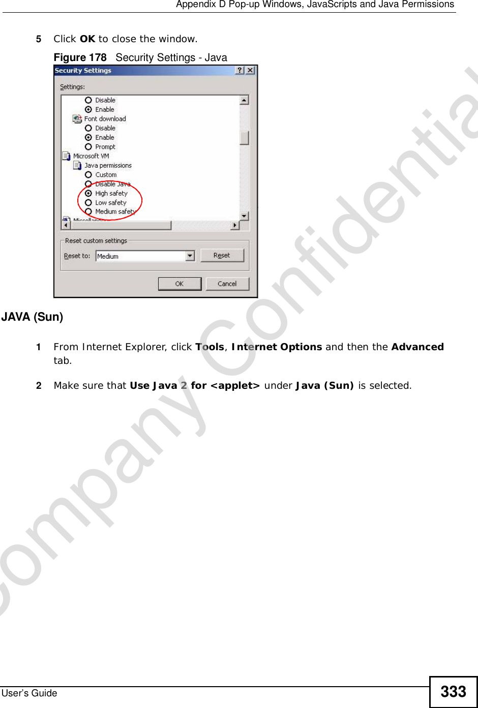
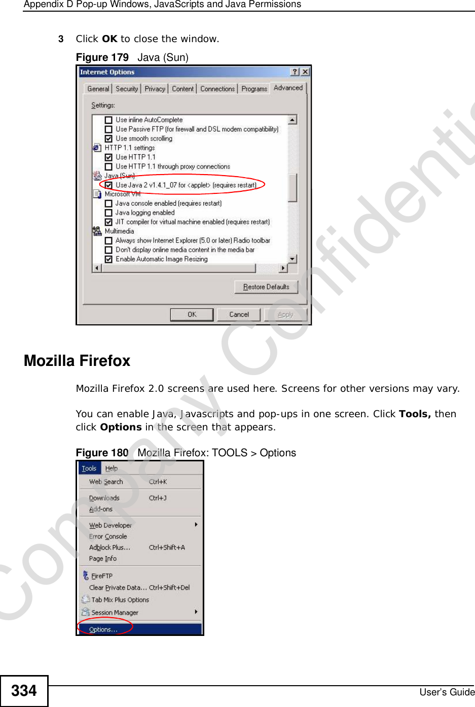
ZyXEL Communications Corporation 2.5GHz MIMO Outdoor CPE MAX 306HW2 Series UG v1 ed1 2009 06 29
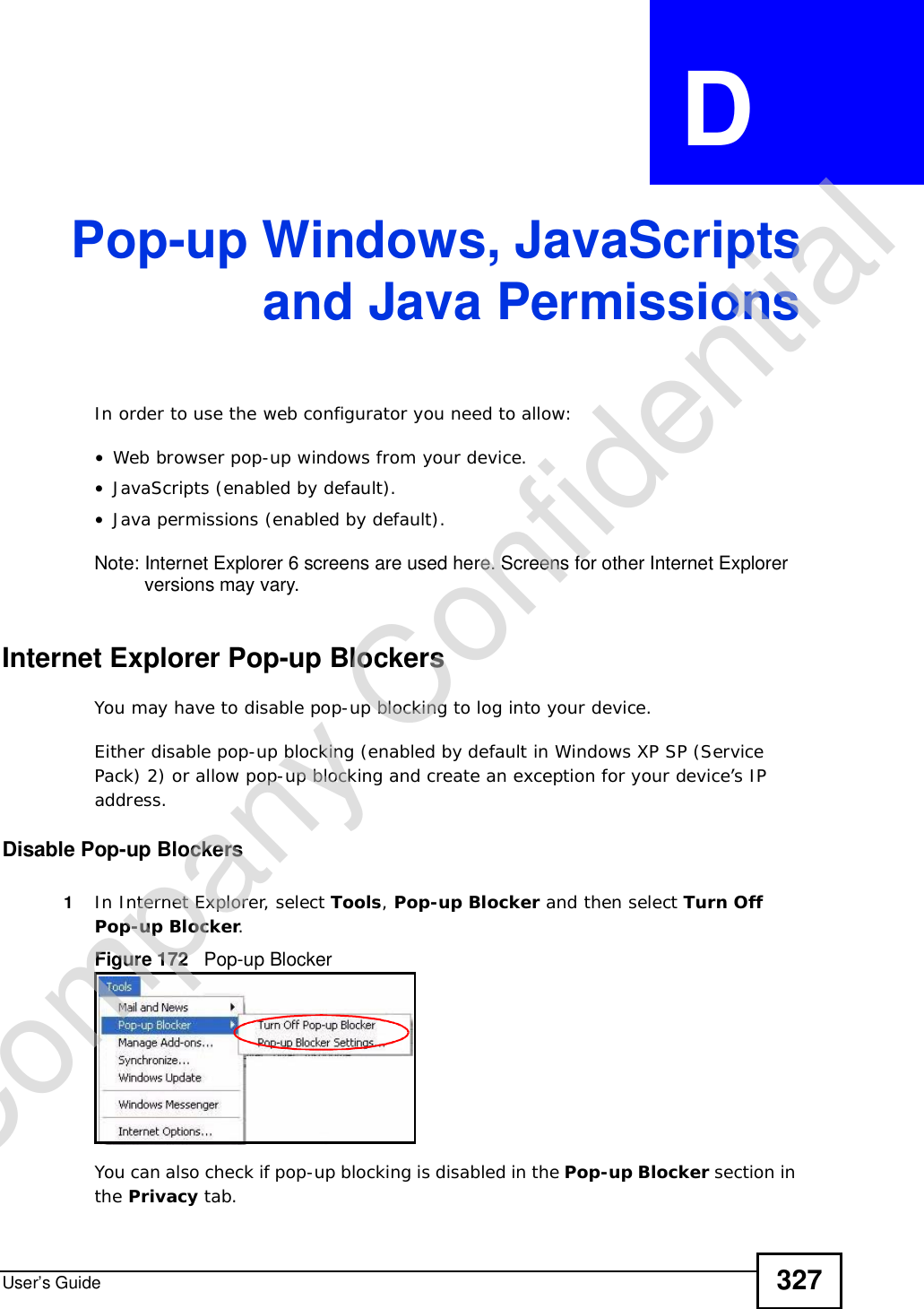
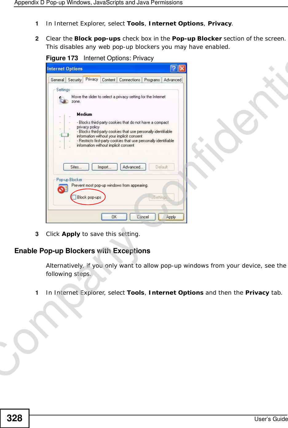
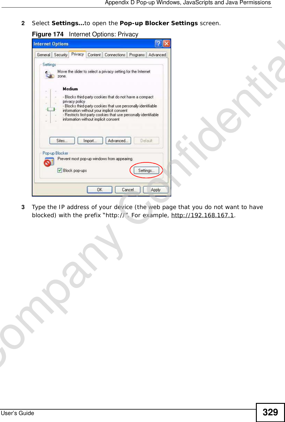
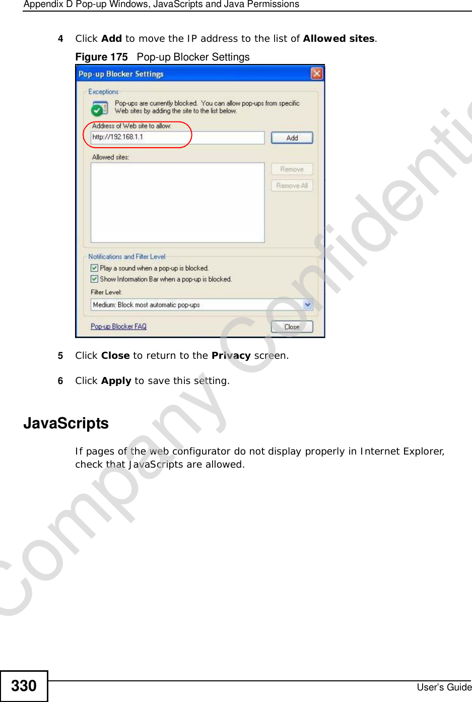
Contents
- 1. Manual Part 1
- 2. Manual Part 2
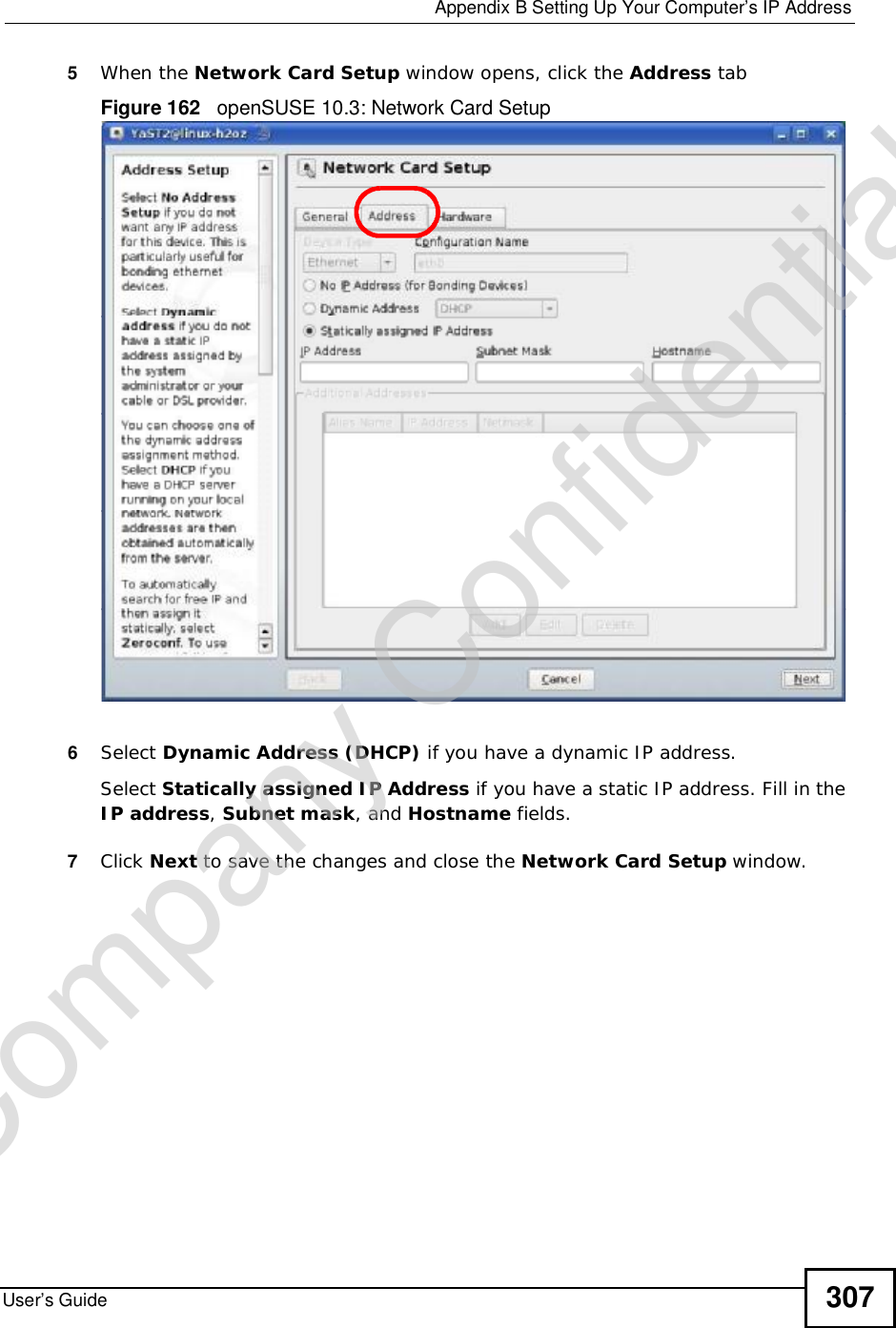
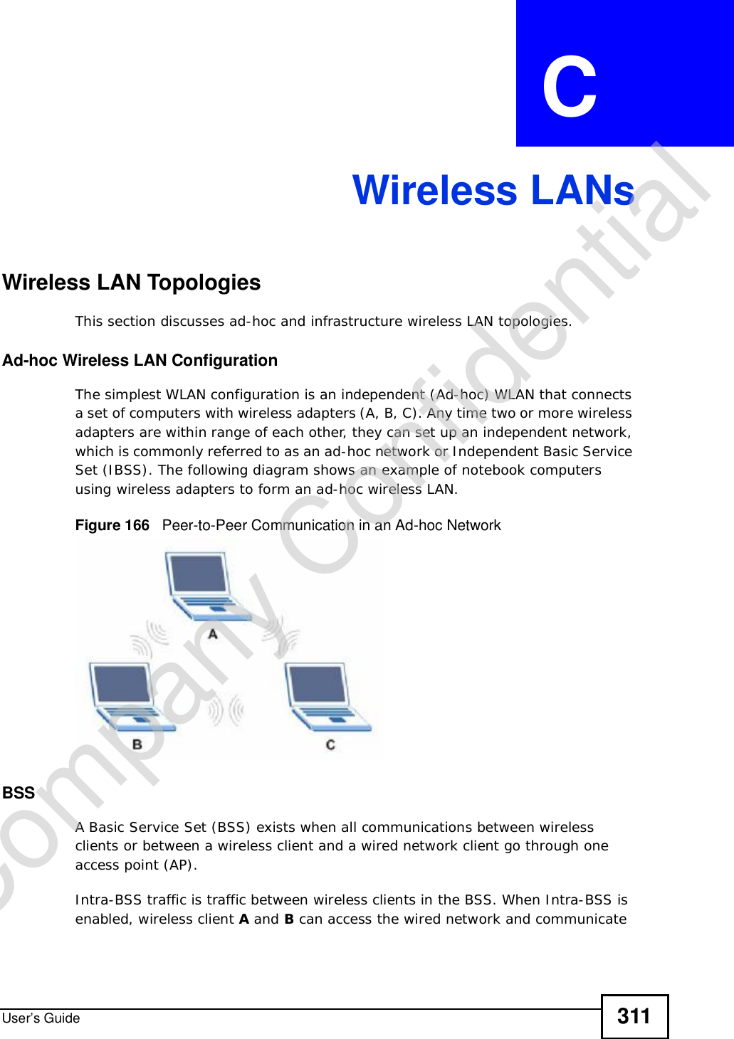
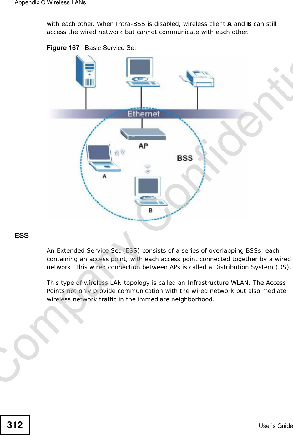
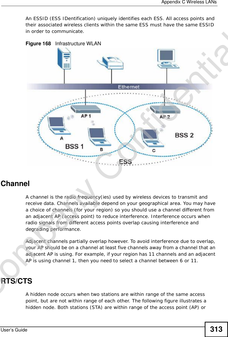
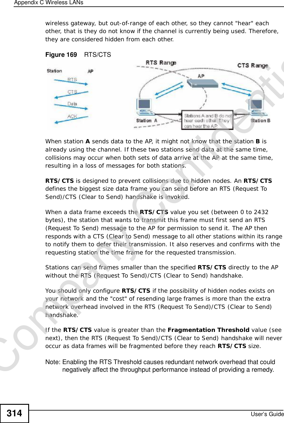
Manual Part 2
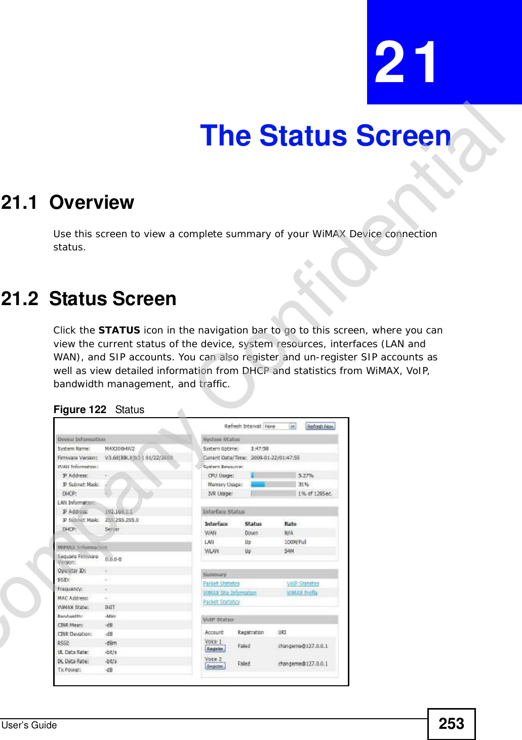
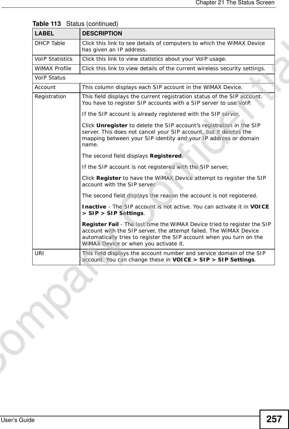
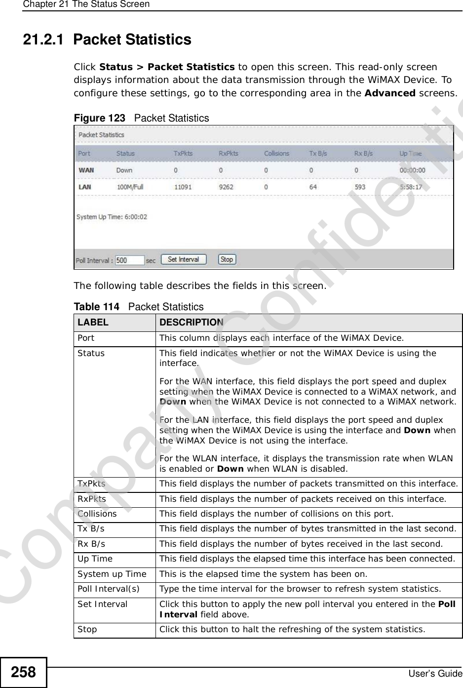
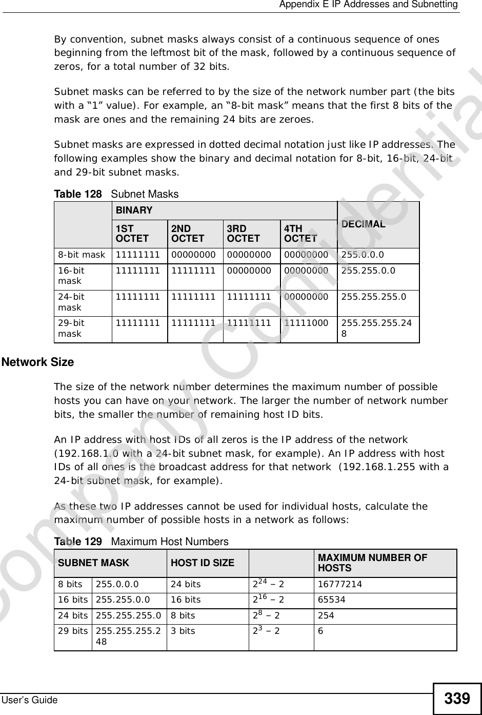
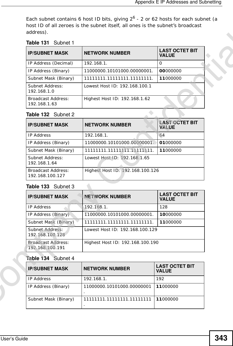
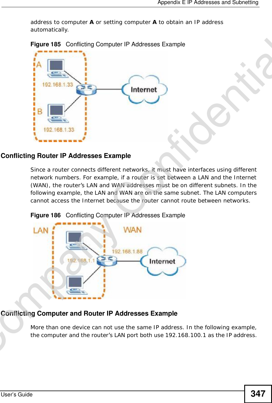
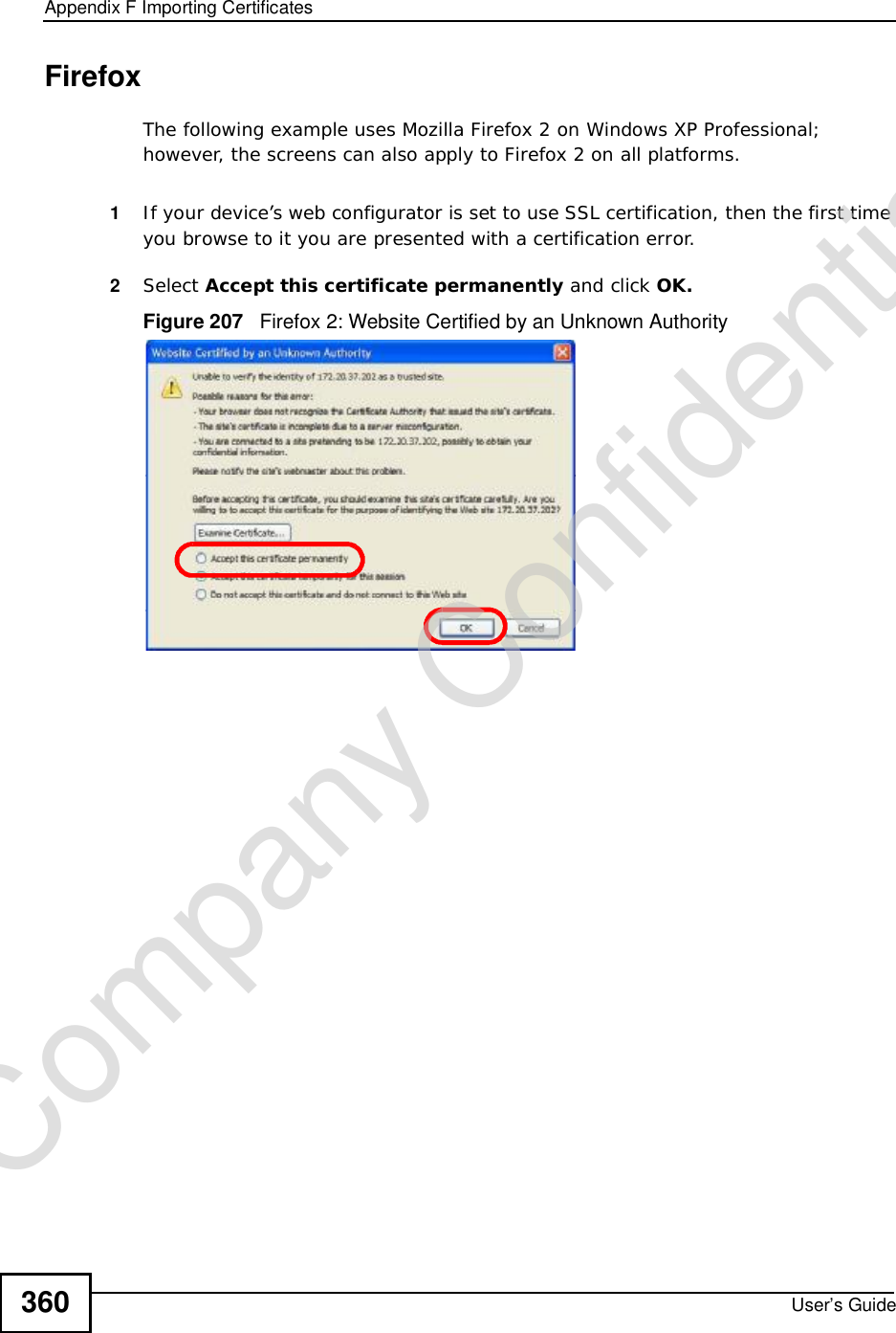
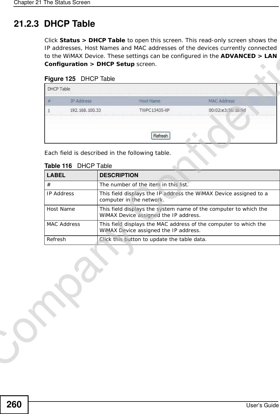
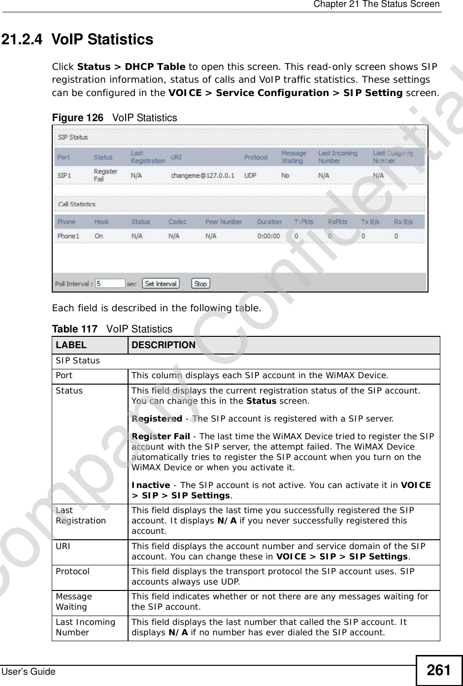
![Chapter 21The Status ScreenUser’s Guide 25921.2.2 WiMAX Site InformationClick Status > WiMAX Site Information to open this screen. This read-only screen shows WiMAX frequency information for the WiMAX Device. These settings can be configured in the ADVANCED > WAN Configuration > WiMAX Configuration screen.Figure 124 WiMAX Site Information The following table describes the labels in this screen. Table 115 WiMAX Site InformationLABEL DESCRIPTIONDL Frequency[0] ~ [19]These fields show the downlink frequency settings in kilohertz (kHz). These settings determine how the WiMAX Device searches for an available wireless connection.Company Confidential](https://usermanual.wiki/ZyXEL-Communications/MAX306.Manual-Part-2/User-Guide-1135856-Page-9.png)
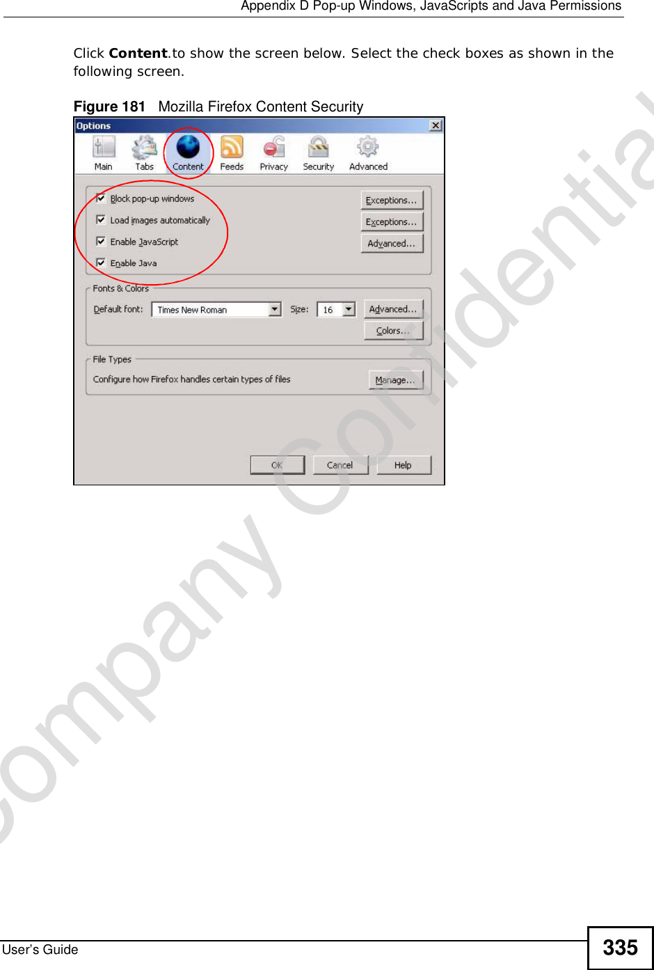
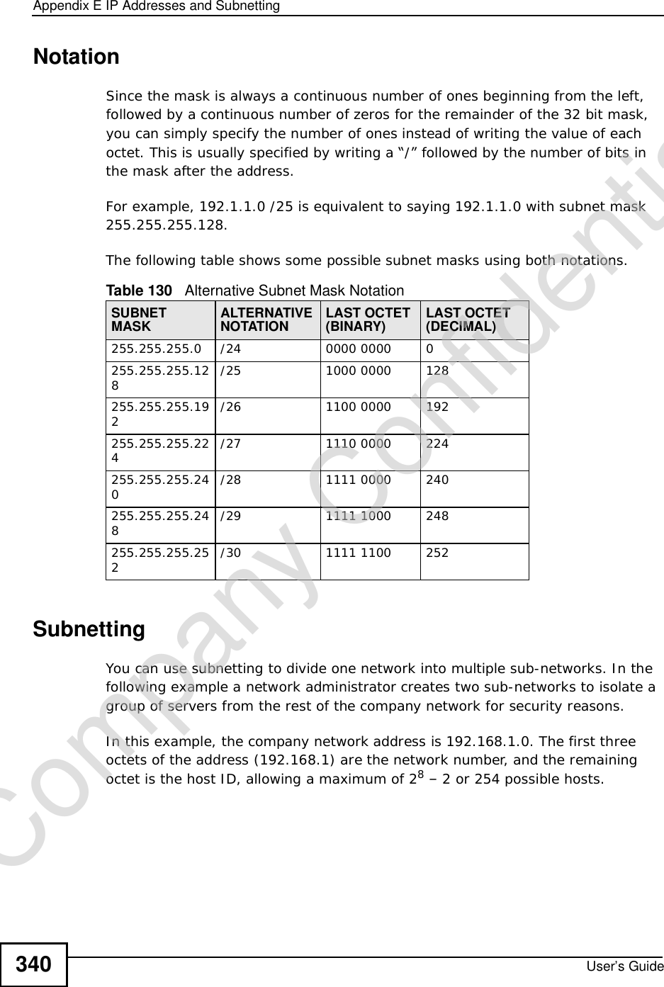
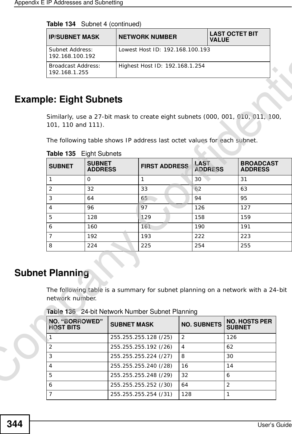
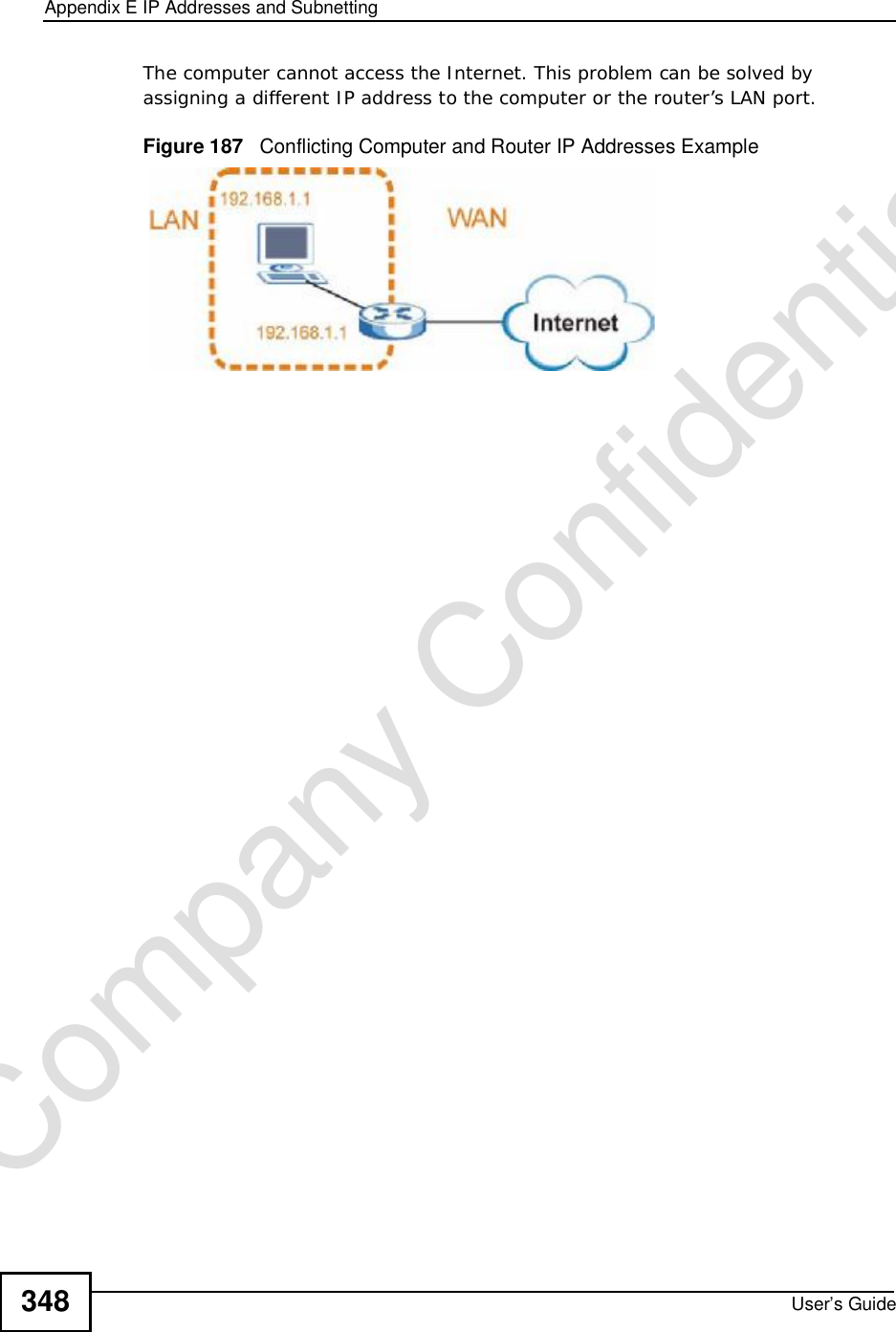
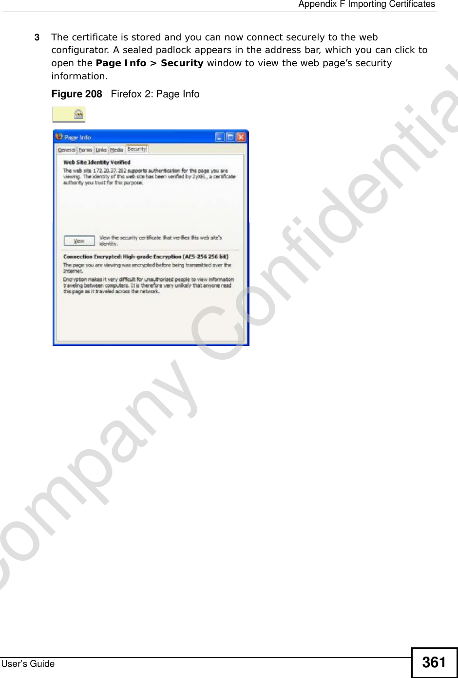
![Chapter 22TroubleshootingUser’s Guide 269•If you changed the IP address (Section 5.2 on page 68), use the new IP address.•If you changed the IP address and have forgotten it, see the troubleshooting suggestions for I forgot the IP address for the WiMAX Device.2Check the hardware connections, and make sure the LEDs are behaving as expected. See the Quick Start Guide and Section 1.2.1 on page 34.3Make sure your Internet browser does not block pop-up windows and has JavaScript and Java enabled. See Appendix D on page 327.4If there is a DHCP server on your network, make sure your computer is using a dynamic IP address. Your WiMAX Device is a DHCP server by default.If there is no DHCP server on your network, make sure your computer’s IP address is in the same subnet as the WiMAX Device. See Appendix E on page 337.5Reset the WiMAX Device to its factory defaults, and try to access the WiMAX Device with the default IP address. See Section 11.6 on page 143.6If the problem continues, contact the network administrator or vendor, or try one of the advanced suggestions.Advanced Suggestions•Try to access the WiMAX Device using another service, such as Telnet. If you can access the WiMAX Device, check the remote management settings and firewall rules to find out why the WiMAX Device does not respond to HTTP.•If your computer is connected wirelessly, use a computer that is connected to a LAN/ETHERNET port.I can see the Login screen, but I cannot log in to the WiMAX Device.1Make sure you have entered the user name and password correctly. The default user name is admin, and the default password is 1234. These fields are case-sensitive, so make sure [Caps Lock] is not on.2You cannot log in to the web configurator while someone is using Telnet to access the WiMAX Device. Log out of the WiMAX Device in the other session, or ask the person who is logged in to log out.3Disconnect and re-connect the power adapter or cord to the WiMAX Device.4If this does not work, you have to reset the WiMAX Device to its factory defaults. See Section 11.5 on page 142.Company Confidential](https://usermanual.wiki/ZyXEL-Communications/MAX306.Manual-Part-2/User-Guide-1135856-Page-19.png)
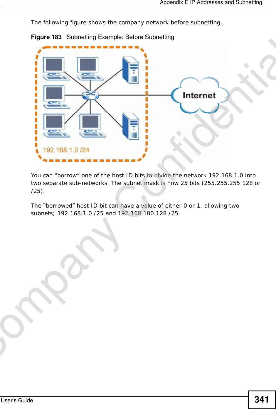
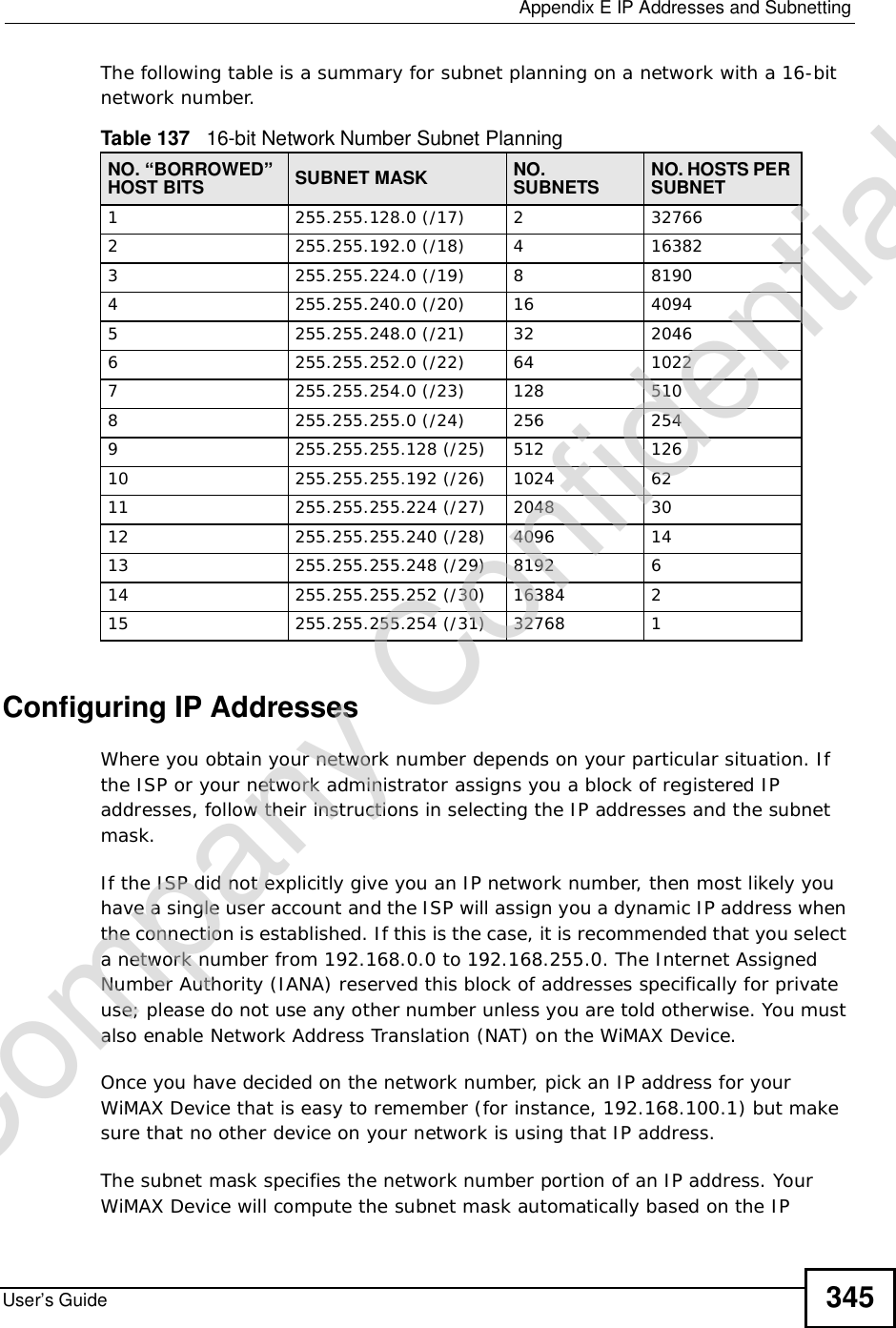
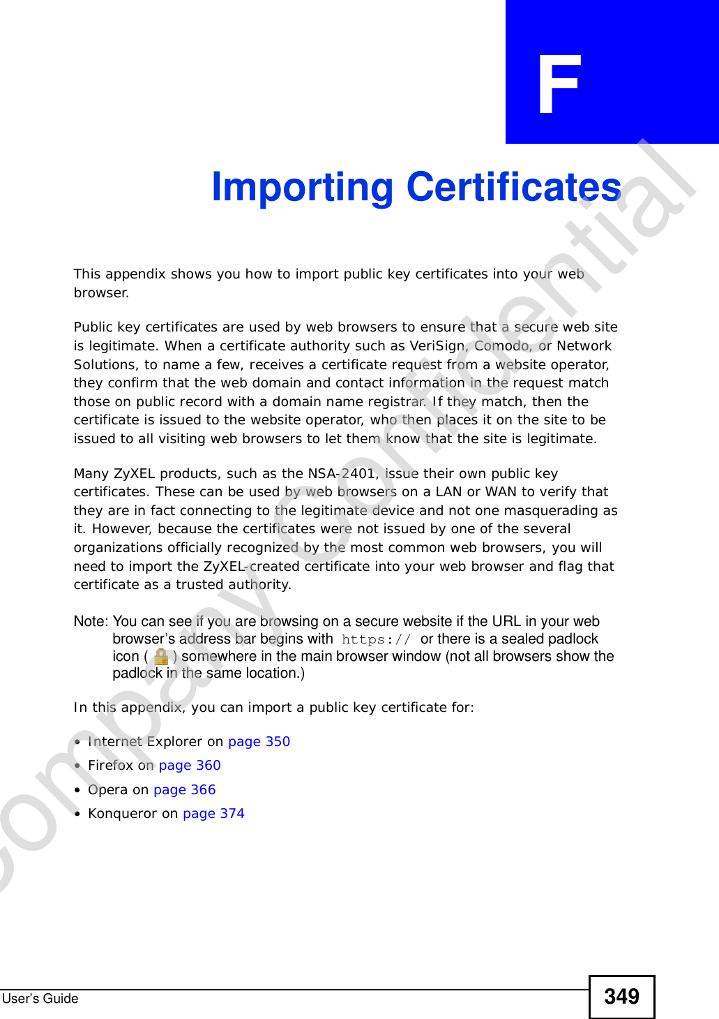
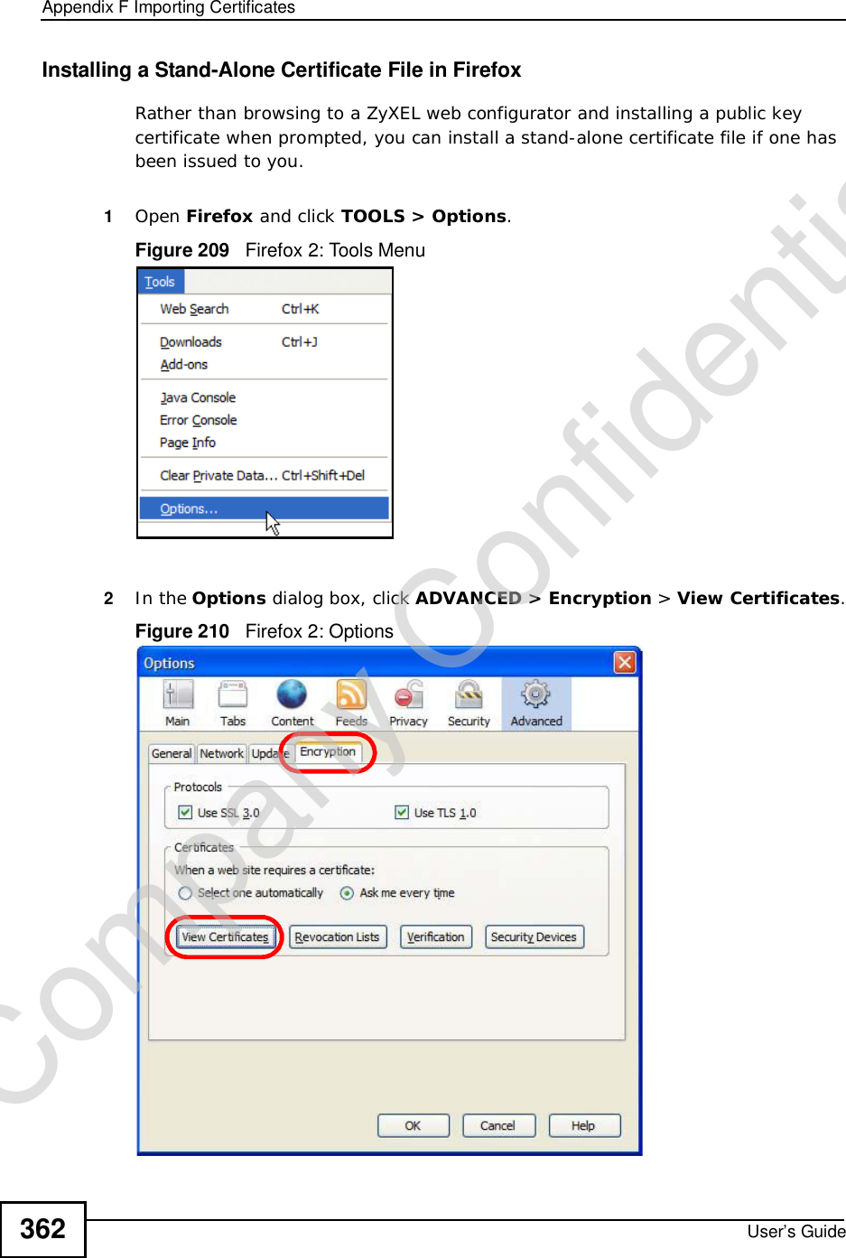
![Chapter 22TroubleshootingUser’s Guide270I cannot Telnet to the WiMAX Device.See the troubleshooting suggestions for I cannot see or access the Login screen in the web configurator. Ignore the suggestions about your browser.22.3 Internet AccessI cannot access the Internet.1Check the hardware connections, and make sure the LEDs are behaving as expected. See the Quick Start Guide and Section 1.2.1 on page 34.2Make sure you entered your ISP account information correctly in the wizard. These fields are case-sensitive, so make sure [Caps Lock] is not on.3Check your security settings. In the web configurator, go to the Status screen. Click the WiMAX Profile link in the Summary box and make sure that you are using the correct security settings for your Internet account.4Check your WiMAX settings. The WiMAX Device may have been set to search the wrong frequencies for a wireless connection. In the web configurator, go to the Status screen. Click the WiMAX Site Information link in the Summary box and ensure that the values are correct. If the values are incorrect, enter the correct frequency settings in the ADVANCED > WAN Configuration > WiMAX Configuration screen. If you are unsure of the correct values, contact your service provider.5If you are trying to access the Internet wirelessly, make sure the wireless settings in the wireless client are the same as the settings in the AP.6Disconnect all the cables from your WiMAX Device, and follow the directions in the Quick Start Guide again.7If the problem continues, contact your ISP.I cannot access the Internet any more. I had access to the Internet (with the WiMAX Device), but my Internet connection is not available any more.Company Confidential](https://usermanual.wiki/ZyXEL-Communications/MAX306.Manual-Part-2/User-Guide-1135856-Page-20.png)

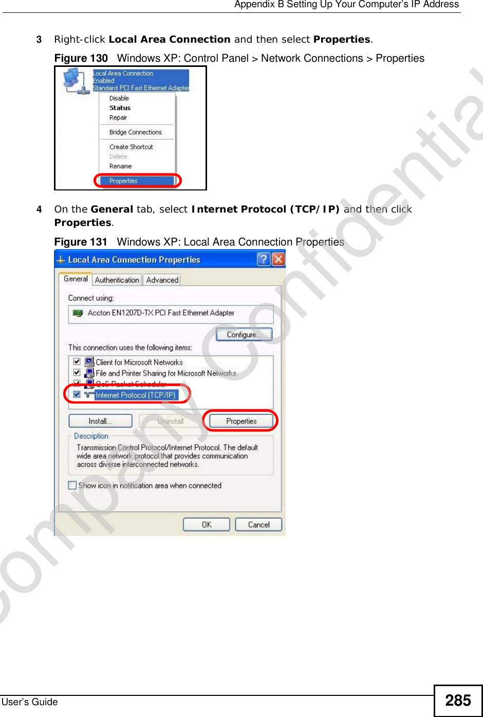
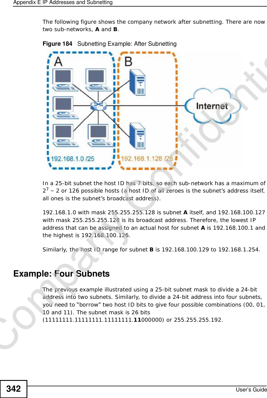
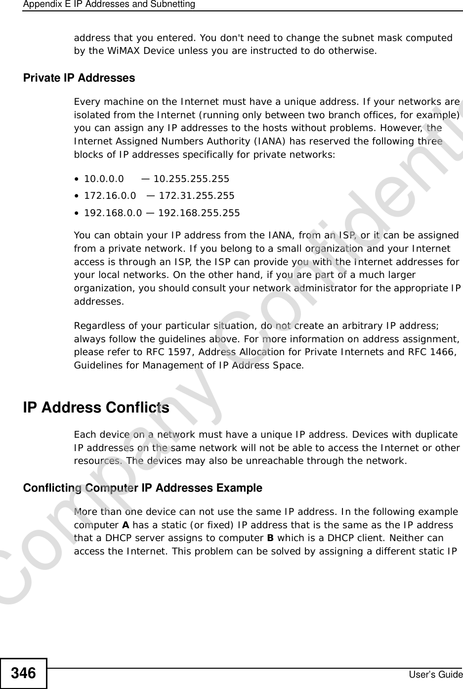
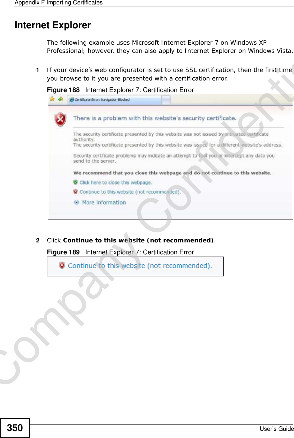
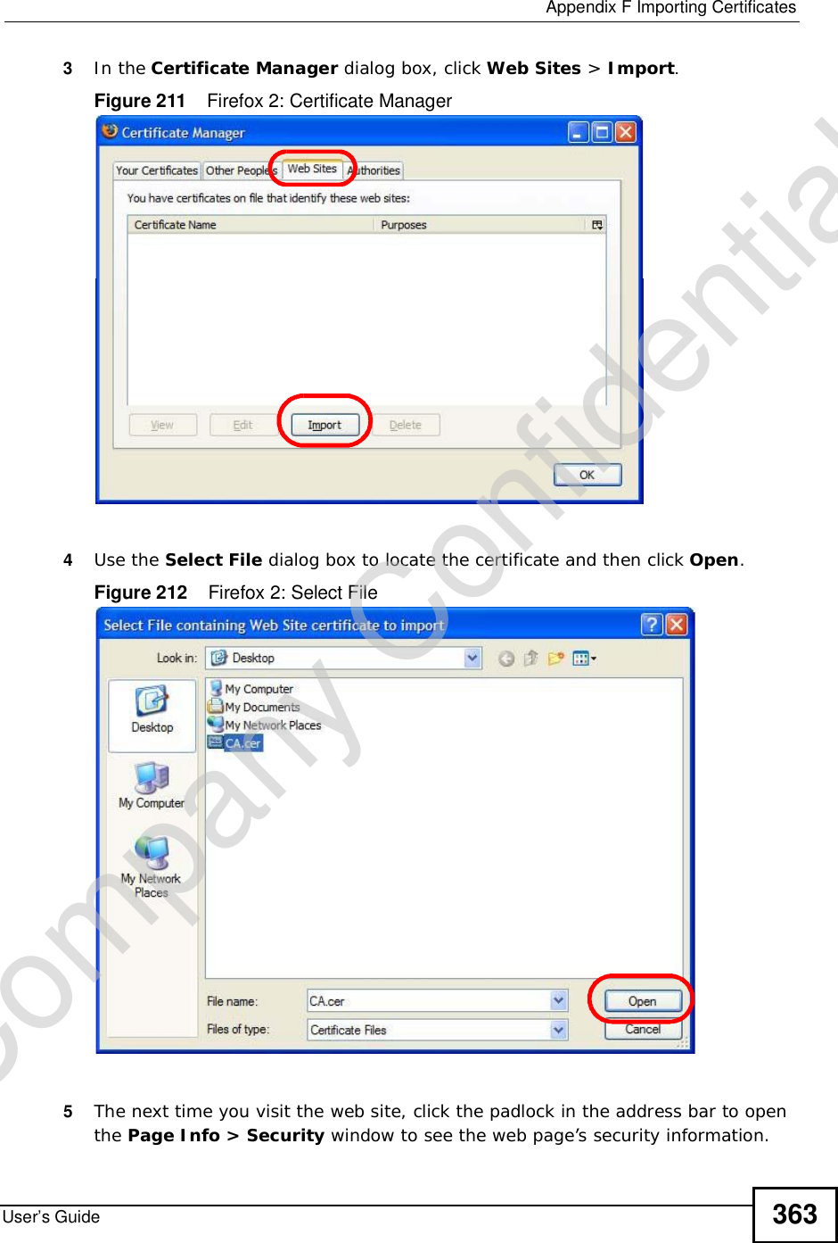
![Appendix BSetting Up Your Computer’s IP AddressUser’s Guide2865The Internet Protocol TCP/IP Properties window opens.Figure 132 Windows XP: Internet Protocol (TCP/IP) Properties6Select Obtain an IP address automatically if your network administrator or ISP assigns your IP address dynamically.Select Use the following IP Address and fill in the IP address,Subnet mask,and Default gateway fields if you have a static IP address that was assigned to you by your network administrator or ISP. You may also have to enter a Preferred DNS server and an AlternateDNS server, if that information was provided.7Click OK to close the Internet Protocol (TCP/IP) Properties window.Click OK to close the Local Area Connection Properties window.Verifying Settings1Click Start > All Programs > Accessories > Command Prompt.2In the Command Prompt window, type "ipconfig" and then press [ENTER]. You can also go to Start > Control Panel > Network Connections, right-click a network connection, click Status and then click the Support tab to view your IP address and connection information.Company Confidential](https://usermanual.wiki/ZyXEL-Communications/MAX306.Manual-Part-2/User-Guide-1135856-Page-36.png)
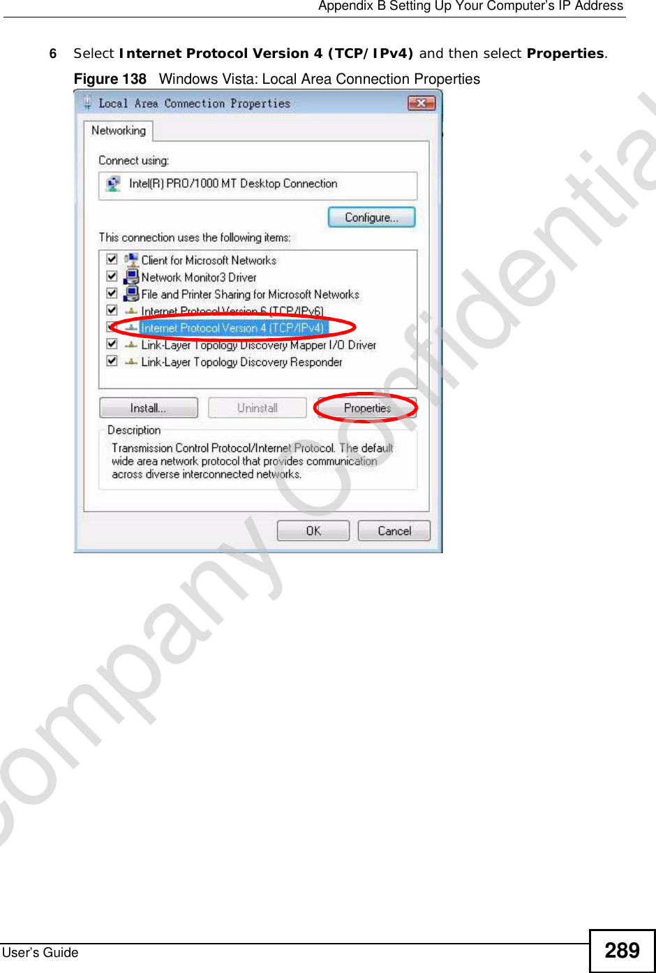
![Appendix BSetting Up Your Computer’s IP AddressUser’s Guide2907The Internet Protocol Version 4 (TCP/IPv4) Properties window opens.Figure 139 Windows Vista: Internet Protocol Version 4 (TCP/IPv4) Properties8Select Obtain an IP address automatically if your network administrator or ISP assigns your IP address dynamically.Select Use the following IP Address and fill in the IP address,Subnet mask,and Default gateway fields if you have a static IP address that was assigned to you by your network administrator or ISP. You may also have to enter a Preferred DNS server and an AlternateDNS server, if that information was provided.Click Advanced.9Click OK to close the Internet Protocol (TCP/IP) Properties window.Click OK to close the Local Area Connection Properties window.Verifying Settings1Click Start > All Programs > Accessories > Command Prompt.2In the Command Prompt window, type "ipconfig" and then press [ENTER]. You can also go to Start > Control Panel > Network Connections, right-click a network connection, click Status and then click the Support tab to view your IP address and connection information.Company Confidential](https://usermanual.wiki/ZyXEL-Communications/MAX306.Manual-Part-2/User-Guide-1135856-Page-40.png)