ZyXEL Communications MAX306 2.5GHz MIMO Outdoor CPE User Manual MAX 306HW2 Series UG v1 ed1 2009 06 29
ZyXEL Communications Corporation 2.5GHz MIMO Outdoor CPE MAX 306HW2 Series UG v1 ed1 2009 06 29
Contents
- 1. Manual Part 1
- 2. Manual Part 2
Manual Part 2
Chapter 20The UPnP Screen
User’s Guide 251
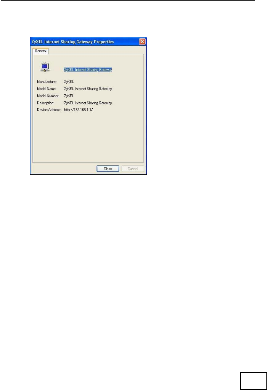
6Right-click on the icon for your WiMAX Device and select Properties. A properties
window displays with basic information about the WiMAX Device.
Figure 121 Network Connections: My Network Places: Properties: Example
Company Confidential

Chapter 20The UPnP Screen
User’s Guide
252
Company Confidential

User’s Guide 253
CHAPTER 21
The Status Screen
21.1 Overview
Use this screen to view a complete summary of your WiMAX Device connection
status.
21.2 Status Screen
Click the STATUS icon in the navigation bar to go to this screen, where you can
view the current status of the device, system resources, interfaces (LAN and
WAN), and SIP accounts. You can also register and un-register SIP accounts as
well as view detailed information from DHCP and statistics from WiMAX, VoIP,
bandwidth management, and traffic.
Figure 122 Status
Company Confidential

Chapter 21The Status Screen
User’s Guide
254
The following tables describe the labels in this screen.
Table 113 Status
LABEL DESCRIPTION
Refresh IntervalSelect how often you want the WiMAX Device to update this screen.
Refresh NowClick this to update this screen immediately.
Device Information
System NameThis field displays the WiMAX Device system name. It is used for
identification.
You can change this in the ADVANCED > System Configuration >
General screen’s System Name field.
Firmware
Version This field displays the current version of the firmware inside the device.
It also shows the date the firmware version was created.
You can change the firmware version by uploading new firmware in
ADVANCED > System Configuration > Firmware.
WAN Information
IP AddressThis field displays the current IP address of the WiMAX Device in the
WAN.
IP Subnet MaskThis field displays the current subnet mask on the WAN.
DHCPThis field displays what DHCP services the WiMAX Device is using in the
WAN. Choices are:
Client - The WiMAX Device is a DHCP client in the WAN. Its IP
address comes from a DHCP server on the WAN.
None - The WiMAX Device is not using any DHCP services in the
WAN. It has a static IP address.
LAN Information
IP AddressThis field displays the current IP address of the WiMAX Device in the
LAN.
IP Subnet MaskThis field displays the current subnet mask in the LAN.
DHCPThis field displays what DHCP services the WiMAX Device is providing to
the LAN. Choices are:
Server - The WiMAX Device is a DHCP server in the LAN. It assigns
IP addresses to other computers in the LAN.
Relay - The WiMAX Device is routing DHCP requests to one or more
DHCP servers. The DHCP server(s) may be on another network.
None - The WiMAX Device is not providing any DHCP services to the
LAN.
You can change this in ADVANCED > LAN Configuration > DHCP
Setup.
WiMAX Information
Operator ID Every WiMAX service provider has a unique Operator ID number, which
is broadcast by each base station it owns. You can only connect to the
Internet through base stations belonging to your service provider’s
network.
BSID This field displays the identification number of the wireless base station
to which the WiMAX Device is connected. Every base station transmits a
unique BSID, which identifies it across the network.
Company Confidential

Chapter 21The Status Screen
User’s Guide 255
Cell ID A base station’s coverage area can be divided into multiple cells. This
field shows the identification number of the cell in which the WiMAX
Device is connected.
Frequency This field displays the radio frequency of the WiMAX Device’s wireless
connection to a base station.
MAC address This field displays the Media Access Control address of the WiMAX
Device. Every network device has a unique MAC address which
identifies it across the network.
WiMAX StateThis field displays the status of the WiMAX Device’s current connection.
•INIT: the WiMAX Device is starting up.
•DL_SYN: The WiMAX Device is unable to connect to a base station.
•RANGING: the WiMAX Device and the base station are transmitting
and receiving information about the distance between them.
Ranging allows the WiMAX Device to use a lower transmission power
level when communicating with a nearby base station, and a higher
transmission power level when communicating with a distant base
station.
•CAP_NEGO: the WiMAX Device and the base station are exchanging
information about their capabilities.
•AUTH: the WiMAX Device and the base station are exchanging
security information.
•REGIST: the WiMAX Device is registering with a RADIUS server.
•OPERATIONAL: the WiMAX Device has successfully registered with
the base station. Traffic can now flow between the WiMAX Device
and the base station.
•IDLE: the WiMAX Device is in power saving mode, but can connect
when a base station alerts it that there is traffic waiting.
Bandwidth This field shows the size of the bandwidth step the WiMAX Device uses
to connect to a base station in megahertz (MHz).
CINR mean This field shows the average Carrier to Interference plus Noise Ratio of
the current connection. This value is an indication of overall radio signal
quality. A higher value indicates a higher signal quality, and a lower
value indicates a lower signal quality.
CINR deviation This field shows the amount of change in the CINR level. This value is
an indication of radio signal stability. A lower number indicates a more
stable signal, and a higher number indicates a less stable signal.
RSSI This field shows the Received Signal Strength Indication. This value is a
measurement of overall radio signal strength. A higher RSSI level
indicates a stronger signal, and a lower RSSI level indicates a weaker
signal.
A strong signal does not necessarily indicate a good signal: a strong
signal may have a low signal-to-noise ratio (SNR).
UL Data Rate This field shows the number of data packets uploaded from the WiMAX
Device to the base station each second.
DL Data Rate This field shows the number of data packets downloaded to the WiMAX
Device from the base station each second.
PER This field shows the Packet Error Rate. The PER is the percentage of
data packets transmitted across the network but not successfully
received.
Table 113 Status (continued)
LABEL DESCRIPTION
Company Confidential

Chapter 21The Status Screen
User’s Guide
256
Tx Power This field shows the output transmission (Tx) level of the WiMAX
Device.
System Status
System UptimeThis field displays how long the WiMAX Device has been running since it
last started up. The WiMAX Device starts up when you plug it in, when
you restart it (ADVANCED > System Configuration > Restart), or
when you reset it.
Current Date/
Time This field displays the current date and time in the WiMAX Device. You
can change this in SETUP > Time Setting.
CPU UsageThis field displays what percentage of the WiMAX Device’s processing
ability is currently being used. The higher the CPU usage, the more
likely the WiMAX Device is to slow down. You can reduce this by
disabling some services, such as DHCP, NAT, or content filtering.
Memory UsageThis field displays what percentage of the WiMAX Device’s memory is
currently used. The higher the memory usage, the more likely the
WiMAX Device is to slow down. Some memory is required just to start
the WiMAX Device and to run the web configurator. You can reduce the
memory usage by disabling some services (see CPU Usage); by
reducing the amount of memory allocated to NAT and firewall rules (you
may have to reduce the number of NAT rules or firewall rules to do so);
or by deleting rules in functions such as incoming call policies, speed
dial entries, and static routes.
IVR UsageThis field displays what percentage of the WiMAX Device’s IVR memory
is currently used. IVR (Interactive Voice Response) refers to the
customizable ring tone and on-hold music you set.
Interface Status
InterfaceThis column displays each interface of the WiMAX Device.
StatusThis field indicates whether or not the WiMAX Device is using the
interface.
For the WAN interface, this field displays Up when the WiMAX Device is
connected to a WiMAX network, and Down when the WiMAX Device is
not connected to a WiMAX network.
For the LAN interface, this field displays Up when the WiMAX Device is
using the interface and Down when the WiMAX Device is not using the
interface.
RateFor the LAN ports this displays the port speed and duplex setting.
For the WAN interface, it displays the downstream and upstream
transmission rate or N/A if the WiMAX Device is not connected to a
base station.
For the WLAN interface, it displays the transmission rate when WLAN is
enabled or N/A when WLAN is disabled.
Summary
Packet
Statistics Click this link to view port status and packet specific statistics.
WiMAX Site
Information Click this link to view details of the radio frequencies used by the
WiMAX Device to connect to a base station.
Table 113 Status (continued)
LABEL DESCRIPTION
Company Confidential

Chapter 21The Status Screen
User’s Guide 257
DHCP TableClick this link to see details of computers to which the WiMAX Device
has given an IP address.
VoIP StatisticsClick this link to view statistics about your VoIP usage.
WiMAX ProfileClick this link to view details of the current wireless security settings.
VoIP Status
AccountThis column displays each SIP account in the WiMAX Device.
RegistrationThis field displays the current registration status of the SIP account.
You have to register SIP accounts with a SIP server to use VoIP.
If the SIP account is already registered with the SIP server,
Click Unregister to delete the SIP account’s registration in the SIP
server. This does not cancel your SIP account, but it deletes the
mapping between your SIP identity and your IP address or domain
name.
The second field displays Registered.
If the SIP account is not registered with the SIP server,
Click Register to have the WiMAX Device attempt to register the SIP
account with the SIP server.
The second field displays the reason the account is not registered.
Inactive - The SIP account is not active. You can activate it in VOICE
> SIP > SIP Settings.
Register Fail - The last time the WiMAX Device tried to register the SIP
account with the SIP server, the attempt failed. The WiMAX Device
automatically tries to register the SIP account when you turn on the
WiMAX Device or when you activate it.
URIThis field displays the account number and service domain of the SIP
account. You can change these in VOICE > SIP > SIP Settings.
Table 113 Status (continued)
LABEL DESCRIPTION
Company Confidential
Chapter 21The Status Screen
User’s Guide
258
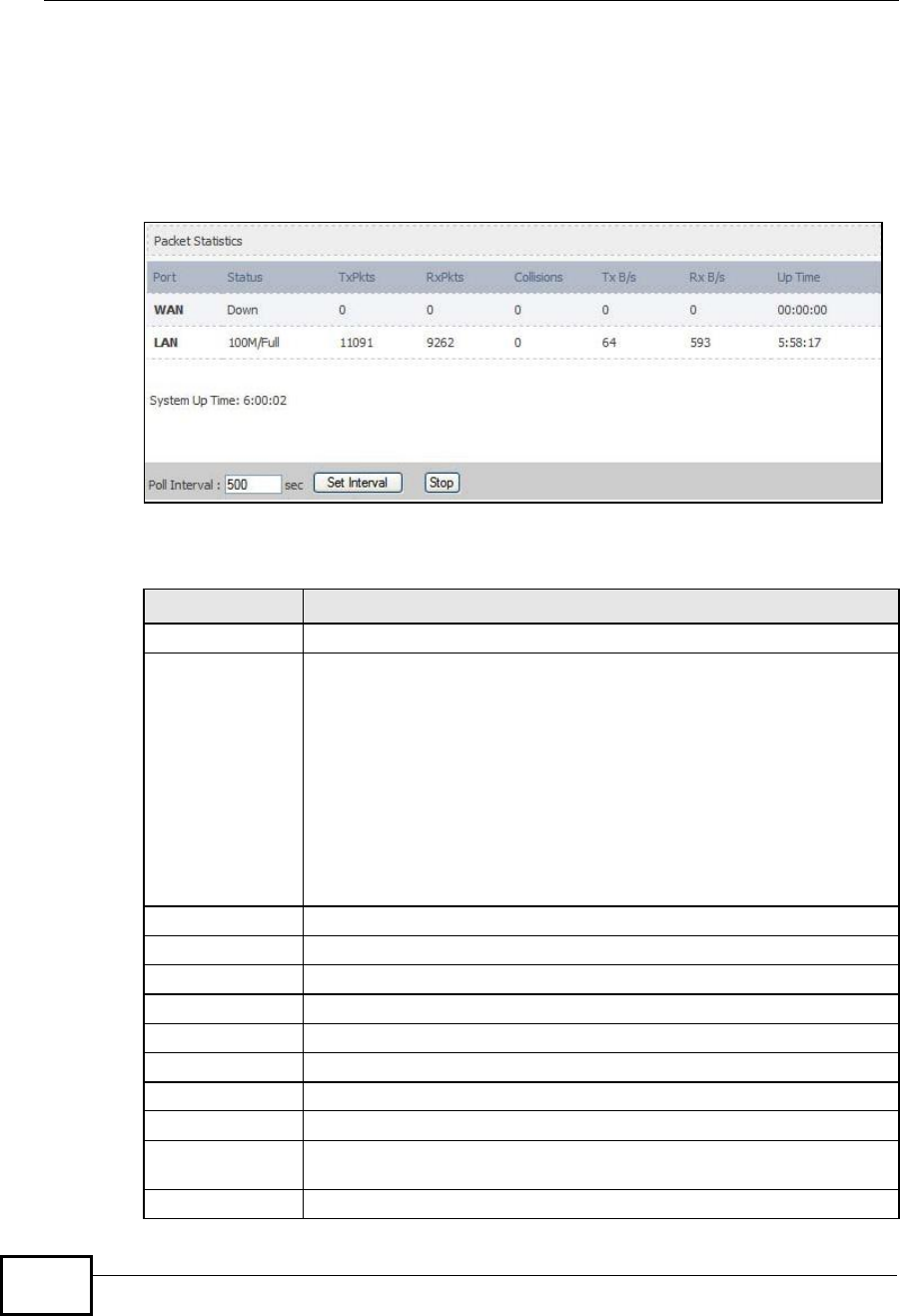
21.2.1 Packet Statistics
Click Status > Packet Statistics to open this screen. This read-only screen
displays information about the data transmission through the WiMAX Device. To
configure these settings, go to the corresponding area in the Advanced screens.
Figure 123 Packet Statistics
The following table describes the fields in this screen.
Table 114 Packet Statistics
LABEL DESCRIPTION
PortThis column displays each interface of the WiMAX Device.
Status This field indicates whether or not the WiMAX Device is using the
interface.
For the WAN interface, this field displays the port speed and duplex
setting when the WiMAX Device is connected to a WiMAX network, and
Down when the WiMAX Device is not connected to a WiMAX network.
For the LAN interface, this field displays the port speed and duplex
setting when the WiMAX Device is using the interface and Down when
the WiMAX Device is not using the interface.
For the WLAN interface, it displays the transmission rate when WLAN
is enabled or Down when WLAN is disabled.
TxPkts This field displays the number of packets transmitted on this interface.
RxPkts This field displays the number of packets received on this interface.
Collisions This field displays the number of collisions on this port.
Tx B/s This field displays the number of bytes transmitted in the last second.
Rx B/s This field displays the number of bytes received in the last second.
Up Time This field displays the elapsed time this interface has been connected.
System up Time This is the elapsed time the system has been on.
Poll Interval(s) Type the time interval for the browser to refresh system statistics.
Set Interval Click this button to apply the new poll interval you entered in the Poll
Interval field above.
Stop Click this button to halt the refreshing of the system statistics.
Company Confidential
Chapter 21The Status Screen
User’s Guide 259
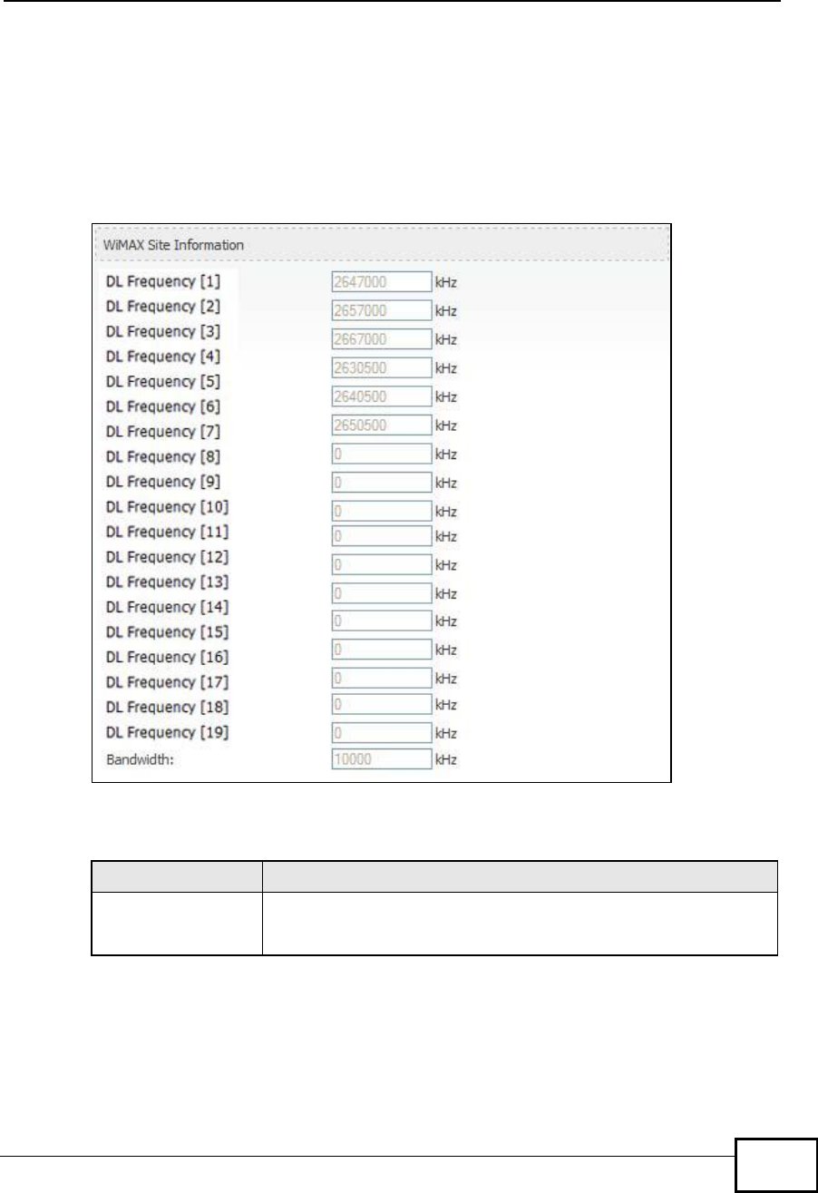
21.2.2 WiMAX Site Information
Click Status > WiMAX Site Information to open this screen. This read-only
screen shows WiMAX frequency information for the WiMAX Device. These settings
can be configured in the ADVANCED > WAN Configuration > WiMAX
Configuration screen.
Figure 124 WiMAX Site Information
The following table describes the labels in this screen.
Table 115 WiMAX Site Information
LABEL DESCRIPTION
DL Frequency
[0] ~ [19]
These fields show the downlink frequency settings in kilohertz
(kHz). These settings determine how the WiMAX Device searches
for an available wireless connection.
Company Confidential
Chapter 21The Status Screen
User’s Guide
260
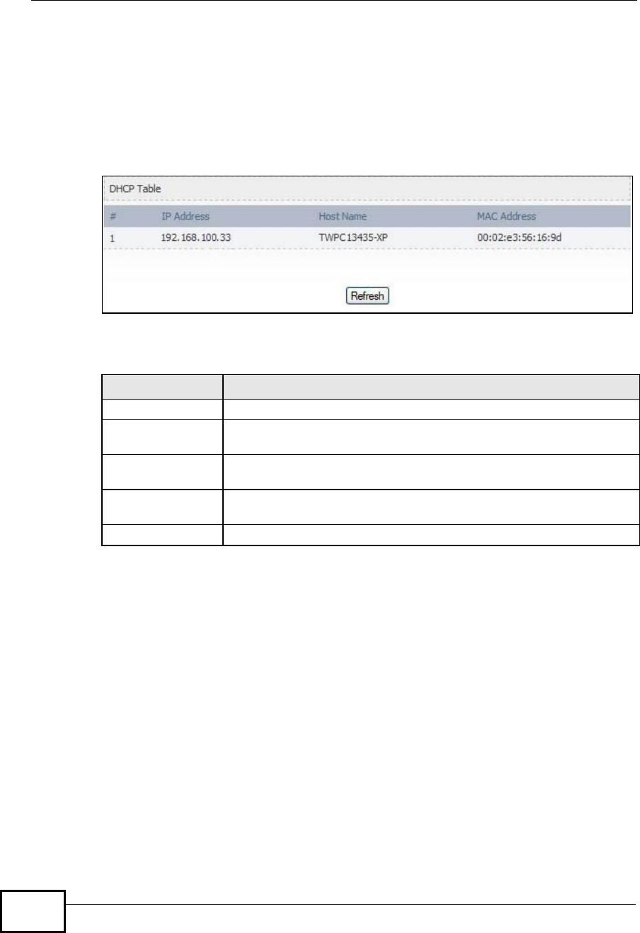
21.2.3 DHCP Table
Click Status > DHCP Table to open this screen. This read-only screen shows the
IP addresses, Host Names and MAC addresses of the devices currently connected
to the WiMAX Device. These settings can be configured in the ADVANCED > LAN
Configuration > DHCP Setup screen.
Figure 125 DHCP Table
Each field is described in the following table.
Table 116 DHCP Table
LABEL DESCRIPTION
#The number of the item in this list.
IP AddressThis field displays the IP address the WiMAX Device assigned to a
computer in the network.
Host NameThis field displays the system name of the computer to which the
WiMAX Device assigned the IP address.
MAC AddressThis field displays the MAC address of the computer to which the
WiMAX Device assigned the IP address.
RefreshClick this button to update the table data.
Company Confidential
Chapter 21The Status Screen
User’s Guide 261
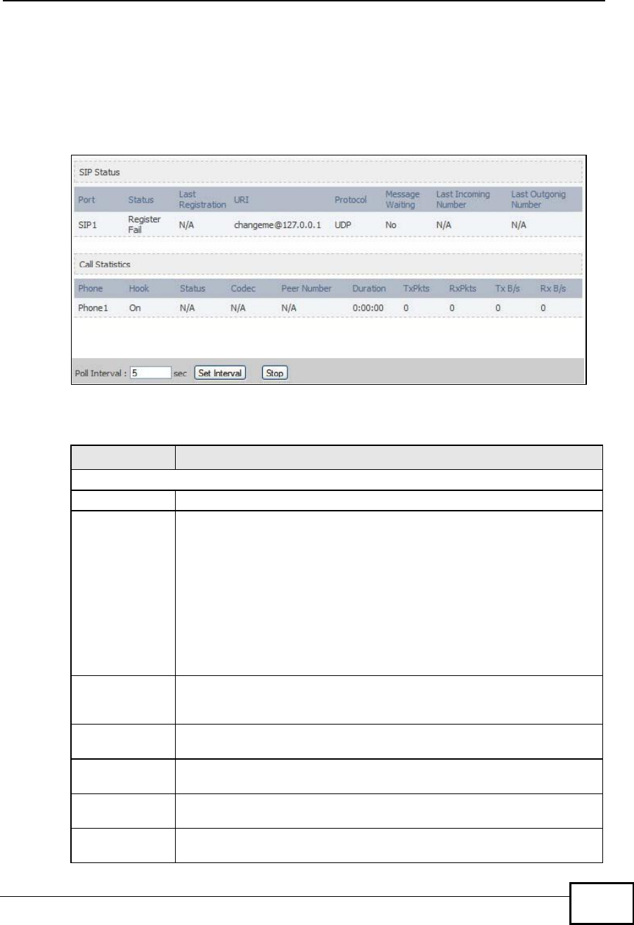
21.2.4 VoIP Statistics
Click Status > DHCP Table to open this screen. This read-only screen shows SIP
registration information, status of calls and VoIP traffic statistics. These settings
can be configured in the VOICE > Service Configuration > SIP Setting screen.
Figure 126 VoIP Statistics
Each field is described in the following table.
Table 117 VoIP Statistics
LABEL DESCRIPTION
SIP Status
PortThis column displays each SIP account in the WiMAX Device.
StatusThis field displays the current registration status of the SIP account.
You can change this in the Status screen.
Registered - The SIP account is registered with a SIP server.
Register Fail - The last time the WiMAX Device tried to register the SIP
account with the SIP server, the attempt failed. The WiMAX Device
automatically tries to register the SIP account when you turn on the
WiMAX Device or when you activate it.
Inactive - The SIP account is not active. You can activate it in VOICE
> SIP > SIP Settings.
Last
Registration This field displays the last time you successfully registered the SIP
account. It displays N/A if you never successfully registered this
account.
URIThis field displays the account number and service domain of the SIP
account. You can change these in VOICE > SIP > SIP Settings.
ProtocolThis field displays the transport protocol the SIP account uses. SIP
accounts always use UDP.
Message
Waiting This field indicates whether or not there are any messages waiting for
the SIP account.
Last Incoming
Number This field displays the last number that called the SIP account. It
displays N/A if no number has ever dialed the SIP account.
Company Confidential

Chapter 21The Status Screen
User’s Guide
262
Last Outgoing
Number This field displays the last number the SIP account called. It displays
N/A if the SIP account has never dialed a number.
Call Statistics
PhoneThis field displays the WiMAX Device’s phone port number.
HookThis field indicates whether the phone is on the hook or off the hook.
On - The phone is hanging up or already hung up.
Off - The phone is dialing, calling, or connected.
StatusThis field displays the current state of the phone call.
N/A - There are no current VoIP calls, incoming calls or outgoing calls
being made.
DIAL - The callee’s phone is ringing.
RING - The phone is ringing for an incoming VoIP call.
Process - There is a VoIP call in progress.
DISC - The callee’s line is busy, the callee hung up or your phone was
left off the hook.
CodecThis field displays what voice codec is being used for a current VoIP call
through a phone port.
Peer NumberThis field displays the SIP number of the party that is currently engaged
in a VoIP call through a phone port.
DurationThis field displays how long the current call has lasted.
Tx PktsThis field displays the number of packets the WiMAX Device has
transmitted in the current call.
Rx PktsThis field displays the number of packets the WiMAX Device has
received in the current call.
Tx B/sThis field displays how quickly the WiMAX Device has transmitted
packets in the current call. The rate is the average number of bytes
transmitted per second.
Rx B/sThis field displays how quickly the WiMAX Device has received packets
in the current call. The rate is the average number of bytes transmitted
per second.
Poll Interval(s)Enter how often you want the WiMAX Device to update this screen, and
click Set Interval.
Set IntervalClick this to make the WiMAX Device update the screen based on the
amount of time you specified in Poll Interval.
StopClick this to make the WiMAX Device stop updating the screen.
Table 117 VoIP Statistics
LABEL DESCRIPTION
Company Confidential
Chapter 21The Status Screen
User’s Guide 263
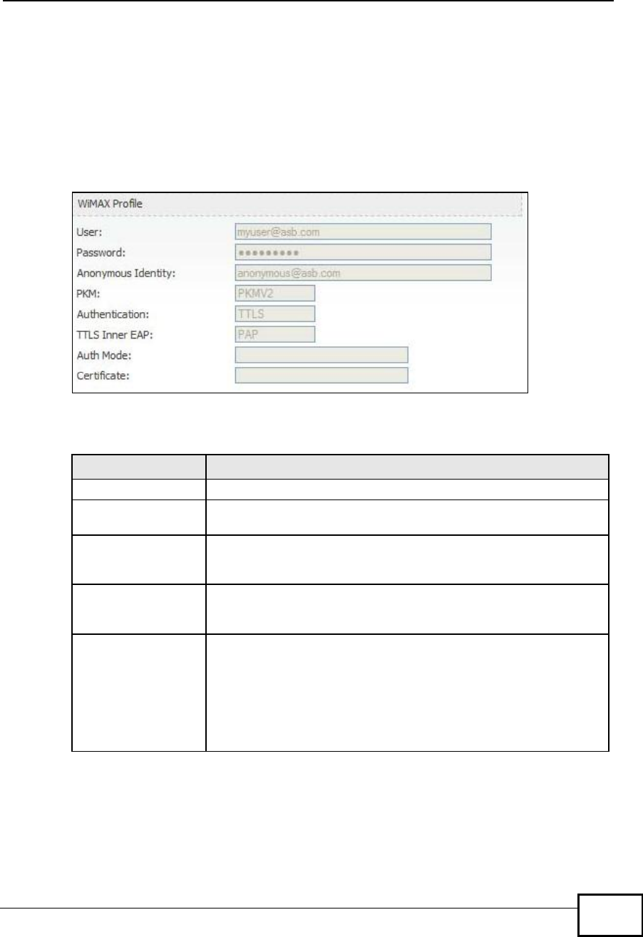
21.2.5 WiMAX Profile
Click Status > WiMAX Profile to open this screen. This read-only screen displays
information about the security settings you are using. To configure these settings,
go to the ADVANCED > WAN Configuration > Internet Connection screen.
Note: Not all WiMAX Device models have all the fields shown here.
Figure 127 WiMAX Profile
The following table describes the labels in this screen.
Table 118 The WiMAX Profile Screen
LABEL DESCRIPTION
UserThis is the username for your Internet access account.
PasswordThis is the password for your Internet access account. The
password displays as a row of asterisks for security purposes.
Anonymous IdentityThis is the anonymous identity provided by your Internet Service
Provider. Anonymous identity (also known as outer identity) is
used with EAP-TTLS encryption.
PKMThis field displays the Privacy Key Management version number.
PKM provides security between the WiMAX Device and the base
station. See the WiMAX security appendix for more information.
AuthenticationThis field displays the user authentication method. Authentication
is the process of confirming the identity of a user (by means of a
username and password, for example).
EAP-TTLS allows an MS/SS and a base station to establish a
secure link (or ‘tunnel’) with an AAA (Authentication, Authorization
and Accounting) server in order to exchange authentication
information. See the WiMAX security appendix for more details.
Company Confidential

Chapter 21The Status Screen
User’s Guide
264
TTLS Inner EAPThis field displays the type of secondary authentication method.
Once a secure EAP-TTLS connection is established, the inner EAP
is the protocol used to exchange security information between the
mobile station, the base station and the AAA server to
authenticate the mobile station. See the WiMAX security appendix
for more details.
The WiMAX Device supports the following inner authentication
types:
•CHAP (Challenge Handshake Authentication Protocol)
•MSCHAP (Microsoft CHAP)
•MSCHAPV2 (Microsoft CHAP version 2)
•PAP (Password Authentication Protocol)
Auth ModeThis is the authentication mode. The WiMAX Device supports the
following authentication modes:
•User Only
•Device Only with Cert
•Certs and User Authentication
CertificateThis is the security certificate the WiMAX Device uses to
authenticate the AAA server, if one is available.
Table 118 The WiMAX Profile Screen (continued)
LABEL DESCRIPTION
Company Confidential

265
PART VI
Troubleshooting
and Specifications
Troubleshooting (267)
Product Specifications (275)
Company Confidential

266
Company Confidential

User’s Guide 267
CHAPTER 22
Troubleshooting
This chapter offers some suggestions to solve problems you might encounter. The
potential problems are divided into the following categories:
•Power, Hardware Connections, and LEDs
•WiMAX Device Access and Login
•Internet Access
•Phone Calls and VoIP
•Reset the WiMAX Device to Its Factory Defaults
22.1 Power, Hardware Connections, and LEDs
The WiMAX Device does not turn on. None of the LEDs turn on.
1Make sure you are using the power adapter or cord included with the WiMAX
Device.
2Make sure the power adapter or cord is connected to the WiMAX Device and
plugged in to an appropriate power source. Make sure the power source is turned
on.
3Disconnect and re-connect the power adapter or cord to the WiMAX Device.
4If the problem continues, contact the vendor.
One of the LEDs does not behave as expected.
1Make sure you understand the normal behavior of the LED. See Section 1.2.1 on
page 34 for more information.
Company Confidential

Chapter 22Troubleshooting
User’s Guide
268
2Check the hardware connections. See the Quick Start Guide.
3Inspect your cables for damage. Contact the vendor to replace any damaged
cables.
4Disconnect and re-connect the power adapter to the WiMAX Device.
5If the problem continues, contact the vendor.
22.2 WiMAX Device Access and Login
I forgot the IP address for the WiMAX Device.
1The default IP address is http://192.168.100.1.
2If you changed the IP address and have forgotten it, you might get the IP address
of the WiMAX Device by looking up the IP address of the default gateway for your
computer. To do this in most Windows computers, click Start > Run, enter cmd,
and then enter ipconfig. The IP address of the Default Gateway might be the IP
address of the WiMAX Device (it depends on the network), so enter this IP address
in your Internet browser.
3If this does not work, you have to reset the WiMAX Device to its factory defaults.
See Section 22.1 on page 267.
I forgot the password.
1The default password is 1234.
2If this does not work, you have to reset the WiMAX Device to its factory defaults.
See Section 11.5 on page 142.
I cannot see or access the Login screen in the web configurator.
1Make sure you are using the correct IP address.
•The default IP address is http://192.168.100.1.
Company Confidential

Chapter 22Troubleshooting
User’s Guide 269
•If you changed the IP address (Section 5.2 on page 68), use the new IP
address.
•If you changed the IP address and have forgotten it, see the troubleshooting
suggestions for I forgot the IP address for the WiMAX Device.
2Check the hardware connections, and make sure the LEDs are behaving as
expected. See the Quick Start Guide and Section 1.2.1 on page 34.
3Make sure your Internet browser does not block pop-up windows and has
JavaScript and Java enabled. See Appendix D on page 327.
4If there is a DHCP server on your network, make sure your computer is using a
dynamic IP address. Your WiMAX Device is a DHCP server by default.
If there is no DHCP server on your network, make sure your computer’s IP
address is in the same subnet as the WiMAX Device. See Appendix E on page 337.
5Reset the WiMAX Device to its factory defaults, and try to access the WiMAX
Device with the default IP address. See Section 11.6 on page 143.
6If the problem continues, contact the network administrator or vendor, or try one
of the advanced suggestions.
Advanced Suggestions
•Try to access the WiMAX Device using another service, such as Telnet. If you
can access the WiMAX Device, check the remote management settings and
firewall rules to find out why the WiMAX Device does not respond to HTTP.
•If your computer is connected wirelessly, use a computer that is connected to a
LAN/ETHERNET port.
I can see the Login screen, but I cannot log in to the WiMAX Device.
1Make sure you have entered the user name and password correctly. The default
user name is admin, and the default password is 1234. These fields are case-
sensitive, so make sure [Caps Lock] is not on.
2You cannot log in to the web configurator while someone is using Telnet to access
the WiMAX Device. Log out of the WiMAX Device in the other session, or ask the
person who is logged in to log out.
3Disconnect and re-connect the power adapter or cord to the WiMAX Device.
4If this does not work, you have to reset the WiMAX Device to its factory defaults.
See Section 11.5 on page 142.
Company Confidential

Chapter 22Troubleshooting
User’s Guide
270
I cannot Telnet to the WiMAX Device.
See the troubleshooting suggestions for I cannot see or access the Login screen in
the web configurator. Ignore the suggestions about your browser.
22.3 Internet Access
I cannot access the Internet.
1Check the hardware connections, and make sure the LEDs are behaving as
expected. See the Quick Start Guide and Section 1.2.1 on page 34.
2Make sure you entered your ISP account information correctly in the wizard.
These fields are case-sensitive, so make sure [Caps Lock] is not on.
3Check your security settings. In the web configurator, go to the Status screen.
Click the WiMAX Profile link in the Summary box and make sure that you are
using the correct security settings for your Internet account.
4Check your WiMAX settings. The WiMAX Device may have been set to search the
wrong frequencies for a wireless connection. In the web configurator, go to the
Status screen. Click the WiMAX Site Information link in the Summary box and
ensure that the values are correct. If the values are incorrect, enter the correct
frequency settings in the ADVANCED > WAN Configuration > WiMAX
Configuration screen. If you are unsure of the correct values, contact your
service provider.
5If you are trying to access the Internet wirelessly, make sure the wireless settings
in the wireless client are the same as the settings in the AP.
6Disconnect all the cables from your WiMAX Device, and follow the directions in the
Quick Start Guide again.
7If the problem continues, contact your ISP.
I cannot access the Internet any more. I had access to the Internet (with the
WiMAX Device), but my Internet connection is not available any more.
Company Confidential

Chapter 22Troubleshooting
User’s Guide 271
1Check the hardware connections, and make sure the LEDs are behaving as
expected. See the Quick Start Guide and Section 1.2.1 on page 34.
2Disconnect and re-connect the power adapter to the WiMAX Device.
3If the problem continues, contact your ISP.
The Internet connection is slow or intermittent.
1The quality of the WiMAX Device’s wireless connection to the base station may be
poor. Poor signal reception may be improved by moving the WiMAX Device away
from thick walls and other obstructions, or to a higher floor in your building.
2There may be radio interference caused by nearby electrical devices such as
microwave ovens and radio transmitters. Move the WiMAX Device away or switch
the other devices off. Weather conditions may also affect signal quality.
3As well as having an external antenna connector, the MAX-210HW2 is equipped
with an internal directional antenna. If you know the location of the base station,
orient the front of the WiMAX Device (the side with the LEDs) towards the base
station. If you do not know the location of the base station, experiment by moving
the WiMAX Device while observing the Strength Indicator LEDs for an increase
in received signal strength. The MAX-200HW2 and MAX-230HW2 do not have
internal antennas.
4There might be a lot of traffic on the network. Look at the LEDs, and check Section
1.2.1 on page 34. If the WiMAX Device is sending or receiving a lot of information,
try closing some programs that use the Internet, especially peer-to-peer
applications.
5Disconnect and re-connect the power adapter to the WiMAX Device.
6If the problem continues, contact the network administrator or vendor, or try one
of the advanced suggestions.
The Internet connection disconnects.
1Check your WiMAX link and signal strength using the WiMAX Link and Strength
Indicator LEDs on the device.
2Contact your ISP if the problem persists.
Company Confidential

Chapter 22Troubleshooting
User’s Guide
272
22.4 Phone Calls and VoIP
The telephone port won’t work or the telephone lacks a dial tone.
1Check the telephone connections and telephone wire.
2Make sure you have the VOICE > Service Configuration > SIP Settings
screen properly configured (Chapter 12 on page 147).
I can access the Internet, but cannot make VoIP calls.
1Make sure you have the VOICE > Service Configuration > SIP Settings
screen properly configured (Chapter 12 on page 147).
2The VoIP LED should come on. Make sure that your telephone is connected to the
VoIP port (see the Quick Start Guide for information on connecting telephone
cables to the these ports).
3You can also check the VoIP status in the Status screen.
4If the VoIP settings are correct, use speed dial to make peer-to-peer calls. If you
cannot make a call using speed dial, there may be something wrong with the SIP
server. Contact your VoIP service provider.
Problems With Multiple SIP Accounts
You can set up two SIP accounts on your WiMAX Device. By default your WiMAX
Device uses SIP account 1 for outgoing calls, and it uses SIP accounts 1 and 2 for
incoming calls. With this setting, you always use SIP account 1 for your outgoing
calls and you cannot distinguish which SIP account the calls are coming in
through. If you want to control the use of different dialing plans for accounting
purposes or other reasons, you need to configure your phone port in order to
control which SIP account you are using when placing or receiving calls.
Company Confidential

Chapter 22Troubleshooting
User’s Guide 273
22.5 Reset the WiMAX Device to Its Factory
Defaults
If you reset the WiMAX Device, you lose all of the changes you have made. The
WiMAX Device re-loads its default settings, and the password resets to 1234. You
have to make all of your changes again.
You will lose all of your changes when you push the Reset button.
To reset the WiMAX Device,
1Make sure the Power LED is on and not blinking.
2Press and hold the Reset button for five to ten seconds. Release the Reset button
when the Power LED begins to blink. The default settings have been restored.
If the WiMAX Device restarts automatically, wait for the WiMAX Device to finish
restarting, and log in to the web configurator. The password is “1234”.
If the WiMAX Device does not restart automatically, disconnect and reconnect the
WiMAX Device’s power. Then, follow the directions above again.
22.5.1 Pop-up Windows, JavaScripts and Java Permissions
Please see Appendix D on page 327.
Company Confidential

Chapter 22Troubleshooting
User’s Guide
274
Company Confidential

User’s Guide 275
CHAPTER 23
Product Specifications
This chapter gives details about your WiMAX Device’s hardware and firmware
features.
Table 119 IDU Hardware Specifications
FEATUREDESCRIPTION
Device NameMAX-306HW2-IDU
Dimension (W x D x H)216 mm x 164 mm x 52 mm
Weight450 g
Power48V DC, 1.25A
Ethernet Ports4 RJ-45 Ethernet ports
Phone Ports2 RJ-11 phone ports
Power over Ethernet (PoE)Provides Power over Ethernet via PoE port.
Wireless LAN AntennaExternal dipole, 2dBi gain.
Wireless LAN Antenna
Connector 1 R-SMA connector for external wireless LAN antenna
Operation Environmental Temperature: 0oC ~ 45oC
Humidity: 10% ~ 90% RH
Storage Environmental Temperature: -25oC ~ 55oC
Humidity: 10% ~ 95% RH
CertificationSafety
CSA 60950-1-07
EMI & EMS
CE certification & WiMAX Forum Wave II Compliance
Table 120 Indoor Wireless LAN Specification
FEATUREDESCRIPTION
Standard IEEE802.11b/g compliant
Transmit Output Power802.11b: 17 ± 2dBm @11Mbps (Typical 18dBm)
802.11g: 14 ± 2dBm @54Mbps (Typical 15dBm)
Receiver Sensitivity -70dBm @54M, -85dBm @11M
Company Confidential

Chapter 23Product Specifications
User’s Guide
276
Table 121 ODU Hardware Specifications
FEATUREDESCRIPTION
Device NameMAX-306
MAX-316
Dimension (W x D x H)231 mm x 236 mm x 69.6 mm
Weight4 kg including the mount kits
Data/Power PortIDU end: RJ-45 Connector
ODU end: RJ-45 Connector
WiMAX AntennaMAX-306: CROSS- Polarization 12dBi (Built-in Antenna)
MAX-316: CROSS- Polarization 14dBi (Built-in Antenna)
Physical Connector1 Vent Connector
Operation Environmental Temperature: -40oC ~ 60oC
Humidity: 10% ~ 90% RH
Storage Environmental Temperature: -40oC ~ 65oC
Humidity: 10% ~ 95% RH
CertificationSafety
EN60950-1 (CE-LVD & CB by TUV)
EMI & EMS
FCC certification & WiMAX Forum Wave II Compliance
CE certification & WiMAX Forum Wave II Compliance
Other
Water Tightness: IP65
Wind Resistance Testing: Hurricane/Wind Speed
56.1-61.2(m/s)
Table 122 Outdoor Wireless LAN Specification
FEATUREDESCRIPTION
Standard IEEE 802.16e-2005
ModulationQPSK, 16QAM, 64QAM (DL Only)
Duplex modeMTDD
WiMAX BandwidthMAX-306: 2.5-2.7 GHz (5MHz/10MHz)
MAX-316: 3.4-3.6 GHz (5MHz/7MHz/10MHz)
Channel Bandwidth / FFT size5MHz / 512FFT, 7MHz / 1024 FFT and 10MHz / 1024FFT
Sensitivity96dBm @ QPSK 1/2
Data RateAggregate throughput up to 30 Mbps
Maximum Output Power at
Antenna Port 26dBm
Company Confidential

277
PART VII
Appendices and
Index
WiMAX Security (279)
Setting Up Your Computer’s IP Address
(283)
Pop-up Windows, JavaScripts and Java
Permissions (327)
IP Addresses and Subnetting (337)
Importing Certificates (349)
SIP Passthrough (381)
Common Services (383)
Legal Information (387)
Customer Support (391)
Company Confidential

278
Company Confidential

User’s Guide 279
APPENDIX A
WiMAX Security
Wireless security is vital to protect your wireless communications. Without it,
information transmitted over the wireless network would be accessible to any
networking device within range.
User Authentication and Data Encryption
The WiMAX (IEEE 802.16) standard employs user authentication and encryption to
ensure secured communication at all times.
User authentication is the process of confirming a user’s identity and level of
authorization. Data encryption is the process of encoding information so that it
cannot be read by anyone who does not know the code.
WiMAX uses PKMv2 (Privacy Key Management version 2) for authentication, and
CCMP (Counter Mode with Cipher Block Chaining Message Authentication Protocol)
for data encryption.
WiMAX supports EAP (Extensible Authentication Protocol, RFC 2486) which allows
additional authentication methods to be deployed with no changes to the base
station or the mobile or subscriber stations.
PKMv2
PKMv2 is a procedure that allows authentication of a mobile or subscriber station
and negotiation of a public key to encrypt traffic between the MS/SS and the base
station. PKMv2 uses standard EAP methods such as Transport Layer Security
(EAP-TLS) or Tunneled TLS (EAP-TTLS) for secure communication.
In cryptography, a ‘key’ is a piece of information, typically a string of random
numbers and letters, that can be used to ‘lock’ (encrypt) or ‘unlock’ (decrypt) a
message. Public key encryption uses key pairs, which consist of a public (freely
available) key and a private (secret) key. The public key is used for encryption
and the private key is used for decryption. You can decrypt a message only if you
have the private key. Public key certificates (or ‘digital IDs’) allow users to verify
each other’s identity.
Company Confidential

Appendix AWiMAX Security
User’s Guide
280
RADIUS
RADIUS is based on a client-server model that supports authentication,
authorization and accounting. The base station is the client and the server is the
RADIUS server. The RADIUS server handles the following tasks:
•Authentication
Determines the identity of the users.
•Authorization
Determines the network services available to authenticated users once they are
connected to the network.
•Accounting
Keeps track of the client’s network activity.
RADIUS is a simple package exchange in which your base station acts as a
message relay between the MS/SS and the network RADIUS server.
Types of RADIUS Messages
The following types of RADIUS messages are exchanged between the base station
and the RADIUS server for user authentication:
•Access-Request
Sent by an base station requesting authentication.
•Access-Reject
Sent by a RADIUS server rejecting access.
•Access-Accept
Sent by a RADIUS server allowing access.
•Access-Challenge
Sent by a RADIUS server requesting more information in order to allow access.
The base station sends a proper response from the user and then sends another
Access-Request message.
The following types of RADIUS messages are exchanged between the base station
and the RADIUS server for user accounting:
•Accounting-Request
Sent by the base station requesting accounting.
•Accounting-Response
Sent by the RADIUS server to indicate that it has started or stopped accounting.
In order to ensure network security, the access point and the RADIUS server use a
shared secret key, which is a password they both know. The key is not sent over
Company Confidential

Appendix AWiMAX Security
User’s Guide 281
the network. In addition to the shared key, password information exchanged is
also encrypted to protect the network from unauthorized access.
Diameter
Diameter (RFC 3588) is a type of AAA server that provides several improvements
over RADIUS in efficiency, security, and support for roaming.
Security Association
The set of information about user authentication and data encryption between two
computers is known as a security association (SA). In a WiMAX network, the
process of security association has three stages.
•Authorization request and reply
The MS/SS presents its public certificate to the base station. The base station
verifies the certificate and sends an authentication key (AK) to the MS/SS.
•Key request and reply
The MS/SS requests a transport encryption key (TEK) which the base station
generates and encrypts using the authentication key.
•Encrypted traffic
The MS/SS decrypts the TEK (using the authentication key). Both stations can
now securely encrypt and decrypt the data flow.
CCMP
All traffic in a WiMAX network is encrypted using CCMP (Counter Mode with Cipher
Block Chaining Message Authentication Protocol). CCMP is based on the 128-bit
Advanced Encryption Standard (AES) algorithm.
‘Counter mode’ refers to the encryption of each block of plain text with an
arbitrary number, known as the counter. This number changes each time a block
of plain text is encrypted. Counter mode avoids the security weakness of repeated
identical blocks of encrypted text that makes encrypted data vulnerable to
pattern-spotting.
‘Cipher Block Chaining Message Authentication’ (also known as CBC-MAC) ensures
message integrity by encrypting each block of plain text in such a way that its
encryption is dependent on the block before it. This series of ‘chained’ blocks
creates a message authentication code (MAC or CMAC) that ensures the encrypted
data has not been tampered with.
Company Confidential

Appendix AWiMAX Security
User’s Guide
282
Authentication
The WiMAX Device supports EAP-TTLS authentication.
EAP-TTLS (Tunneled Transport Layer Service)
EAP-TTLS is an extension of the EAP-TLS authentication that uses certificates for
only the server-side authentications to establish a secure connection (with EAP-
TLS digital certifications are needed by both the server and the wireless clients for
mutual authentication). Client authentication is then done by sending username
and password through the secure connection, thus client identity is protected. For
client authentication, EAP-TTLS supports EAP methods and legacy authentication
methods such as PAP, CHAP, MS-CHAP and MS-CHAP v2.
Company Confidential

User’s Guide 283
APPENDIX B
Setting Up Your Computer’s IP
Address
Note: Your specific ZyXEL device may not support all of the operating systems
described in this appendix. See the product specifications for more information
about which operating systems are supported.
This appendix shows you how to configure the IP settings on your computer in
order for it to be able to communicate with the other devices on your network.
Windows Vista/XP/2000, Mac OS 9/OS X, and all versions of UNIX/LINUX include
the software components you need to use TCP/IP on your computer.
If you manually assign IP information instead of using a dynamic IP, make sure
that your network’s computers have IP addresses that place them in the same
subnet.
In this appendix, you can set up an IP address for:
•Windows XP/NT/2000 on page284
•Windows Vista on page287
•Mac OS X: 10.3 and 10.4 on page291
•Mac OS X: 10.5 on page295
•Linux: Ubuntu 8 (GNOME) on page 298
•Linux: openSUSE 10.3 (KDE) on page304
Company Confidential
Appendix BSetting Up Your Computer’s IP Address
User’s Guide
284
Windows XP/NT/2000
The following example uses the default Windows XP display theme but can also
apply to Windows 2000 and Windows NT.
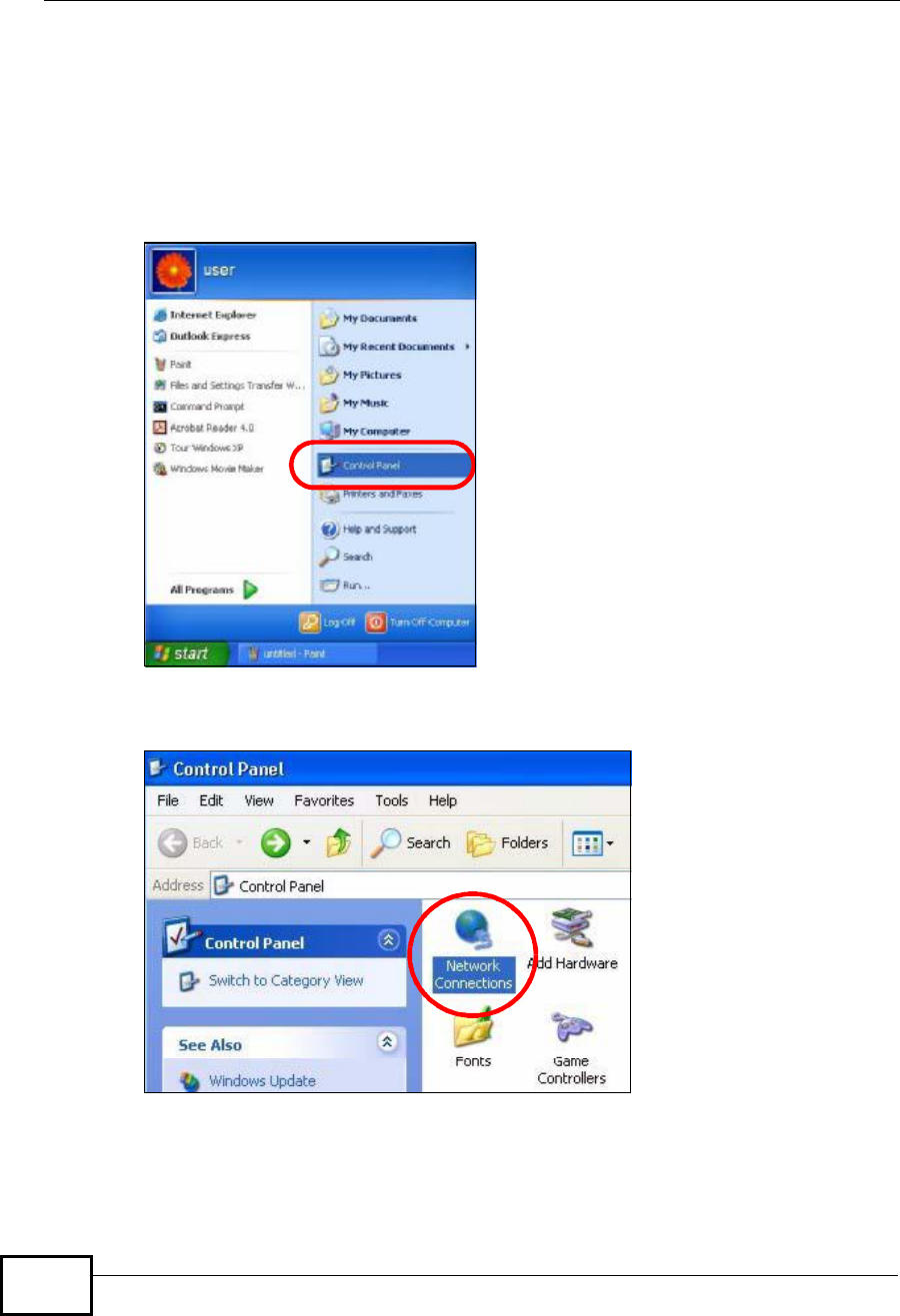
1Click Start >Control Panel.
Figure 128 Windows XP: Start Menu
2In the Control Panel, click the Network Connections icon.
Figure 129 Windows XP: Control Panel
Company Confidential
Appendix BSetting Up Your Computer’s IP Address
User’s Guide 285
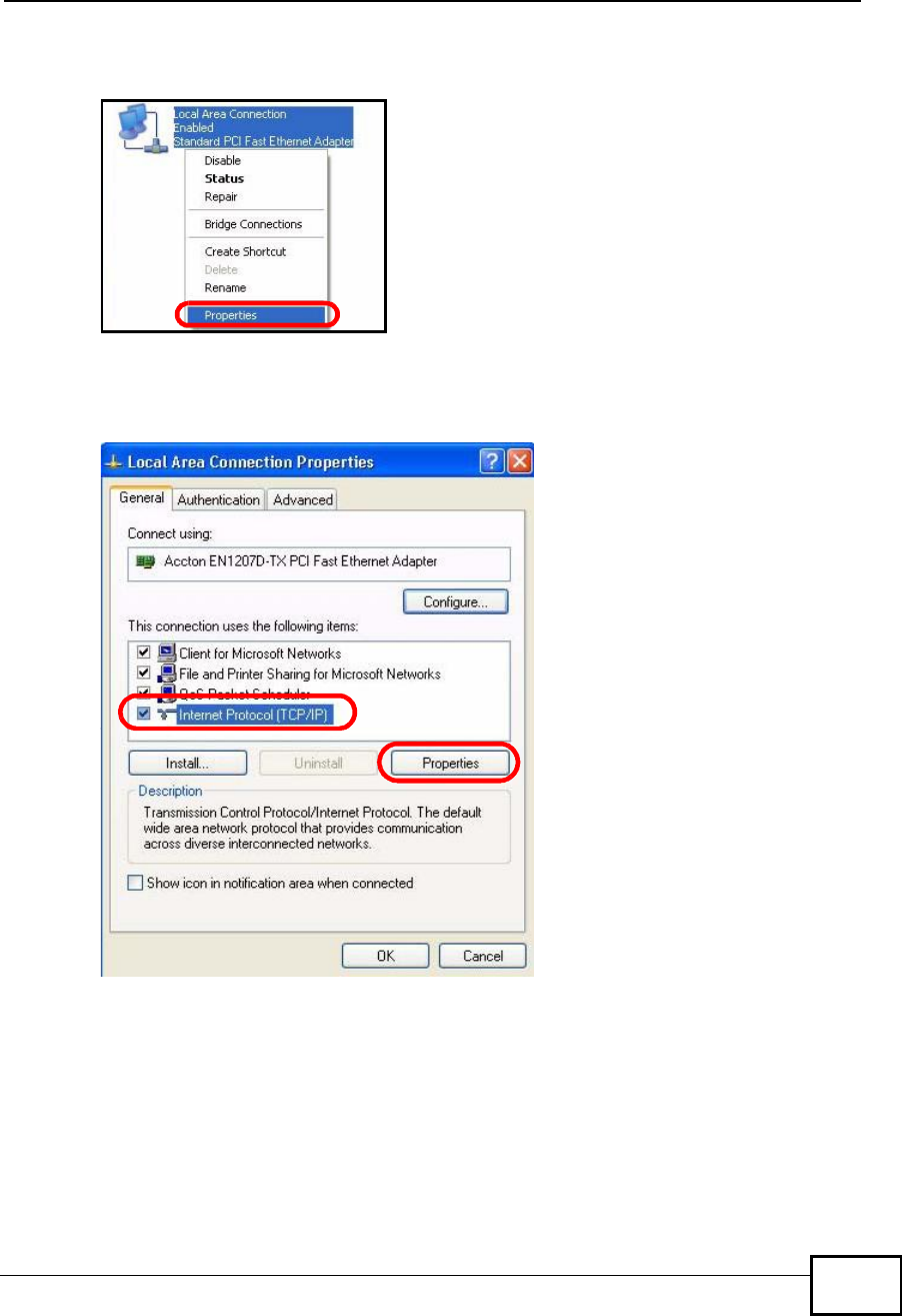
3Right-click Local Area Connection and then select Properties.
Figure 130 Windows XP: Control Panel > Network Connections > Properties
4On the General tab, select Internet Protocol (TCP/IP) and then click
Properties.
Figure 131 Windows XP: Local Area Connection Properties
Company Confidential
Appendix BSetting Up Your Computer’s IP Address
User’s Guide
286
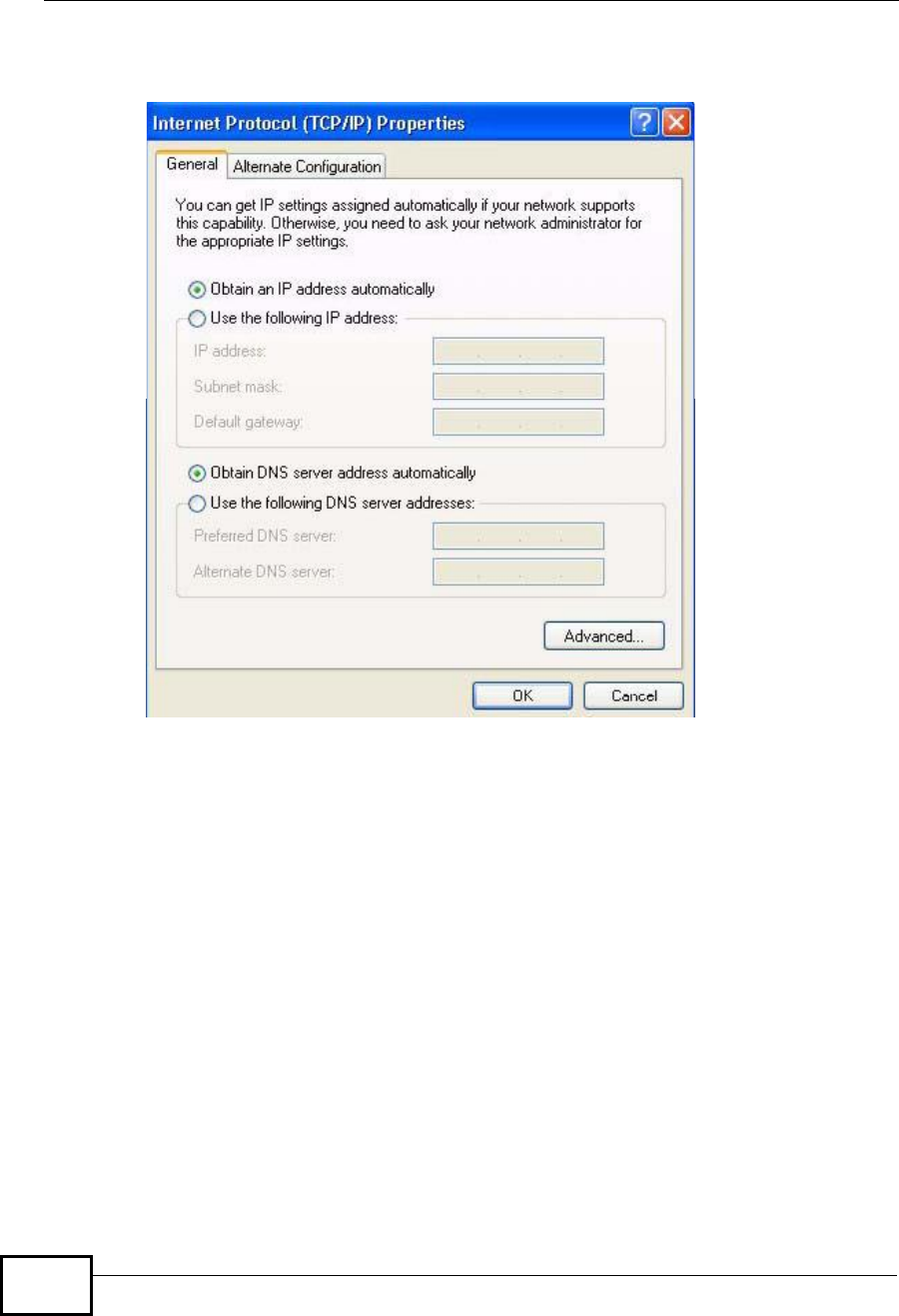
5The Internet Protocol TCP/IP Properties window opens.
Figure 132 Windows XP: Internet Protocol (TCP/IP) Properties
6Select Obtain an IP address automatically if your network administrator or ISP
assigns your IP address dynamically.
Select Use the following IP Address and fill in the IP address,Subnet mask,
and Default gateway fields if you have a static IP address that was assigned to
you by your network administrator or ISP. You may also have to enter a
Preferred DNS server and an AlternateDNS server, if that information was
provided.
7Click OK to close the Internet Protocol (TCP/IP) Properties window.
Click OK to close the Local Area Connection Properties window.Verifying Settings
1Click Start > All Programs > Accessories > Command Prompt.
2In the Command Prompt window, type "ipconfig" and then press [ENTER].
You can also go to Start > Control Panel > Network Connections, right-click a
network connection, click Status and then click the Support tab to view your IP
address and connection information.
Company Confidential
Appendix BSetting Up Your Computer’s IP Address
User’s Guide 287
Windows Vista
This section shows screens from Windows Vista Professional.
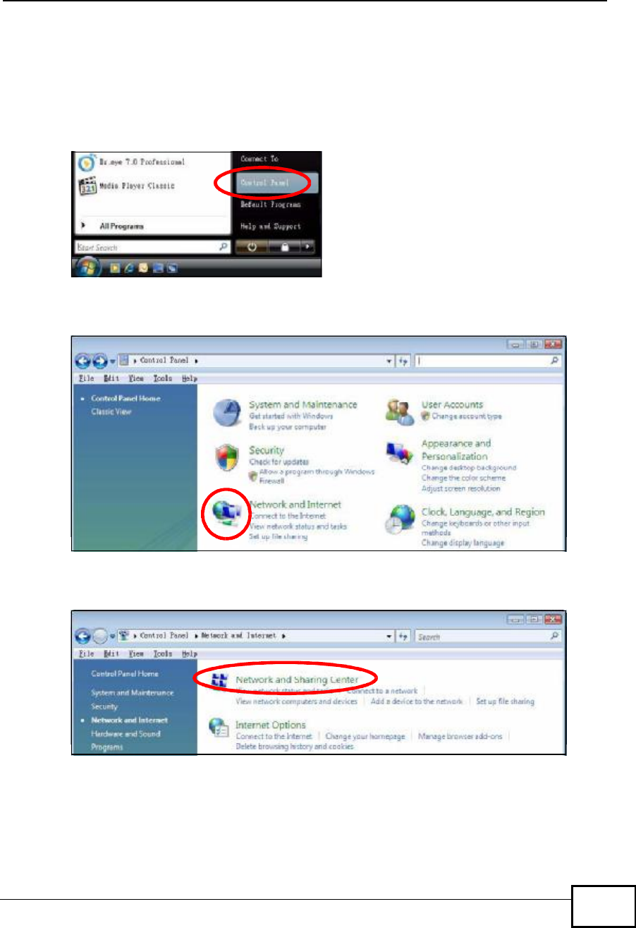
1Click Start > Control Panel.
Figure 133 Windows Vista: Start Menu
2In the Control Panel, click the Network and Internet icon.
Figure 134 Windows Vista: Control Panel
3Click the Network and Sharing Center icon.
Figure 135 Windows Vista: Network And Internet
Company Confidential
Appendix BSetting Up Your Computer’s IP Address
User’s Guide
288
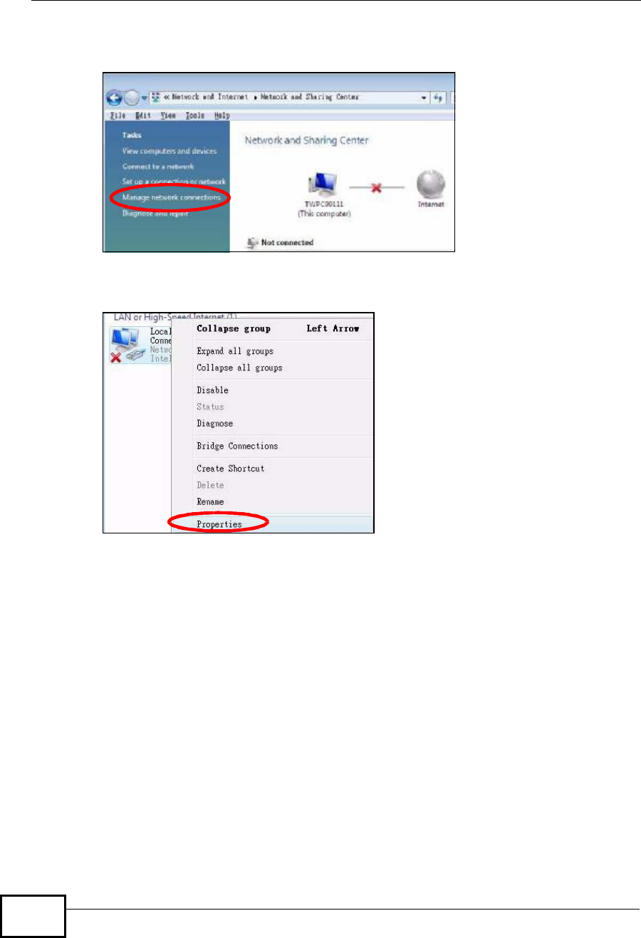
4Click Manage network connections.
Figure 136 Windows Vista: Network and Sharing Center
5Right-click Local Area Connection and then select Properties.
Figure 137 Windows Vista: Network and Sharing Center
Note: During this procedure, click Continue whenever Windows displays a screen
saying that it needs your permission to continue.
Company Confidential
Appendix BSetting Up Your Computer’s IP Address
User’s Guide 289
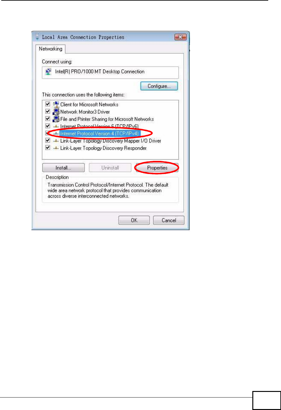
6Select Internet Protocol Version 4 (TCP/IPv4) and then select Properties.
Figure 138 Windows Vista: Local Area Connection Properties
Company Confidential
Appendix BSetting Up Your Computer’s IP Address
User’s Guide
290
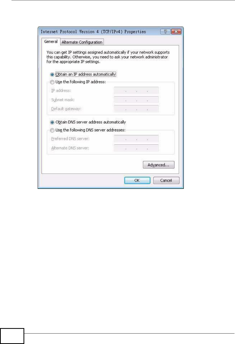
7The Internet Protocol Version 4 (TCP/IPv4) Properties window opens.
Figure 139 Windows Vista: Internet Protocol Version 4 (TCP/IPv4) Properties
8Select Obtain an IP address automatically if your network administrator or ISP
assigns your IP address dynamically.
Select Use the following IP Address and fill in the IP address,Subnet mask,
and Default gateway fields if you have a static IP address that was assigned to
you by your network administrator or ISP. You may also have to enter a
Preferred DNS server and an AlternateDNS server, if that information was
provided.Click Advanced.
9Click OK to close the Internet Protocol (TCP/IP) Properties window.
Click OK to close the Local Area Connection Properties window.Verifying Settings
1Click Start > All Programs > Accessories > Command Prompt.
2In the Command Prompt window, type "ipconfig" and then press [ENTER].
You can also go to Start > Control Panel > Network Connections, right-click a
network connection, click Status and then click the Support tab to view your IP
address and connection information.
Company Confidential
Appendix BSetting Up Your Computer’s IP Address
User’s Guide 291
Mac OS X: 10.3 and 10.4
The screens in this section are from Mac OS X 10.4 but can also apply to 10.3.
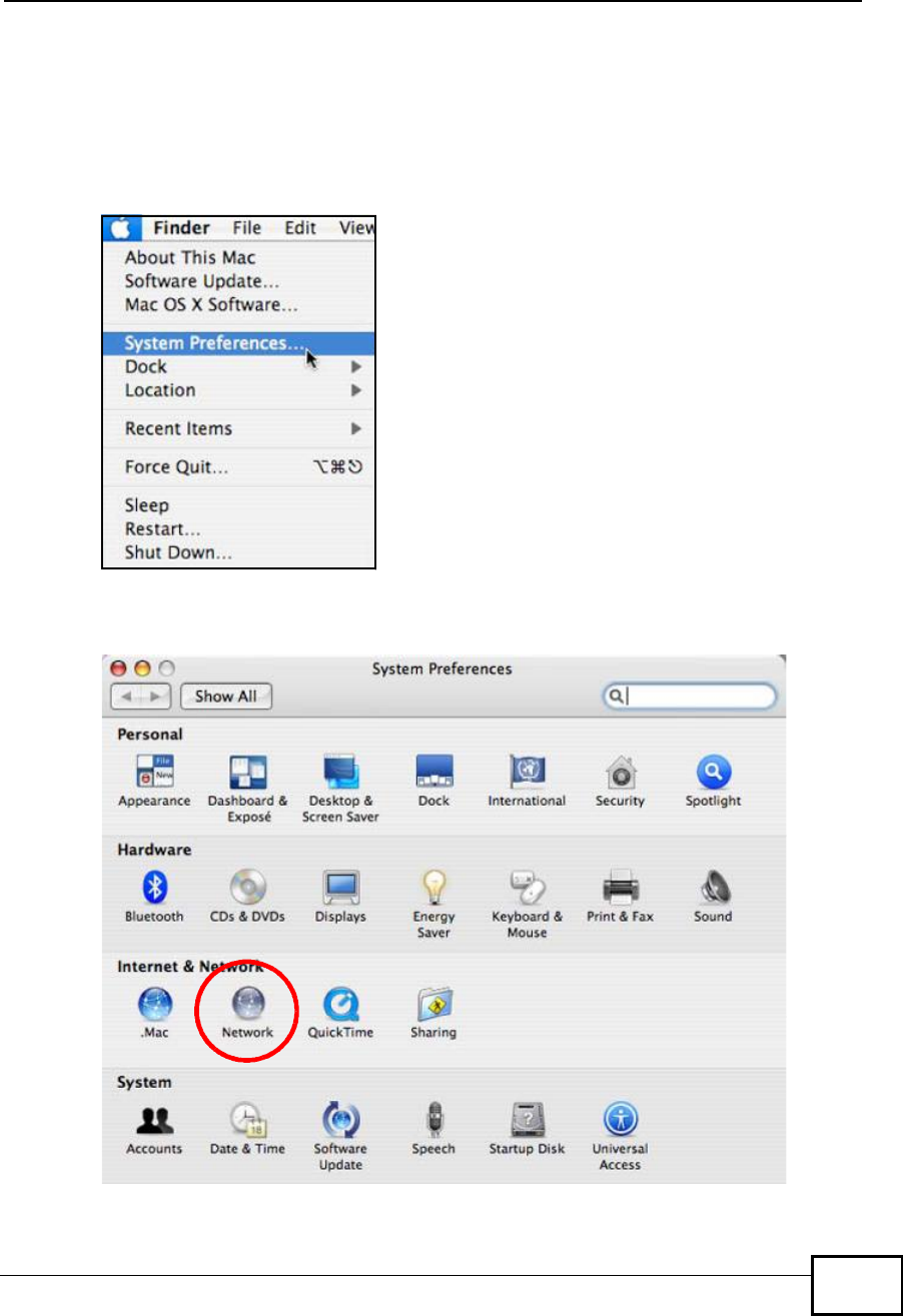
1Click Apple > System Preferences.
Figure 140 Mac OS X 10.4: Apple Menu
2In the System Preferences window, click the Network icon.
Figure 141 Mac OS X 10.4: System Preferences
Company Confidential
Appendix BSetting Up Your Computer’s IP Address
User’s Guide
292
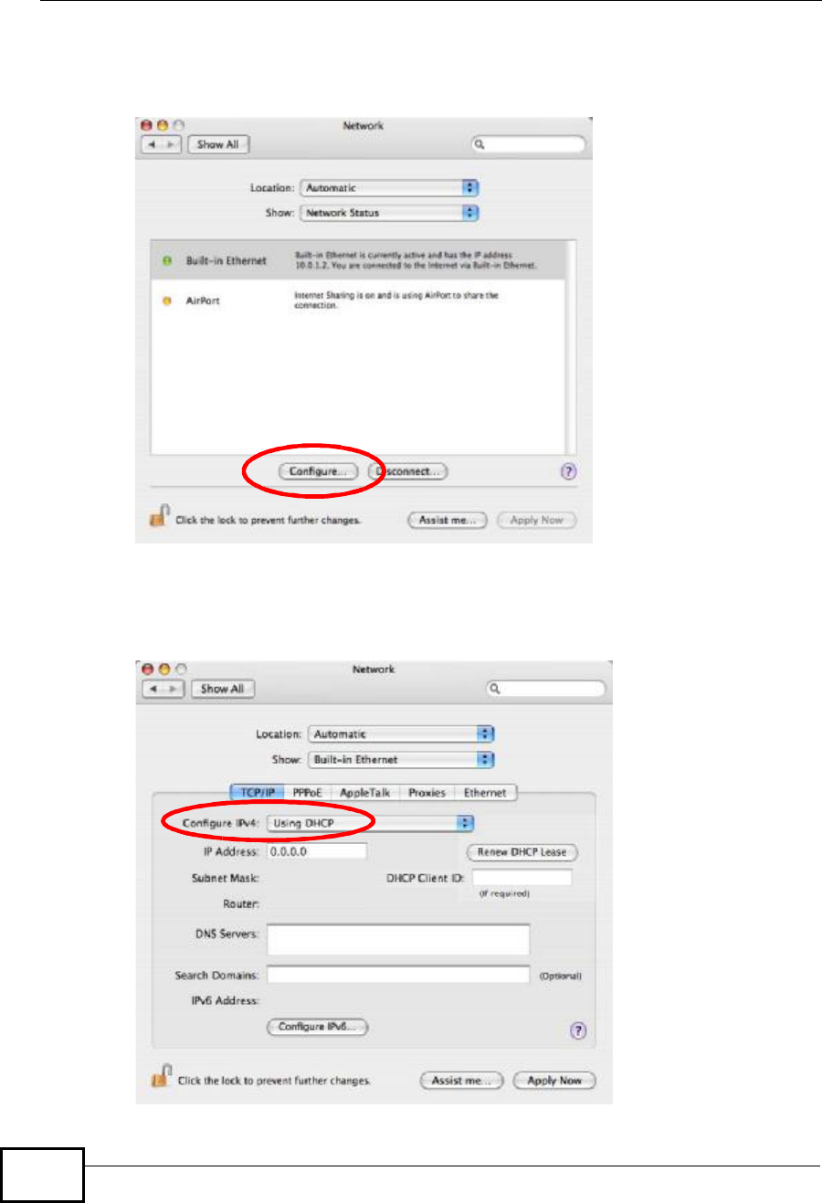
3When the Network preferences pane opens, select Built-in Ethernet from the
network connection type list, and then click Configure.
Figure 142 Mac OS X 10.4: Network Preferences
4For dynamically assigned settings, select Using DHCP from the Configure IPv4
list in the TCP/IP tab.
Figure 143 Mac OS X 10.4: Network Preferences > TCP/IP Tab.
Company Confidential
Appendix BSetting Up Your Computer’s IP Address
User’s Guide 293
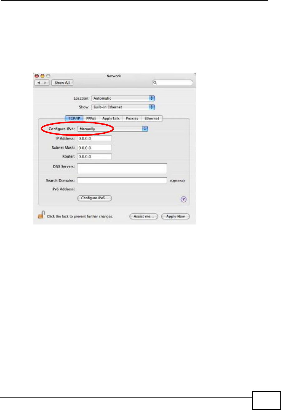
5For statically assigned settings, do the following:
•From the Configure IPv4 list, select Manually.
•In the IP Address field, type your IP address.
•In the Subnet Mask field, type your subnet mask.
•In the Router field, type the IP address of your device.
Figure 144 Mac OS X 10.4: Network Preferences > Ethernet
Company Confidential
Appendix BSetting Up Your Computer’s IP Address
User’s Guide
294
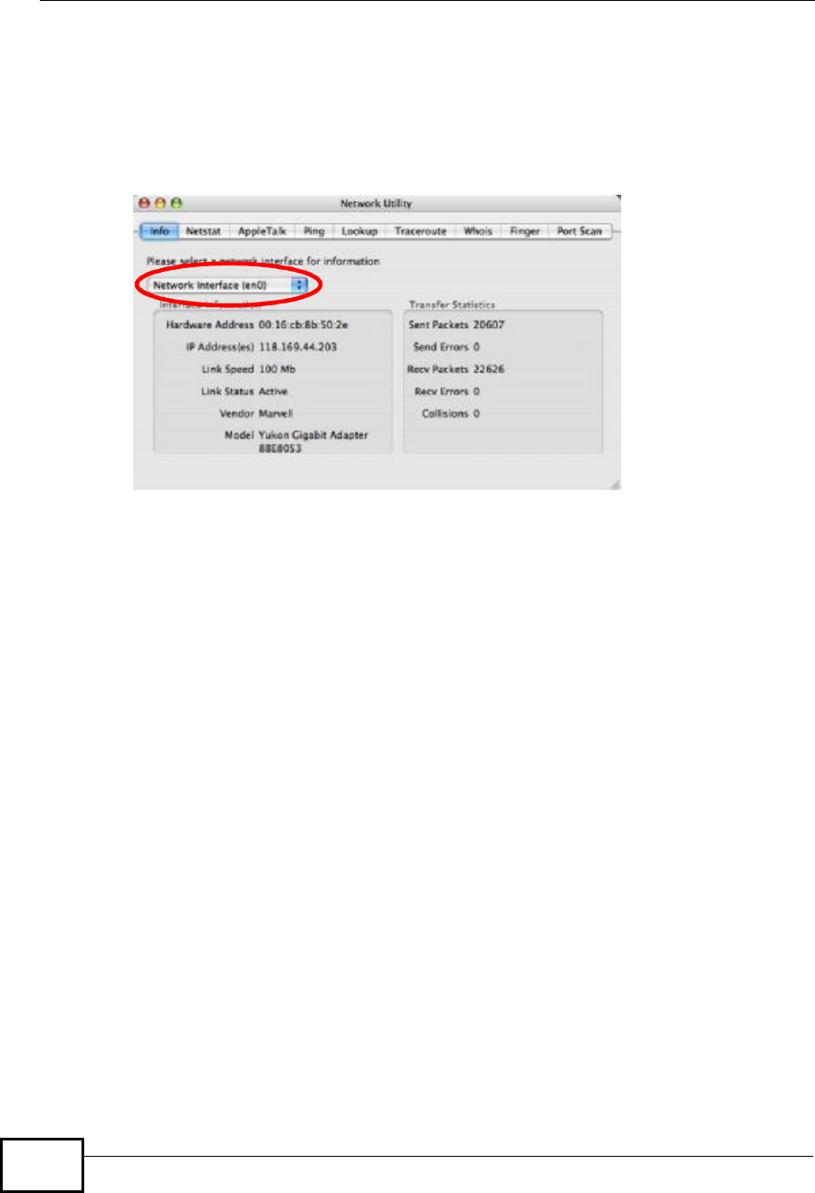
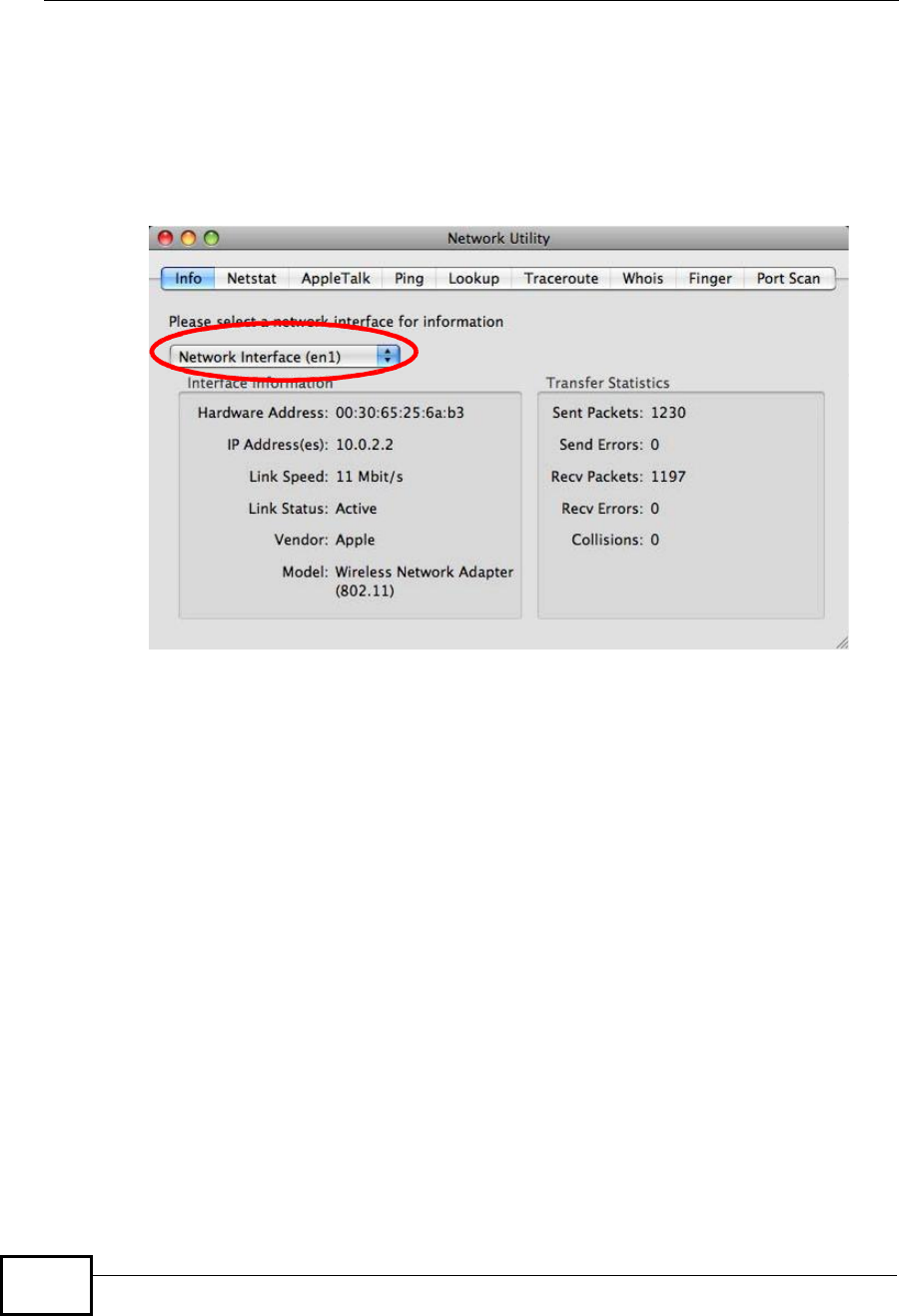
Click Apply Now and close the window.Verifying Settings
Check your TCP/IP properties by clicking Applications > Utilities > Network
Utilities, and then selecting the appropriate Network Interface from the Info
tab.
Figure 145 Mac OS X 10.4: Network Utility
Company Confidential
Appendix BSetting Up Your Computer’s IP Address
User’s Guide 295
Mac OS X: 10.5
The screens in this section are from Mac OS X 10.5.
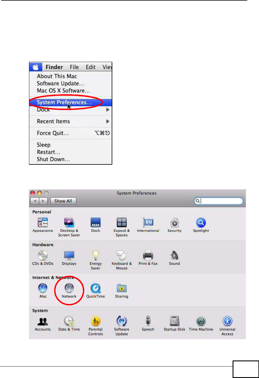
1Click Apple > System Preferences.
Figure 146 Mac OS X 10.5: Apple Menu
2In System Preferences, click the Network icon.
Figure 147 Mac OS X 10.5: Systems Preferences
Company Confidential
Appendix BSetting Up Your Computer’s IP Address
User’s Guide
296
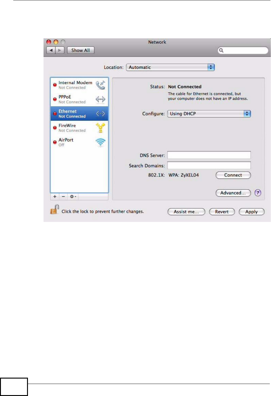
3When the Network preferences pane opens, select Ethernet from the list of
available connection types.
Figure 148 Mac OS X 10.5: Network Preferences > Ethernet
4From the Configure list, select Using DHCP for dynamically assigned settings.
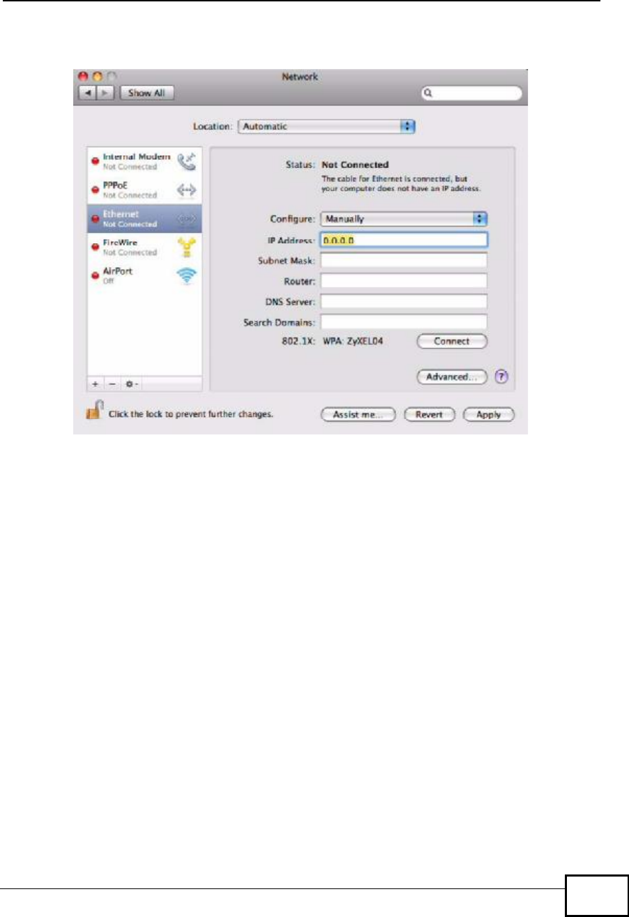
5For statically assigned settings, do the following:
•From the Configure list, select Manually.
•In the IP Address field, enter your IP address.
•In the Subnet Mask field, enter your subnet mask.
Company Confidential
Appendix BSetting Up Your Computer’s IP Address
User’s Guide 297
•In the Router field, enter the IP address of your WiMAX Device.
Figure 149 Mac OS X 10.5: Network Preferences > Ethernet
6Click Apply and close the window.
Company Confidential
Appendix BSetting Up Your Computer’s IP Address
User’s Guide
298
Verifying Settings
Check your TCP/IP properties by clicking Applications > Utilities > Network
Utilities, and then selecting the appropriate Network interface from the Info
tab.
Figure 150 Mac OS X 10.5: Network Utility
Linux: Ubuntu 8 (GNOME)
This section shows you how to configure your computer’s TCP/IP settings in the
GNU Object Model Environment (GNOME) using the Ubuntu 8 Linux distribution.
The procedure, screens and file locations may vary depending on your specific
distribution, release version, and individual configuration. The following screens
use the default Ubuntu 8 installation.
Note: Make sure you are logged in as the root administrator.
Follow the steps below to configure your computer IP address in GNOME:
Company Confidential
Appendix BSetting Up Your Computer’s IP Address
User’s Guide 299
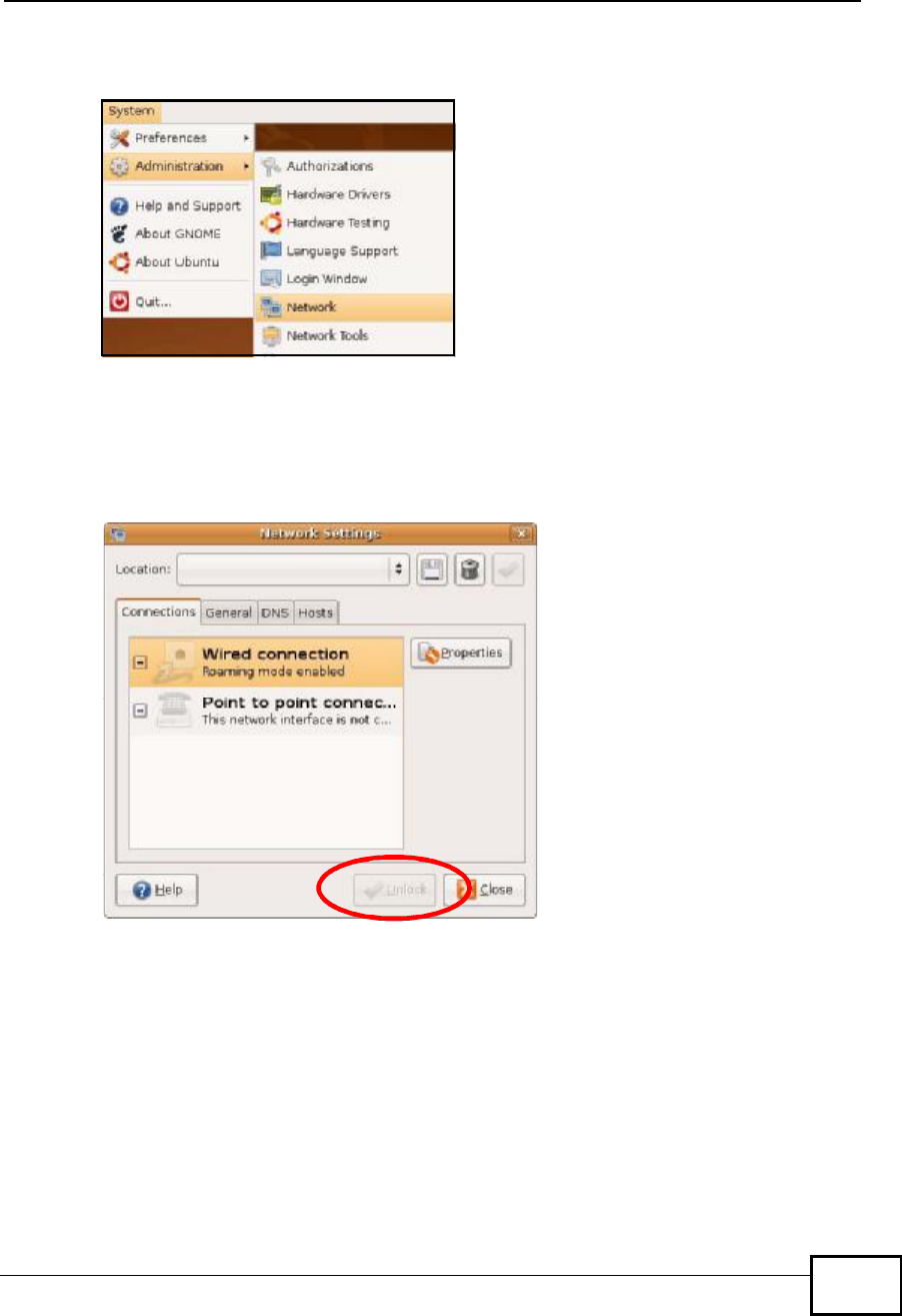
1Click System > Administration > Network.
Figure 151 Ubuntu 8: System > Administration Menu
2When the Network Settings window opens, click Unlock to open the
Authenticate window. (By default, the Unlock button is greyed out until clicked.)
You cannot make changes to your configuration unless you first enter your admin
password.
Figure 152 Ubuntu 8: Network Settings > Connections
Company Confidential
Appendix BSetting Up Your Computer’s IP Address
User’s Guide
300
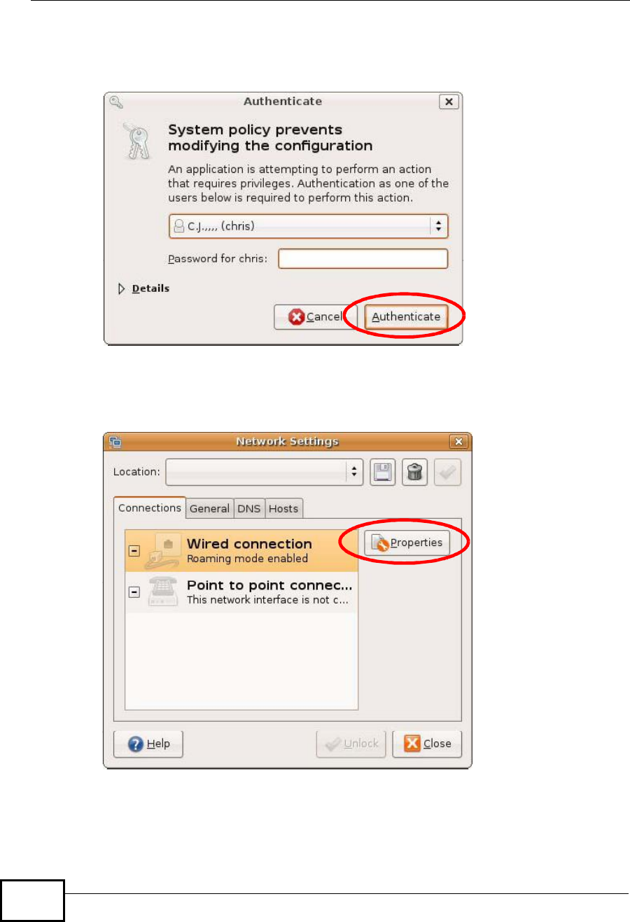
3In the Authenticate window, enter your admin account name and password then
click the Authenticate button.
Figure 153 Ubuntu 8: Administrator Account Authentication
4In the Network Settings window, select the connection that you want to
configure, then click Properties.
Figure 154 Ubuntu 8: Network Settings > Connections
Company Confidential
Appendix BSetting Up Your Computer’s IP Address
User’s Guide 301
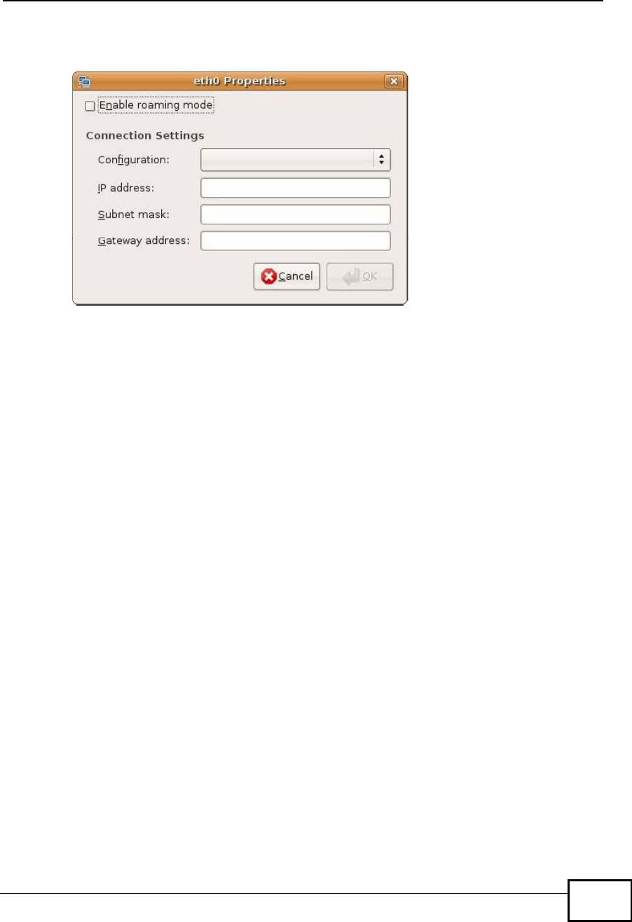
5The Properties dialog box opens.
Figure 155 Ubuntu 8: Network Settings > Properties
•In the Configuration list, select Automatic Configuration (DHCP) if you
have a dynamic IP address.
•In the Configuration list, select Static IP address if you have a static IP
address. Fill in the IP address,Subnet mask, and Gateway address fields.
6Click OK to save the changes and close the Properties dialog box and return to
the Network Settings screen.
Company Confidential
Appendix BSetting Up Your Computer’s IP Address
User’s Guide
302
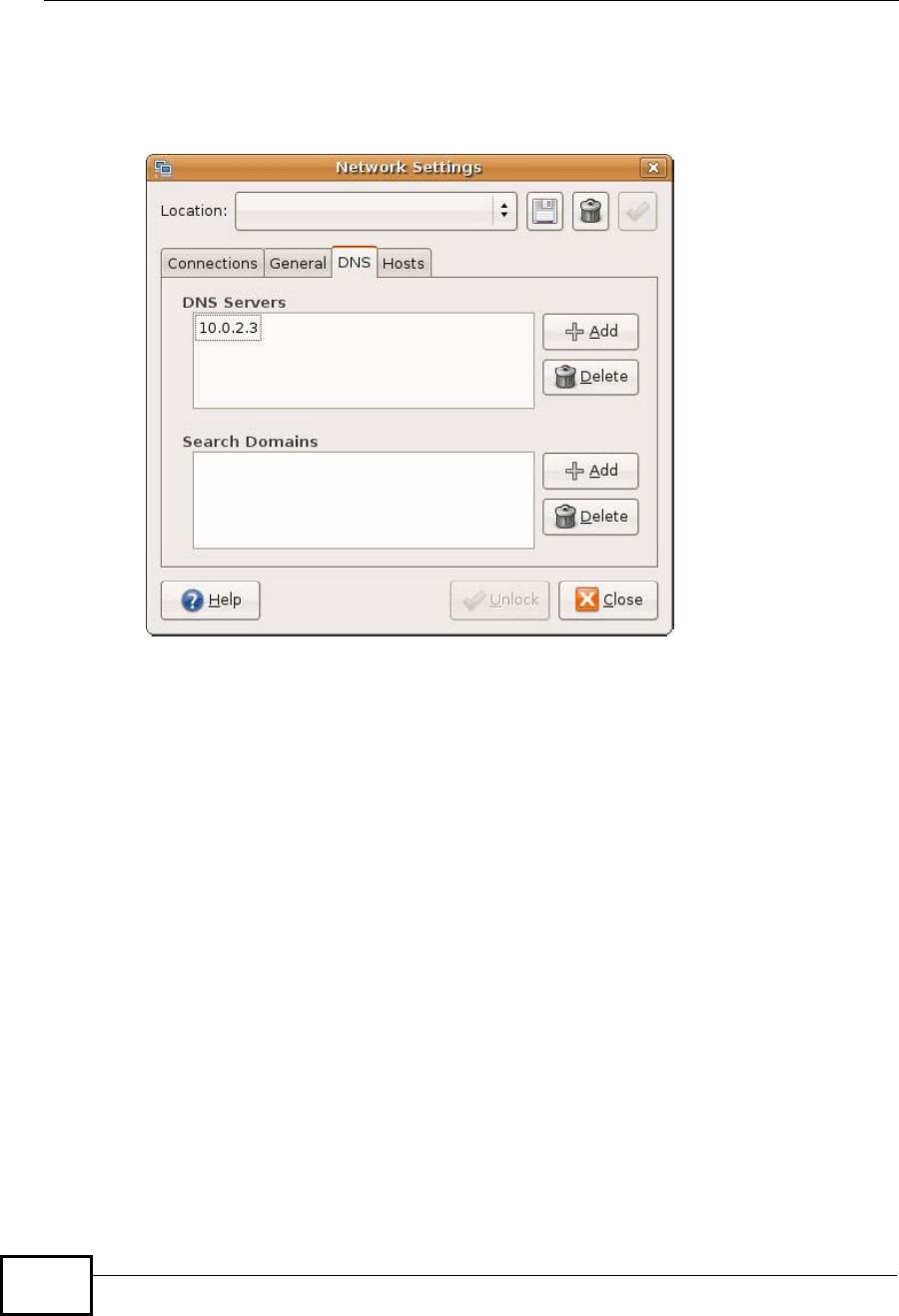
7If you know your DNS server IP address(es), click the DNS tab in the Network
Settings window and then enter the DNS server information in the fields
provided.
Figure 156 Ubuntu 8: Network Settings > DNS
8Click the Close button to apply the changes.
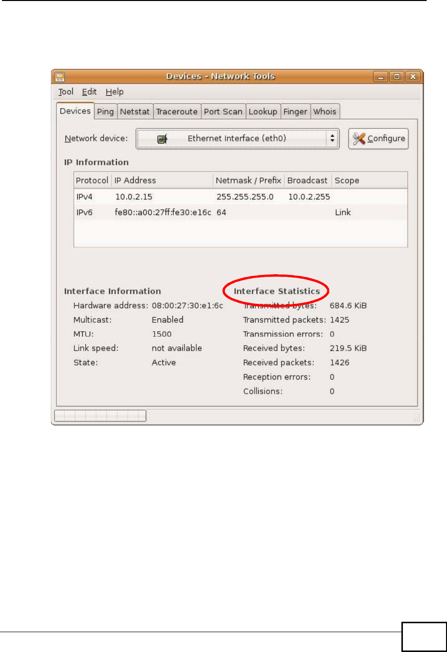
Verifying Settings
Check your TCP/IP properties by clicking System > Administration > Network
Tools, and then selecting the appropriate Network device from the Devices
Company Confidential
Appendix BSetting Up Your Computer’s IP Address
User’s Guide 303
tab. The Interface Statistics column shows data if your connection is working
properly.
Figure 157 Ubuntu 8: Network Tools
Company Confidential
Appendix BSetting Up Your Computer’s IP Address
User’s Guide
304
Linux: openSUSE 10.3 (KDE)
This section shows you how to configure your computer’s TCP/IP settings in the K
Desktop Environment (KDE) using the openSUSE 10.3 Linux distribution. The
procedure, screens and file locations may vary depending on your specific
distribution, release version, and individual configuration. The following screens
use the default openSUSE 10.3 installation.
Note: Make sure you are logged in as the root administrator.
Follow the steps below to configure your computer IP address in the KDE:
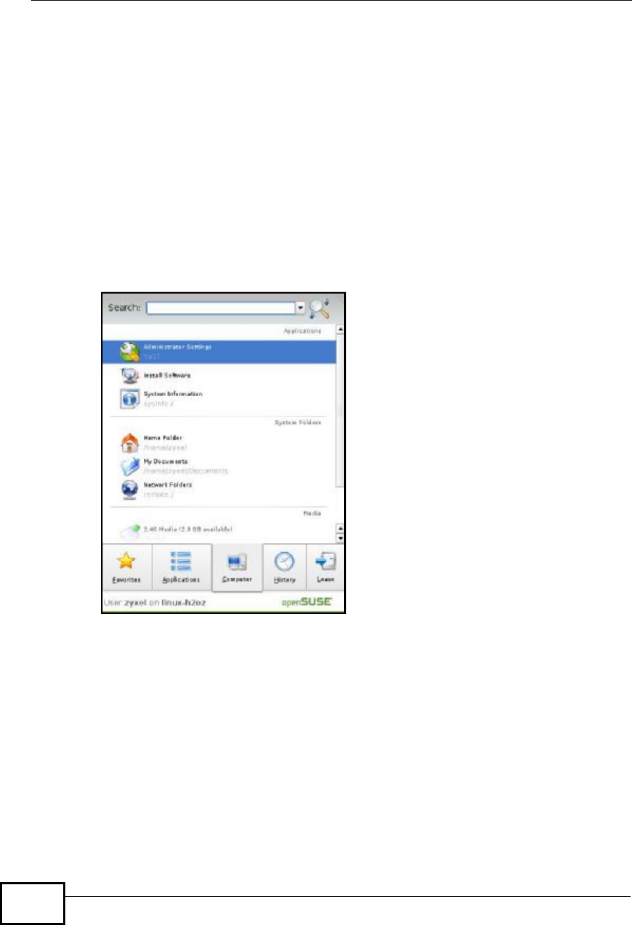
1Click K Menu > Computer > Administrator Settings (YaST).
Figure 158 openSUSE 10.3: K Menu > Computer Menu
Company Confidential
Appendix BSetting Up Your Computer’s IP Address
User’s Guide 305
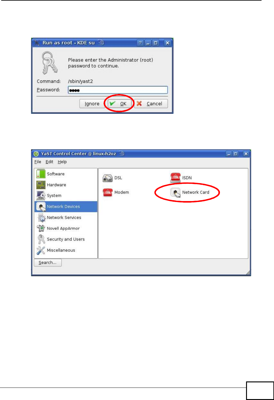
2When the Run as Root - KDE su dialog opens, enter the admin password and
click OK.
Figure 159 openSUSE 10.3: K Menu > Computer Menu
3When the YaST Control Center window opens, select Network Devices and
then click the Network Card icon.
Figure 160 openSUSE 10.3: YaST Control Center
Company Confidential
Appendix BSetting Up Your Computer’s IP Address
User’s Guide
306
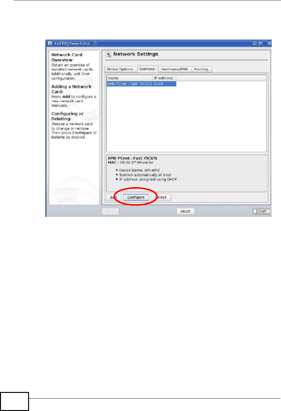
4When the Network Settings window opens, click the Overview tab, select the
appropriate connection Name from the list, and then click the Configure button.
Figure 161 openSUSE 10.3: Network Settings
Company Confidential
Appendix BSetting Up Your Computer’s IP Address
User’s Guide 307
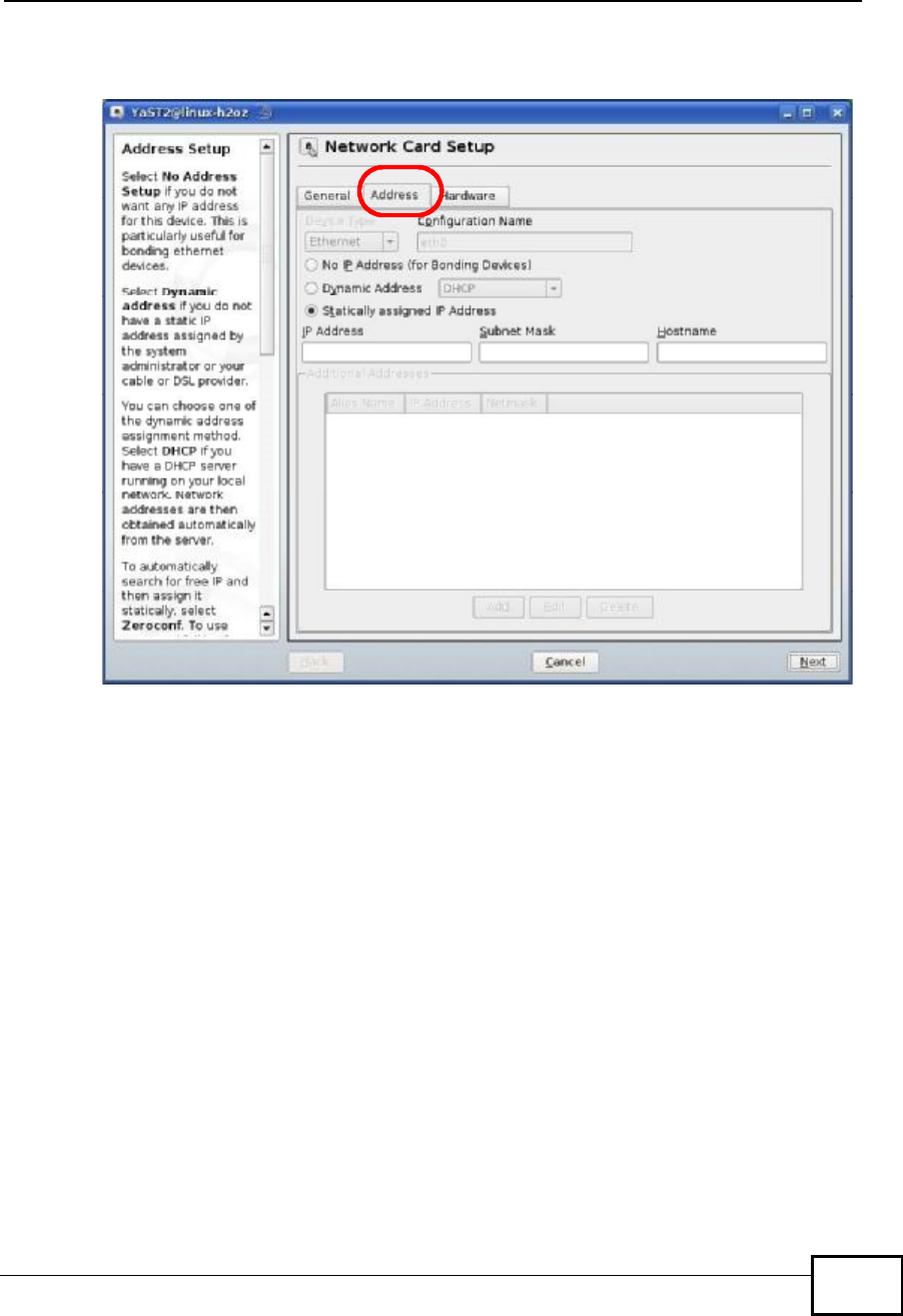
5When the Network Card Setup window opens, click the Address tab
Figure 162 openSUSE 10.3: Network Card Setup
6Select Dynamic Address (DHCP) if you have a dynamic IP address.
Select Statically assigned IP Address if you have a static IP address. Fill in the
IP address,Subnet mask, and Hostname fields.
7Click Next to save the changes and close the Network Card Setup window.
Company Confidential
Appendix BSetting Up Your Computer’s IP Address
User’s Guide
308
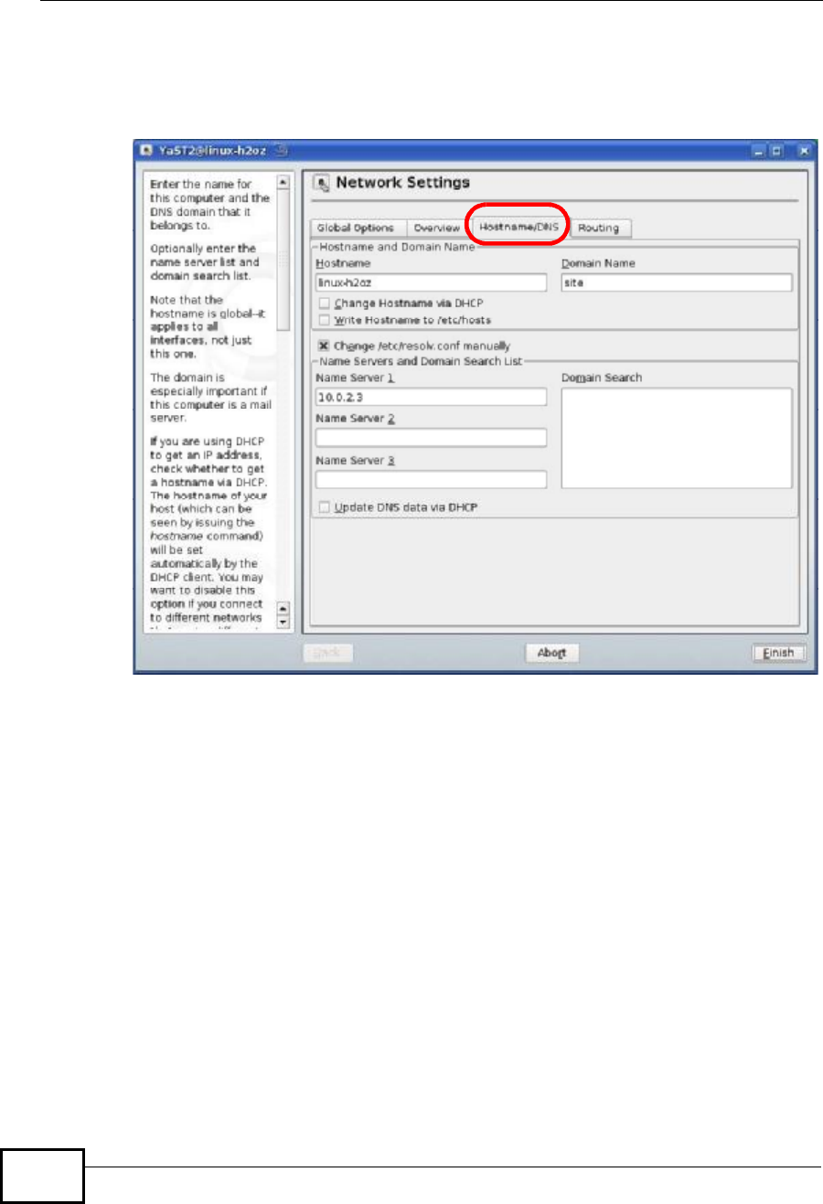
8If you know your DNS server IP address(es), click the Hostname/DNS tab in
Network Settings and then enter the DNS server information in the fields
provided.
Figure 163 openSUSE 10.3: Network Settings
9Click Finish to save your settings and close the window.
Company Confidential
Appendix BSetting Up Your Computer’s IP Address
User’s Guide 309
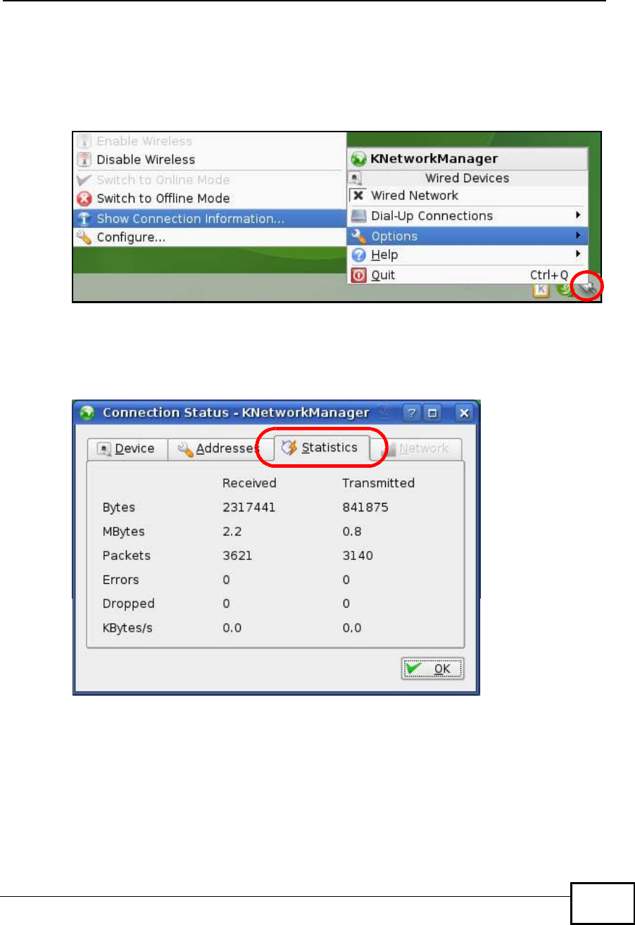
Verifying Settings
Click the KNetwork Manager icon on the Task bar to check your TCP/IP
properties. From the Options sub-menu, select Show Connection Information.
Figure 164 openSUSE 10.3: KNetwork Manager
When the Connection Status - KNetwork Manager window opens, click the
Statistics tab to see if your connection is working properly.
Figure 165 openSUSE: Connection Status - KNetwork Manager
Company Confidential

Appendix BSetting Up Your Computer’s IP Address
User’s Guide
310
Company Confidential
User’s Guide 311
APPENDIX C
Wireless LANs
Wireless LAN Topologies
This section discusses ad-hoc and infrastructure wireless LAN topologies.
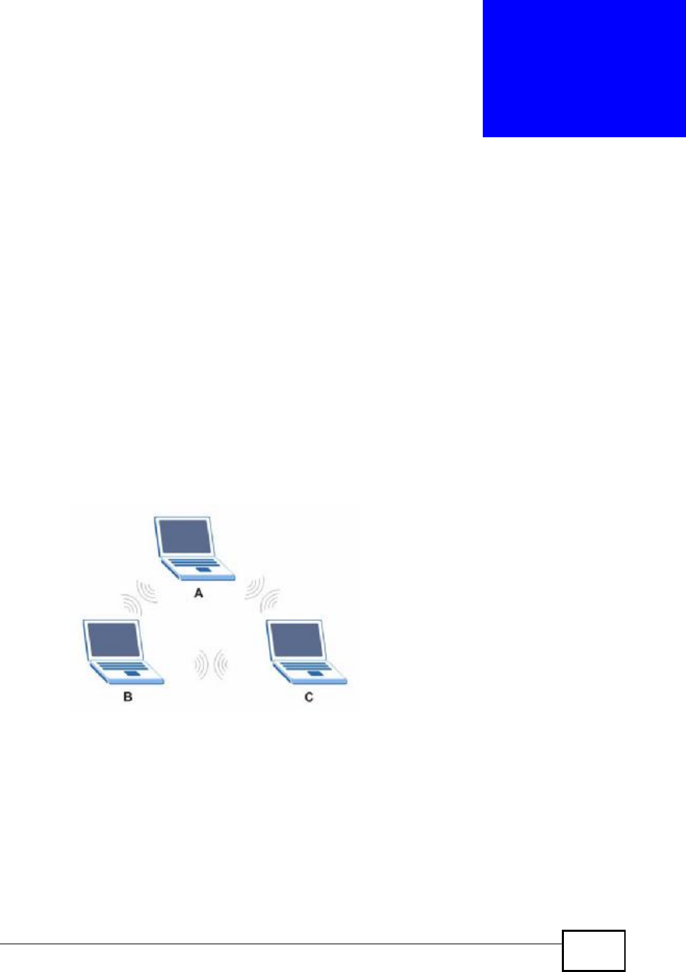
Ad-hoc Wireless LAN Configuration
The simplest WLAN configuration is an independent (Ad-hoc) WLAN that connects
a set of computers with wireless adapters (A, B, C). Any time two or more wireless
adapters are within range of each other, they can set up an independent network,
which is commonly referred to as an ad-hoc network or Independent Basic Service
Set (IBSS). The following diagram shows an example of notebook computers
using wireless adapters to form an ad-hoc wireless LAN.
Figure 166 Peer-to-Peer Communication in an Ad-hoc Network
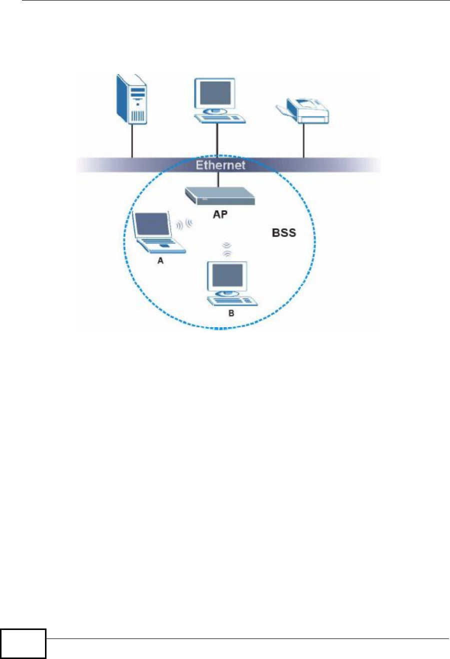
BSS
A Basic Service Set (BSS) exists when all communications between wireless
clients or between a wireless client and a wired network client go through one
access point (AP).
Intra-BSS traffic is traffic between wireless clients in the BSS. When Intra-BSS is
enabled, wireless client A and B can access the wired network and communicate
Company Confidential
Appendix CWireless LANs
User’s Guide
312
with each other. When Intra-BSS is disabled, wireless client A and B can still
access the wired network but cannot communicate with each other.
Figure 167 Basic Service Set
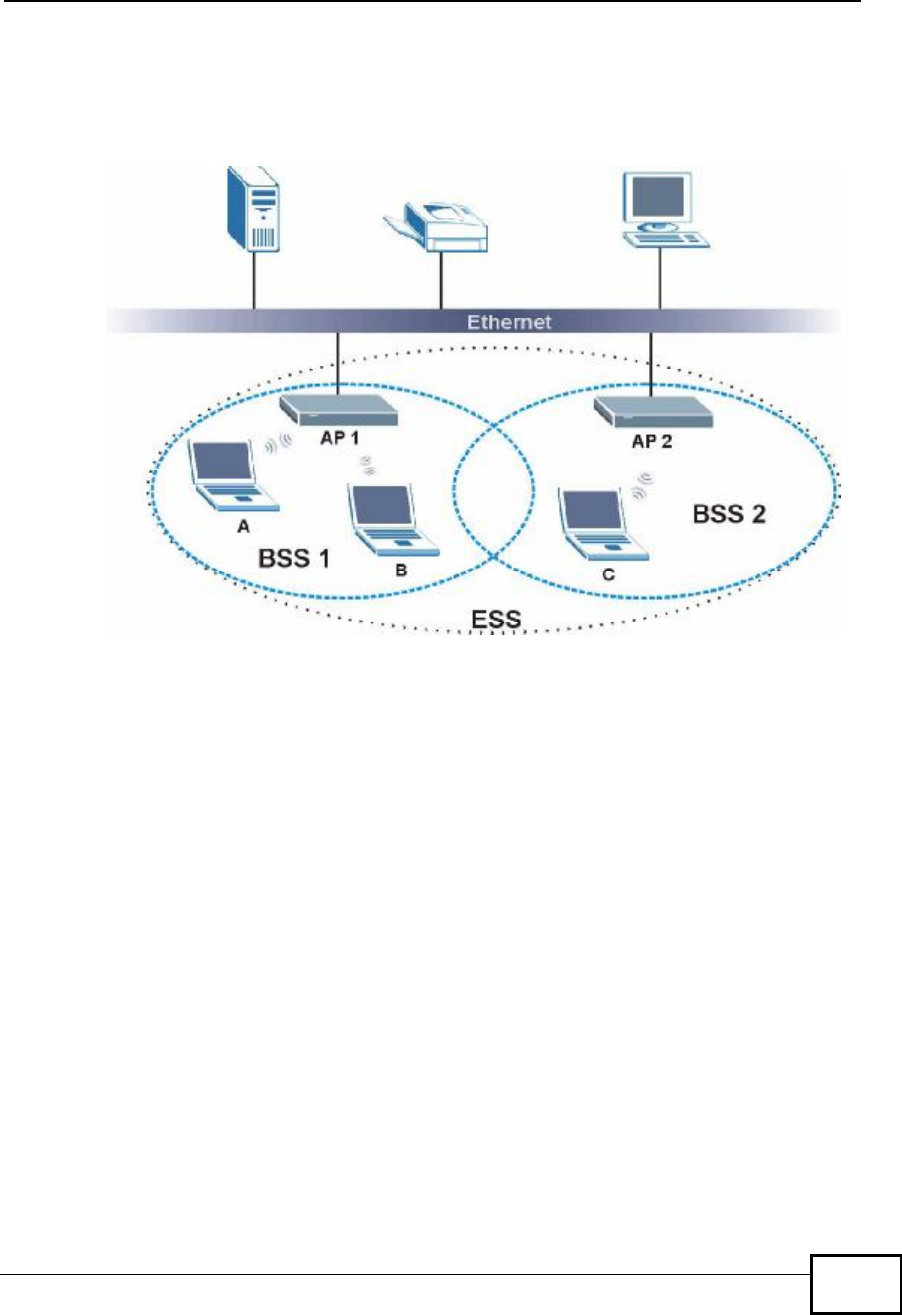
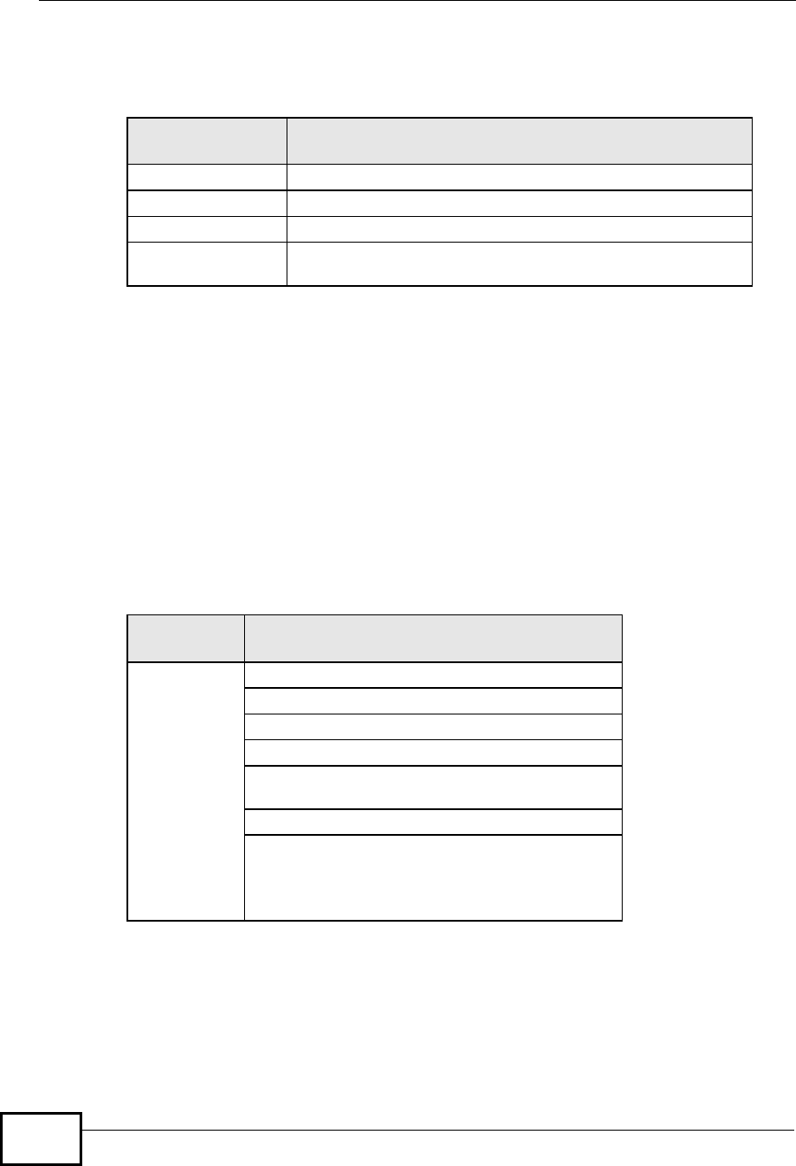
ESS
An Extended Service Set (ESS) consists of a series of overlapping BSSs, each
containing an access point, with each access point connected together by a wired
network. This wired connection between APs is called a Distribution System (DS).
This type of wireless LAN topology is called an Infrastructure WLAN. The Access
Points not only provide communication with the wired network but also mediate
wireless network traffic in the immediate neighborhood.
Company Confidential
Appendix CWireless LANs
User’s Guide 313
An ESSID (ESS IDentification) uniquely identifies each ESS. All access points and
their associated wireless clients within the same ESS must have the same ESSID
in order to communicate.
Figure 168 Infrastructure WLAN
Channel
A channel is the radio frequency(ies) used by wireless devices to transmit and
receive data. Channels available depend on your geographical area. You may have
a choice of channels (for your region) so you should use a channel different from
an adjacent AP (access point) to reduce interference. Interference occurs when
radio signals from different access points overlap causing interference and
degrading performance.
Adjacent channels partially overlap however. To avoid interference due to overlap,
your AP should be on a channel at least five channels away from a channel that an
adjacent AP is using. For example, if your region has 11 channels and an adjacent
AP is using channel 1, then you need to select a channel between 6 or 11.
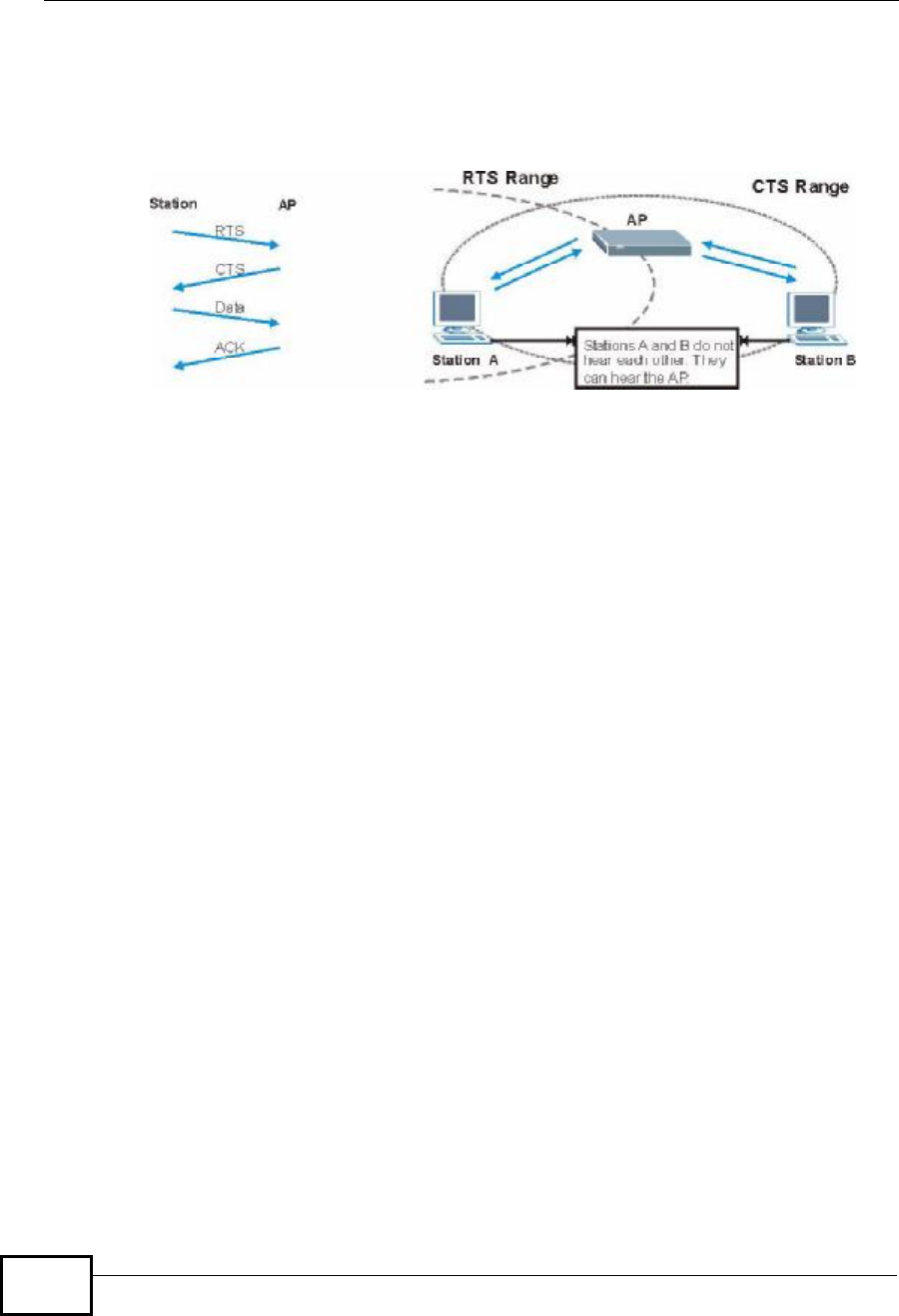
RTS/CTS
A hidden node occurs when two stations are within range of the same access
point, but are not within range of each other. The following figure illustrates a
hidden node. Both stations (STA) are within range of the access point (AP) or
Company Confidential
Appendix CWireless LANs
User’s Guide
314
wireless gateway, but out-of-range of each other, so they cannot "hear" each
other, that is they do not know if the channel is currently being used. Therefore,
they are considered hidden from each other.
Figure 169 RTS/CTS
When station A sends data to the AP, it might not know that the station B is
already using the channel. If these two stations send data at the same time,
collisions may occur when both sets of data arrive at the AP at the same time,
resulting in a loss of messages for both stations.
RTS/CTS is designed to prevent collisions due to hidden nodes. An RTS/CTS
defines the biggest size data frame you can send before an RTS (Request To
Send)/CTS (Clear to Send) handshake is invoked.
When a data frame exceeds the RTS/CTS value you set (between 0 to 2432
bytes), the station that wants to transmit this frame must first send an RTS
(Request To Send) message to the AP for permission to send it. The AP then
responds with a CTS (Clear to Send) message to all other stations within its range
to notify them to defer their transmission. It also reserves and confirms with the
requesting station the time frame for the requested transmission.
Stations can send frames smaller than the specified RTS/CTS directly to the AP
without the RTS (Request To Send)/CTS (Clear to Send) handshake.
You should only configure RTS/CTS if the possibility of hidden nodes exists on
your network and the "cost" of resending large frames is more than the extra
network overhead involved in the RTS (Request To Send)/CTS (Clear to Send)
handshake.
If the RTS/CTS value is greater than the Fragmentation Threshold value (see
next), then the RTS (Request To Send)/CTS (Clear to Send) handshake will never
occur as data frames will be fragmented before they reach RTS/CTS size.
Note: Enabling the RTS Threshold causes redundant network overhead that could
negatively affect the throughput performance instead of providing a remedy.
Company Confidential

Appendix CWireless LANs
User’s Guide 315
Fragmentation Threshold
AFragmentation Threshold is the maximum data fragment size (between 256
and 2432 bytes) that can be sent in the wireless network before the AP will
fragment the packet into smaller data frames.
A large Fragmentation Threshold is recommended for networks not prone to
interference while you should set a smaller threshold for busy networks or
networks that are prone to interference.
If the Fragmentation Threshold value is smaller than the RTS/CTS value (see
previously) you set then the RTS (Request To Send)/CTS (Clear to Send)
handshake will never occur as data frames will be fragmented before they reach
RTS/CTS size.
Preamble Type
Preamble is used to signal that data is coming to the receiver. Short and long refer
to the length of the synchronization field in a packet.
Short preamble increases performance as less time sending preamble means
more time for sending data. All IEEE 802.11 compliant wireless adapters support
long preamble, but not all support short preamble.
Use long preamble if you are unsure what preamble mode other wireless devices
on the network support, and to provide more reliable communications in busy
wireless networks.
Use short preamble if you are sure all wireless devices on the network support it,
and to provide more efficient communications.
Use the dynamic setting to automatically use short preamble when all wireless
devices on the network support it, otherwise the WiMAX Device uses long
preamble.
Note: The wireless devices MUSTuse the same preamble mode in order to
communicate.
IEEE 802.11g Wireless LAN
IEEE 802.11g is fully compatible with the IEEE 802.11b standard. This means an
IEEE 802.11b adapter can interface directly with an IEEE 802.11g access point
(and vice versa) at 11 Mbps or lower depending on range. IEEE 802.11g has
Company Confidential
Appendix CWireless LANs
User’s Guide
316
several intermediate rate steps between the maximum and minimum data rates.
The IEEE 802.11g data rate and modulation are as follows:
Wireless Security Overview
Wireless security is vital to your network to protect wireless communication
between wireless clients, access points and the wired network.
Wireless security methods available on the WiMAX Device are data encryption,
wireless client authentication, restricting access by device MAC address and hiding
the WiMAX Device identity.
The following figure shows the relative effectiveness of these wireless security
methods available on your WiMAX Device.
Note: You must enable the same wireless security settings on the WiMAX Device and
on all wireless clients that you want to associate with it.
Table 123 IEEE 802.11g
DATA RATE
(MBPS) MODULATION
1DBPSK (Differential Binary Phase Shift Keyed)
2DQPSK (Differential Quadrature Phase Shift Keying)
5.5 / 11CCK (Complementary Code Keying)
6/9/12/18/24/36/
48/54 OFDM (Orthogonal Frequency Division Multiplexing)
Table 124 Wireless Security Levels
SECURITY
LEVEL SECURITY TYPE
Least
Secure
Most Secure
Unique SSID (Default)
Unique SSID with Hide SSID Enabled
MAC Address Filtering
WEP Encryption
IEEE802.1x EAP with RADIUS Server
Authentication
Wi-Fi Protected Access (WPA)
WPA2
Company Confidential

Appendix CWireless LANs
User’s Guide 317
IEEE 802.1x
In June 2001, the IEEE 802.1x standard was designed to extend the features of
IEEE 802.11 to support extended authentication as well as providing additional
accounting and control features. It is supported by Windows XP and a number of
network devices. Some advantages of IEEE 802.1x are:
•User based identification that allows for roaming.
•Support for RADIUS (Remote Authentication Dial In User Service, RFC 2138,
2139) for centralized user profile and accounting management on a network
RADIUS server.
•Support for EAP (Extensible Authentication Protocol, RFC 2486) that allows
additional authentication methods to be deployed with no changes to the access
point or the wireless clients.
RADIUS
RADIUS is based on a client-server model that supports authentication,
authorization and accounting. The access point is the client and the server is the
RADIUS server. The RADIUS server handles the following tasks:
•Authentication
Determines the identity of the users.
•Authorization
Determines the network services available to authenticated users once they are
connected to the network.
•Accounting
Keeps track of the client’s network activity.
RADIUS is a simple package exchange in which your AP acts as a message relay
between the wireless client and the network RADIUS server.
Types of RADIUS Messages
The following types of RADIUS messages are exchanged between the access point
and the RADIUS server for user authentication:
•Access-Request
Sent by an access point requesting authentication.
•Access-Reject
Sent by a RADIUS server rejecting access.
•Access-Accept
Sent by a RADIUS server allowing access.
Company Confidential

Appendix CWireless LANs
User’s Guide
318
•Access-Challenge
Sent by a RADIUS server requesting more information in order to allow access.
The access point sends a proper response from the user and then sends another
Access-Request message.
The following types of RADIUS messages are exchanged between the access point
and the RADIUS server for user accounting:
•Accounting-Request
Sent by the access point requesting accounting.
•Accounting-Response
Sent by the RADIUS server to indicate that it has started or stopped accounting.
In order to ensure network security, the access point and the RADIUS server use a
shared secret key, which is a password, they both know. The key is not sent over
the network. In addition to the shared key, password information exchanged is
also encrypted to protect the network from unauthorized access.
Types of EAP Authentication
This section discusses some popular authentication types: EAP-MD5, EAP-TLS,
EAP-TTLS, PEAP and LEAP. Your wireless LAN device may not support all
authentication types.
EAP (Extensible Authentication Protocol) is an authentication protocol that runs on
top of the IEEE 802.1x transport mechanism in order to support multiple types of
user authentication. By using EAP to interact with an EAP-compatible RADIUS
server, an access point helps a wireless station and a RADIUS server perform
authentication.
The type of authentication you use depends on the RADIUS server and an
intermediary AP(s) that supports IEEE 802.1x. .
For EAP-TLS authentication type, you must first have a wired connection to the
network and obtain the certificate(s) from a certificate authority (CA). A certificate
(also called digital IDs) can be used to authenticate users and a CA issues
certificates and guarantees the identity of each certificate owner.
EAP-MD5 (Message-Digest Algorithm 5)
MD5 authentication is the simplest one-way authentication method. The
authentication server sends a challenge to the wireless client. The wireless client
‘proves’ that it knows the password by encrypting the password with the challenge
and sends back the information. Password is not sent in plain text.
Company Confidential

Appendix CWireless LANs
User’s Guide 319
However, MD5 authentication has some weaknesses. Since the authentication
server needs to get the plaintext passwords, the passwords must be stored. Thus
someone other than the authentication server may access the password file. In
addition, it is possible to impersonate an authentication server as MD5
authentication method does not perform mutual authentication. Finally, MD5
authentication method does not support data encryption with dynamic session
key. You must configure WEP encryption keys for data encryption.
EAP-TLS (Transport Layer Security)
With EAP-TLS, digital certifications are needed by both the server and the wireless
clients for mutual authentication. The server presents a certificate to the client.
After validating the identity of the server, the client sends a different certificate to
the server. The exchange of certificates is done in the open before a secured
tunnel is created. This makes user identity vulnerable to passive attacks. A digital
certificate is an electronic ID card that authenticates the sender’s identity.
However, to implement EAP-TLS, you need a Certificate Authority (CA) to handle
certificates, which imposes a management overhead.
EAP-TTLS (Tunneled Transport Layer Service)
EAP-TTLS is an extension of the EAP-TLS authentication that uses certificates for
only the server-side authentications to establish a secure connection. Client
authentication is then done by sending username and password through the
secure connection, thus client identity is protected. For client authentication, EAP-
TTLS supports EAP methods and legacy authentication methods such as PAP,
CHAP, MS-CHAP and MS-CHAP v2.
PEAP (Protected EAP)
Like EAP-TTLS, server-side certificate authentication is used to establish a secure
connection, then use simple username and password methods through the
secured connection to authenticate the clients, thus hiding client identity.
However, PEAP only supports EAP methods, such as EAP-MD5, EAP-MSCHAPv2
and EAP-GTC (EAP-Generic Token Card), for client authentication. EAP-GTC is
implemented only by Cisco.
LEAP
LEAP (Lightweight Extensible Authentication Protocol) is a Cisco implementation of
IEEE 802.1x.
Company Confidential
Appendix CWireless LANs
User’s Guide
320
Dynamic WEP Key Exchange
The AP maps a unique key that is generated with the RADIUS server. This key
expires when the wireless connection times out, disconnects or reauthentication
times out. A new WEP key is generated each time reauthentication is performed.
If this feature is enabled, it is not necessary to configure a default encryption key
in the wireless security configuration screen. You may still configure and store
keys, but they will not be used while dynamic WEP is enabled.
Note: EAP-MD5 cannot be used with Dynamic WEP Key Exchange
For added security, certificate-based authentications (EAP-TLS, EAP-TTLS and
PEAP) use dynamic keys for data encryption. They are often deployed in corporate
environments, but for public deployment, a simple user name and password pair
is more practical. The following table is a comparison of the features of
authentication types.
WPA and WPA2
Wi-Fi Protected Access (WPA) is a subset of the IEEE 802.11i standard. WPA2
(IEEE 802.11i) is a wireless security standard that defines stronger encryption,
authentication and key management than WPA.
Key differences between WPA or WPA2 and WEP are improved data encryption
and user authentication.
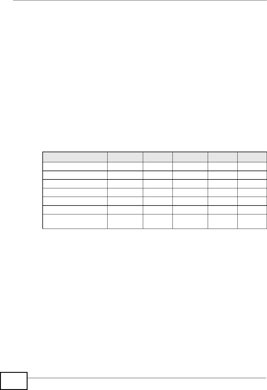
If both an AP and the wireless clients support WPA2 and you have an external
RADIUS server, use WPA2 for stronger data encryption. If you don't have an
external RADIUS server, you should use WPA2-PSK (WPA2-Pre-Shared Key) that
only requires a single (identical) password entered into each access point, wireless
gateway and wireless client. As long as the passwords match, a wireless client will
be granted access to a WLAN.
Table 125 Comparison of EAP Authentication Types
EAP-MD5 EAP-TLS EAP-TTLS PEAP LEAP
Mutual Authentication No Yes Yes Yes Yes
Certificate – Client No Yes Optional Optional No
Certificate – Server No Yes Yes Yes No
Dynamic Key Exchange No Yes Yes Yes Yes
Credential Integrity None Strong Strong Strong Moderate
Deployment Difficulty Easy Hard Moderate Moderate Moderate
Client Identity
Protection No No Yes Yes No
Company Confidential

Appendix CWireless LANs
User’s Guide 321
If the AP or the wireless clients do not support WPA2, just use WPA or WPA-PSK
depending on whether you have an external RADIUS server or not.
Select WEP only when the AP and/or wireless clients do not support WPA or WPA2.
WEP is less secure than WPA or WPA2.
Encryption
WPA improves data encryption by using Temporal Key Integrity Protocol (TKIP),
Message Integrity Check (MIC) and IEEE 802.1x. WPA2 also uses TKIP when
required for compatibility reasons, but offers stronger encryption than TKIP with
Advanced Encryption Standard (AES) in the Counter mode with Cipher block
chaining Message authentication code Protocol (CCMP).
TKIP uses 128-bit keys that are dynamically generated and distributed by the
authentication server. AES (Advanced Encryption Standard) is a block cipher that
uses a 256-bit mathematical algorithm called Rijndael. They both include a per-
packet key mixing function, a Message Integrity Check (MIC) named Michael, an
extended initialization vector (IV) with sequencing rules, and a re-keying
mechanism.
WPA and WPA2 regularly change and rotate the encryption keys so that the same
encryption key is never used twice.
The RADIUS server distributes a Pairwise Master Key (PMK) key to the AP that
then sets up a key hierarchy and management system, using the PMK to
dynamically generate unique data encryption keys to encrypt every data packet
that is wirelessly communicated between the AP and the wireless clients. This all
happens in the background automatically.
The Message Integrity Check (MIC) is designed to prevent an attacker from
capturing data packets, altering them and resending them. The MIC provides a
strong mathematical function in which the receiver and the transmitter each
compute and then compare the MIC. If they do not match, it is assumed that the
data has been tampered with and the packet is dropped.
By generating unique data encryption keys for every data packet and by creating
an integrity checking mechanism (MIC), with TKIP and AES it is more difficult to
decrypt data on a Wi-Fi network than WEP and difficult for an intruder to break
into the network.
The encryption mechanisms used for WPA(2) and WPA(2)-PSK are the same. The
only difference between the two is that WPA(2)-PSK uses a simple common
password, instead of user-specific credentials. The common-password approach
makes WPA(2)-PSK susceptible to brute-force password-guessing attacks but it’s
still an improvement over WEP as it employs a consistent, single, alphanumeric
password to derive a PMK which is used to generate unique temporal encryption
Company Confidential

Appendix CWireless LANs
User’s Guide
322
keys. This prevent all wireless devices sharing the same encryption keys. (a
weakness of WEP)
User Authentication
WPA and WPA2 apply IEEE 802.1x and Extensible Authentication Protocol (EAP) to
authenticate wireless clients using an external RADIUS database. WPA2 reduces
the number of key exchange messages from six to four (CCMP 4-way handshake)
and shortens the time required to connect to a network. Other WPA2
authentication features that are different from WPA include key caching and pre-
authentication. These two features are optional and may not be supported in all
wireless devices.
Key caching allows a wireless client to store the PMK it derived through a
successful authentication with an AP. The wireless client uses the PMK when it
tries to connect to the same AP and does not need to go with the authentication
process again.
Pre-authentication enables fast roaming by allowing the wireless client (already
connecting to an AP) to perform IEEE 802.1x authentication with another AP
before connecting to it.
Wireless Client WPA Supplicants
A wireless client supplicant is the software that runs on an operating system
instructing the wireless client how to use WPA. At the time of writing, the most
widely available supplicant is theWPA patch for Windows XP, Funk Software's
Odyssey client.
The Windows XP patch is a free download that adds WPA capability to Windows
XP's built-in "Zero Configuration" wireless client. However, you must run Windows
XP to use it.
WPA(2) with RADIUS Application Example
To set up WPA(2), you need the IP address of the RADIUS server, its port number
(default is 1812), and the RADIUS shared secret. A WPA(2) application example
with an external RADIUS server looks as follows. "A" is the RADIUS server. "DS" is
the distribution system.
1The AP passes the wireless client's authentication request to the RADIUS server.
2The RADIUS server then checks the user's identification against its database and
grants or denies network access accordingly.
3A 256-bit Pairwise Master Key (PMK) is derived from the authentication process by
the RADIUS server and the client.
Company Confidential
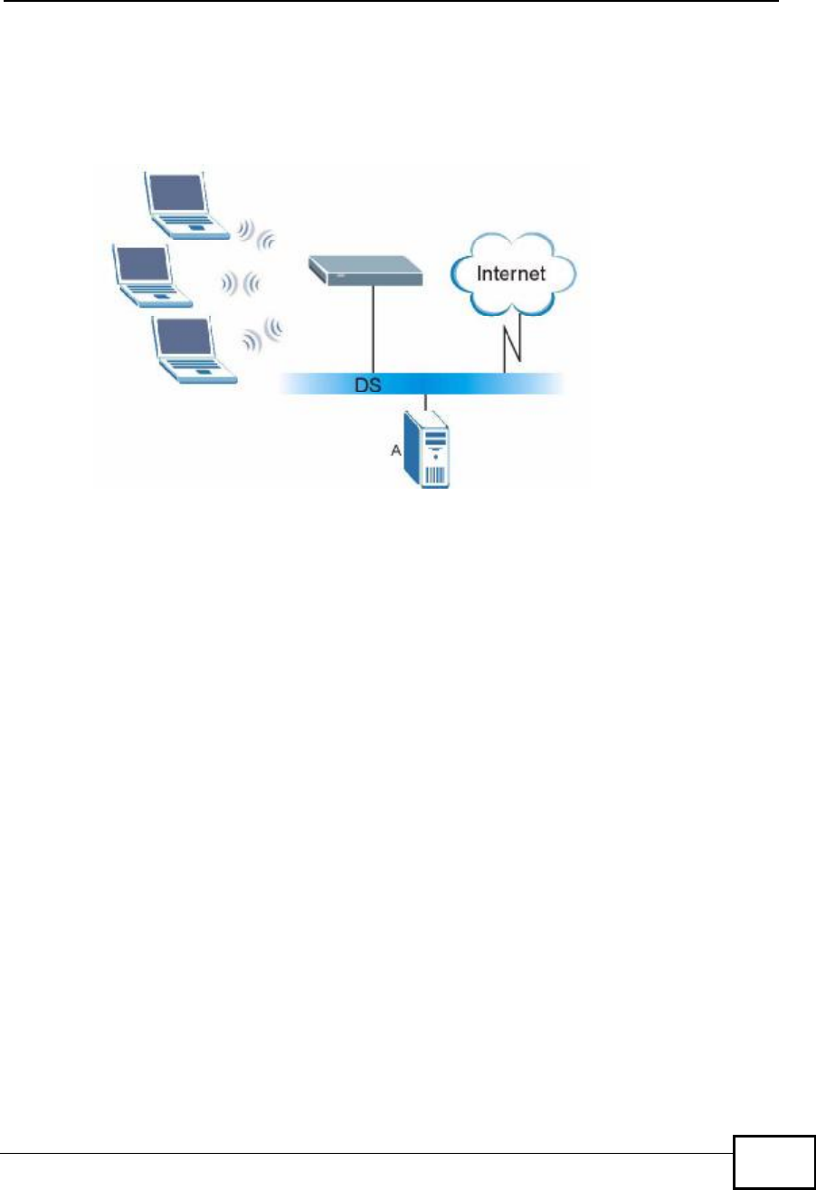
Appendix CWireless LANs
User’s Guide 323
4The RADIUS server distributes the PMK to the AP. The AP then sets up a key
hierarchy and management system, using the PMK to dynamically generate
unique data encryption keys. The keys are used to encrypt every data packet that
is wirelessly communicated between the AP and the wireless clients.
Figure 170 WPA(2) with RADIUS Application Example
WPA(2)-PSK Application Example
A WPA(2)-PSK application looks as follows.
1First enter identical passwords into the AP and all wireless clients. The Pre-Shared
Key (PSK) must consist of between 8 and 63 ASCII characters or 64 hexadecimal
characters (including spaces and symbols).
2The AP checks each wireless client's password and allows it to join the network
only if the password matches.
3The AP and wireless clients generate a common PMK (Pairwise Master Key). The
key itself is not sent over the network, but is derived from the PSK and the SSID.
Company Confidential
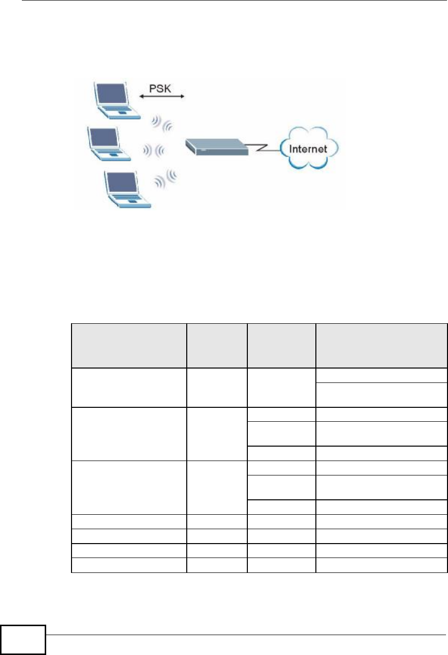
Appendix CWireless LANs
User’s Guide
324
4The AP and wireless clients use the TKIP or AES encryption process, the PMK and
information exchanged in a handshake to create temporal encryption keys. They
use these keys to encrypt data exchanged between them.
Figure 171 WPA(2)-PSK Authentication
Security Parameters Summary
Refer to this table to see what other security parameters you should configure for
each authentication method or key management protocol type. MAC address
filters are not dependent on how you configure these security features.
Table 126 Wireless Security Relational Matrix
AUTHENTICATION
METHOD/ KEY
MANAGEMENT
PROTOCOL
ENCRYPTIO
N METHOD ENTER
MANUAL KEY IEEE 802.1X
OpenNoneNoDisable
Enable without Dynamic WEP
Key
Open WEP No Enable with Dynamic WEP Key
Yes Enable without Dynamic WEP
Key
Yes Disable
Shared WEP No Enable with Dynamic WEP Key
Yes Enable without Dynamic WEP
Key
Yes Disable
WPA TKIP/AES No Enable
WPA-PSK TKIP/AES Yes Disable
WPA2 TKIP/AES No Enable
WPA2-PSK TKIP/AES Yes Disable
Company Confidential

Appendix CWireless LANs
User’s Guide 325
Antenna Overview
An antenna couples RF signals onto air. A transmitter within a wireless device
sends an RF signal to the antenna, which propagates the signal through the air.
The antenna also operates in reverse by capturing RF signals from the air.
Positioning the antennas properly increases the range and coverage area of a
wireless LAN.
Antenna Characteristics
Frequency
An antenna in the frequency of 2.4GHz (IEEE 802.11b and IEEE 802.11g) or 5GHz
(IEEE 802.11a) is needed to communicate efficiently in a wireless LAN
Radiation Pattern
A radiation pattern is a diagram that allows you to visualize the shape of the
antenna’s coverage area.
Antenna Gain
Antenna gain, measured in dB (decibel), is the increase in coverage within the RF
beam width. Higher antenna gain improves the range of the signal for better
communications.
For an indoor site, each 1 dB increase in antenna gain results in a range increase
of approximately 2.5%. For an unobstructed outdoor site, each 1dB increase in
gain results in a range increase of approximately 5%. Actual results may vary
depending on the network environment.
Antenna gain is sometimes specified in dBi, which is how much the antenna
increases the signal power compared to using an isotropic antenna. An isotropic
antenna is a theoretical perfect antenna that sends out radio signals equally well
in all directions. dBi represents the true gain that the antenna provides.
Company Confidential

Appendix CWireless LANs
User’s Guide
326
Types of Antennas for WLAN
There are two types of antennas used for wireless LAN applications.
•Omni-directional antennas send the RF signal out in all directions on a horizontal
plane. The coverage area is torus-shaped (like a donut) which makes these
antennas ideal for a room environment. With a wide coverage area, it is possible
to make circular overlapping coverage areas with multiple access points.
•Directional antennas concentrate the RF signal in a beam, like a flashlight does
with the light from its bulb. The angle of the beam determines the width of the
coverage pattern. Angles typically range from 20 degrees (very directional) to
120 degrees (less directional). Directional antennas are ideal for hallways and
outdoor point-to-point applications.
Positioning Antennas
In general, antennas should be mounted as high as practically possible and free of
obstructions. In point-to–point application, position both antennas at the same
height and in a direct line of sight to each other to attain the best performance.
For omni-directional antennas mounted on a table, desk, and so on, point the
antenna up. For omni-directional antennas mounted on a wall or ceiling, point the
antenna down. For a single AP application, place omni-directional antennas as
close to the center of the coverage area as possible.
For directional antennas, point the antenna in the direction of the desired
coverage area.
Company Confidential

User’s Guide 327
APPENDIX D
Pop-up Windows, JavaScripts
and Java Permissions
In order to use the web configurator you need to allow:
•Web browser pop-up windows from your device.
•JavaScripts (enabled by default).
•Java permissions (enabled by default).
Note: Internet Explorer 6 screens are used here. Screens for other Internet Explorer
versions may vary.
Internet Explorer Pop-up Blockers
You may have to disable pop-up blocking to log into your device.
Either disable pop-up blocking (enabled by default in Windows XP SP (Service
Pack) 2) or allow pop-up blocking and create an exception for your device’s IP
address.
Disable Pop-up Blockers
1In Internet Explorer, select Tools,Pop-up Blocker and then select Turn Off
Pop-up Blocker.
Figure 172 Pop-up Blocker
You can also check if pop-up blocking is disabled in the Pop-up Blocker section in
the Privacy tab.
Company Confidential
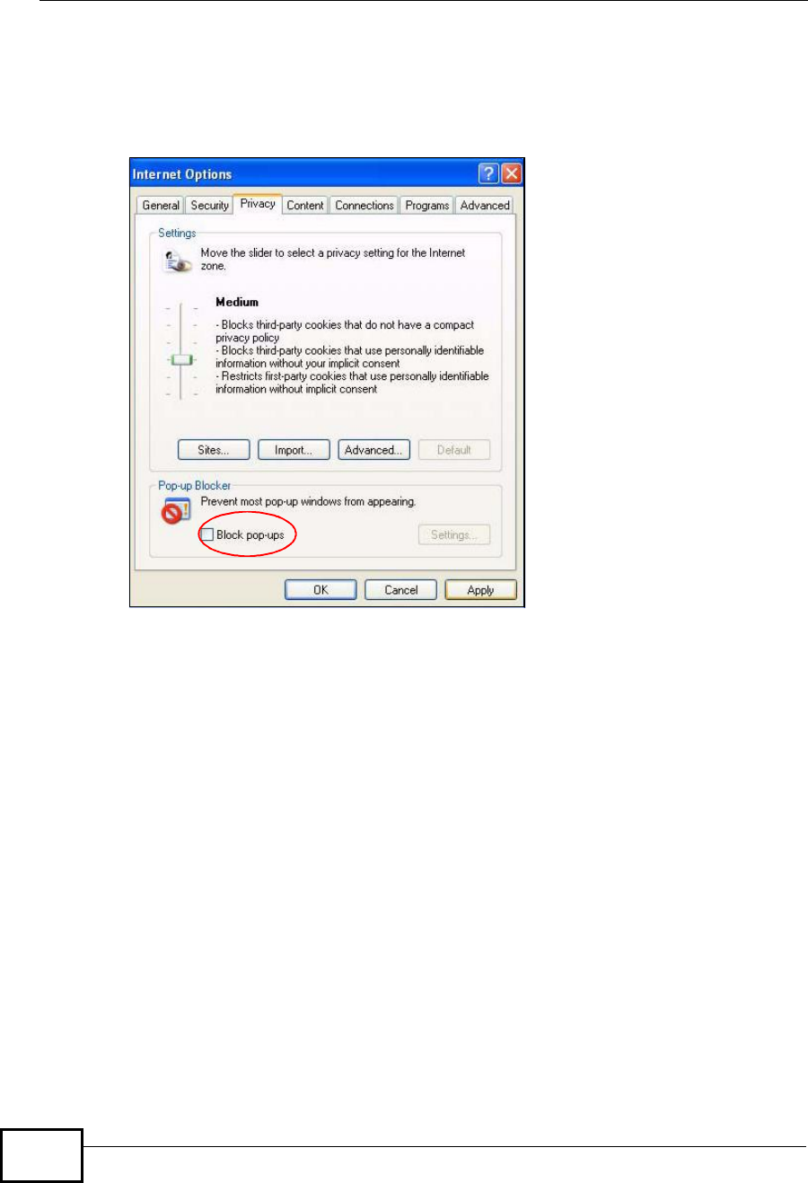
Appendix DPop-up Windows, JavaScripts and Java Permissions
User’s Guide
328
1In Internet Explorer, select Tools,Internet Options,Privacy.
2Clear the Block pop-ups check box in the Pop-up Blocker section of the screen.
This disables any web pop-up blockers you may have enabled.
Figure 173 Internet Options: Privacy
3Click Apply to save this setting.
Enable Pop-up Blockers with Exceptions
Alternatively, if you only want to allow pop-up windows from your device, see the
following steps.
1In Internet Explorer, select Tools,Internet Options and then the Privacy tab.
Company Confidential
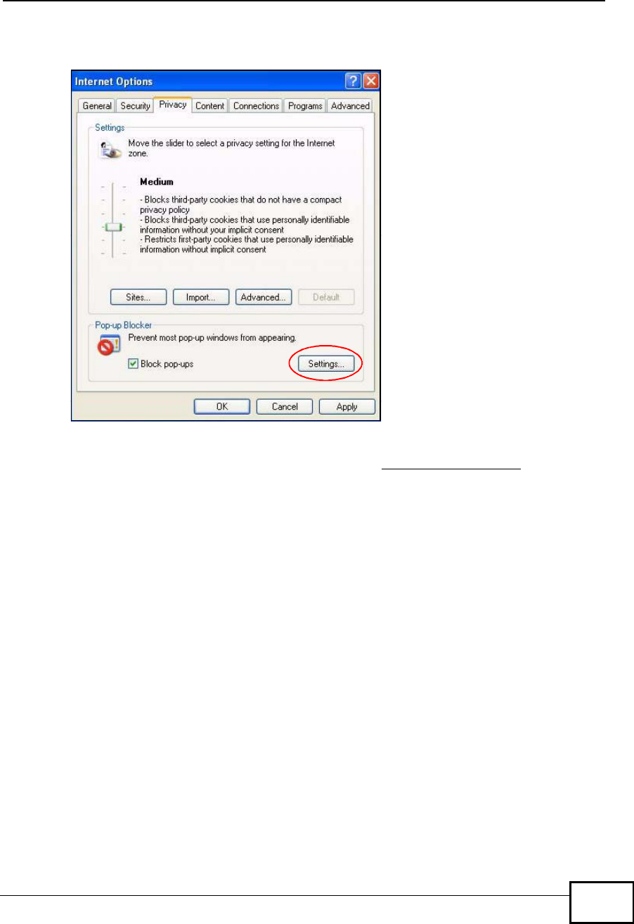
Appendix DPop-up Windows, JavaScripts and Java Permissions
User’s Guide 329
2Select Settings…to open the Pop-up Blocker Settings screen.
Figure 174 Internet Options: Privacy
3Type the IP address of your device (the web page that you do not want to have
blocked) with the prefix “http://”. For example, http://192.168.167.1.
Company Confidential
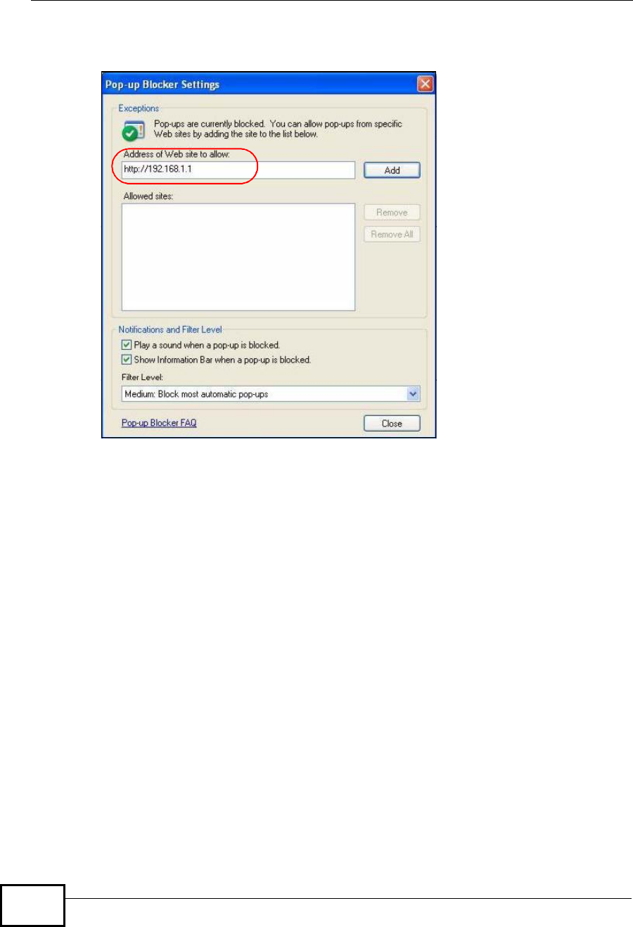
Appendix DPop-up Windows, JavaScripts and Java Permissions
User’s Guide
330
4Click Add to move the IP address to the list of Allowed sites.
Figure 175 Pop-up Blocker Settings
5Click Close to return to the Privacy screen.
6Click Apply to save this setting.
JavaScripts
If pages of the web configurator do not display properly in Internet Explorer,
check that JavaScripts are allowed.
Company Confidential
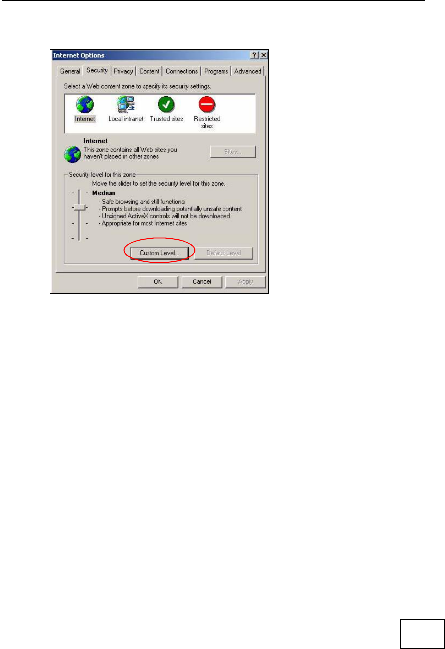
Appendix DPop-up Windows, JavaScripts and Java Permissions
User’s Guide 331
1In Internet Explorer, click Tools,Internet Options and then the Security tab.
Figure 176 Internet Options: Security
2Click the Custom Level... button.
3Scroll down to Scripting.
4Under Active scripting make sure that Enable is selected (the default).
5Under Scripting of Java applets make sure that Enable is selected (the
default).
Company Confidential
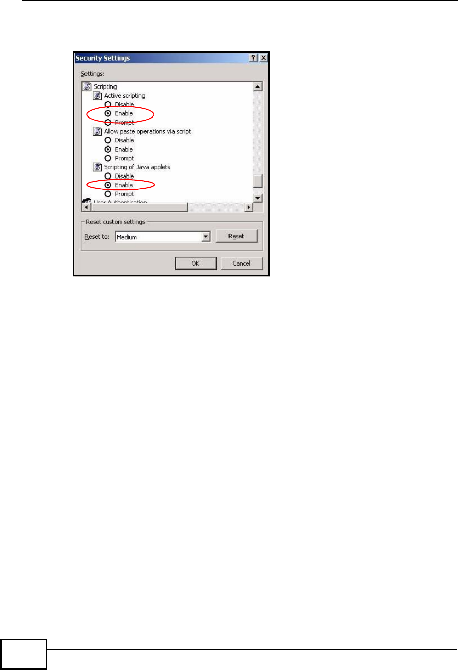
Appendix DPop-up Windows, JavaScripts and Java Permissions
User’s Guide
332
6Click OK to close the window.
Figure 177 Security Settings - Java Scripting
Java Permissions
1From Internet Explorer, click Tools,Internet Options and then the Security
tab.
2Click the Custom Level... button.
3Scroll down to Microsoft VM.
4Under Java permissions make sure that a safety level is selected.
Company Confidential
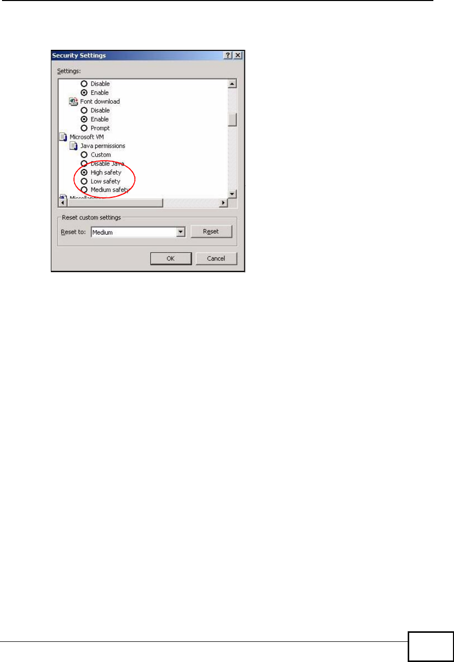
Appendix DPop-up Windows, JavaScripts and Java Permissions
User’s Guide 333
5Click OK to close the window.
Figure 178 Security Settings - Java
JAVA (Sun)
1From Internet Explorer, click Tools,Internet Options and then the Advanced
tab.
2Make sure that Use Java 2 for <applet> under Java (Sun) is selected.
Company Confidential
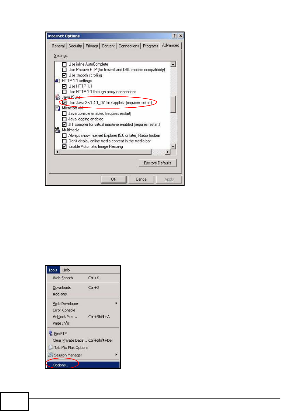
Appendix DPop-up Windows, JavaScripts and Java Permissions
User’s Guide
334
3Click OK to close the window.
Figure 179 Java (Sun)
Mozilla Firefox
Mozilla Firefox 2.0 screens are used here. Screens for other versions may vary.
You can enable Java, Javascripts and pop-ups in one screen. Click Tools, then
click Options in the screen that appears.
Figure 180 Mozilla Firefox: TOOLS > Options
Company Confidential
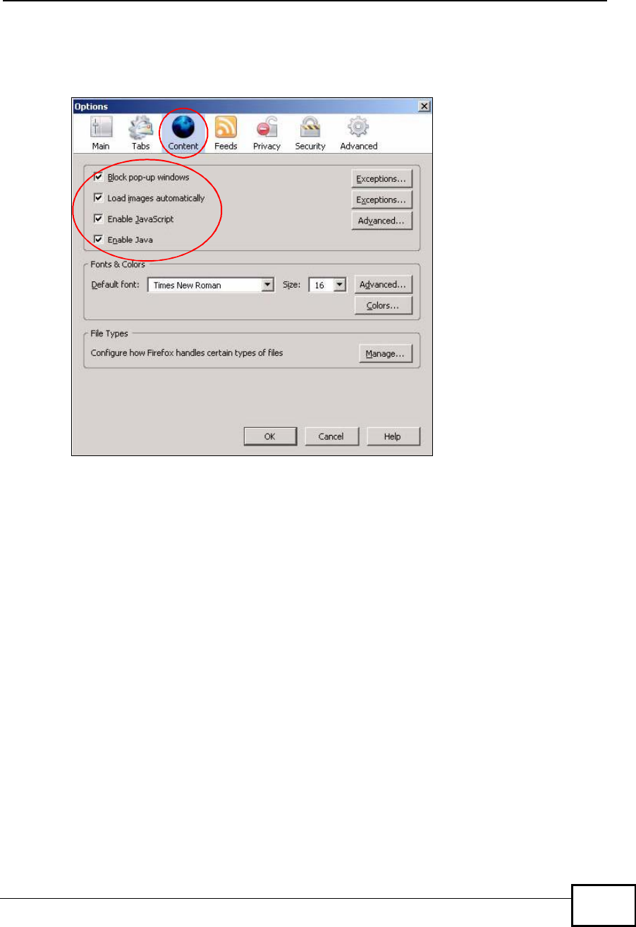
Appendix DPop-up Windows, JavaScripts and Java Permissions
User’s Guide 335
Click Content.to show the screen below. Select the check boxes as shown in the
following screen.
Figure 181 Mozilla Firefox Content Security
Company Confidential

Appendix DPop-up Windows, JavaScripts and Java Permissions
User’s Guide
336
Company Confidential

User’s Guide 337
APPENDIX E
IP Addresses and Subnetting
This appendix introduces IP addresses and subnet masks.
IP addresses identify individual devices on a network. Every networking device
(including computers, servers, routers, printers, etc.) needs an IP address to
communicate across the network. These networking devices are also known as
hosts.
Subnet masks determine the maximum number of possible hosts on a network.
You can also use subnet masks to divide one network into multiple sub-networks.
Introduction to IP Addresses
One part of the IP address is the network number, and the other part is the host
ID. In the same way that houses on a street share a common street name, the
hosts on a network share a common network number. Similarly, as each house
has its own house number, each host on the network has its own unique
identifying number - the host ID. Routers use the network number to send
packets to the correct network, while the host ID determines to which host on the
network the packets are delivered.
Structure
An IP address is made up of four parts, written in dotted decimal notation (for
example, 192.168.100.1). Each of these four parts is known as an octet. An octet
is an eight-digit binary number (for example 11000000, which is 192 in decimal
notation).
Therefore, each octet has a possible range of 00000000 to 11111111 in binary, or
0 to 255 in decimal.
Company Confidential
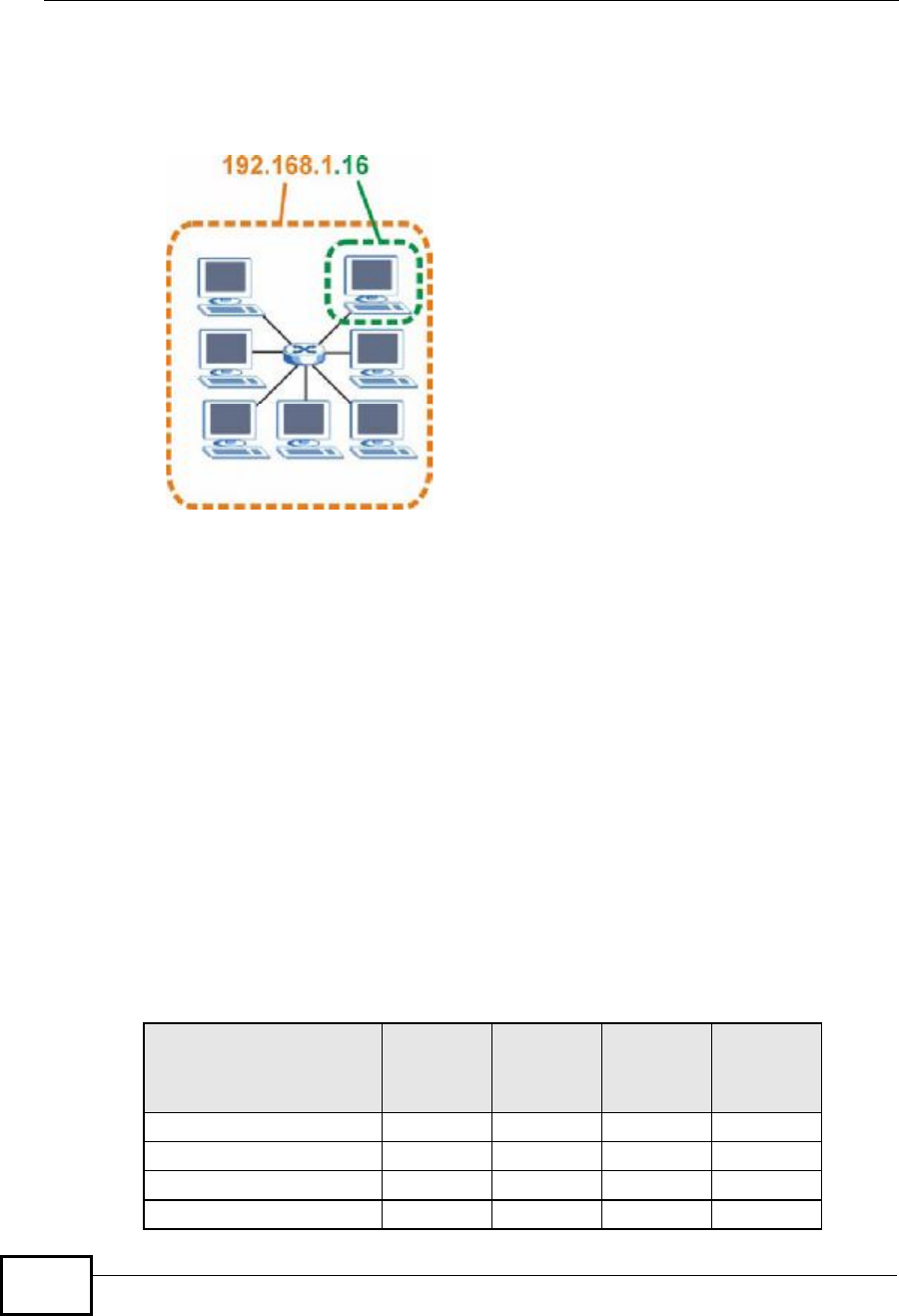
Appendix EIP Addresses and Subnetting
User’s Guide
338
The following figure shows an example IP address in which the first three octets
(192.168.1) are the network number, and the fourth octet (16) is the host ID.
Figure 182 Network Number and Host ID
How much of the IP address is the network number and how much is the host ID
varies according to the subnet mask.
Subnet Masks
A subnet mask is used to determine which bits are part of the network number,
and which bits are part of the host ID (using a logical AND operation). The term
“subnet” is short for “sub-network”.
A subnet mask has 32 bits. If a bit in the subnet mask is a “1” then the
corresponding bit in the IP address is part of the network number. If a bit in the
subnet mask is “0” then the corresponding bit in the IP address is part of the host
ID.
The following example shows a subnet mask identifying the network number (in
bold text) and host ID of an IP address (192.168.1.2 in decimal).
Table 127 IP Address Network Number and Host ID Example
1ST
OCTET:
(192)
2ND
OCTET:
(168)
3RD
OCTET:
(1)
4TH
OCTET
(2)
IP Address (Binary)11000000101010000000000100000010
Subnet Mask (Binary) 111111111111111111111111 00000000
Network Number 110000001010100000000001
Host ID00000010
Company Confidential

Appendix EIP Addresses and Subnetting
User’s Guide 339
By convention, subnet masks always consist of a continuous sequence of ones
beginning from the leftmost bit of the mask, followed by a continuous sequence of
zeros, for a total number of 32 bits.
Subnet masks can be referred to by the size of the network number part (the bits
with a “1” value). For example, an “8-bit mask” means that the first 8 bits of the
mask are ones and the remaining 24 bits are zeroes.
Subnet masks are expressed in dotted decimal notation just like IP addresses. The
following examples show the binary and decimal notation for 8-bit, 16-bit, 24-bit
and 29-bit subnet masks.
Network Size
The size of the network number determines the maximum number of possible
hosts you can have on your network. The larger the number of network number
bits, the smaller the number of remaining host ID bits.
An IP address with host IDs of all zeros is the IP address of the network
(192.168.1.0 with a 24-bit subnet mask, for example). An IP address with host
IDs of all ones is the broadcast address for that network (192.168.1.255 with a
24-bit subnet mask, for example).
As these two IP addresses cannot be used for individual hosts, calculate the
maximum number of possible hosts in a network as follows:
Table 128 Subnet Masks
BINARY
DECIMAL
1ST
OCTET 2ND
OCTET 3RD
OCTET 4TH
OCTET
8-bit mask 11111111 00000000 00000000 00000000 255.0.0.0
16-bit
mask 11111111 11111111 00000000 00000000 255.255.0.0
24-bit
mask 11111111 11111111 11111111 00000000 255.255.255.0
29-bit
mask 11111111 11111111 11111111 11111000 255.255.255.24
8
Table 129 Maximum Host Numbers
SUBNET MASK HOST ID SIZE MAXIMUM NUMBER OF
HOSTS
8 bits255.0.0.024 bits2
24 – 216777214
16 bits255.255.0.016 bits2
16 – 265534
24 bits255.255.255.08 bits2
8
– 2254
29 bits255.255.255.2
48 3 bits2
3
– 26
Company Confidential

Appendix EIP Addresses and Subnetting
User’s Guide
340
Notation
Since the mask is always a continuous number of ones beginning from the left,
followed by a continuous number of zeros for the remainder of the 32 bit mask,
you can simply specify the number of ones instead of writing the value of each
octet. This is usually specified by writing a “/” followed by the number of bits in
the mask after the address.
For example, 192.1.1.0 /25 is equivalent to saying 192.1.1.0 with subnet mask
255.255.255.128.
The following table shows some possible subnet masks using both notations.
Subnetting
You can use subnetting to divide one network into multiple sub-networks. In the
following example a network administrator creates two sub-networks to isolate a
group of servers from the rest of the company network for security reasons.
In this example, the company network address is 192.168.1.0. The first three
octets of the address (192.168.1) are the network number, and the remaining
octet is the host ID, allowing a maximum of 28 – 2 or 254 possible hosts.
Table 130 Alternative Subnet Mask Notation
SUBNET
MASK ALTERNATIVE
NOTATION LAST OCTET
(BINARY) LAST OCTET
(DECIMAL)
255.255.255.0 /24 0000 0000 0
255.255.255.12
8/25 1000 0000 128
255.255.255.19
2/26 1100 0000 192
255.255.255.22
4/27 1110 0000 224
255.255.255.24
0/28 1111 0000 240
255.255.255.24
8/29 1111 1000 248
255.255.255.25
2/30 1111 1100 252
Company Confidential
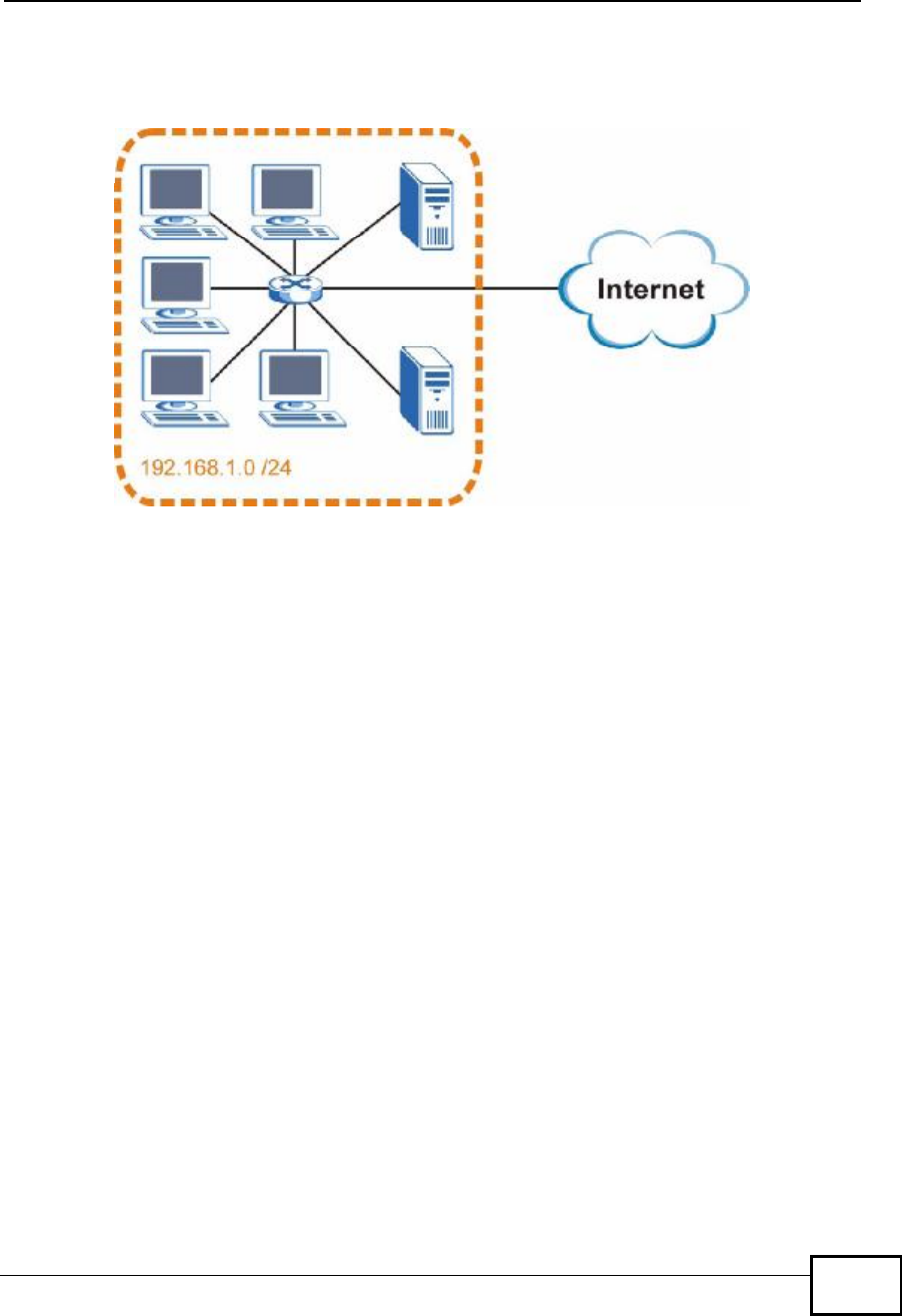
Appendix EIP Addresses and Subnetting
User’s Guide 341
The following figure shows the company network before subnetting.
Figure 183 Subnetting Example: Before Subnetting
You can “borrow” one of the host ID bits to divide the network 192.168.1.0 into
two separate sub-networks. The subnet mask is now 25 bits (255.255.255.128 or
/25).
The “borrowed” host ID bit can have a value of either 0 or 1, allowing two
subnets; 192.168.1.0 /25 and 192.168.100.128 /25.
Company Confidential
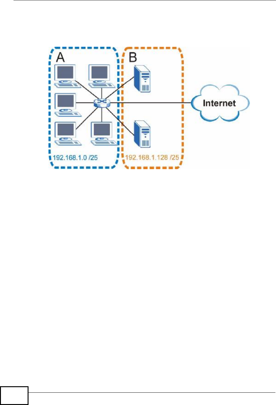
Appendix EIP Addresses and Subnetting
User’s Guide
342
The following figure shows the company network after subnetting. There are now
two sub-networks, A and B.
Figure 184 Subnetting Example: After Subnetting
In a 25-bit subnet the host ID has 7 bits, so each sub-network has a maximum of
27 – 2 or 126 possible hosts (a host ID of all zeroes is the subnet’s address itself,
all ones is the subnet’s broadcast address).
192.168.1.0 with mask 255.255.255.128 is subnet A itself, and 192.168.100.127
with mask 255.255.255.128 is its broadcast address. Therefore, the lowest IP
address that can be assigned to an actual host for subnet A is 192.168.100.1 and
the highest is 192.168.100.126.
Similarly, the host ID range for subnet B is 192.168.100.129 to 192.168.1.254.
Example: Four Subnets
The previous example illustrated using a 25-bit subnet mask to divide a 24-bit
address into two subnets. Similarly, to divide a 24-bit address into four subnets,
you need to “borrow” two host ID bits to give four possible combinations (00, 01,
10 and 11). The subnet mask is 26 bits
(11111111.11111111.11111111.11000000) or 255.255.255.192.
Company Confidential

Appendix EIP Addresses and Subnetting
User’s Guide 343
Each subnet contains 6 host ID bits, giving 26 - 2 or 62 hosts for each subnet (a
host ID of all zeroes is the subnet itself, all ones is the subnet’s broadcast
address).
Table 131 Subnet 1
IP/SUBNET MASK NETWORK NUMBER LAST OCTET BIT
VALUE
IP Address (Decimal) 192.168.1. 0
IP Address (Binary) 11000000.10101000.00000001. 00000000
Subnet Mask (Binary) 11111111.11111111.11111111. 11000000
Subnet Address:
192.168.1.0 Lowest Host ID: 192.168.100.1
Broadcast Address:
192.168.1.63 Highest Host ID: 192.168.1.62
Table 132 Subnet 2
IP/SUBNET MASK NETWORK NUMBER LAST OCTET BIT
VALUE
IP Address 192.168.1. 64
IP Address (Binary) 11000000.10101000.00000001. 01000000
Subnet Mask (Binary) 11111111.11111111.11111111. 11000000
Subnet Address:
192.168.1.64 Lowest Host ID: 192.168.1.65
Broadcast Address:
192.168.100.127 Highest Host ID: 192.168.100.126
Table 133 Subnet 3
IP/SUBNET MASK NETWORK NUMBER LAST OCTET BIT
VALUE
IP Address 192.168.1. 128
IP Address (Binary) 11000000.10101000.00000001. 10000000
Subnet Mask (Binary) 11111111.11111111.11111111. 11000000
Subnet Address:
192.168.100.128 Lowest Host ID: 192.168.100.129
Broadcast Address:
192.168.100.191 Highest Host ID: 192.168.100.190
Table 134 Subnet 4
IP/SUBNET MASK NETWORK NUMBER LAST OCTET BIT
VALUE
IP Address 192.168.1. 192
IP Address (Binary) 11000000.10101000.00000001
.11000000
Subnet Mask (Binary) 11111111.11111111.11111111
.11000000
Company Confidential
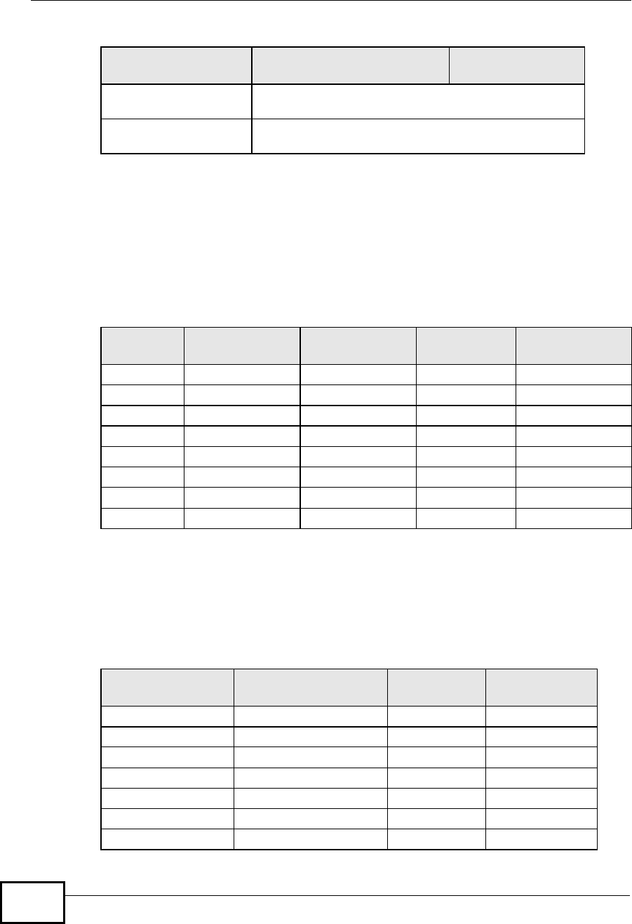
Appendix EIP Addresses and Subnetting
User’s Guide
344
Example: Eight Subnets
Similarly, use a 27-bit mask to create eight subnets (000, 001, 010, 011, 100,
101, 110 and 111).
The following table shows IP address last octet values for each subnet.
Subnet Planning
The following table is a summary for subnet planning on a network with a 24-bit
network number.
Subnet Address:
192.168.100.192 Lowest Host ID: 192.168.100.193
Broadcast Address:
192.168.1.255 Highest Host ID: 192.168.1.254
Table 134 Subnet 4 (continued)
IP/SUBNET MASK NETWORK NUMBER LAST OCTET BIT
VALUE
Table 135 Eight Subnets
SUBNET SUBNET
ADDRESS FIRST ADDRESS LAST
ADDRESS BROADCAST
ADDRESS
10130 31
2 32 33 62 63
3 64 65 94 95
4 96 97 126 127
5 128 129 158 159
6 160 161 190 191
7 192 193 222 223
8 224 225 254 255
Table 136 24-bit Network Number Subnet Planning
NO. “BORROWED”
HOST BITS SUBNET MASK NO. SUBNETS NO. HOSTS PER
SUBNET
1255.255.255.128 (/25) 2 126
2 255.255.255.192 (/26) 4 62
3 255.255.255.224 (/27) 8 30
4 255.255.255.240 (/28) 16 14
5 255.255.255.248 (/29) 32 6
6 255.255.255.252 (/30) 64 2
7 255.255.255.254 (/31) 128 1
Company Confidential

Appendix EIP Addresses and Subnetting
User’s Guide 345
The following table is a summary for subnet planning on a network with a 16-bit
network number.
Configuring IP Addresses
Where you obtain your network number depends on your particular situation. If
the ISP or your network administrator assigns you a block of registered IP
addresses, follow their instructions in selecting the IP addresses and the subnet
mask.
If the ISP did not explicitly give you an IP network number, then most likely you
have a single user account and the ISP will assign you a dynamic IP address when
the connection is established. If this is the case, it is recommended that you select
a network number from 192.168.0.0 to 192.168.255.0. The Internet Assigned
Number Authority (IANA) reserved this block of addresses specifically for private
use; please do not use any other number unless you are told otherwise. You must
also enable Network Address Translation (NAT) on the WiMAX Device.
Once you have decided on the network number, pick an IP address for your
WiMAX Device that is easy to remember (for instance, 192.168.100.1) but make
sure that no other device on your network is using that IP address.
The subnet mask specifies the network number portion of an IP address. Your
WiMAX Device will compute the subnet mask automatically based on the IP
Table 137 16-bit Network Number Subnet Planning
NO. “BORROWED”
HOST BITS SUBNET MASK NO.
SUBNETS NO. HOSTS PER
SUBNET
1255.255.128.0 (/17) 2 32766
2 255.255.192.0 (/18) 4 16382
3 255.255.224.0 (/19) 8 8190
4255.255.240.0 (/20) 16 4094
5255.255.248.0 (/21) 32 2046
6255.255.252.0 (/22) 64 1022
7255.255.254.0 (/23) 128 510
8 255.255.255.0 (/24) 256 254
9 255.255.255.128 (/25) 512 126
10 255.255.255.192 (/26) 1024 62
11 255.255.255.224 (/27) 2048 30
12 255.255.255.240 (/28) 4096 14
13 255.255.255.248 (/29) 8192 6
14 255.255.255.252 (/30) 16384 2
15 255.255.255.254 (/31) 32768 1
Company Confidential

Appendix EIP Addresses and Subnetting
User’s Guide
346
address that you entered. You don't need to change the subnet mask computed
by the WiMAX Device unless you are instructed to do otherwise.
Private IP Addresses
Every machine on the Internet must have a unique address. If your networks are
isolated from the Internet (running only between two branch offices, for example)
you can assign any IP addresses to the hosts without problems. However, the
Internet Assigned Numbers Authority (IANA) has reserved the following three
blocks of IP addresses specifically for private networks:
•10.0.0.0 — 10.255.255.255
•172.16.0.0 — 172.31.255.255
•192.168.0.0 — 192.168.255.255
You can obtain your IP address from the IANA, from an ISP, or it can be assigned
from a private network. If you belong to a small organization and your Internet
access is through an ISP, the ISP can provide you with the Internet addresses for
your local networks. On the other hand, if you are part of a much larger
organization, you should consult your network administrator for the appropriate IP
addresses.
Regardless of your particular situation, do not create an arbitrary IP address;
always follow the guidelines above. For more information on address assignment,
please refer to RFC 1597, Address Allocation for Private Internets and RFC 1466,
Guidelines for Management of IP Address Space.
IP Address Conflicts
Each device on a network must have a unique IP address. Devices with duplicate
IP addresses on the same network will not be able to access the Internet or other
resources. The devices may also be unreachable through the network.
Conflicting Computer IP Addresses Example
More than one device can not use the same IP address. In the following example
computer Ahas a static (or fixed) IP address that is the same as the IP address
that a DHCP server assigns to computer B which is a DHCP client. Neither can
access the Internet. This problem can be solved by assigning a different static IP
Company Confidential
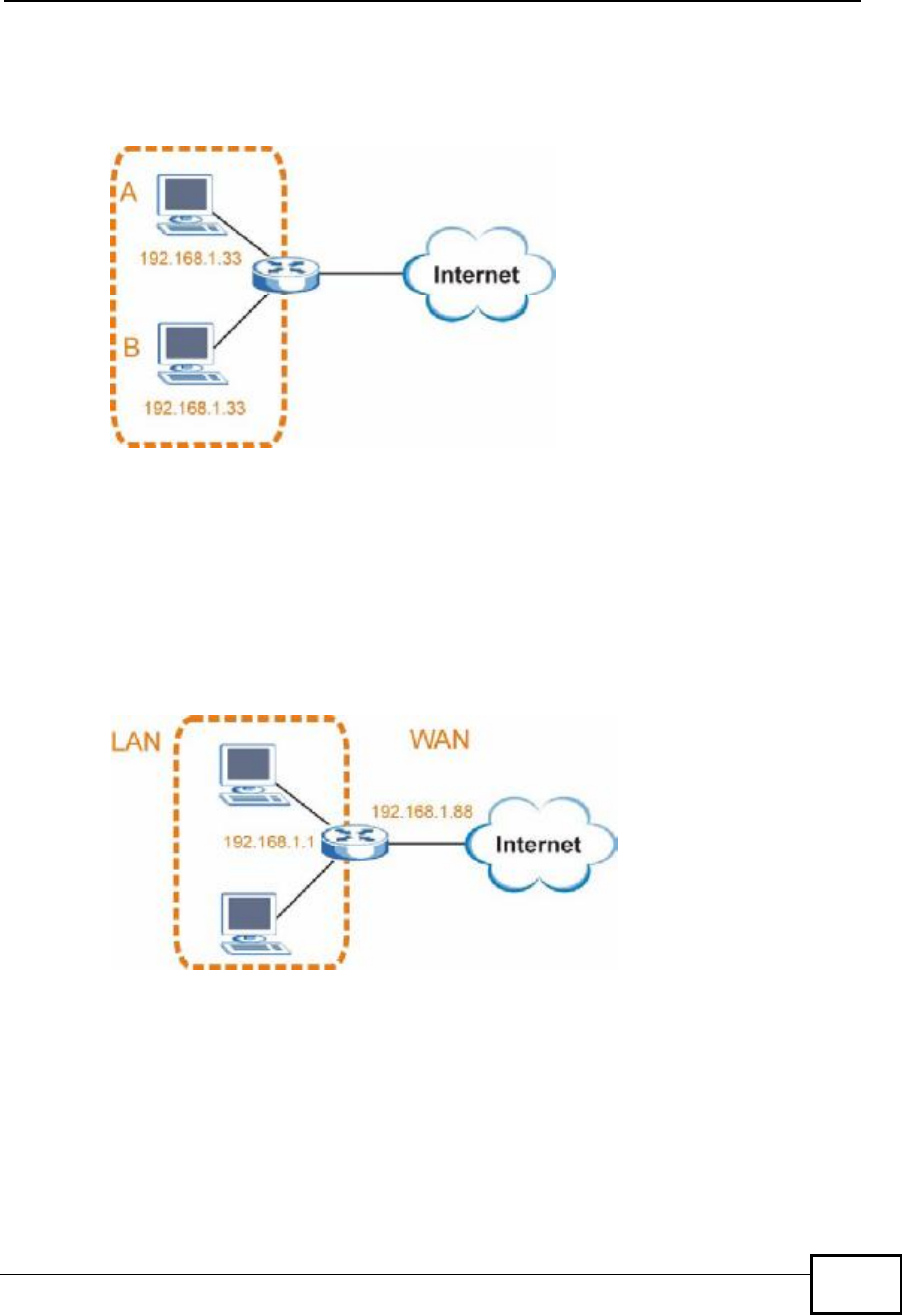
Appendix EIP Addresses and Subnetting
User’s Guide 347
address to computer A or setting computer A to obtain an IP address
automatically.
Figure 185 Conflicting Computer IP Addresses Example
Conflicting Router IP Addresses Example
Since a router connects different networks, it must have interfaces using different
network numbers. For example, if a router is set between a LAN and the Internet
(WAN), the router’s LAN and WAN addresses must be on different subnets. In the
following example, the LAN and WAN are on the same subnet. The LAN computers
cannot access the Internet because the router cannot route between networks.
Figure 186 Conflicting Computer IP Addresses Example
Conflicting Computer and Router IP Addresses Example
More than one device can not use the same IP address. In the following example,
the computer and the router’s LAN port both use 192.168.100.1 as the IP address.
Company Confidential
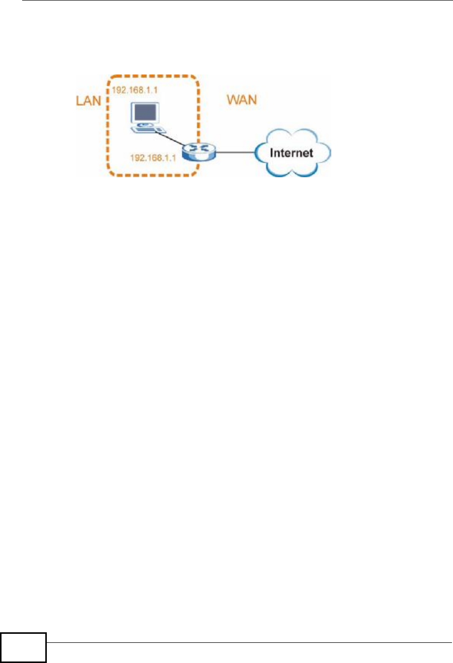
Appendix EIP Addresses and Subnetting
User’s Guide
348
The computer cannot access the Internet. This problem can be solved by
assigning a different IP address to the computer or the router’s LAN port.
Figure 187 Conflicting Computer and Router IP Addresses Example
Company Confidential

User’s Guide 349
APPENDIX F
Importing Certificates
This appendix shows you how to import public key certificates into your web
browser.
Public key certificates are used by web browsers to ensure that a secure web site
is legitimate. When a certificate authority such as VeriSign, Comodo, or Network
Solutions, to name a few, receives a certificate request from a website operator,
they confirm that the web domain and contact information in the request match
those on public record with a domain name registrar. If they match, then the
certificate is issued to the website operator, who then places it on the site to be
issued to all visiting web browsers to let them know that the site is legitimate.
Many ZyXEL products, such as the NSA-2401, issue their own public key
certificates. These can be used by web browsers on a LAN or WAN to verify that
they are in fact connecting to the legitimate device and not one masquerading as
it. However, because the certificates were not issued by one of the several
organizations officially recognized by the most common web browsers, you will
need to import the ZyXEL-created certificate into your web browser and flag that
certificate as a trusted authority.
Note: You can see if you are browsing on a secure website if the URL in your web
browser’s address bar begins with https:// or there is a sealed padlock
icon () somewhere in the main browser window (not all browsers show the
padlock in the same location.)
In this appendix, you can import a public key certificate for:
•Internet Explorer on page 350
•Firefox on page 360
•Opera on page 366
•Konqueror on page 374
Company Confidential
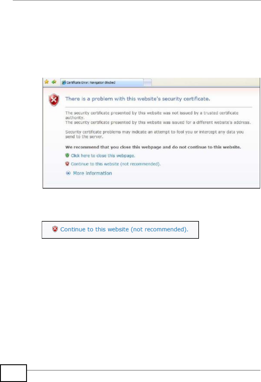
Appendix FImporting Certificates
User’s Guide
350
Internet Explorer
The following example uses Microsoft Internet Explorer 7 on Windows XP
Professional; however, they can also apply to Internet Explorer on Windows Vista.
1If your device’s web configurator is set to use SSL certification, then the first time
you browse to it you are presented with a certification error.
Figure 188 Internet Explorer 7: Certification Error
2Click Continue to this website (not recommended).
Figure 189 Internet Explorer 7: Certification Error
Company Confidential
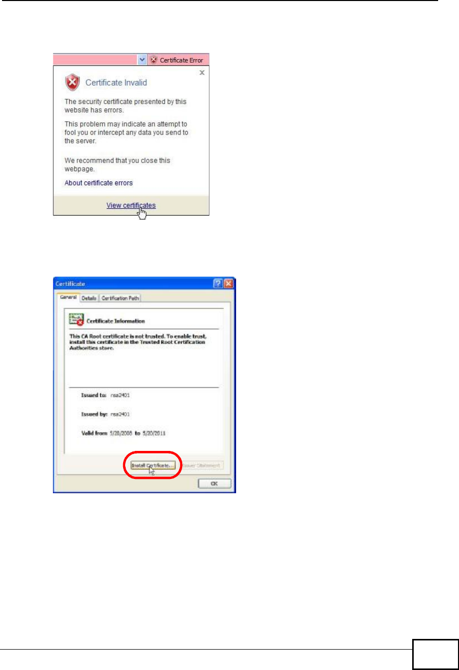
Appendix FImporting Certificates
User’s Guide 351
3In the Address Bar, click Certificate Error > View certificates.
Figure 190 Internet Explorer 7: Certificate Error
4In the Certificate dialog box, click Install Certificate.
Figure 191 Internet Explorer 7: Certificate
Company Confidential
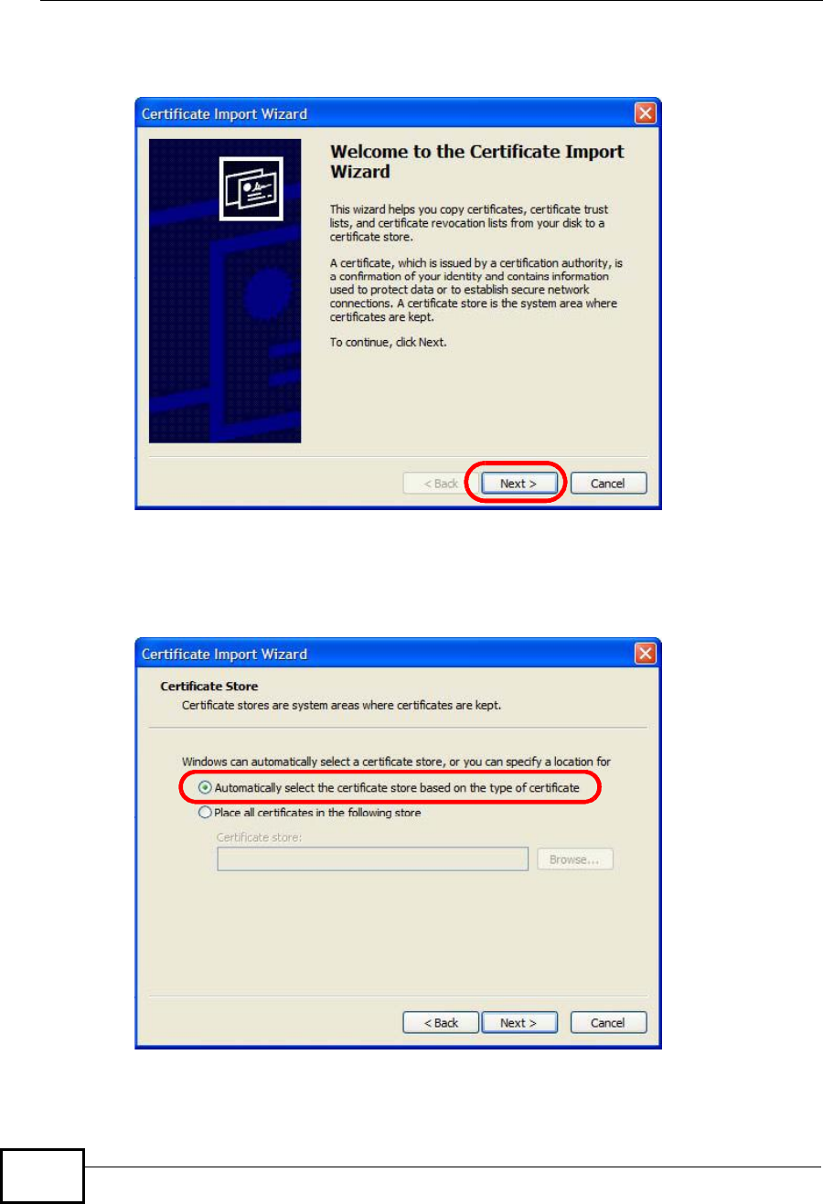
Appendix FImporting Certificates
User’s Guide
352
5In the Certificate Import Wizard, click Next.
Figure 192 Internet Explorer 7: Certificate Import Wizard
6If you want Internet Explorer to Automatically select certificate store based
on the type of certificate, click Next again and then go to step 9.
Figure 193 Internet Explorer 7: Certificate Import Wizard
Company Confidential
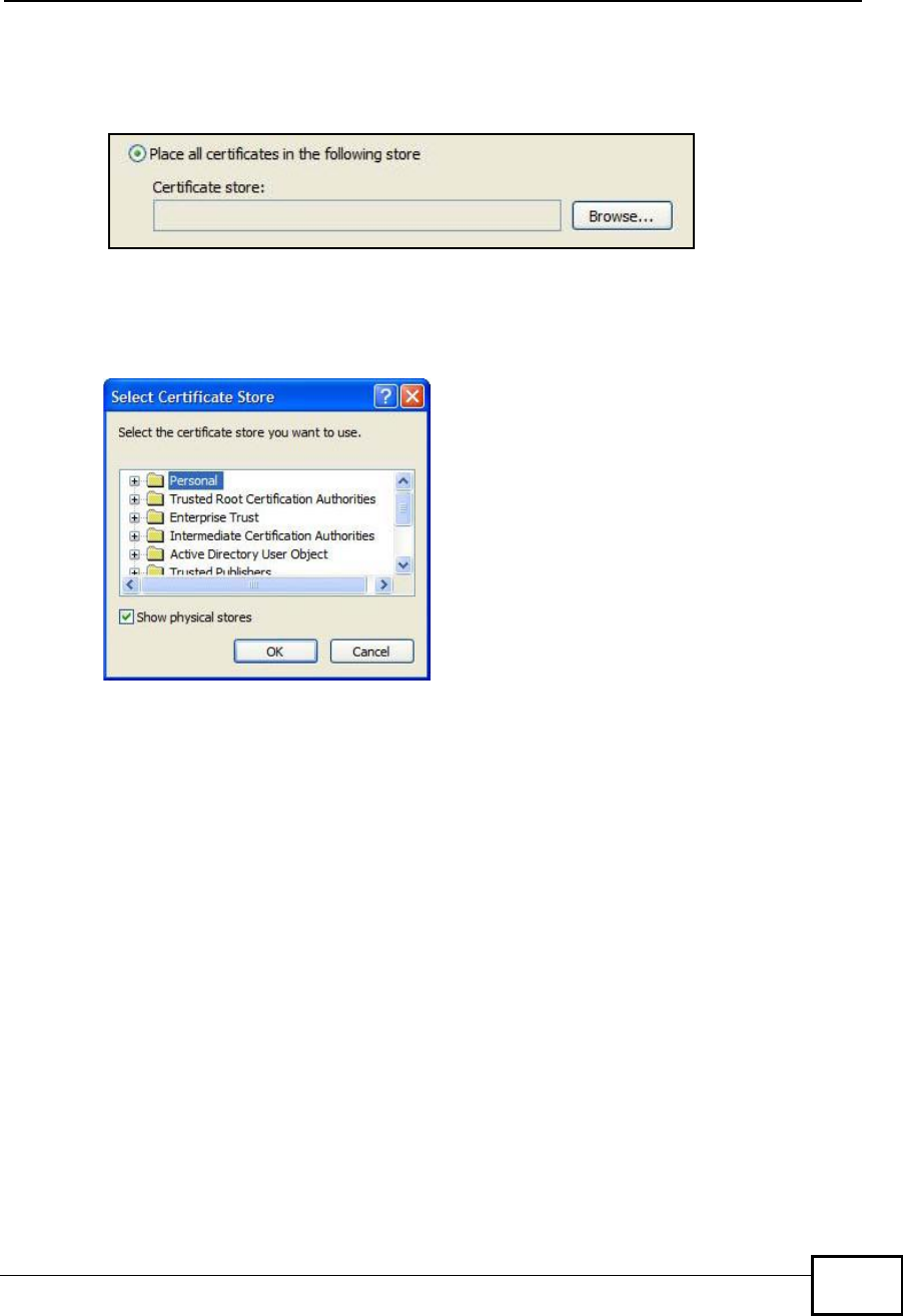
Appendix FImporting Certificates
User’s Guide 353
7Otherwise, select Place all certificates in the following store and then click
Browse.
Figure 194 Internet Explorer 7: Certificate Import Wizard
8In the Select Certificate Store dialog box, choose a location in which to save the
certificate and then click OK.
Figure 195 Internet Explorer 7: Select Certificate Store
Company Confidential

Appendix FImporting Certificates
User’s Guide
354
9In the Completing the Certificate Import Wizard screen, click Finish.
Figure 196 Internet Explorer 7: Certificate Import Wizard
10 If you are presented with another Security Warning, click Yes.
Figure 197 Internet Explorer 7: Security Warning
Company Confidential
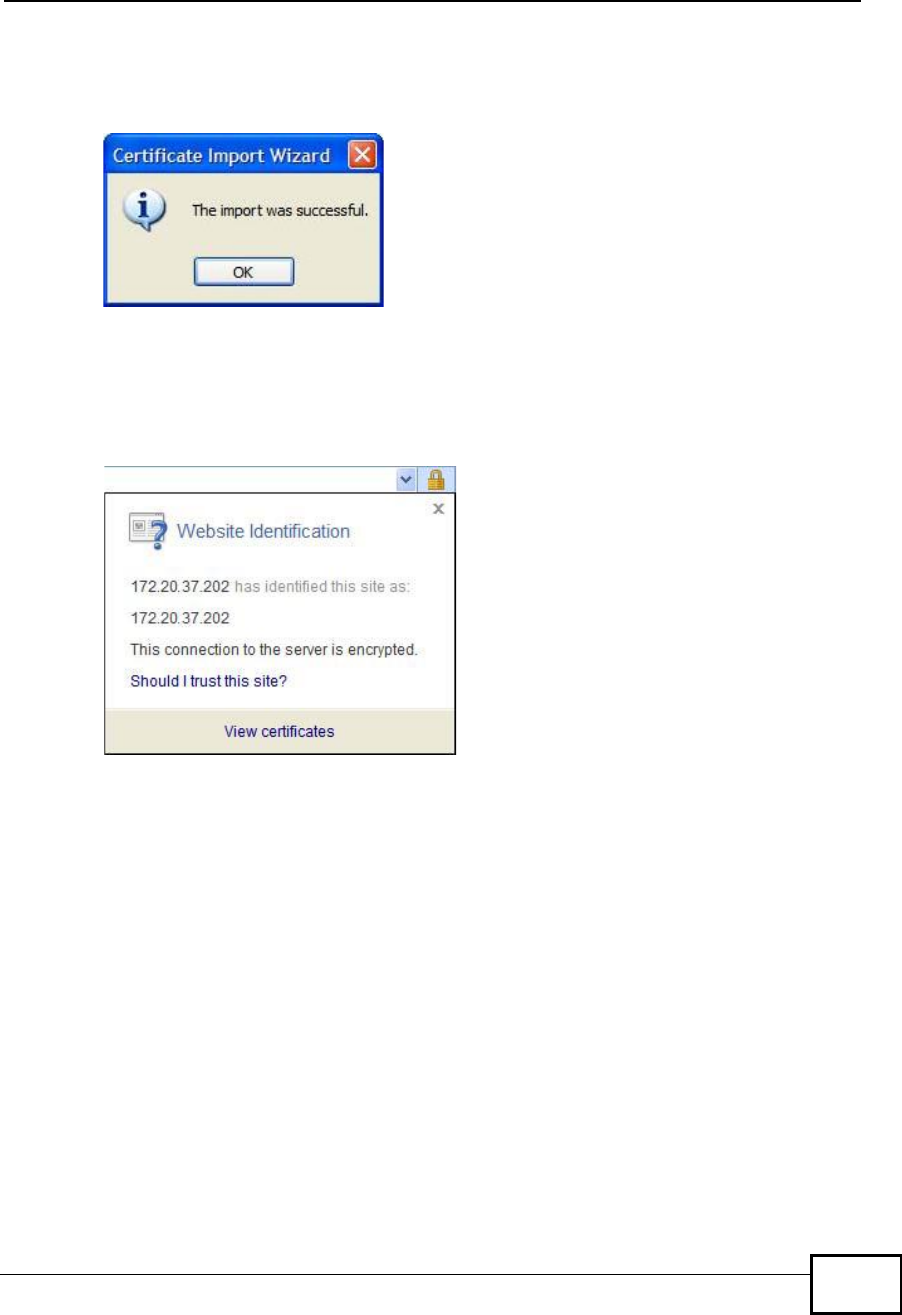
Appendix FImporting Certificates
User’s Guide 355
11 Finally, click OK when presented with the successful certificate installation
message.
Figure 198 Internet Explorer 7: Certificate Import Wizard
12 The next time you start Internet Explorer and go to a ZyXEL web configurator
page, a sealed padlock icon appears in the address bar. Click it to view the page’s
Website Identification information.
Figure 199 Internet Explorer 7: Website Identification
Company Confidential
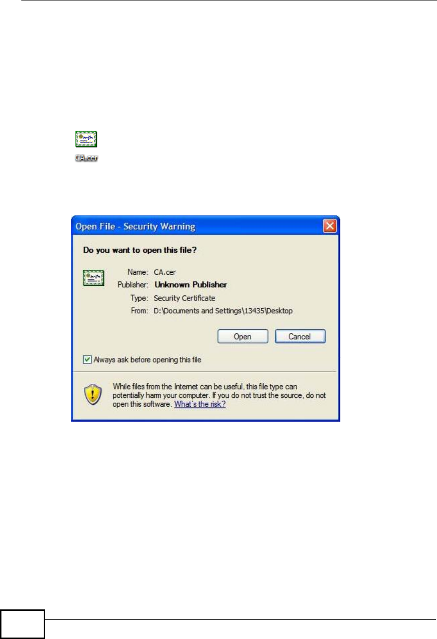
Appendix FImporting Certificates
User’s Guide
356
Installing a Stand-Alone Certificate File in Internet Explorer
Rather than browsing to a ZyXEL web configurator and installing a public key
certificate when prompted, you can install a stand-alone certificate file if one has
been issued to you.
1Double-click the public key certificate file.
Figure 200 Internet Explorer 7: Public Key Certificate File
2In the security warning dialog box, click Open.
Figure 201 Internet Explorer 7: Open File - Security Warning
3Refer to steps 4-12 in the Internet Explorer procedure beginning on page350 to
complete the installation process.
Company Confidential
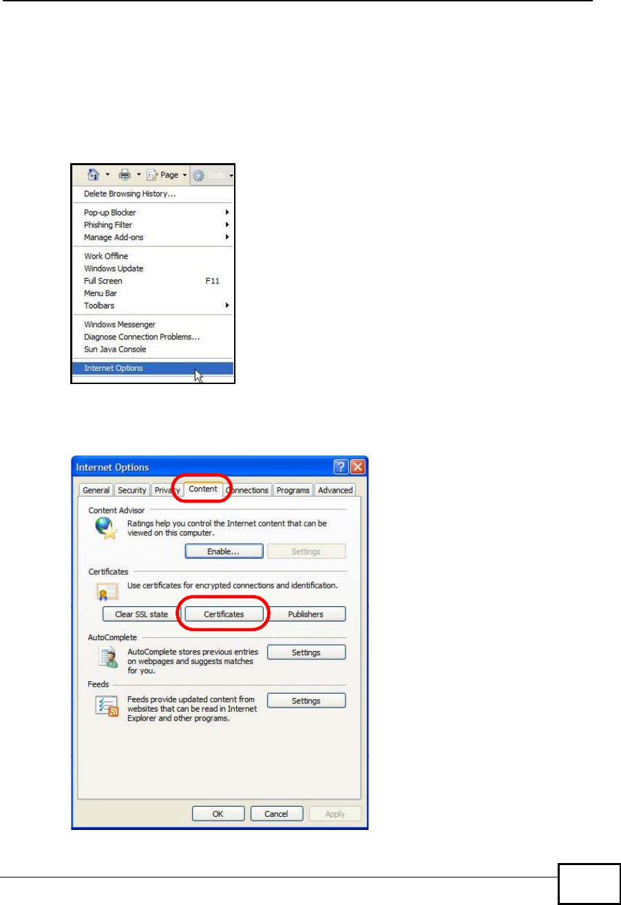
Appendix FImporting Certificates
User’s Guide 357
Removing a Certificate in Internet Explorer
This section shows you how to remove a public key certificate in Internet Explorer
7.
1Open Internet Explorer and click TOOLS >Internet Options.
Figure 202 Internet Explorer 7: Tools Menu
2In the Internet Options dialog box, click Content >Certificates.
Figure 203 Internet Explorer 7: Internet Options
Company Confidential
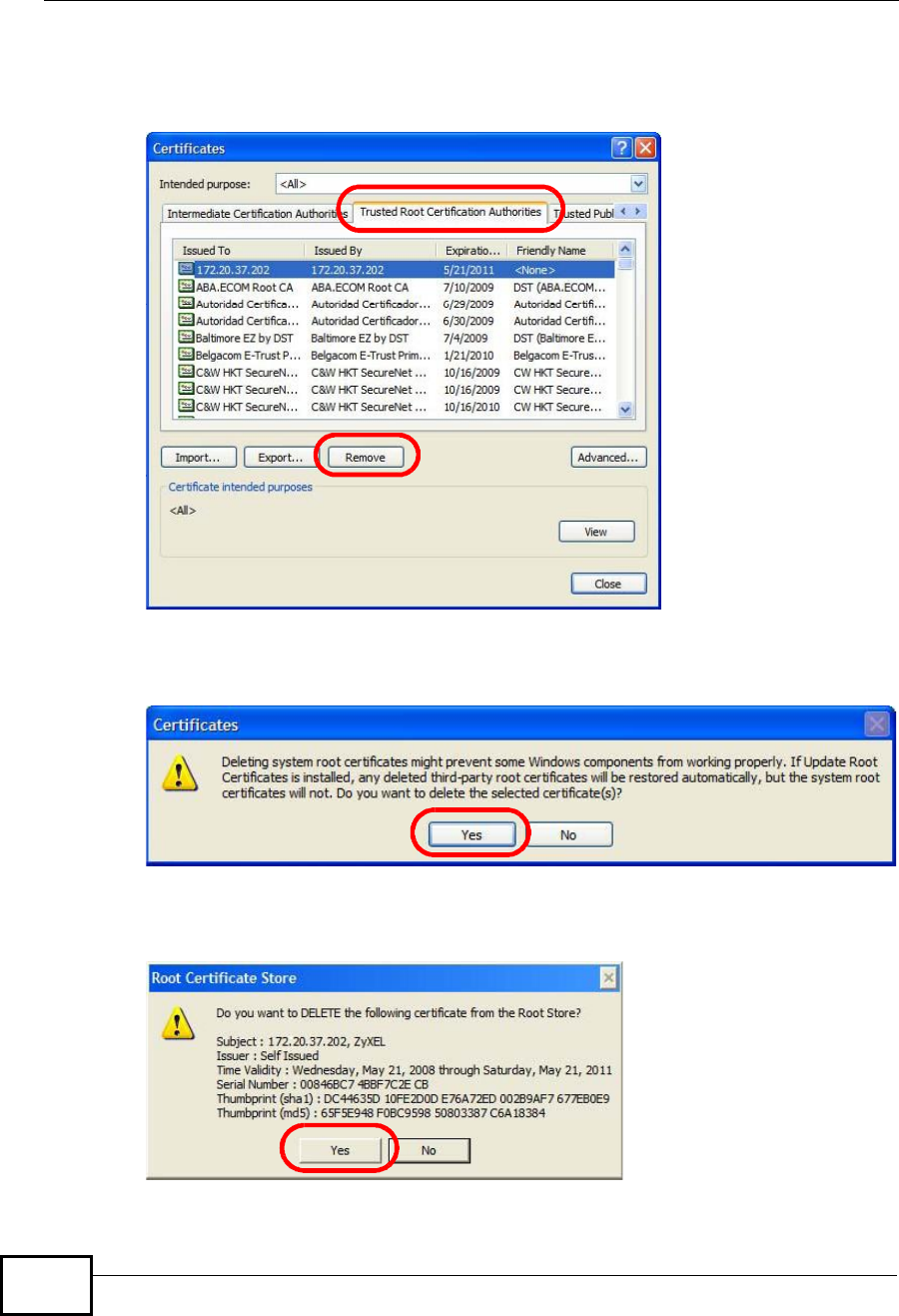
Appendix FImporting Certificates
User’s Guide
358
3In the Certificates dialog box, click the Trusted Root Certificates Authorities
tab, select the certificate that you want to delete, and then click Remove.
Figure 204 Internet Explorer 7: Certificates
4In the Certificates confirmation, click Yes.
Figure 205 Internet Explorer 7: Certificates
5In the Root Certificate Store dialog box, click Yes.
Figure 206 Internet Explorer 7: Root Certificate Store
Company Confidential

Appendix FImporting Certificates
User’s Guide 359
6The next time you go to the web site that issued the public key certificate you just
removed, a certification error appears.
Company Confidential
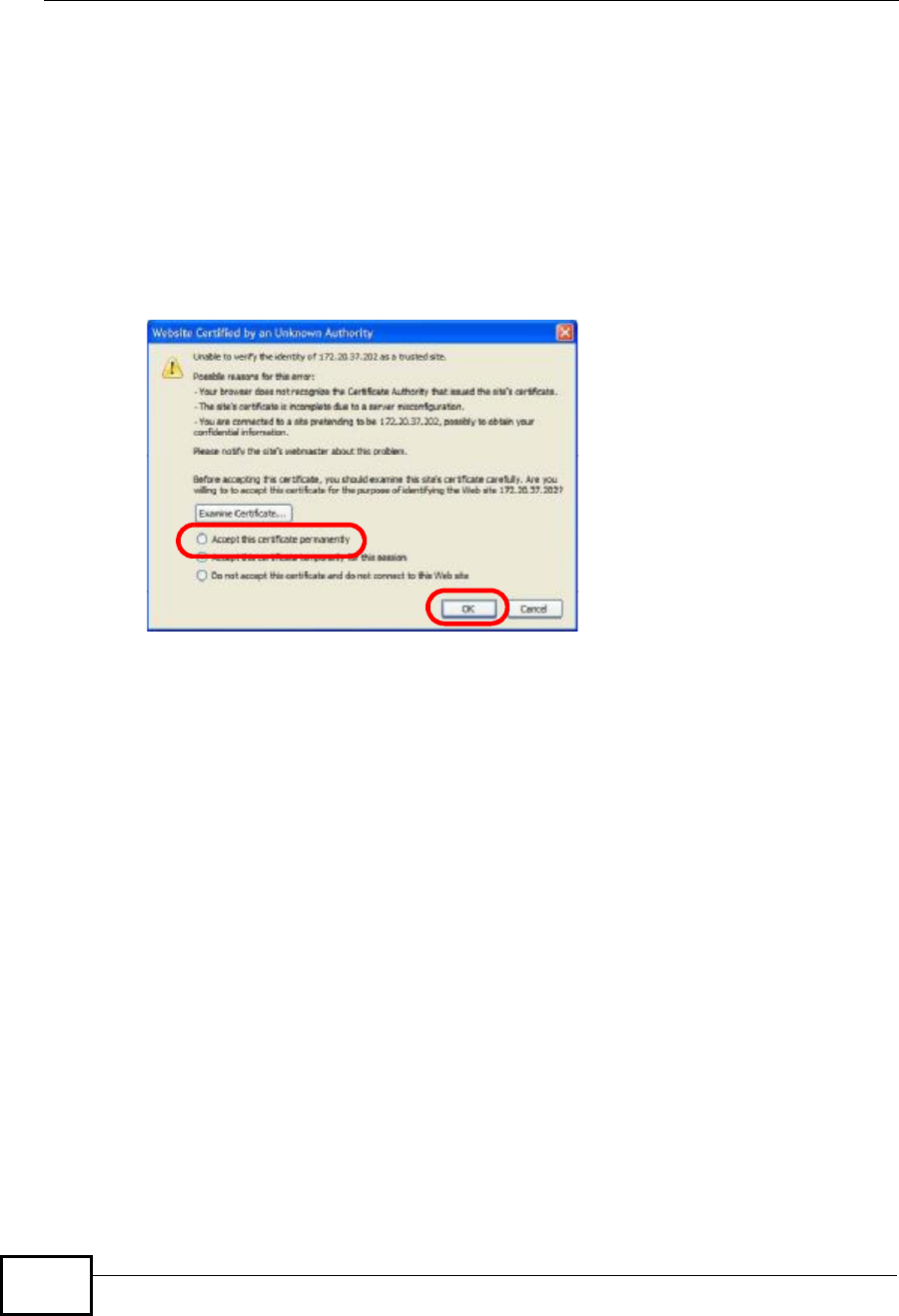
Appendix FImporting Certificates
User’s Guide
360
Firefox
The following example uses Mozilla Firefox 2 on Windows XP Professional;
however, the screens can also apply to Firefox 2 on all platforms.
1If your device’s web configurator is set to use SSL certification, then the first time
you browse to it you are presented with a certification error.
2Select Accept this certificate permanently and click OK.
Figure 207 Firefox 2: Website Certified by an Unknown Authority
Company Confidential
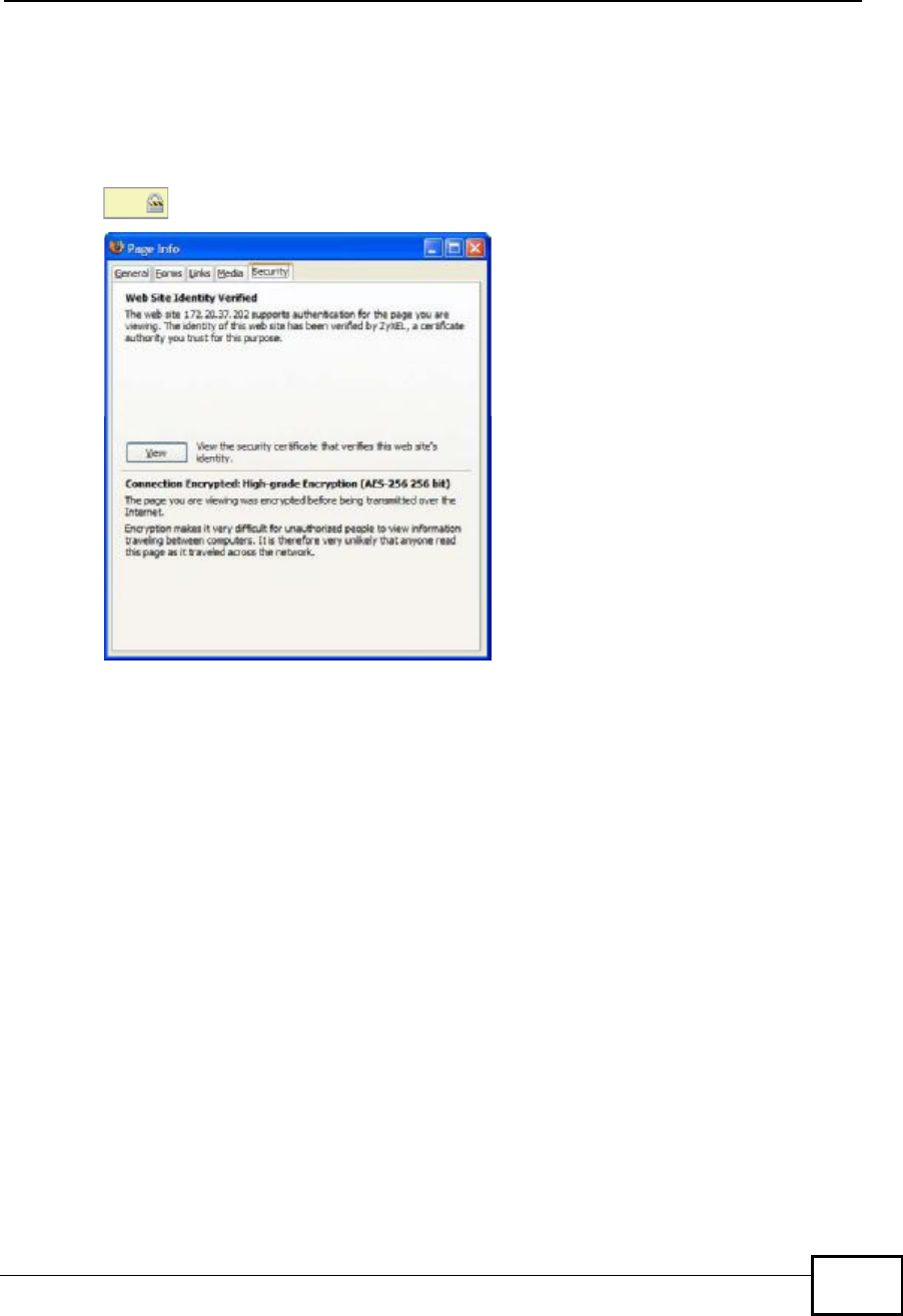
Appendix FImporting Certificates
User’s Guide 361
3The certificate is stored and you can now connect securely to the web
configurator. A sealed padlock appears in the address bar, which you can click to
open the Page Info > Security window to view the web page’s security
information.
Figure 208 Firefox 2: Page Info
Company Confidential
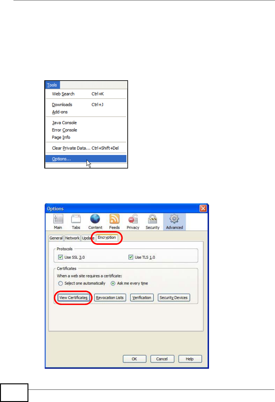
Appendix FImporting Certificates
User’s Guide
362
Installing a Stand-Alone Certificate File in Firefox
Rather than browsing to a ZyXEL web configurator and installing a public key
certificate when prompted, you can install a stand-alone certificate file if one has
been issued to you.
1Open Firefox and click TOOLS > Options.
Figure 209 Firefox 2: Tools Menu
2In the Options dialog box, click ADVANCED >Encryption > View Certificates.
Figure 210 Firefox 2: Options
Company Confidential
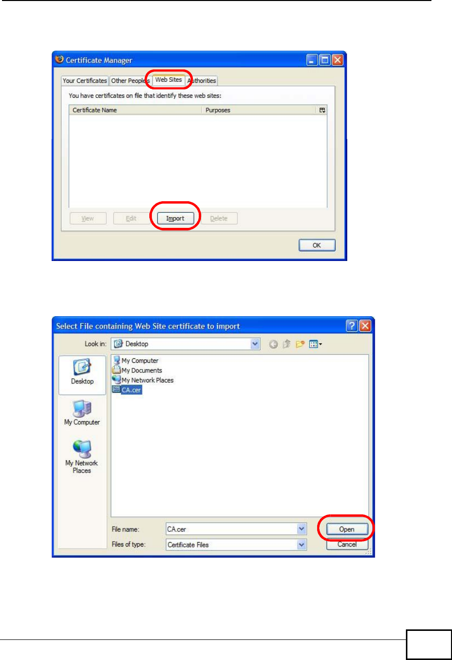
Appendix FImporting Certificates
User’s Guide 363
3In the Certificate Manager dialog box, click Web Sites > Import.
Figure 211 Firefox 2: Certificate Manager
4Use the Select File dialog box to locate the certificate and then click Open.
Figure 212 Firefox 2: Select File
5The next time you visit the web site, click the padlock in the address bar to open
the Page Info > Security window to see the web page’s security information.
Company Confidential
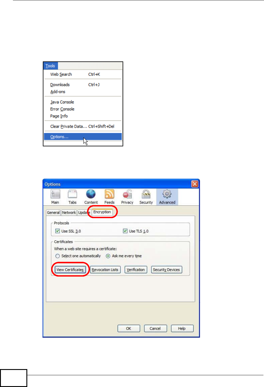
Appendix FImporting Certificates
User’s Guide
364
Removing a Certificate in Firefox
This section shows you how to remove a public key certificate in Firefox 2.
1Open Firefox and click TOOLS >Options.
Figure 213 Firefox 2: Tools Menu
2In the Options dialog box, click ADVANCED >Encryption > View Certificates.
Figure 214 Firefox 2: Options
Company Confidential
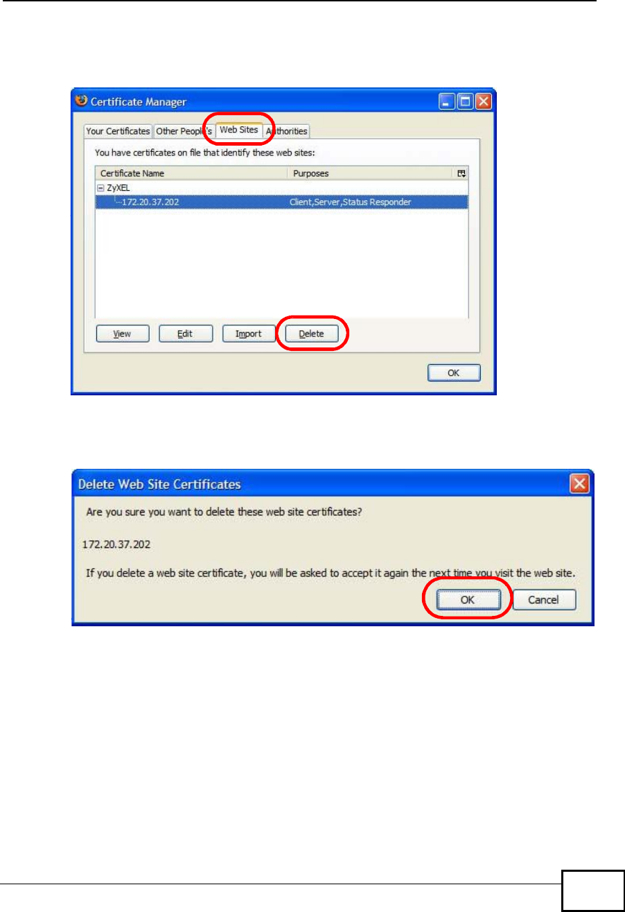
Appendix FImporting Certificates
User’s Guide 365
3In the Certificate Manager dialog box, select the Web Sites tab, select the
certificate that you want to remove, and then click Delete.
Figure 215 Firefox 2: Certificate Manager
4In the Delete Web Site Certificates dialog box, click OK.
Figure 216 Firefox 2: Delete Web Site Certificates
5The next time you go to the web site that issued the public key certificate you just
removed, a certification error appears.
Company Confidential
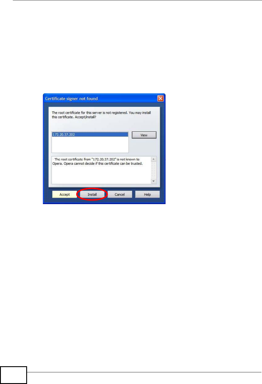
Appendix FImporting Certificates
User’s Guide
366
Opera
The following example uses Opera 9 on Windows XP Professional; however, the
screens can apply to Opera 9 on all platforms.
1If your device’s web configurator is set to use SSL certification, then the first time
you browse to it you are presented with a certification error.
2Click Install to accept the certificate.
Figure 217 Opera 9: Certificate signer not found
Company Confidential
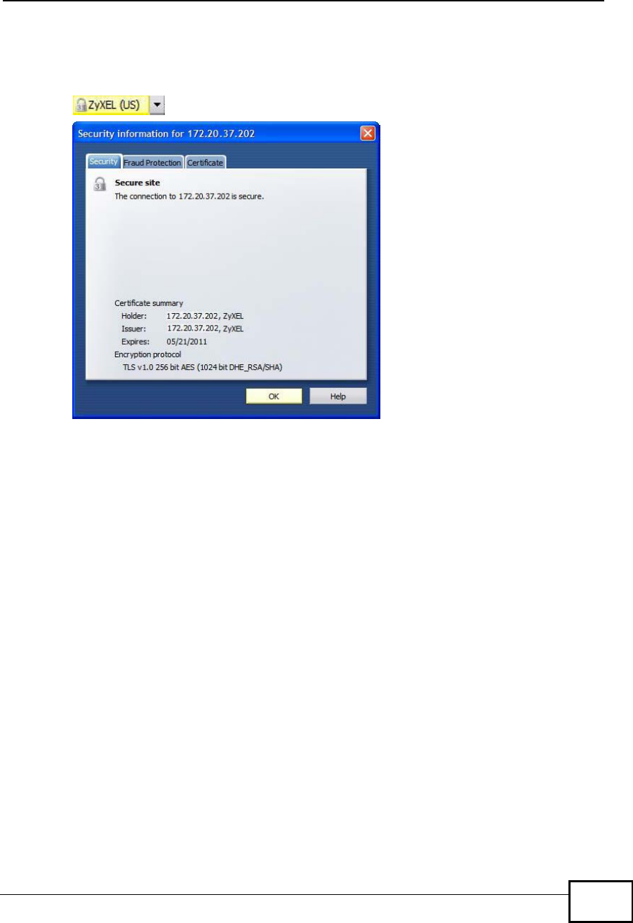
Appendix FImporting Certificates
User’s Guide 367
3The next time you visit the web site, click the padlock in the address bar to open
the Security information window to view the web page’s security details.
Figure 218 Opera 9: Security information
Company Confidential
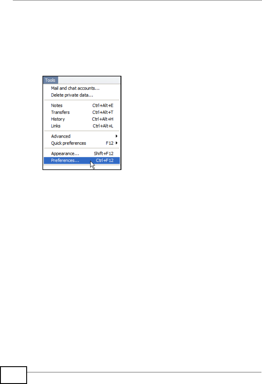
Appendix FImporting Certificates
User’s Guide
368
Installing a Stand-Alone Certificate File in Opera
Rather than browsing to a ZyXEL web configurator and installing a public key
certificate when prompted, you can install a stand-alone certificate file if one has
been issued to you.
1Open Opera and click TOOLS >Preferences.
Figure 219 Opera 9: Tools Menu
Company Confidential
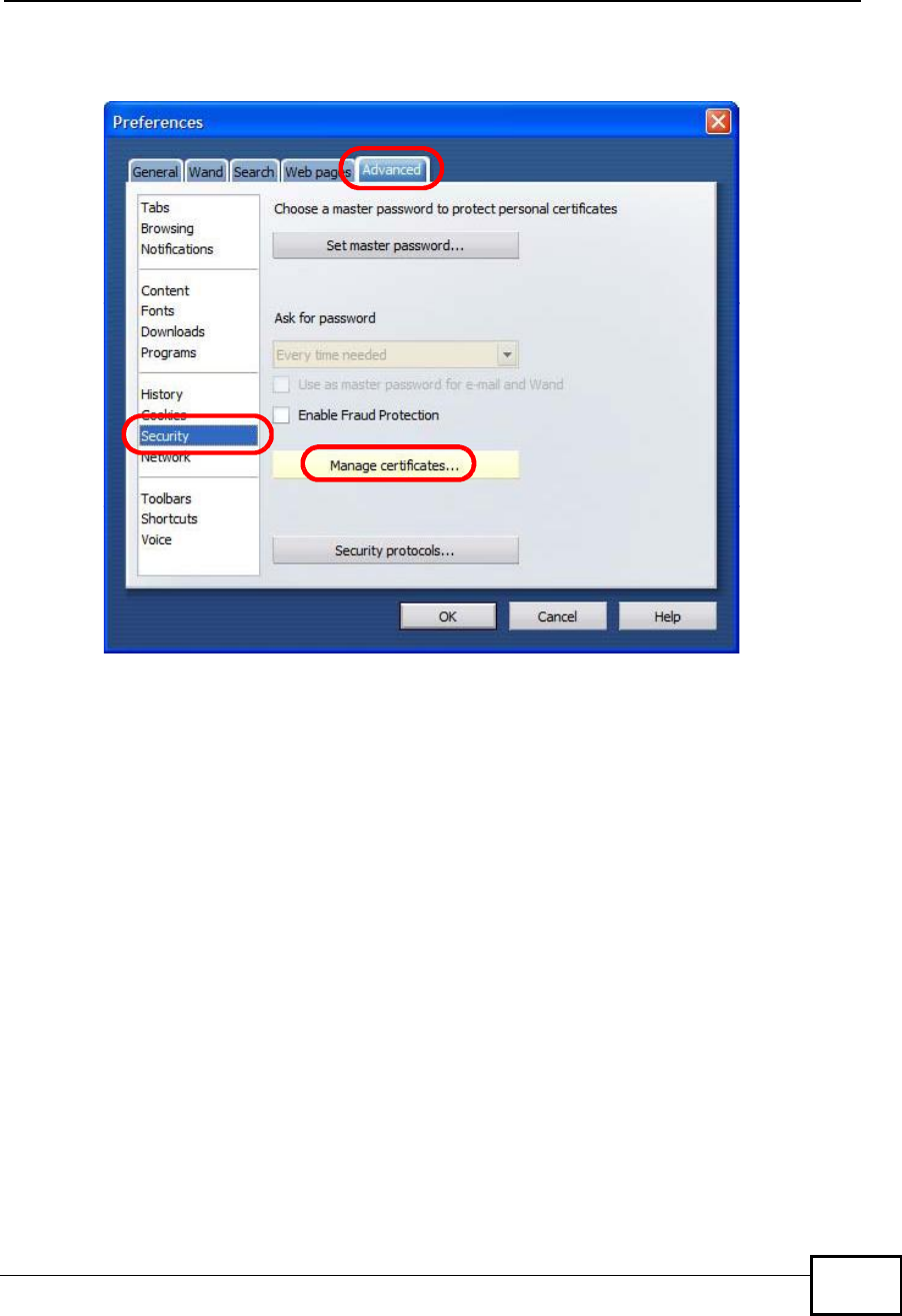
Appendix FImporting Certificates
User’s Guide 369
2In Preferences, click ADVANCED >Security > Manage certificates.
Figure 220 Opera 9: Preferences
Company Confidential
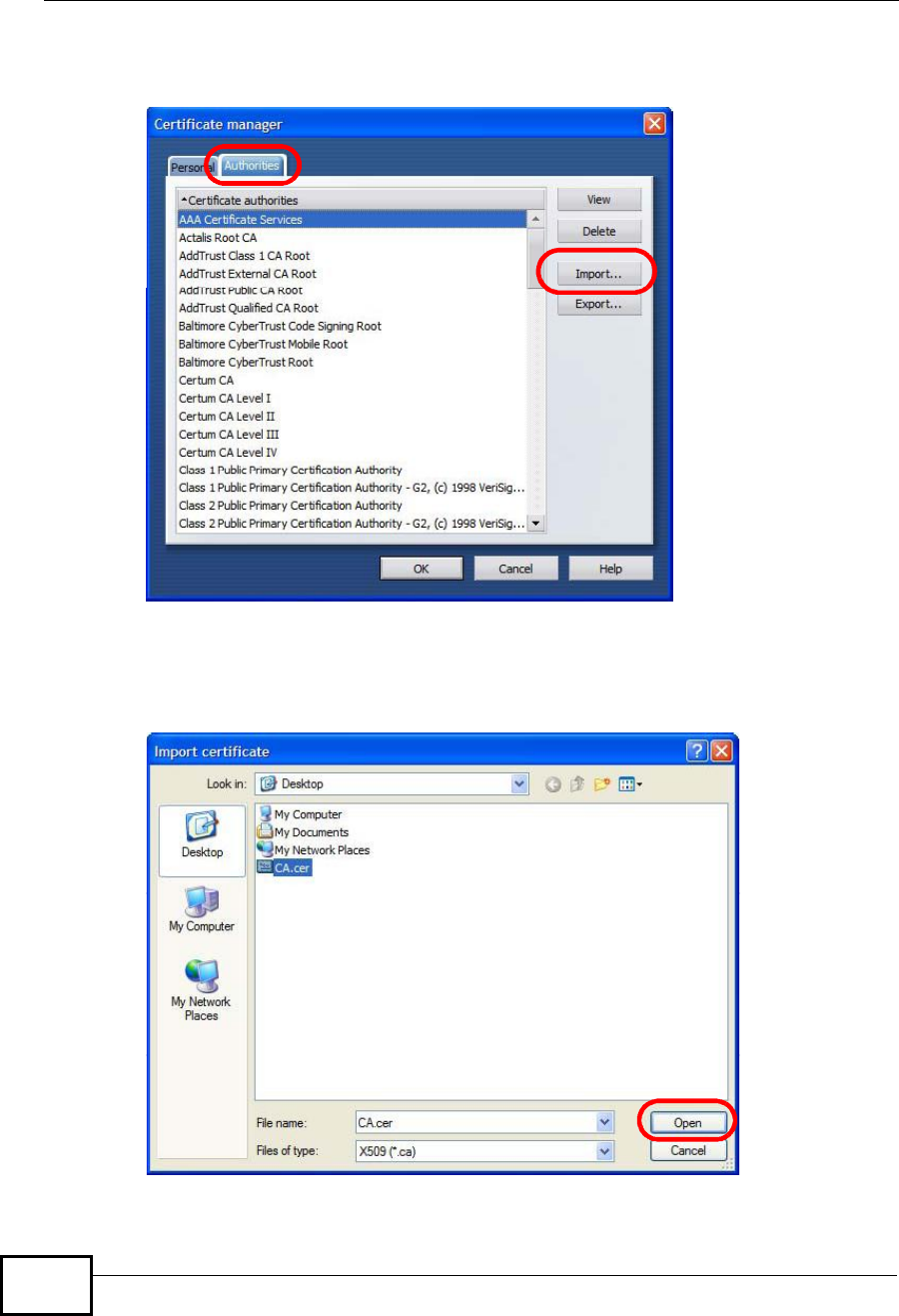
Appendix FImporting Certificates
User’s Guide
370
3In the Certificates Manager, click Authorities > Import.
Figure 221 Opera 9: Certificate manager
4Use the Import certificate dialog box to locate the certificate and then click
Open.
Figure 222 Opera 9: Import certificate
Company Confidential
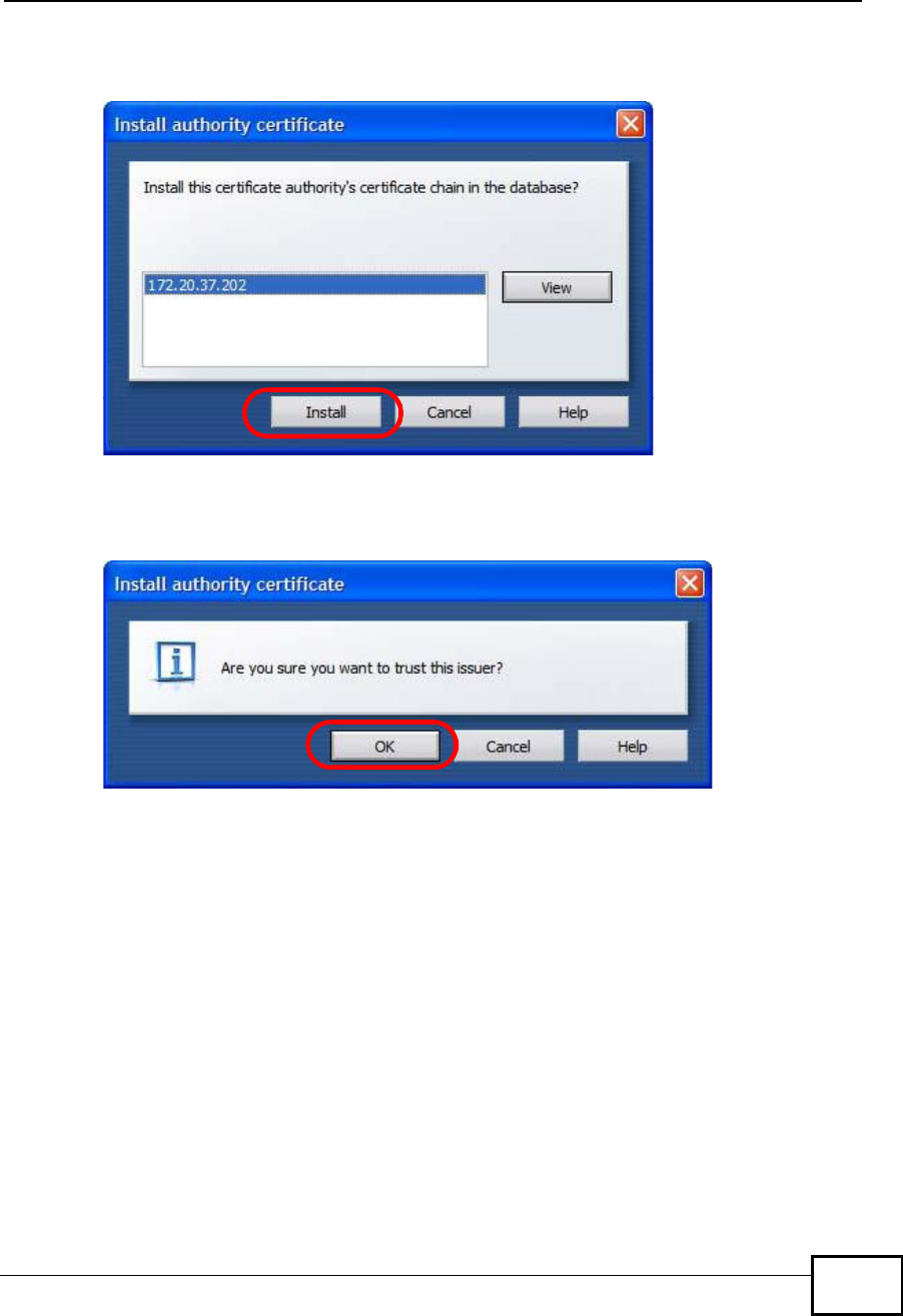
Appendix FImporting Certificates
User’s Guide 371
5In the Install authority certificate dialog box, click Install.
Figure 223 Opera 9: Install authority certificate
6Next, click OK.
Figure 224 Opera 9: Install authority certificate
7The next time you visit the web site, click the padlock in the address bar to open
the Security information window to view the web page’s security details.
Company Confidential
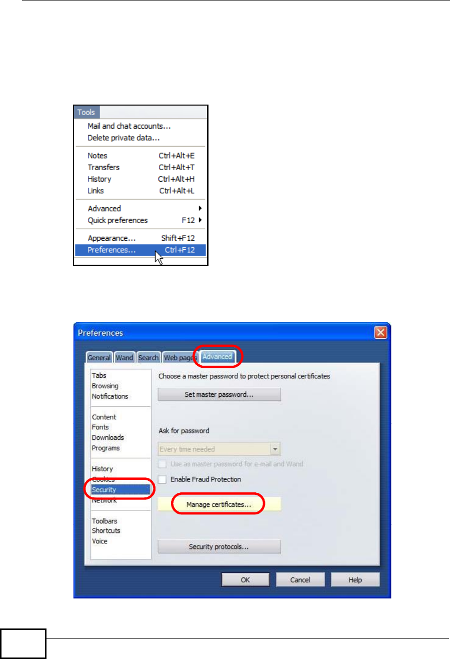
Appendix FImporting Certificates
User’s Guide
372
Removing a Certificate in Opera
This section shows you how to remove a public key certificate in Opera 9.
1Open Opera and click TOOLS >Preferences.
Figure 225 Opera 9: Tools Menu
2In Preferences,ADVANCED >Security > Manage certificates.
Figure 226 Opera 9: Preferences
Company Confidential
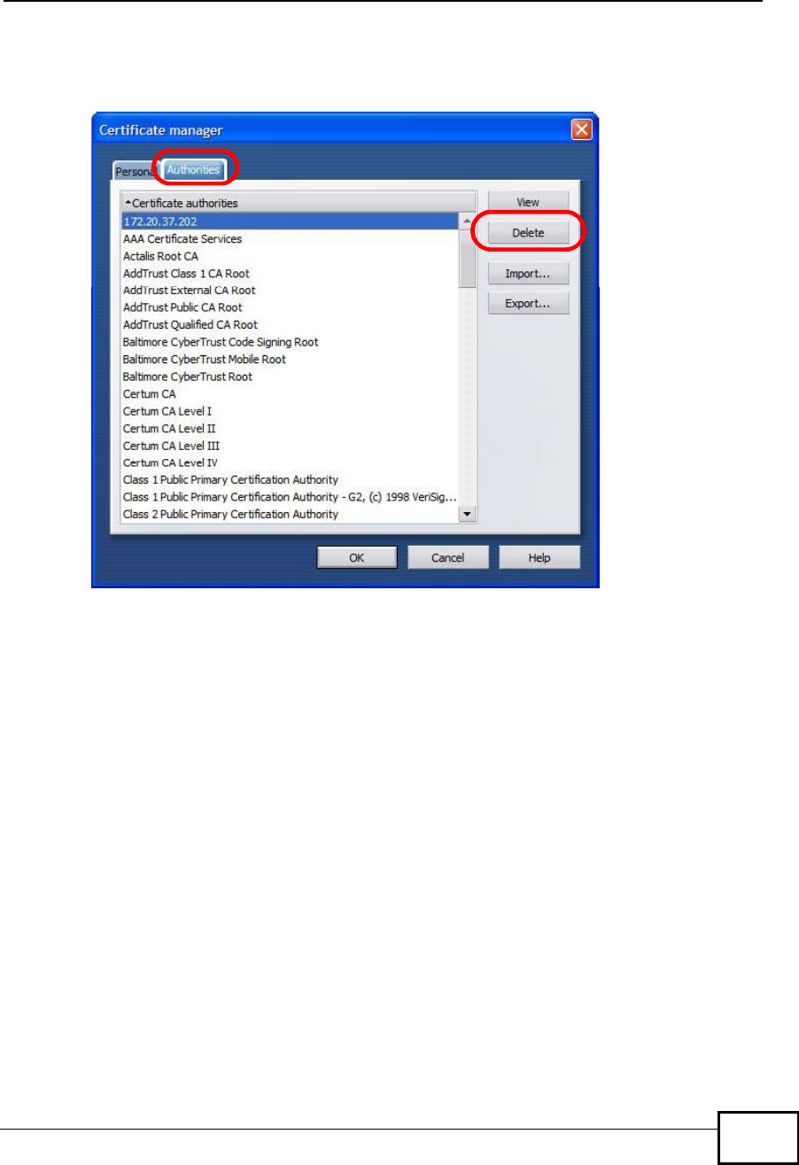
Appendix FImporting Certificates
User’s Guide 373
3In the Certificates manager, select the Authorities tab, select the certificate
that you want to remove, and then click Delete.
Figure 227 Opera 9: Certificate manager
4The next time you go to the web site that issued the public key certificate you just
removed, a certification error appears.
Note: There is no confirmation when you delete a certificate authority, so be
absolutely certain that you want to go through with it before clicking the button.
Company Confidential
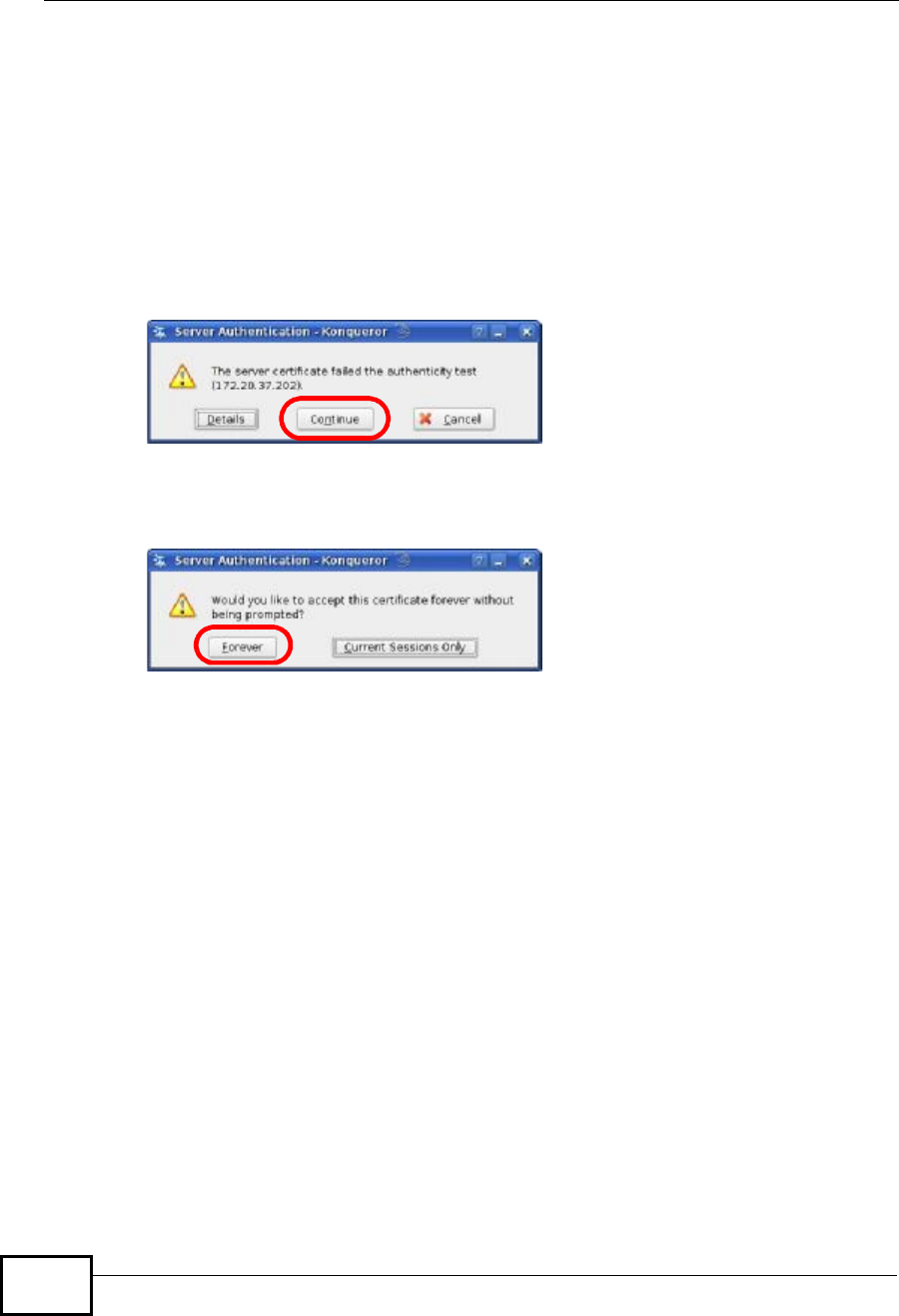
Appendix FImporting Certificates
User’s Guide
374
Konqueror
The following example uses Konqueror 3.5 on openSUSE 10.3, however the
screens apply to Konqueror 3.5 on all Linux KDE distributions.
1If your device’s web configurator is set to use SSL certification, then the first time
you browse to it you are presented with a certification error.
2Click Continue.
Figure 228 Konqueror 3.5: Server Authentication
3Click Forever when prompted to accept the certificate.
Figure 229 Konqueror 3.5: Server Authentication
Company Confidential
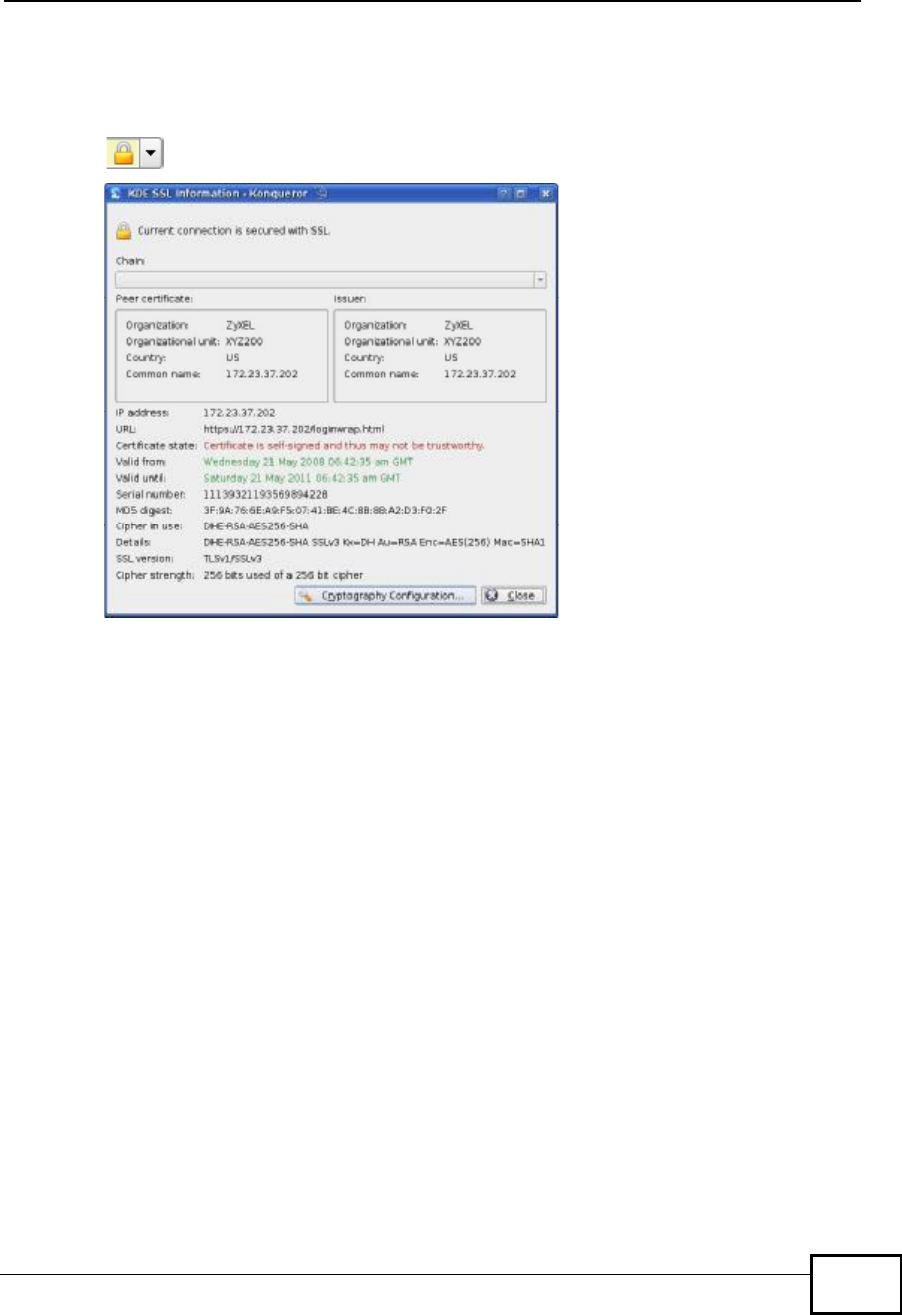
Appendix FImporting Certificates
User’s Guide 375
4Click the padlock in the address bar to open the KDE SSL Information window
and view the web page’s security details.
Figure 230 Konqueror 3.5: KDE SSL Information
Company Confidential
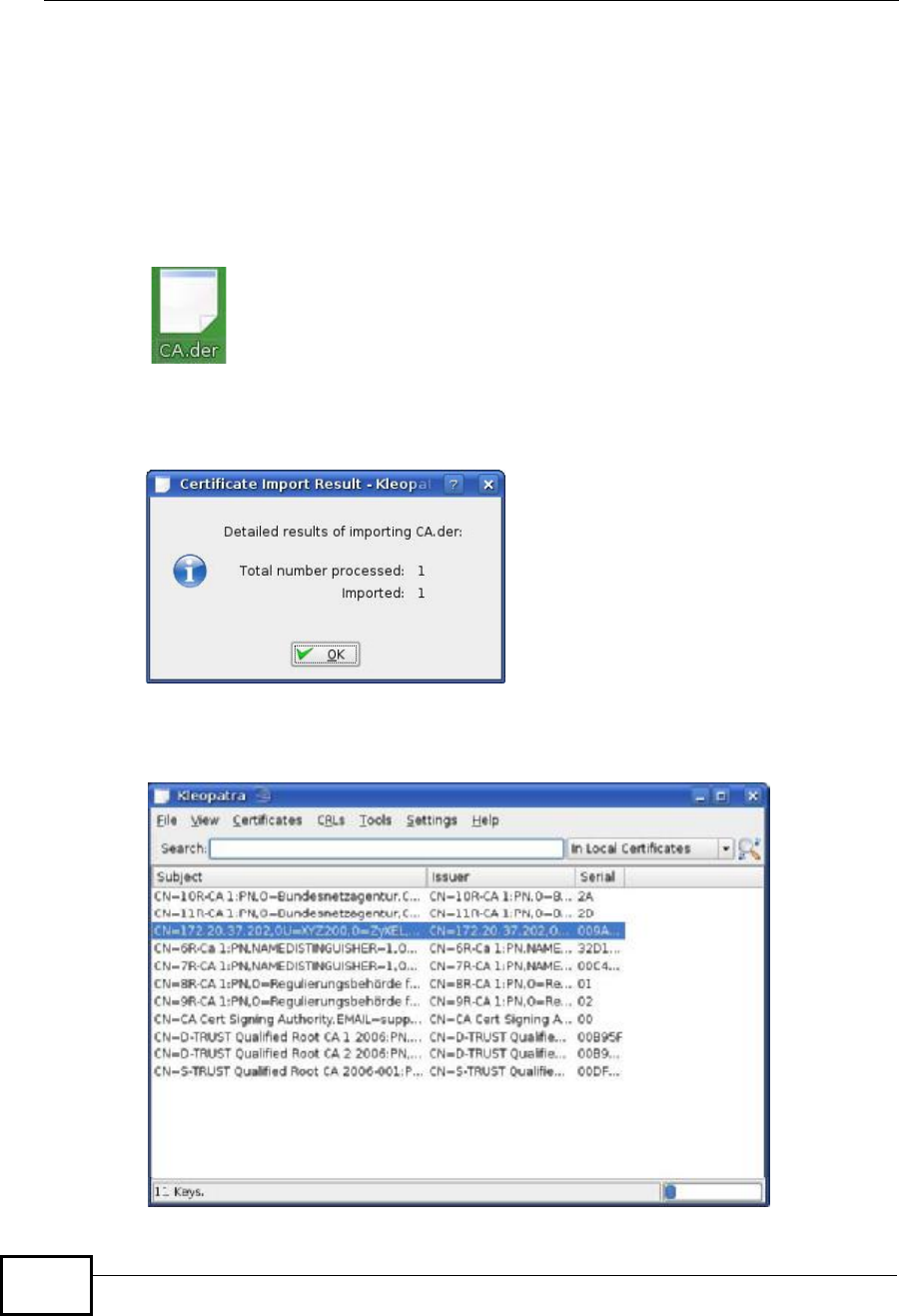
Appendix FImporting Certificates
User’s Guide
376
Installing a Stand-Alone Certificate File in Konqueror
Rather than browsing to a ZyXEL web configurator and installing a public key
certificate when prompted, you can install a stand-alone certificate file if one has
been issued to you.
1Double-click the public key certificate file.
Figure 231 Konqueror 3.5: Public Key Certificate File
2In the Certificate Import Result - Kleopatra dialog box, click OK.
Figure 232 Konqueror 3.5: Certificate Import Result
The public key certificate appears in the KDE certificate manager, Kleopatra.
Figure 233 Konqueror 3.5: Kleopatra
Company Confidential

Appendix FImporting Certificates
User’s Guide 377
3The next time you visit the web site, click the padlock in the address bar to open
the KDE SSL Information window to view the web page’s security details.
Company Confidential
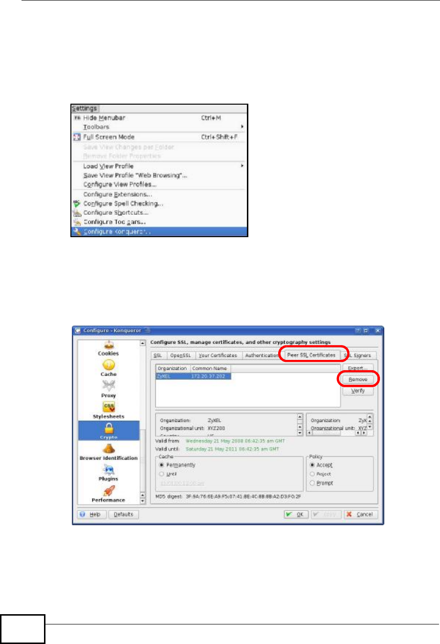
Appendix FImporting Certificates
User’s Guide
378
Removing a Certificate in Konqueror
This section shows you how to remove a public key certificate in Konqueror 3.5.
1Open Konqueror and click Settings > Configure Konqueror.
Figure 234 Konqueror 3.5: Settings Menu
2In the Configure dialog box, select Crypto.
3On the Peer SSL Certificates tab, select the certificate you want to delete and
then click Remove.
Figure 235 Konqueror 3.5: Configure
4The next time you go to the web site that issued the public key certificate you just
removed, a certification error appears.
Company Confidential

Appendix FImporting Certificates
User’s Guide 379
Note: There is no confirmation when you remove a certificate authority, so be
absolutely certain you want to go through with it before clicking the button.
Company Confidential

Appendix FImporting Certificates
User’s Guide
380
Company Confidential

User’s Guide 381
APPENDIX G
SIP Passthrough
Enabling/Disabling the SIP ALG
You can turn off the WiMAX Device SIP ALG to avoid retranslating the IP address
of an existing SIP device that is using STUN. If you want to use STUN with a SIP
client device (a SIP phone or IP phone for example) behind the WiMAX Device, use
the ip alg disable ALG_SIP command to turn off the SIP ALG.
Signaling Session Timeout
Most SIP clients have an “expire” mechanism indicating the lifetime of signaling
sessions. The SIP UA sends registration packets to the SIP server periodically and
keeps the session alive in the WiMAX Device.
If the SIP client does not have this mechanism and makes no call during the
WiMAX Device SIP timeout default (60 minutes), the WiMAX Device SIP ALG drops
any incoming calls after the timeout period. You can use the ip alg siptimeout
command to change the timeout value.
Audio Session Timeout
If no voice packets go through the SIP ALG before the timeout period default (5
minutes) expires, the SIP ALG does not drop the call but blocks all voice traffic
and deletes the audio session. You cannot hear anything and you will need to
make a new call to continue your conversation.
Company Confidential

Appendix GSIP Passthrough
User’s Guide
382
Company Confidential

User’s Guide 383
APPENDIX H
Common Services
The following table lists some commonly-used services and their associated
protocols and port numbers. For a comprehensive list of port numbers, ICMP type/
code numbers and services, visit the IANA (Internet Assigned Number Authority)
web site.
•Name: This is a short, descriptive name for the service. You can use this one or
create a different one, if you like.
•Protocol: This is the type of IP protocol used by the service. If this is TCP/
UDP, then the service uses the same port number with TCP and UDP. If this is
USER-DEFINED, the Port(s) is the IP protocol number, not the port number.
•Port(s): This value depends on the Protocol. Please refer to RFC 1700 for
further information about port numbers.
•If the Protocol is TCP,UDP, or TCP/UDP, this is the IP port number.
•If the Protocol is USER, this is the IP protocol number.
•Description: This is a brief explanation of the applications that use this service
or the situations in which this service is used.
Table 138 Commonly Used Services
NAME PROTOCOL PORT(S) DESCRIPTION
AH
(IPSEC_TUNNEL) User-Defined 51 The IPSEC AH (Authentication
Header) tunneling protocol uses this
service.
AIM/New-ICQ TCP 5190 AOL’s Internet Messenger service. It
is also used as a listening port by
ICQ.
AUTH TCP 113 Authentication protocol used by some
servers.
BGP TCP 179 Border Gateway Protocol.
BOOTP_CLIENT UDP 68 DHCP Client.
BOOTP_SERVER UDP 67 DHCP Server.
CU-SEEME TCP
UDP
7648
24032
A popular videoconferencing solution
from White Pines Software.
DNS TCP/UDP 53 Domain Name Server, a service that
matches web names (for example
www.zyxel.com) to IP numbers.
Company Confidential

Appendix HCommon Services
User’s Guide
384
ESP
(IPSEC_TUNNEL) User-Defined 50 The IPSEC ESP (Encapsulation
Security Protocol) tunneling protocol
uses this service.
FINGER TCP 79 Finger is a UNIX or Internet related
command that can be used to find out
if a user is logged on.
FTP TCP
TCP
20
21
File Transfer Program, a program to
enable fast transfer of files, including
large files that may not be possible by
e-mail.
H.323 TCP 1720 NetMeeting uses this protocol.
HTTP TCP 80 Hyper Text Transfer Protocol - a
client/server protocol for the world
wide web.
HTTPS TCP 443 HTTPS is a secured http session often
used in e-commerce.
ICMP User-Defined 1 Internet Control Message Protocol is
often used for diagnostic or routing
purposes.
ICQ UDP 4000 This is a popular Internet chat
program.
IGMP
(MULTICAST) User-Defined 2 Internet Group Management Protocol
is used when sending packets to a
specific group of hosts.
IKE UDP 500 The Internet Key Exchange algorithm
is used for key distribution and
management.
IRC TCP/UDP 6667 This is another popular Internet chat
program.
MSN Messenger TCP 1863 Microsoft Networks’ messenger
service uses this protocol.
NEW-ICQ TCP 5190 An Internet chat program.
NEWS TCP 144 A protocol for news groups.
NFS UDP 2049 Network File System - NFS is a client/
server distributed file service that
provides transparent file sharing for
network environments.
NNTP TCP 119 Network News Transport Protocol is
the delivery mechanism for the
USENET newsgroup service.
PING User-Defined 1 Packet INternet Groper is a protocol
that sends out ICMP echo requests to
test whether or not a remote host is
reachable.
POP3 TCP 110 Post Office Protocol version 3 lets a
client computer get e-mail from a
POP3 server through a temporary
connection (TCP/IP or other).
Table 138 Commonly Used Services (continued)
NAME PROTOCOL PORT(S) DESCRIPTION
Company Confidential

Appendix HCommon Services
User’s Guide 385
PPTP TCP 1723 Point-to-Point Tunneling Protocol
enables secure transfer of data over
public networks. This is the control
channel.
PPTP_TUNNEL
(GRE) User-Defined 47 PPTP (Point-to-Point Tunneling
Protocol) enables secure transfer of
data over public networks. This is the
data channel.
RCMD TCP 512 Remote Command Service.
REAL_AUDIO TCP 7070 A streaming audio service that
enables real time sound over the
web.
REXEC TCP 514 Remote Execution Daemon.
RLOGIN TCP 513 Remote Login.
RTELNET TCP 107 Remote Telnet.
RTSP TCP/UDP 554 The Real Time Streaming (media
control) Protocol (RTSP) is a remote
control for multimedia on the
Internet.
SFTP TCP 115 Simple File Transfer Protocol.
SMTP TCP 25 Simple Mail Transfer Protocol is the
message-exchange standard for the
Internet. SMTP enables you to move
messages from one e-mail server to
another.
SNMP TCP/UDP 161 Simple Network Management
Program.
SNMP-TRAPS TCP/UDP 162 Traps for use with the SNMP
(RFC:1215).
SQL-NET TCP 1521 Structured Query Language is an
interface to access data on many
different types of database systems,
including mainframes, midrange
systems, UNIX systems and network
servers.
SSH TCP/UDP 22 Secure Shell Remote Login Program.
STRM WORKS UDP 1558 Stream Works Protocol.
SYSLOG UDP 514 Syslog allows you to send system logs
to a UNIX server.
TACACS UDP 49 Login Host Protocol used for
(Terminal Access Controller Access
Control System).
TELNET TCP 23 Telnet is the login and terminal
emulation protocol common on the
Internet and in UNIX environments. It
operates over TCP/IP networks. Its
primary function is to allow users to
log into remote host systems.
Table 138 Commonly Used Services (continued)
NAME PROTOCOL PORT(S) DESCRIPTION
Company Confidential

Appendix HCommon Services
User’s Guide
386
TFTP UDP 69 Trivial File Transfer Protocol is an
Internet file transfer protocol similar
to FTP, but uses the UDP (User
Datagram Protocol) rather than TCP
(Transmission Control Protocol).
VDOLIVE TCP 7000 Another videoconferencing solution.
Table 138 Commonly Used Services (continued)
NAME PROTOCOL PORT(S) DESCRIPTION
Company Confidential

User’s Guide 387
APPENDIX I
Legal Information
Copyright
Copyright © 2009 by ZyXEL Communications Corporation.
The contents of this publication may not be reproduced in any part or as a whole,
transcribed, stored in a retrieval system, translated into any language, or
transmitted in any form or by any means, electronic, mechanical, magnetic,
optical, chemical, photocopying, manual, or otherwise, without the prior written
permission of ZyXEL Communications Corporation.
Published by ZyXEL Communications Corporation. All rights reserved.
Disclaimers
ZyXEL does not assume any liability arising out of the application or use of any
products, or software described herein. Neither does it convey any license under
its patent rights nor the patent rights of others. ZyXEL further reserves the right
to make changes in any products described herein without notice. This publication
is subject to change without notice.
Your use of the WiMAX Device is subject to the terms and conditions of any related
service providers.
Do not use the WiMAX Device for illegal purposes. Illegal downloading or sharing
of files can result in severe civil and criminal penalties. You are subject to the
restrictions of copyright laws and any other applicable laws, and will bear the
consequences of any infringements thereof. ZyXEL bears NO responsibility or
liability for your use of the download service feature.
Trademarks
Trademarks mentioned in this publication are used for identification purposes only
and may be properties of their respective owners.
Company Confidential

Appendix ILegal Information
User’s Guide
388
Certifications
Federal Communications Commission (FCC) Interference Statement
The device complies with Part 15 of FCC rules. Operation is subject to the
following two conditions:
•This device may not cause harmful interference.
•This device must accept any interference received, including interference that
may cause undesired operations.
This device has been tested and found to comply with the limits for a Class B
digital device pursuant to Part 15 of the FCC Rules. These limits are designed to
provide reasonable protection against harmful interference in a residential
installation. This device generates, uses, and can radiate radio frequency energy,
and if not installed and used in accordance with the instructions, may cause
harmful interference to radio communications. However, there is no guarantee
that interference will not occur in a particular installation.
If this device does cause harmful interference to radio/television reception, which
can be determined by turning the device off and on, the user is encouraged to try
to correct the interference by one or more of the following measures:
1Reorient or relocate the receiving antenna.
2Increase the separation between the equipment and the receiver.
3Connect the equipment into an outlet on a circuit different from that to which the
receiver is connected.
4Consult the dealer or an experienced radio/TV technician for help.
FCC Radiation Exposure Statement
•This transmitter must not be co-located or operating in conjunction
with any other antenna or transmitter.
•To comply with FCC RF exposure compliance requirements, a separation
distance ofatleast23cm mustbemaintainedbetweenthe antenna ofthis
device and all persons.
Company Confidential

Appendix ILegal Information
User’s Guide 389
Notices
Changes or modifications not expressly approved by the party responsible for
compliance could void the user's authority to operate the equipment.
This Class B digital apparatus complies with Canadian ICES-003.
Cet appareil numérique de la classe B est conforme à la norme NMB-003 du
Canada.
Viewing Certifications
1Go to http://www.zyxel.com.
2Select your product on the ZyXEL home page to go to that product's page.
3Select the certification you wish to view from this page.
ZyXEL Limited Warranty
ZyXEL warrants to the original end user (purchaser) that this product is free from
any defects in materials or workmanship for a period of up to two years from the
date of purchase. During the warranty period, and upon proof of purchase, should
the product have indications of failure due to faulty workmanship and/or
materials, ZyXEL will, at its discretion, repair or replace the defective products or
components without charge for either parts or labor, and to whatever extent it
shall deem necessary to restore the product or components to proper operating
condition. Any replacement will consist of a new or re-manufactured functionally
equivalent product of equal or higher value, and will be solely at the discretion of
ZyXEL. This warranty shall not apply if the product has been modified, misused,
tampered with, damaged by an act of God, or subjected to abnormal working
conditions.
Note
Repair or replacement, as provided under this warranty, is the exclusive remedy
of the purchaser. This warranty is in lieu of all other warranties, express or
Company Confidential

Appendix ILegal Information
User’s Guide
390
implied, including any implied warranty of merchantability or fitness for a
particular use or purpose. ZyXEL shall in no event be held liable for indirect or
consequential damages of any kind to the purchaser.
To obtain the services of this warranty, contact your vendor. You may also refer to
the warranty policy for the region in which you bought the device at http://
www.zyxel.com/web/support_warranty_info.php.
Registration
Register your product online to receive e-mail notices of firmware upgrades and
information at www.zyxel.com.
Company Confidential

User’s Guide 391
APPENDIX J
Customer Support
In the event of problems that cannot be solved by using this manual, you should
contact your vendor. If you cannot contact your vendor, then contact a ZyXEL
office for the region in which you bought the device. Regional offices are listed
below (see also http://www.zyxel.com/web/contact_us.php). Please have the
following information ready when you contact an office.
Required Information
•Product model and serial number.
•Warranty Information.
•Date that you received your device.
•Brief description of the problem and the steps you took to solve it.
“+” is the (prefix) number you dial to make an international telephone call.
Corporate Headquarters (Worldwide)
•Support E-mail: support@zyxel.com.tw
•Sales E-mail: sales@zyxel.com.tw
•Telephone: +886-3-578-3942
•Fax: +886-3-578-2439
•Web: www.zyxel.com
•Regular Mail: ZyXEL Communications Corp., 6 Innovation Road II, Science
Park, Hsinchu 300, Taiwan
China - ZyXEL Communications (Beijing) Corp.
•Support E-mail: cso.zycn@zyxel.cn
•Sales E-mail: sales@zyxel.cn
•Telephone: +86-010-82800646
•Fax: +86-010-82800587
•Address: 902, Unit B, Horizon Building, No.6, Zhichun Str, Haidian District,
Beijing
•Web: http://www.zyxel.cn
Company Confidential

Appendix JCustomer Support
User’s Guide
392
China - ZyXEL Communications (Shanghai) Corp.
•Support E-mail: cso.zycn@zyxel.cn
•Sales E-mail: sales@zyxel.cn
•Telephone: +86-021-61199055
•Fax: +86-021-52069033
•Address: 1005F, ShengGao International Tower, No.137 XianXia Rd., Shanghai
•Web: http://www.zyxel.cn
Costa Rica
•Support E-mail: soporte@zyxel.co.cr
•Sales E-mail: sales@zyxel.co.cr
•Telephone: +506-2017878
•Fax: +506-2015098
•Web: www.zyxel.co.cr
•Regular Mail: ZyXEL Costa Rica, Plaza Roble Escazú, Etapa El Patio, Tercer Piso,
San José, Costa Rica
Czech Republic
•E-mail: info@cz.zyxel.com
•Telephone: +420-241-091-350
•Fax: +420-241-091-359
•Web: www.zyxel.cz
•Regular Mail: ZyXEL Communications, Czech s.r.o., Modranská 621, 143 01
Praha 4 - Modrany, Ceská Republika
Denmark
•Support E-mail: support@zyxel.dk
•Sales E-mail: sales@zyxel.dk
•Telephone: +45-39-55-07-00
•Fax: +45-39-55-07-07
•Web: www.zyxel.dk
•Regular Mail: ZyXEL Communications A/S, Columbusvej, 2860 Soeborg,
Denmark
Finland
•Support E-mail: support@zyxel.fi
•Sales E-mail: sales@zyxel.fi
•Telephone: +358-9-4780-8411
Company Confidential

Appendix JCustomer Support
User’s Guide 393
•Fax: +358-9-4780-8448
•Web: www.zyxel.fi
•Regular Mail: ZyXEL Communications Oy, Malminkaari 10, 00700 Helsinki,
Finland
France
•E-mail: info@zyxel.fr
•Telephone: +33-4-72-52-97-97
•Fax: +33-4-72-52-19-20
•Web: www.zyxel.fr
•Regular Mail: ZyXEL France, 1 rue des Vergers, Bat. 1 / C, 69760 Limonest,
France
Germany
•Support E-mail: support@zyxel.de
•Sales E-mail: sales@zyxel.de
•Telephone: +49-2405-6909-69
•Fax: +49-2405-6909-99
•Web: www.zyxel.de
•Regular Mail: ZyXEL Deutschland GmbH., Adenauerstr. 20/A2 D-52146,
Wuerselen, Germany
Hungary
•Support E-mail: support@zyxel.hu
•Sales E-mail: info@zyxel.hu
•Telephone: +36-1-3361649
•Fax: +36-1-3259100
•Web: www.zyxel.hu
•Regular Mail: ZyXEL Hungary, 48, Zoldlomb Str., H-1025, Budapest, Hungary
India
•Support E-mail: support@zyxel.in
•Sales E-mail: sales@zyxel.in
•Telephone: +91-11-30888144 to +91-11-30888153
•Fax: +91-11-30888149, +91-11-26810715
•Web: http://www.zyxel.in
•Regular Mail: India - ZyXEL Technology India Pvt Ltd., II-Floor, F2/9 Okhla
Phase -1, New Delhi 110020, India
Company Confidential

Appendix JCustomer Support
User’s Guide
394
Japan
•Support E-mail: support@zyxel.co.jp
•Sales E-mail: zyp@zyxel.co.jp
•Telephone: +81-3-6847-3700
•Fax: +81-3-6847-3705
•Web: www.zyxel.co.jp
•Regular Mail: ZyXEL Japan, 3F, Office T&U, 1-10-10 Higashi-Gotanda,
Shinagawa-ku, Tokyo 141-0022, Japan
Kazakhstan
•Support: http://zyxel.kz/support
•Sales E-mail: sales@zyxel.kz
•Telephone: +7-3272-590-698
•Fax: +7-3272-590-689
•Web: www.zyxel.kz
•Regular Mail: ZyXEL Kazakhstan, 43 Dostyk Ave., Office 414, Dostyk Business
Centre, 050010 Almaty, Republic of Kazakhstan
Malaysia
•Support E-mail: support@zyxel.com.my
•Sales E-mail: sales@zyxel.com.my
•Telephone: +603-8076-9933
•Fax: +603-8076-9833
•Web: http://www.zyxel.com.my
•Regular Mail: ZyXEL Malaysia Sdn Bhd., 1-02 & 1-03, Jalan Kenari 17F, Bandar
Puchong Jaya, 47100 Puchong, Selangor Darul Ehsan, Malaysia
North America
•Support E-mail: support@zyxel.com
•Support Telephone: +1-800-978-7222
•Sales E-mail: sales@zyxel.com
•Sales Telephone: +1-714-632-0882
•Fax: +1-714-632-0858
•Web: www.zyxel.com
•Regular Mail: ZyXEL Communications Inc., 1130 N. Miller St., Anaheim, CA
92806-2001, U.S.A.
Norway
•Support E-mail: support@zyxel.no
Company Confidential

Appendix JCustomer Support
User’s Guide 395
•Sales E-mail: sales@zyxel.no
•Telephone: +47-22-80-61-80
•Fax: +47-22-80-61-81
•Web: www.zyxel.no
•Regular Mail: ZyXEL Communications A/S, Nils Hansens vei 13, 0667 Oslo,
Norway
Poland
•E-mail: info@pl.zyxel.com
•Telephone: +48-22-333 8250
•Fax: +48-22-333 8251
•Web: www.pl.zyxel.com
•Regular Mail: ZyXEL Communications, ul. Okrzei 1A, 03-715 Warszawa, Poland
Russia
•Support: http://zyxel.ru/support
•Sales E-mail: sales@zyxel.ru
•Telephone: +7-095-542-89-29
•Fax: +7-095-542-89-25
•Web: www.zyxel.ru
•Regular Mail: ZyXEL Russia, Ostrovityanova 37a Str., Moscow 117279, Russia
Singapore
•Support E-mail: support@zyxel.com.sg
•Sales E-mail: sales@zyxel.com.sg
•Telephone: +65-6899-6678
•Fax: +65-6899-8887
•Web: http://www.zyxel.com.sg
•Regular Mail: ZyXEL Singapore Pte Ltd., No. 2 International Business Park, The
Strategy #03-28, Singapore 609930
Spain
•Support E-mail: support@zyxel.es
•Sales E-mail: sales@zyxel.es
•Telephone: +34-902-195-420
•Fax: +34-913-005-345
•Web: www.zyxel.es
•Regular Mail: ZyXEL Communications, Arte, 21 5ª planta, 28033 Madrid, Spain
Company Confidential

Appendix JCustomer Support
User’s Guide
396
Sweden
•Support E-mail: support@zyxel.se
•Sales E-mail: sales@zyxel.se
•Telephone: +46-31-744-7700
•Fax: +46-31-744-7701
•Web: www.zyxel.se
•Regular Mail: ZyXEL Communications A/S, Sjöporten 4, 41764 Göteborg,
Sweden
Taiwan
•Support E-mail: support@zyxel.com.tw
•Sales E-mail: sales@zyxel.com.tw
•Telephone: +886-2-27399889
•Fax: +886-2-27353220
•Web: http://www.zyxel.com.tw
•Address: Room B, 21F., No.333, Sec. 2, Dunhua S. Rd., Da-an District, Taipei
Thailand
•Support E-mail: support@zyxel.co.th
•Sales E-mail: sales@zyxel.co.th
•Telephone: +662-831-5315
•Fax: +662-831-5395
•Web: http://www.zyxel.co.th
•Regular Mail: ZyXEL Thailand Co., Ltd., 1/1 Moo 2, Ratchaphruk Road,
Bangrak-Noi, Muang, Nonthaburi 11000, Thailand.
Turkey
•Support E-mail: cso@zyxel.com.tr
•Telephone: +90 212 222 55 22
•Fax: +90-212-220-2526
•Web: http:www.zyxel.com.tr
•Address: Kaptanpasa Mahallesi Piyalepasa Bulvari Ortadogu Plaza N:14/13 K:6
Okmeydani/Sisli Istanbul/Turkey
Ukraine
•Support E-mail: support@ua.zyxel.com
•Sales E-mail: sales@ua.zyxel.com
•Telephone: +380-44-247-69-78
Company Confidential

Appendix JCustomer Support
User’s Guide 397
•Fax: +380-44-494-49-32
•Web: www.ua.zyxel.com
•Regular Mail: ZyXEL Ukraine, 13, Pimonenko Str., Kiev 04050, Ukraine
United Kingdom
•Support E-mail: support@zyxel.co.uk
•Sales E-mail: sales@zyxel.co.uk
•Telephone: +44-1344-303044, 0845 122 0301 (UK only)
•Fax: +44-1344-303034
•Web: www.zyxel.co.uk
•Regular Mail: ZyXEL Communications UK Ltd., 11 The Courtyard, Eastern Road,
Bracknell, Berkshire RG12 2XB, United Kingdom (UK)
Company Confidential

Appendix JCustomer Support
User’s Guide
398
Company Confidential

Index
User’s Guide 399
Index
A
AAA 91
AbS 152
accounting server
see AAA
ACK message 159
activity 91
Advanced Encryption Standard
see AES
See AES.
AES 281,321
ALG 132
alternative subnet mask notation 340
analysis-by-synthesis 152
antenna
directional 326
gain 325
omni-directional 326
AP (access point) 313
Application Layer Gateway
see ALG
authentication 55,91,94,279
inner 282
key
server 91
types 282
authorization 279
request and reply 281
server 91
auto-discovery
UPnP 246
B
base station
see BS
Basic Service Set, See BSS 311
BS 89–90
links 90
BSS 311
BYE request 160
C
CA 183,199,319
and certificates 199
call
Europe type service mode 171
hold 171–173
service mode 171–173
transfer 172–173
waiting 171–173
CBC-MAC 281
CCMP 279,281
cell 89
Certificate Authority
See CA.
Certificate Management Protocol (CMP) 188
Certificate Revocation List (CRL) 199
certificates 183,279
advantages 199
and CA 199
certification path 190,196,199
expired 199
factory-default 200
file formats 200
fingerprints 191,197
importing 185
not used for encryption 199
revoked 199
self-signed 187
serial number 190,196
storage space 184
thumbprint algorithms 201
thumbprints 201
used for authentication 199
verification 281
verifying fingerprints 201
certification
Company Confidential

Index
User’s Guide
400
authority, see CA
notices 389
requests 183,187,188
viewing 389
chaining 281
chaining message authentication
see CCMP
channel 313
interference 313
circuit-switched telephone networks 147
Class of Service (CoS) 162
client-server
protocol 160
SIP 160
CMAC
see MAC
codec 152
comfort noise 165
contact information 391
copyright 387
CoS 162
counter mode
see CCMP
coverage area 89
cryptography 279
CTS (Clear to Send) 314
customer support 391
D
data 279–281
decryption 279
encryption 279
flow 281
device name 245
DHCP 76,136,138
client 136
server 76
diameter 91
Differentiated Services
see DiffServ
DiffServ 162
DiffServ Code Point (DSCP) 162
marking rule 163
digital ID 279
DL frequency 98,99
domain name 136
download frequency
see DL frequency
DS field 163
DSCP
see DiffServ
dynamic DNS 138
Dynamic Host Configuration Protocol
see DHCP
dynamic WEP key exchange 320
E
EAP 91
EAP Authentication 318
echo cancellation 165
encryption 279–281,321
traffic 281
ESS 312
Ethernet
encapsulation 126
Europe type call service mode 171
Extended Service Set, See ESS 312
Extensible Authorization Protocol
see EAP
F
FCC interference statement 388
firewall 203,208,209
flash key 170
flashing 170
fragmentation threshold 315
frequency
band 99
ranges 98,99
scanning 99
FTP 138,218
restrictions 218
Company Confidential

Index
User’s Guide 401
G
G.168 165
G.711 152
G.729 152
H
hidden node 313
hybrid waveform codec 152
I
IANA 346
IBSS 311
identity 91,279
idle timeout 218
IEEE 802.11g 315
IEEE 802.16 89,279
IEEE 802.16e 89
IEEE 802.1Q VLAN 158
IGD 1.0 244
Independent Basic Service Set
See IBSS 311
initialization vector (IV) 321
inner authentication 282
Internet
access 91
gateway device 244
Internet Assigned Numbers Authority
see IANA 346
Internet Telephony Service Provider
see ITSP
interoperability 89
IP-PBX 147
ITSP 147
ITU-T 165
K
key 55,94,279
request and reply 281
L
listening port 155
M
MAC 281
MAN 89
Management Information Base (MIB) 222
manual site survey 98,99
Message Authentication Code
see MAC
message integrity 281
Message Integrity Check (MIC) 321
message waiting indication 152
Metropolitan Area Network
see MAN
microwave 89,90
mobile station
see MS
MS 90
multimedia 148
MWI 152
My Certificates 184
see also certificates
N
NAT 151,345
and remote management 218
routers 151
server sets 126
traversal 243
network
activity 91
services 91
Company Confidential

Index
User’s Guide
402
O
OK response 159
outbound proxy 151,162
server 151
SIP 151
P
Pairwise Master Key (PMK) 321,323
pattern-spotting 281
PBX services 147
PCM 152
peer-to-peer calls 175
per-hop behavior 163
PHB (per-hop behavior) 163
phone
services 166
PKMv2 55,91,94,279,282
plain text encryption 281
preamble mode 315
Privacy Key Management
see PKM
private key 279
product registration 390
proxy server
SIP 160
PSK 321
public certificate 281
public key 55,94,279
Public-Key Infrastructure (PKI) 199
public-private key pairs 183,198
pulse code modulation 152
R
RADIUS 91,280,317
Message Types 280
message types 317
Messages 280
messages 317
Shared Secret Key 280
shared secret key 318
Real-time Transport Protocol
see RTP
redirect server
SIP 161
register server
SIP 148
registration
product 390
related documentation 3
remote management and NAT 218
remote management limitations 218
required bandwidth 152
RFC 1889 148
RFC 2510. See Certificate Management
Protocol.
RFC 3489 151
RFC 3842 152
RTP 148
RTS (Request To Send) 314
threshold 313,314
S
safety warnings 6
secure communication 55,94,279
secure connection 91
security 279
security association 281
see SA
server
outbound proxy 151
services 91
Session Initiation Protocol
see SIP
silence suppression 165
silent packets 165
Simple Certificate Enrollment Protocol (SCEP)
188
SIP 147
account 148
ACK message 159
ALG 132,162
Application Layer Gateway, see ALG
Company Confidential

Index
User’s Guide 403
authentication 60
authentication password 60
BYE request 160
call progression 159
client 160
client server 160
identities 148
INVITE request 159
number 60,148
OK response 159
outbound proxy 151
proxy server 160
redirect server 161
register server 148
server address 60
servers 160
service domain 60,148
URI 148
user agent 160
SNMP 219
manager 221
sound quality 152
speed dial 175
SS 89,90
stateful inspection 208
STUN 151,162
subnet 337
mask 338
subnetting 340
subscriber station
see SS
supplementary phone services 166
syntax conventions 4
system timeout 218
T
tampering
TCP/IP configuration 76
TEK 281
Temporal Key Integrity Protocol (TKIP) 321
TFTP restrictions 218
three-way conference 172,174
TLS 55,94,279
transport encryption key
see TEK
transport layer security
see TLS
triangle route
problem 209
solutions 210
trigger port forwarding
process 131
TTLS 55,94,279,282
tunneled TLS
see TTLS
U
unauthorized device 279
uniform resource identifier 148
Universal Plug and Play
see UPnP
UPnP 243–245
application 244
auto-discovery 246
security issues 244
Windows XP 245
USA type call service mode 173
use NAT 162
use NAT feature 148
user agent, SIP 160
user authentication 279
user ID 60
user name 139
V
VAD 165
verification 281
virtual local area network
see VLAN
VLAN 158
group 158
ID tags 158
tags 158
VLAN ID 158
voice
Company Confidential

Index
User’s Guide
404
activity detection 165
coding 152
mail 147
Voice over IP
see VoIP
VoIP 147
W
waveform codec 152
Wi-Fi Protected Access 320
WiMAX 89–90
security 281
WiMAX Forum 89
wireless client WPA supplicants 322
Wireless Interoperability for Microwave Access
see WiMAX
Wireless Metropolitan Area Network
see MAN
wireless network
access 89
standard 89
wireless security 279,316
wizard setup 47
WLAN
interference 313
security parameters 324
WPA 320
key caching 322
pre-authentication 322
user authentication 322
vs WPA-PSK 321
wireless client supplicant 322
with RADIUS application example 322
WPA2 320
user authentication 322
vs WPA2-PSK 321
wireless client supplicant 322
with RADIUS application example 322
WPA2-Pre-Shared Key 320
WPA2-PSK 320,321
application example 323
WPA-PSK 321
application example 323
Company Confidential

Index
User’s Guide 405
Company Confidential