ZyXEL Communications NWD210N Wireless N USB Adapter User Manual SMG 700 User s Guide V1 00 Nov 2004
ZyXEL Communications Corporation Wireless N USB Adapter SMG 700 User s Guide V1 00 Nov 2004
Part 2

71
PART II
Troubleshooting
and Specifications
Troubleshooting (73)
Product Specifications (77)

72

NWD210N User’s Guide 73
CHAPTER 6
Troubleshooting
This chapter offers some suggestions to solve problems you might encounter. The potential
problems are divided into the following categories.
•Power, Hardware Connections, and LEDs
•Accessing the Utility
•Link Quality
•Problems Communicating with Other Computers
6.1 Power, Hardware Connections, and LEDs
VThe NWD210N does not turn on. None of the LEDs turn on.
1Make sure the NWD210N is correctly installed (refer to your Quick Start Guide).
2Restart the computer to which the NWD210N is attached.
3If the problem continues, contact the vendor.
VOne of the LEDs does not behave as expected.
1Make sure you understand the normal behavior of the LED. See Section 1.1 on page 21.
2Check the hardware connections. See the Quick Start Guide and Section 1.1 on page 21.
3Restart the computer to which the NWD210N is attached.
4If the problem continues, contact the vendor.
6.2 Accessing the Utility
VI cannot access the Utility

Chapter 6 Troubleshooting
NWD210N User’s Guide
74
1Make sure the NWD210N is properly inserted and the LEDs are on. Refer to the Quick
Start Guide for the LED descriptions.
2Use the Device Manager to check for possible hardware conflicts. Click Start, Settings,
Control Panel, System, Hardware and Device Manager. Verify the status of the
NWD210N under Network Adapter (steps may vary depending on the version of
Windows).
3Install the NWD210N in another computer.
4If the error persists, you may have a hardware problem. In this case, you should contact
your vendor.
6.3 Link Quality
VThe link quality and/or signal strength is poor.
1Scan for and connect to another AP with a better link quality using the Site Survey
screen.
2Move your computer closer to the AP or the peer computer(s) within the transmission
range.
3There may be too much radio interference (for example from a microwave oven, or
another AP using the same channel) around your wireless network. Lower the output
power of each AP.
4Make sure there are not too many wireless stations connected to a wireless network.
6.4 Problems Communicating with Other Computers
VThe computer with the NWD210N installed cannot communicate with the other
computer(s).
In Infrastructure Mode
• Make sure that the AP and the associated computers are turned on and working properly.
• Make sure the NWD210N computer and the associated AP use the same SSID.
• Change the AP and the associated wireless clients to use another radio channel if
interference is high.
• Make sure that the computer and the AP share the same security option and key. Verify the
settings in the Profile Security Setting screen.
• If you are using WPA(2) or WPA(2)-PSK security, try changing your encryption type from
TKIP to AES or vice versa.
In Ad-Hoc (IBSS) Mode

Chapter 6 Troubleshooting
NWD210N User’s Guide 75
• Verify that the peer computer(s) is turned on.
• Make sure the NWD210N computer and the peer computer(s) are using the same SSID
and channel.
• Make sure that the computer and the peer computer(s) share the same security settings.
• Change the wireless clients to use another radio channel if interference is high.

Chapter 6 Troubleshooting
NWD210N User’s Guide
76

NWD210N User’s Guide 77
CHAPTER 7
Product Specifications
Table 21 Product Specifications
PHYSICAL AND ENVIRONMENTAL
Product Name NWD210N Draft 2.0 802.11n Wireless USB Adapter
Interface USB 2.0
Standards IEEE 802.11b
IEEE 802.11g
IEEE 802.11n (Draft 2.0)
Operating Temperature 0 ~ 50 degrees Celsius
Storage Temperature -20 ~ 80 degrees Celsius
Operating Humidity 20 ~ 90 % (non-condensing)
Storage Humidity 5 ~ 90 % (non-condensing)
Power Consumption TX: < 500mA
RX: < 350mA
Voltage 5 V
Weight 35 g
Dimensions 95 x 30 x 16 mm
RADIO SPECIFICATIONS
Media Access Protocol IEEE 802.11
Frequency Industrial Scientific Medical Band
2.4 ~ 2.4835 GHz
Operating Channels North American and Taiwan: 11
Europe: 13
Data Rate IEEE 802.11b: 11Mbps with automatic fallback to 5.5, 2, 1 Mbps
IEEE 802.11g: 54Mbps with automatic fallback to 48, 36, 24, 18, 12,
9, 6 Mbps
IEEE 802.11n (draft): up to 300 Mbps
Modulation IEEE 802.11b: CCK (11 and 5.5 Mbps), DQPSK (2 Mbps) and
DBPSK (1 Mbps)
IEEE 802.11g: OFDM with BPSK, QPSK and 16/64-QAM sub-
Carrier modulations
IEEE 802.11n (draft):
Average Output Power Tolerance: +/- 2dBm
IEEE 802.11b: 16 dBm at 11 Mbps
IEEE 802.11g: 14 dBm at 54 Mbps
IEEE 802.11n (draft): 12 dBm at HT20 & HT40

Chapter 7 Product Specifications
NWD210N User’s Guide
78
Receiver Sensitivity Tolerance: +/- 1 dBm
IEEE 802.11b: -80 dBm at 11 Mbps
IEEE 802.11g: -68 dBm at 54 Mbps
IEEE 802.11n (draft): -62 dBm at HT20, -59 dBm at HT40
SOFTWARE SPECIFICATIONS
Device Drivers Windows Vista
Windows XP 64-bit
Windows XP
Windows 2000
MAC OS 10.3 & 10.4
Security 64/128/152-bit WEP
WPA/WPA-PSK/WPA2/WPA2-PSK
IEEE 802.1x
WPS (WiFi Protected Setup) Certified
Roaming IEEE 802.11b/g/n compliant
Table 21 Product Specifications (continued)

79
PART III
Appendices and
Index
"The appendices provide general information. Some details may not apply to
your NWD210N.
Setting up Your Computer’s IP Address (81)
Wireless LANs (103)
Windows Wireless Management (117)
Legal Information (139)
Customer Support (143)
Index (149)

80

NWD210N User’s Guide 81
APPENDIX A
Setting up Your Computer’s IP
Address
"The purpose of this appendix is to show you how to configure an IP address
on your computer depending on what operating system you have. It does NOT
mean that your NWD210N supports all these operating systems. To see what
operating systems your NWD210N supports, refer to Chapter 7 on page 77.
All computers must have a 10M or 100M Ethernet adapter card and TCP/IP installed.
Windows 95/98/Me/NT/2000/XP/Vista, Macintosh OS 7 and later operating systems and all
versions of UNIX/LINUX include the software components you need to install and use TCP/
IP on your computer. Windows 3.1 requires the purchase of a third-party TCP/IP application
package.
TCP/IP should already be installed on computers using Windows NT/2000/XP, Macintosh OS
7 and later operating systems.
After the appropriate TCP/IP components are installed, configure the TCP/IP settings in order
to "communicate" with your network.
If you manually assign IP information instead of using dynamic assignment, make sure that
your computers have IP addresses that place them in the same subnet as the NWD210N’s LAN
port.
Windows 95/98/Me
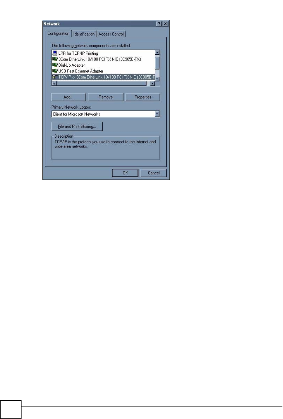
Click Start, Settings, Control Panel and double-click the Network icon to open the Network
window.
Appendix A Setting up Your Computer’s IP Address
NWD210N User’s Guide
82
Figure 53 WIndows 95/98/Me: Network: Configuration
Installing Components
The Network window Configuration tab displays a list of installed components. You need a
network adapter, the TCP/IP protocol and Client for Microsoft Networks.
If you need the adapter:
1In the Network window, click Add.
2Select Adapter and then click Add.
3Select the manufacturer and model of your network adapter and then click OK.
If you need TCP/IP:
1In the Network window, click Add.
2Select Protocol and then click Add.
3Select Microsoft from the list of manufacturers.
4Select TCP/IP from the list of network protocols and then click OK.
If you need Client for Microsoft Networks:
1Click Add.
2Select Client and then click Add.
3Select Microsoft from the list of manufacturers.
4Select Client for Microsoft Networks from the list of network clients and then click
OK.
5Restart your computer so the changes you made take effect.
Appendix A Setting up Your Computer’s IP Address
NWD210N User’s Guide 83
Configuring
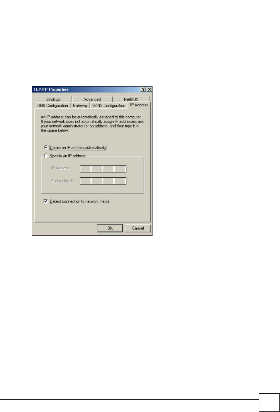
1In the Network window Configuration tab, select your network adapter's TCP/IP entry
and click Properties
2Click the IP Address tab.
• If your IP address is dynamic, select Obtain an IP address automatically.
• If you have a static IP address, select Specify an IP address and type your
information into the IP Address and Subnet Mask fields.
Figure 54 Windows 95/98/Me: TCP/IP Properties: IP Address
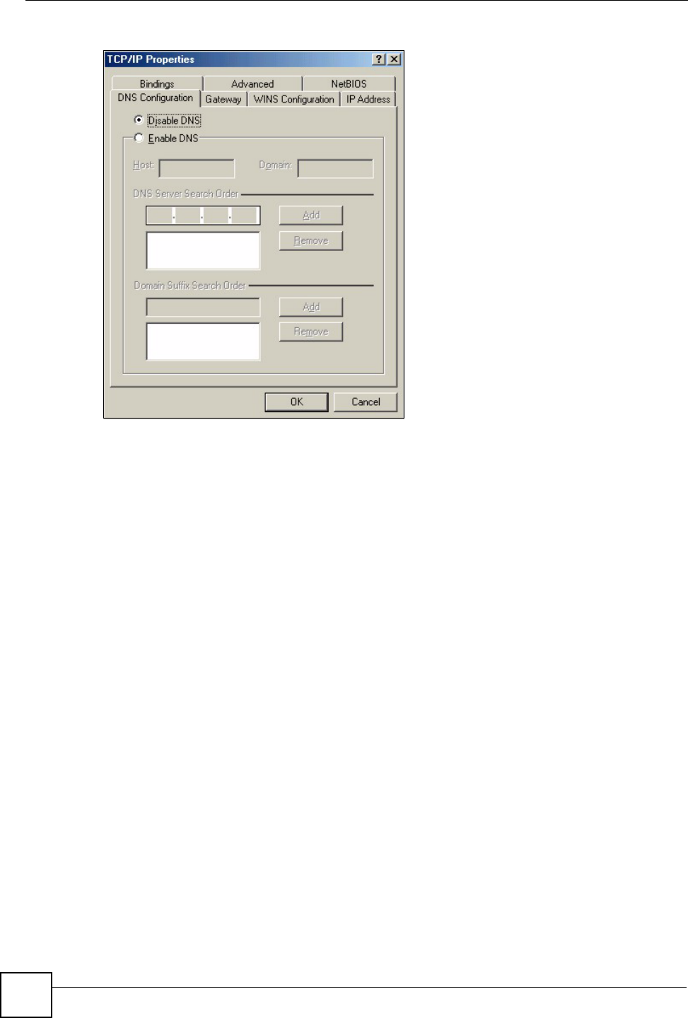
3Click the DNS Configuration tab.
• If you do not know your DNS information, select Disable DNS.
• If you know your DNS information, select Enable DNS and type the information in
the fields below (you may not need to fill them all in).
Appendix A Setting up Your Computer’s IP Address
NWD210N User’s Guide
84
Figure 55 Windows 95/98/Me: TCP/IP Properties: DNS Configuration
4Click the Gateway tab.
• If you do not know your gateway’s IP address, remove previously installed gateways.
• If you have a gateway IP address, type it in the New gateway field and click Add.
5Click OK to save and close the TCP/IP Properties window.
6Click OK to close the Network window. Insert the Windows CD if prompted.
7Turn on your NWD210N and restart your computer when prompted.
Verifying Settings
1Click Start and then Run.
2In the Run window, type "winipcfg" and then click OK to open the IP Configuration
window.
3Select your network adapter. You should see your computer's IP address, subnet mask
and default gateway.
Windows 2000/NT/XP
The following example figures use the default Windows XP GUI theme.
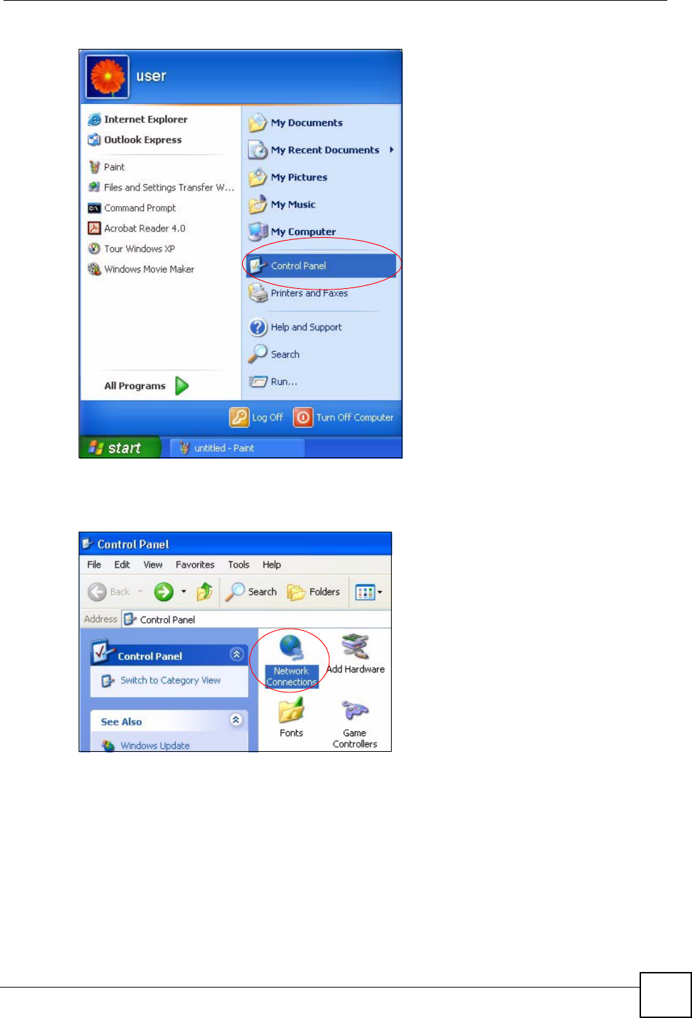
1Click start (Start in Windows 2000/NT), Settings, Control Panel.
Appendix A Setting up Your Computer’s IP Address
NWD210N User’s Guide 85
Figure 56 Windows XP: Start Menu
2In the Control Panel, double-click Network Connections (Network and Dial-up
Connections in Windows 2000/NT).
Figure 57 Windows XP: Control Panel
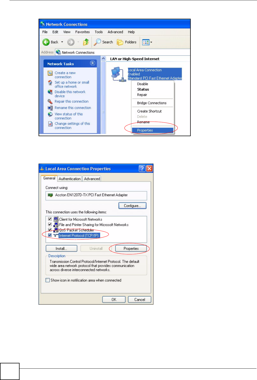
3Right-click Local Area Connection and then click Properties.
Appendix A Setting up Your Computer’s IP Address
NWD210N User’s Guide
86
Figure 58 Windows XP: Control Panel: Network Connections: Properties
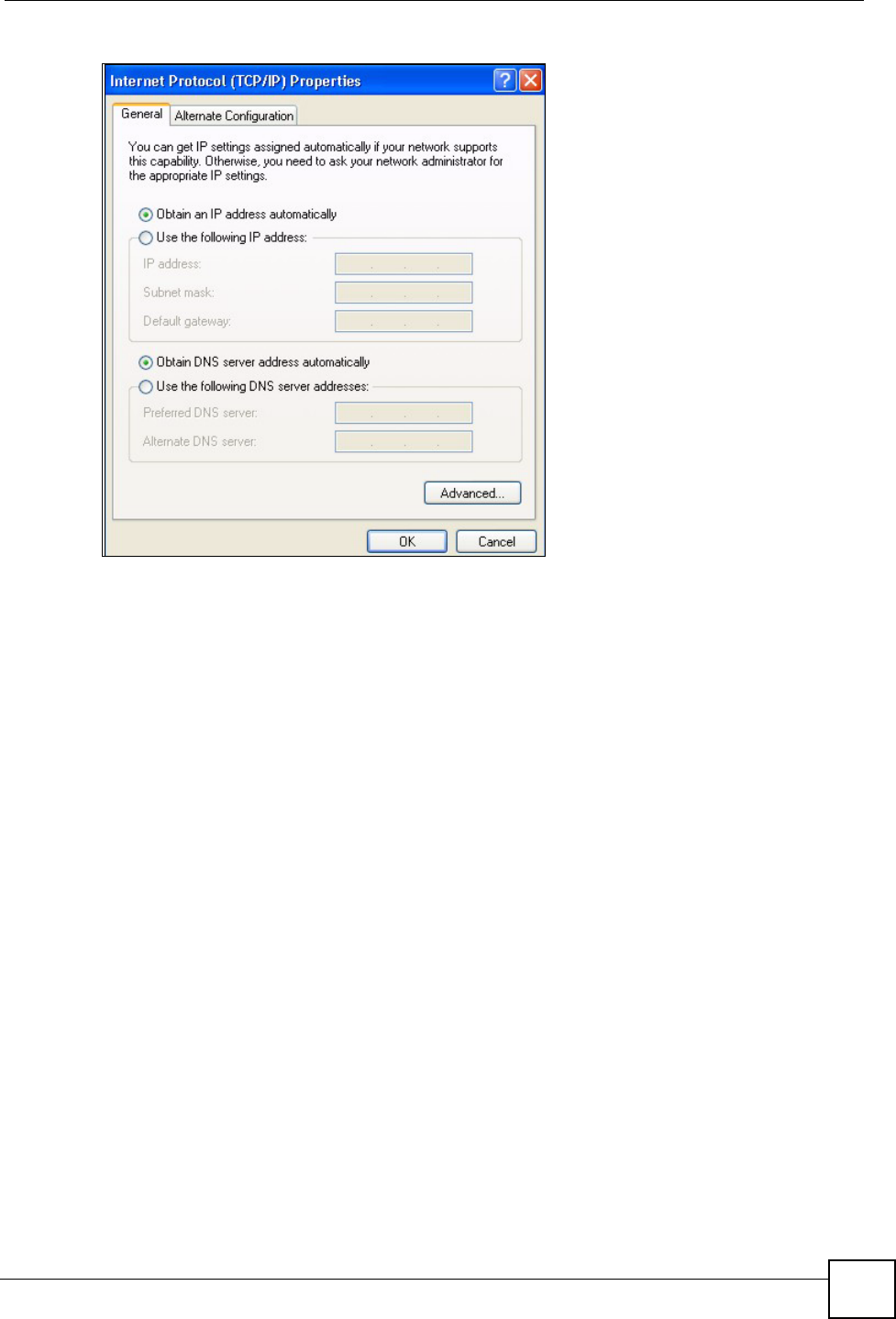
4Select Internet Protocol (TCP/IP) (under the General tab in Win XP) and then click
Properties.
Figure 59 Windows XP: Local Area Connection Properties
5The Internet Protocol TCP/IP Properties window opens (the General tab in Windows
XP).
• If you have a dynamic IP address click Obtain an IP address automatically.
• If you have a static IP address click Use the following IP Address and fill in the IP
address, Subnet mask, and Default gateway fields.
• Click Advanced.
Appendix A Setting up Your Computer’s IP Address
NWD210N User’s Guide 87
Figure 60 Windows XP: Internet Protocol (TCP/IP) Properties
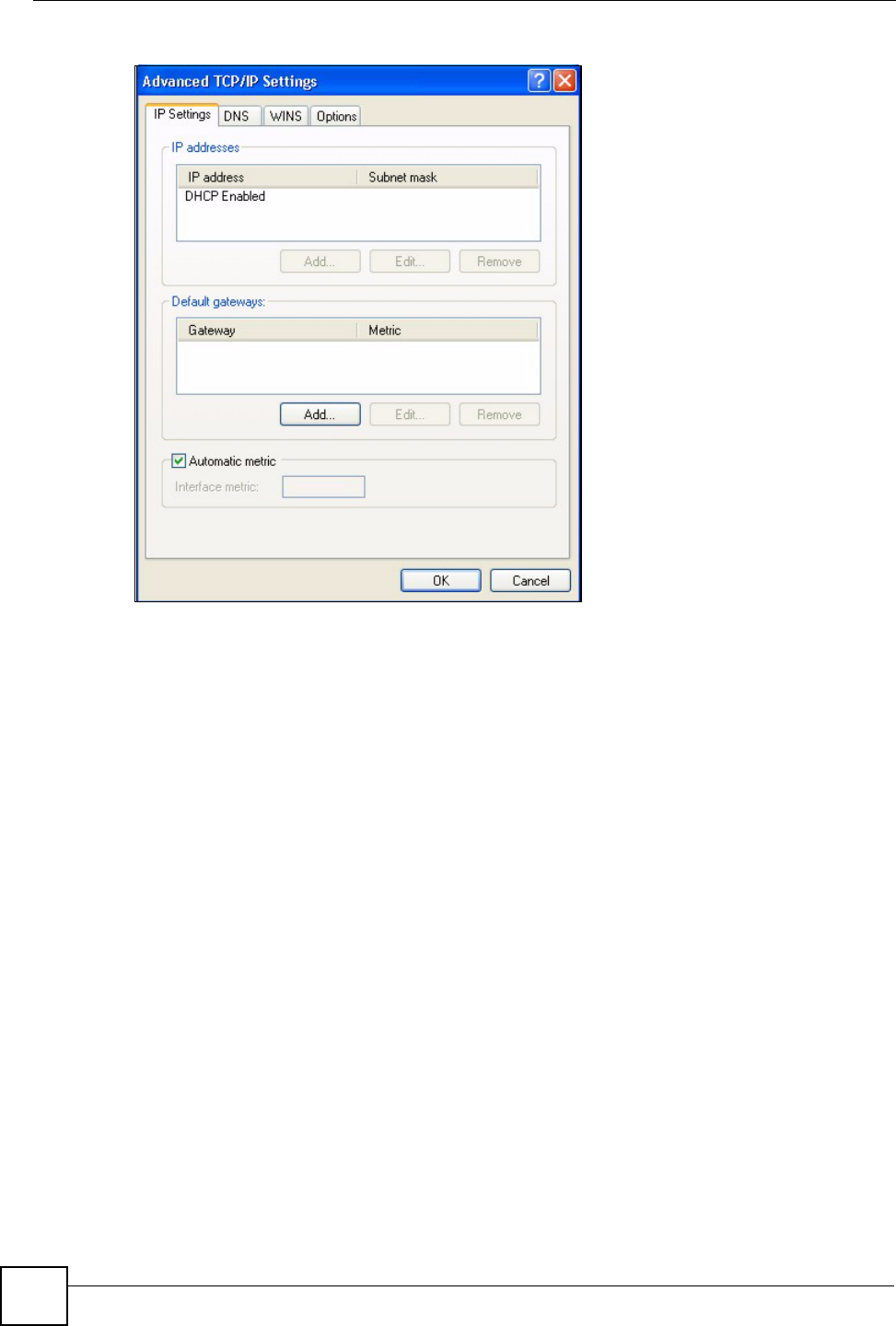
6 If you do not know your gateway's IP address, remove any previously installed
gateways in the IP Settings tab and click OK.
Do one or more of the following if you want to configure additional IP addresses:
•In the IP Settings tab, in IP addresses, click Add.
•In TCP/IP Address, type an IP address in IP address and a subnet mask in Subnet
mask, and then click Add.
• Repeat the above two steps for each IP address you want to add.
• Configure additional default gateways in the IP Settings tab by clicking Add in
Default gateways.
•In TCP/IP Gateway Address, type the IP address of the default gateway in Gateway.
To manually configure a default metric (the number of transmission hops), clear the
Automatic metric check box and type a metric in Metric.
• Click Add.
• Repeat the previous three steps for each default gateway you want to add.
• Click OK when finished.
Appendix A Setting up Your Computer’s IP Address
NWD210N User’s Guide
88
Figure 61 Windows XP: Advanced TCP/IP Properties
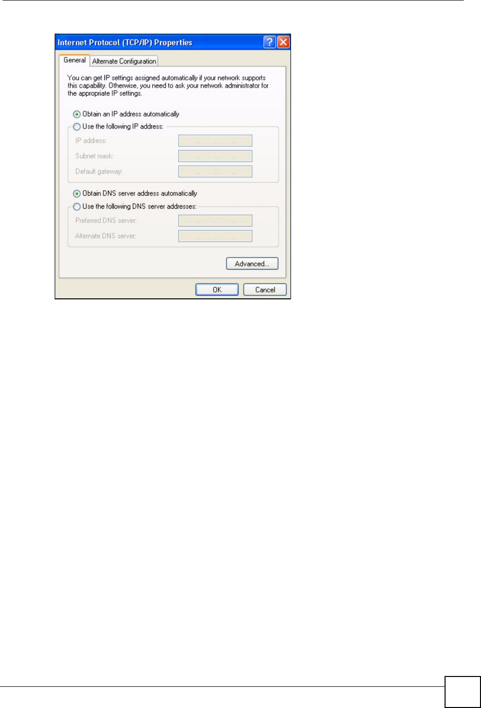
7In the Internet Protocol TCP/IP Properties window (the General tab in Windows
XP):
• Click Obtain DNS server address automatically if you do not know your DNS
server IP address(es).
• If you know your DNS server IP address(es), click Use the following DNS server
addresses, and type them in the Preferred DNS server and Alternate DNS server
fields.
If you have previously configured DNS servers, click Advanced and then the DNS
tab to order them.
Appendix A Setting up Your Computer’s IP Address
NWD210N User’s Guide 89
Figure 62 Windows XP: Internet Protocol (TCP/IP) Properties
8Click OK to close the Internet Protocol (TCP/IP) Properties window.
9Click Close (OK in Windows 2000/NT) to close the Local Area Connection
Properties window.
10 Close the Network Connections window (Network and Dial-up Connections in
Windows 2000/NT).
11 Turn on your NWD210N and restart your computer (if prompted).
Verifying Settings
1Click Start, All Programs, Accessories and then Command Prompt.
2In the Command Prompt window, type "ipconfig" and then press [ENTER]. You can
also open Network Connections, right-click a network connection, click Status and
then click the Support tab.
Windows Vista
This section shows screens from Windows Vista Enterprise Version 6.0.
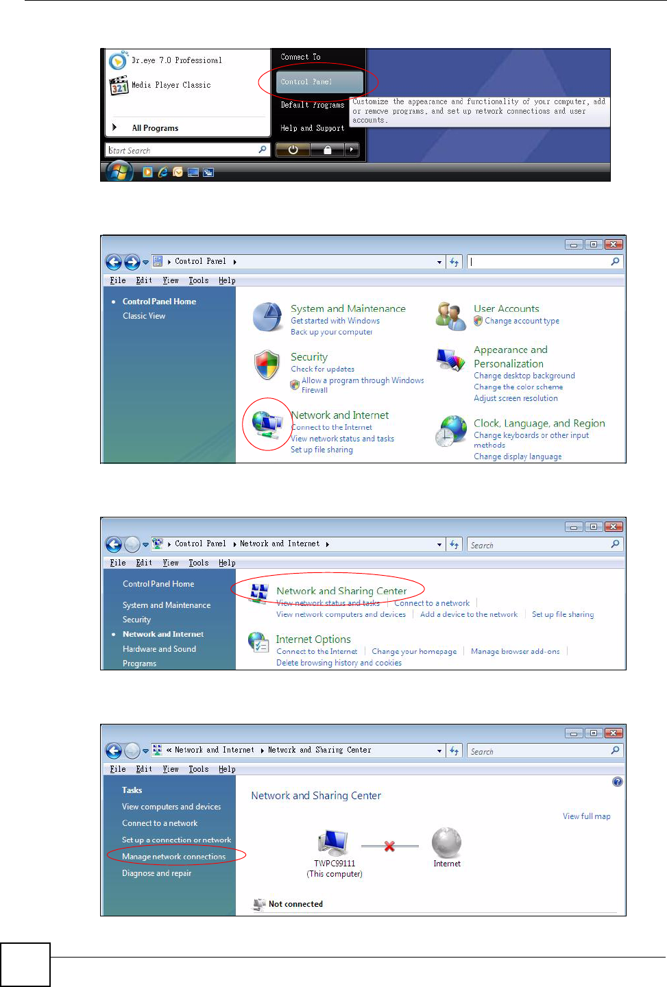
1Click the Start icon, Control Panel.
Appendix A Setting up Your Computer’s IP Address
NWD210N User’s Guide
90
Figure 63 Windows Vista: Start Menu
2In the Control Panel, double-click Network and Internet.
Figure 64 Windows Vista: Control Panel
3Click Network and Sharing Center.
Figure 65 Windows Vista: Network And Internet
4Click Manage network connections.
Figure 66 Windows Vista: Network and Sharing Center
Appendix A Setting up Your Computer’s IP Address
NWD210N User’s Guide 91
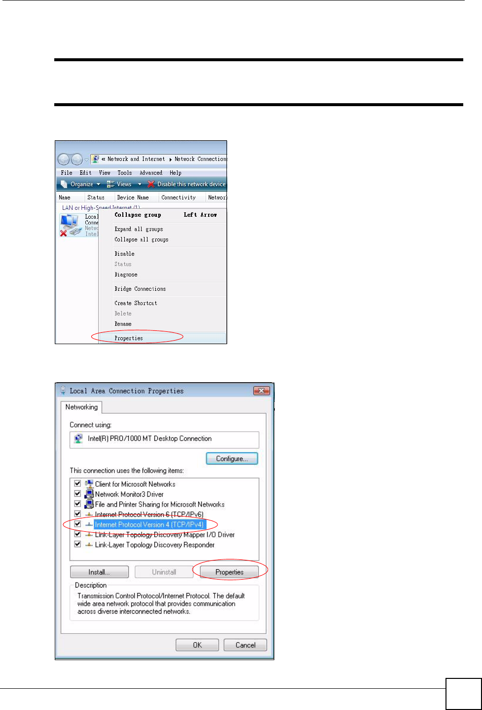
5Right-click Local Area Connection and then click Properties.
"During this procedure, click Continue whenever Windows displays a screen
saying that it needs your permission to continue.
Figure 67 Windows Vista: Network and Sharing Center
6Select Internet Protocol Version 4 (TCP/IPv4) and click Properties.
Figure 68 Windows Vista: Local Area Connection Properties
Appendix A Setting up Your Computer’s IP Address
NWD210N User’s Guide
92
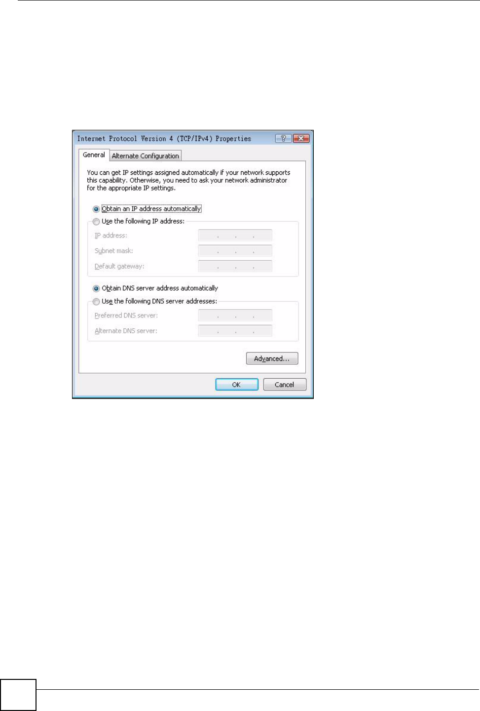
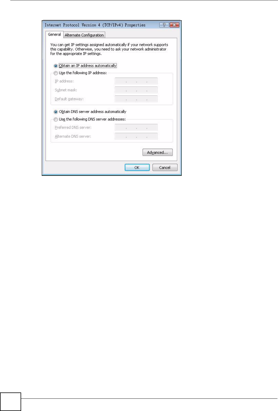
7The Internet Protocol Version 4 (TCP/IPv4) Properties window opens (the General
tab).
• If you have a dynamic IP address click Obtain an IP address automatically.
• If you have a static IP address click Use the following IP address and fill in the IP
address, Subnet mask, and Default gateway fields.
• Click Advanced.
Figure 69 Windows Vista: Internet Protocol Version 4 (TCP/IPv4) Properties
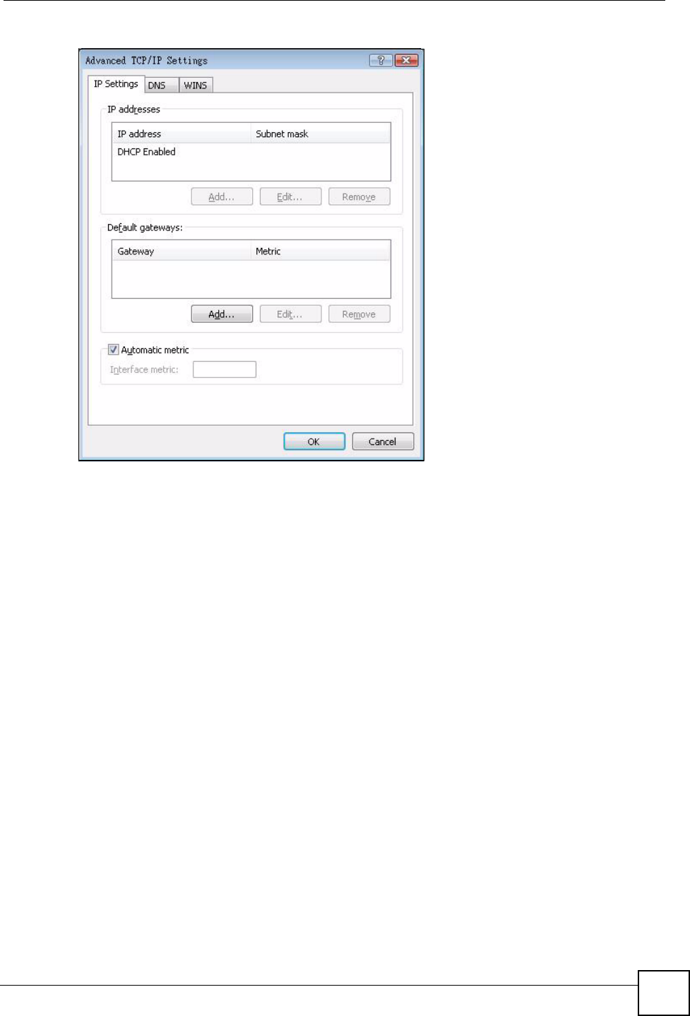
8 If you do not know your gateway's IP address, remove any previously installed
gateways in the IP Settings tab and click OK.
Do one or more of the following if you want to configure additional IP addresses:
•In the IP Settings tab, in IP addresses, click Add.
•In TCP/IP Address, type an IP address in IP address and a subnet mask in Subnet
mask, and then click Add.
• Repeat the above two steps for each IP address you want to add.
• Configure additional default gateways in the IP Settings tab by clicking Add in
Default gateways.
•In TCP/IP Gateway Address, type the IP address of the default gateway in Gateway.
To manually configure a default metric (the number of transmission hops), clear the
Automatic metric check box and type a metric in Metric.
• Click Add.
• Repeat the previous three steps for each default gateway you want to add.
• Click OK when finished.
Appendix A Setting up Your Computer’s IP Address
NWD210N User’s Guide 93
Figure 70 Windows Vista: Advanced TCP/IP Properties
9In the Internet Protocol Version 4 (TCP/IPv4) Properties window, (the General tab):
• Click Obtain DNS server address automatically if you do not know your DNS
server IP address(es).
• If you know your DNS server IP address(es), click Use the following DNS server
addresses, and type them in the Preferred DNS server and Alternate DNS server
fields.
If you have previously configured DNS servers, click Advanced and then the DNS
tab to order them.
Appendix A Setting up Your Computer’s IP Address
NWD210N User’s Guide
94
Figure 71 Windows Vista: Internet Protocol Version 4 (TCP/IPv4) Properties
10 Click OK to close the Internet Protocol Version 4 (TCP/IPv4) Properties window.
11 Click Close to close the Local Area Connection Properties window.
12 Close the Network Connections window.
13 Turn on your NWD210N and restart your computer (if prompted).
Verifying Settings
1Click Start, All Programs, Accessories and then Command Prompt.
2In the Command Prompt window, type "ipconfig" and then press [ENTER]. You can
also open Network Connections, right-click a network connection, click Status and
then click the Support tab.
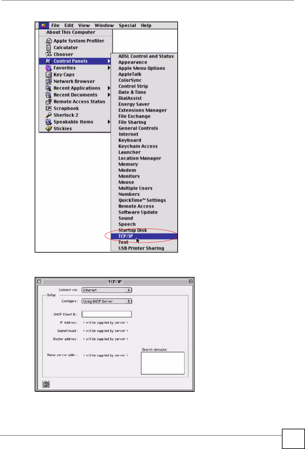
Macintosh OS 8/9
1Click the Apple menu, Control Panel and double-click TCP/IP to open the TCP/IP
Control Panel.
Appendix A Setting up Your Computer’s IP Address
NWD210N User’s Guide 95
Figure 72 Macintosh OS 8/9: Apple Menu
2Select Ethernet built-in from the Connect via list.
Figure 73 Macintosh OS 8/9: TCP/IP
3For dynamically assigned settings, select Using DHCP Server from the Configure: list.
4For statically assigned settings, do the following:
•From the Configure box, select Manually.
Appendix A Setting up Your Computer’s IP Address
NWD210N User’s Guide
96
• Type your IP address in the IP Address box.
• Type your subnet mask in the Subnet mask box.
• Type the IP address of your NWD210N in the Router address box.
5Close the TCP/IP Control Panel.
6Click Save if prompted, to save changes to your configuration.
7Turn on your NWD210N and restart your computer (if prompted).
Verifying Settings
Check your TCP/IP properties in the TCP/IP Control Panel window.
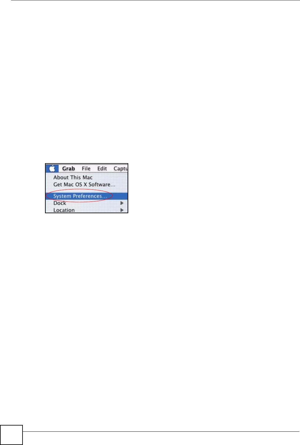
Macintosh OS X
1Click the Apple menu, and click System Preferences to open the System Preferences
window.
Figure 74 Macintosh OS X: Apple Menu
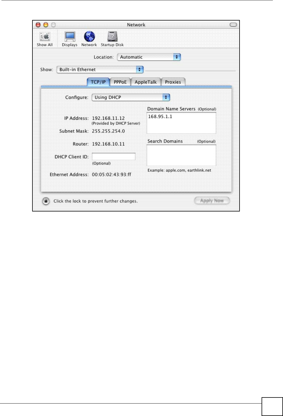
2Click Network in the icon bar.
• Select Automatic from the Location list.
• Select Built-in Ethernet from the Show list.
• Click the TCP/IP tab.
3For dynamically assigned settings, select Using DHCP from the Configure list.
Appendix A Setting up Your Computer’s IP Address
NWD210N User’s Guide 97
Figure 75 Macintosh OS X: Network
4For statically assigned settings, do the following:
•From the Configure box, select Manually.
• Type your IP address in the IP Address box.
• Type your subnet mask in the Subnet mask box.
• Type the IP address of your NWD210N in the Router address box.
5Click Apply Now and close the window.
6Turn on your NWD210N and restart your computer (if prompted).
Verifying Settings
Check your TCP/IP properties in the Network window.
Linux
This section shows you how to configure your computer’s TCP/IP settings in Red Hat Linux
9.0. Procedure, screens and file location may vary depending on your Linux distribution and
release version.
Appendix A Setting up Your Computer’s IP Address
NWD210N User’s Guide
98
"Make sure you are logged in as the root administrator.
Using the K Desktop Environment (KDE)
Follow the steps below to configure your computer IP address using the KDE.
1Click the Red Hat button (located on the bottom left corner), select System Setting and
click Network.
Figure 76 Red Hat 9.0: KDE: Network Configuration: Devices
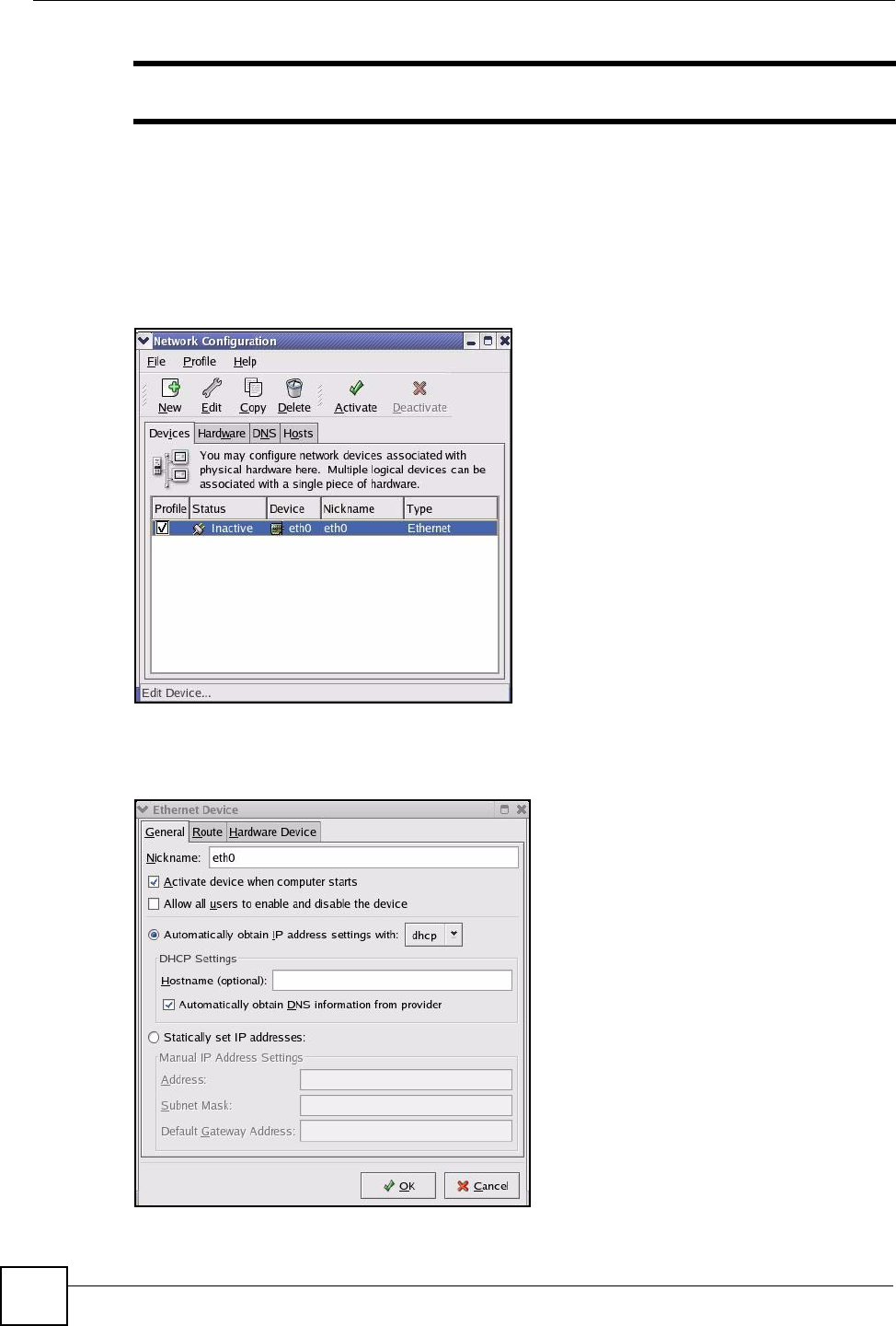
2Double-click on the profile of the network card you wish to configure. The Ethernet
Device General screen displays as shown.
Figure 77 Red Hat 9.0: KDE: Ethernet Device: General
Appendix A Setting up Your Computer’s IP Address
NWD210N User’s Guide 99
• If you have a dynamic IP address, click Automatically obtain IP address settings
with and select dhcp from the drop down list.
• If you have a static IP address, click Statically set IP Addresses and fill in the
Address, Subnet mask, and Default Gateway Address fields.
3Click OK to save the changes and close the Ethernet Device General screen.
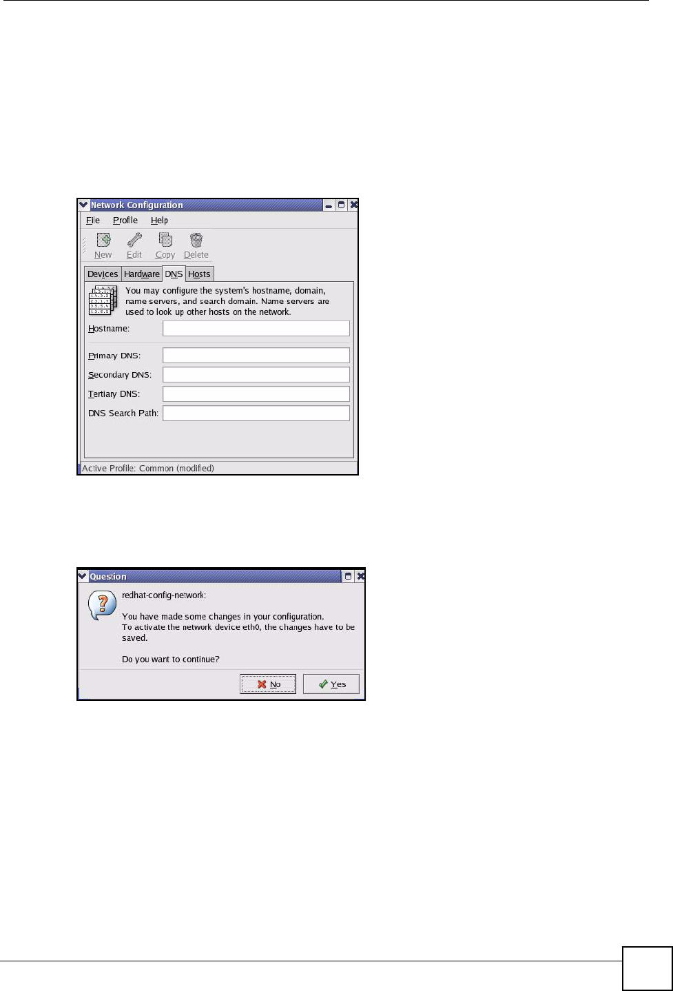
4If you know your DNS server IP address(es), click the DNS tab in the Network
Configuration screen. Enter the DNS server information in the fields provided.
Figure 78 Red Hat 9.0: KDE: Network Configuration: DNS
5Click the Devices tab.
6Click the Activate button to apply the changes. The following screen displays. Click Yes
to save the changes in all screens.
Figure 79 Red Hat 9.0: KDE: Network Configuration: Activate
7After the network card restart process is complete, make sure the Status is Active in the
Network Configuration screen.
Using Configuration Files
Follow the steps below to edit the network configuration files and set your computer IP
address.
1Assuming that you have only one network card on the computer, locate the ifconfig-
eth0 configuration file (where eth0 is the name of the Ethernet card). Open the
configuration file with any plain text editor.
• If you have a dynamic IP address, enter dhcp in the BOOTPROTO= field. The
following figure shows an example.

Appendix A Setting up Your Computer’s IP Address
NWD210N User’s Guide
100
Figure 80 Red Hat 9.0: Dynamic IP Address Setting in ifconfig-eth0
• If you have a static IP address, enter static in the BOOTPROTO= field. Type
IPADDR= followed by the IP address (in dotted decimal notation) and type NETMASK=
followed by the subnet mask. The following example shows an example where the
static IP address is 192.168.1.10 and the subnet mask is 255.255.255.0.
Figure 81 Red Hat 9.0: Static IP Address Setting in ifconfig-eth0
2If you know your DNS server IP address(es), enter the DNS server information in the
resolv.conf file in the /etc directory. The following figure shows an example where
two DNS server IP addresses are specified.
Figure 82 Red Hat 9.0: DNS Settings in resolv.conf
3After you edit and save the configuration files, you must restart the network card. Enter
./network restart in the /etc/rc.d/init.d directory. The following figure
shows an example.
Figure 83 Red Hat 9.0: Restart Ethernet Card
DEVICE=eth0
ONBOOT=yes
BOOTPROTO=dhcp
USERCTL=no
PEERDNS=yes
TYPE=Ethernet
DEVICE=eth0
ONBOOT=yes
BOOTPROTO=static
IPADDR=192.168.1.10
NETMASK=255.255.255.0
USERCTL=no
PEERDNS=yes
TYPE=Ethernet
nameserver 172.23.5.1
nameserver 172.23.5.2
[root@localhost init.d]# network restart
Shutting down interface eth0: [OK]
Shutting down loopback interface: [OK]
Setting network parameters: [OK]
Bringing up loopback interface: [OK]
Bringing up interface eth0: [OK]

Appendix A Setting up Your Computer’s IP Address
NWD210N User’s Guide 101
Verifying Settings
Enter ifconfig in a terminal screen to check your TCP/IP properties.
Figure 84 Red Hat 9.0: Checking TCP/IP Properties
[root@localhost]# ifconfig
eth0 Link encap:Ethernet HWaddr 00:50:BA:72:5B:44
inet addr:172.23.19.129 Bcast:172.23.19.255 Mask:255.255.255.0
UP BROADCAST RUNNING MULTICAST MTU:1500 Metric:1
RX packets:717 errors:0 dropped:0 overruns:0 frame:0
TX packets:13 errors:0 dropped:0 overruns:0 carrier:0
collisions:0 txqueuelen:100
RX bytes:730412 (713.2 Kb) TX bytes:1570 (1.5 Kb)
Interrupt:10 Base address:0x1000
[root@localhost]#

Appendix A Setting up Your Computer’s IP Address
NWD210N User’s Guide
102
NWD210N User’s Guide 103
APPENDIX B
Wireless LANs
Wireless LAN Topologies
This section discusses ad-hoc and infrastructure wireless LAN topologies.
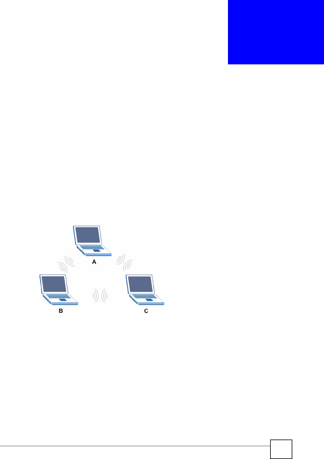
Ad-hoc Wireless LAN Configuration
The simplest WLAN configuration is an independent (Ad-hoc) WLAN that connects a set of
computers with wireless adapters (A, B, C). Any time two or more wireless adapters are within
range of each other, they can set up an independent network, which is commonly referred to as
an ad-hoc network or Independent Basic Service Set (IBSS). The following diagram shows an
example of notebook computers using wireless adapters to form an ad-hoc wireless LAN.
Figure 85 Peer-to-Peer Communication in an Ad-hoc Network
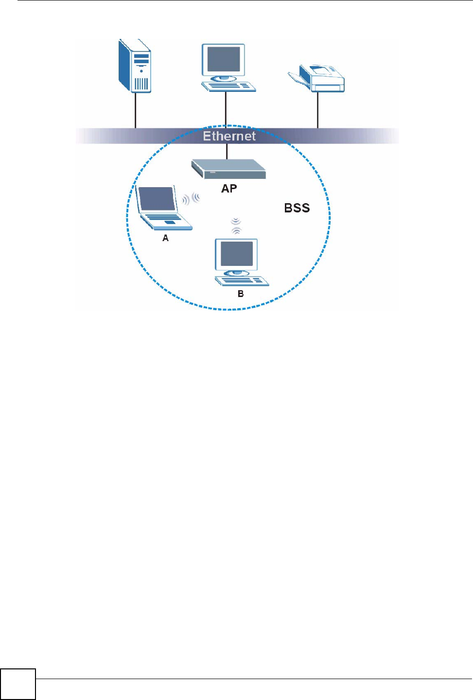
BSS
A Basic Service Set (BSS) exists when all communications between wireless clients or
between a wireless client and a wired network client go through one access point (AP).
Intra-BSS traffic is traffic between wireless clients in the BSS. When Intra-BSS is enabled,
wireless client A and B can access the wired network and communicate with each other. When
Intra-BSS is disabled, wireless client A and B can still access the wired network but cannot
communicate with each other.
Appendix B Wireless LANs
NWD210N User’s Guide
104
Figure 86 Basic Service Set
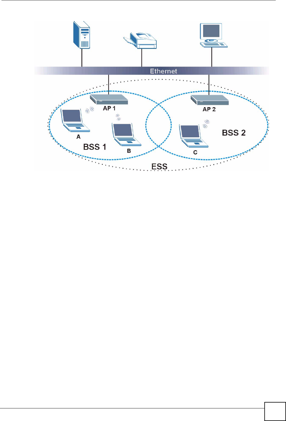
ESS
An Extended Service Set (ESS) consists of a series of overlapping BSSs, each containing an
access point, with each access point connected together by a wired network. This wired
connection between APs is called a Distribution System (DS).
This type of wireless LAN topology is called an Infrastructure WLAN. The Access Points not
only provide communication with the wired network but also mediate wireless network traffic
in the immediate neighborhood.
An ESSID (ESS IDentification) uniquely identifies each ESS. All access points and their
associated wireless clients within the same ESS must have the same ESSID in order to
communicate.
Appendix B Wireless LANs
NWD210N User’s Guide 105
Figure 87 Infrastructure WLAN
Channel
A channel is the radio frequency(ies) used by wireless devices to transmit and receive data.
Channels available depend on your geographical area. You may have a choice of channels (for
your region) so you should use a channel different from an adjacent AP (access point) to
reduce interference. Interference occurs when radio signals from different access points
overlap causing interference and degrading performance.
Adjacent channels partially overlap however. To avoid interference due to overlap, your AP
should be on a channel at least five channels away from a channel that an adjacent AP is using.
For example, if your region has 11 channels and an adjacent AP is using channel 1, then you
need to select a channel between 6 or 11.
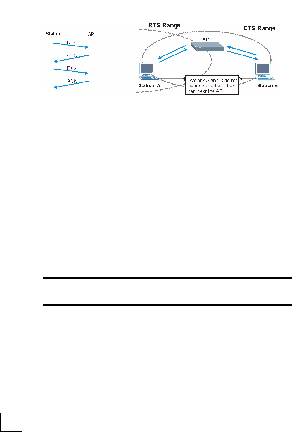
RTS/CTS
A hidden node occurs when two stations are within range of the same access point, but are not
within range of each other. The following figure illustrates a hidden node. Both stations (STA)
are within range of the access point (AP) or wireless gateway, but out-of-range of each other,
so they cannot "hear" each other, that is they do not know if the channel is currently being
used. Therefore, they are considered hidden from each other.
Appendix B Wireless LANs
NWD210N User’s Guide
106
Figure 88 RTS/CTS
When station A sends data to the AP, it might not know that the station B is already using the
channel. If these two stations send data at the same time, collisions may occur when both sets
of data arrive at the AP at the same time, resulting in a loss of messages for both stations.
RTS/CTS is designed to prevent collisions due to hidden nodes. An RTS/CTS defines the
biggest size data frame you can send before an RTS (Request To Send)/CTS (Clear to Send)
handshake is invoked.
When a data frame exceeds the RTS/CTS value you set (between 0 to 2432 bytes), the station
that wants to transmit this frame must first send an RTS (Request To Send) message to the AP
for permission to send it. The AP then responds with a CTS (Clear to Send) message to all
other stations within its range to notify them to defer their transmission. It also reserves and
confirms with the requesting station the time frame for the requested transmission.
Stations can send frames smaller than the specified RTS/CTS directly to the AP without the
RTS (Request To Send)/CTS (Clear to Send) handshake.
You should only configure RTS/CTS if the possibility of hidden nodes exists on your network
and the "cost" of resending large frames is more than the extra network overhead involved in
the RTS (Request To Send)/CTS (Clear to Send) handshake.
If the RTS/CTS value is greater than the Fragmentation Threshold value (see next), then the
RTS (Request To Send)/CTS (Clear to Send) handshake will never occur as data frames will
be fragmented before they reach RTS/CTS size.
"Enabling the RTS Threshold causes redundant network overhead that could
negatively affect the throughput performance instead of providing a remedy.
Fragmentation Threshold
A Fragmentation Threshold is the maximum data fragment size (between 256 and 2432
bytes) that can be sent in the wireless network before the AP will fragment the packet into
smaller data frames.
A large Fragmentation Threshold is recommended for networks not prone to interference
while you should set a smaller threshold for busy networks or networks that are prone to
interference.

Appendix B Wireless LANs
NWD210N User’s Guide 107
If the Fragmentation Threshold value is smaller than the RTS/CTS value (see previously)
you set then the RTS (Request To Send)/CTS (Clear to Send) handshake will never occur as
data frames will be fragmented before they reach RTS/CTS size.
Preamble Type
Preamble is used to signal that data is coming to the receiver. Short and long refer to the length
of the synchronization field in a packet.
Short preamble increases performance as less time sending preamble means more time for
sending data. All IEEE 802.11 compliant wireless adapters support long preamble, but not all
support short preamble.
Use long preamble if you are unsure what preamble mode other wireless devices on the
network support, and to provide more reliable communications in busy wireless networks.
Use short preamble if you are sure all wireless devices on the network support it, and to
provide more efficient communications.
Use the dynamic setting to automatically use short preamble when all wireless devices on the
network support it, otherwise the NWD210N uses long preamble.
"The wireless devices MUST use the same preamble mode in order to
communicate.
IEEE 802.11g Wireless LAN
IEEE 802.11g is fully compatible with the IEEE 802.11b standard. This means an IEEE
802.11b adapter can interface directly with an IEEE 802.11g access point (and vice versa) at
11 Mbps or lower depending on range. IEEE 802.11g has several intermediate rate steps
between the maximum and minimum data rates. The IEEE 802.11g data rate and modulation
are as follows:
Wireless Security Overview
Wireless security is vital to your network to protect wireless communication between wireless
clients, access points and the wired network.
Table 22 IEEE 802.11g
DATA RATE (MBPS) MODULATION
1 DBPSK (Differential Binary Phase Shift Keyed)
2 DQPSK (Differential Quadrature Phase Shift Keying)
5.5 / 11 CCK (Complementary Code Keying)
6/9/12/18/24/36/48/54 OFDM (Orthogonal Frequency Division Multiplexing)

Appendix B Wireless LANs
NWD210N User’s Guide
108
Wireless security methods available on the NWD210N are data encryption, wireless client
authentication, restricting access by device MAC address and hiding the NWD210N identity.
The following figure shows the relative effectiveness of these wireless security methods
available on your NWD210N.
"You must enable the same wireless security settings on the NWD210N and on
all wireless clients that you want to associate with it.
IEEE 802.1x
In June 2001, the IEEE 802.1x standard was designed to extend the features of IEEE 802.11 to
support extended authentication as well as providing additional accounting and control
features. It is supported by Windows XP and a number of network devices. Some advantages
of IEEE 802.1x are:
• User based identification that allows for roaming.
• Support for RADIUS (Remote Authentication Dial In User Service, RFC 2138, 2139) for
centralized user profile and accounting management on a network RADIUS server.
• Support for EAP (Extensible Authentication Protocol, RFC 2486) that allows additional
authentication methods to be deployed with no changes to the access point or the wireless
clients.
RADIUS
RADIUS is based on a client-server model that supports authentication, authorization and
accounting. The access point is the client and the server is the RADIUS server. The RADIUS
server handles the following tasks:
• Authentication
Determines the identity of the users.
• Authorization
Table 23 Wireless Security Levels
SECURITY
LEVEL SECURITY TYPE
Least
S e c u r e
Most Secure
Unique SSID (Default)
Unique SSID with Hide SSID Enabled
MAC Address Filtering
WEP Encryption
IEEE802.1x EAP with RADIUS Server Authentication
Wi-Fi Protected Access (WPA)
WPA2

Appendix B Wireless LANs
NWD210N User’s Guide 109
Determines the network services available to authenticated users once they are connected
to the network.
• Accounting
Keeps track of the client’s network activity.
RADIUS is a simple package exchange in which your AP acts as a message relay between the
wireless client and the network RADIUS server.
Types of RADIUS Messages
The following types of RADIUS messages are exchanged between the access point and the
RADIUS server for user authentication:
• Access-Request
Sent by an access point requesting authentication.
• Access-Reject
Sent by a RADIUS server rejecting access.
• Access-Accept
Sent by a RADIUS server allowing access.
• Access-Challenge
Sent by a RADIUS server requesting more information in order to allow access. The
access point sends a proper response from the user and then sends another Access-Request
message.
The following types of RADIUS messages are exchanged between the access point and the
RADIUS server for user accounting:
• Accounting-Request
Sent by the access point requesting accounting.
• Accounting-Response
Sent by the RADIUS server to indicate that it has started or stopped accounting.
In order to ensure network security, the access point and the RADIUS server use a shared
secret key, which is a password, they both know. The key is not sent over the network. In
addition to the shared key, password information exchanged is also encrypted to protect the
network from unauthorized access.
Types of EAP Authentication
This section discusses some popular authentication types: EAP-MD5, EAP-TLS, EAP-TTLS,
PEAP and LEAP. Your wireless LAN device may not support all authentication types.
EAP (Extensible Authentication Protocol) is an authentication protocol that runs on top of the
IEEE 802.1x transport mechanism in order to support multiple types of user authentication. By
using EAP to interact with an EAP-compatible RADIUS server, an access point helps a
wireless station and a RADIUS server perform authentication.
The type of authentication you use depends on the RADIUS server and an intermediary AP(s)
that supports IEEE 802.1x. .

Appendix B Wireless LANs
NWD210N User’s Guide
110
For EAP-TLS authentication type, you must first have a wired connection to the network and
obtain the certificate(s) from a certificate authority (CA). A certificate (also called digital IDs)
can be used to authenticate users and a CA issues certificates and guarantees the identity of
each certificate owner.
EAP-MD5 (Message-Digest Algorithm 5)
MD5 authentication is the simplest one-way authentication method. The authentication server
sends a challenge to the wireless client. The wireless client ‘proves’ that it knows the password
by encrypting the password with the challenge and sends back the information. Password is
not sent in plain text.
However, MD5 authentication has some weaknesses. Since the authentication server needs to
get the plaintext passwords, the passwords must be stored. Thus someone other than the
authentication server may access the password file. In addition, it is possible to impersonate an
authentication server as MD5 authentication method does not perform mutual authentication.
Finally, MD5 authentication method does not support data encryption with dynamic session
key. You must configure WEP encryption keys for data encryption.
EAP-TLS (Transport Layer Security)
With EAP-TLS, digital certifications are needed by both the server and the wireless clients for
mutual authentication. The server presents a certificate to the client. After validating the
identity of the server, the client sends a different certificate to the server. The exchange of
certificates is done in the open before a secured tunnel is created. This makes user identity
vulnerable to passive attacks. A digital certificate is an electronic ID card that authenticates the
sender’s identity. However, to implement EAP-TLS, you need a Certificate Authority (CA) to
handle certificates, which imposes a management overhead.
EAP-TTLS (Tunneled Transport Layer Service)
EAP-TTLS is an extension of the EAP-TLS authentication that uses certificates for only the
server-side authentications to establish a secure connection. Client authentication is then done
by sending username and password through the secure connection, thus client identity is
protected. For client authentication, EAP-TTLS supports EAP methods and legacy
authentication methods such as PAP, CHAP, MS-CHAP and MS-CHAP v2.
PEAP (Protected EAP)
Like EAP-TTLS, server-side certificate authentication is used to establish a secure connection,
then use simple username and password methods through the secured connection to
authenticate the clients, thus hiding client identity. However, PEAP only supports EAP
methods, such as EAP-MD5, EAP-MSCHAPv2 and EAP-GTC (EAP-Generic Token Card),
for client authentication. EAP-GTC is implemented only by Cisco.
LEAP
LEAP (Lightweight Extensible Authentication Protocol) is a Cisco implementation of IEEE
802.1x.

Appendix B Wireless LANs
NWD210N User’s Guide 111
Dynamic WEP Key Exchange
The AP maps a unique key that is generated with the RADIUS server. This key expires when
the wireless connection times out, disconnects or reauthentication times out. A new WEP key
is generated each time reauthentication is performed.
If this feature is enabled, it is not necessary to configure a default encryption key in the
wireless security configuration screen. You may still configure and store keys, but they will
not be used while dynamic WEP is enabled.
"EAP-MD5 cannot be used with Dynamic WEP Key Exchange
For added security, certificate-based authentications (EAP-TLS, EAP-TTLS and PEAP) use
dynamic keys for data encryption. They are often deployed in corporate environments, but for
public deployment, a simple user name and password pair is more practical. The following
table is a comparison of the features of authentication types.
WPA and WPA2
Wi-Fi Protected Access (WPA) is a subset of the IEEE 802.11i standard. WPA2 (IEEE
802.11i) is a wireless security standard that defines stronger encryption, authentication and
key management than WPA.
Key differences between WPA or WPA2 and WEP are improved data encryption and user
authentication.
If both an AP and the wireless clients support WPA2 and you have an external RADIUS
server, use WPA2 for stronger data encryption. If you don't have an external RADIUS server,
you should use WPA2-PSK (WPA2-Pre-Shared Key) that only requires a single (identical)
password entered into each access point, wireless gateway and wireless client. As long as the
passwords match, a wireless client will be granted access to a WLAN.
If the AP or the wireless clients do not support WPA2, just use WPA or WPA-PSK depending
on whether you have an external RADIUS server or not.
Select WEP only when the AP and/or wireless clients do not support WPA or WPA2. WEP is
less secure than WPA or WPA2.
Table 24 Comparison of EAP Authentication Types
EAP-MD5 EAP-TLS EAP-TTLS PEAP LEAP
Mutual Authentication No Yes Yes Yes Yes
Certificate – Client No Yes Optional Optional No
Certificate – Server No Yes Yes Yes No
Dynamic Key Exchange No Yes Yes Yes Yes
Credential Integrity None Strong Strong Strong Moderate
Deployment Difficulty Easy Hard Moderate Moderate Moderate
Client Identity Protection No No Yes Yes No