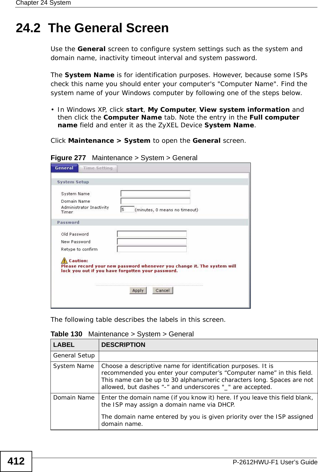
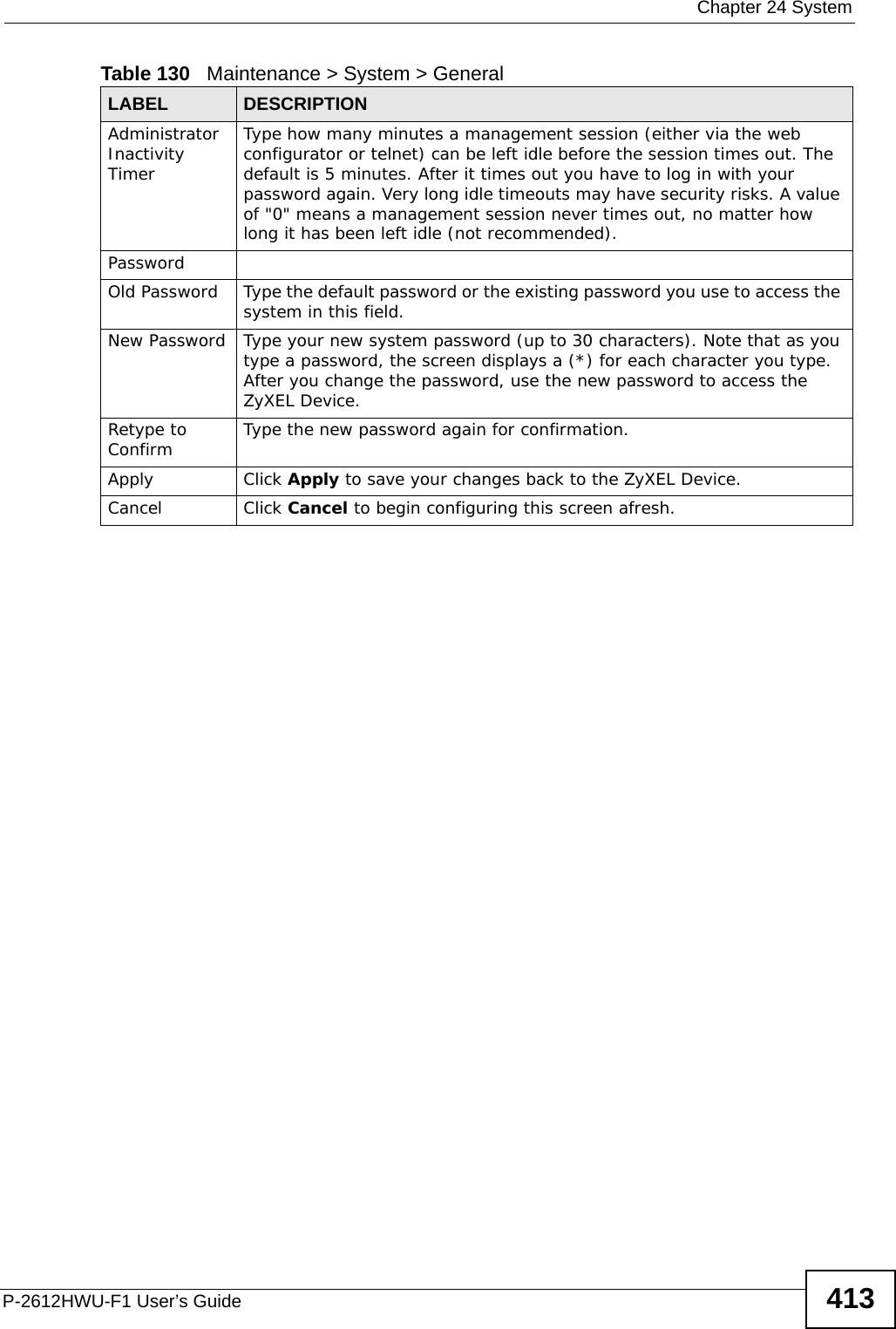
ZyXEL Communications P2612HWUFX Dual WAN ADSL2+ VoIP IAD User Manual SMG 700 User s Guide V1 00 Nov 2004
ZyXEL Communications Corporation Dual WAN ADSL2+ VoIP IAD SMG 700 User s Guide V1 00 Nov 2004
Contents
- 1. manual part 3
- 2. Usermanual part 1
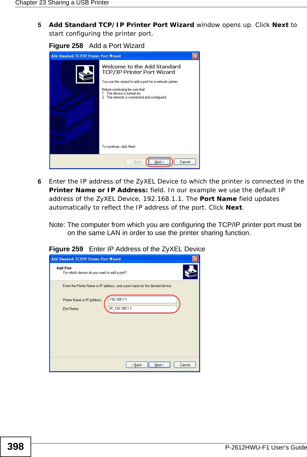
- 3. Usermanual part 2
- 4. Usermanual part 4
manual part 3


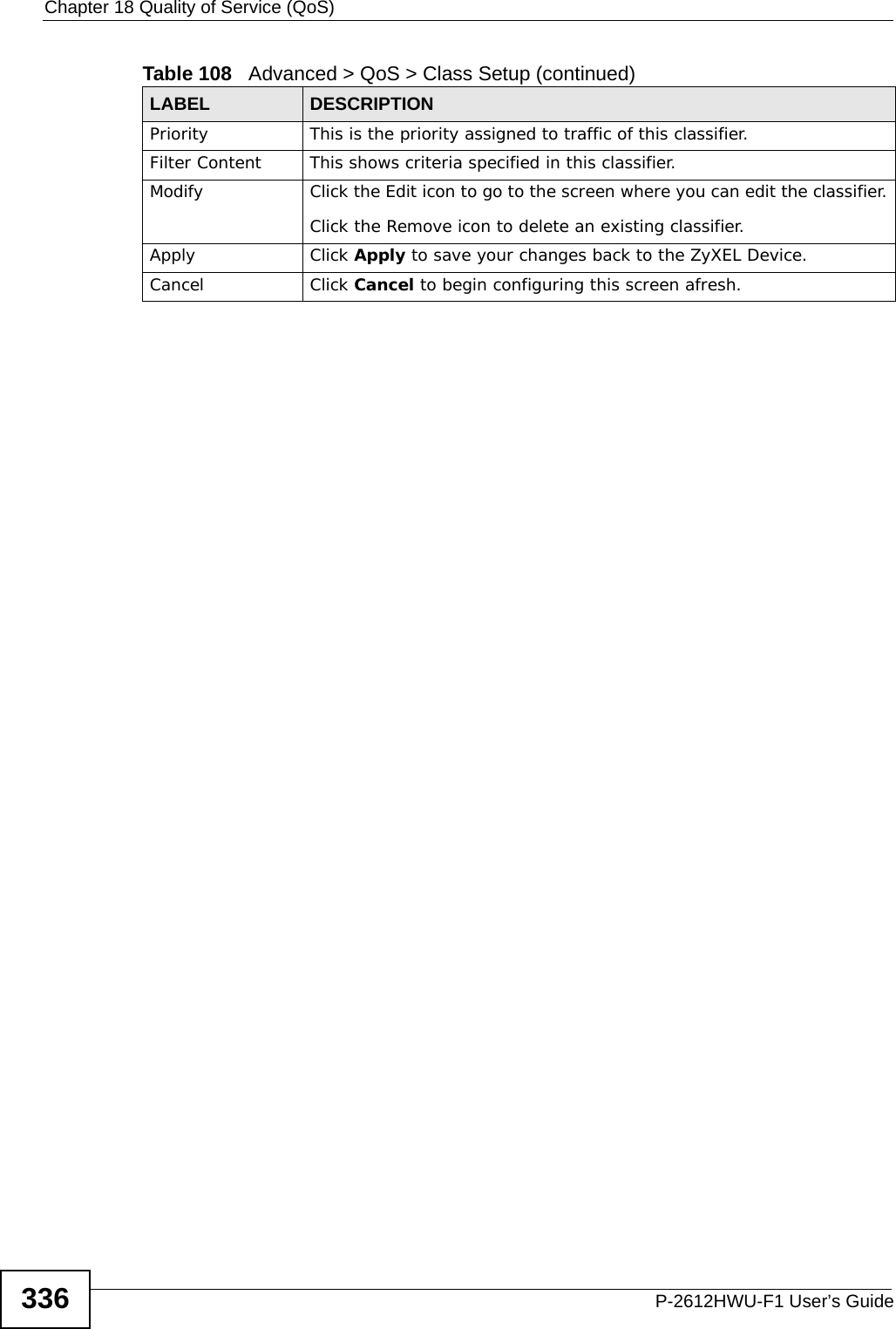
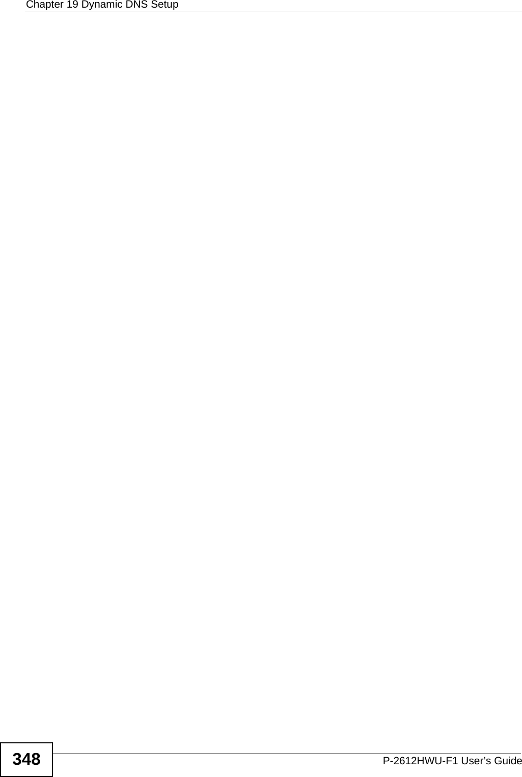
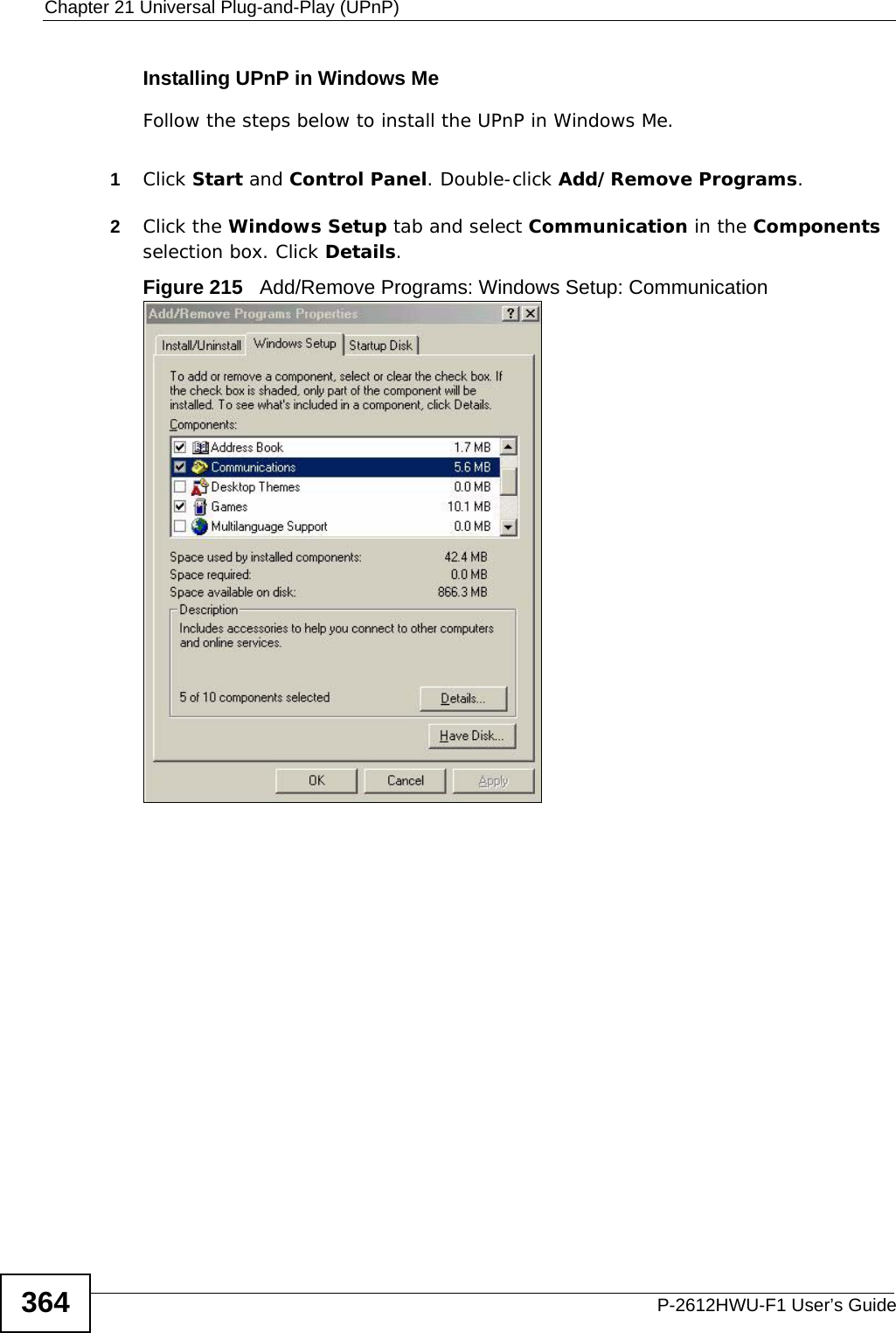
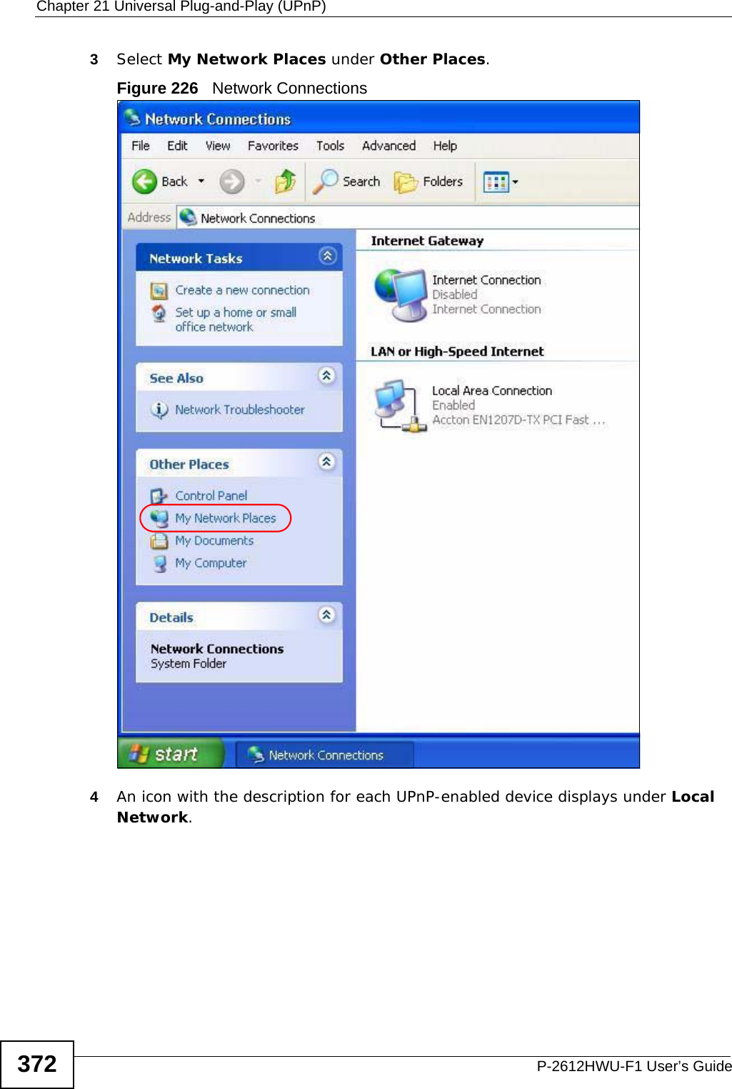
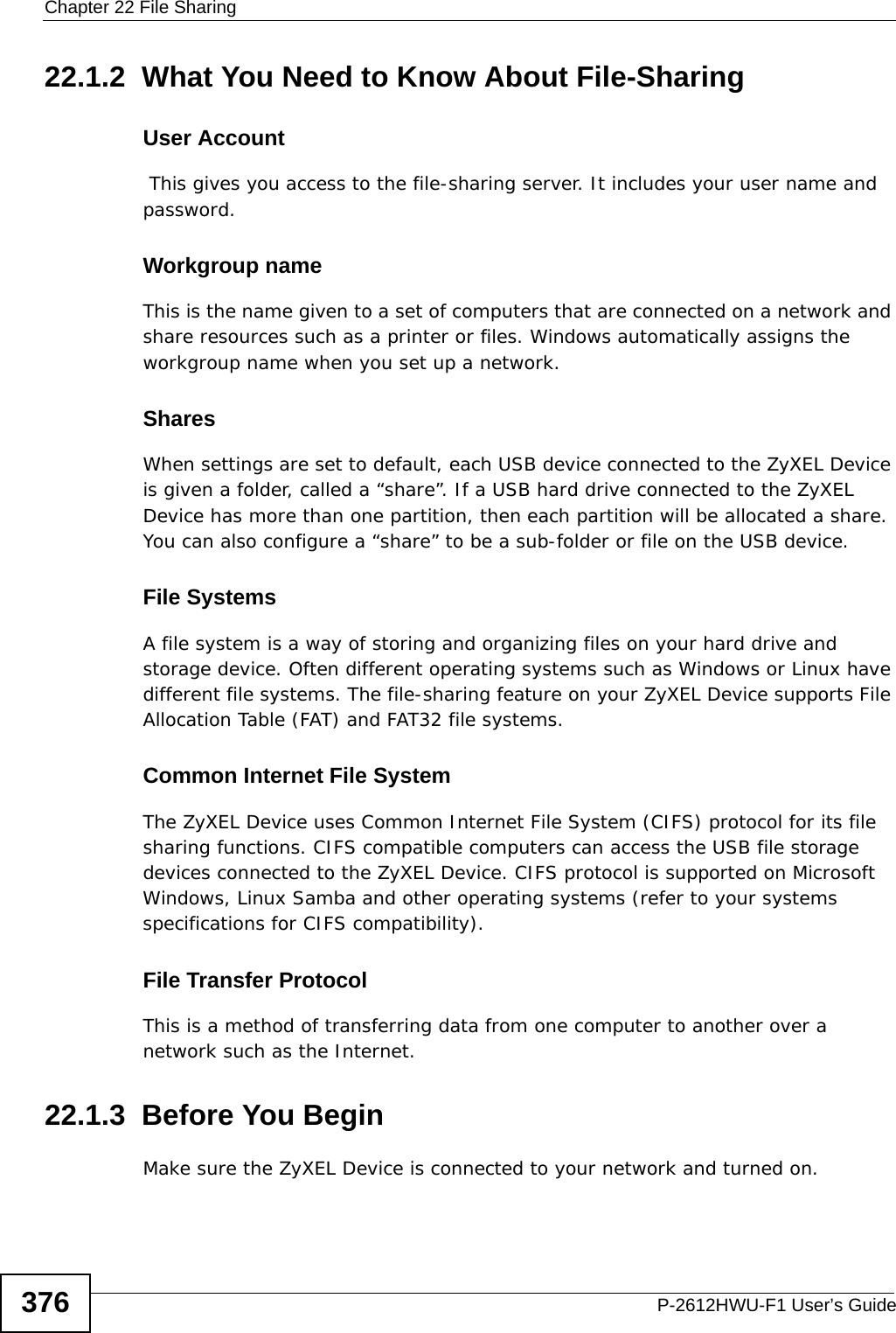
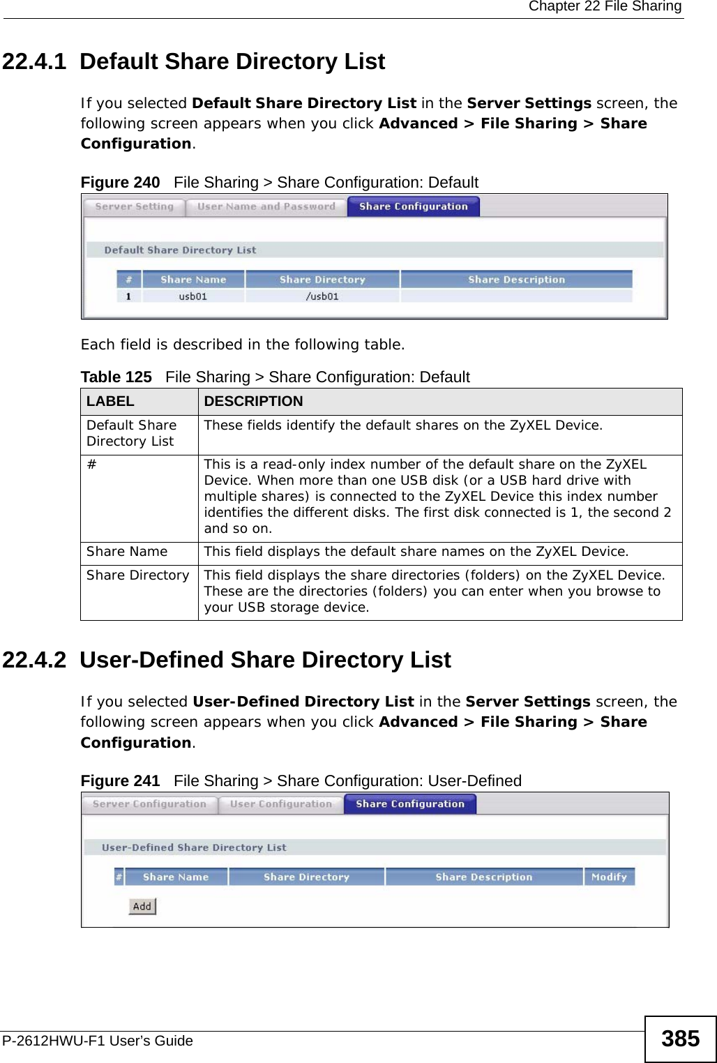
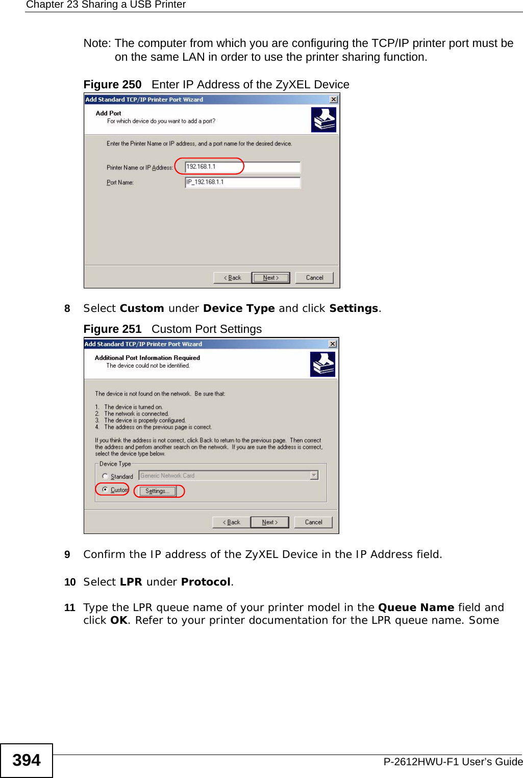
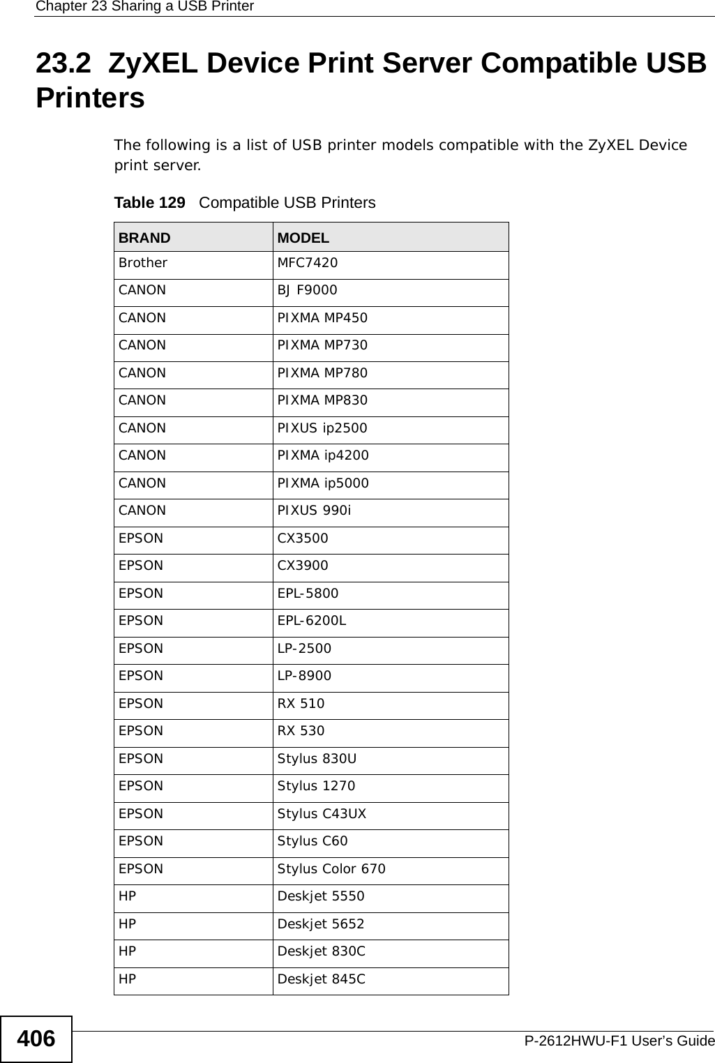
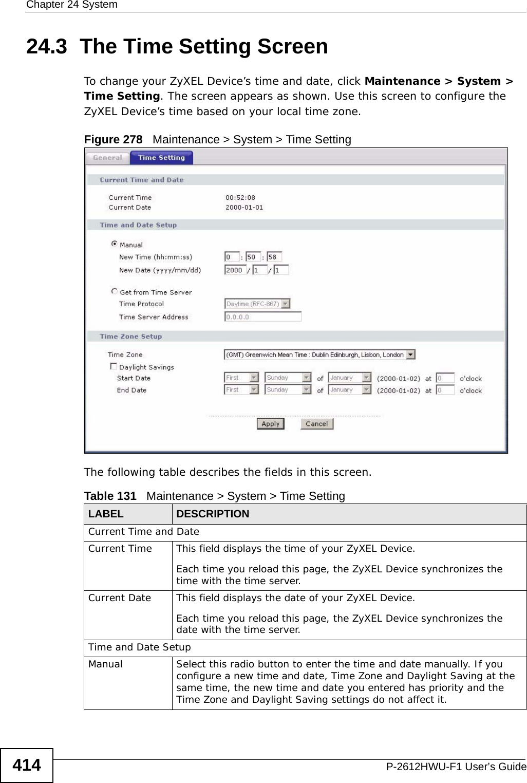
![Chapter 22 File SharingP-2612HWU-F1 User’s Guide 3811In Windows Explorer’s Address bar type a double backslash “\\” followed by the IP address of the ZyXEL Device (the default IP address of the ZyXEL Device is 192.168.1.1) and press [ENTER]. A screen asking for password authentication appears. Type the user name and password and click OK. Figure 236 File Sharing via Windows ExplorerNote: Once you login to the file “Bob’s Share” via your ZyXEL Device, you do not have to relogin unless you restart your computer. 22.2 The Server Settings ScreenIn the Server Settings screen you need to configure your ZyXEL Device’s Workgroup Name. The ZyXEL Device will not be able to join the workgroup if your local area network has restrictions set up that do not allow devices to join a workgroup. In this case, contact your network administrator.](https://usermanual.wiki/ZyXEL-Communications/P2612HWUFX.manual-part-3/User-Guide-1154264-Page-81.png)

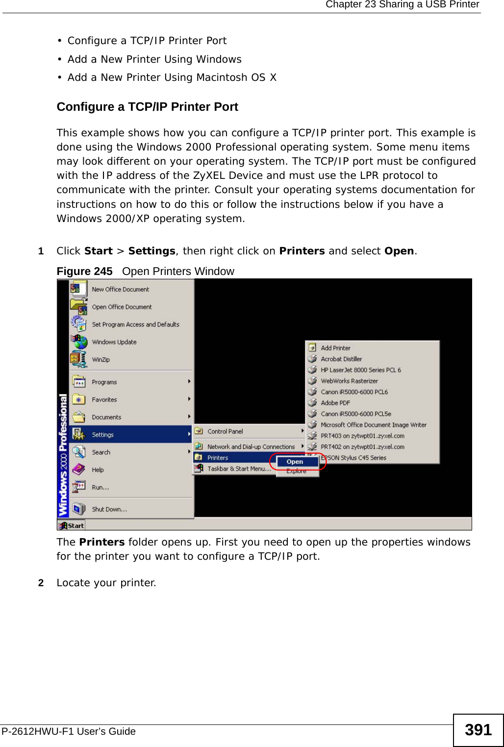
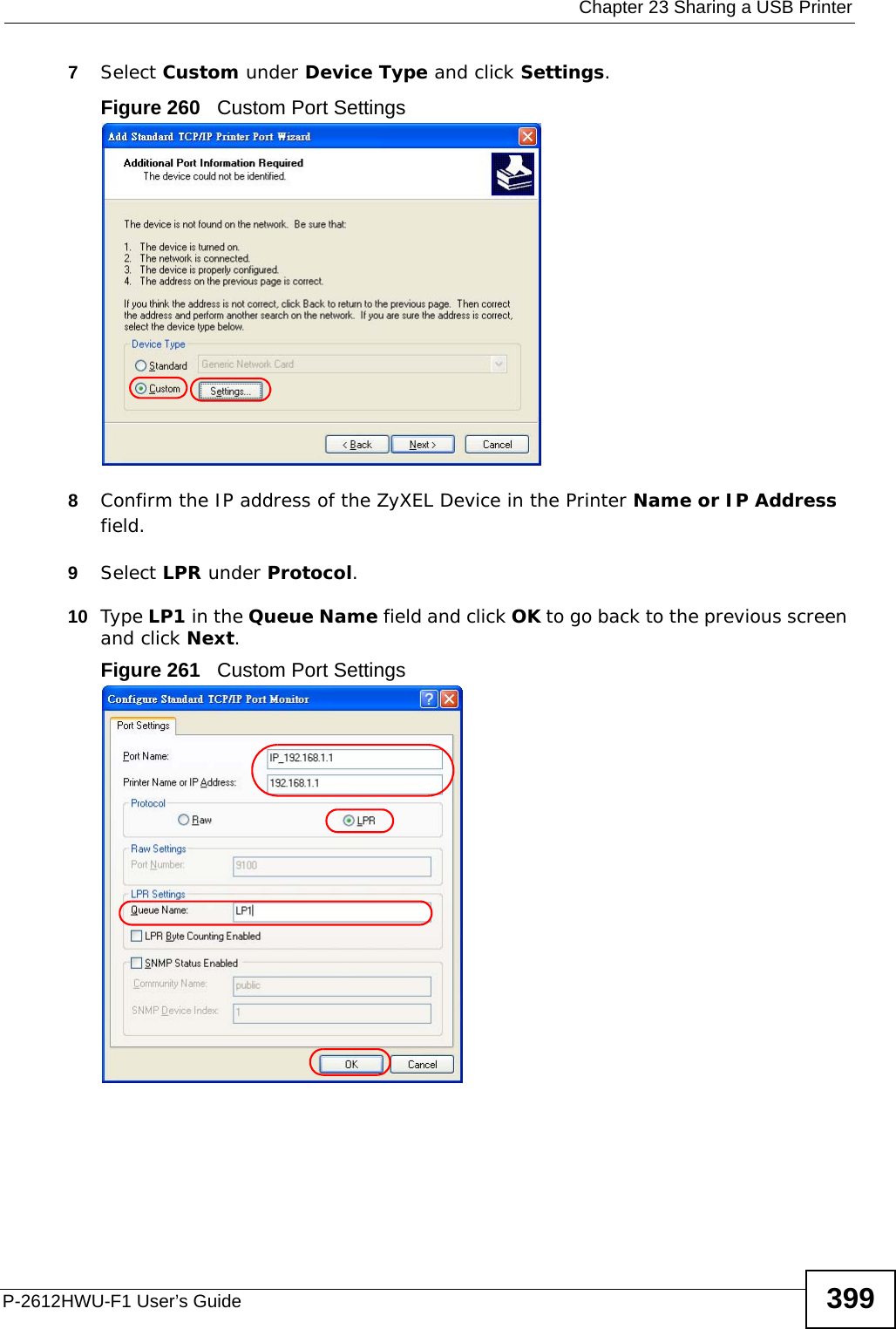
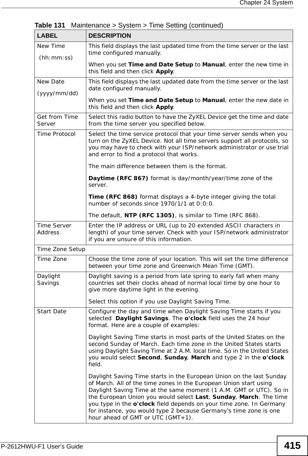
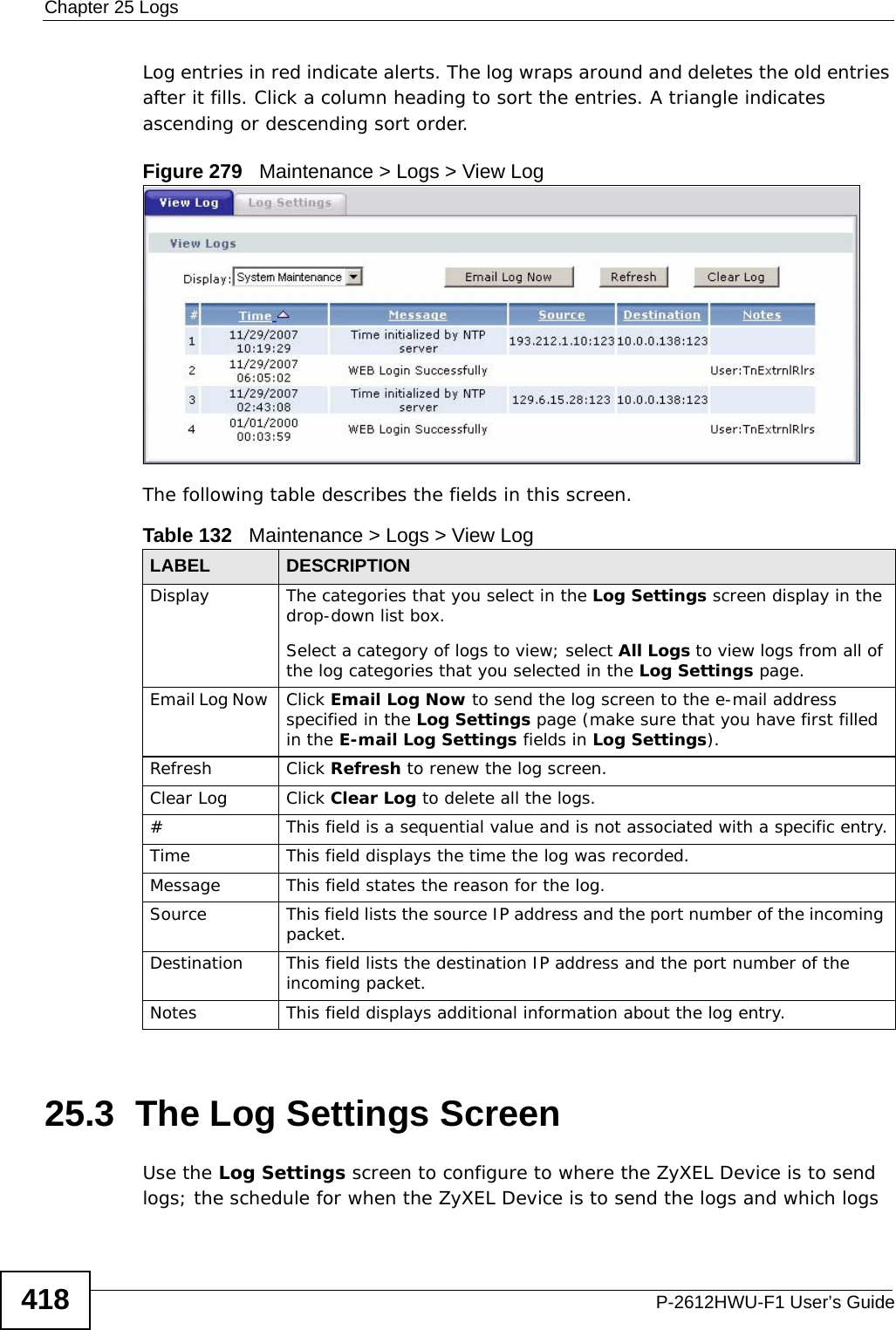
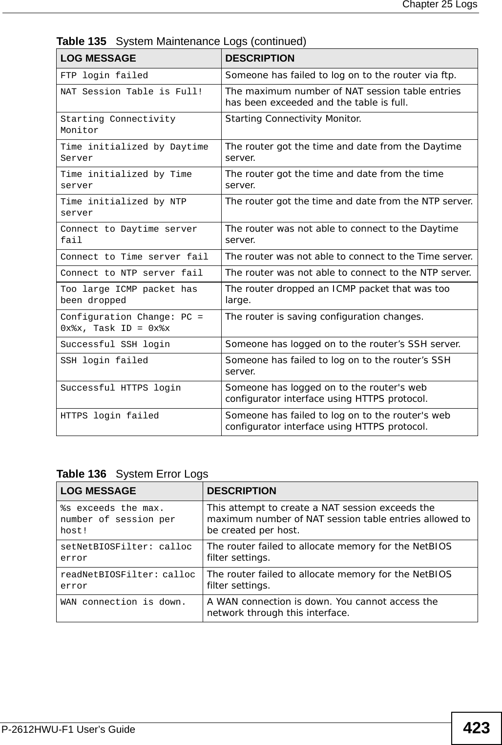
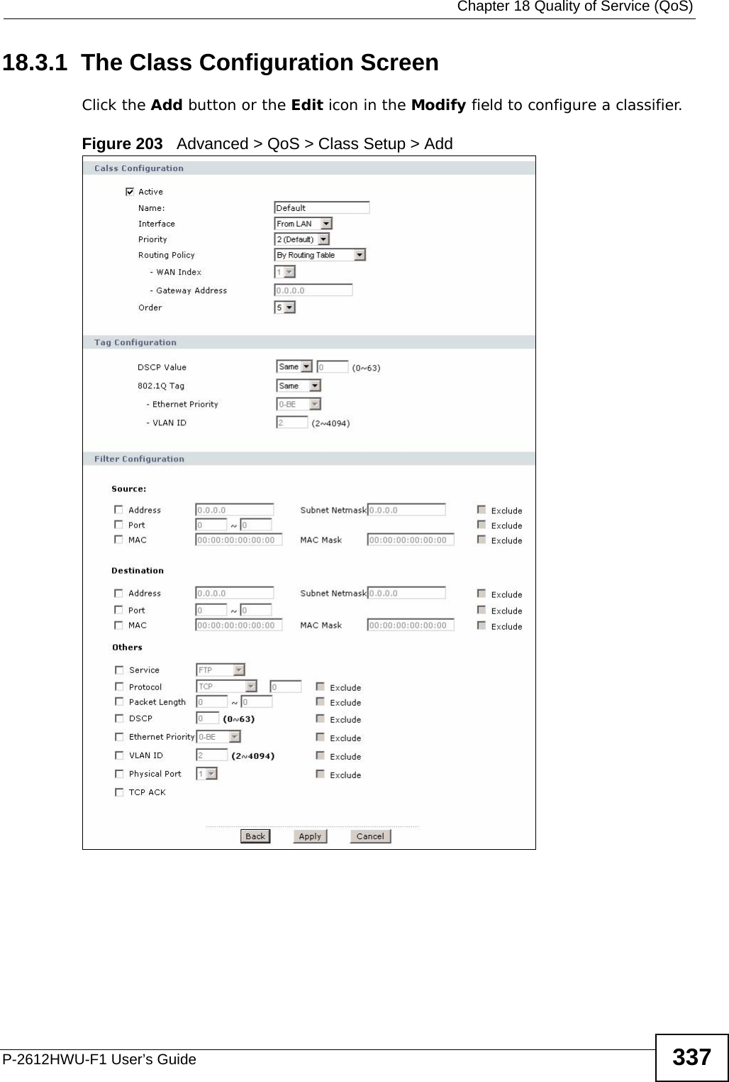
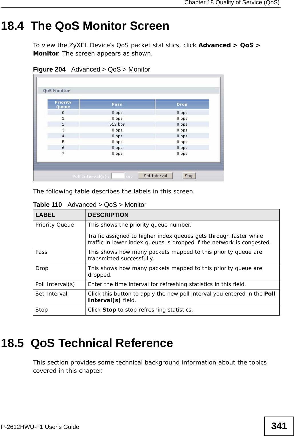
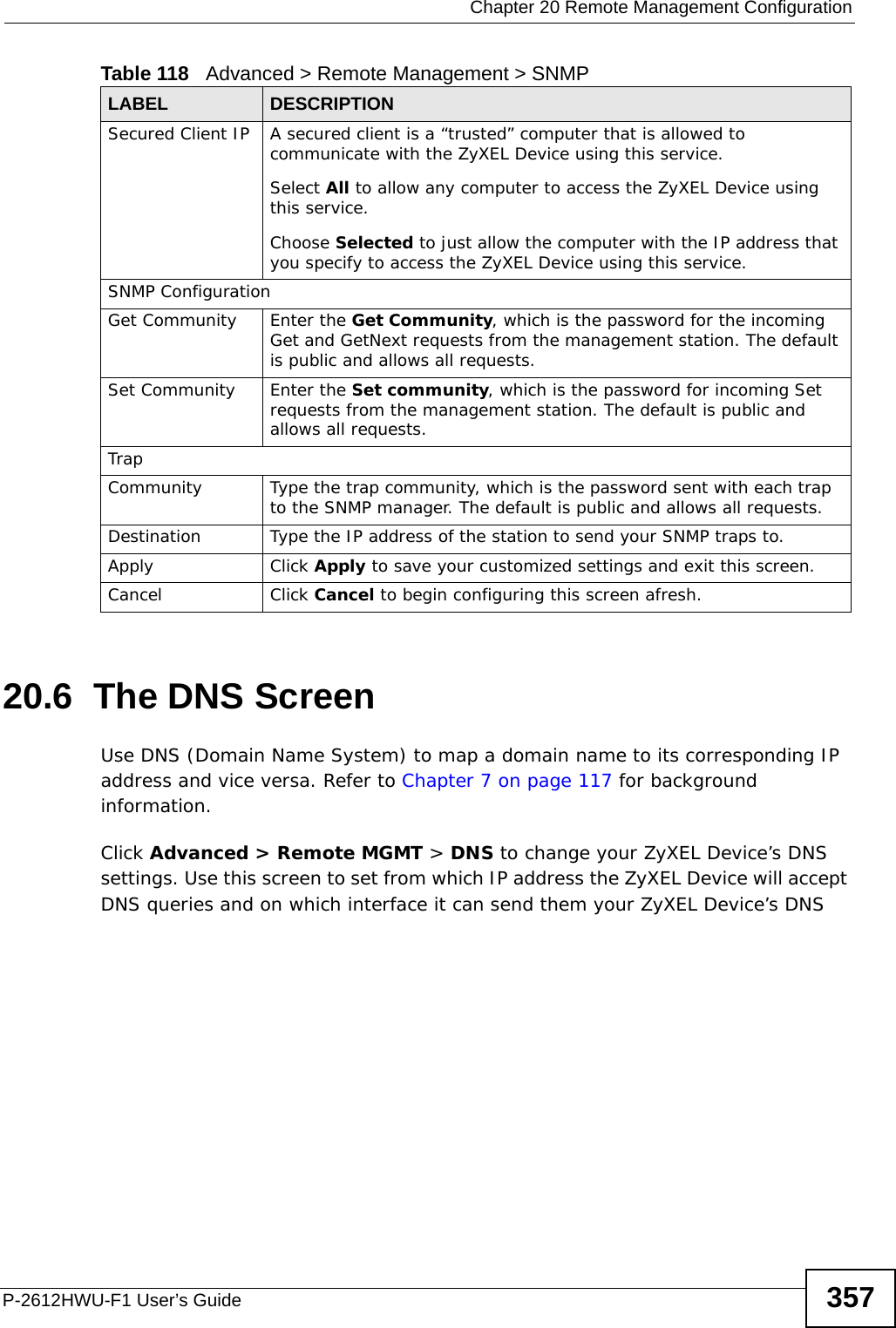
![Chapter 25 LogsP-2612HWU-F1 User’s Guide424 Table 137 Access Control LogsLOG MESSAGE DESCRIPTIONFirewall default policy: [ TCP | UDP | IGMP | ESP | GRE | OSPF ] <Packet Direction>Attempted TCP/UDP/IGMP/ESP/GRE/OSPF access matched the default policy and was blocked or forwarded according to the default policy’s setting.Firewall rule [NOT] match:[ TCP | UDP | IGMP | ESP | GRE | OSPF ] <Packet Direction>, <rule:%d>Attempted TCP/UDP/IGMP/ESP/GRE/OSPF access matched (or did not match) a configured firewall rule (denoted by its number) and was blocked or forwarded according to the rule. Triangle route packet forwarded: [ TCP | UDP | IGMP | ESP | GRE | OSPF ]The firewall allowed a triangle route session to pass through.Packet without a NAT table entry blocked: [ TCP | UDP | IGMP | ESP | GRE | OSPF ]The router blocked a packet that didn't have a corresponding NAT table entry.Router sent blocked web site message: TCP The router sent a message to notify a user that the router blocked access to a web site that the user requested.Table 138 TCP Reset LogsLOG MESSAGE DESCRIPTIONUnder SYN flood attack, sent TCP RST The router sent a TCP reset packet when a host was under a SYN flood attack (the TCP incomplete count is per destination host.) Exceed TCP MAX incomplete, sent TCP RST The router sent a TCP reset packet when the number of TCP incomplete connections exceeded the user configured threshold. (the TCP incomplete count is per destination host.) Note: Refer to TCP Maximum Incomplete in the Firewall Attack Alerts screen. Peer TCP state out of order, sent TCP RST The router sent a TCP reset packet when a TCP connection state was out of order.Note: The firewall refers to RFC793 Figure 6 to check the TCP state.Firewall session time out, sent TCP RST The router sent a TCP reset packet when a dynamic firewall session timed out.Default timeout values:ICMP idle timeout (s): 60UDP idle timeout (s): 60TCP connection (three way handshaking) timeout (s): 30TCP FIN-wait timeout (s): 60TCP idle (established) timeout (s): 3600](https://usermanual.wiki/ZyXEL-Communications/P2612HWUFX.manual-part-3/User-Guide-1154264-Page-124.png)
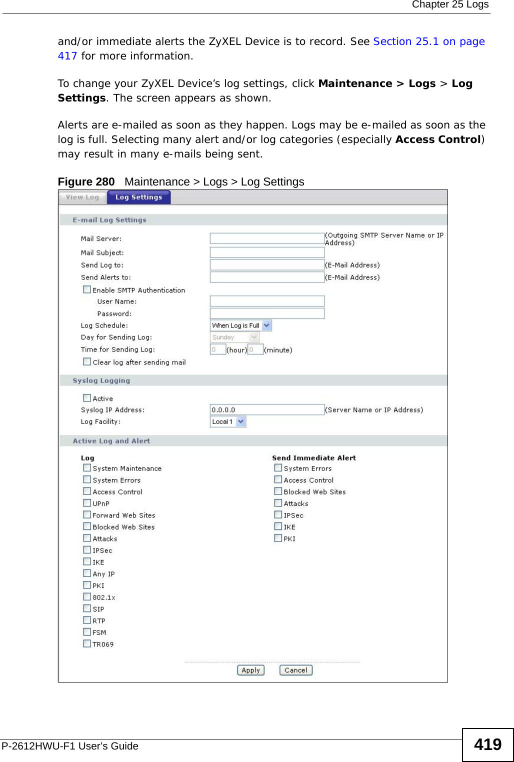
![Chapter 25 LogsP-2612HWU-F1 User’s Guide 425 For type and code details, see Table 148 on page 428.Exceed MAX incomplete, sent TCP RST The router sent a TCP reset packet when the number of incomplete connections (TCP and UDP) exceeded the user-configured threshold. (Incomplete count is for all TCP and UDP connections through the firewall.)Note: When the number of incomplete connections (TCP + UDP) > “Maximum Incomplete High”, the router sends TCP RST packets for TCP connections and destroys TOS (firewall dynamic sessions) until incomplete connections < “Maximum Incomplete Low”.Access block, sent TCP RST The router sends a TCP RST packet and generates this log if you turn on the firewall TCP reset mechanism (via CI command: "sys firewall tcprst").Table 139 Packet Filter LogsLOG MESSAGE DESCRIPTION[ TCP | UDP | ICMP | IGMP | Generic ] packet filter matched (set: %d, rule: %d)Attempted access matched a configured filter rule (denoted by its set and rule number) and was blocked or forwarded according to the rule.Table 140 ICMP LogsLOG MESSAGE DESCRIPTIONFirewall default policy: ICMP <Packet Direction>, <type:%d>, <code:%d>ICMP access matched the default policy and was blocked or forwarded according to the user's setting.Firewall rule [NOT] match: ICMP <Packet Direction>, <rule:%d>, <type:%d>, <code:%d>ICMP access matched (or didn’t match) a firewall rule (denoted by its number) and was blocked or forwarded according to the rule. Triangle route packet forwarded: ICMP The firewall allowed a triangle route session to pass through.Packet without a NAT table entry blocked: ICMP The router blocked a packet that didn’t have a corresponding NAT table entry.Unsupported/out-of-order ICMP: ICMP The firewall does not support this kind of ICMP packets or the ICMP packets are out of order.Router reply ICMP packet: ICMP The router sent an ICMP reply packet to the sender.Table 138 TCP Reset Logs (continued)LOG MESSAGE DESCRIPTION](https://usermanual.wiki/ZyXEL-Communications/P2612HWUFX.manual-part-3/User-Guide-1154264-Page-125.png)
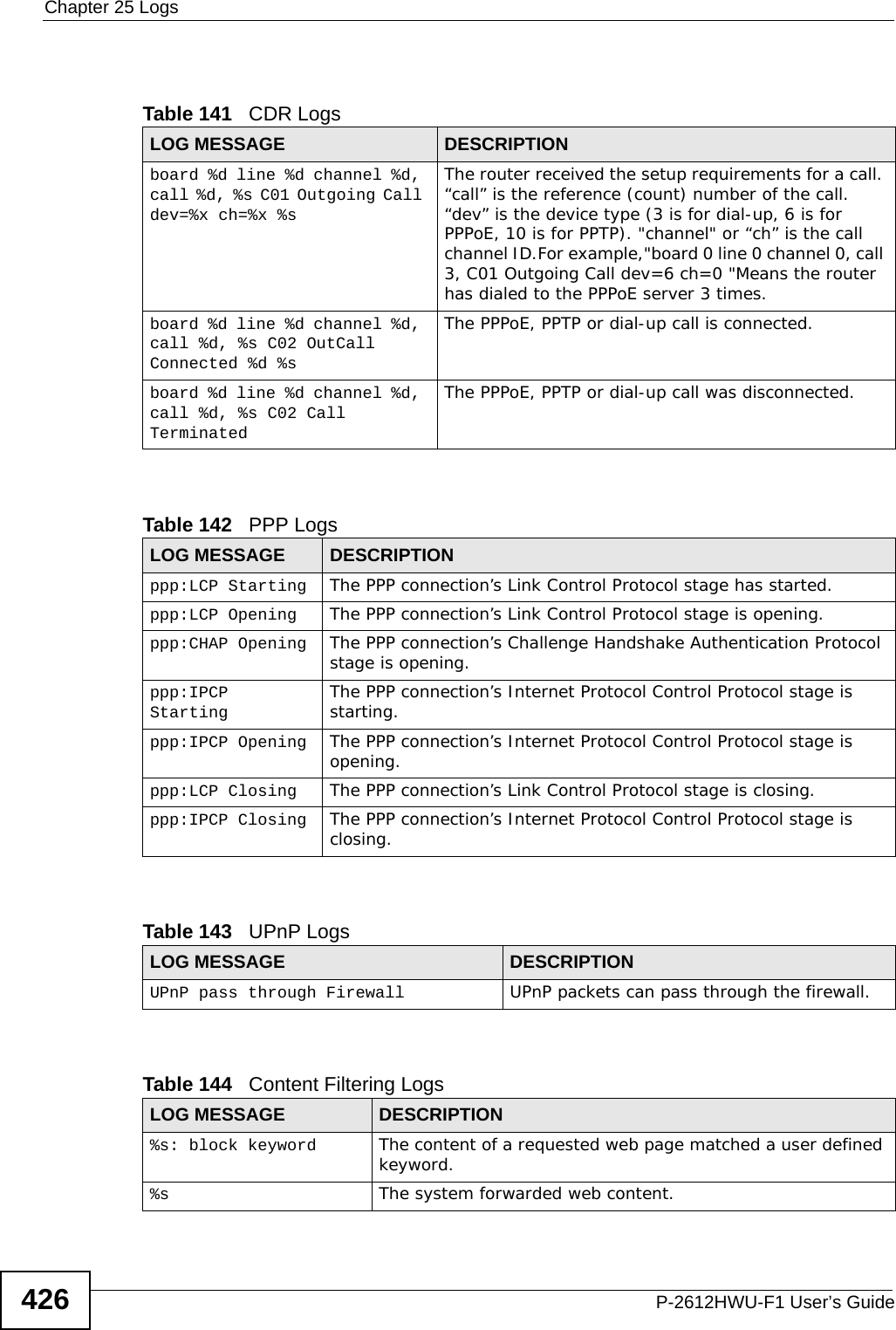
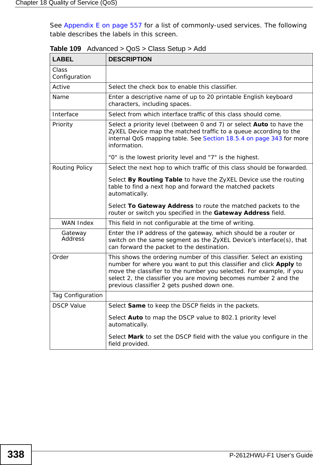
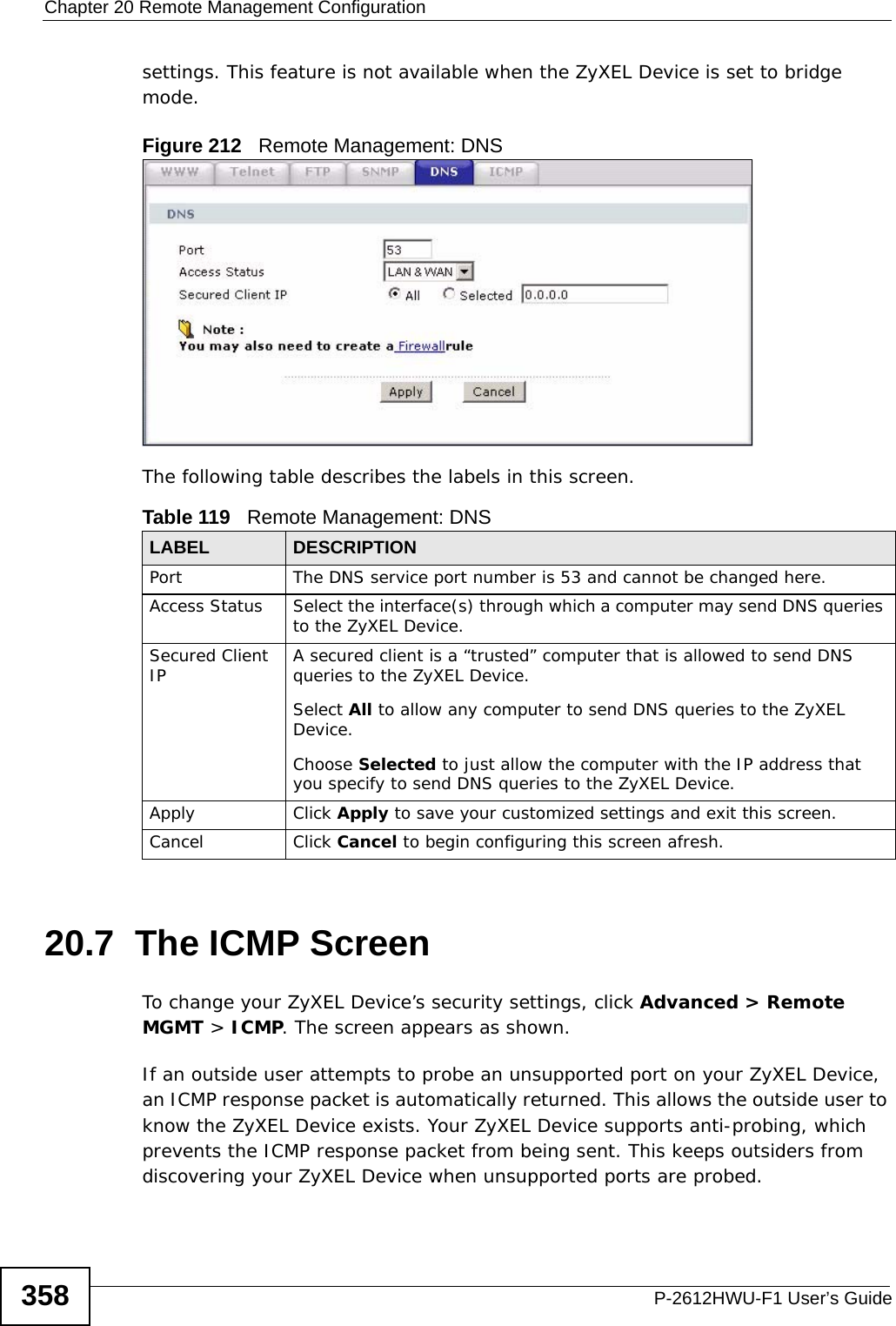
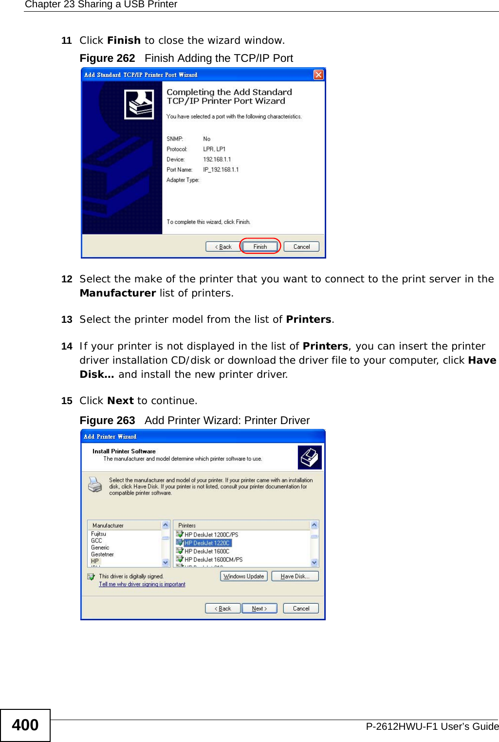
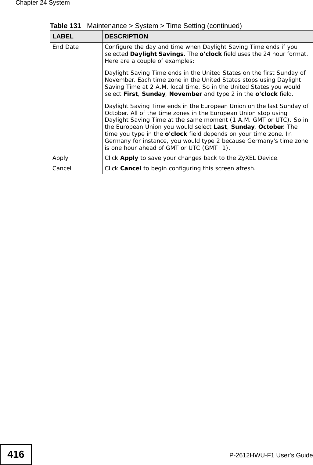
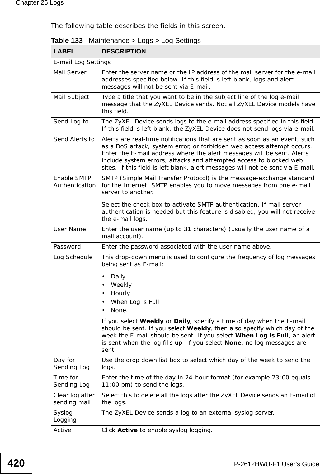
![Chapter 25 LogsP-2612HWU-F1 User’s Guide 427For type and code details, see Table 148 on page 428. Table 145 Attack LogsLOG MESSAGE DESCRIPTIONattack [ TCP | UDP | IGMP | ESP | GRE | OSPF ] The firewall detected a TCP/UDP/IGMP/ESP/GRE/OSPF attack.attack ICMP (type:%d, code:%d) The firewall detected an ICMP attack.land [ TCP | UDP | IGMP | ESP | GRE | OSPF ] The firewall detected a TCP/UDP/IGMP/ESP/GRE/OSPF land attack.land ICMP (type:%d, code:%d) The firewall detected an ICMP land attack.ip spoofing - WAN [ TCP | UDP | IGMP | ESP | GRE | OSPF ]The firewall detected an IP spoofing attack on the WAN port.ip spoofing - WAN ICMP (type:%d, code:%d) The firewall detected an ICMP IP spoofing attack on the WAN port. icmp echo : ICMP (type:%d, code:%d) The firewall detected an ICMP echo attack. syn flood TCP The firewall detected a TCP syn flood attack.ports scan TCP The firewall detected a TCP port scan attack.teardrop TCP The firewall detected a TCP teardrop attack.teardrop UDP The firewall detected an UDP teardrop attack.teardrop ICMP (type:%d, code:%d) The firewall detected an ICMP teardrop attack. illegal command TCP The firewall detected a TCP illegal command attack.NetBIOS TCP The firewall detected a TCP NetBIOS attack.ip spoofing - no routing entry [ TCP | UDP | IGMP | ESP | GRE | OSPF ]The firewall classified a packet with no source routing entry as an IP spoofing attack.ip spoofing - no routing entry ICMP (type:%d, code:%d)The firewall classified an ICMP packet with no source routing entry as an IP spoofing attack.vulnerability ICMP (type:%d, code:%d) The firewall detected an ICMP vulnerability attack.traceroute ICMP (type:%d, code:%d) The firewall detected an ICMP traceroute attack. Table 146 802.1X LogsLOG MESSAGE DESCRIPTIONRADIUS accepts user. A user was authenticated by the RADIUS Server.RADIUS rejects user. Pls check RADIUS Server. A user was not authenticated by the RADIUS Server. Please check the RADIUS Server.User logout because of session timeout expired. The router logged out a user whose session expired.](https://usermanual.wiki/ZyXEL-Communications/P2612HWUFX.manual-part-3/User-Guide-1154264-Page-127.png)
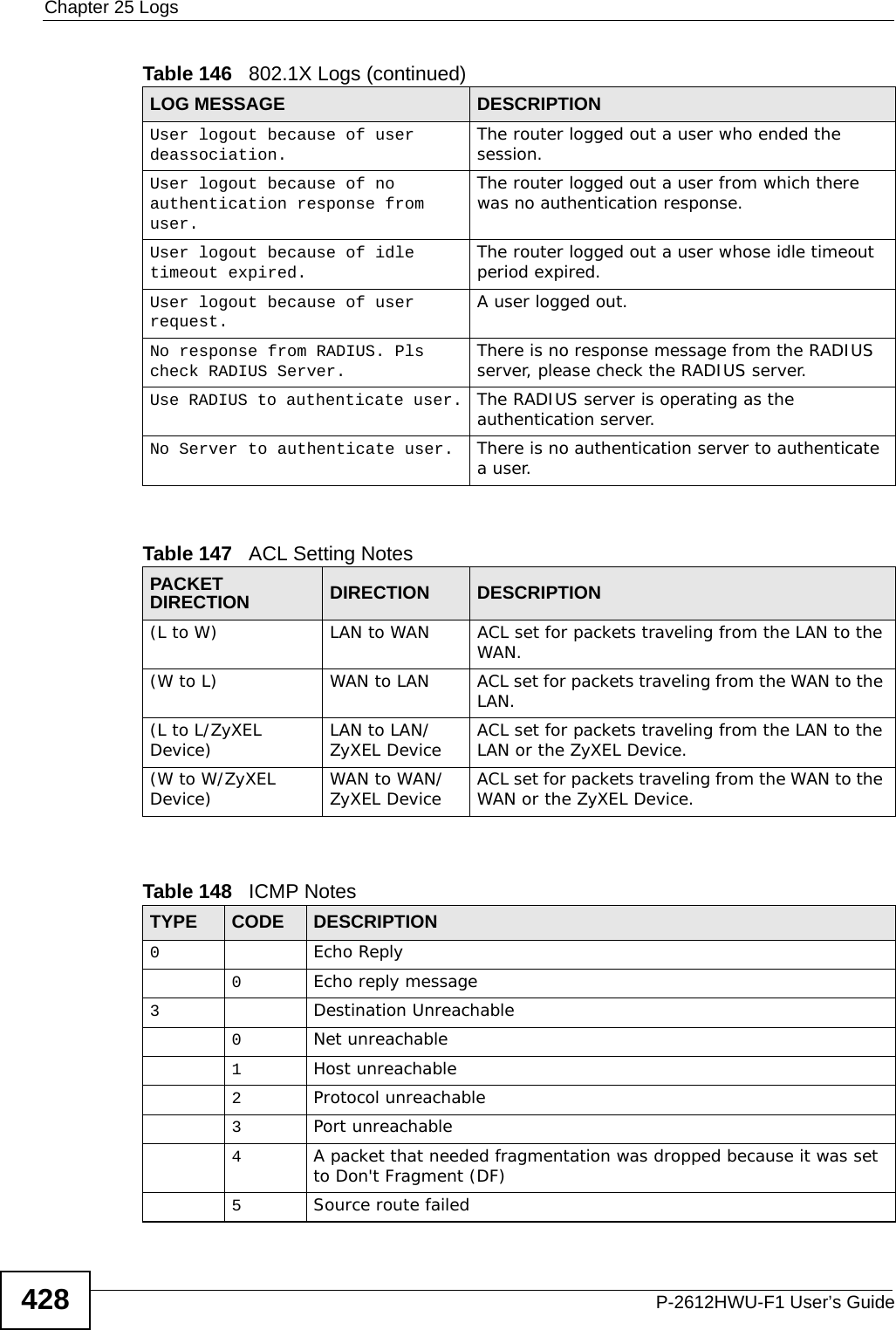
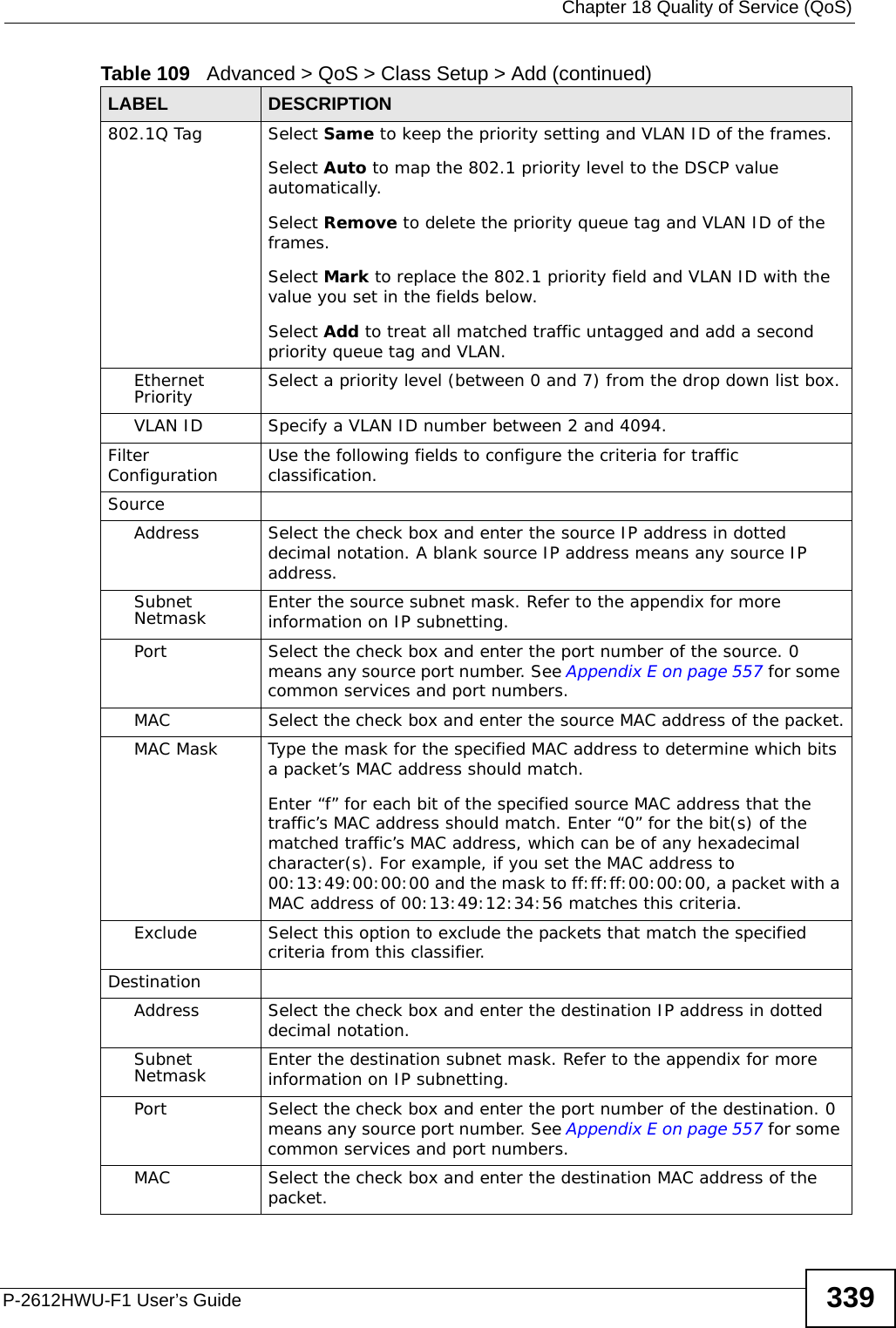
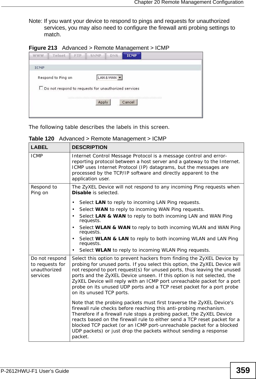
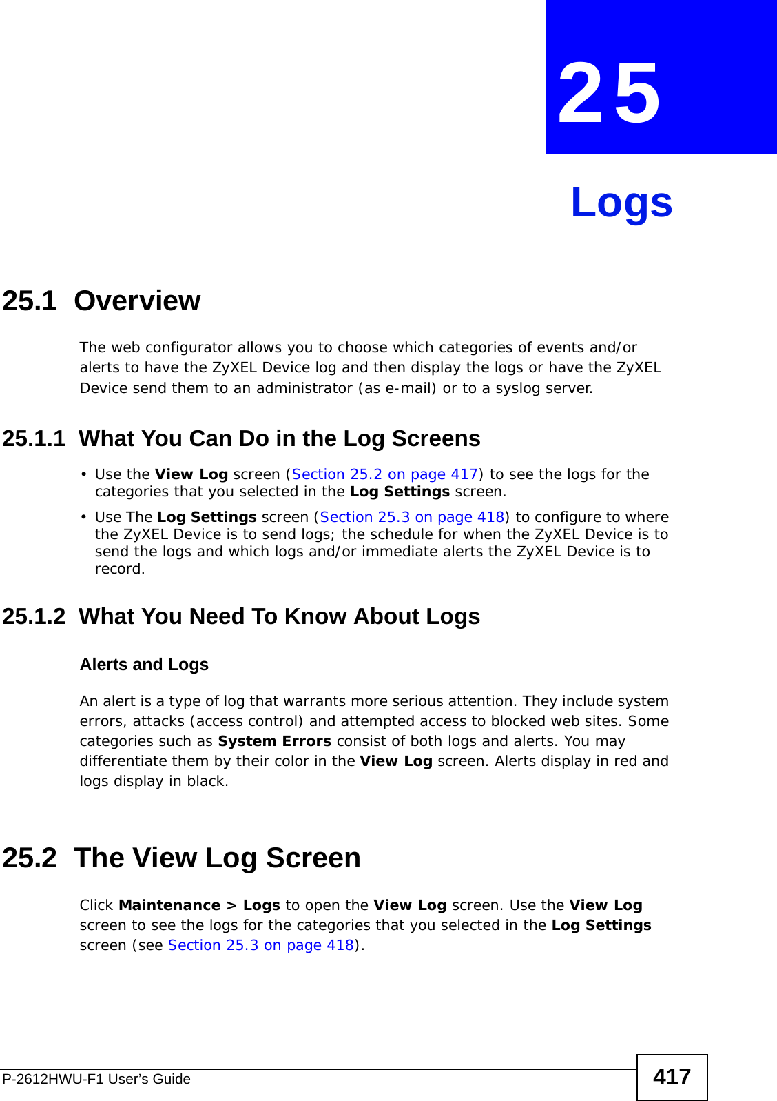
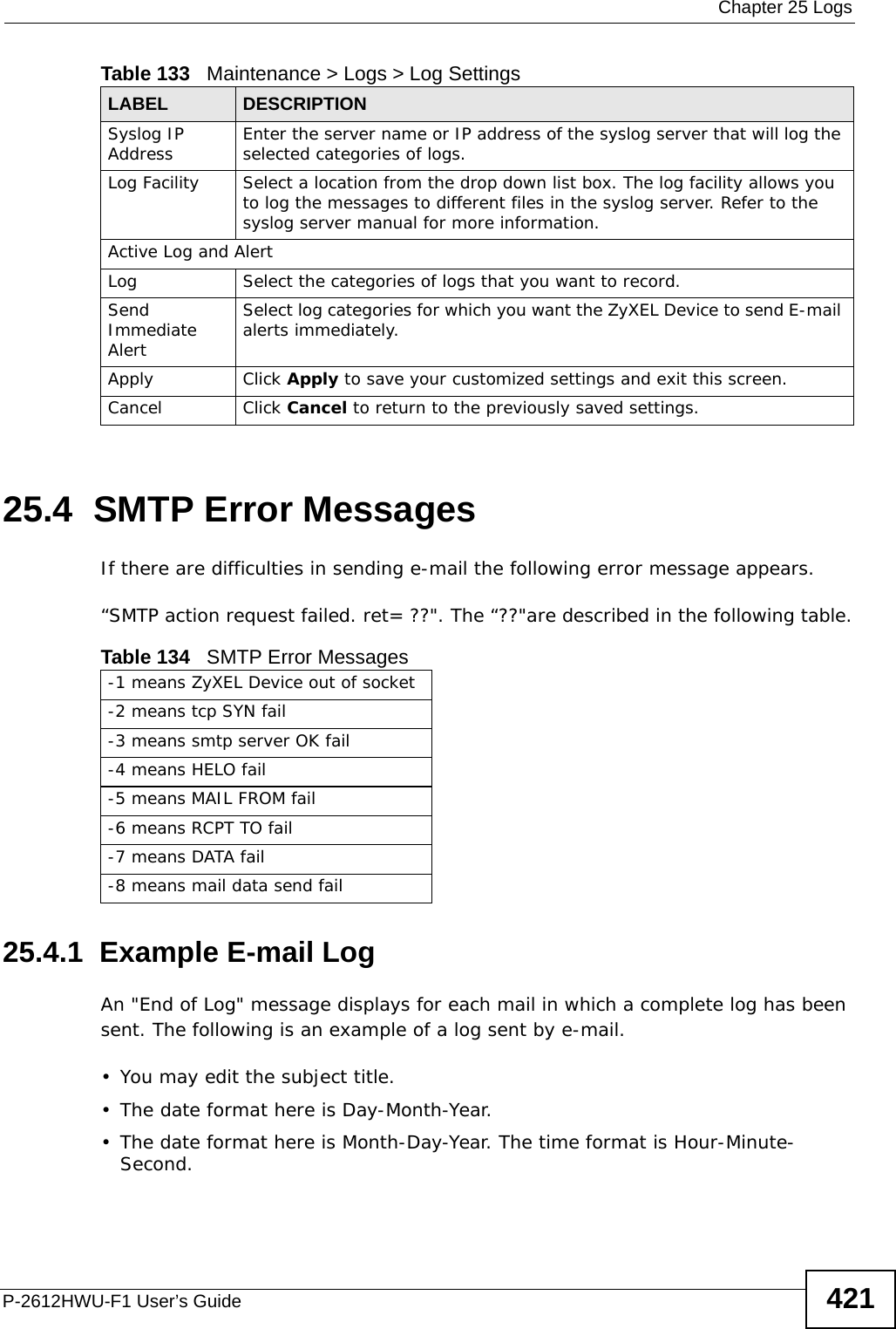
![Chapter 25 LogsP-2612HWU-F1 User’s Guide430Table 150 SIP LogsLOG MESSAGE DESCRIPTIONSIP Registration Success by SIP:SIP Phone Number The listed SIP account was successfully registered with a SIP register server.SIP Registration Fail by SIP:SIP Phone Number An attempt to register the listed SIP account with a SIP register server was not successful.SIP UnRegistration Success by SIP:SIP Phone NumberThe listed SIP account’s registration was deleted from the SIP register server.SIP UnRegistration Fail by SIP:SIP Phone Number An attempt to delete the listed SIP account’s registration from the SIP register server failed.Table 151 RTP LogsLOG MESSAGE DESCRIPTIONError, RTP init fail The initialization of an RTP session failed.Error, Call fail: RTP connect fail A VoIP phone call failed because the RTP session could not be established.Error, RTP connection cannot close The termination of an RTP session failed.Table 152 FSM Logs: Caller SideLOG MESSAGE DESCRIPTIONVoIP Call Start Ph[Phone Port Number] <- Outgoing Call NumberSomeone used a phone connected to the listed phone port to initiate a VoIP call to the listed destination.VoIP Call Established Ph[Phone Port] -> Outgoing Call NumberSomeone used a phone connected to the listed phone port to make a VoIP call to the listed destination.VoIP Call End Phone[Phone Port] A VoIP phone call made from a phone connected to the listed phone port has terminated.](https://usermanual.wiki/ZyXEL-Communications/P2612HWUFX.manual-part-3/User-Guide-1154264-Page-130.png)
![Chapter 25 LogsP-2612HWU-F1 User’s Guide 431The following table shows RFC-2408 ISAKMP payload types that the log displays. Please refer to RFC 2408 for detailed information on each type. Table 153 FSM Logs: Callee SideLOG MESSAGE DESCRIPTIONVoIP Call Start from SIP[SIP Port Number] A VoIP phone call came to the ZyXEL Device from the listed SIP number.VoIP Call Established Ph[Phone Port] <- Outgoing Call NumberA VoIP phone call was set up from the listed SIP number to the ZyXEL Device.VoIP Call End Phone[Phone Port] A VoIP phone call that came into the ZyXEL Device has terminated.Table 154 RFC-2408 ISAKMP Payload TypesLOG DISPLAY PAYLOAD TYPESA Security AssociationPROP ProposalTRANS TransformKE Key ExchangeID IdentificationCER CertificateCER_REQ Certificate RequestHASH HashSIG SignatureNONCE NonceNOTFY NotificationDEL DeleteVID Vendor ID](https://usermanual.wiki/ZyXEL-Communications/P2612HWUFX.manual-part-3/User-Guide-1154264-Page-131.png)

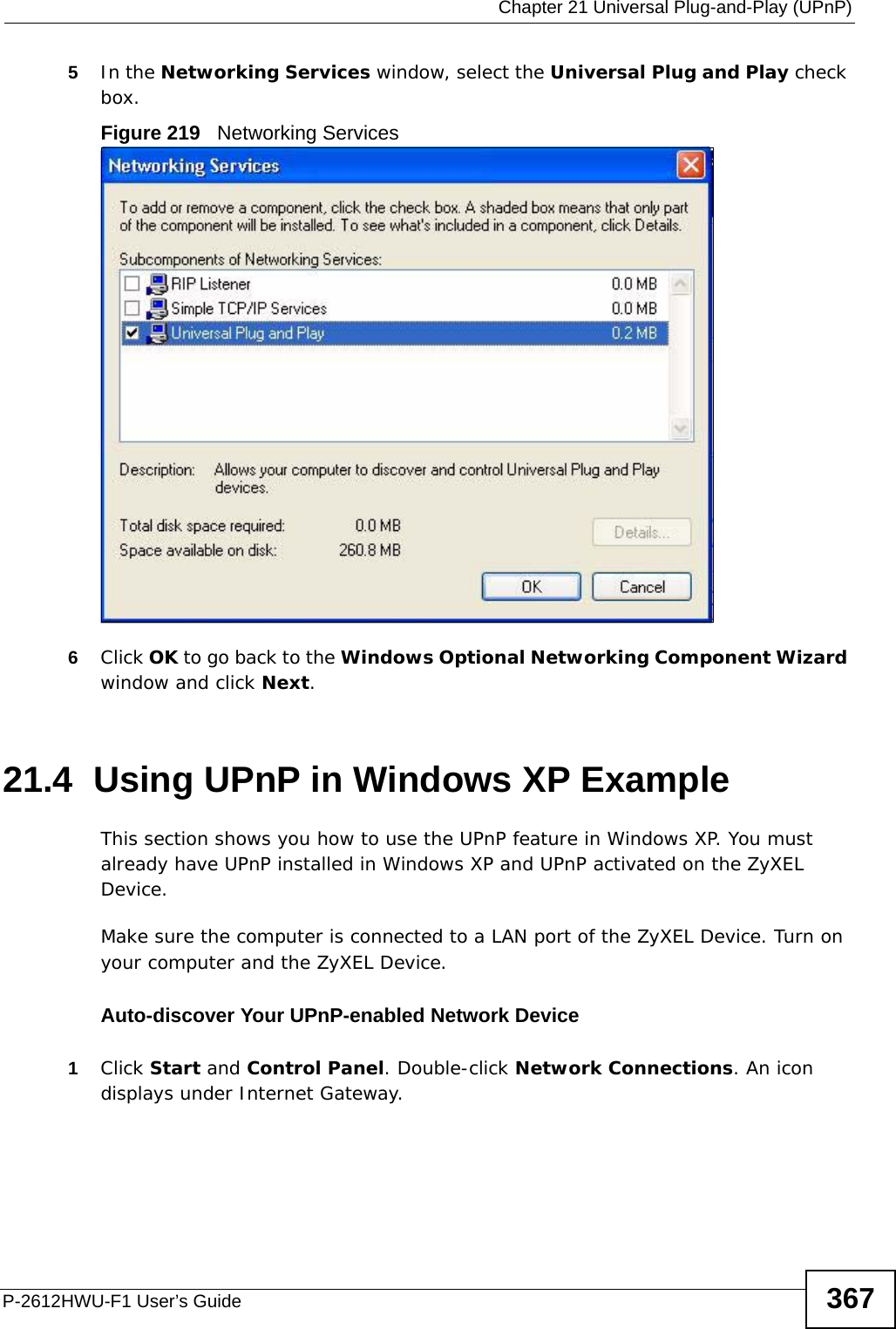
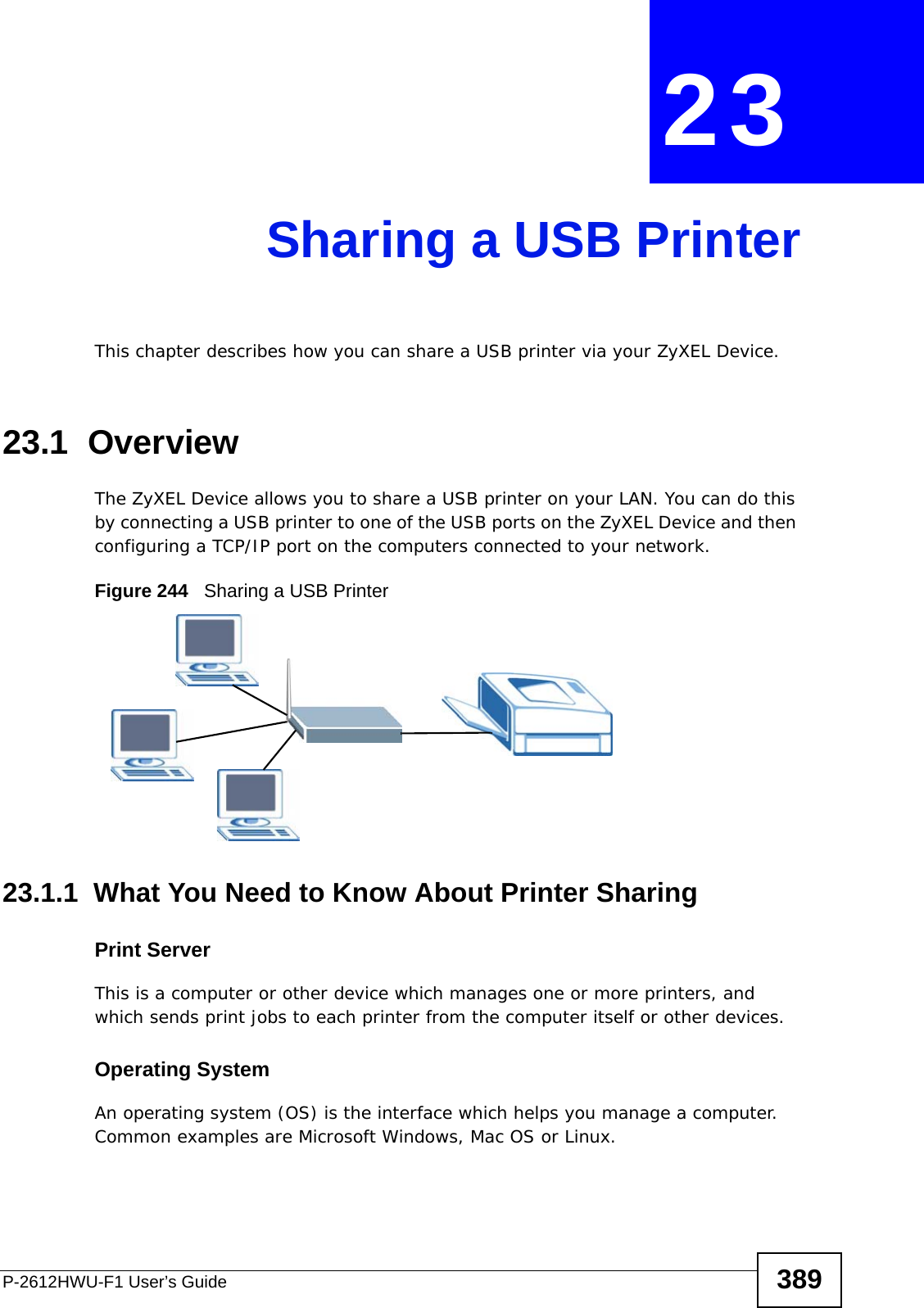
![Chapter 27 ToolsP-2612HWU-F1 User’s Guide442FTP and TFTP Firmware and Configuration File UploadsThese examples show you how to upload firmware and configuration files. Do not interrupt the file transfer process as this may PERMANENTLY DAMAGE your device. FTP is the preferred method for uploading the firmware and configuration. To use this feature, your computer must have an FTP client. The following sections give examples of how to upload the firmware and the configuration files.FTP File Upload Command from the DOS Prompt Example1Launch the FTP client on your computer.2Enter “open”, followed by a space and the IP address of your device. 3Press [ENTER] when prompted for a username.4Enter your password as requested (the default is “1234”).5Enter “bin” to set transfer mode to binary.6Use “put” to transfer files from the computer to the device, for example, “put firmware.bin ras” transfers the firmware on your computer (firmware.bin) to the device and renames it “ras”. Similarly, “put config.rom rom-0” transfers the configuration file on your computer (config.rom) to the device and renames it “rom-0”. Likewise “get rom-0 config.rom” transfers the configuration file on the device to your computer and renames it “config.rom.” See earlier in this chapter for more information on filename conventions.7Enter “quit” to exit the ftp prompt.FTP Session Example of Firmware File UploadFigure 286 FTP Session Example of Firmware File Upload331 Enter PASS commandPassword:230 Logged inftp> bin200 Type I OKftp> put firmware.bin ras200 Port command okay150 Opening data connection for STOR ras226 File received OKftp: 1103936 bytes sent in 1.10Seconds 297.89Kbytes/sec.ftp> quit](https://usermanual.wiki/ZyXEL-Communications/P2612HWUFX.manual-part-3/User-Guide-1154264-Page-142.png)
![Chapter 27 ToolsP-2612HWU-F1 User’s Guide 443More commands (found in GUI-based FTP clients) are listed in this chapter.Refer to Section 27.1.2 on page 439 to read about configurations that disallow TFTP and FTP over WAN.TFTP File UploadThe device also supports the uploading of firmware files using TFTP (Trivial File Transfer Protocol) over LAN. Although TFTP should work over WAN as well, it is not recommended.To use TFTP, your computer must have both telnet and TFTP clients. To transfer the firmware and the configuration file, follow the procedure shown next.1Use telnet from your computer to connect to the device and log in. Because TFTP does not have any security checks, the device records the IP address of the telnet client and accepts TFTP requests only from this address.2Enter the command “sys stdio 0” to disable the management idle timeout, so the TFTP transfer will not be interrupted. Enter “command sys stdio 5” to restore the five-minute management idle timeout (default) when the file transfer is complete.3Launch the TFTP client on your computer and connect to the device. Set the transfer mode to binary before starting data transfer.4Use the TFTP client (see the example below) to transfer files between the device and the computer. The file name for the firmware is “ras”.Note that the telnet connection must be active and the device in CI mode before and during the TFTP transfer. For details on TFTP commands (see following example), please consult the documentation of your TFTP client program. For UNIX, use “get” to transfer from the device to the computer, “put” the other way around, and “binary” to set binary transfer mode.TFTP Upload Command ExampleThe following is an example TFTP command:tftp [-i] host put firmware.bin rasWhere “i” specifies binary image transfer mode (use this mode when transferring binary files), “host” is the device’s IP address, “put” transfers the file source on the computer (firmware.bin – name of the firmware on the computer) to the file destination on the remote host (ras - name of the firmware on the device).Commands that you may see in GUI-based TFTP clients are listed earlier in this chapter.](https://usermanual.wiki/ZyXEL-Communications/P2612HWUFX.manual-part-3/User-Guide-1154264-Page-143.png)
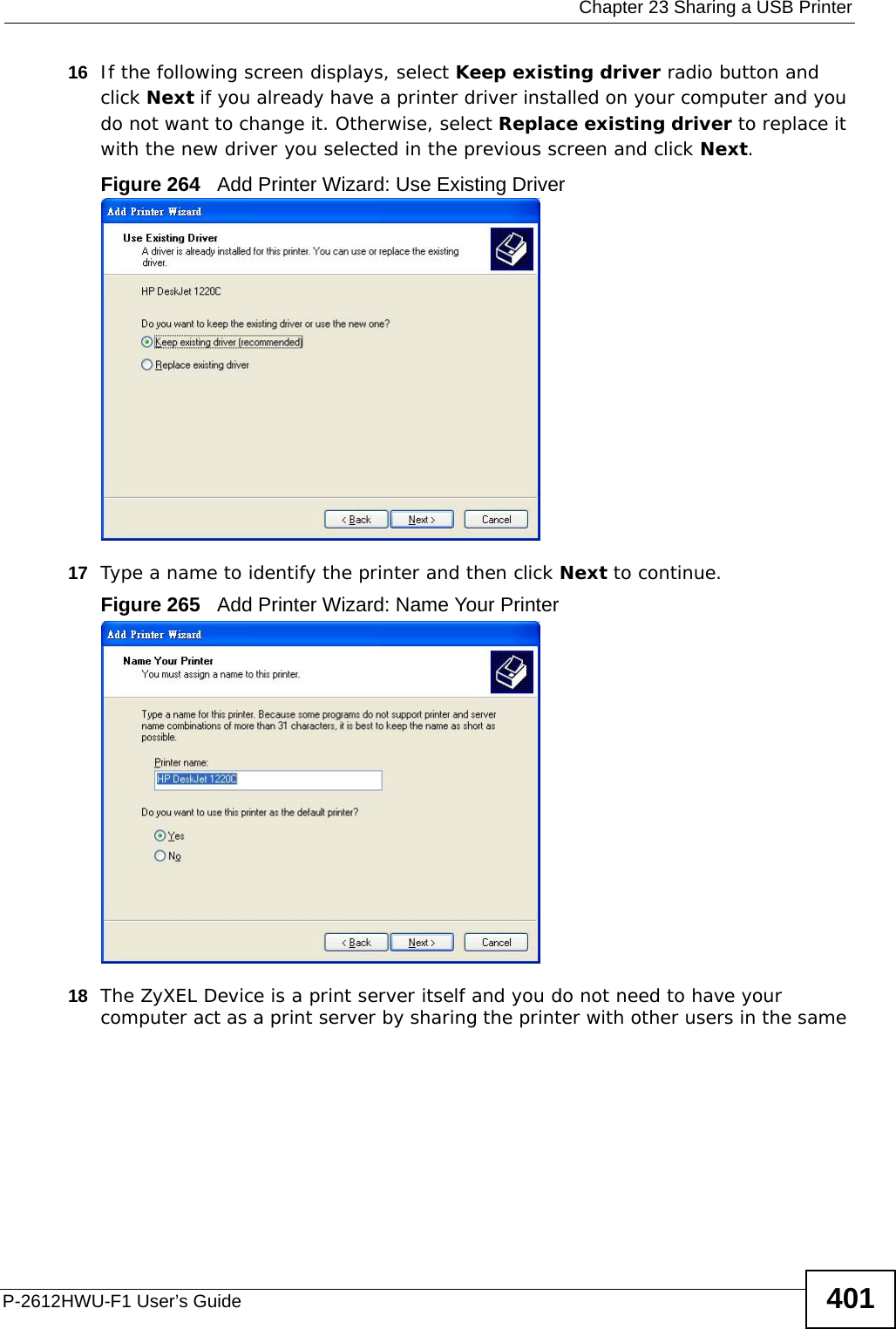
![Chapter 27 ToolsP-2612HWU-F1 User’s Guide444Using the FTP Commands to Back Up Configuration1Launch the FTP client on your computer.2Enter “open”, followed by a space and the IP address of your ZyXEL Device. 3Press [ENTER] when prompted for a username.4Enter your password as requested (the default is “1234”).5Enter “bin” to set transfer mode to binary.6Use “get” to transfer files from the ZyXEL Device to the computer, for example, “get rom-0 config.rom” transfers the configuration file on the ZyXEL Device to your computer and renames it “config.rom”. See earlier in this chapter for more information on filename conventions.7Enter “quit” to exit the ftp prompt. FTP Command Configuration Backup ExampleThis figure gives an example of using FTP commands from the DOS command prompt to save your device’s configuration onto your computer. Figure 287 FTP Session Example331 Enter PASS commandPassword:230 Logged inftp> bin200 Type I OKftp> get rom-0 zyxel.rom200 Port command okay150 Opening data connection for STOR ras226 File received OKftp: 16384 bytes sent in 1.10Seconds 297.89Kbytes/sec.ftp> quit](https://usermanual.wiki/ZyXEL-Communications/P2612HWUFX.manual-part-3/User-Guide-1154264-Page-144.png)
![Chapter 27 ToolsP-2612HWU-F1 User’s Guide446Note that the telnet connection must be active before and during the TFTP transfer. For details on TFTP commands (see following example), please consult the documentation of your TFTP client program. For UNIX, use “get” to transfer from the ZyXEL Device to the computer and “binary” to set binary transfer mode.TFTP Command Configuration Backup ExampleThe following is an example TFTP command:tftp [-i] host get rom-0 config.romwhere “i” specifies binary image transfer mode (use this mode when transferring binary files), “host” is the ZyXEL Device IP address, “get” transfers the file source on the ZyXEL Device (rom-0, name of the configuration file on the ZyXEL Device) to the file destination on the computer and renames it config.rom.Configuration Backup Using GUI-based TFTP ClientsThe following table describes some of the fields that you may see in GUI-based TFTP clients.Refer to Section 27.1.2 on page 439 to read about configurations that disallow TFTP and FTP over WAN.27.2 Firmware Upgrade Screen Click Maintenance > Tools to open the Firmware screen. Follow the instructions in this screen to upload firmware to your ZyXEL Device. The upload process uses HTTP (Hypertext Transfer Protocol) and may take up to two minutes. After a successful upload, the system will reboot. See Section on page 442 for upgrading firmware using FTP/TFTP commands.Table 160 General Commands for GUI-based TFTP ClientsCOMMANDDESCRIPTIONHost Enter the IP address of the ZyXEL Device. 192.168.1.1 is the ZyXEL Device’s default IP address when shipped.Send/Fetch Use “Send” to upload the file to the ZyXEL Device and “Fetch” to back up the file on your computer. Local File Enter the path and name of the firmware file (*.bin extension) or configuration file (*.rom extension) on your computer.Remote File This is the filename on the ZyXEL Device. The filename for the firmware is “ras” and for the configuration file, is “rom-0”.Binary Transfer the file in binary mode.Abort Stop transfer of the file.](https://usermanual.wiki/ZyXEL-Communications/P2612HWUFX.manual-part-3/User-Guide-1154264-Page-146.png)