ZyXEL Communications P2612HWUFX Dual WAN ADSL2+ VoIP IAD User Manual SMG 700 User s Guide V1 00 Nov 2004
ZyXEL Communications Corporation Dual WAN ADSL2+ VoIP IAD SMG 700 User s Guide V1 00 Nov 2004
Contents
- 1. manual part 3
- 2. Usermanual part 1
- 3. Usermanual part 2
- 4. Usermanual part 4
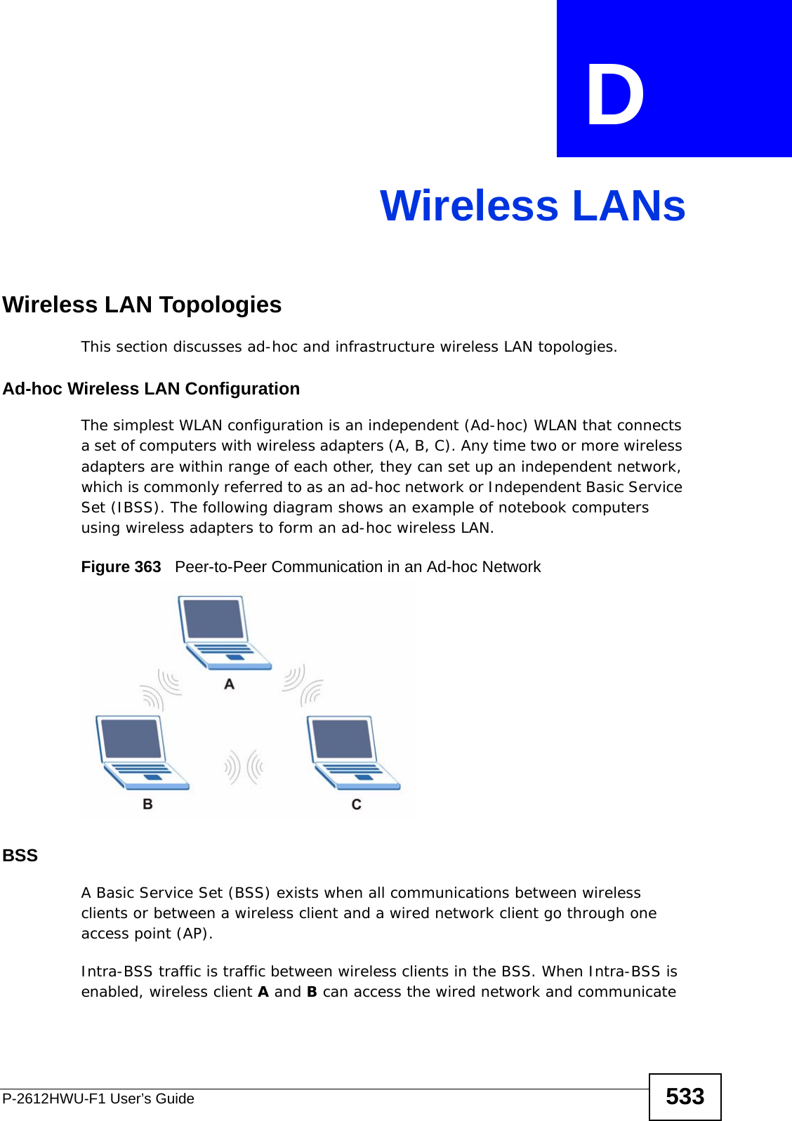
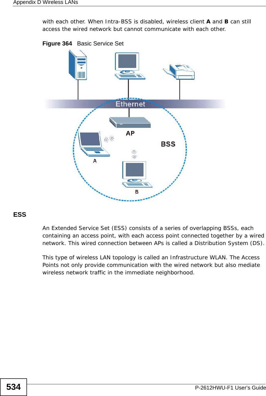
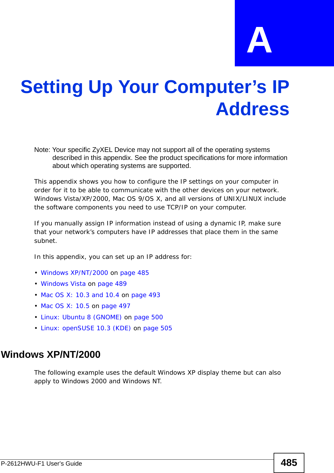
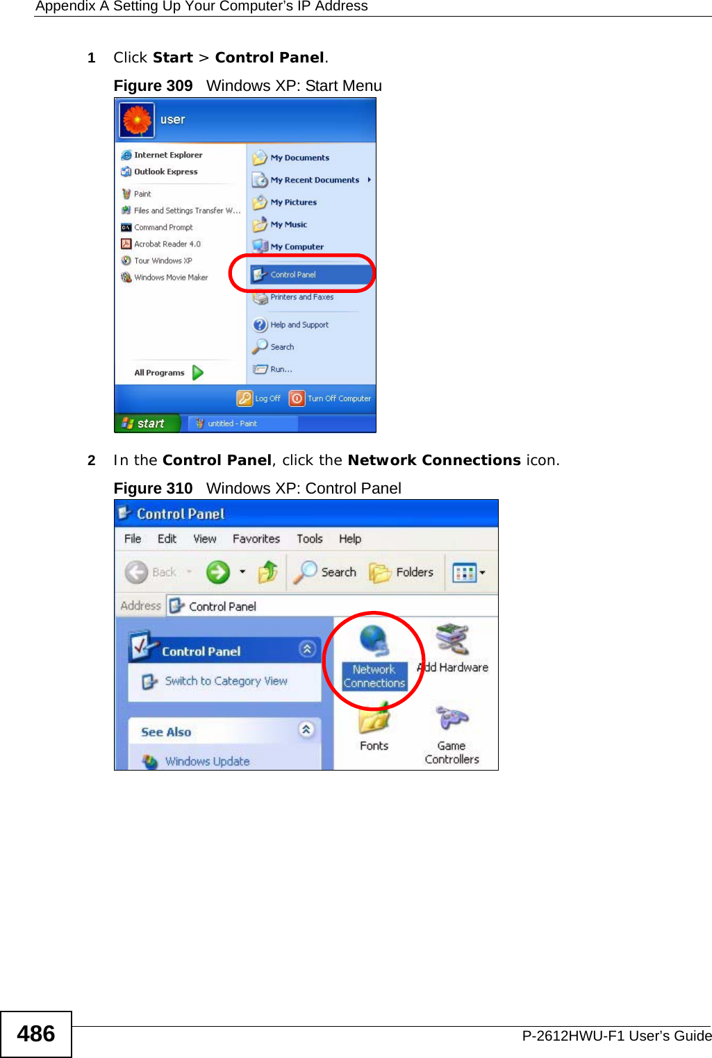
Usermanual part 4
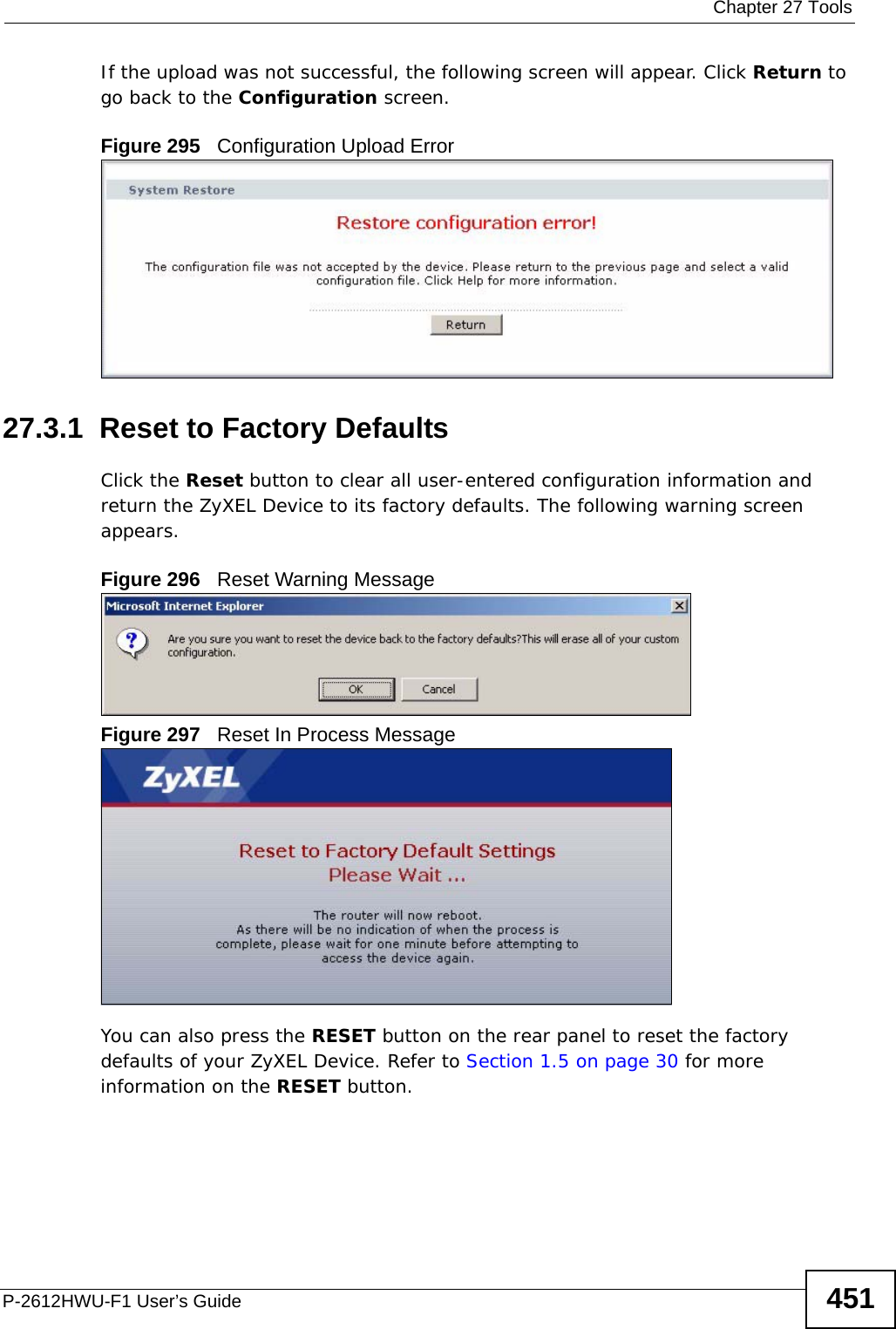
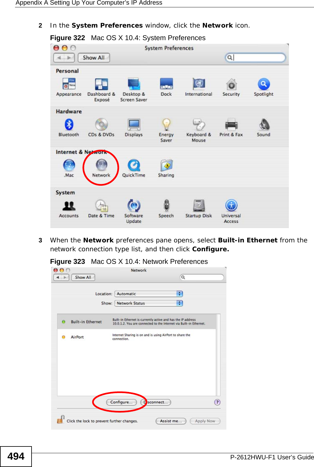
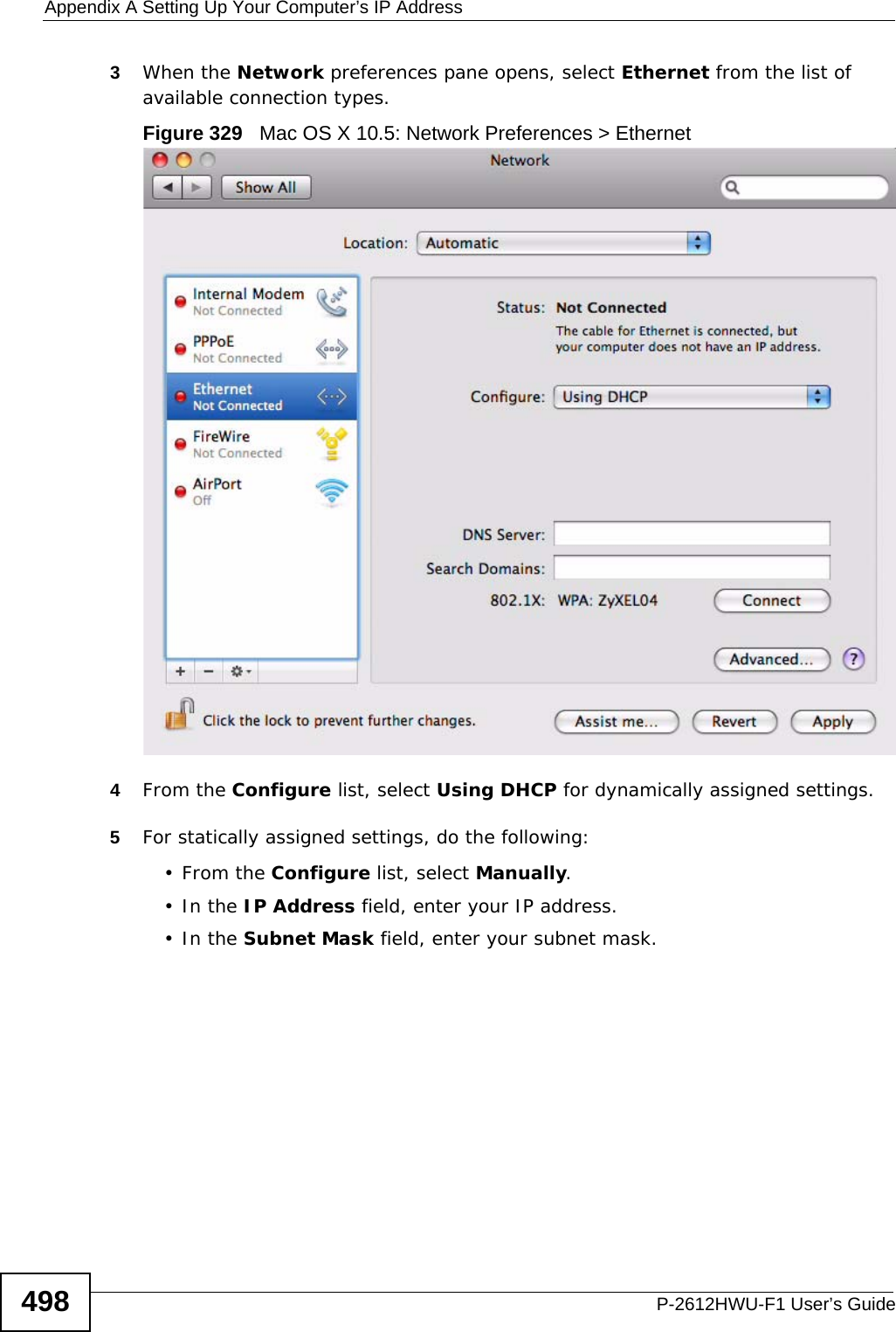
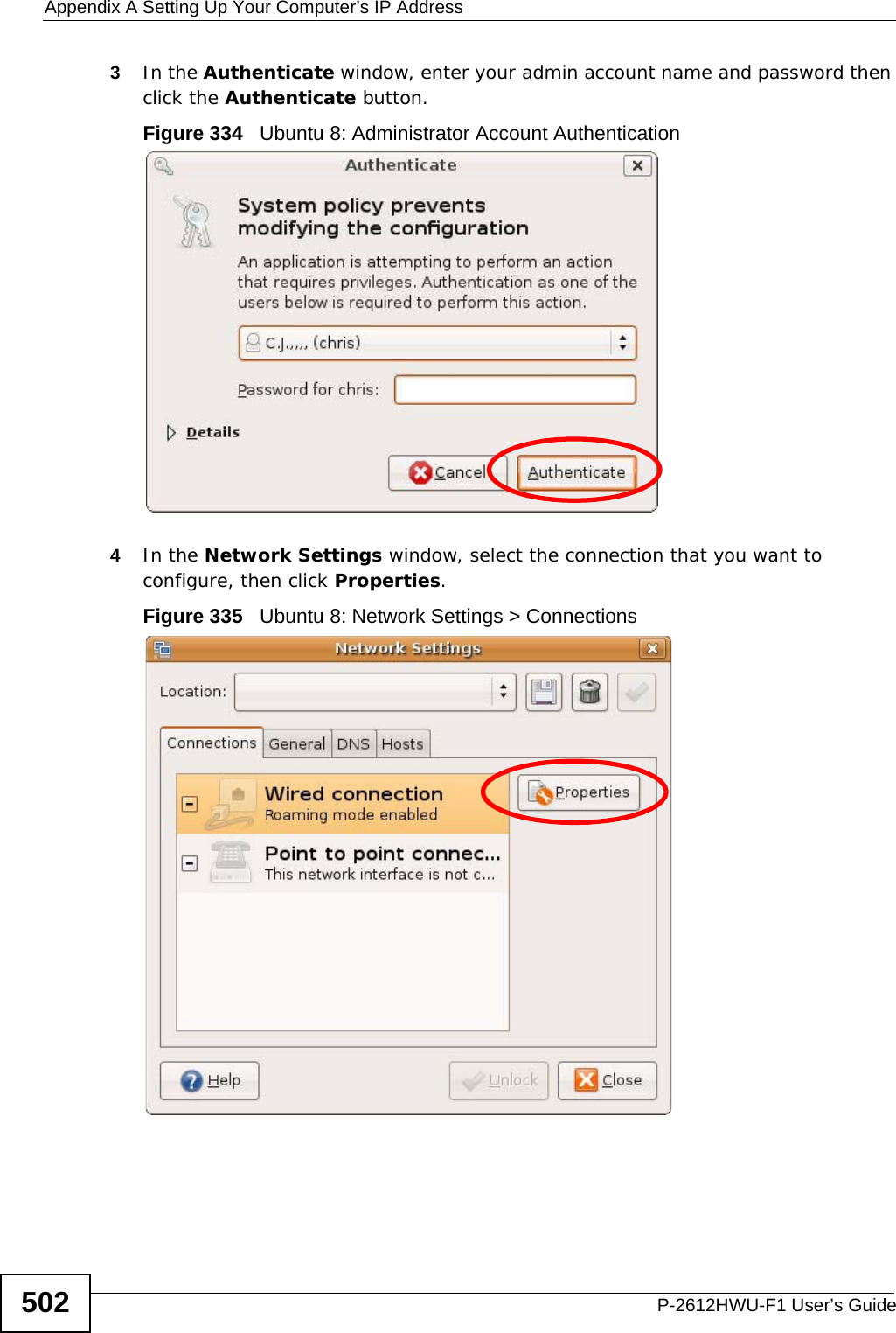
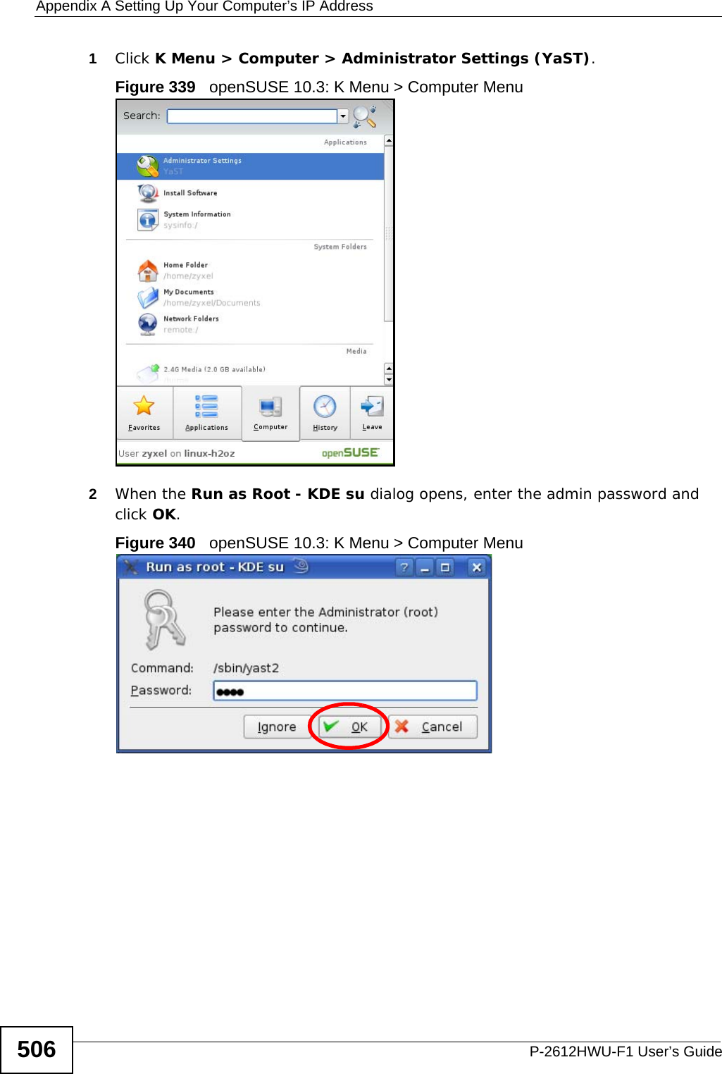
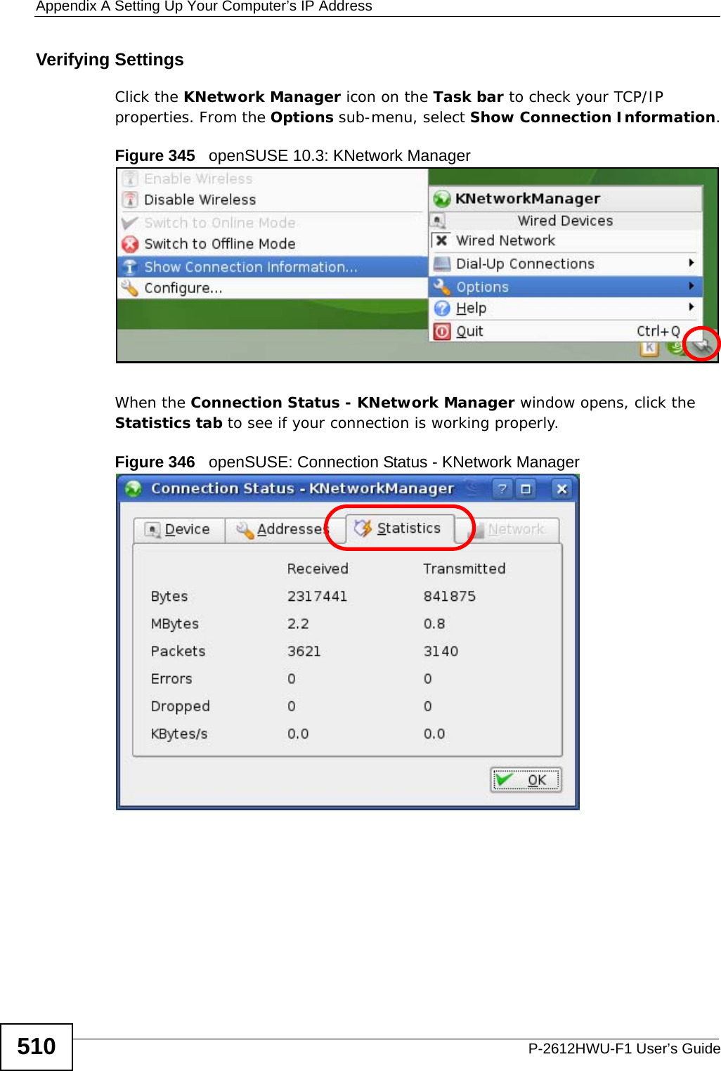
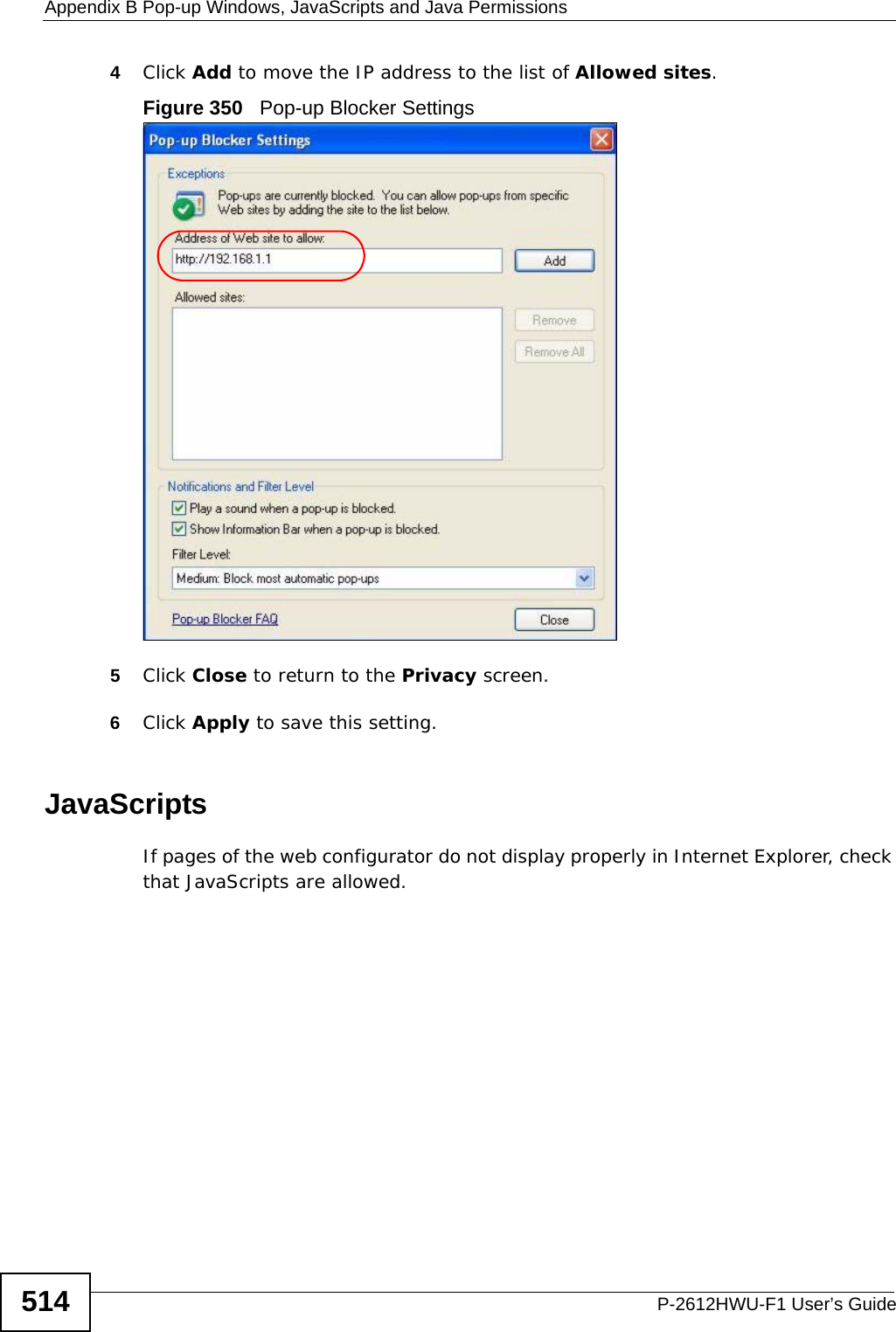
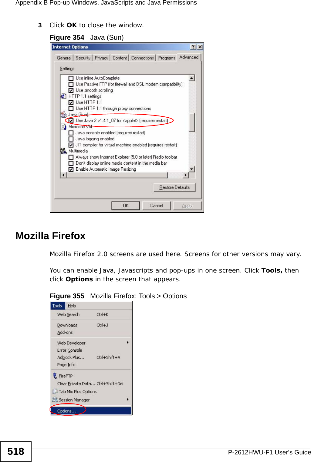
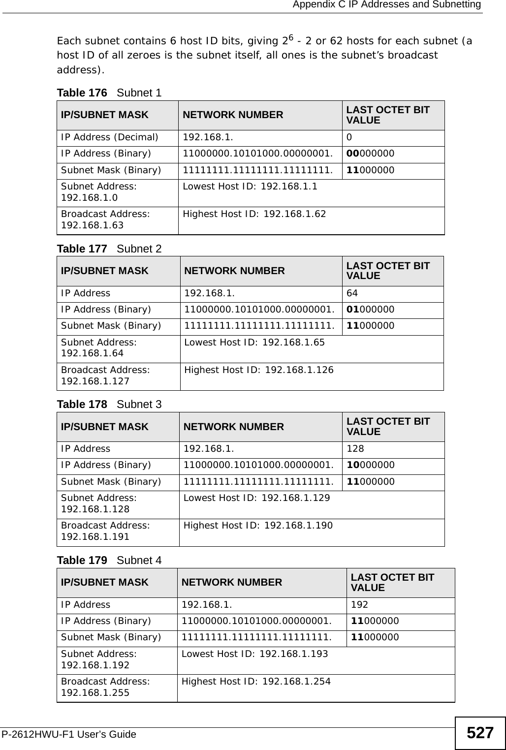
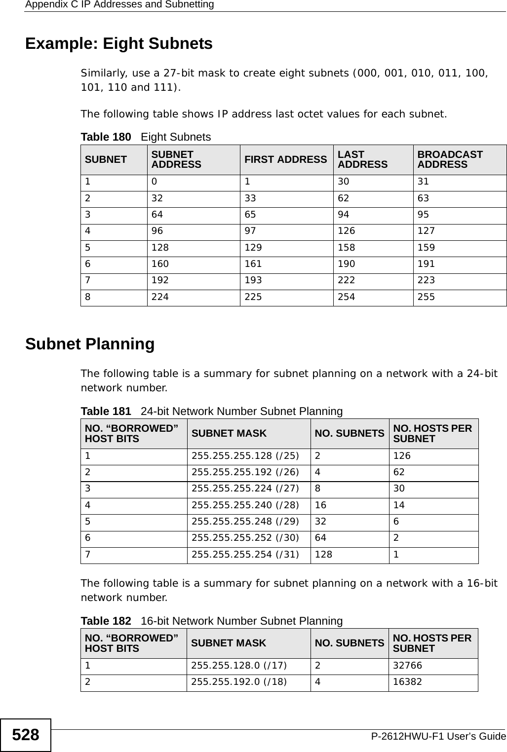
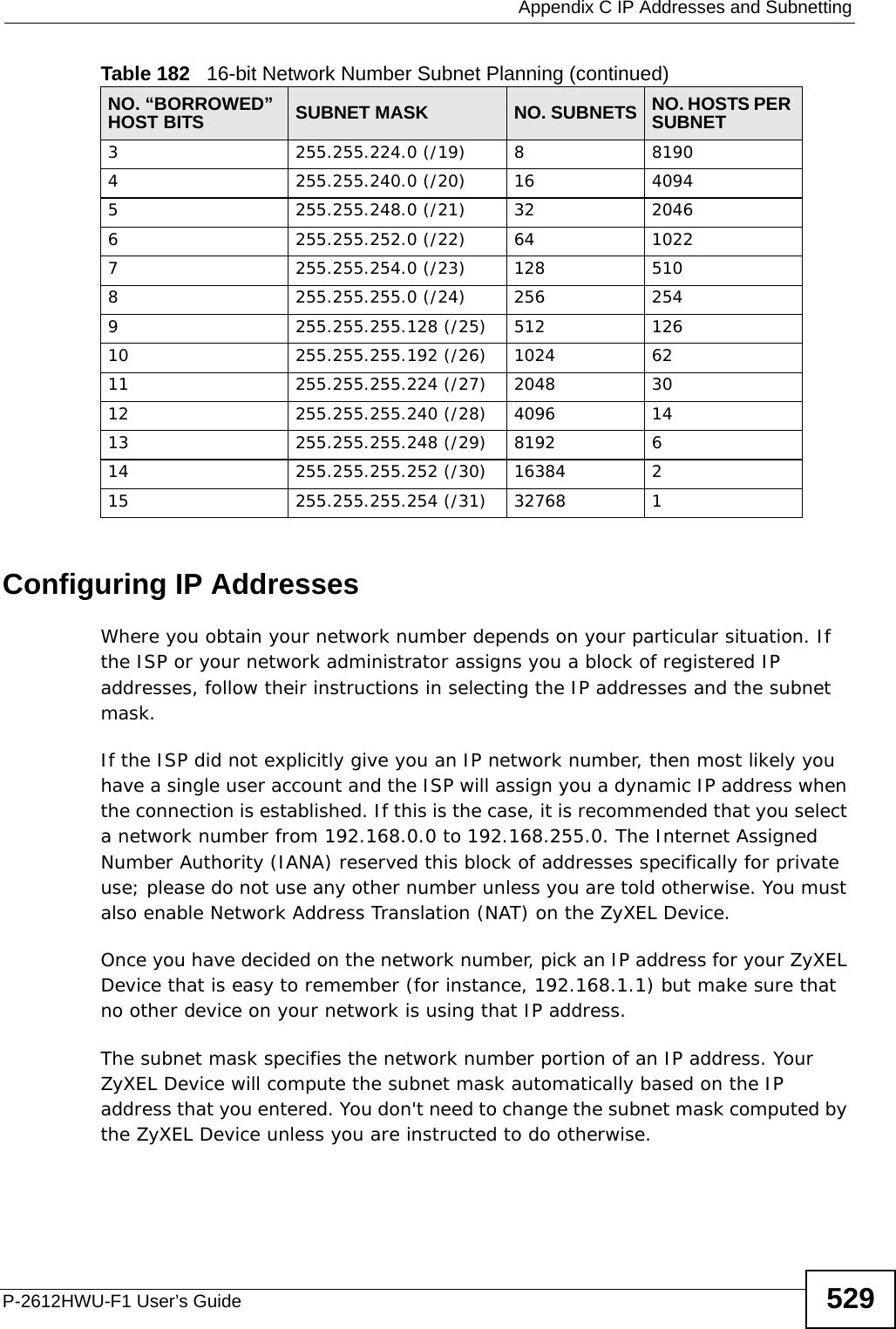
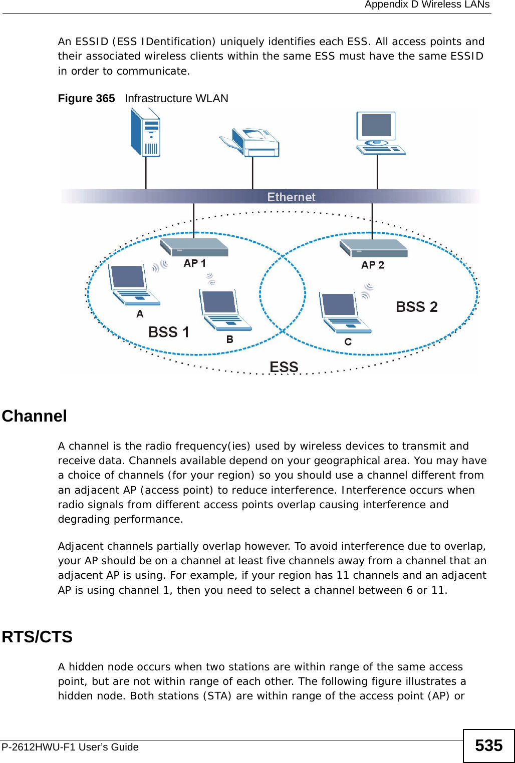
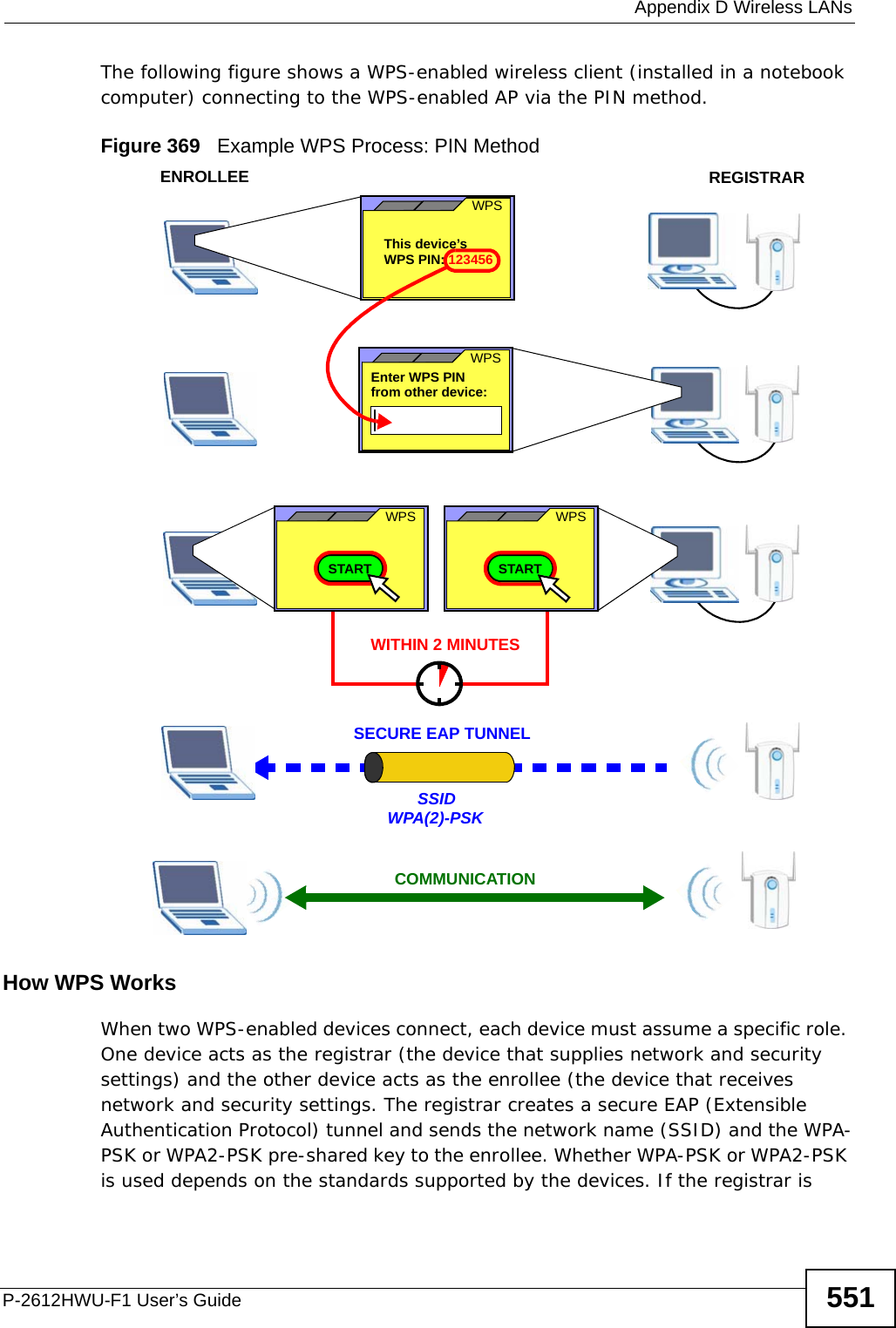
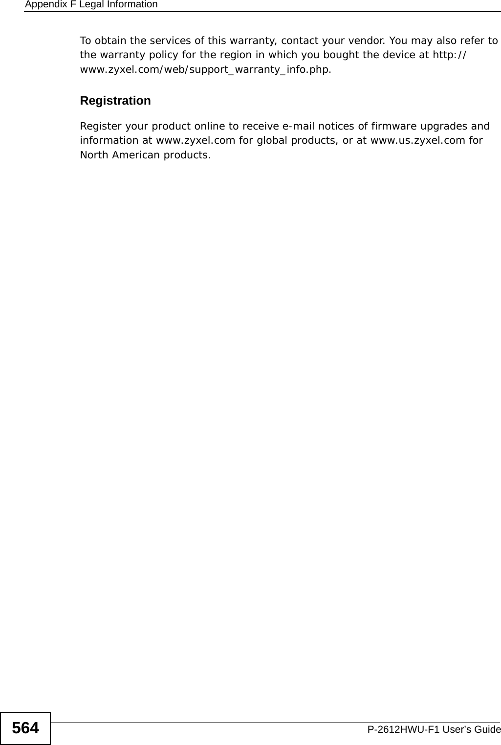
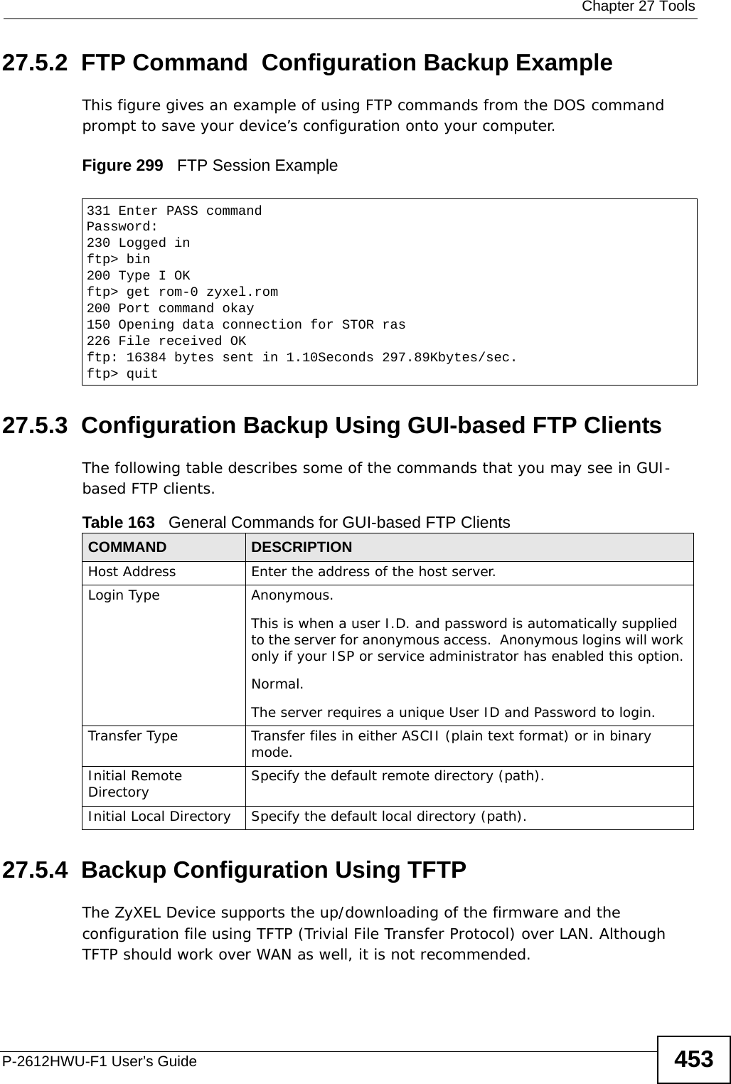
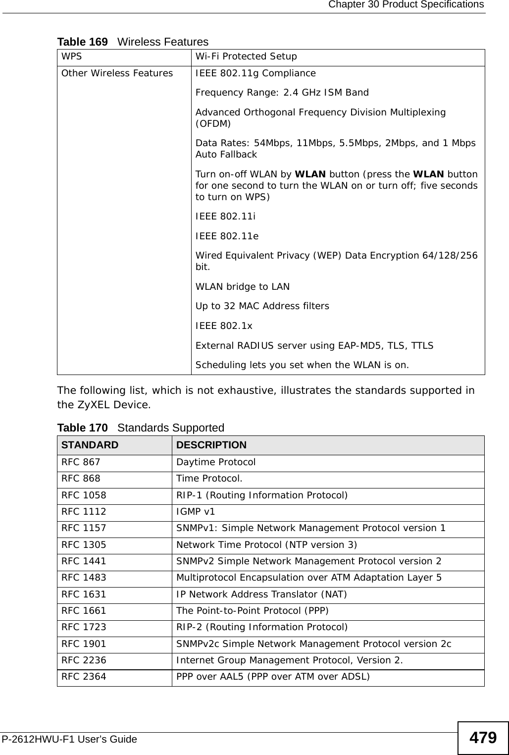
![Chapter 27 ToolsP-2612HWU-F1 User’s Guide45227.4 Restart System restart allows you to reboot the ZyXEL Device without turning the power off. Click Maintenance > Tools > Restart. Click Restart to have the ZyXEL Device reboot. This does not affect the ZyXEL Device's configuration. Figure 298 Maintenance > Tools > Restart Screen27.5 Using FTP or TFTP to Back Up ConfigurationThis section covers how to use FTP or TFTP to save your device’s configuration file to your computer.27.5.1 Using the FTP Commands to Back Up Configuration1Launch the FTP client on your computer.2Enter “open”, followed by a space and the IP address of your ZyXEL Device. 3Enter your username as requested (the default is “admin”).4Press [ENTER] when prompted for a password.5Enter “bin” to set transfer mode to binary.6Use “get” to transfer files from the ZyXEL Device to the computer, for example, “get rom-0 config.rom” transfers the configuration file on the ZyXEL Device to your computer and renames it “config.rom”. See earlier in this chapter for more information on filename conventions.7Enter “quit” to exit the ftp prompt.](https://usermanual.wiki/ZyXEL-Communications/P2612HWUFX.Usermanual-part-4/User-Guide-1154267-Page-2.png)
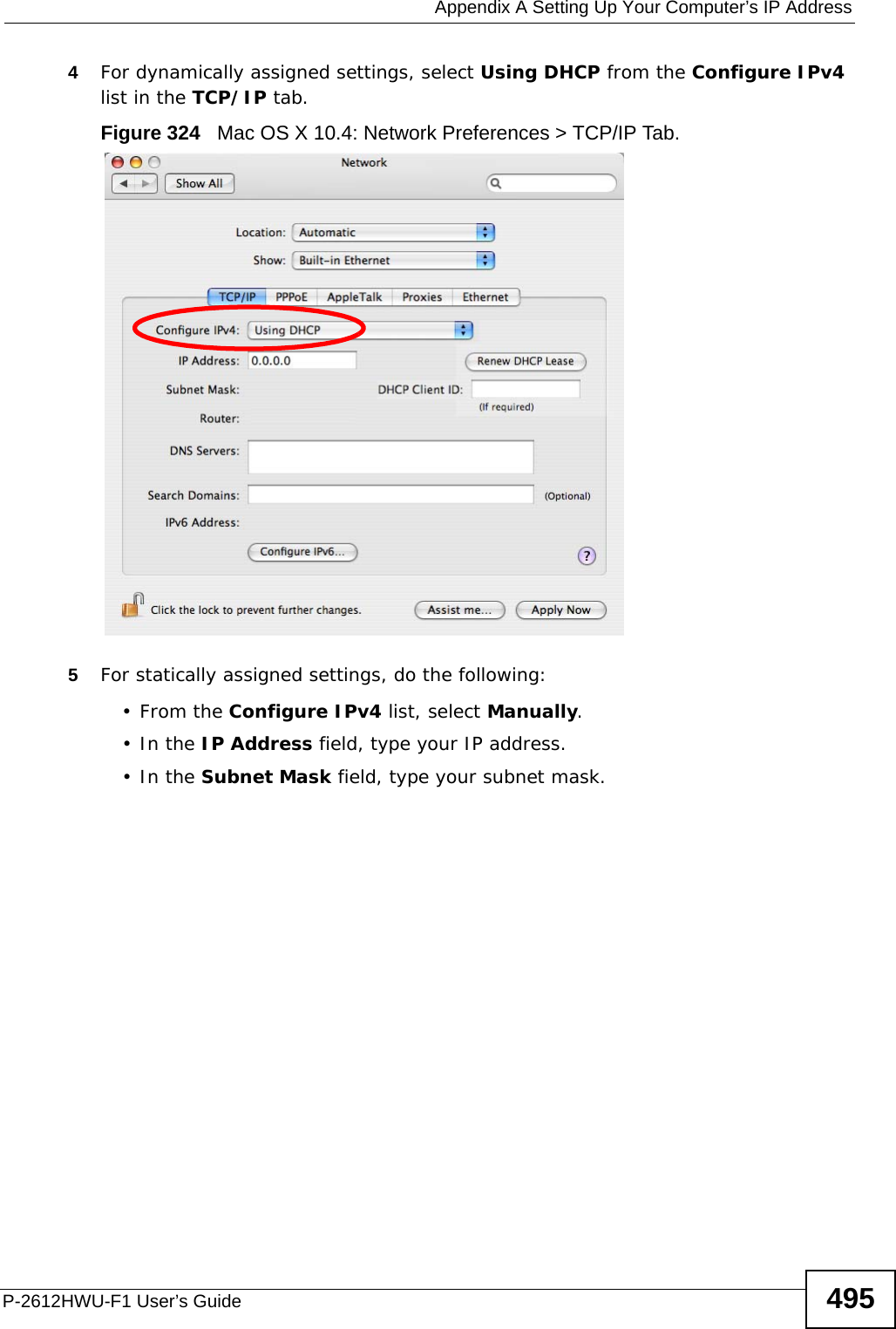
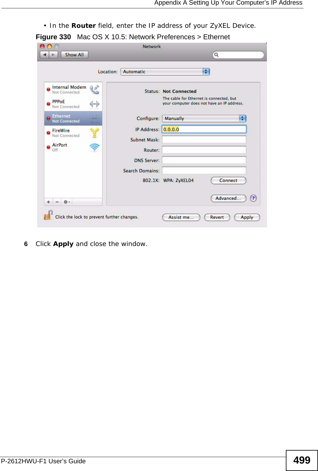
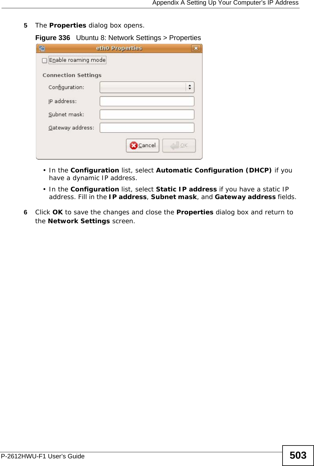
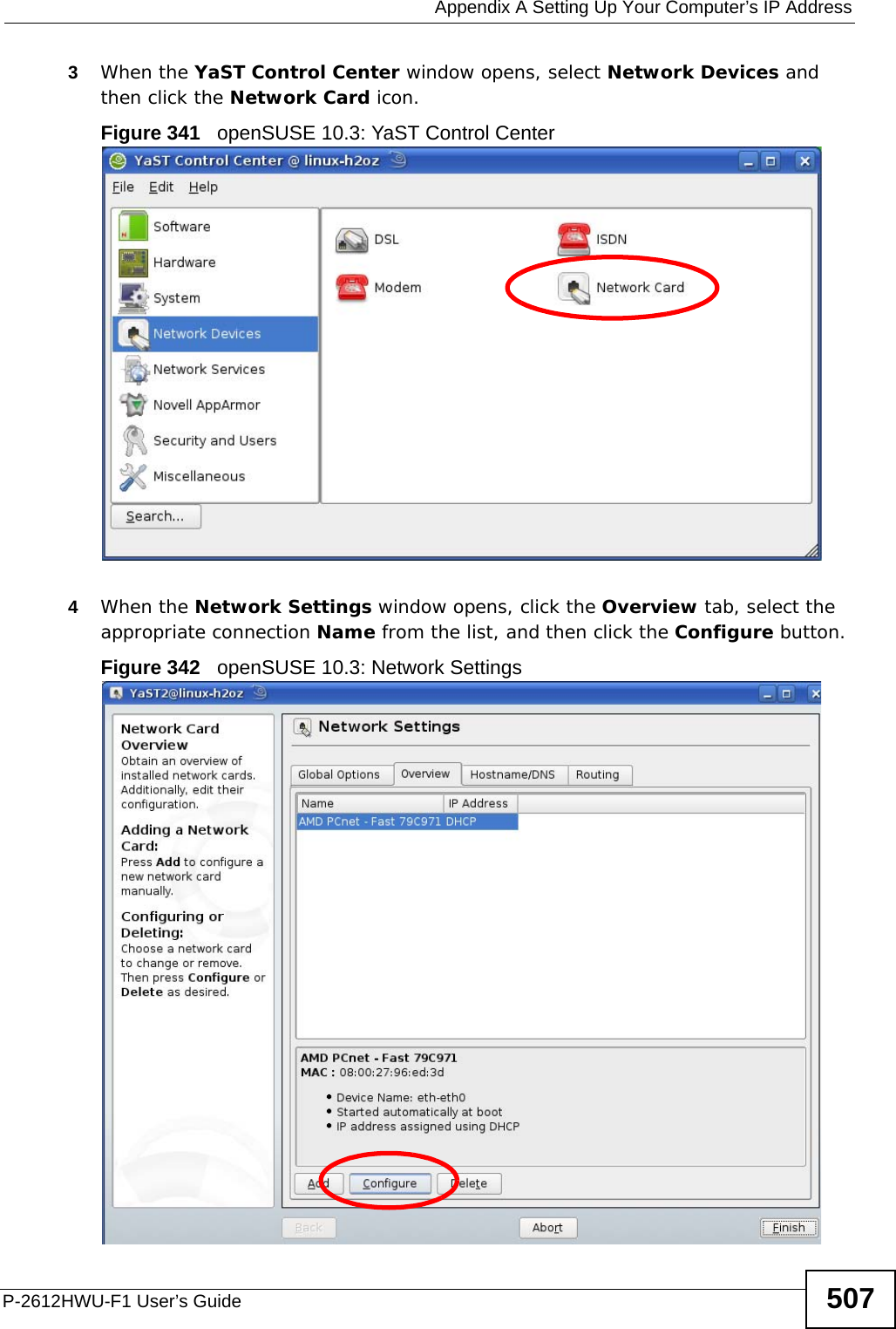
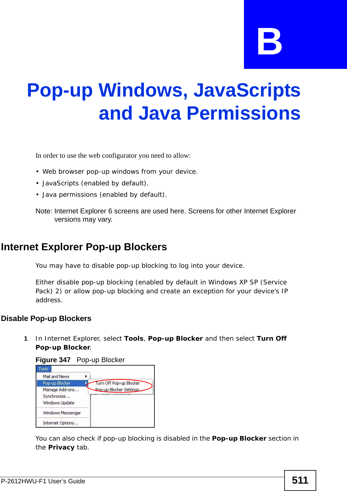
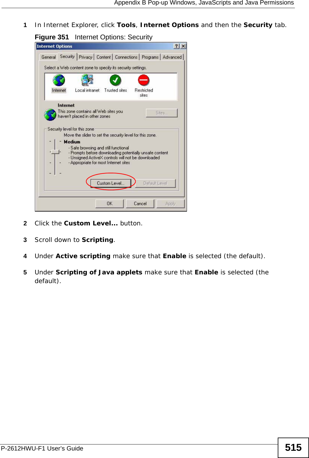
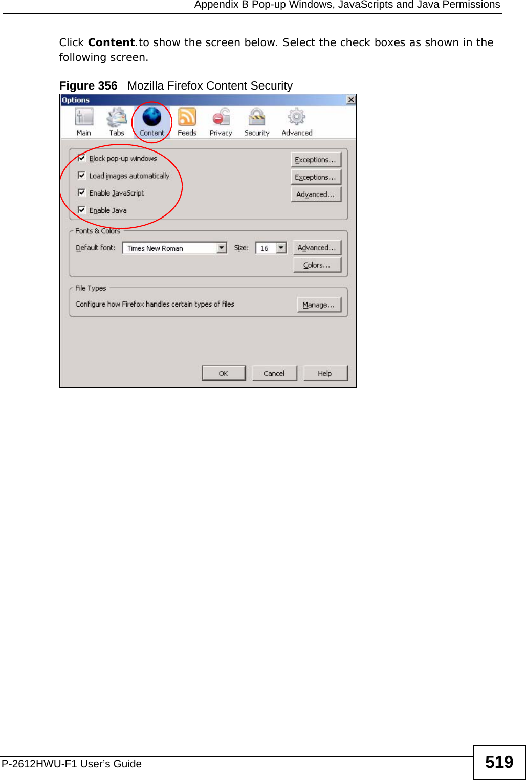
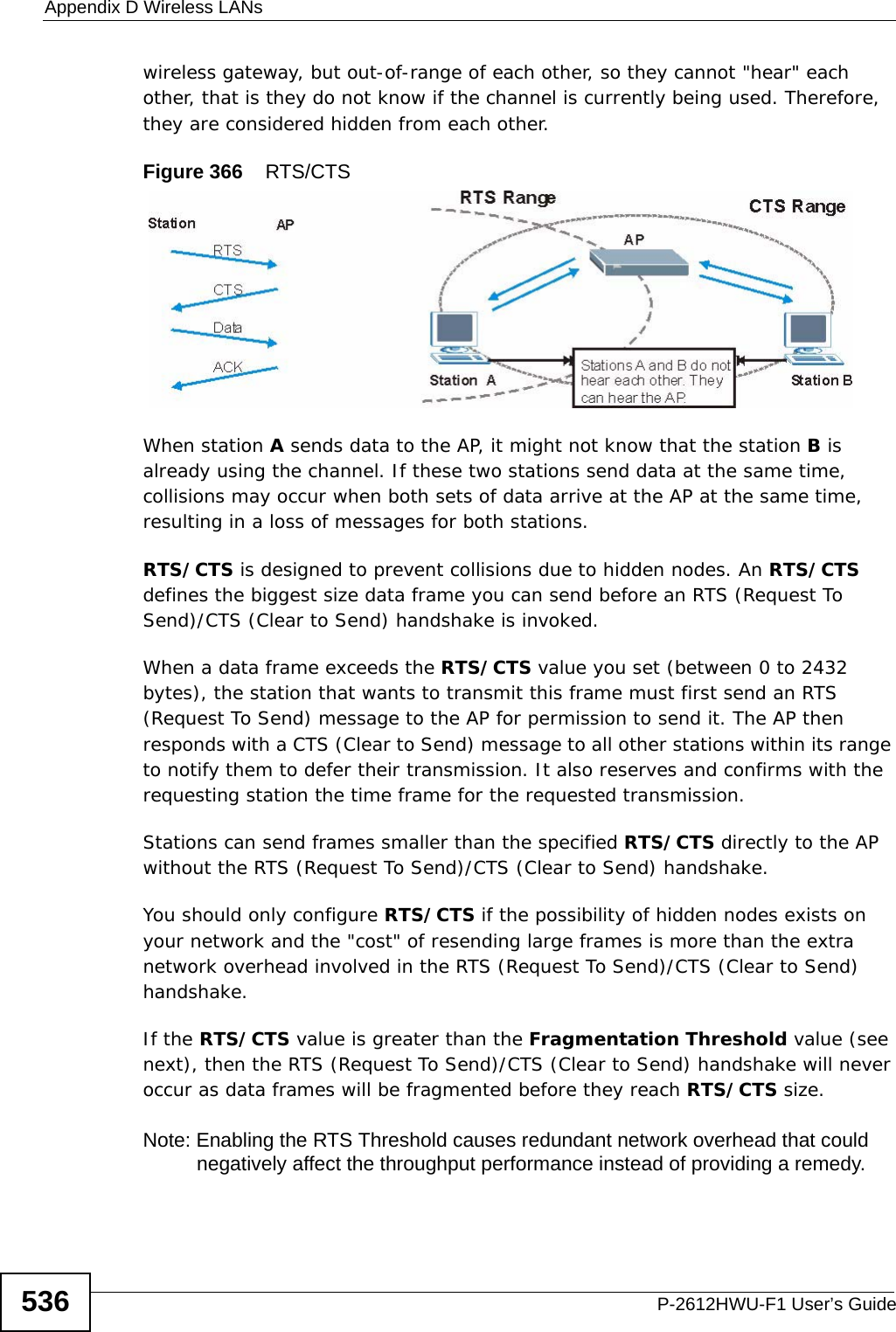
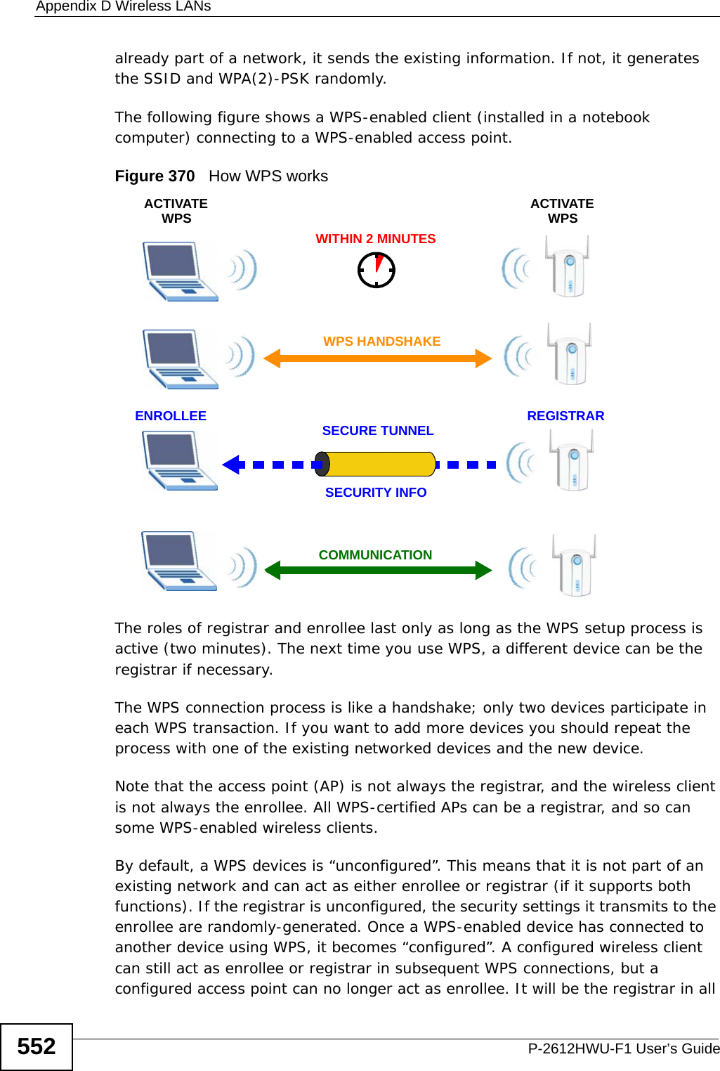
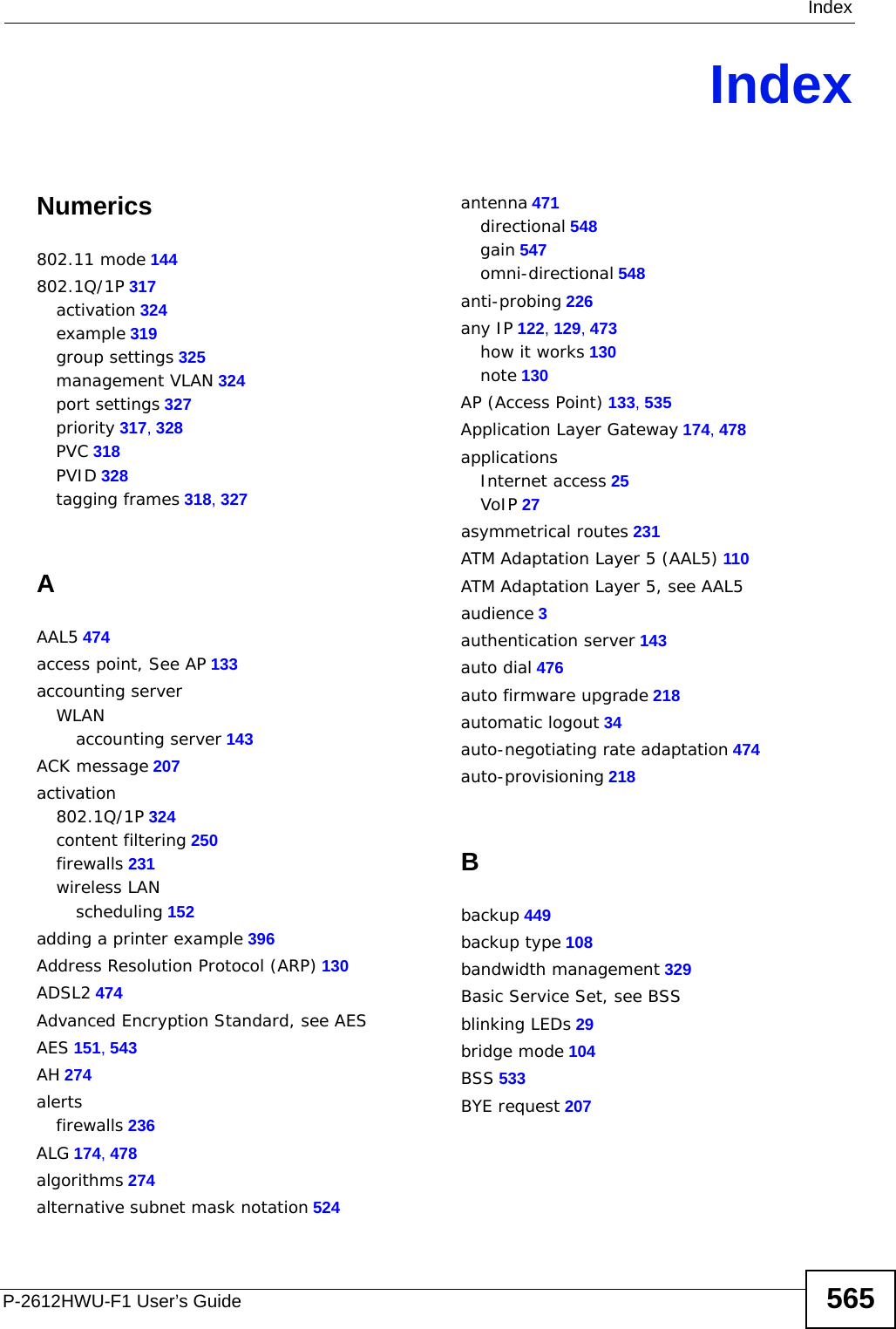
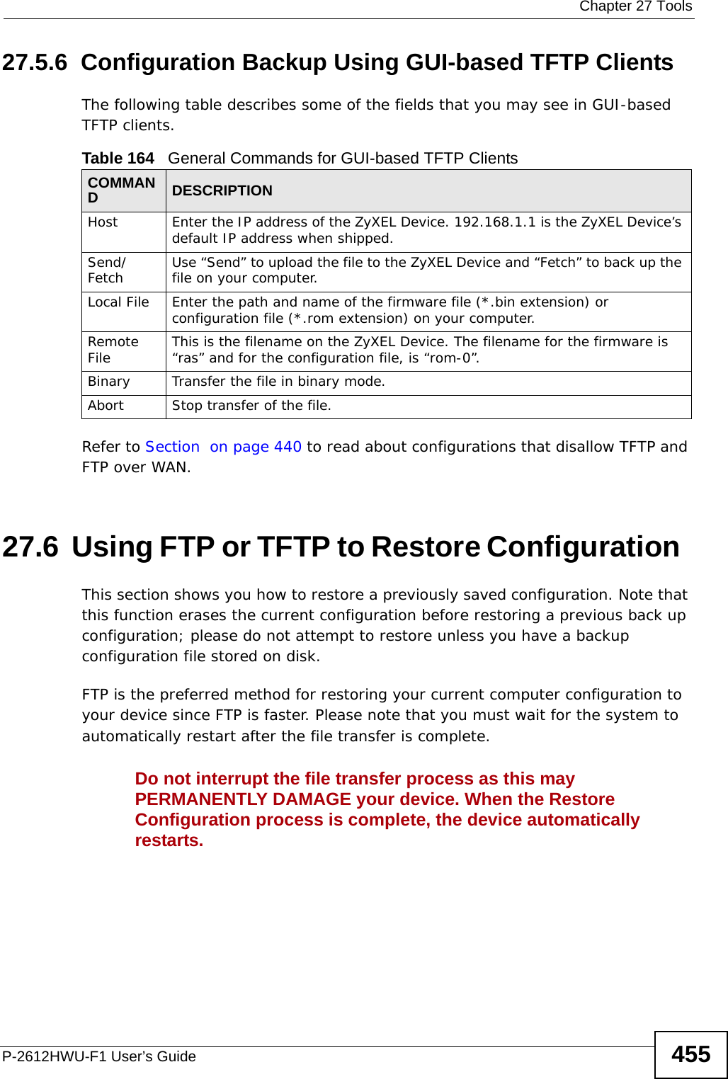
![Chapter 27 ToolsP-2612HWU-F1 User’s Guide454To use TFTP, your computer must have both telnet and TFTP clients. To backup the configuration file, follow the procedure shown next.1Use telnet from your computer to connect to the ZyXEL Device and log in. Because TFTP does not have any security checks, the ZyXEL Device records the IP address of the telnet client and accepts TFTP requests only from this address.2Enter command “sys stdio 0” to disable the management idle timeout, so the TFTP transfer will not be interrupted. Enter command “sys stdio 5” to restore the five-minute management idle timeout (default) when the file transfer is complete.3Launch the TFTP client on your computer and connect to the ZyXEL Device. Set the transfer mode to binary before starting data transfer.4Use the TFTP client (see the example below) to transfer files between the ZyXEL Device and the computer. The file name for the configuration file is “rom-0” (rom-zero, not capital o).Note that the telnet connection must be active before and during the TFTP transfer. For details on TFTP commands (see following example), please consult the documentation of your TFTP client program. For UNIX, use “get” to transfer from the ZyXEL Device to the computer and “binary” to set binary transfer mode.27.5.5 TFTP Command Configuration Backup ExampleThe following is an example TFTP command:tftp [-i] host get rom-0 config.romwhere “i” specifies binary image transfer mode (use this mode when transferring binary files), “host” is the ZyXEL Device IP address, “get” transfers the file source on the ZyXEL Device (rom-0, name of the configuration file on the ZyXEL Device) to the file destination on the computer and renames it config.rom.](https://usermanual.wiki/ZyXEL-Communications/P2612HWUFX.Usermanual-part-4/User-Guide-1154267-Page-4.png)
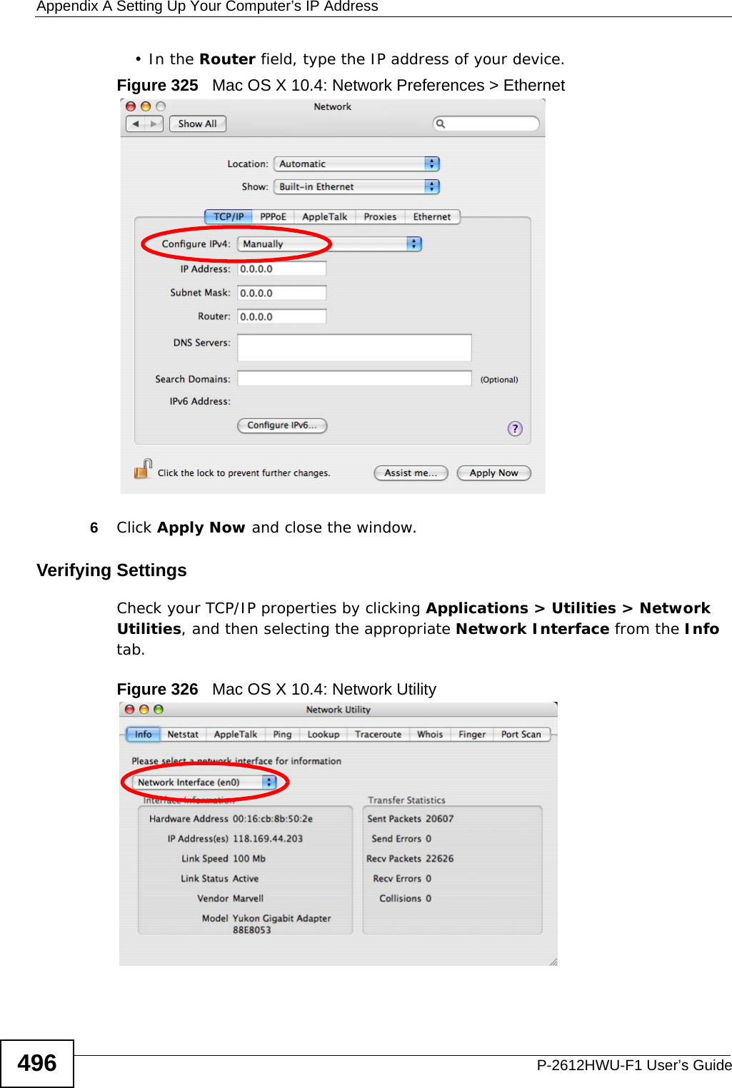
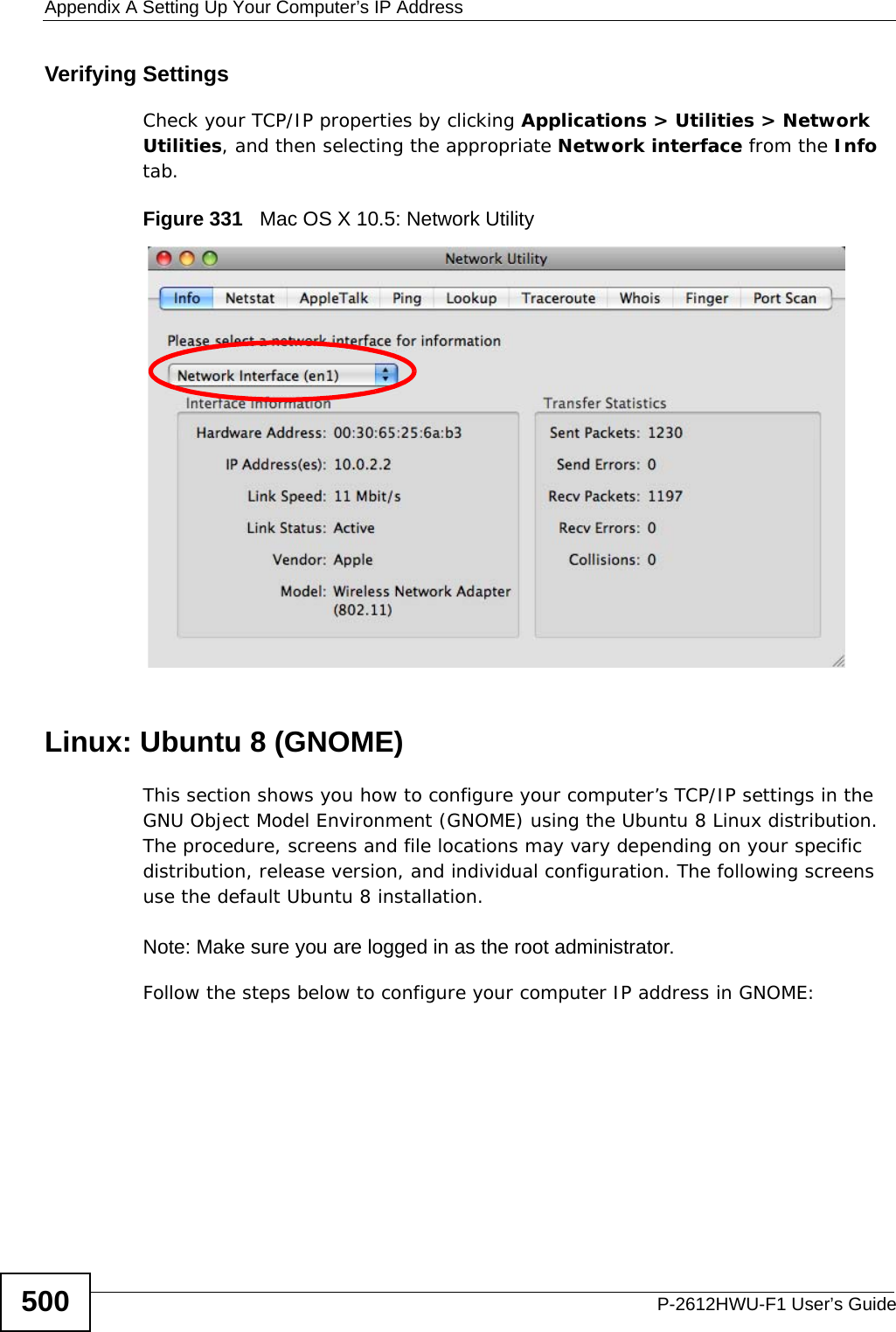
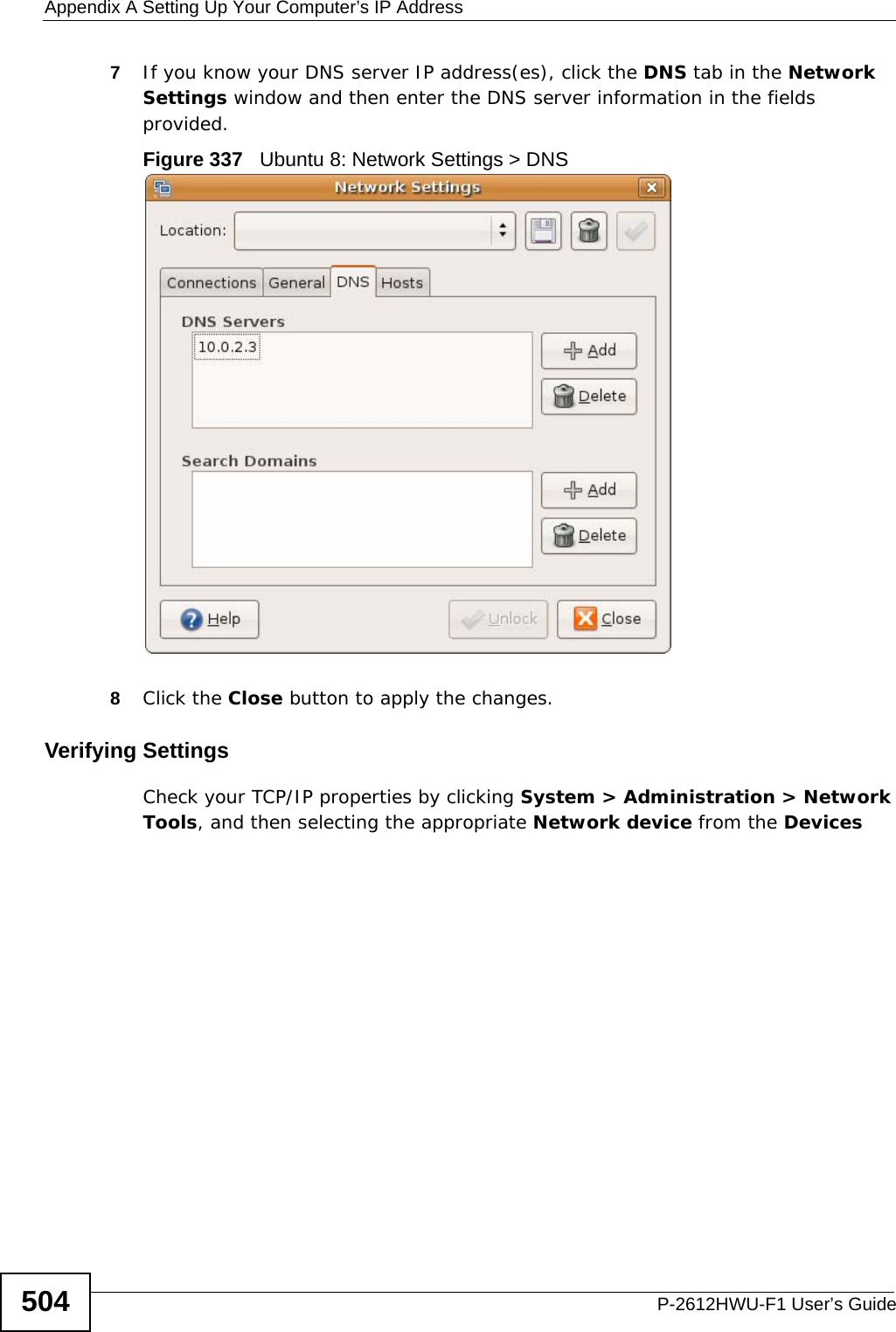
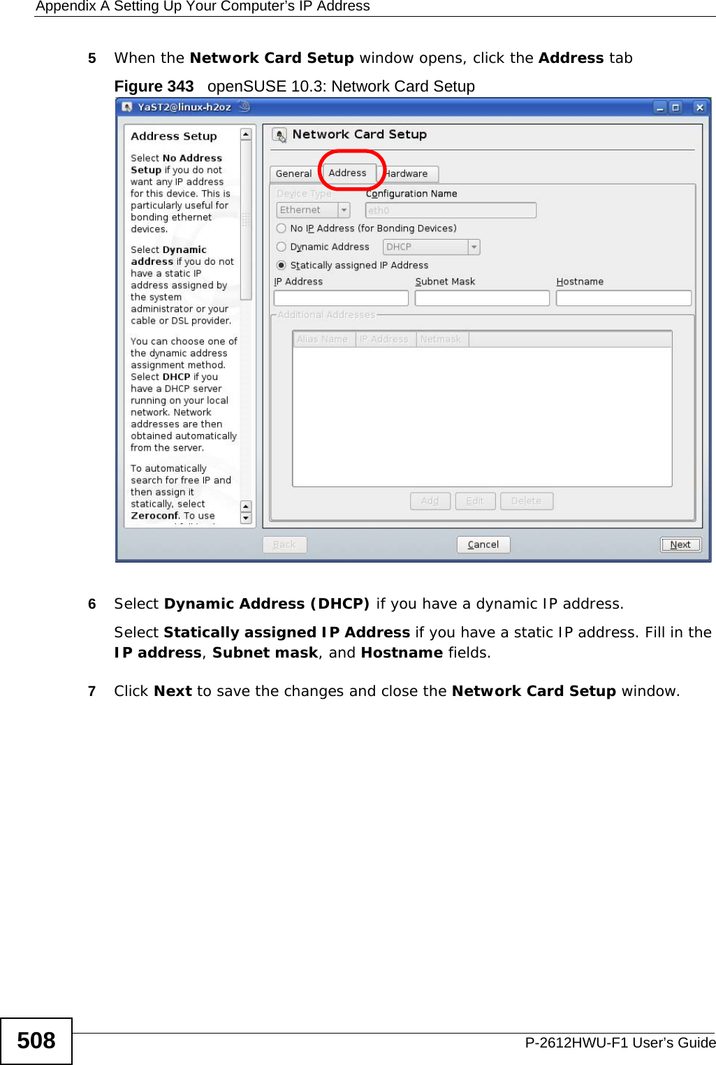
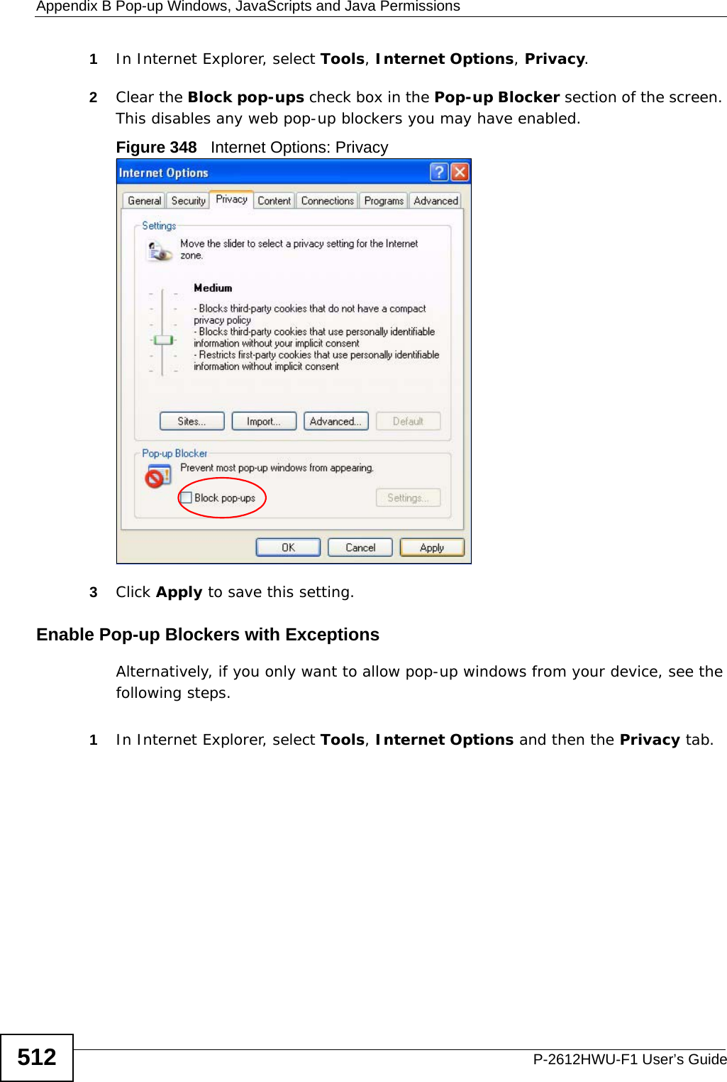
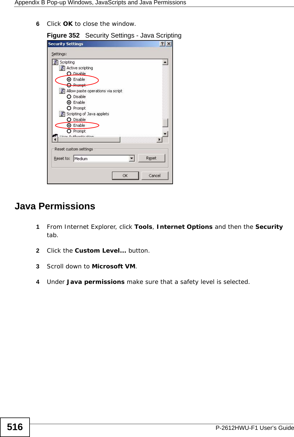
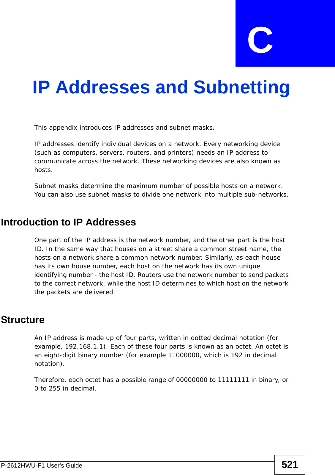
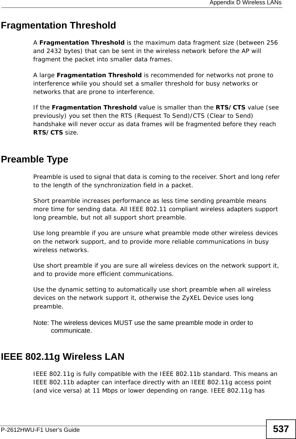
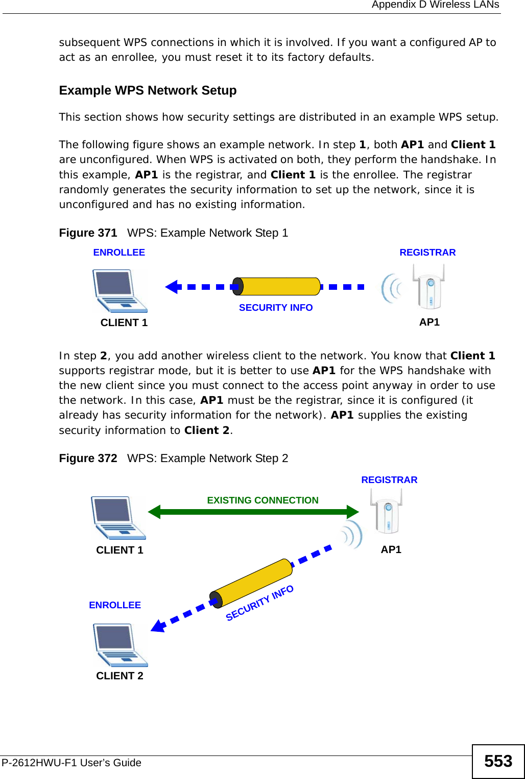
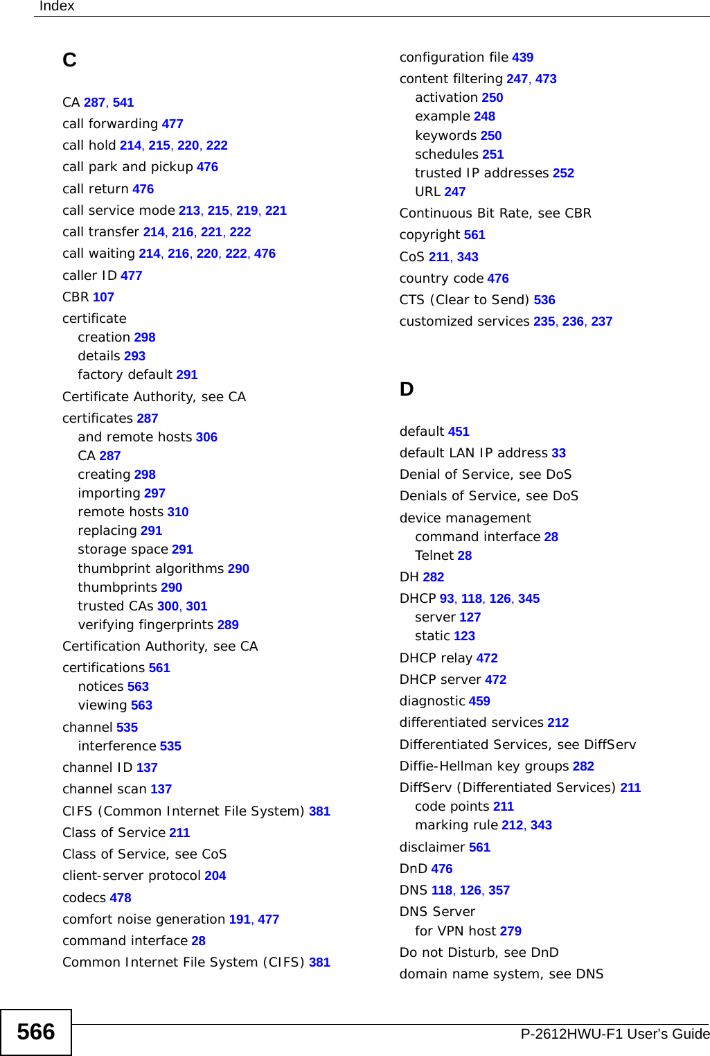
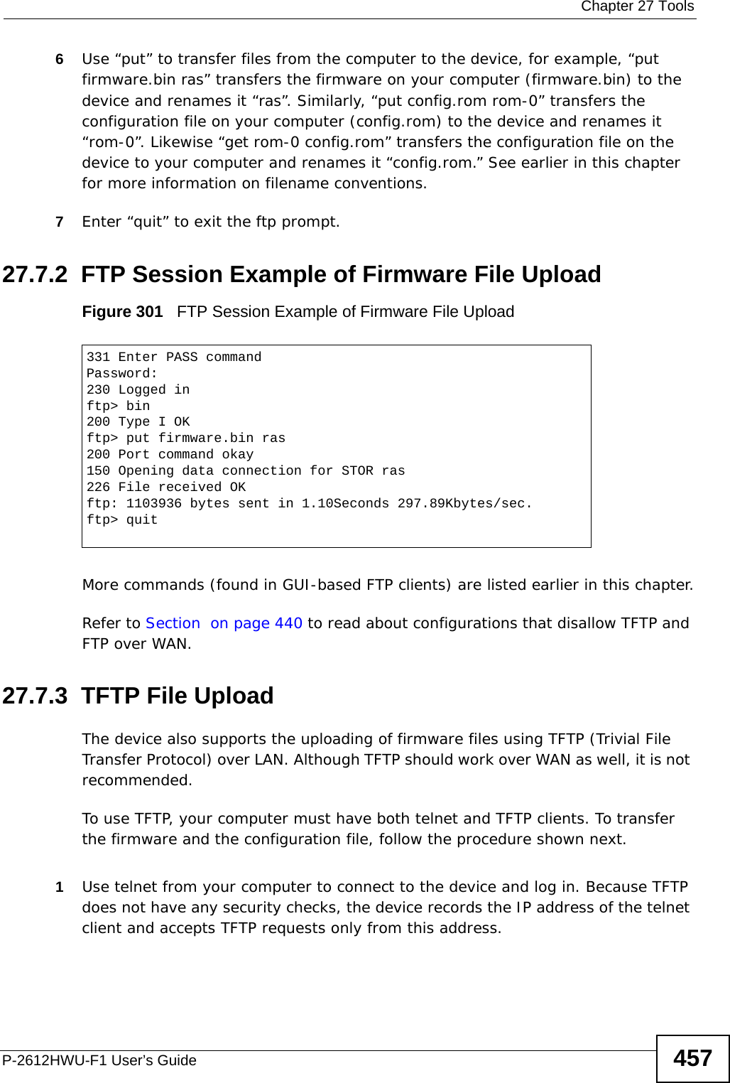
![Chapter 27 ToolsP-2612HWU-F1 User’s Guide45627.6.1 Restore Using FTP Session ExampleFigure 300 Restore Using FTP Session ExampleRefer to Section on page 440 to read about configurations that disallow TFTP and FTP over WAN.27.7 FTP and TFTP Firmware and Configuration File UploadsThis section shows you how to upload firmware and configuration files. Do not interrupt the file transfer process as this may PERMANENTLY DAMAGE your device. FTP is the preferred method for uploading the firmware and configuration. To use this feature, your computer must have an FTP client. The following sections give examples of how to upload the firmware and the configuration files.27.7.1 FTP File Upload Command from the DOS Prompt Example1Launch the FTP client on your computer.2Enter “open”, followed by a space and the IP address of your device. 3Enter your username as requested (the default is “admin”).4Press [ENTER] when prompted for a password.5Enter “bin” to set transfer mode to binary.ftp> put config.rom rom-0200 Port command okay150 Opening data connection for STOR rom-0226 File received OK221 Goodbye for writing flashftp: 16384 bytes sent in 0.06Seconds 273.07Kbytes/sec.ftp>quit](https://usermanual.wiki/ZyXEL-Communications/P2612HWUFX.Usermanual-part-4/User-Guide-1154267-Page-6.png)
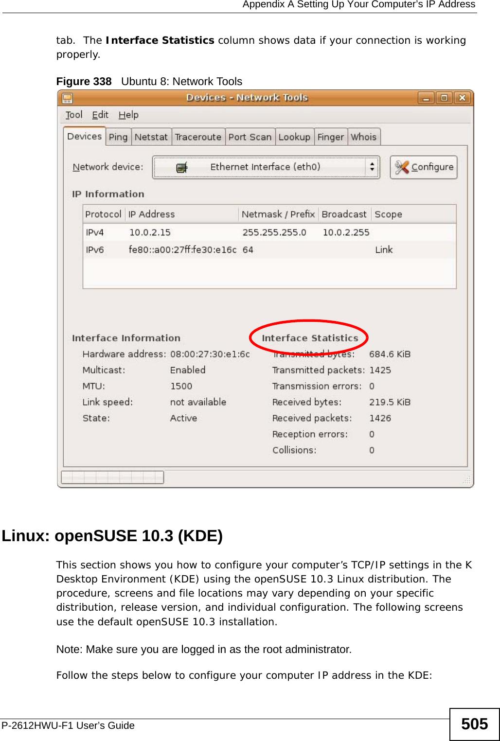
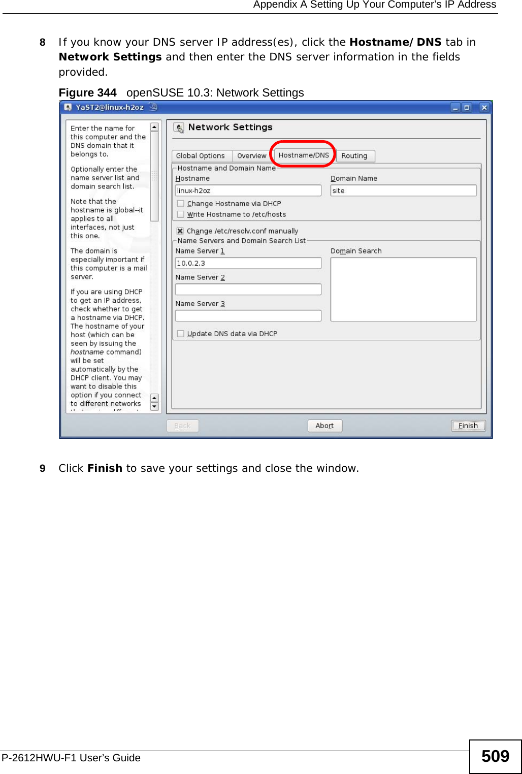
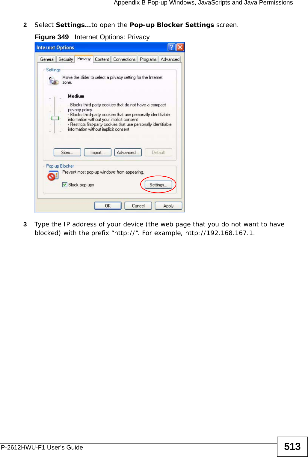
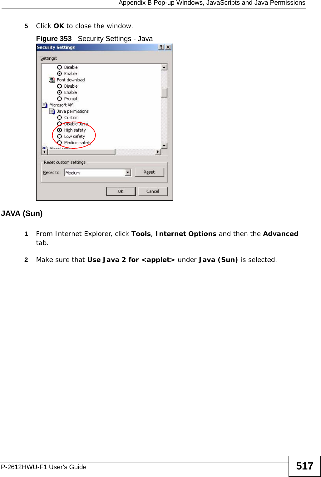
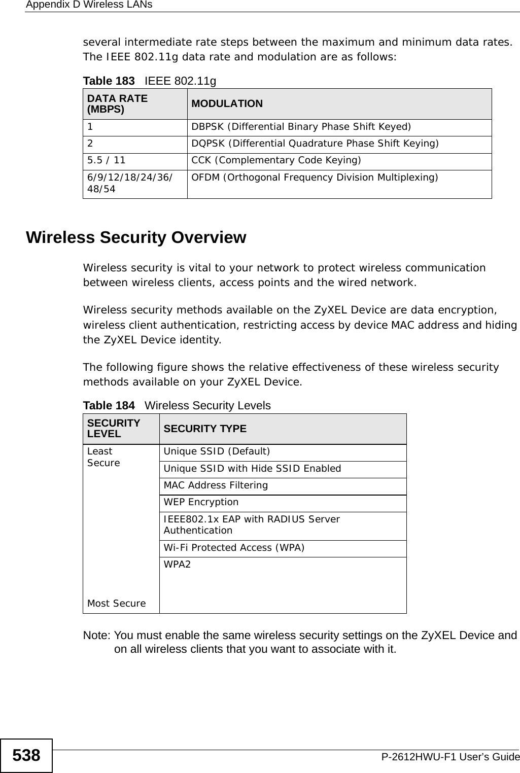
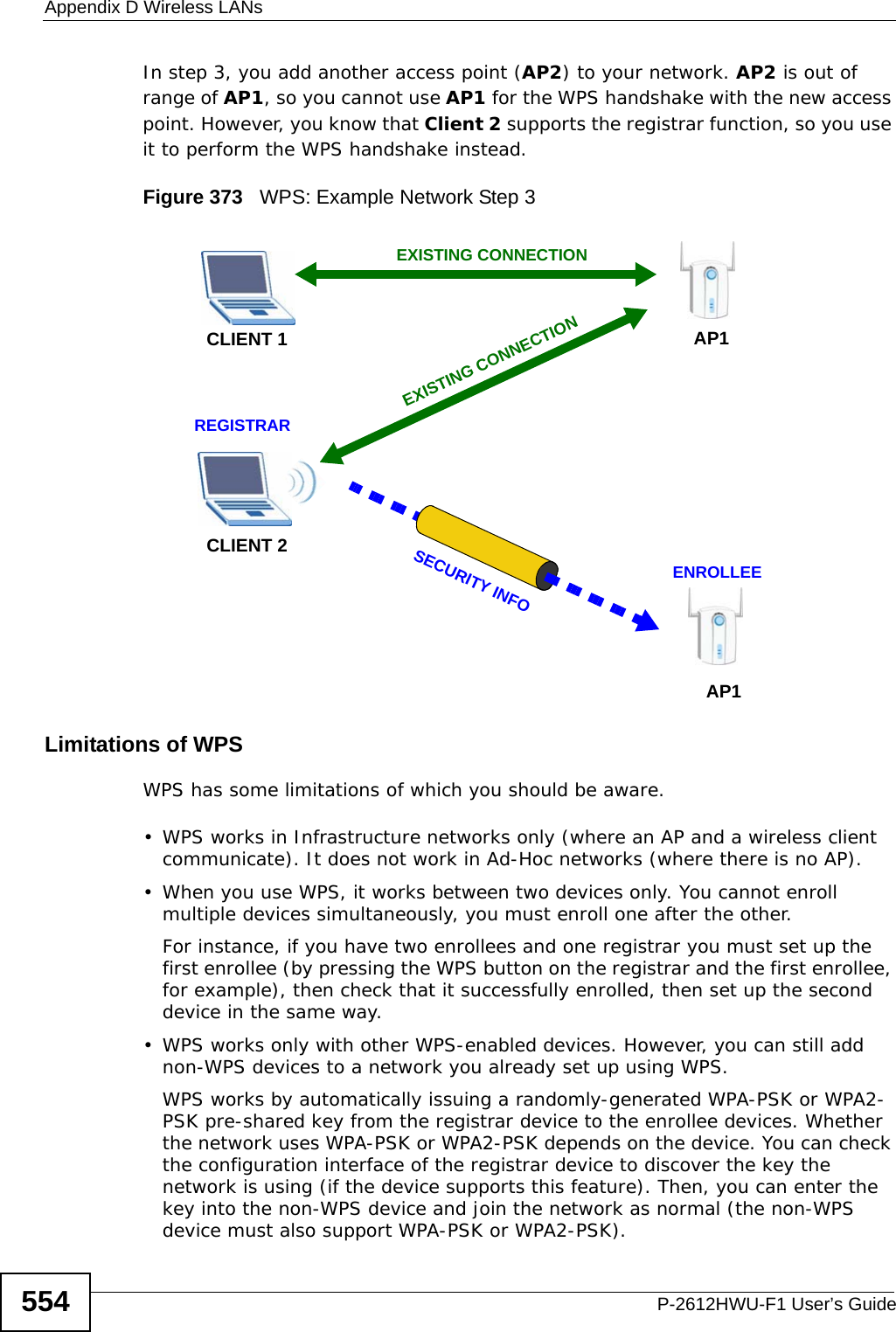
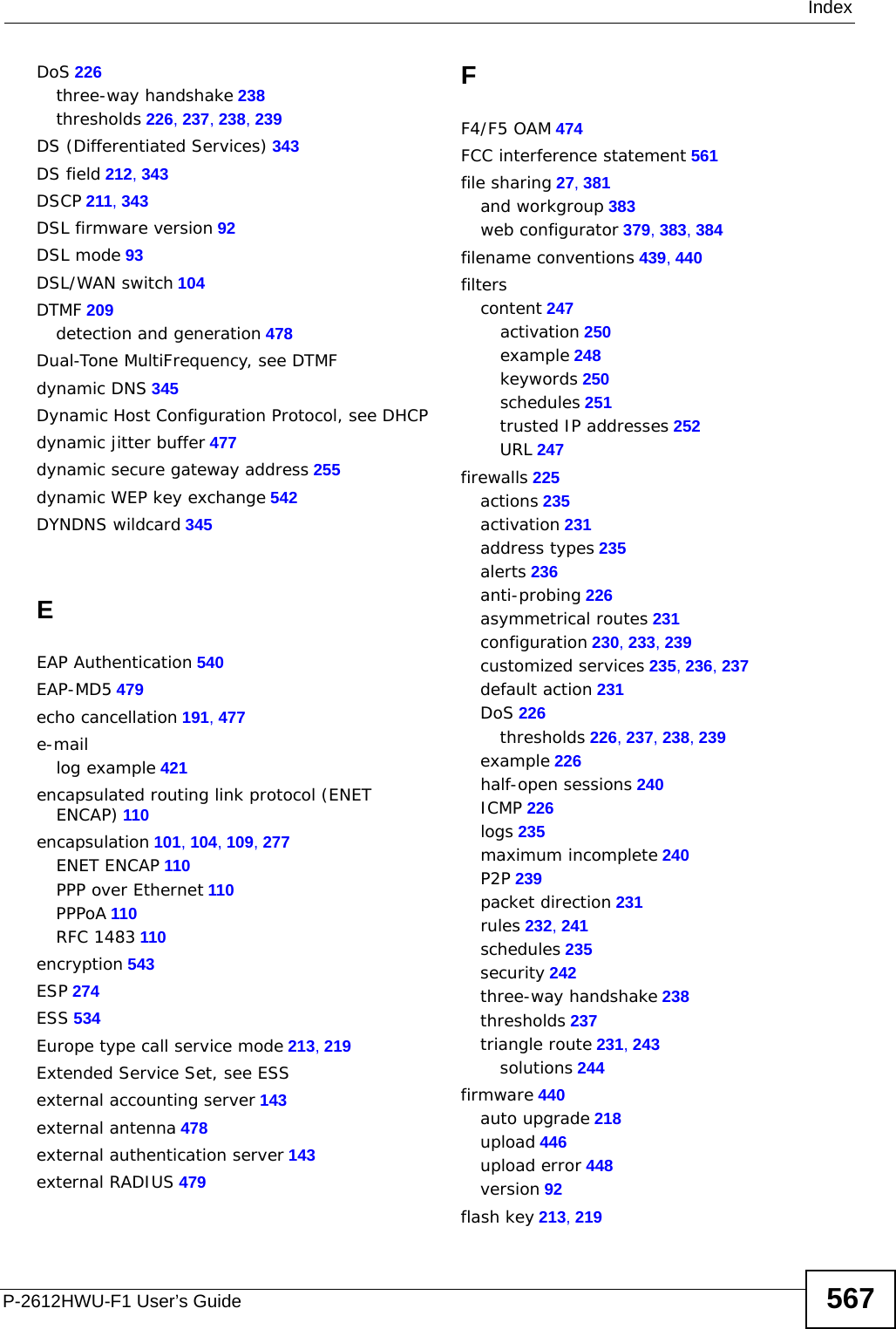
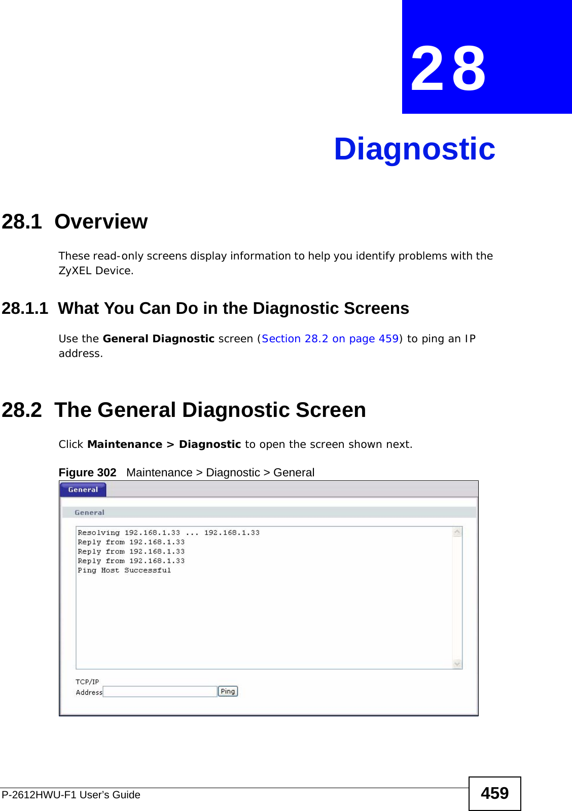
![Chapter 27 ToolsP-2612HWU-F1 User’s Guide4582Enter the command “sys stdio 0” to disable the management idle timeout, so the TFTP transfer will not be interrupted. Enter “command sys stdio 5” to restore the five-minute management idle timeout (default) when the file transfer is complete.3Launch the TFTP client on your computer and connect to the device. Set the transfer mode to binary before starting data transfer.4Use the TFTP client (see the example below) to transfer files between the device and the computer. The file name for the firmware is “ras”.Note that the telnet connection must be active and the device in CI mode before and during the TFTP transfer. For details on TFTP commands (see following example), please consult the documentation of your TFTP client program. For UNIX, use “get” to transfer from the device to the computer, “put” the other way around, and “binary” to set binary transfer mode.27.7.4 TFTP Upload Command ExampleThe following is an example TFTP command:tftp [-i] host put firmware.bin rasWhere “i” specifies binary image transfer mode (use this mode when transferring binary files), “host” is the device’s IP address, “put” transfers the file source on the computer (firmware.bin – name of the firmware on the computer) to the file destination on the remote host (ras - name of the firmware on the device).Commands that you may see in GUI-based TFTP clients are listed earlier in this chapter.](https://usermanual.wiki/ZyXEL-Communications/P2612HWUFX.Usermanual-part-4/User-Guide-1154267-Page-8.png)
![Chapter 29 TroubleshootingP-2612HWU-F1 User’s Guide 463• If you changed the IP address and have forgotten it, see the troubleshooting suggestions for I forgot the IP address for the ZyXEL Device.2Check the hardware connections, and make sure the LEDs are behaving as expected. See the Quick Start Guide.3Make sure your Internet browser does not block pop-up windows and has JavaScripts and Java enabled. See Appendix B on page 511.4If you disabled Any IP (Section 7.2.1 on page 120), make sure your computer is in the same subnet as the ZyXEL Device. (If you know that there are routers between your computer and the ZyXEL Device, skip this step.) • If there is a DHCP server on your network, make sure your computer is using a dynamic IP address. See Appendix A on page 485. Your ZyXEL Device is a DHCP server by default.• If there is no DHCP server on your network, make sure your computer’s IP address is in the same subnet as the ZyXEL Device. See Appendix A on page 485.5Reset the device to its factory defaults, and try to access the ZyXEL Device with the default IP address. See Section 1.5 on page 30. 6If the problem continues, contact the network administrator or vendor, or try one of the advanced suggestions.Advanced Suggestions• Try to access the ZyXEL Device using another service, such as Telnet. If you can access the ZyXEL Device, check the remote management settings and firewall rules to find out why the ZyXEL Device does not respond to HTTP. • If your computer is connected to the WAN port or is connected wirelessly, use a computer that is connected to a ETHERNET port.I can see the Login screen, but I cannot log in to the ZyXEL Device.1Make sure you have entered the user name and password correctly. The default user name is admin. These fields are case-sensitive, so make sure [Caps Lock] is not on. 2You cannot log in to the web configurator while someone is using Telnet to access the ZyXEL Device. Log out of the ZyXEL Device in the other session, or ask the person who is logged in to log out. 3Turn the ZyXEL Device off and on.](https://usermanual.wiki/ZyXEL-Communications/P2612HWUFX.Usermanual-part-4/User-Guide-1154267-Page-13.png)
![Chapter 29 TroubleshootingP-2612HWU-F1 User’s Guide4644If this does not work, you have to reset the device to its factory defaults. See Section 29.2 on page 461.I cannot Telnet to the ZyXEL Device. See the troubleshooting suggestions for I cannot see or access the Login screen in the web configurator. Ignore the suggestions about your browser.I cannot use FTP to upload / download the configuration file. / I cannot use FTP to upload new firmware.See the troubleshooting suggestions for I cannot see or access the Login screen in the web configurator. Ignore the suggestions about your browser.29.4 Internet AccessI cannot access the Internet.1Check the hardware connections, and make sure the LEDs are behaving as expected. See the Quick Start Guide and Section 1.4 on page 28. 2Make sure you entered your ISP account information correctly in the wizard. These fields are case-sensitive, so make sure [Caps Lock] is not on. 3If you are trying to access the Internet wirelessly, make sure the wireless settings in the wireless client are the same as the settings in the AP. 4Disconnect all the cables from your device, and follow the directions in the Quick Start Guide again. 5If the problem continues, contact your ISP. I cannot access the Internet anymore. I had access to the Internet (with the ZyXEL Device), but my Internet connection is not available anymore.](https://usermanual.wiki/ZyXEL-Communications/P2612HWUFX.Usermanual-part-4/User-Guide-1154267-Page-14.png)

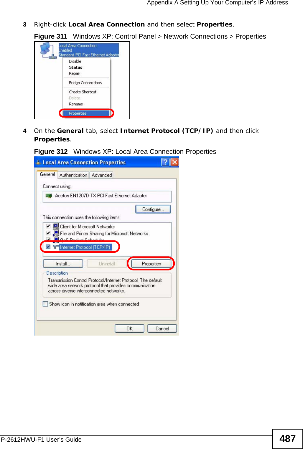
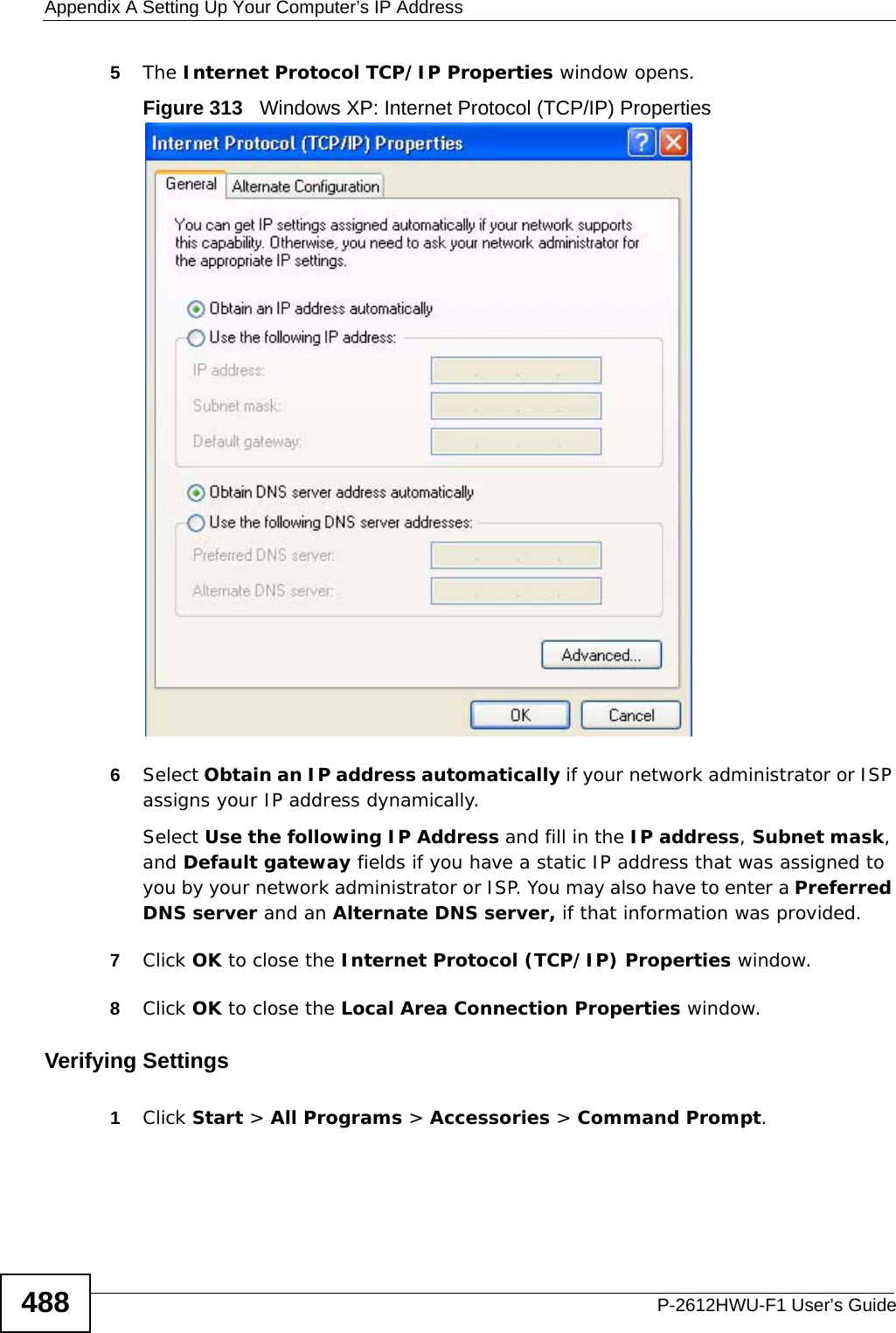
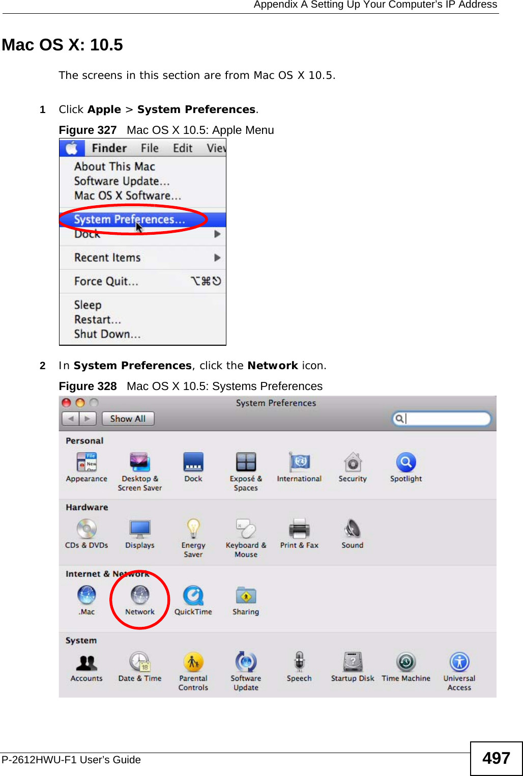
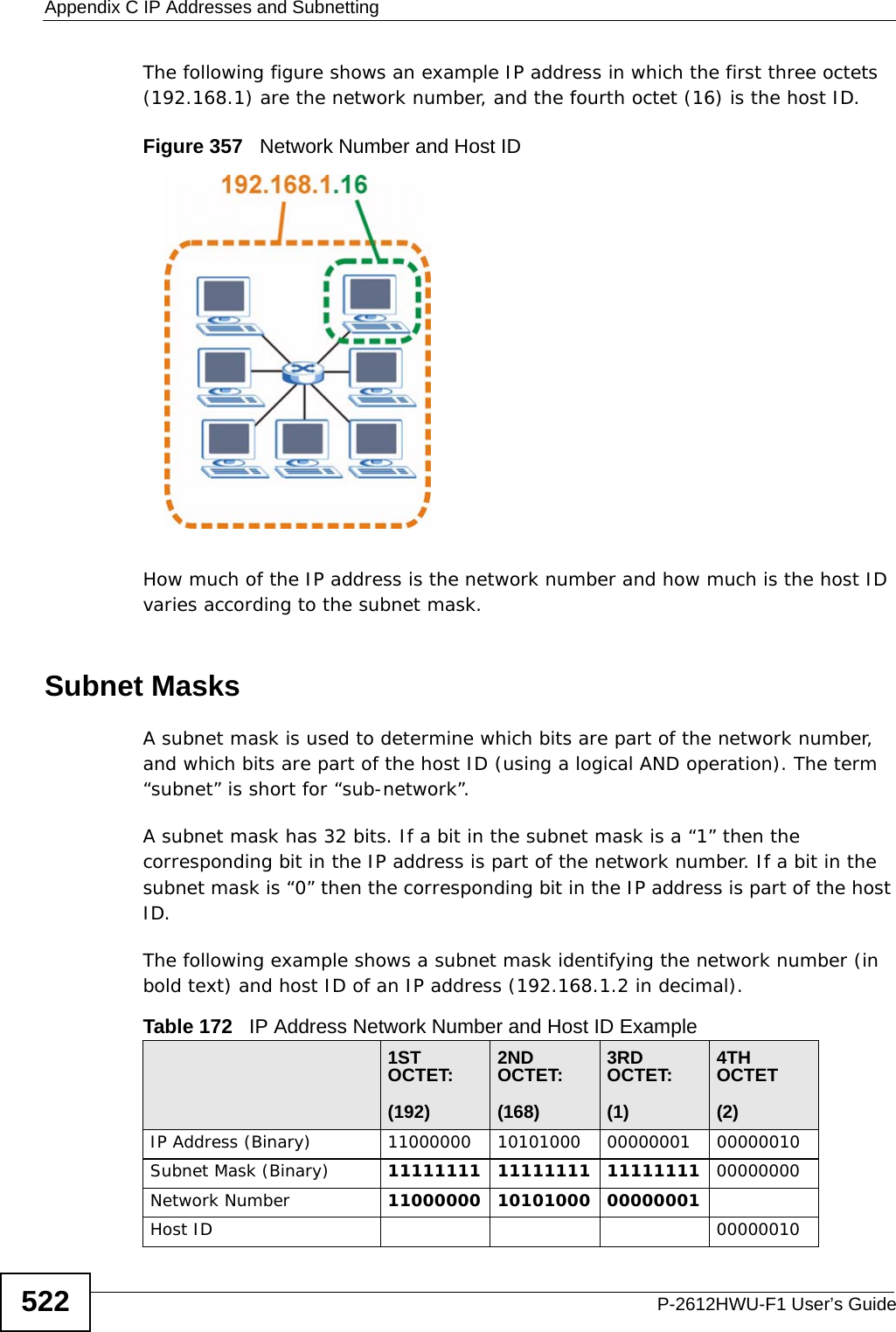
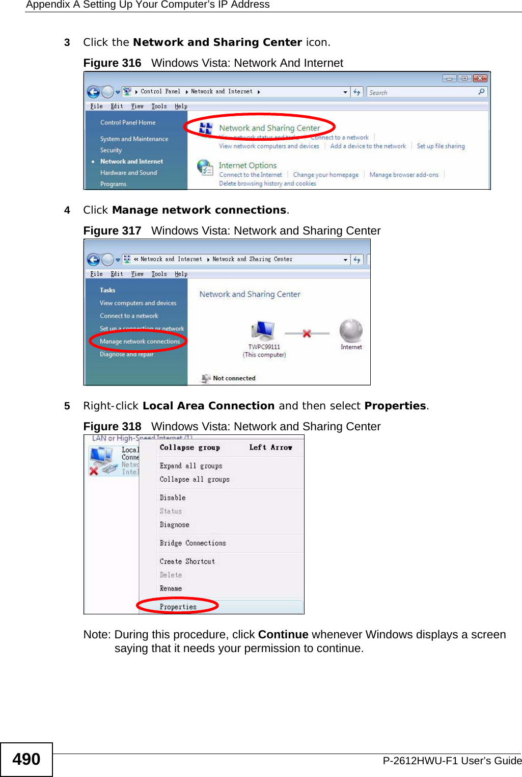
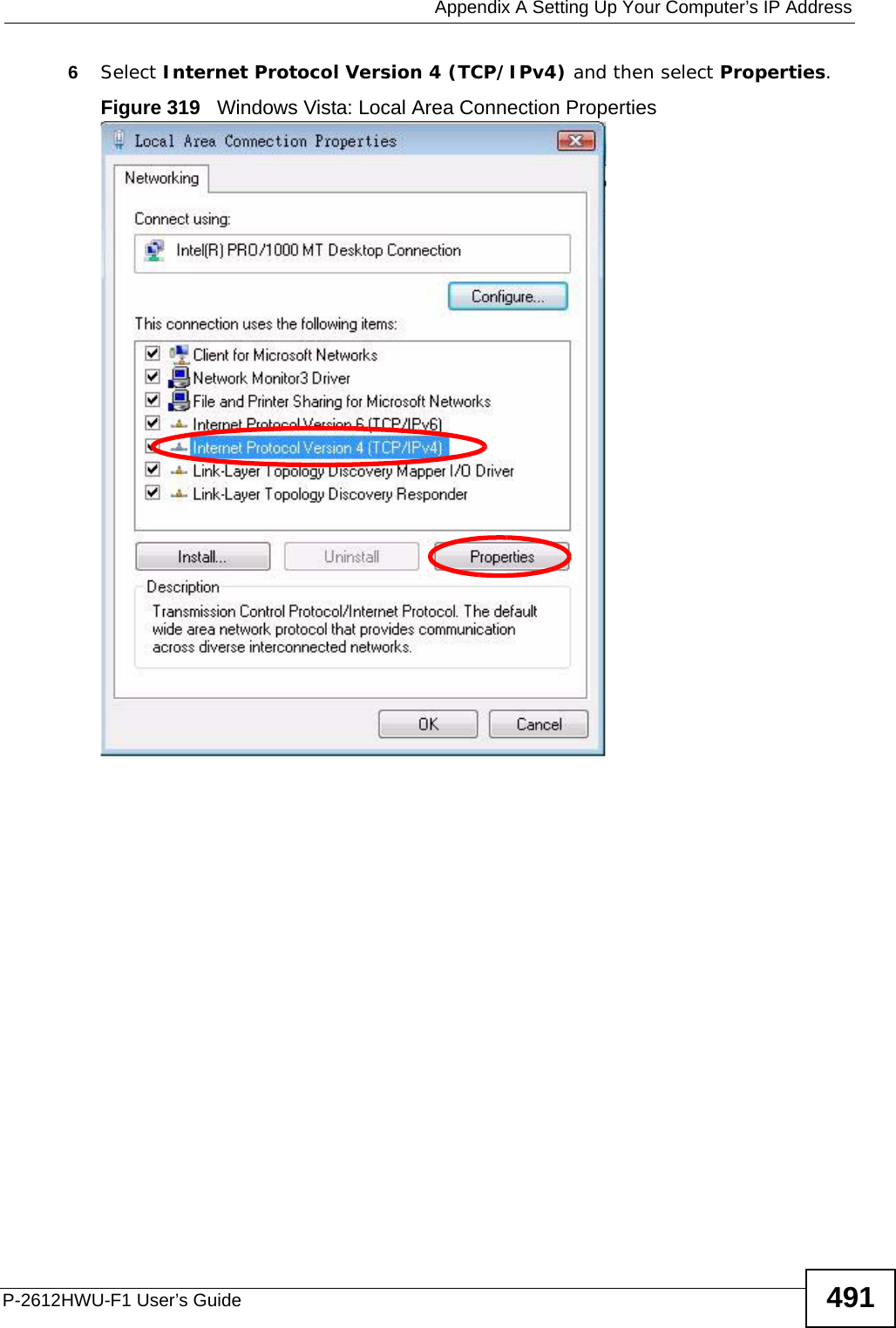
![Appendix A Setting Up Your Computer’s IP AddressP-2612HWU-F1 User’s Guide 4892In the Command Prompt window, type "ipconfig" and then press [ENTER]. You can also go to Start > Control Panel > Network Connections, right-click a network connection, click Status and then click the Support tab to view your IP address and connection information.Windows VistaThis section shows screens from Windows Vista Professional.1Click Start > Control Panel.Figure 314 Windows Vista: Start Menu2In the Control Panel, click the Network and Internet icon.Figure 315 Windows Vista: Control Panel](https://usermanual.wiki/ZyXEL-Communications/P2612HWUFX.Usermanual-part-4/User-Guide-1154267-Page-39.png)
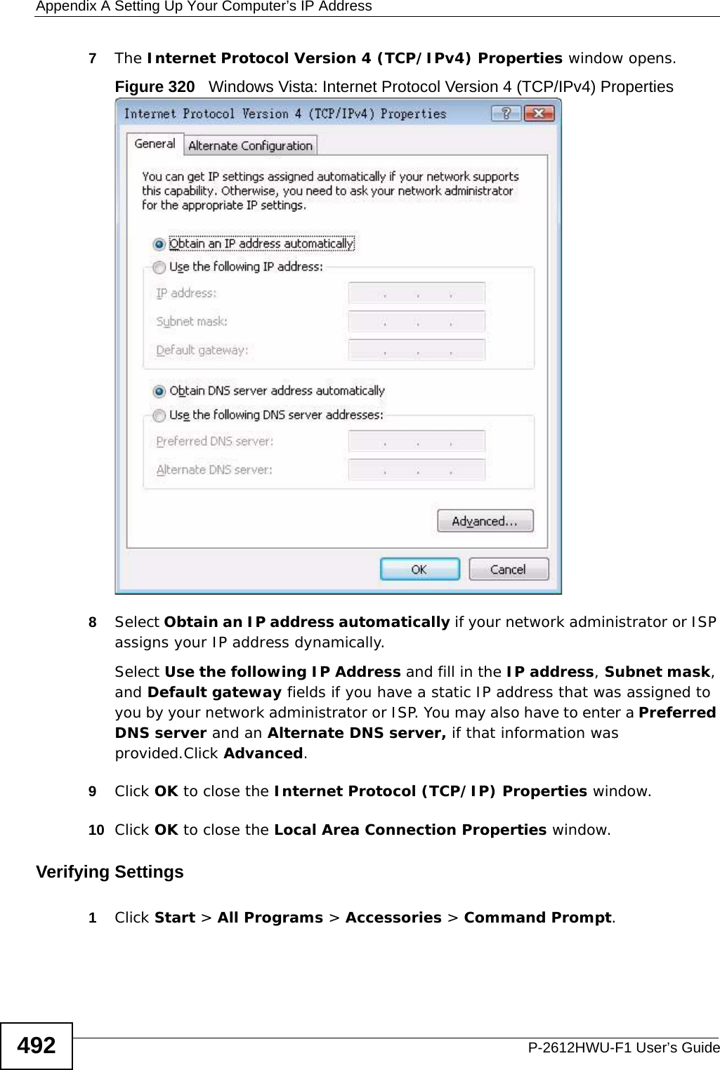
![Appendix A Setting Up Your Computer’s IP AddressP-2612HWU-F1 User’s Guide 4932In the Command Prompt window, type "ipconfig" and then press [ENTER]. You can also go to Start > Control Panel > Network Connections, right-click a network connection, click Status and then click the Support tab to view your IP address and connection information.Mac OS X: 10.3 and 10.4The screens in this section are from Mac OS X 10.4 but can also apply to 10.3.1Click Apple > System Preferences.Figure 321 Mac OS X 10.4: Apple Menu](https://usermanual.wiki/ZyXEL-Communications/P2612HWUFX.Usermanual-part-4/User-Guide-1154267-Page-43.png)