ZyXEL Communications P2612HWUFX Dual WAN ADSL2+ VoIP IAD User Manual SMG 700 User s Guide V1 00 Nov 2004
ZyXEL Communications Corporation Dual WAN ADSL2+ VoIP IAD SMG 700 User s Guide V1 00 Nov 2004
Contents
- 1. manual part 3
- 2. Usermanual part 1
- 3. Usermanual part 2
- 4. Usermanual part 4
Usermanual part 4
Chapter 27 Tools
P-2612HWU-F1 User’s Guide 451
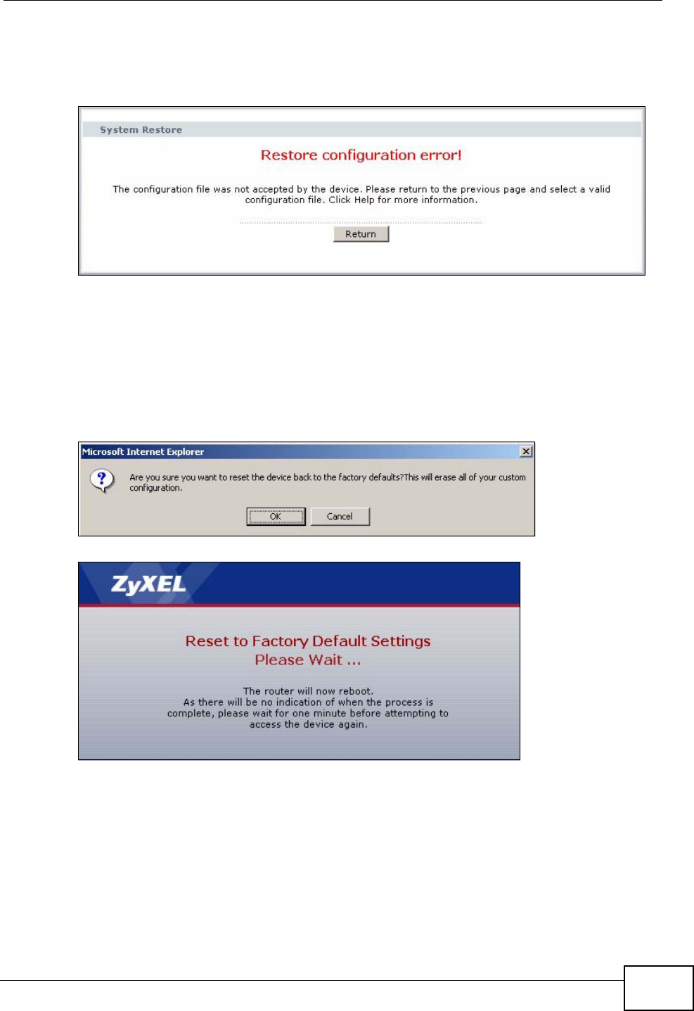
If the upload was not successful, the following screen will appear. Click Return to
go back to the Configuration screen.
Figure 295 Configuration Upload Error
27.3.1 Reset to Factory Defaults
Click the Reset button to clear all user-entered configuration information and
return the ZyXEL Device to its factory defaults. The following warning screen
appears.
Figure 296 Reset Warning Message
Figure 297 Reset In Process Message
You can also press the RESET button on the rear panel to reset the factory
defaults of your ZyXEL Device. Refer to Section 1.5 on page 30 for more
information on the RESET button.
Chapter 27 Tools
P-2612HWU-F1 User’s Guide
452
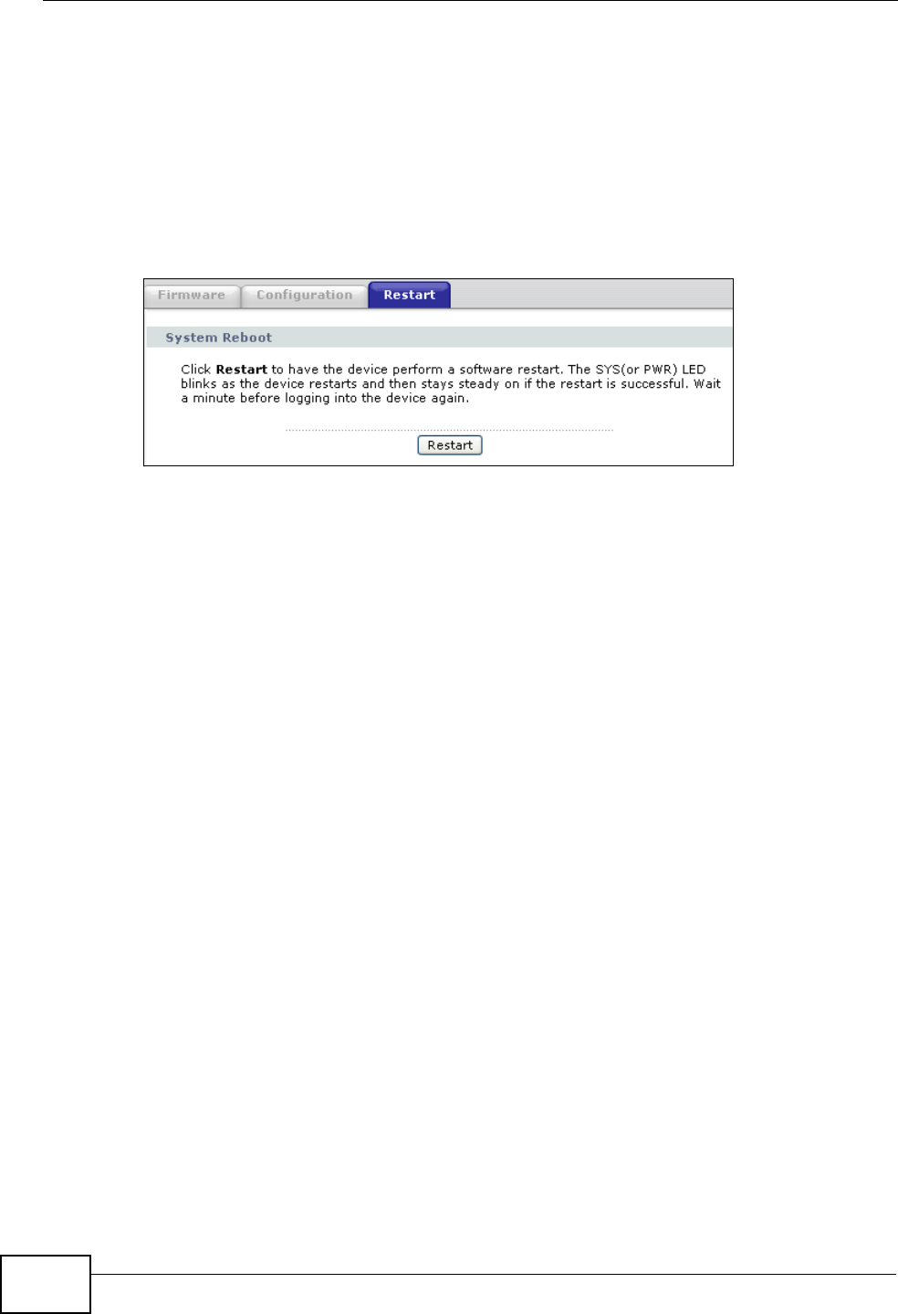
27.4 Restart
System restart allows you to reboot the ZyXEL Device without turning the power
off.
Click Maintenance > Tools > Restart. Click Restart to have the ZyXEL Device
reboot. This does not affect the ZyXEL Device's configuration.
Figure 298 Maintenance > Tools > Restart Screen
27.5 Using FTP or TFTP to Back Up
Configuration
This section covers how to use FTP or TFTP to save your device’s configuration file
to your computer.
27.5.1 Using the FTP Commands to Back Up Configuration
1Launch the FTP client on your computer.
2Enter “open”, followed by a space and the IP address of your ZyXEL Device.
3Enter your username as requested (the default is “admin”).
4Press [ENTER] when prompted for a password.
5Enter “bin” to set transfer mode to binary.
6Use “get” to transfer files from the ZyXEL Device to the computer, for example,
“get rom-0 config.rom” transfers the configuration file on the ZyXEL Device to
your computer and renames it “config.rom”. See earlier in this chapter for more
information on filename conventions.
7Enter “quit” to exit the ftp prompt.

Chapter 27 Tools
P-2612HWU-F1 User’s Guide 453
27.5.2 FTP Command Configuration Backup Example
This figure gives an example of using FTP commands from the DOS command
prompt to save your device’s configuration onto your computer.
Figure 299 FTP Session Example
27.5.3 Configuration Backup Using GUI-based FTP Clients
The following table describes some of the commands that you may see in GUI-
based FTP clients.
27.5.4 Backup Configuration Using TFTP
The ZyXEL Device supports the up/downloading of the firmware and the
configuration file using TFTP (Trivial File Transfer Protocol) over LAN. Although
TFTP should work over WAN as well, it is not recommended.
331 Enter PASS command
Password:
230 Logged in
ftp> bin
200 Type I OK
ftp> get rom-0 zyxel.rom
200 Port command okay
150 Opening data connection for STOR ras
226 File received OK
ftp: 16384 bytes sent in 1.10Seconds 297.89Kbytes/sec.
ftp> quit
Table 163 General Commands for GUI-based FTP Clients
COMMAND DESCRIPTION
Host Address Enter the address of the host server.
Login Type Anonymous.
This is when a user I.D. and password is automatically supplied
to the server for anonymous access. Anonymous logins will work
only if your ISP or service administrator has enabled this option.
Normal.
The server requires a unique User ID and Password to login.
Transfer Type Transfer files in either ASCII (plain text format) or in binary
mode.
Initial Remote
Directory Specify the default remote directory (path).
Initial Local Directory Specify the default local directory (path).

Chapter 27 Tools
P-2612HWU-F1 User’s Guide
454
To use TFTP, your computer must have both telnet and TFTP clients. To backup the
configuration file, follow the procedure shown next.
1Use telnet from your computer to connect to the ZyXEL Device and log in. Because
TFTP does not have any security checks, the ZyXEL Device records the IP address
of the telnet client and accepts TFTP requests only from this address.
2Enter command “sys stdio 0” to disable the management idle timeout, so the
TFTP transfer will not be interrupted. Enter command “sys stdio 5” to restore
the five-minute management idle timeout (default) when the file transfer is
complete.
3Launch the TFTP client on your computer and connect to the ZyXEL Device. Set
the transfer mode to binary before starting data transfer.
4Use the TFTP client (see the example below) to transfer files between the ZyXEL
Device and the computer. The file name for the configuration file is “rom-0” (rom-
zero, not capital o).
Note that the telnet connection must be active before and during the TFTP
transfer. For details on TFTP commands (see following example), please consult
the documentation of your TFTP client program. For UNIX, use “get” to transfer
from the ZyXEL Device to the computer and “binary” to set binary transfer mode.
27.5.5 TFTP Command Configuration Backup Example
The following is an example TFTP command:
tftp [-i] host get rom-0 config.rom
where “i” specifies binary image transfer mode (use this mode when transferring
binary files), “host” is the ZyXEL Device IP address, “get” transfers the file source
on the ZyXEL Device (rom-0, name of the configuration file on the ZyXEL Device)
to the file destination on the computer and renames it config.rom.

Chapter 27 Tools
P-2612HWU-F1 User’s Guide 455
27.5.6 Configuration Backup Using GUI-based TFTP Clients
The following table describes some of the fields that you may see in GUI-based
TFTP clients.
Refer to Section on page 440 to read about configurations that disallow TFTP and
FTP over WAN.
27.6 Using FTP or TFTP to Restore Configuration
This section shows you how to restore a previously saved configuration. Note that
this function erases the current configuration before restoring a previous back up
configuration; please do not attempt to restore unless you have a backup
configuration file stored on disk.
FTP is the preferred method for restoring your current computer configuration to
your device since FTP is faster. Please note that you must wait for the system to
automatically restart after the file transfer is complete.
Do not interrupt the file transfer process as this may
PERMANENTLY DAMAGE your device. When the Restore
Configuration process is complete, the device automatically
restarts.
Table 164 General Commands for GUI-based TFTP Clients
COMMAN
DDESCRIPTION
Host Enter the IP address of the ZyXEL Device. 192.168.1.1 is the ZyXEL Device’s
default IP address when shipped.
Send/
Fetch Use “Send” to upload the file to the ZyXEL Device and “Fetch” to back up the
file on your computer.
Local File Enter the path and name of the firmware file (*.bin extension) or
configuration file (*.rom extension) on your computer.
Remote
File This is the filename on the ZyXEL Device. The filename for the firmware is
“ras” and for the configuration file, is “rom-0”.
Binary Transfer the file in binary mode.
Abort Stop transfer of the file.

Chapter 27 Tools
P-2612HWU-F1 User’s Guide
456
27.6.1 Restore Using FTP Session Example
Figure 300 Restore Using FTP Session Example
Refer to Section on page 440 to read about configurations that disallow TFTP and
FTP over WAN.
27.7 FTP and TFTP Firmware and Configuration
File Uploads
This section shows you how to upload firmware and configuration files.
Do not interrupt the file transfer process as this may
PERMANENTLY DAMAGE your device.
FTP is the preferred method for uploading the firmware and configuration. To use
this feature, your computer must have an FTP client. The following sections give
examples of how to upload the firmware and the configuration files.
27.7.1 FTP File Upload Command from the DOS Prompt
Example
1Launch the FTP client on your computer.
2Enter “open”, followed by a space and the IP address of your device.
3Enter your username as requested (the default is “admin”).
4Press [ENTER] when prompted for a password.
5Enter “bin” to set transfer mode to binary.
ftp> put config.rom rom-0
200 Port command okay
150 Opening data connection for STOR rom-0
226 File received OK
221 Goodbye for writing flash
ftp: 16384 bytes sent in 0.06Seconds 273.07Kbytes/sec.
ftp>quit

Chapter 27 Tools
P-2612HWU-F1 User’s Guide 457
6Use “put” to transfer files from the computer to the device, for example, “put
firmware.bin ras” transfers the firmware on your computer (firmware.bin) to the
device and renames it “ras”. Similarly, “put config.rom rom-0” transfers the
configuration file on your computer (config.rom) to the device and renames it
“rom-0”. Likewise “get rom-0 config.rom” transfers the configuration file on the
device to your computer and renames it “config.rom.” See earlier in this chapter
for more information on filename conventions.
7Enter “quit” to exit the ftp prompt.
27.7.2 FTP Session Example of Firmware File Upload
Figure 301 FTP Session Example of Firmware File Upload
More commands (found in GUI-based FTP clients) are listed earlier in this chapter.
Refer to Section on page 440 to read about configurations that disallow TFTP and
FTP over WAN.
27.7.3 TFTP File Upload
The device also supports the uploading of firmware files using TFTP (Trivial File
Transfer Protocol) over LAN. Although TFTP should work over WAN as well, it is not
recommended.
To use TFTP, your computer must have both telnet and TFTP clients. To transfer
the firmware and the configuration file, follow the procedure shown next.
1Use telnet from your computer to connect to the device and log in. Because TFTP
does not have any security checks, the device records the IP address of the telnet
client and accepts TFTP requests only from this address.
331 Enter PASS command
Password:
230 Logged in
ftp> bin
200 Type I OK
ftp> put firmware.bin ras
200 Port command okay
150 Opening data connection for STOR ras
226 File received OK
ftp: 1103936 bytes sent in 1.10Seconds 297.89Kbytes/sec.
ftp> quit

Chapter 27 Tools
P-2612HWU-F1 User’s Guide
458
2Enter the command “sys stdio 0” to disable the management idle timeout, so the
TFTP transfer will not be interrupted. Enter “command sys stdio 5” to restore the
five-minute management idle timeout (default) when the file transfer is complete.
3Launch the TFTP client on your computer and connect to the device. Set the
transfer mode to binary before starting data transfer.
4Use the TFTP client (see the example below) to transfer files between the device
and the computer. The file name for the firmware is “ras”.
Note that the telnet connection must be active and the device in CI mode before
and during the TFTP transfer. For details on TFTP commands (see following
example), please consult the documentation of your TFTP client program. For
UNIX, use “get” to transfer from the device to the computer, “put” the other way
around, and “binary” to set binary transfer mode.
27.7.4 TFTP Upload Command Example
The following is an example TFTP command:
tftp [-i] host put firmware.bin ras
Where “i” specifies binary image transfer mode (use this mode when transferring
binary files), “host” is the device’s IP address, “put” transfers the file source on
the computer (firmware.bin – name of the firmware on the computer) to the file
destination on the remote host (ras - name of the firmware on the device).
Commands that you may see in GUI-based TFTP clients are listed earlier in this
chapter.
P-2612HWU-F1 User’s Guide 459
CHAPTER 28
Diagnostic
28.1 Overview
These read-only screens display information to help you identify problems with the
ZyXEL Device.
28.1.1 What You Can Do in the Diagnostic Screens
Use the General Diagnostic screen (Section 28.2 on page 459) to ping an IP
address.
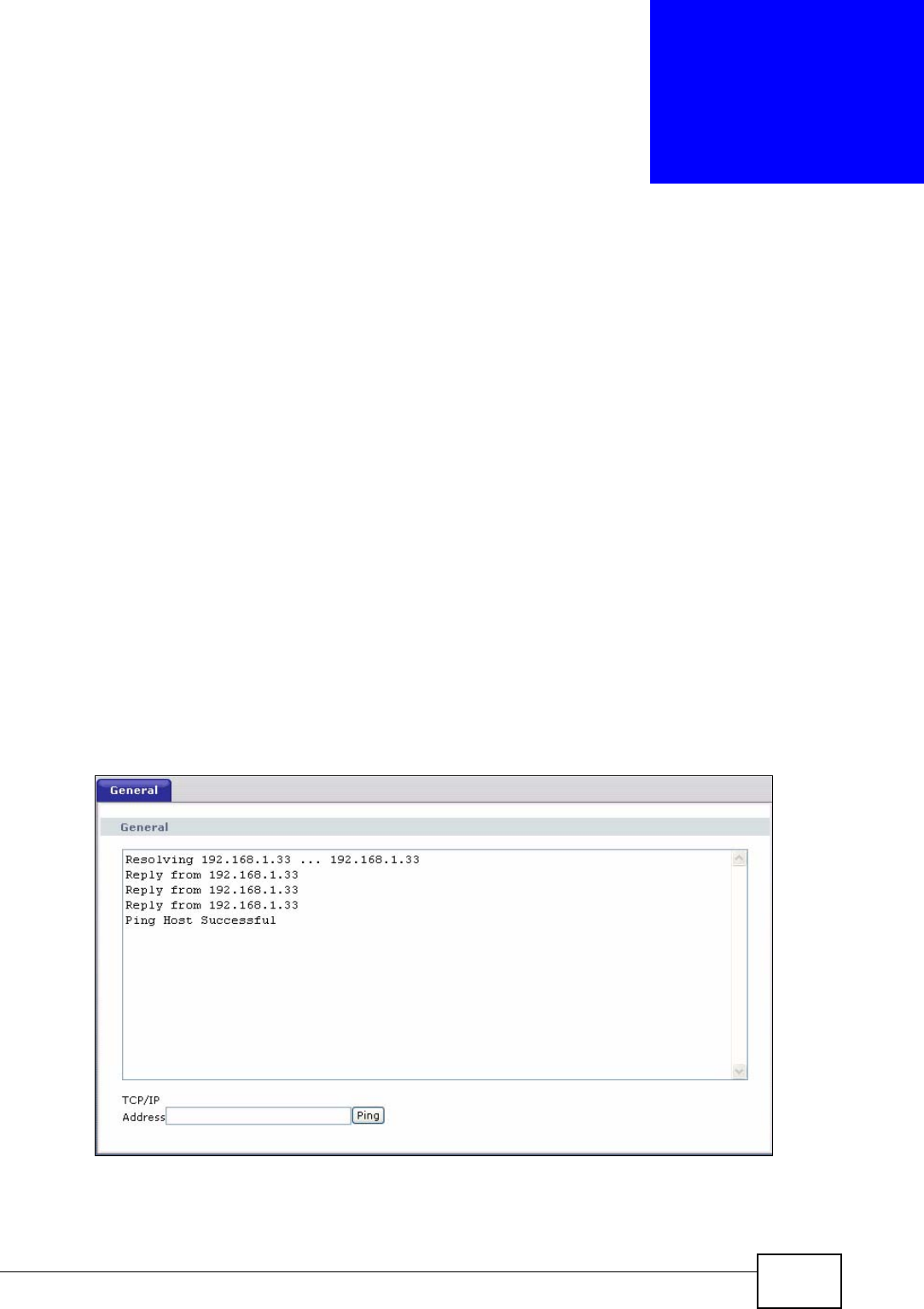
28.2 The General Diagnostic Screen
Click Maintenance > Diagnostic to open the screen shown next.
Figure 302 Maintenance > Diagnostic > General

Chapter 28 Diagnostic
P-2612HWU-F1 User’s Guide
460
The following table describes the fields in this screen.
Table 165 Maintenance > Diagnostic > General
LABEL DESCRIPTION
TCP/IP
Address Type the IP address of a computer that you want to ping in order to test a
connection.
Ping Click this button to ping the IP address that you entered.

P-2612HWU-F1 User’s Guide 461
CHAPTER 29
Troubleshooting
29.1 Overview
This chapter offers some suggestions to solve problems you might encounter. The
potential problems are divided into the following categories.
•Power, Hardware Connections, and LEDs
•ZyXEL Device Access and Login
•Internet Access
•Phone Calls and VoIP
•Multiple SIP Accounts
•USB Device Connection
29.2 Power, Hardware Connections, and LEDs
The ZyXEL Device does not turn on. None of the LEDs turn on.
1Make sure the ZyXEL Device is turned on.
2Make sure you are using the power adaptor or cord included with the ZyXEL
Device.
3Make sure the power adaptor or cord is connected to the ZyXEL Device and
plugged in to an appropriate power source. Make sure the power source is turned
on.
4Turn the ZyXEL Device off and on.
5If the problem continues, contact the vendor.

Chapter 29 Troubleshooting
P-2612HWU-F1 User’s Guide
462
One of the LEDs does not behave as expected.
1Make sure you understand the normal behavior of the LED. See Section 1.4 on
page 28.
2Check the hardware connections. See the Quick Start Guide.
3Inspect your cables for damage. Contact the vendor to replace any damaged
cables.
4Turn the ZyXEL Device off and on.
5If the problem continues, contact the vendor.
29.3 ZyXEL Device Access and Login
I forgot the IP address for the ZyXEL Device.
1The default IP address is 192.168.1.1.
2If you changed the IP address and have forgotten it, you might get the IP address
of the ZyXEL Device by looking up the IP address of the default gateway for your
computer. To do this in most Windows computers, click Start > Run, enter cmd,
and then enter ipconfig. The IP address of the Default Gateway might be the IP
address of the ZyXEL Device (it depends on the network), so enter this IP address
in your Internet browser.
3If this does not work, you have to reset the device to its factory defaults. See
Section 1.5 on page 30.
I cannot see or access the Login screen in the web configurator.
1Make sure you are using the correct IP address.
• The default IP address is 192.168.1.1.
• If you changed the IP address (Section on page 127), use the new IP
address.

Chapter 29 Troubleshooting
P-2612HWU-F1 User’s Guide 463
• If you changed the IP address and have forgotten it, see the troubleshooting
suggestions for I forgot the IP address for the ZyXEL Device.
2Check the hardware connections, and make sure the LEDs are behaving as
expected. See the Quick Start Guide.
3Make sure your Internet browser does not block pop-up windows and has
JavaScripts and Java enabled. See Appendix B on page 511.
4If you disabled Any IP (Section 7.2.1 on page 120), make sure your computer is
in the same subnet as the ZyXEL Device. (If you know that there are routers
between your computer and the ZyXEL Device, skip this step.)
• If there is a DHCP server on your network, make sure your computer is using
a dynamic IP address. See Appendix A on page 485. Your ZyXEL Device is a
DHCP server by default.
• If there is no DHCP server on your network, make sure your computer’s IP
address is in the same subnet as the ZyXEL Device. See Appendix A on page
485.
5Reset the device to its factory defaults, and try to access the ZyXEL Device with
the default IP address. See Section 1.5 on page 30.
6If the problem continues, contact the network administrator or vendor, or try one
of the advanced suggestions.
Advanced Suggestions
• Try to access the ZyXEL Device using another service, such as Telnet. If you can
access the ZyXEL Device, check the remote management settings and firewall
rules to find out why the ZyXEL Device does not respond to HTTP.
• If your computer is connected to the WAN port or is connected wirelessly, use a
computer that is connected to a ETHERNET port.
I can see the Login screen, but I cannot log in to the ZyXEL Device.
1Make sure you have entered the user name and password correctly. The default
user name is admin. These fields are case-sensitive, so make sure [Caps Lock] is
not on.
2You cannot log in to the web configurator while someone is using Telnet to access
the ZyXEL Device. Log out of the ZyXEL Device in the other session, or ask the
person who is logged in to log out.
3Turn the ZyXEL Device off and on.

Chapter 29 Troubleshooting
P-2612HWU-F1 User’s Guide
464
4If this does not work, you have to reset the device to its factory defaults. See
Section 29.2 on page 461.
I cannot Telnet to the ZyXEL Device.
See the troubleshooting suggestions for I cannot see or access the Login screen in
the web configurator. Ignore the suggestions about your browser.
I cannot use FTP to upload / download the configuration file. / I cannot use FTP to
upload new firmware.
See the troubleshooting suggestions for I cannot see or access the Login screen in
the web configurator. Ignore the suggestions about your browser.
29.4 Internet Access
I cannot access the Internet.
1Check the hardware connections, and make sure the LEDs are behaving as
expected. See the Quick Start Guide and Section 1.4 on page 28.
2Make sure you entered your ISP account information correctly in the wizard. These
fields are case-sensitive, so make sure [Caps Lock] is not on.
3If you are trying to access the Internet wirelessly, make sure the wireless settings
in the wireless client are the same as the settings in the AP.
4Disconnect all the cables from your device, and follow the directions in the Quick
Start Guide again.
5If the problem continues, contact your ISP.
I cannot access the Internet anymore. I had access to the Internet (with the ZyXEL
Device), but my Internet connection is not available anymore.

Chapter 29 Troubleshooting
P-2612HWU-F1 User’s Guide 465
1Check the hardware connections, and make sure the LEDs are behaving as
expected. See the Quick Start Guide and Section 1.4 on page 28.
2Turn the ZyXEL Device off and on.
3If the problem continues, contact your ISP.
The Internet connection is slow or intermittent.
1There might be a lot of traffic on the network. Look at the LEDs, and check Section
1.4 on page 28. If the ZyXEL Device is sending or receiving a lot of information,
try closing some programs that use the Internet, especially peer-to-peer
applications.
2Check the signal strength. If the signal strength is low, try moving the ZyXEL
Device closer to the AP if possible, and look around to see if there are any devices
that might be interfering with the wireless network (for example, microwaves,
other wireless networks, and so on).
3Turn the ZyXEL Device off and on.
4If the problem continues, contact the network administrator or vendor, or try one
of the advanced suggestions.
Advanced Suggestions
• Check the settings for bandwidth management. If it is disabled, you might
consider activating it. If it is enabled, you might consider changing the
allocations.
• Check the settings for QoS. If it is disabled, you might consider activating it. If it
is enabled, you might consider raising or lowering the priority for some
applications.
29.5 Phone Calls and VoIP
The telephone port won’t work or the telephone lacks a dial tone.
1Check the telephone connections and telephone wire.

Chapter 29 Troubleshooting
P-2612HWU-F1 User’s Guide
466
I can access the Internet, but cannot make VoIP calls.
1The PHONE light should come on. Make sure that your telephone is connected to
the PHONE port.
2You can also check the VoIP status in the Status screen.
3If the VoIP settings are correct, use speed dial to make peer-to-peer calls. If you
can make a call using speed dial, there may be something wrong with the SIP
server, contact your VoIP service provider.
29.6 Multiple SIP Accounts
You can set up two SIP accounts on your ZyXEL Device and your ZyXEL Device is
equipped with two phone ports. By default your ZyXEL Device uses SIP account 1
with both phone ports for outgoing calls, and it uses SIP accounts 1 and 2 for
incoming calls. With this setting, you always use SIP account 1 for your outgoing
calls and you cannot distinguish which SIP account the calls are coming in
through. If you want to control the use of different dialing plans for accounting
purposes or other reasons, you need to configure your phone ports in order to
control which SIP account you are using when placing or receiving calls.
Chapter 29 Troubleshooting
P-2612HWU-F1 User’s Guide 467
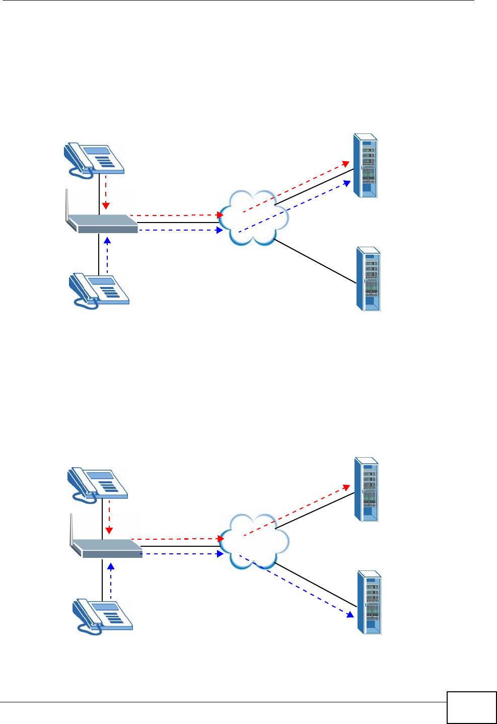
29.6.1 Outgoing Calls
The following figure represents the default behavior of your ZyXEL Device when
two SIP accounts are configured and you are using two phones. When you place a
call from phone port 1 or phone port 2, the ZyXEL Device will use SIP account 1.
Figure 303 Outgoing Calls: Default
In the next example, phone port 1 is configured to use SIP account 1 and phone
port 2 is configured to use SIP account 2. In this case, every time you place a call
through phone port 1, you are using your SIP account 1. Similarly, every time you
place a call through phone port 2, you are using your SIP account 2. To apply
these configuration changes you need to configure the Analog Phone screen. See
Section 10.5 on page 190.
Figure 304 Outgoing Calls: Individual Configuration
PHONE 1
Internet SIP 1
SIP 2
PHONE 2
Internet SIP 1
SIP 2
PHONE 1
PHONE 2
Chapter 29 Troubleshooting
P-2612HWU-F1 User’s Guide
468
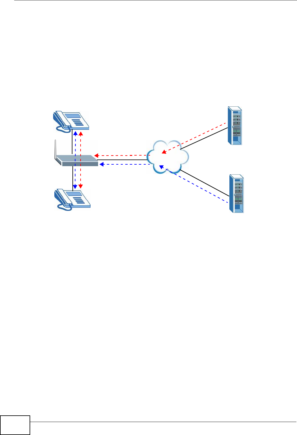
29.6.2 Incoming Calls
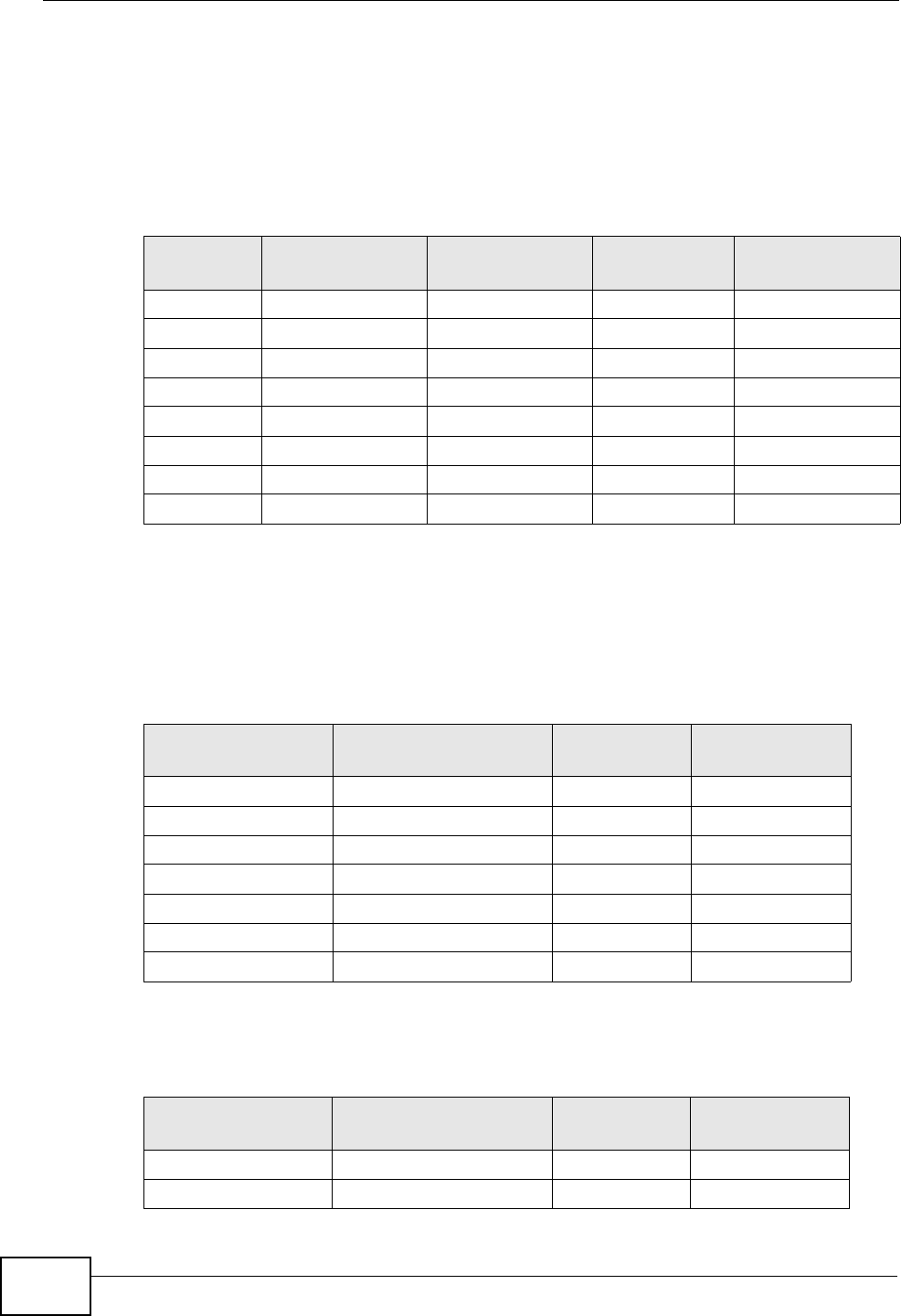
The following example shows the default behavior of your ZyXEL Device for
incoming calls when two SIP accounts are configured and you are using two
phones. When a call comes in from your SIP account 1, the phones connected to
both phone port 1 and phone port 2 ring. Similarly, when a call comes in from your
SIP account 2, the phones connected to both phone port 1 and phone port 2 ring.
In either case you are not sure which SIP account the call is coming from.
Figure 305 Incoming Calls: Default
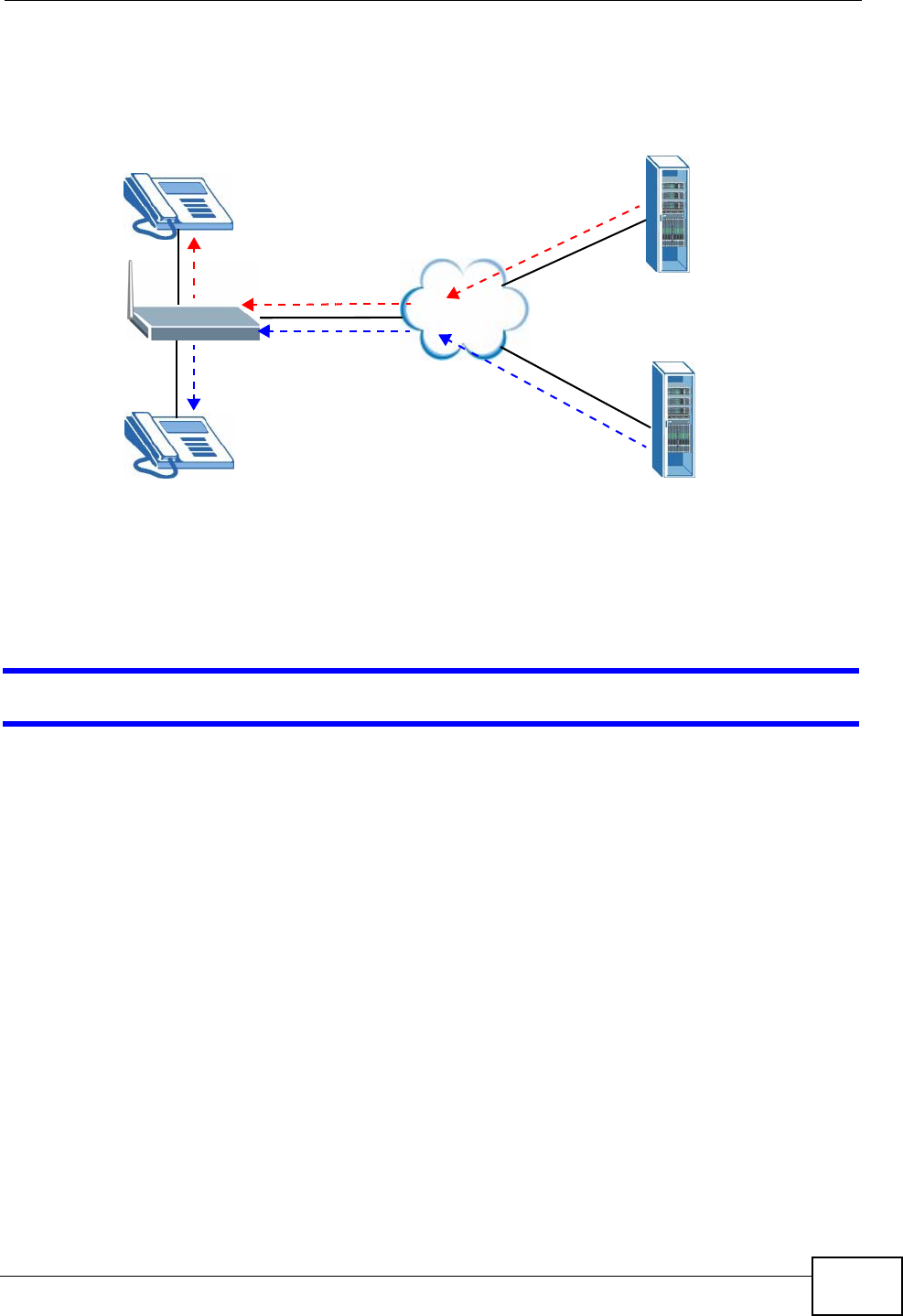
In the next example, phone port 1 is configured to use SIP account 1 and phone
port 2 is configured to use SIP account 2 for incoming calls. In this case, every
time you receive a call from your SIP account 1, the phone connected to phone
port 1 rings. Similarly, every time you receive a call from your SIP account 2,
Internet SIP 1
SIP 2
PHONE 1
PHONE 2
Chapter 29 Troubleshooting
P-2612HWU-F1 User’s Guide 469
phone port 2 rings. To apply these configuration changes you need to configure
the Analog Phone screen. See Section 10.5 on page 190.
Figure 306 Incoming Calls: Individual Configuration
29.7 USB Device Connection
The ZyXEL Device fails to detect my USB device.
1Disconnect the USB device.
2Reboot the ZyXEL Device.
3If you are connecting a USB hard drive that comes with an external power supply,
make sure it is connected to an appropriate power source that is on.
4Re-connect your USB device to the ZyXEL Device.
Internet SIP 1
SIP 2
PHONE 1
PHONE 2

Chapter 29 Troubleshooting
P-2612HWU-F1 User’s Guide
470

P-2612HWU-F1 User’s Guide 471
CHAPTER 30
Product Specifications
The following tables summarize the ZyXEL Device’s hardware and firmware
features.
Hardware Specifications
Table 166 Hardware Specifications
Dimensions (218 W) x (144 D) x (40 H) mm
Weight 460 g
Power Specification 18V 1A DC
Built-in Switch Four auto-negotiating, auto MDI/MDI-X 10/100 Mbps RJ-45
Ethernet ports
DSL Port One RJ11 DSL port
WAN Port One RJ45 WAN port
PHONE Ports 2 RJ-11 FXS POTS ports
RESET Button Restores factory defaults
WLAN Button 1 second: Turn on or off WLAN
5 seconds: Start WPS
USB Port One USB v2.0 port for file sharing or print server setup
Antenna One attached external dipole antenna, 2.9 dBi
Operation
Temperature 0º C ~ 40º C
Storage Temperature -20º ~ 60º C
Operation Humidity 20% ~ 85% RH
Storage Humidity 20% ~ 90% RH
Distance between the
centers of the holes
(for wall-mounting)
on the device’s back
137.20mm
Screw size for wall-
mounting M4 tap

Chapter 30 Product Specifications
P-2612HWU-F1 User’s Guide
472
Firmware Specifications
Table 167 Firmware Specifications
Default IP Address 192.168.1.1
Default Subnet Mask 255.255.255.0 (24 bits)
Default User Name adminpldt
Default Password 1234567890
DHCP Server IP Pool Starting Address: 192.168.1.33
Size: 32
Static DHCP
Addresses 10
Content Filtering Web page blocking by URL keyword.
Static Routes 16
Device Management Use the web configurator to easily configure the rich range of
features on the ZyXEL Device.
Wireless
Functionality
(wireless devices
only)
Allow the IEEE 802.11b and/or IEEE 802.11g wireless clients to
connect to the ZyXEL Device wirelessly. Enable wireless security
(WEP, WPA(2), WPA(2)-PSK) and/or MAC filtering to protect your
wireless network.
Firmware Upgrade Download new firmware (when available) from the ZyXEL web site
and use the web configurator, an FTP or a TFTP tool to put it on
the ZyXEL Device.
Note: Only upload firmware for your specific model!
Configuration Backup
& Restoration Make a copy of the ZyXEL Device’s configuration. You can put it
back on the ZyXEL Device later if you decide to revert back to an
earlier configuration.
Network Address
Translation (NAT) Each computer on your network must have its own unique IP
address. Use NAT to convert your public IP address(es) to multiple
private IP addresses for the computers on your network.
Port Forwarding If you have a server (mail or web server for example) on your
network, you can use this feature to let people access it from the
Internet.
IEEE 802.1Q and
IEEE 802.1P Use IEEE 802.1Q VLAN and IEEE 802.1P priority tags in
implementing QoS. Configure VLANs based on port, PVC, and
SSID. Specify a PVID to assign to untagged frames or priority-
tagged frames received on this port, SSID, or PVC. Assign a
priority for the traffic transmitted through a port, SSID, or PVC.
DHCP (Dynamic Host
Configuration
Protocol)
Use this feature to have the ZyXEL Device assign IP addresses, an
IP default gateway and DNS servers to computers on your
network. Your device can also act as a surrogate DHCP server
(DHCP Relay) where it relays IP address assignment from the
actual real DHCP server to the clients.

Chapter 30 Product Specifications
P-2612HWU-F1 User’s Guide 473
Dynamic DNS
Support With Dynamic DNS (Domain Name System) support, you can use
a fixed URL, www.zyxel.com for example, with a dynamic IP
address. You must register for this service with a Dynamic DNS
service provider.
IP Multicast IP multicast is used to send traffic to a specific group of
computers. The ZyXEL Device supports versions 1 and 2 of IGMP
(Internet Group Management Protocol) used to join multicast
groups (see RFC 2236).
Time and Date Get the current time and date from an external server when you
turn on your ZyXEL Device. You can also set the time manually.
These dates and times are then used in logs.
Logs Use logs for troubleshooting. You can send logs from the ZyXEL
Device to an external syslog server.
Universal Plug and
Play (UPnP) A UPnP-enabled device can dynamically join a network, obtain an
IP address and convey its capabilities to other devices on the
network.
Firewall Your device has a stateful inspection firewall with DoS (Denial of
Service) protection. By default, when the firewall is activated, all
incoming traffic from the WAN to the LAN is blocked unless it is
initiated from the LAN. The firewall supports TCP/UDP inspection,
DoS detection and prevention, real time alerts, reports and logs.
Content Filtering Content filtering allows you to block access to Internet web sites
that contain key words (that you specify) in the URL. You can also
schedule when to perform the filtering and give trusted LAN IP
addresses unfiltered Internet access.
QoS (Quality of
Service) You can efficiently manage traffic on your network by reserving
bandwidth and giving priority to certain types of traffic and/or to
particular computers.
Remote Management This allows you to decide whether a service (HTTP or FTP traffic for
example) from a computer on a network (LAN or WAN for
example) can access the ZyXEL Device.
Any IP The Any IP feature allows a computer to access the Internet and
the ZyXEL Device without changing the network settings (such as
IP address and subnet mask) of the computer, when the IP
addresses of the computer and the ZyXEL Device are not in the
same subnet.
PPPoE Support
(RFC2516) PPPoE (Point-to-Point Protocol over Ethernet) emulates a dial-up
connection. It allows your ISP to use their existing network
configuration with newer broadband technologies such as ADSL.
The PPPoE driver on your device is transparent to the computers
on the LAN, which see only Ethernet and are not aware of PPPoE
thus saving you from having to manage PPPoE clients on individual
computers.
IPSec VPN Capability Establish a Virtual Private Network (VPN) to connect with business
partners and branch offices using data encryption and the Internet
to provide secure communications without the expense of leased
site-to-site lines. The ZyXEL Device VPN is based on the IPSec
standard and is interoperable with other IPSec-based VPN
products.
The ZyXEL Device supports up to two simultaneous IPSec
connections.
Table 167 Firmware Specifications (continued)

Chapter 30 Product Specifications
P-2612HWU-F1 User’s Guide
474
Other PPPoE Features PPPoE idle time out
PPPoE dial on demand
Multiple PVC
(Permanent Virtual
Circuits) Support
Your device supports one Permanent Virtual Circuits (PVCs).
IP Alias IP alias allows you to partition a physical network into logical
networks over the same Ethernet interface. Your device supports
three logical LAN interfaces via its single physical Ethernet
interface with the your device itself as the gateway for each LAN
network.
Packet Filters Your device’s packet filtering function allows added network
security and management.
ADSL Standards Support ITU G.992.1 G.dmt
EOC specified in ITU-T G.992.1
ADSL2 G.dmt.bis (G.992.3)
ADSL2 G.lite.bis (G.992.4)
ADSL 2/2+ AnnexM
ADSL2+ (G.992.5)
Reach-Extended ADSL (RE ADSL)
SRA (Seamless Rate Adaptation)
Auto-negotiating rate adaptation
ADSL physical connection AAL5 (ATM Adaptation Layer type 5)
Multi-protocol over AAL5 (RFC 2684/1483)
PPP over ATM AAL5 (RFC 2364)
PPP over Ethernet (RFC 2516)
Multiple PPPoE
VC-based and LLC-based multiplexing
I.610 F4/F5 OAM
Table 167 Firmware Specifications (continued)

Chapter 30 Product Specifications
P-2612HWU-F1 User’s Guide 475
Voice Specifications
Note: To take full advantage of the supplementary phone services available through
the ZyXEL Device's phone port, you may need to subscribe to the services from
your VoIP service provider.
Note: Not all features are supported by all service providers. Consult your service
provider for more information.
Other Protocol
Support PPP (Point-to-Point Protocol) link layer protocol
Transparent bridging for unsupported network layer protocols
RIP I/RIP II
ICMP
ATM QoS
SNMP v1 and v2c with MIB II support (RFC 1213)
IP Multicasting IGMP v1 and v2
IGMP Proxy
Management Embedded Web Configurator
CLI (Command Line Interpreter)
SNMP v1 & v2c with MIB II
Embedded FTP/TFTP Server for firmware upgrade and
configuration file backup and restore
Telnet for remote management
Remote Management Control: Telnet, FTP, Web, SNMP and DNS.
Remote Firmware Upgrade
Syslog
Table 167 Firmware Specifications (continued)

Chapter 30 Product Specifications
P-2612HWU-F1 User’s Guide
476
Table 168 Voice Features
Call Park and
Pickup Call park and pickup lets you put a call on hold (park) and then
continue the call (pickup). The caller must still pay while the call is
parked.
When you park the call, you enter a number of your choice (up to
eight digits), which you must enter again when you pick up the call. If
you do not enter the correct number, you cannot pickup the call. This
means that only someone who knows the number you have chosen
can pick up the call.
You can have more than one call on hold at the same time, but you
must give each call a different number.
Call Return With call return, you can place a call to the last number that called
you (either answered or missed). The last incoming call can be
through either SIP or PSTN.
Country Code Phone standards and settings differ from one country to another, so
the settings on your ZyXEL Device must be configured to match those
of the country you are in. The country code feature allows you to do
this by selecting the country from a list rather than changing each
setting manually. Configure the country code feature when you move
the ZyXEL Device from one country to another.
Do not Disturb
(DnD) This feature allows you to set your phone not to ring when someone
calls you. You can set each phone independently using its keypad, or
configure global settings for all phones using the command line
interpreter.
Auto Dial You can set the ZyXEL Device to automatically dial a specified number
immediately whenever you lift a phone off the hook. Use the Web
Configurator to set the specified number. Use the command line
interpreter to have the ZyXEL Device wait a specified length of time
before dialing the number.
Phone config The phone config table allows you to customize the phone keypad
combinations you use to access certain features on the ZyXEL Device,
such as call waiting, call return, and call forward. The phone config
table is configurable in command interpreter mode.
HTTP pincode If your service provider uses an auto provisioning server, you need to
enter a personal identification number (supplied by your service
provider) before you first use the feature.
Firmware update
enable / disable If your service provider uses this feature, you hear a recorded
message when you pick up the phone when new firmware is available
for your ZyXEL Device. Enter *99# in your phone’s keypad to have
the ZyXEL Device upgrade the firmware, or enter #99# to not
upgrade. If your service provider gave you different numbers to use,
enter them instead. If you enter the code to not upgrade, you can
make a call as normal. You will hear the recording again each time
you pick up the phone, until you upgrade.
Call waiting This feature allows you to hear an alert when you are already using
the phone and another person calls you. You can then either reject
the new incoming call, put your current call on hold and receive the
new incoming call, or end the current call and receive the new
incoming call.

Chapter 30 Product Specifications
P-2612HWU-F1 User’s Guide 477
Call forwarding With this feature, you can set the ZyXEL Device to forward calls to a
specified number, either unconditionally (always), when your number
is busy, or when you do not answer. You can also forward incoming
calls from one specified number to another.
Caller ID The ZyXEL Device supports caller ID, which allows you to see the
originating number of an incoming call (on a phone with a suitable
display).
REN A Ringer Equivalence Number (REN) is used to determine the number
of devices (like telephones or fax machines) that may be connected
to the telephone line. Your device has a REN of three, so it can
support three devices per telephone port.
Dynamic Jitter
Buffer The built-in adaptive buffer helps to smooth out the variations in
delay (jitter) for voice traffic. This helps ensure good voice quality for
your conversations.
Multiple SIP
Accounts You can simultaneously use multiple voice (SIP) accounts and assign
them to the telephone port.
Multiple Voice
Channels Your device can simultaneously handle multiple voice channels
(telephone calls). Additionally you can answer an incoming phone call
on a VoIP account, even while someone else is using the account for a
phone call.
Voice Activity
Detection/Silence
Suppression
Voice Activity Detection (VAD) reduces the bandwidth that a call uses
by not transmitting when you are not speaking.
Comfort Noise
Generation Your device generates background noise to fill moments of silence
when the other device in a call stops transmitting because the other
party is not speaking (as total silence could easily be mistaken for a
lost connection).
Echo Cancellation You device supports G.168, an ITU-T standard for eliminating the
echo caused by the sound of your voice reverberating in the
telephone receiver while you talk.
QoS (Quality of
Service) Quality of Service (QoS) mechanisms help to provide better service
on a per-flow basis. Your device supports Type of Service (ToS)
tagging and Differentiated Services (DiffServ) tagging. This allows
the device to tag voice frames so they can be prioritized over the
network.
Table 168 Voice Features

Chapter 30 Product Specifications
P-2612HWU-F1 User’s Guide
478
Wireless Features
SIP ALG Your device is a SIP Application Layer Gateway (ALG). It allows VoIP
calls to pass through NAT for devices behind it (such as a SIP-based
VoIP software application on a computer).
Other Voice
Features SIP version 2 (Session Initiatiion Protocol RFC 3261)
SDP (Session Description Protocol RFC 2327)
RTP (RFC 1889)
RTCP (RFC 1890)
Voice codecs (coder/decoders) G.711, G.729
Fax and data modem discrimination
DTMF Detection and Generation
DTMF: In-band and Out-band traffic (RFC 2833),(PCM), (SIP INFO)
Point-to-point call establishment between two IADs
Quick dialing through predefined phone book, which maps the phone
dialing number and destination URL.
Flexible Dial Plan (RFC3525 section 7.1.14)
Table 168 Voice Features
Table 169 Wireless Features
External Antenna The ZyXEL Device is equipped with an attached antenna to
provide a clear radio signal between the wireless stations and
the access points.
Multiple SSID Multiple SSID allows the ZyXEL Device to operate up to 4
different wireless networks simultaneously, each with
independently configurable wireless and security settings.
WDS WDS (Wireless Distribution System) lets the ZyXEL Device
act as a bridge with other ZyXEL access points.
Wireless LAN MAC Address
Filtering Your device can check the MAC addresses of wireless stations
against a list of allowed or denied MAC addresses.
WEP Encryption WEP (Wired Equivalent Privacy) encrypts data frames before
transmitting over the wireless network to help keep network
communications private.
Wi-Fi Protected Access Wi-Fi Protected Access (WPA) is a subset of the IEEE 802.11i
security standard. Key differences between WPA and WEP
are user authentication and improved data encryption.
WPA2 WPA 2 is a wireless security standard that defines stronger
encryption, authentication and key management than WPA.

Chapter 30 Product Specifications
P-2612HWU-F1 User’s Guide 479
The following list, which is not exhaustive, illustrates the standards supported in
the ZyXEL Device.
WPS Wi-Fi Protected Setup
Other Wireless Features IEEE 802.11g Compliance
Frequency Range: 2.4 GHz ISM Band
Advanced Orthogonal Frequency Division Multiplexing
(OFDM)
Data Rates: 54Mbps, 11Mbps, 5.5Mbps, 2Mbps, and 1 Mbps
Auto Fallback
Turn on-off WLAN by WLAN button (press the WLAN button
for one second to turn the WLAN on or turn off; five seconds
to turn on WPS)
IEEE 802.11i
IEEE 802.11e
Wired Equivalent Privacy (WEP) Data Encryption 64/128/256
bit.
WLAN bridge to LAN
Up to 32 MAC Address filters
IEEE 802.1x
External RADIUS server using EAP-MD5, TLS, TTLS
Scheduling lets you set when the WLAN is on.
Table 170 Standards Supported
STANDARD DESCRIPTION
RFC 867 Daytime Protocol
RFC 868 Time Protocol.
RFC 1058 RIP-1 (Routing Information Protocol)
RFC 1112 IGMP v1
RFC 1157 SNMPv1: Simple Network Management Protocol version 1
RFC 1305 Network Time Protocol (NTP version 3)
RFC 1441 SNMPv2 Simple Network Management Protocol version 2
RFC 1483 Multiprotocol Encapsulation over ATM Adaptation Layer 5
RFC 1631 IP Network Address Translator (NAT)
RFC 1661 The Point-to-Point Protocol (PPP)
RFC 1723 RIP-2 (Routing Information Protocol)
RFC 1901 SNMPv2c Simple Network Management Protocol version 2c
RFC 2236 Internet Group Management Protocol, Version 2.
RFC 2364 PPP over AAL5 (PPP over ATM over ADSL)
Table 169 Wireless Features

Chapter 30 Product Specifications
P-2612HWU-F1 User’s Guide
480
Power Adaptor Specifications
RFC 2408 Internet Security Association and Key Management Protocol
(ISAKMP)
RFC 2516 A Method for Transmitting PPP Over Ethernet (PPPoE)
RFC 2684 Multiprotocol Encapsulation over ATM Adaptation Layer 5.
RFC 2766 Network Address Translation - Protocol
IEEE 802.11 Also known by the brand Wi-Fi, denotes a set of Wireless LAN/
WLAN standards developed by working group 11 of the IEEE
LAN/MAN Standards Committee (IEEE 802).
IEEE 802.11b Uses the 2.4 gigahertz (GHz) band
IEEE 802.11g Uses the 2.4 gigahertz (GHz) band
IEEE 802.11d Standard for Local and Metropolitan Area Networks: Media
Access Control (MAC) Bridges
IEEE 802.11x Port Based Network Access Control.
IEEE 802.11e QoS IEEE 802.11 e Wireless LAN for Quality of Service
ANSI T1.413, Issue 2 Asymmetric Digital Subscriber Line (ADSL) standard.
G dmt(G.992.1) G.992.1 Asymmetrical Digital Subscriber Line (ADSL)
Transceivers
ITU G.992.1 (G.DMT) ITU standard for ADSL using discrete multitone modulation.
ITU G.992.2 (G. Lite) ITU standard for ADSL using discrete multitone modulation.
ITU G.992.3
(G.dmt.bis) ITU standard (also referred to as ADSL2) that extends the
capability of basic ADSL in data rates.
ITU G.992.4
(G.lite.bis) ITU standard (also referred to as ADSL2) that extends the
capability of basic ADSL in data rates.
ITU G.992.5 (ADSL2+) ITU standard (also referred to as ADSL2+) that extends the
capability of basic ADSL by doubling the number of downstream
bits.
Microsoft PPTP MS PPTP (Microsoft's implementation of Point to Point Tunneling
Protocol)
RFC 2383 ST2+ over ATM Protocol Specification - UNI 3.1 Version
TR-069 TR-069 DSL Forum Standard for CPE Wan Management.
1.363.5 Compliant AAL5 SAR (Segmentation And Re-assembly)
Table 170 Standards Supported (continued)
STANDARD DESCRIPTION
Table 171 Power Adaptor Specifications
NORTH AMERICAN PLUG
STANDARDS
AC Power Adapter Model MT18-Y180100-A1
Input Power 120V~60Hz 0.5A
Chapter 30 Product Specifications
P-2612HWU-F1 User’s Guide 481
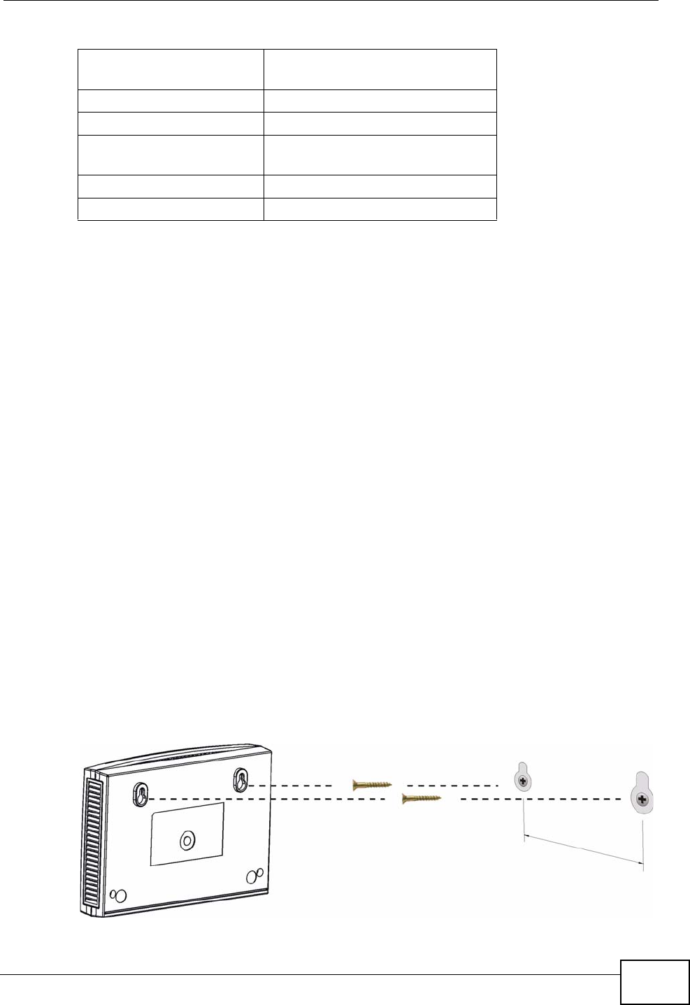
Wall-mounting Instructions
Do the following to hang your ZyXEL Device on a wall.
Note: See Table 166 on page 471 for the size of screws to use and how far apart to
place them.
1Locate a high position on a wall that is free of obstructions. Use a sturdy wall.
2Drill two holes for the screws. Make sure the distance between the centers of the
holes matches what is listed in the product specifications appendix.
Be careful to avoid damaging pipes or cables located inside the
wall when drilling holes for the screws.
3Do not screw the screws all the way into the wall. Leave a small gap of about 0.5
cm between the heads of the screws and the wall.
4Make sure the screws are snugly fastened to the wall. They need to hold the
weight of the ZyXEL Device with the connection cables.
5Align the holes on the back of the ZyXEL Device with the screws on the wall. Hang
the ZyXEL Device on the screws.
Figure 307 Wall-mounting Example
EUROPEAN PLUG
STANDARDS
AC Power Adapter Model MV18-Y180100-C5
Input Power 230V~50Hz 0.5A
UNITED KINGDOM PLUG
STANDARDS
AC Power Adapter Model MV18-Y180100-B2
Input Power 230V~50Hz 0.5A
Table 171 Power Adaptor Specifications (continued)
Chapter 30 Product Specifications
P-2612HWU-F1 User’s Guide
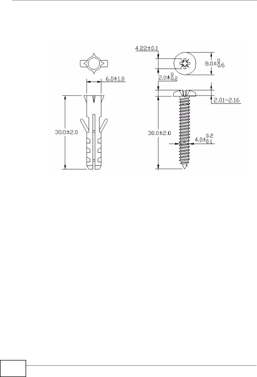
482
The following are dimensions of an M4 tap screw and masonry plug used for wall
mounting. All measurements are in millimeters (mm).
Figure 308 Masonry Plug and M4 Tap Screw

483
PART IV
Appendices and
Index
Setting Up Your Computer’s IP Address
(485)
Pop-up Windows, JavaScripts and Java
Permissions (511)
IP Addresses and Subnetting (521)
Wireless LANs (533)
Common Services (557)
Legal Information (561)
Index (565)

484

P-2612HWU-F1 User’s Guide 485
APPENDIX A
Setting Up Your Computer’s IP
Address
Note: Your specific ZyXEL Device may not support all of the operating systems
described in this appendix. See the product specifications for more information
about which operating systems are supported.
This appendix shows you how to configure the IP settings on your computer in
order for it to be able to communicate with the other devices on your network.
Windows Vista/XP/2000, Mac OS 9/OS X, and all versions of UNIX/LINUX include
the software components you need to use TCP/IP on your computer.
If you manually assign IP information instead of using a dynamic IP, make sure
that your network’s computers have IP addresses that place them in the same
subnet.
In this appendix, you can set up an IP address for:
•Windows XP/NT/2000 on page 485
•Windows Vista on page 489
•Mac OS X: 10.3 and 10.4 on page 493
•Mac OS X: 10.5 on page 497
•Linux: Ubuntu 8 (GNOME) on page 500
•Linux: openSUSE 10.3 (KDE) on page 505
Windows XP/NT/2000
The following example uses the default Windows XP display theme but can also
apply to Windows 2000 and Windows NT.
Appendix A Setting Up Your Computer’s IP Address
P-2612HWU-F1 User’s Guide
486
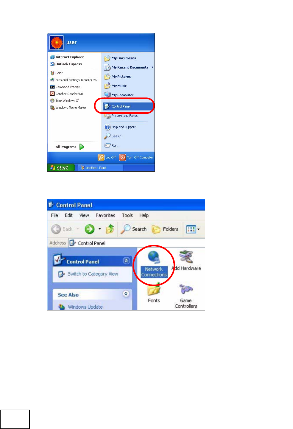
1Click Start > Control Panel.
Figure 309 Windows XP: Start Menu
2In the Control Panel, click the Network Connections icon.
Figure 310 Windows XP: Control Panel
Appendix A Setting Up Your Computer’s IP Address
P-2612HWU-F1 User’s Guide 487
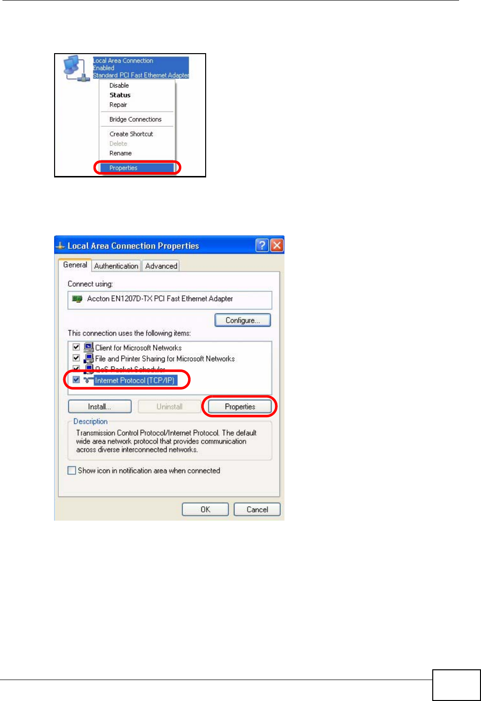
3Right-click Local Area Connection and then select Properties.
Figure 311 Windows XP: Control Panel > Network Connections > Properties
4On the General tab, select Internet Protocol (TCP/IP) and then click
Properties.
Figure 312 Windows XP: Local Area Connection Properties
Appendix A Setting Up Your Computer’s IP Address
P-2612HWU-F1 User’s Guide
488
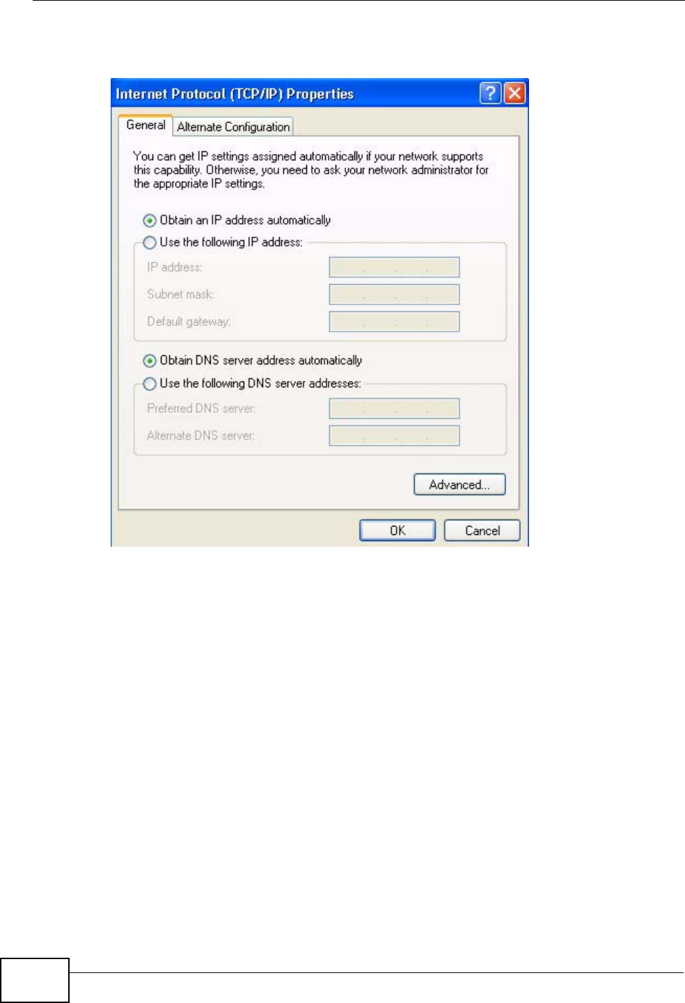
5The Internet Protocol TCP/IP Properties window opens.
Figure 313 Windows XP: Internet Protocol (TCP/IP) Properties
6Select Obtain an IP address automatically if your network administrator or ISP
assigns your IP address dynamically.
Select Use the following IP Address and fill in the IP address, Subnet mask,
and Default gateway fields if you have a static IP address that was assigned to
you by your network administrator or ISP. You may also have to enter a Preferred
DNS server and an Alternate DNS server, if that information was provided.
7Click OK to close the Internet Protocol (TCP/IP) Properties window.
8Click OK to close the Local Area Connection Properties window.
Verifying Settings
1Click Start > All Programs > Accessories > Command Prompt.
Appendix A Setting Up Your Computer’s IP Address
P-2612HWU-F1 User’s Guide 489
2In the Command Prompt window, type "ipconfig" and then press [ENTER].
You can also go to Start > Control Panel > Network Connections, right-click a
network connection, click Status and then click the Support tab to view your IP
address and connection information.
Windows Vista
This section shows screens from Windows Vista Professional.
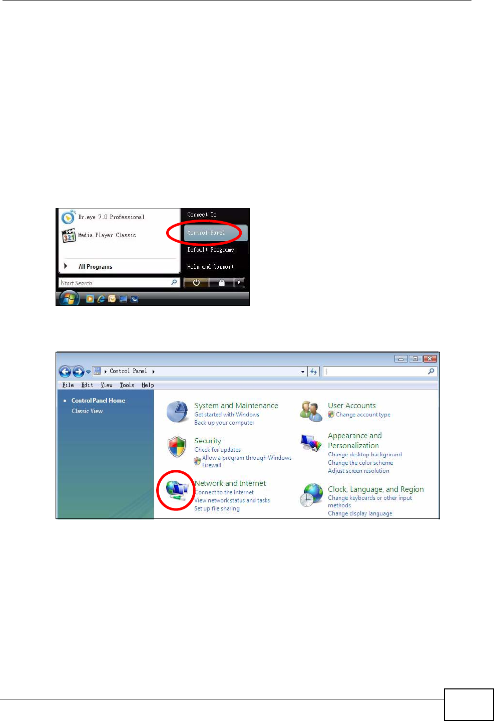
1Click Start > Control Panel.
Figure 314 Windows Vista: Start Menu
2In the Control Panel, click the Network and Internet icon.
Figure 315 Windows Vista: Control Panel
Appendix A Setting Up Your Computer’s IP Address
P-2612HWU-F1 User’s Guide
490
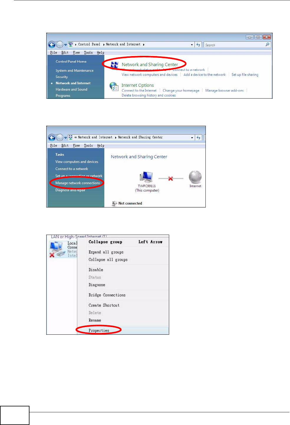
3Click the Network and Sharing Center icon.
Figure 316 Windows Vista: Network And Internet
4Click Manage network connections.
Figure 317 Windows Vista: Network and Sharing Center
5Right-click Local Area Connection and then select Properties.
Figure 318 Windows Vista: Network and Sharing Center
Note: During this procedure, click Continue whenever Windows displays a screen
saying that it needs your permission to continue.
Appendix A Setting Up Your Computer’s IP Address
P-2612HWU-F1 User’s Guide 491
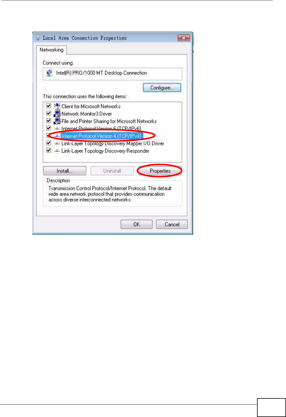
6Select Internet Protocol Version 4 (TCP/IPv4) and then select Properties.
Figure 319 Windows Vista: Local Area Connection Properties
Appendix A Setting Up Your Computer’s IP Address
P-2612HWU-F1 User’s Guide
492
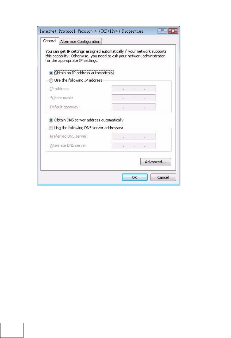
7The Internet Protocol Version 4 (TCP/IPv4) Properties window opens.
Figure 320 Windows Vista: Internet Protocol Version 4 (TCP/IPv4) Properties
8Select Obtain an IP address automatically if your network administrator or ISP
assigns your IP address dynamically.
Select Use the following IP Address and fill in the IP address, Subnet mask,
and Default gateway fields if you have a static IP address that was assigned to
you by your network administrator or ISP. You may also have to enter a Preferred
DNS server and an Alternate DNS server, if that information was
provided.Click Advanced.
9Click OK to close the Internet Protocol (TCP/IP) Properties window.
10 Click OK to close the Local Area Connection Properties window.
Verifying Settings
1Click Start > All Programs > Accessories > Command Prompt.
Appendix A Setting Up Your Computer’s IP Address
P-2612HWU-F1 User’s Guide 493
2In the Command Prompt window, type "ipconfig" and then press [ENTER].
You can also go to Start > Control Panel > Network Connections, right-click a
network connection, click Status and then click the Support tab to view your IP
address and connection information.
Mac OS X: 10.3 and 10.4
The screens in this section are from Mac OS X 10.4 but can also apply to 10.3.
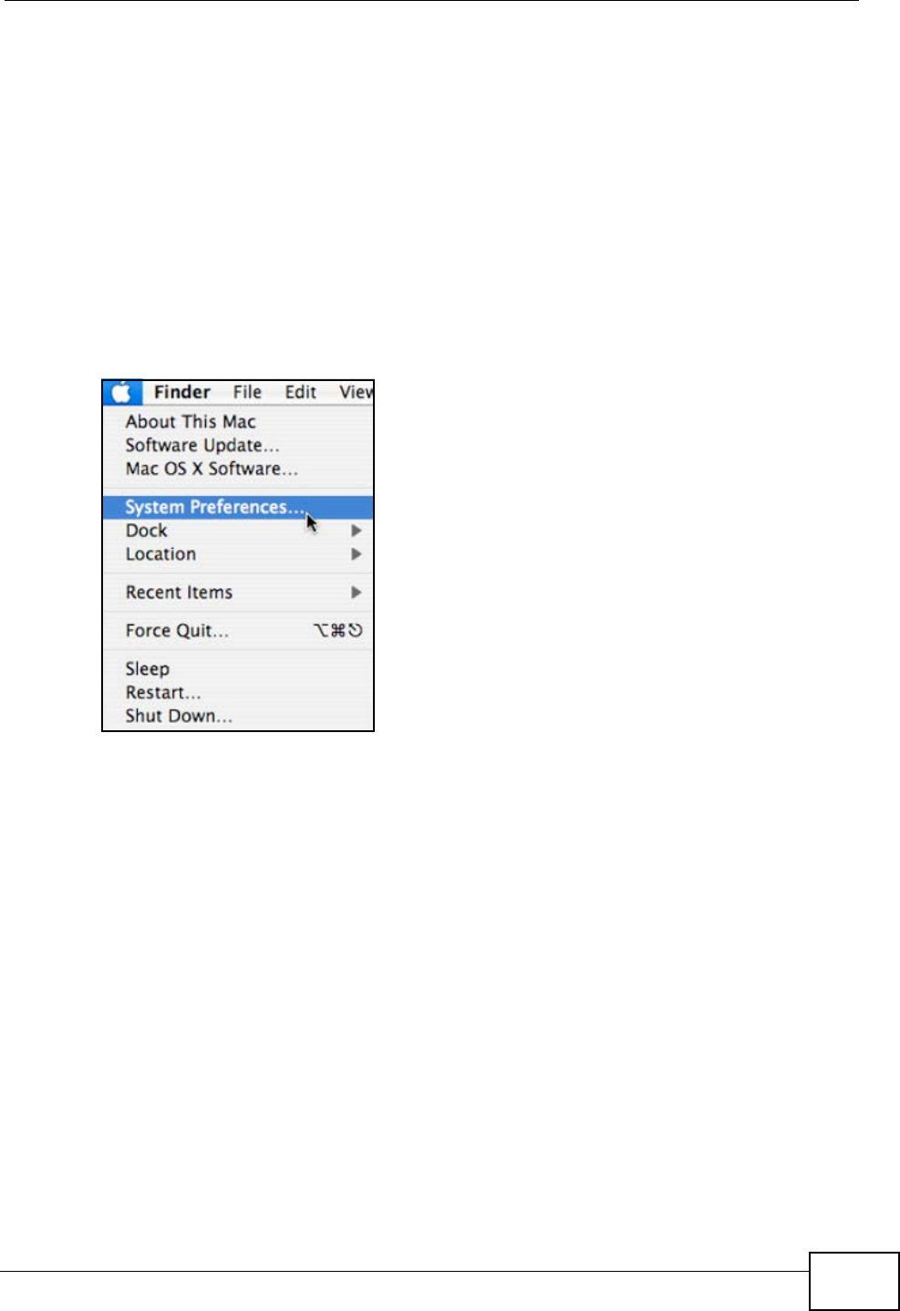
1Click Apple > System Preferences.
Figure 321 Mac OS X 10.4: Apple Menu
Appendix A Setting Up Your Computer’s IP Address
P-2612HWU-F1 User’s Guide
494
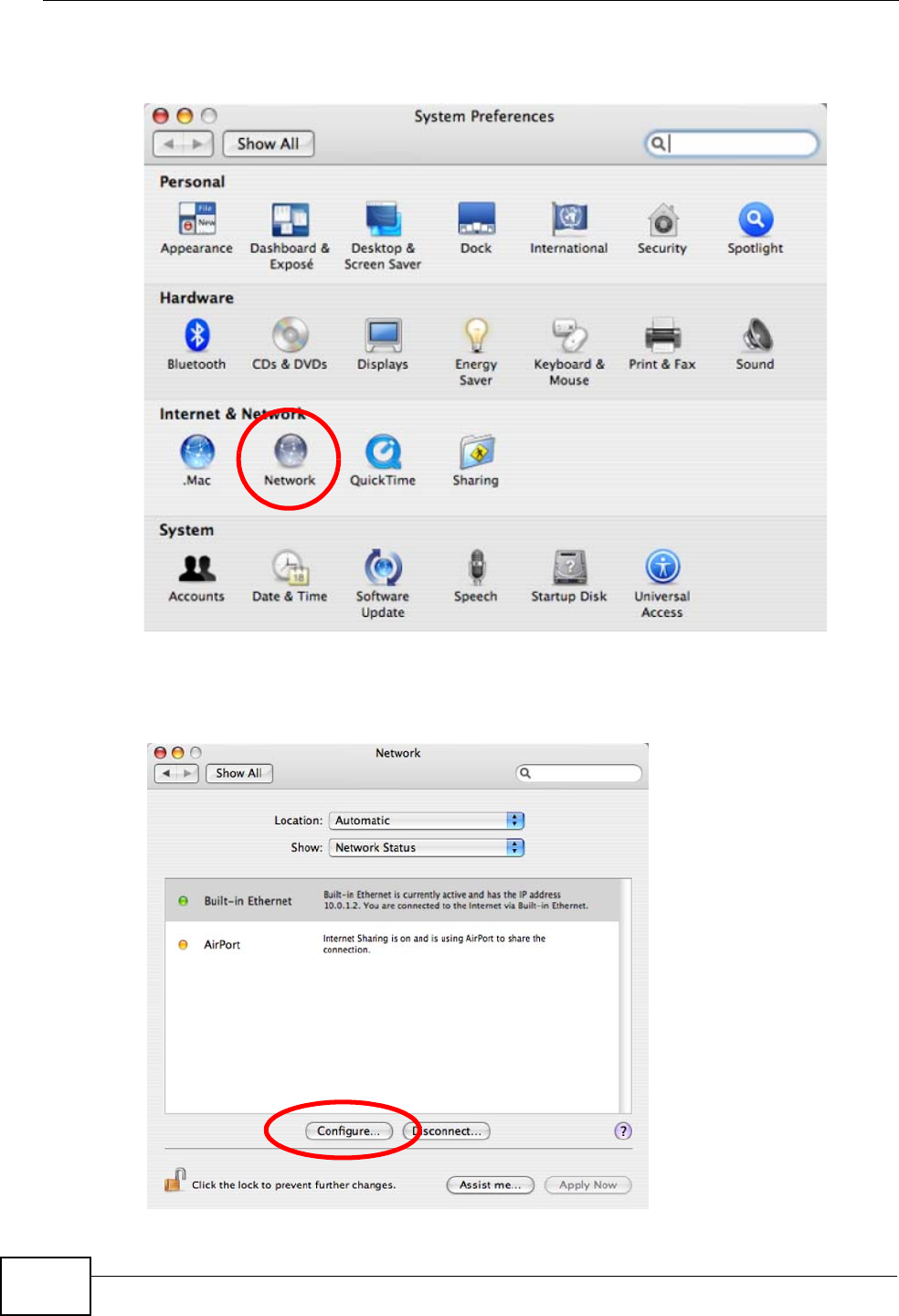
2In the System Preferences window, click the Network icon.
Figure 322 Mac OS X 10.4: System Preferences
3When the Network preferences pane opens, select Built-in Ethernet from the
network connection type list, and then click Configure.
Figure 323 Mac OS X 10.4: Network Preferences
Appendix A Setting Up Your Computer’s IP Address
P-2612HWU-F1 User’s Guide 495
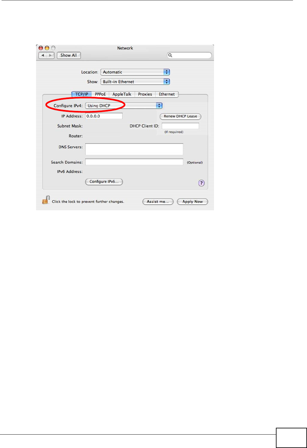
4For dynamically assigned settings, select Using DHCP from the Configure IPv4
list in the TCP/IP tab.
Figure 324 Mac OS X 10.4: Network Preferences > TCP/IP Tab.
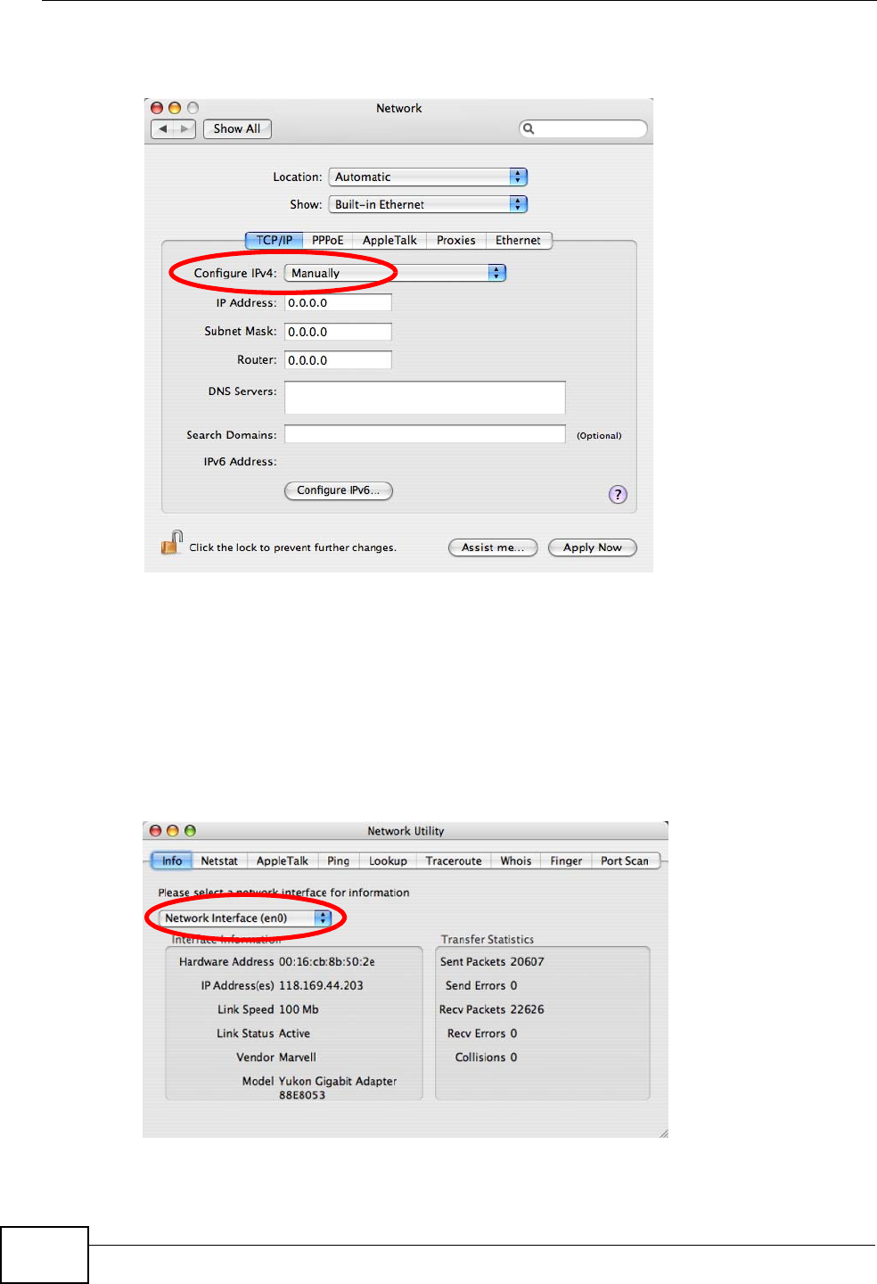
5For statically assigned settings, do the following:
•From the Configure IPv4 list, select Manually.
•In the IP Address field, type your IP address.
•In the Subnet Mask field, type your subnet mask.
Appendix A Setting Up Your Computer’s IP Address
P-2612HWU-F1 User’s Guide
496
•In the Router field, type the IP address of your device.
Figure 325 Mac OS X 10.4: Network Preferences > Ethernet
6Click Apply Now and close the window.
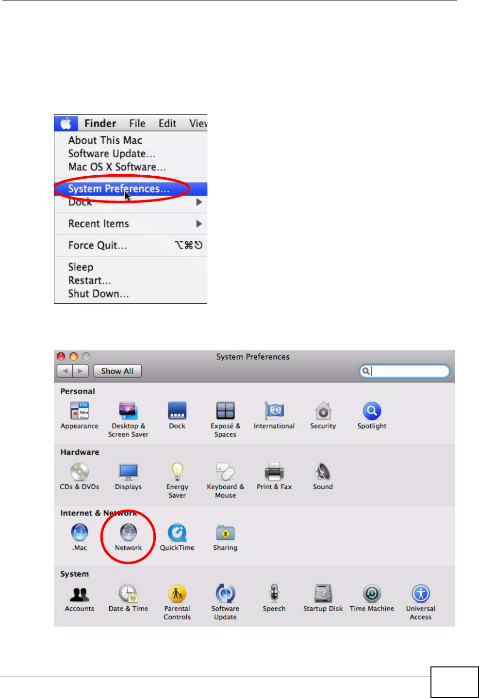
Verifying Settings
Check your TCP/IP properties by clicking Applications > Utilities > Network
Utilities, and then selecting the appropriate Network Interface from the Info
tab.
Figure 326 Mac OS X 10.4: Network Utility
Appendix A Setting Up Your Computer’s IP Address
P-2612HWU-F1 User’s Guide 497
Mac OS X: 10.5
The screens in this section are from Mac OS X 10.5.
1Click Apple > System Preferences.
Figure 327 Mac OS X 10.5: Apple Menu
2In System Preferences, click the Network icon.
Figure 328 Mac OS X 10.5: Systems Preferences
Appendix A Setting Up Your Computer’s IP Address
P-2612HWU-F1 User’s Guide
498
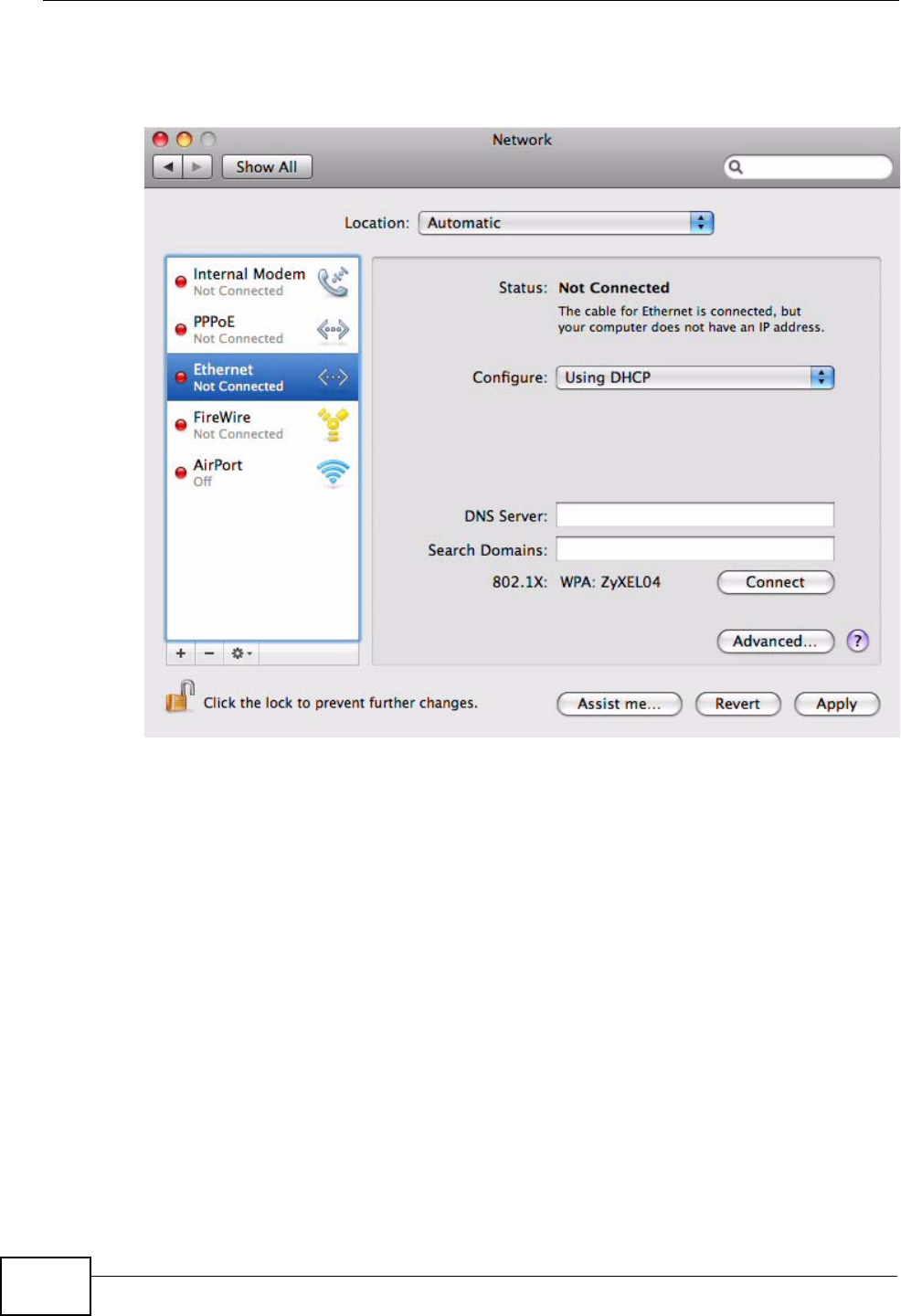
3When the Network preferences pane opens, select Ethernet from the list of
available connection types.
Figure 329 Mac OS X 10.5: Network Preferences > Ethernet
4From the Configure list, select Using DHCP for dynamically assigned settings.
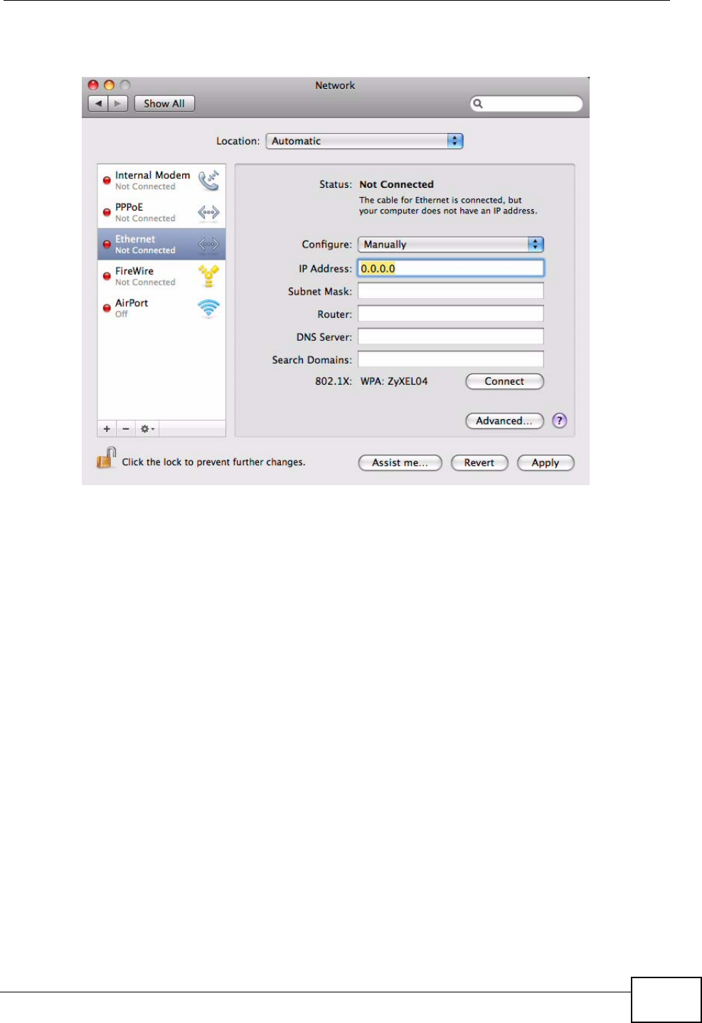
5For statically assigned settings, do the following:
•From the Configure list, select Manually.
•In the IP Address field, enter your IP address.
•In the Subnet Mask field, enter your subnet mask.
Appendix A Setting Up Your Computer’s IP Address
P-2612HWU-F1 User’s Guide 499
•In the Router field, enter the IP address of your ZyXEL Device.
Figure 330 Mac OS X 10.5: Network Preferences > Ethernet
6Click Apply and close the window.
Appendix A Setting Up Your Computer’s IP Address
P-2612HWU-F1 User’s Guide
500
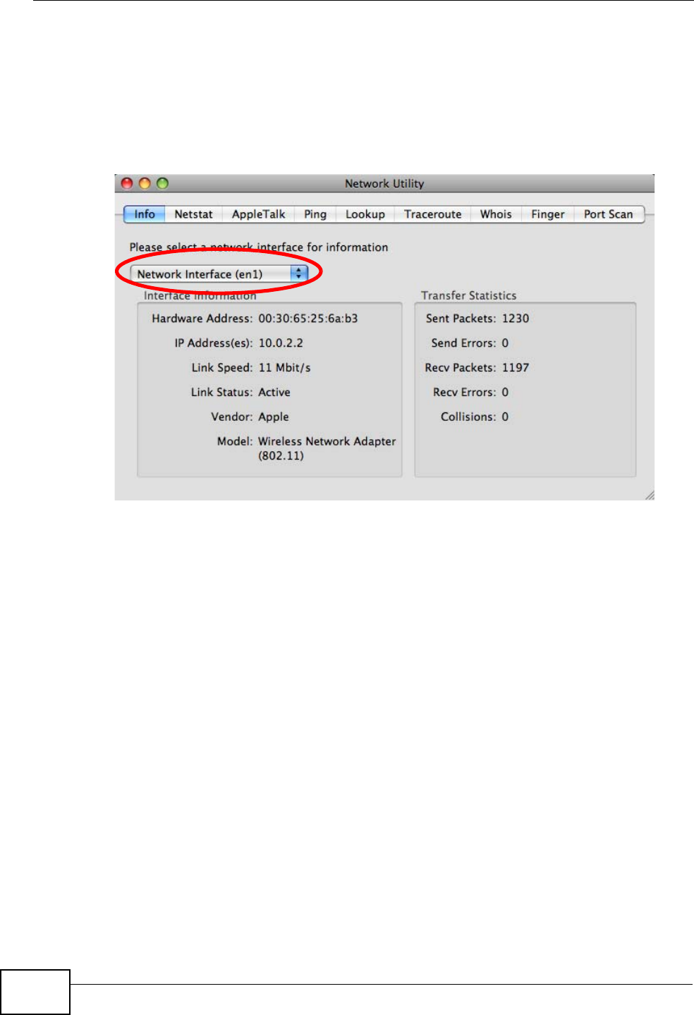
Verifying Settings
Check your TCP/IP properties by clicking Applications > Utilities > Network
Utilities, and then selecting the appropriate Network interface from the Info
tab.
Figure 331 Mac OS X 10.5: Network Utility
Linux: Ubuntu 8 (GNOME)
This section shows you how to configure your computer’s TCP/IP settings in the
GNU Object Model Environment (GNOME) using the Ubuntu 8 Linux distribution.
The procedure, screens and file locations may vary depending on your specific
distribution, release version, and individual configuration. The following screens
use the default Ubuntu 8 installation.
Note: Make sure you are logged in as the root administrator.
Follow the steps below to configure your computer IP address in GNOME:
Appendix A Setting Up Your Computer’s IP Address
P-2612HWU-F1 User’s Guide 501
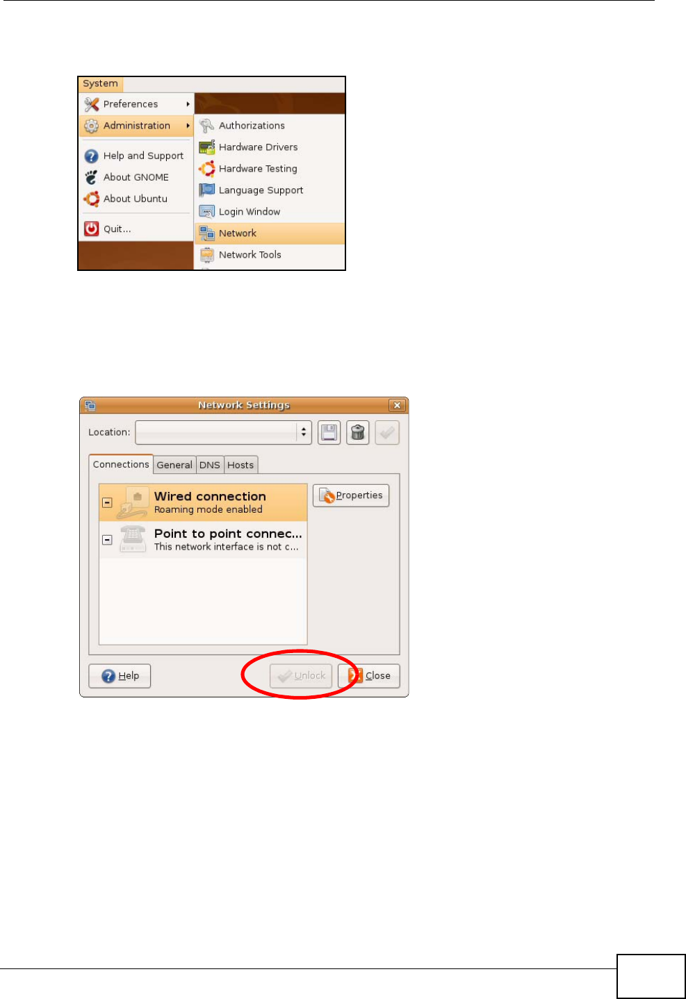
1Click System > Administration > Network.
Figure 332 Ubuntu 8: System > Administration Menu
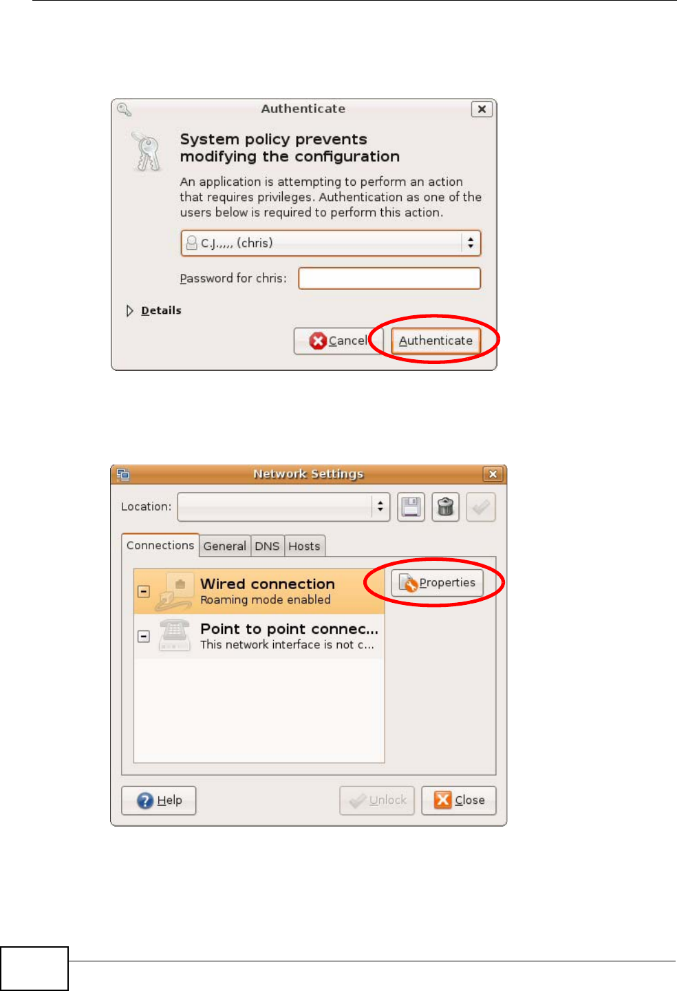
2When the Network Settings window opens, click Unlock to open the
Authenticate window. (By default, the Unlock button is greyed out until clicked.)
You cannot make changes to your configuration unless you first enter your admin
password.
Figure 333 Ubuntu 8: Network Settings > Connections
Appendix A Setting Up Your Computer’s IP Address
P-2612HWU-F1 User’s Guide
502
3In the Authenticate window, enter your admin account name and password then
click the Authenticate button.
Figure 334 Ubuntu 8: Administrator Account Authentication
4In the Network Settings window, select the connection that you want to
configure, then click Properties.
Figure 335 Ubuntu 8: Network Settings > Connections
Appendix A Setting Up Your Computer’s IP Address
P-2612HWU-F1 User’s Guide 503
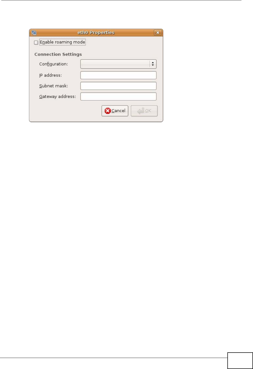
5The Properties dialog box opens.
Figure 336 Ubuntu 8: Network Settings > Properties
•In the Configuration list, select Automatic Configuration (DHCP) if you
have a dynamic IP address.
•In the Configuration list, select Static IP address if you have a static IP
address. Fill in the IP address, Subnet mask, and Gateway address fields.
6Click OK to save the changes and close the Properties dialog box and return to
the Network Settings screen.
Appendix A Setting Up Your Computer’s IP Address
P-2612HWU-F1 User’s Guide
504
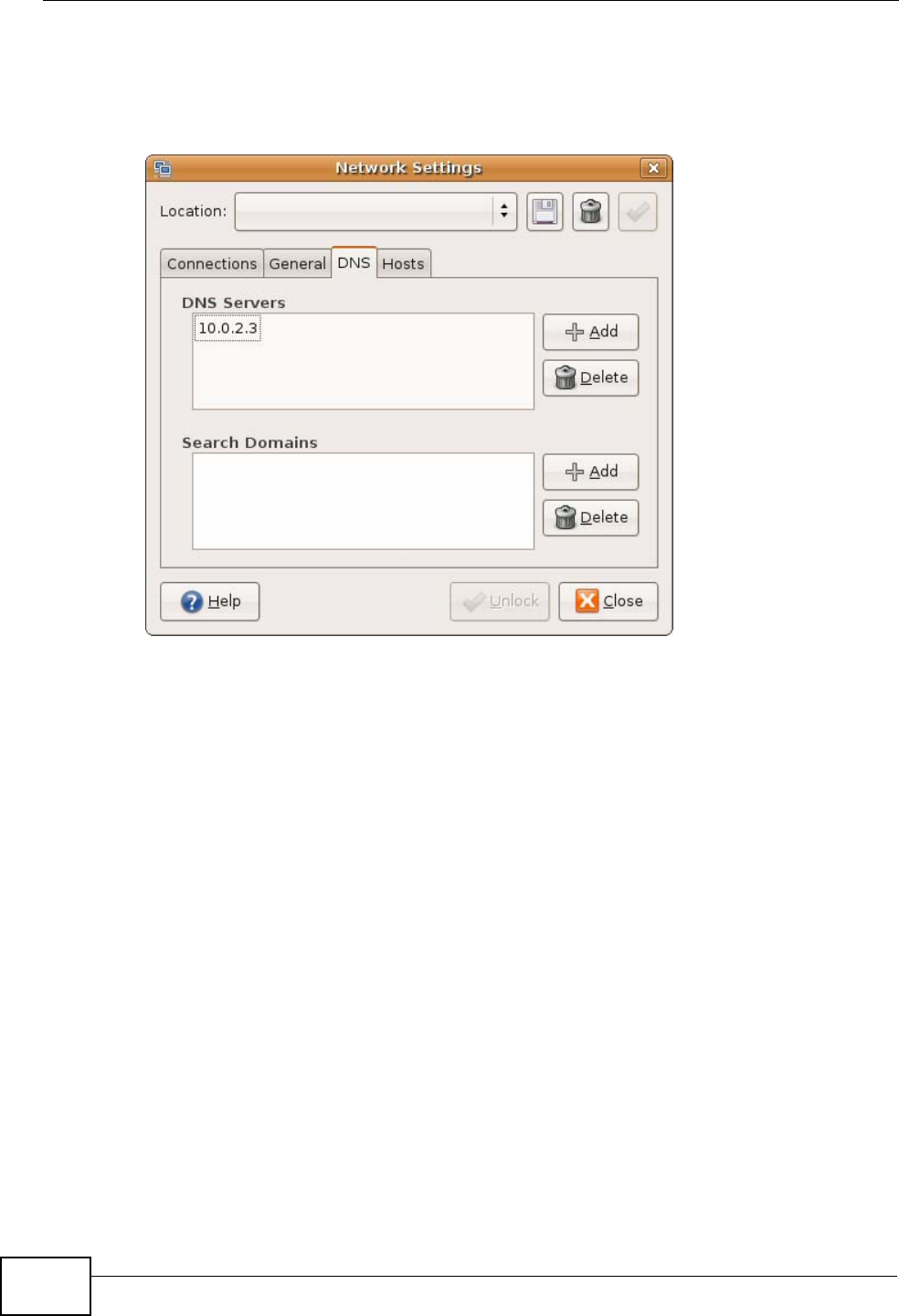
7If you know your DNS server IP address(es), click the DNS tab in the Network
Settings window and then enter the DNS server information in the fields
provided.
Figure 337 Ubuntu 8: Network Settings > DNS
8Click the Close button to apply the changes.
Verifying Settings
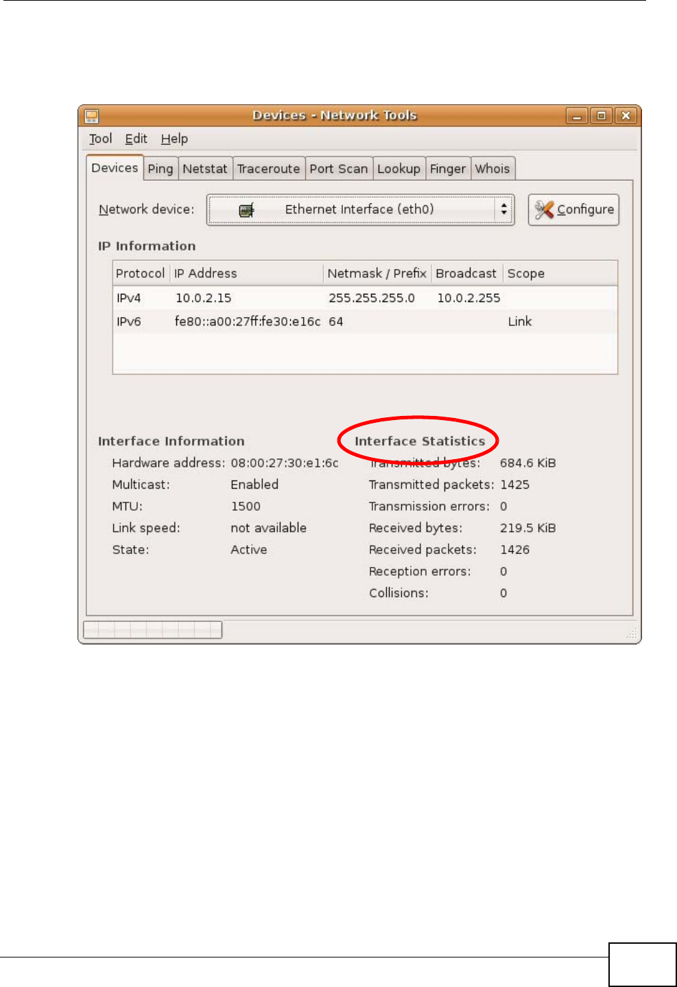
Check your TCP/IP properties by clicking System > Administration > Network
Tools, and then selecting the appropriate Network device from the Devices
Appendix A Setting Up Your Computer’s IP Address
P-2612HWU-F1 User’s Guide 505
tab. The Interface Statistics column shows data if your connection is working
properly.
Figure 338 Ubuntu 8: Network Tools
Linux: openSUSE 10.3 (KDE)
This section shows you how to configure your computer’s TCP/IP settings in the K
Desktop Environment (KDE) using the openSUSE 10.3 Linux distribution. The
procedure, screens and file locations may vary depending on your specific
distribution, release version, and individual configuration. The following screens
use the default openSUSE 10.3 installation.
Note: Make sure you are logged in as the root administrator.
Follow the steps below to configure your computer IP address in the KDE:
Appendix A Setting Up Your Computer’s IP Address
P-2612HWU-F1 User’s Guide
506
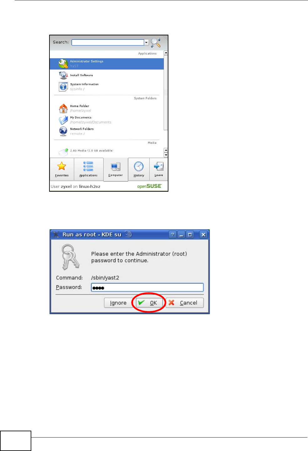
1Click K Menu > Computer > Administrator Settings (YaST).
Figure 339 openSUSE 10.3: K Menu > Computer Menu
2When the Run as Root - KDE su dialog opens, enter the admin password and
click OK.
Figure 340 openSUSE 10.3: K Menu > Computer Menu
Appendix A Setting Up Your Computer’s IP Address
P-2612HWU-F1 User’s Guide 507
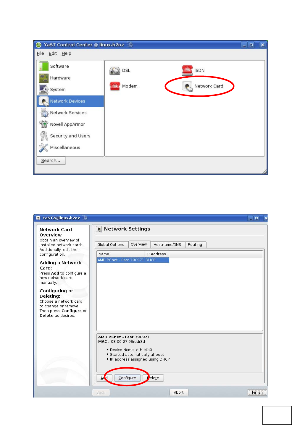
3When the YaST Control Center window opens, select Network Devices and
then click the Network Card icon.
Figure 341 openSUSE 10.3: YaST Control Center
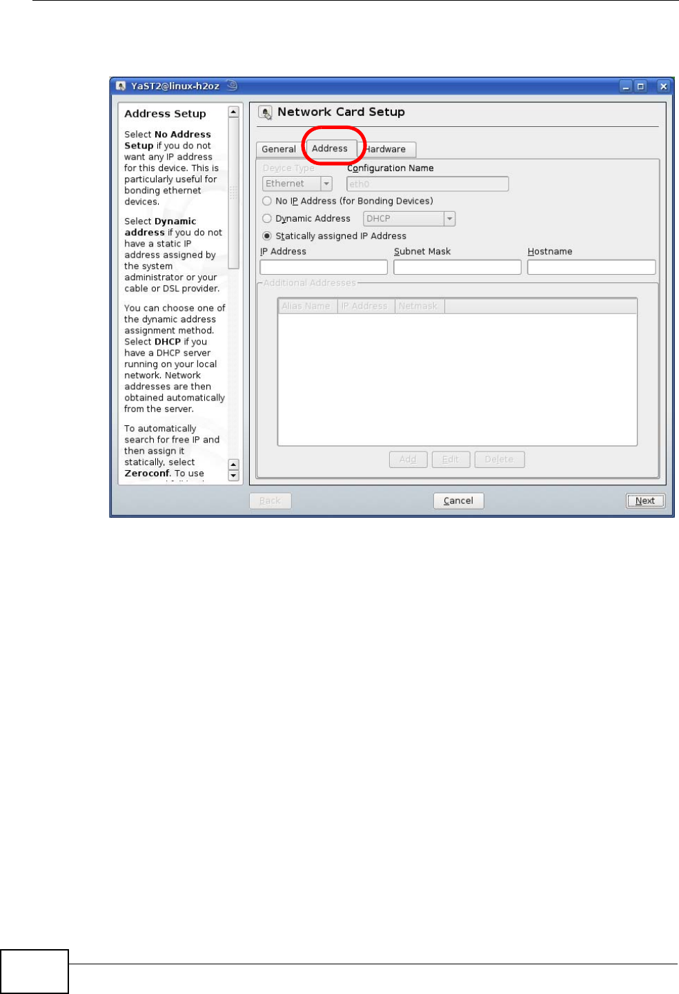
4When the Network Settings window opens, click the Overview tab, select the
appropriate connection Name from the list, and then click the Configure button.
Figure 342 openSUSE 10.3: Network Settings
Appendix A Setting Up Your Computer’s IP Address
P-2612HWU-F1 User’s Guide
508
5When the Network Card Setup window opens, click the Address tab
Figure 343 openSUSE 10.3: Network Card Setup
6Select Dynamic Address (DHCP) if you have a dynamic IP address.
Select Statically assigned IP Address if you have a static IP address. Fill in the
IP address, Subnet mask, and Hostname fields.
7Click Next to save the changes and close the Network Card Setup window.
Appendix A Setting Up Your Computer’s IP Address
P-2612HWU-F1 User’s Guide 509
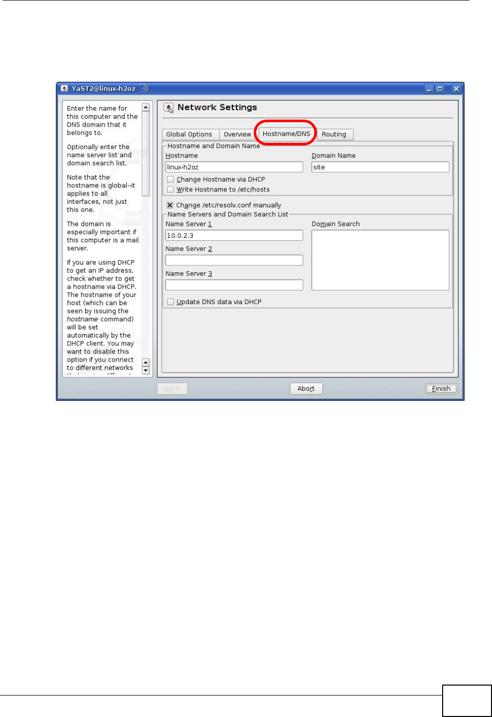
8If you know your DNS server IP address(es), click the Hostname/DNS tab in
Network Settings and then enter the DNS server information in the fields
provided.
Figure 344 openSUSE 10.3: Network Settings
9Click Finish to save your settings and close the window.
Appendix A Setting Up Your Computer’s IP Address
P-2612HWU-F1 User’s Guide
510
Verifying Settings
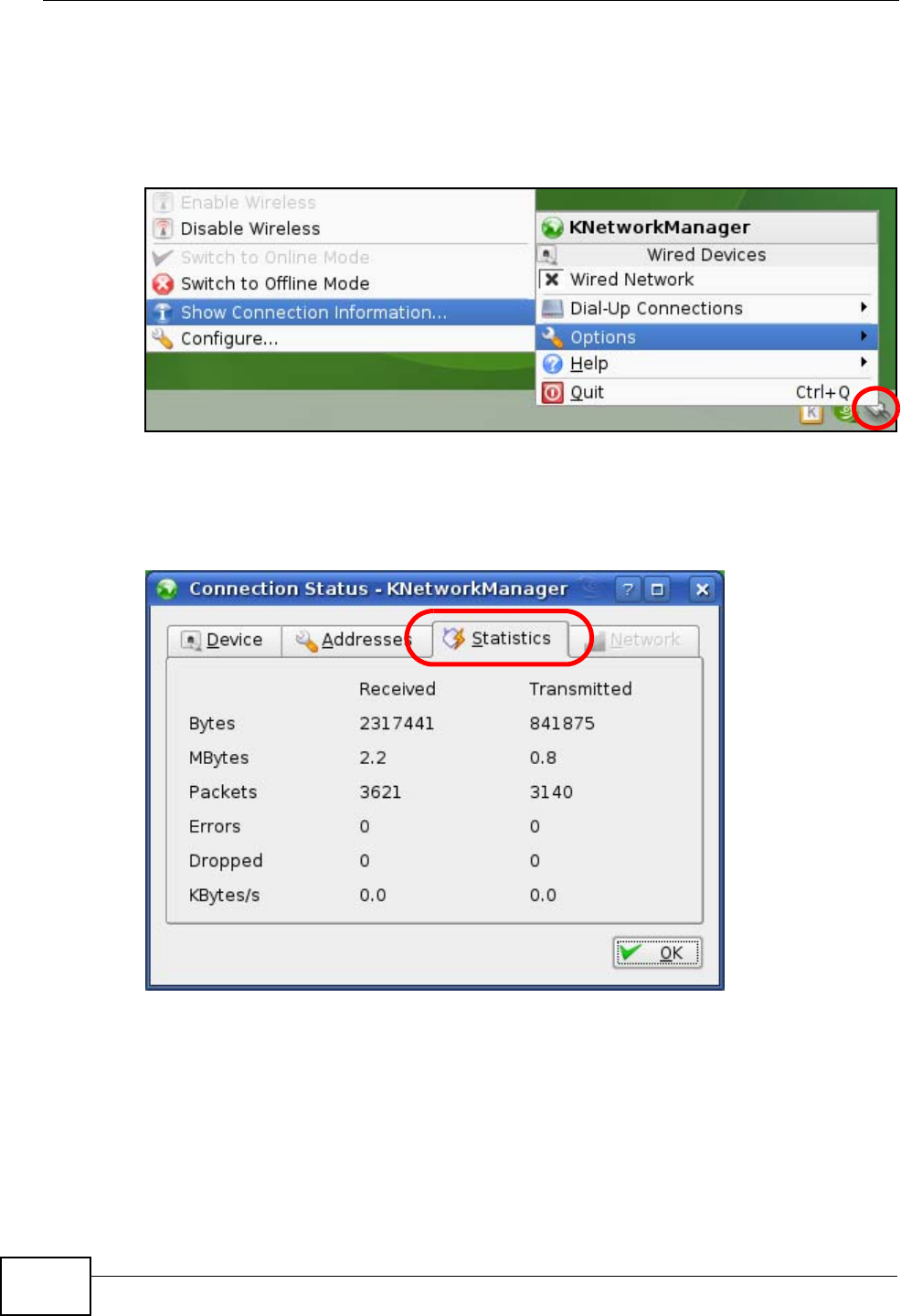
Click the KNetwork Manager icon on the Task bar to check your TCP/IP
properties. From the Options sub-menu, select Show Connection Information.
Figure 345 openSUSE 10.3: KNetwork Manager
When the Connection Status - KNetwork Manager window opens, click the
Statistics tab to see if your connection is working properly.
Figure 346 openSUSE: Connection Status - KNetwork Manager

P-2612HWU-F1 User’s Guide 511
APPENDIX B
Pop-up Windows, JavaScripts
and Java Permissions
In order to use the web configurator you need to allow:
• Web browser pop-up windows from your device.
• JavaScripts (enabled by default).
• Java permissions (enabled by default).
Note: Internet Explorer 6 screens are used here. Screens for other Internet Explorer
versions may vary.
Internet Explorer Pop-up Blockers
You may have to disable pop-up blocking to log into your device.
Either disable pop-up blocking (enabled by default in Windows XP SP (Service
Pack) 2) or allow pop-up blocking and create an exception for your device’s IP
address.
Disable Pop-up Blockers
1In Internet Explorer, select Tools, Pop-up Blocker and then select Turn Off
Pop-up Blocker.
Figure 347 Pop-up Blocker
You can also check if pop-up blocking is disabled in the Pop-up Blocker section in
the Privacy tab.
Appendix B Pop-up Windows, JavaScripts and Java Permissions
P-2612HWU-F1 User’s Guide
512
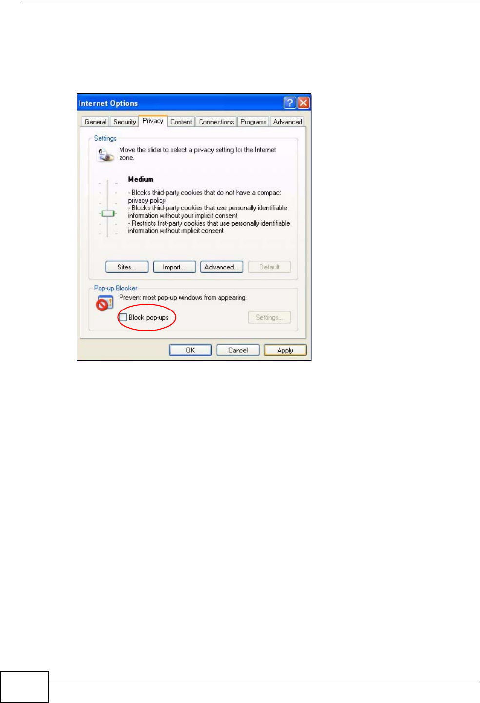
1In Internet Explorer, select Tools, Internet Options, Privacy.
2Clear the Block pop-ups check box in the Pop-up Blocker section of the screen.
This disables any web pop-up blockers you may have enabled.
Figure 348 Internet Options: Privacy
3Click Apply to save this setting.
Enable Pop-up Blockers with Exceptions
Alternatively, if you only want to allow pop-up windows from your device, see the
following steps.
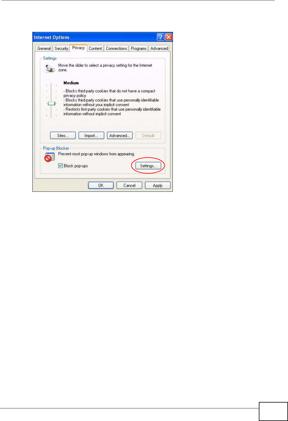
1In Internet Explorer, select Tools, Internet Options and then the Privacy tab.
Appendix B Pop-up Windows, JavaScripts and Java Permissions
P-2612HWU-F1 User’s Guide 513
2Select Settings…to open the Pop-up Blocker Settings screen.
Figure 349 Internet Options: Privacy
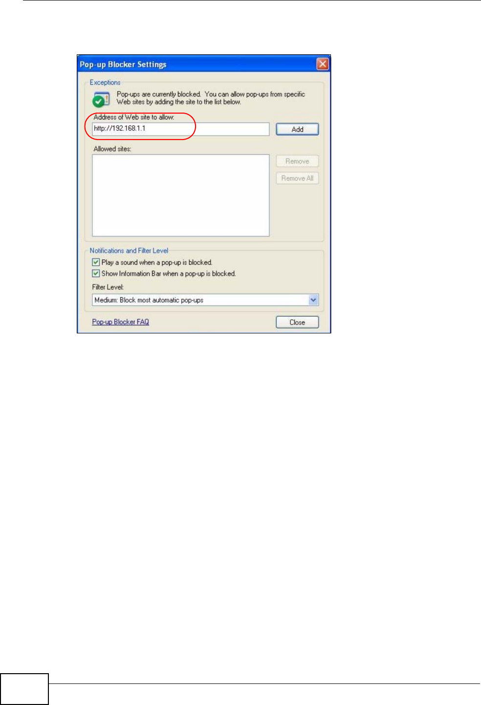
3Type the IP address of your device (the web page that you do not want to have
blocked) with the prefix “http://”. For example, http://192.168.167.1.
Appendix B Pop-up Windows, JavaScripts and Java Permissions
P-2612HWU-F1 User’s Guide
514
4Click Add to move the IP address to the list of Allowed sites.
Figure 350 Pop-up Blocker Settings
5Click Close to return to the Privacy screen.
6Click Apply to save this setting.
JavaScripts
If pages of the web configurator do not display properly in Internet Explorer, check
that JavaScripts are allowed.
Appendix B Pop-up Windows, JavaScripts and Java Permissions
P-2612HWU-F1 User’s Guide 515
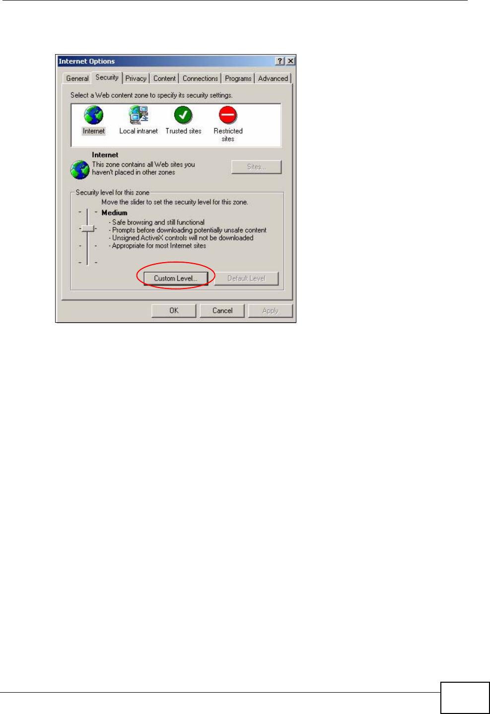
1In Internet Explorer, click Tools, Internet Options and then the Security tab.
Figure 351 Internet Options: Security
2Click the Custom Level... button.
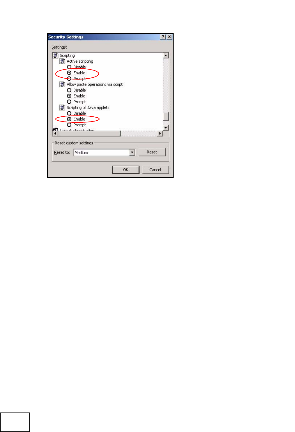
3Scroll down to Scripting.
4Under Active scripting make sure that Enable is selected (the default).
5Under Scripting of Java applets make sure that Enable is selected (the
default).
Appendix B Pop-up Windows, JavaScripts and Java Permissions
P-2612HWU-F1 User’s Guide
516
6Click OK to close the window.
Figure 352 Security Settings - Java Scripting
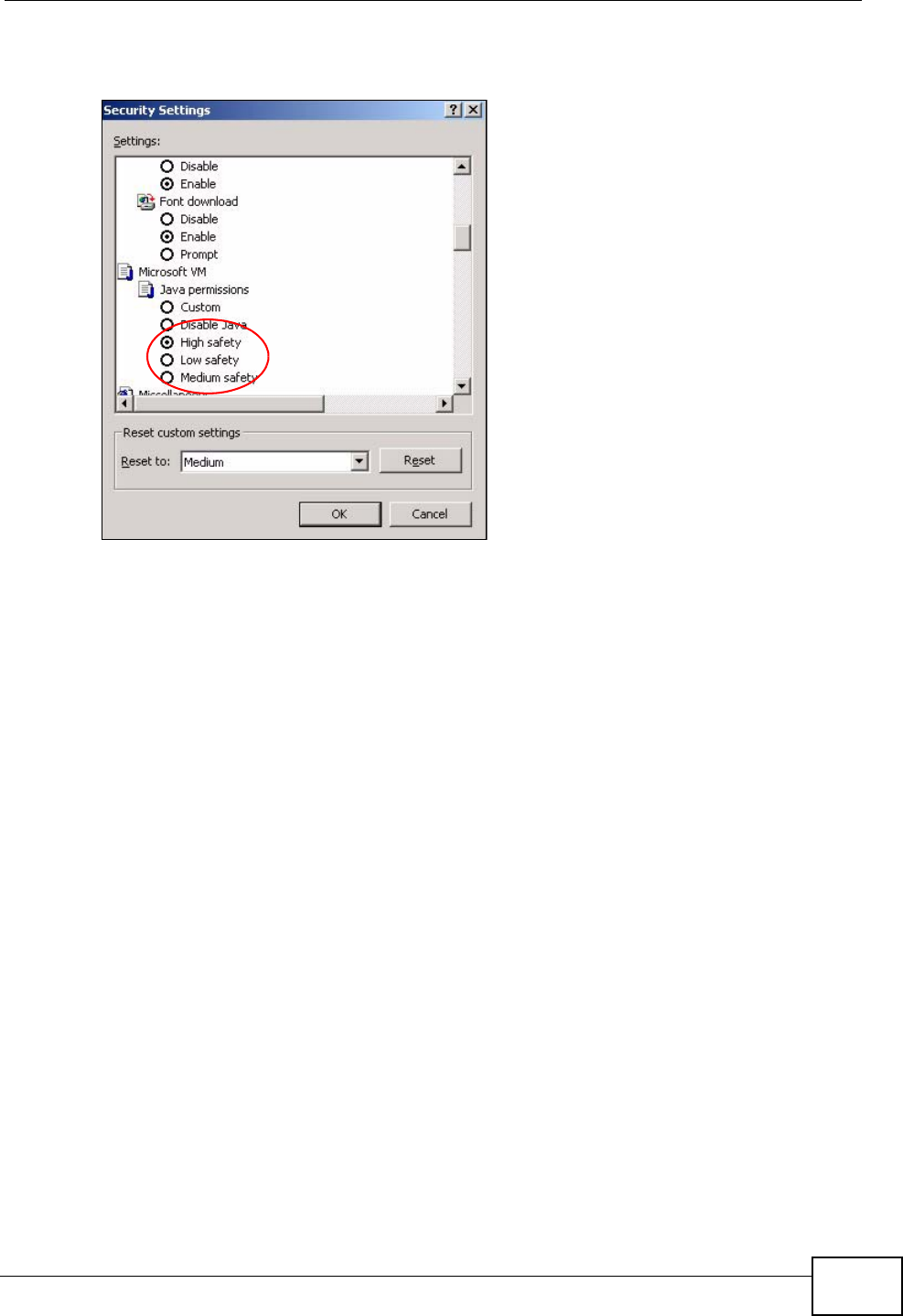
Java Permissions
1From Internet Explorer, click Tools, Internet Options and then the Security
tab.
2Click the Custom Level... button.
3Scroll down to Microsoft VM.
4Under Java permissions make sure that a safety level is selected.
Appendix B Pop-up Windows, JavaScripts and Java Permissions
P-2612HWU-F1 User’s Guide 517
5Click OK to close the window.
Figure 353 Security Settings - Java
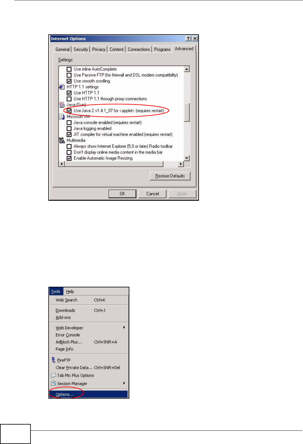
JAVA (Sun)
1From Internet Explorer, click Tools, Internet Options and then the Advanced
tab.
2Make sure that Use Java 2 for <applet> under Java (Sun) is selected.
Appendix B Pop-up Windows, JavaScripts and Java Permissions
P-2612HWU-F1 User’s Guide
518
3Click OK to close the window.
Figure 354 Java (Sun)
Mozilla Firefox
Mozilla Firefox 2.0 screens are used here. Screens for other versions may vary.
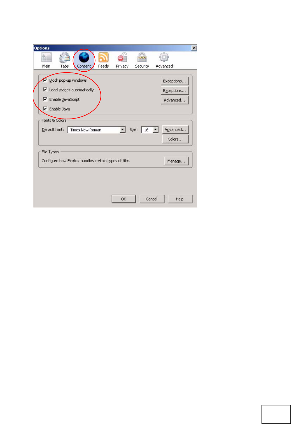
You can enable Java, Javascripts and pop-ups in one screen. Click Tools, then
click Options in the screen that appears.
Figure 355 Mozilla Firefox: Tools > Options
Appendix B Pop-up Windows, JavaScripts and Java Permissions
P-2612HWU-F1 User’s Guide 519
Click Content.to show the screen below. Select the check boxes as shown in the
following screen.
Figure 356 Mozilla Firefox Content Security

Appendix B Pop-up Windows, JavaScripts and Java Permissions
P-2612HWU-F1 User’s Guide
520

P-2612HWU-F1 User’s Guide 521
APPENDIX C
IP Addresses and Subnetting
This appendix introduces IP addresses and subnet masks.
IP addresses identify individual devices on a network. Every networking device
(such as computers, servers, routers, and printers) needs an IP address to
communicate across the network. These networking devices are also known as
hosts.
Subnet masks determine the maximum number of possible hosts on a network.
You can also use subnet masks to divide one network into multiple sub-networks.
Introduction to IP Addresses
One part of the IP address is the network number, and the other part is the host
ID. In the same way that houses on a street share a common street name, the
hosts on a network share a common network number. Similarly, as each house
has its own house number, each host on the network has its own unique
identifying number - the host ID. Routers use the network number to send packets
to the correct network, while the host ID determines to which host on the network
the packets are delivered.
Structure
An IP address is made up of four parts, written in dotted decimal notation (for
example, 192.168.1.1). Each of these four parts is known as an octet. An octet is
an eight-digit binary number (for example 11000000, which is 192 in decimal
notation).
Therefore, each octet has a possible range of 00000000 to 11111111 in binary, or
0 to 255 in decimal.
Appendix C IP Addresses and Subnetting
P-2612HWU-F1 User’s Guide
522
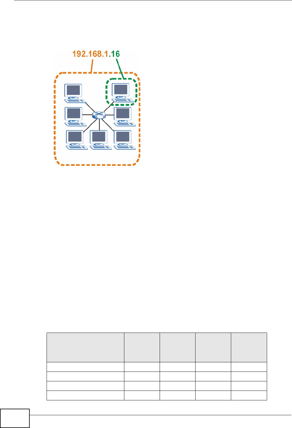
The following figure shows an example IP address in which the first three octets
(192.168.1) are the network number, and the fourth octet (16) is the host ID.
Figure 357 Network Number and Host ID
How much of the IP address is the network number and how much is the host ID
varies according to the subnet mask.
Subnet Masks
A subnet mask is used to determine which bits are part of the network number,
and which bits are part of the host ID (using a logical AND operation). The term
“subnet” is short for “sub-network”.
A subnet mask has 32 bits. If a bit in the subnet mask is a “1” then the
corresponding bit in the IP address is part of the network number. If a bit in the
subnet mask is “0” then the corresponding bit in the IP address is part of the host
ID.
The following example shows a subnet mask identifying the network number (in
bold text) and host ID of an IP address (192.168.1.2 in decimal).
Table 172 IP Address Network Number and Host ID Example
1ST
OCTET:
(192)
2ND
OCTET:
(168)
3RD
OCTET:
(1)
4TH
OCTET
(2)
IP Address (Binary) 11000000 10101000 00000001 00000010
Subnet Mask (Binary) 11111111 11111111 11111111 00000000
Network Number 11000000 10101000 00000001
Host ID 00000010

Appendix C IP Addresses and Subnetting
P-2612HWU-F1 User’s Guide 523
By convention, subnet masks always consist of a continuous sequence of ones
beginning from the leftmost bit of the mask, followed by a continuous sequence of
zeros, for a total number of 32 bits.
Subnet masks can be referred to by the size of the network number part (the bits
with a “1” value). For example, an “8-bit mask” means that the first 8 bits of the
mask are ones and the remaining 24 bits are zeroes.
Subnet masks are expressed in dotted decimal notation just like IP addresses. The
following examples show the binary and decimal notation for 8-bit, 16-bit, 24-bit
and 29-bit subnet masks.
Network Size
The size of the network number determines the maximum number of possible
hosts you can have on your network. The larger the number of network number
bits, the smaller the number of remaining host ID bits.
An IP address with host IDs of all zeros is the IP address of the network
(192.168.1.0 with a 24-bit subnet mask, for example). An IP address with host
IDs of all ones is the broadcast address for that network (192.168.1.255 with a
24-bit subnet mask, for example).
As these two IP addresses cannot be used for individual hosts, calculate the
maximum number of possible hosts in a network as follows:
Table 173 Subnet Masks
BINARY
DECIMAL
1ST
OCTET 2ND
OCTET 3RD
OCTET 4TH
OCTET
8-bit mask 11111111 00000000 00000000 00000000 255.0.0.0
16-bit mask 11111111 11111111 00000000 00000000 255.255.0.0
24-bit mask 11111111 11111111 11111111 00000000 255.255.255.0
29-bit mask 11111111 11111111 11111111 11111000 255.255.255.248
Table 174 Maximum Host Numbers
SUBNET MASK HOST ID SIZE MAXIMUM NUMBER OF
HOSTS
8 bits 255.0.0.0 24 bits 224 – 2 16777214
16 bits 255.255.0.0 16 bits 216 – 2 65534
24 bits 255.255.255.0 8 bits 28 – 2 254
29 bits 255.255.255.248 3 bits 23 – 2 6

Appendix C IP Addresses and Subnetting
P-2612HWU-F1 User’s Guide
524
Notation
Since the mask is always a continuous number of ones beginning from the left,
followed by a continuous number of zeros for the remainder of the 32 bit mask,
you can simply specify the number of ones instead of writing the value of each
octet. This is usually specified by writing a “/” followed by the number of bits in
the mask after the address.
For example, 192.1.1.0 /25 is equivalent to saying 192.1.1.0 with subnet mask
255.255.255.128.
The following table shows some possible subnet masks using both notations.
Subnetting
You can use subnetting to divide one network into multiple sub-networks. In the
following example a network administrator creates two sub-networks to isolate a
group of servers from the rest of the company network for security reasons.
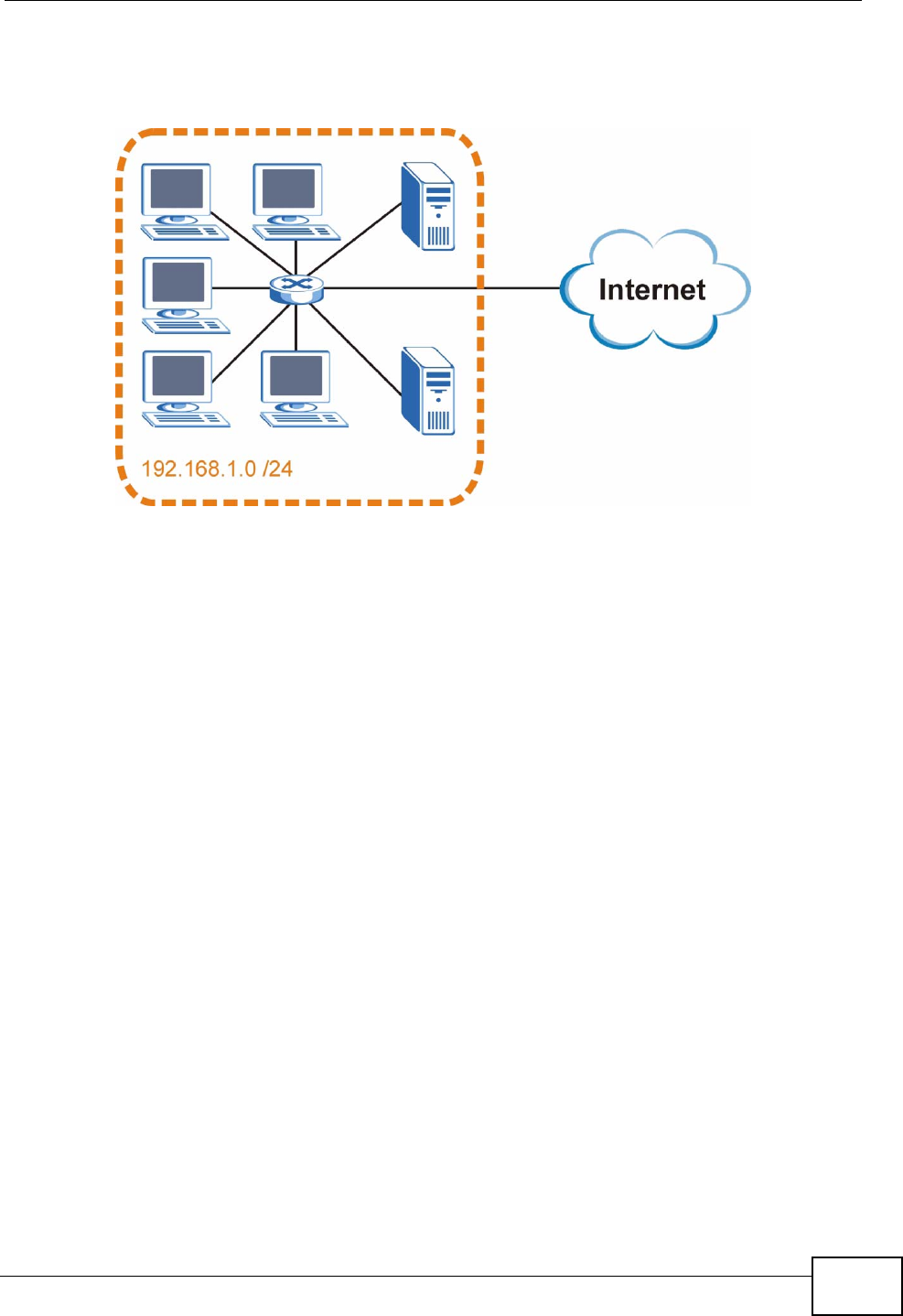
In this example, the company network address is 192.168.1.0. The first three
octets of the address (192.168.1) are the network number, and the remaining
octet is the host ID, allowing a maximum of 28 – 2 or 254 possible hosts.
Table 175 Alternative Subnet Mask Notation
SUBNET MASK ALTERNATIVE
NOTATION LAST OCTET
(BINARY) LAST OCTET
(DECIMAL)
255.255.255.0 /24 0000 0000 0
255.255.255.128 /25 1000 0000 128
255.255.255.192 /26 1100 0000 192
255.255.255.224 /27 1110 0000 224
255.255.255.240 /28 1111 0000 240
255.255.255.248 /29 1111 1000 248
255.255.255.252 /30 1111 1100 252
Appendix C IP Addresses and Subnetting
P-2612HWU-F1 User’s Guide 525
The following figure shows the company network before subnetting.
Figure 358 Subnetting Example: Before Subnetting
You can “borrow” one of the host ID bits to divide the network 192.168.1.0 into
two separate sub-networks. The subnet mask is now 25 bits (255.255.255.128 or
/25).
The “borrowed” host ID bit can have a value of either 0 or 1, allowing two
subnets; 192.168.1.0 /25 and 192.168.1.128 /25.
Appendix C IP Addresses and Subnetting
P-2612HWU-F1 User’s Guide
526
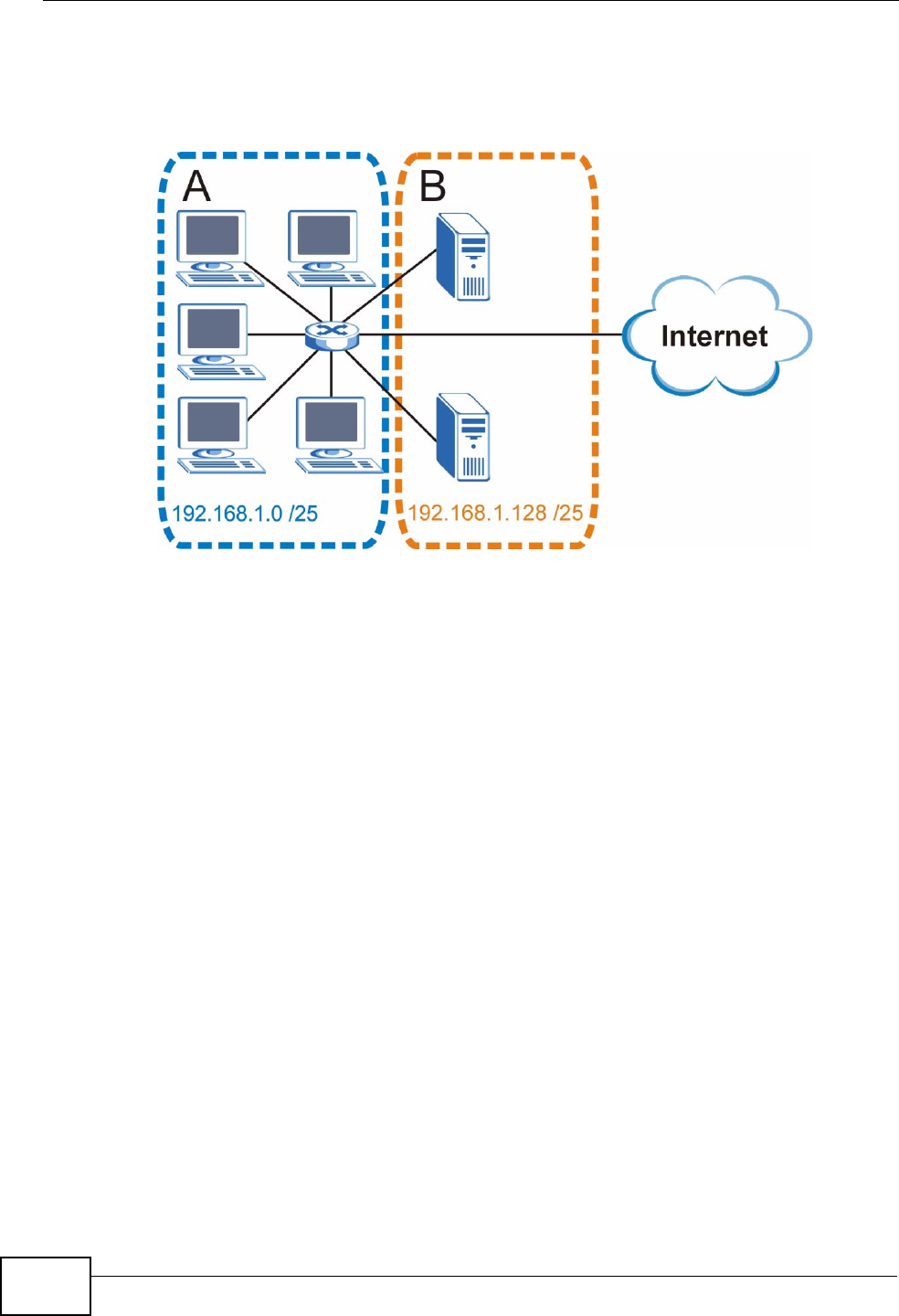
The following figure shows the company network after subnetting. There are now
two sub-networks, A and B.
Figure 359 Subnetting Example: After Subnetting
In a 25-bit subnet the host ID has 7 bits, so each sub-network has a maximum of
27 – 2 or 126 possible hosts (a host ID of all zeroes is the subnet’s address itself,
all ones is the subnet’s broadcast address).
192.168.1.0 with mask 255.255.255.128 is subnet A itself, and 192.168.1.127
with mask 255.255.255.128 is its broadcast address. Therefore, the lowest IP
address that can be assigned to an actual host for subnet A is 192.168.1.1 and
the highest is 192.168.1.126.
Similarly, the host ID range for subnet B is 192.168.1.129 to 192.168.1.254.
Example: Four Subnets
The previous example illustrated using a 25-bit subnet mask to divide a 24-bit
address into two subnets. Similarly, to divide a 24-bit address into four subnets,
you need to “borrow” two host ID bits to give four possible combinations (00, 01,
10 and 11). The subnet mask is 26 bits
(11111111.11111111.11111111.11000000) or 255.255.255.192.

Appendix C IP Addresses and Subnetting
P-2612HWU-F1 User’s Guide 527
Each subnet contains 6 host ID bits, giving 26 - 2 or 62 hosts for each subnet (a
host ID of all zeroes is the subnet itself, all ones is the subnet’s broadcast
address).
Table 176 Subnet 1
IP/SUBNET MASK NETWORK NUMBER LAST OCTET BIT
VALUE
IP Address (Decimal) 192.168.1. 0
IP Address (Binary) 11000000.10101000.00000001. 00000000
Subnet Mask (Binary) 11111111.11111111.11111111. 11000000
Subnet Address:
192.168.1.0 Lowest Host ID: 192.168.1.1
Broadcast Address:
192.168.1.63 Highest Host ID: 192.168.1.62
Table 177 Subnet 2
IP/SUBNET MASK NETWORK NUMBER LAST OCTET BIT
VALUE
IP Address 192.168.1. 64
IP Address (Binary) 11000000.10101000.00000001. 01000000
Subnet Mask (Binary) 11111111.11111111.11111111. 11000000
Subnet Address:
192.168.1.64 Lowest Host ID: 192.168.1.65
Broadcast Address:
192.168.1.127 Highest Host ID: 192.168.1.126
Table 178 Subnet 3
IP/SUBNET MASK NETWORK NUMBER LAST OCTET BIT
VALUE
IP Address 192.168.1. 128
IP Address (Binary) 11000000.10101000.00000001. 10000000
Subnet Mask (Binary) 11111111.11111111.11111111. 11000000
Subnet Address:
192.168.1.128 Lowest Host ID: 192.168.1.129
Broadcast Address:
192.168.1.191 Highest Host ID: 192.168.1.190
Table 179 Subnet 4
IP/SUBNET MASK NETWORK NUMBER LAST OCTET BIT
VALUE
IP Address 192.168.1. 192
IP Address (Binary) 11000000.10101000.00000001. 11000000
Subnet Mask (Binary) 11111111.11111111.11111111. 11000000
Subnet Address:
192.168.1.192 Lowest Host ID: 192.168.1.193
Broadcast Address:
192.168.1.255 Highest Host ID: 192.168.1.254
Appendix C IP Addresses and Subnetting
P-2612HWU-F1 User’s Guide
528
Example: Eight Subnets
Similarly, use a 27-bit mask to create eight subnets (000, 001, 010, 011, 100,
101, 110 and 111).
The following table shows IP address last octet values for each subnet.
Subnet Planning
The following table is a summary for subnet planning on a network with a 24-bit
network number.
The following table is a summary for subnet planning on a network with a 16-bit
network number.
Table 180 Eight Subnets
SUBNET SUBNET
ADDRESS FIRST ADDRESS LAST
ADDRESS BROADCAST
ADDRESS
1 0 1 30 31
232 33 62 63
364 65 94 95
496 97 126 127
5128 129 158 159
6160 161 190 191
7192 193 222 223
8224 225 254 255
Table 181 24-bit Network Number Subnet Planning
NO. “BORROWED”
HOST BITS SUBNET MASK NO. SUBNETS NO. HOSTS PER
SUBNET
1255.255.255.128 (/25) 2126
2255.255.255.192 (/26) 462
3255.255.255.224 (/27) 830
4255.255.255.240 (/28) 16 14
5255.255.255.248 (/29) 32 6
6255.255.255.252 (/30) 64 2
7255.255.255.254 (/31) 128 1
Table 182 16-bit Network Number Subnet Planning
NO. “BORROWED”
HOST BITS SUBNET MASK NO. SUBNETS NO. HOSTS PER
SUBNET
1255.255.128.0 (/17) 232766
2255.255.192.0 (/18) 416382

Appendix C IP Addresses and Subnetting
P-2612HWU-F1 User’s Guide 529
Configuring IP Addresses
Where you obtain your network number depends on your particular situation. If
the ISP or your network administrator assigns you a block of registered IP
addresses, follow their instructions in selecting the IP addresses and the subnet
mask.
If the ISP did not explicitly give you an IP network number, then most likely you
have a single user account and the ISP will assign you a dynamic IP address when
the connection is established. If this is the case, it is recommended that you select
a network number from 192.168.0.0 to 192.168.255.0. The Internet Assigned
Number Authority (IANA) reserved this block of addresses specifically for private
use; please do not use any other number unless you are told otherwise. You must
also enable Network Address Translation (NAT) on the ZyXEL Device.
Once you have decided on the network number, pick an IP address for your ZyXEL
Device that is easy to remember (for instance, 192.168.1.1) but make sure that
no other device on your network is using that IP address.
The subnet mask specifies the network number portion of an IP address. Your
ZyXEL Device will compute the subnet mask automatically based on the IP
address that you entered. You don't need to change the subnet mask computed by
the ZyXEL Device unless you are instructed to do otherwise.
3255.255.224.0 (/19) 88190
4255.255.240.0 (/20) 16 4094
5255.255.248.0 (/21) 32 2046
6255.255.252.0 (/22) 64 1022
7255.255.254.0 (/23) 128 510
8255.255.255.0 (/24) 256 254
9255.255.255.128 (/25) 512 126
10 255.255.255.192 (/26) 1024 62
11 255.255.255.224 (/27) 2048 30
12 255.255.255.240 (/28) 4096 14
13 255.255.255.248 (/29) 8192 6
14 255.255.255.252 (/30) 16384 2
15 255.255.255.254 (/31) 32768 1
Table 182 16-bit Network Number Subnet Planning (continued)
NO. “BORROWED”
HOST BITS SUBNET MASK NO. SUBNETS NO. HOSTS PER
SUBNET

Appendix C IP Addresses and Subnetting
P-2612HWU-F1 User’s Guide
530
Private IP Addresses
Every machine on the Internet must have a unique address. If your networks are
isolated from the Internet (running only between two branch offices, for example)
you can assign any IP addresses to the hosts without problems. However, the
Internet Assigned Numbers Authority (IANA) has reserved the following three
blocks of IP addresses specifically for private networks:
• 10.0.0.0 — 10.255.255.255
• 172.16.0.0 — 172.31.255.255
• 192.168.0.0 — 192.168.255.255
You can obtain your IP address from the IANA, from an ISP, or it can be assigned
from a private network. If you belong to a small organization and your Internet
access is through an ISP, the ISP can provide you with the Internet addresses for
your local networks. On the other hand, if you are part of a much larger
organization, you should consult your network administrator for the appropriate IP
addresses.
Regardless of your particular situation, do not create an arbitrary IP address;
always follow the guidelines above. For more information on address assignment,
please refer to RFC 1597, Address Allocation for Private Internets and RFC 1466,
Guidelines for Management of IP Address Space.
IP Address Conflicts
Each device on a network must have a unique IP address. Devices with duplicate
IP addresses on the same network will not be able to access the Internet or other
resources. The devices may also be unreachable through the network.
Conflicting Computer IP Addresses Example
More than one device can not use the same IP address. In the following example
computer A has a static (or fixed) IP address that is the same as the IP address
that a DHCP server assigns to computer B which is a DHCP client. Neither can
access the Internet. This problem can be solved by assigning a different static IP
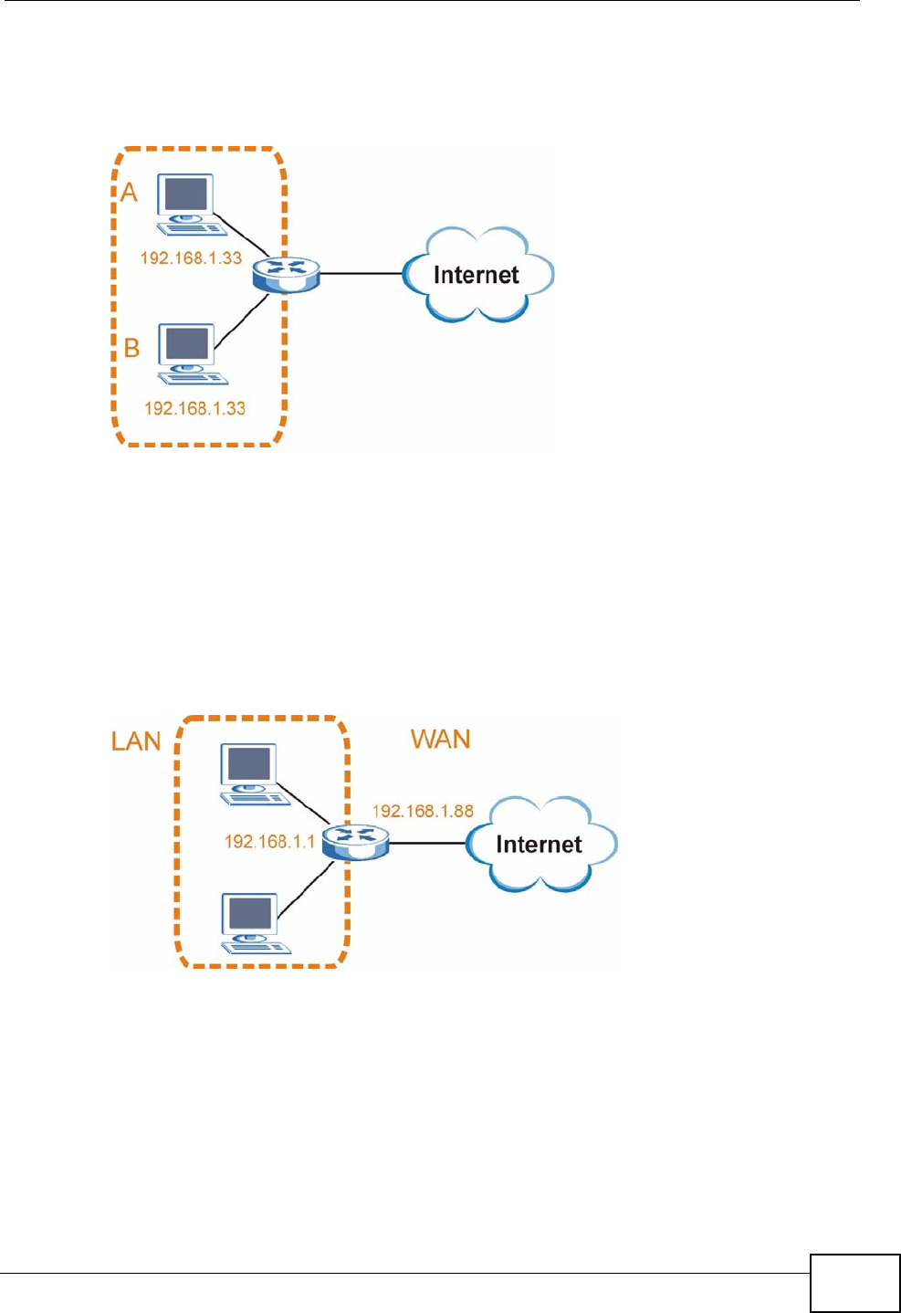
Appendix C IP Addresses and Subnetting
P-2612HWU-F1 User’s Guide 531
address to computer A or setting computer A to obtain an IP address
automatically.
Figure 360 Conflicting Computer IP Addresses Example
Conflicting Router IP Addresses Example
Since a router connects different networks, it must have interfaces using different
network numbers. For example, if a router is set between a LAN and the Internet
(WAN), the router’s LAN and WAN addresses must be on different subnets. In the
following example, the LAN and WAN are on the same subnet. The LAN computers
cannot access the Internet because the router cannot route between networks.
Figure 361 Conflicting Computer IP Addresses Example
Conflicting Computer and Router IP Addresses Example
More than one device can not use the same IP address. In the following example,
the computer and the router’s LAN port both use 192.168.1.1 as the IP address.
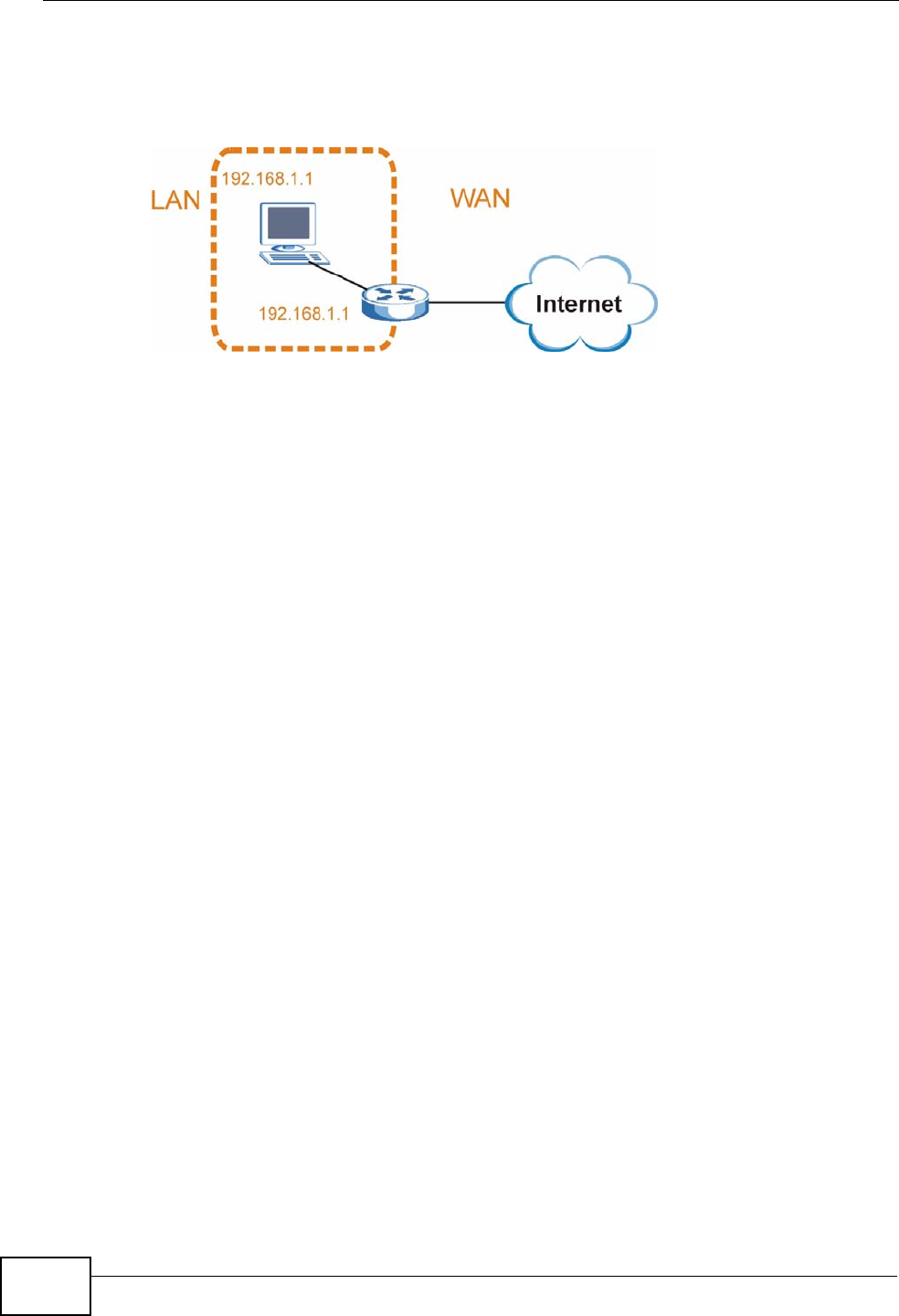
Appendix C IP Addresses and Subnetting
P-2612HWU-F1 User’s Guide
532
The computer cannot access the Internet. This problem can be solved by
assigning a different IP address to the computer or the router’s LAN port.
Figure 362 Conflicting Computer and Router IP Addresses Example

P-2612HWU-F1 User’s Guide 533
APPENDIX D
Wireless LANs
Wireless LAN Topologies
This section discusses ad-hoc and infrastructure wireless LAN topologies.
Ad-hoc Wireless LAN Configuration
The simplest WLAN configuration is an independent (Ad-hoc) WLAN that connects
a set of computers with wireless adapters (A, B, C). Any time two or more wireless
adapters are within range of each other, they can set up an independent network,
which is commonly referred to as an ad-hoc network or Independent Basic Service
Set (IBSS). The following diagram shows an example of notebook computers
using wireless adapters to form an ad-hoc wireless LAN.
Figure 363 Peer-to-Peer Communication in an Ad-hoc Network
BSS
A Basic Service Set (BSS) exists when all communications between wireless
clients or between a wireless client and a wired network client go through one
access point (AP).
Intra-BSS traffic is traffic between wireless clients in the BSS. When Intra-BSS is
enabled, wireless client A and B can access the wired network and communicate
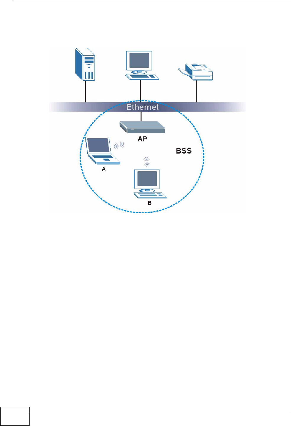
Appendix D Wireless LANs
P-2612HWU-F1 User’s Guide
534
with each other. When Intra-BSS is disabled, wireless client A and B can still
access the wired network but cannot communicate with each other.
Figure 364 Basic Service Set
ESS
An Extended Service Set (ESS) consists of a series of overlapping BSSs, each
containing an access point, with each access point connected together by a wired
network. This wired connection between APs is called a Distribution System (DS).
This type of wireless LAN topology is called an Infrastructure WLAN. The Access
Points not only provide communication with the wired network but also mediate
wireless network traffic in the immediate neighborhood.
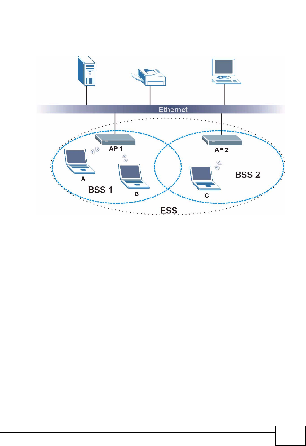
Appendix D Wireless LANs
P-2612HWU-F1 User’s Guide 535
An ESSID (ESS IDentification) uniquely identifies each ESS. All access points and
their associated wireless clients within the same ESS must have the same ESSID
in order to communicate.
Figure 365 Infrastructure WLAN
Channel
A channel is the radio frequency(ies) used by wireless devices to transmit and
receive data. Channels available depend on your geographical area. You may have
a choice of channels (for your region) so you should use a channel different from
an adjacent AP (access point) to reduce interference. Interference occurs when
radio signals from different access points overlap causing interference and
degrading performance.
Adjacent channels partially overlap however. To avoid interference due to overlap,
your AP should be on a channel at least five channels away from a channel that an
adjacent AP is using. For example, if your region has 11 channels and an adjacent
AP is using channel 1, then you need to select a channel between 6 or 11.
RTS/CTS
A hidden node occurs when two stations are within range of the same access
point, but are not within range of each other. The following figure illustrates a
hidden node. Both stations (STA) are within range of the access point (AP) or
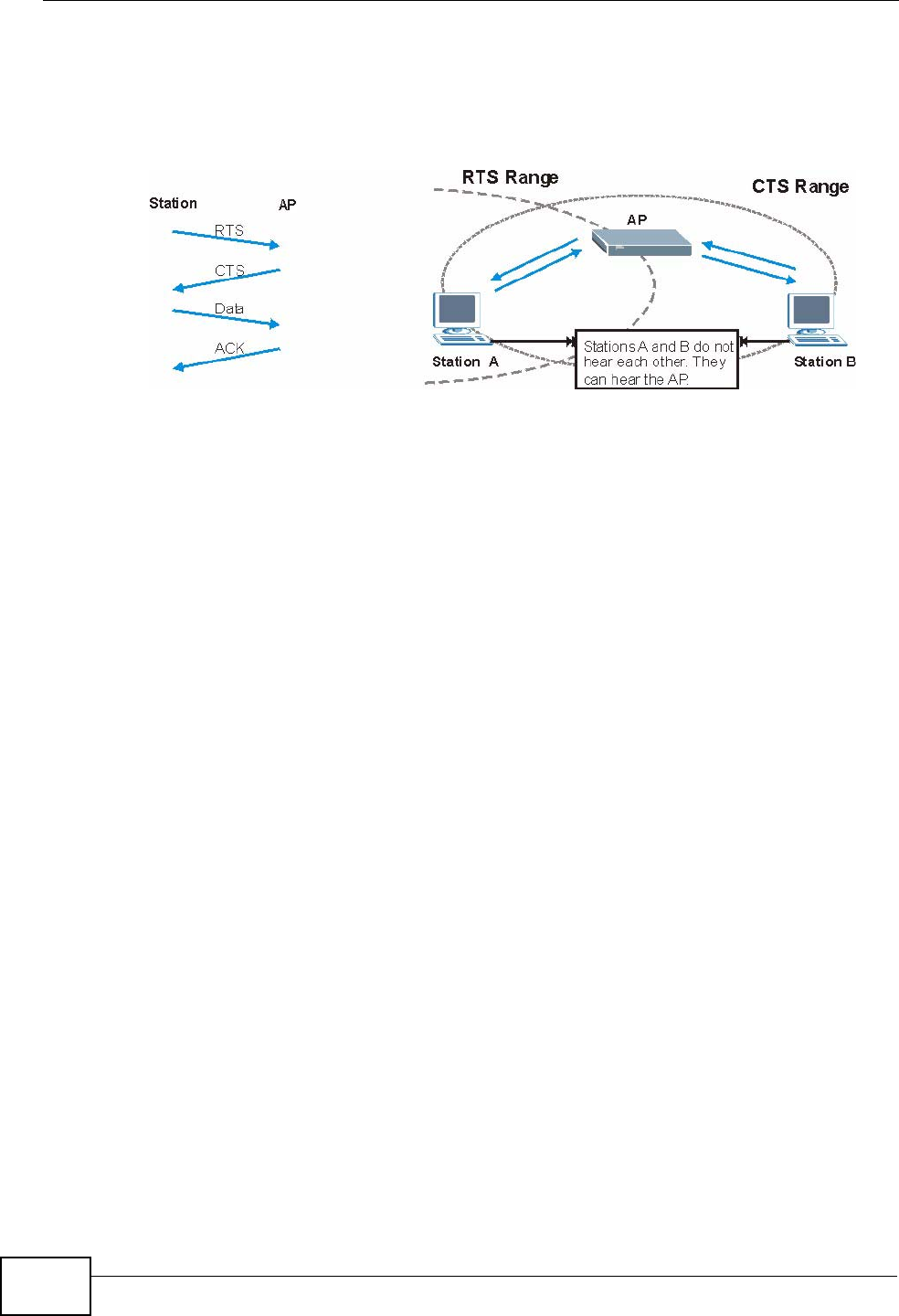
Appendix D Wireless LANs
P-2612HWU-F1 User’s Guide
536
wireless gateway, but out-of-range of each other, so they cannot "hear" each
other, that is they do not know if the channel is currently being used. Therefore,
they are considered hidden from each other.
Figure 366 RTS/CTS
When station A sends data to the AP, it might not know that the station B is
already using the channel. If these two stations send data at the same time,
collisions may occur when both sets of data arrive at the AP at the same time,
resulting in a loss of messages for both stations.
RTS/CTS is designed to prevent collisions due to hidden nodes. An RTS/CTS
defines the biggest size data frame you can send before an RTS (Request To
Send)/CTS (Clear to Send) handshake is invoked.
When a data frame exceeds the RTS/CTS value you set (between 0 to 2432
bytes), the station that wants to transmit this frame must first send an RTS
(Request To Send) message to the AP for permission to send it. The AP then
responds with a CTS (Clear to Send) message to all other stations within its range
to notify them to defer their transmission. It also reserves and confirms with the
requesting station the time frame for the requested transmission.
Stations can send frames smaller than the specified RTS/CTS directly to the AP
without the RTS (Request To Send)/CTS (Clear to Send) handshake.
You should only configure RTS/CTS if the possibility of hidden nodes exists on
your network and the "cost" of resending large frames is more than the extra
network overhead involved in the RTS (Request To Send)/CTS (Clear to Send)
handshake.
If the RTS/CTS value is greater than the Fragmentation Threshold value (see
next), then the RTS (Request To Send)/CTS (Clear to Send) handshake will never
occur as data frames will be fragmented before they reach RTS/CTS size.
Note: Enabling the RTS Threshold causes redundant network overhead that could
negatively affect the throughput performance instead of providing a remedy.

Appendix D Wireless LANs
P-2612HWU-F1 User’s Guide 537
Fragmentation Threshold
A Fragmentation Threshold is the maximum data fragment size (between 256
and 2432 bytes) that can be sent in the wireless network before the AP will
fragment the packet into smaller data frames.
A large Fragmentation Threshold is recommended for networks not prone to
interference while you should set a smaller threshold for busy networks or
networks that are prone to interference.
If the Fragmentation Threshold value is smaller than the RTS/CTS value (see
previously) you set then the RTS (Request To Send)/CTS (Clear to Send)
handshake will never occur as data frames will be fragmented before they reach
RTS/CTS size.
Preamble Type
Preamble is used to signal that data is coming to the receiver. Short and long refer
to the length of the synchronization field in a packet.
Short preamble increases performance as less time sending preamble means
more time for sending data. All IEEE 802.11 compliant wireless adapters support
long preamble, but not all support short preamble.
Use long preamble if you are unsure what preamble mode other wireless devices
on the network support, and to provide more reliable communications in busy
wireless networks.
Use short preamble if you are sure all wireless devices on the network support it,
and to provide more efficient communications.
Use the dynamic setting to automatically use short preamble when all wireless
devices on the network support it, otherwise the ZyXEL Device uses long
preamble.
Note: The wireless devices MUST use the same preamble mode in order to
communicate.
IEEE 802.11g Wireless LAN
IEEE 802.11g is fully compatible with the IEEE 802.11b standard. This means an
IEEE 802.11b adapter can interface directly with an IEEE 802.11g access point
(and vice versa) at 11 Mbps or lower depending on range. IEEE 802.11g has
Appendix D Wireless LANs
P-2612HWU-F1 User’s Guide
538
several intermediate rate steps between the maximum and minimum data rates.
The IEEE 802.11g data rate and modulation are as follows:
Wireless Security Overview
Wireless security is vital to your network to protect wireless communication
between wireless clients, access points and the wired network.
Wireless security methods available on the ZyXEL Device are data encryption,
wireless client authentication, restricting access by device MAC address and hiding
the ZyXEL Device identity.
The following figure shows the relative effectiveness of these wireless security
methods available on your ZyXEL Device.
Note: You must enable the same wireless security settings on the ZyXEL Device and
on all wireless clients that you want to associate with it.
Table 183 IEEE 802.11g
DATA RATE
(MBPS) MODULATION
1 DBPSK (Differential Binary Phase Shift Keyed)
2 DQPSK (Differential Quadrature Phase Shift Keying)
5.5 / 11 CCK (Complementary Code Keying)
6/9/12/18/24/36/
48/54 OFDM (Orthogonal Frequency Division Multiplexing)
Table 184 Wireless Security Levels
SECURITY
LEVEL SECURITY TYPE
Least
Secure
Most Secure
Unique SSID (Default)
Unique SSID with Hide SSID Enabled
MAC Address Filtering
WEP Encryption
IEEE802.1x EAP with RADIUS Server
Authentication
Wi-Fi Protected Access (WPA)
WPA2

Appendix D Wireless LANs
P-2612HWU-F1 User’s Guide 539
IEEE 802.1x
In June 2001, the IEEE 802.1x standard was designed to extend the features of
IEEE 802.11 to support extended authentication as well as providing additional
accounting and control features. It is supported by Windows XP and a number of
network devices. Some advantages of IEEE 802.1x are:
• User based identification that allows for roaming.
• Support for RADIUS (Remote Authentication Dial In User Service, RFC 2138,
2139) for centralized user profile and accounting management on a network
RADIUS server.
• Support for EAP (Extensible Authentication Protocol, RFC 2486) that allows
additional authentication methods to be deployed with no changes to the access
point or the wireless clients.
RADIUS
RADIUS is based on a client-server model that supports authentication,
authorization and accounting. The access point is the client and the server is the
RADIUS server. The RADIUS server handles the following tasks:
• Authentication
Determines the identity of the users.
• Authorization
Determines the network services available to authenticated users once they are
connected to the network.
•Accounting
Keeps track of the client’s network activity.
RADIUS is a simple package exchange in which your AP acts as a message relay
between the wireless client and the network RADIUS server.
Types of RADIUS Messages
The following types of RADIUS messages are exchanged between the access point
and the RADIUS server for user authentication:
• Access-Request
Sent by an access point requesting authentication.
• Access-Reject
Sent by a RADIUS server rejecting access.
• Access-Accept
Sent by a RADIUS server allowing access.

Appendix D Wireless LANs
P-2612HWU-F1 User’s Guide
540
• Access-Challenge
Sent by a RADIUS server requesting more information in order to allow access.
The access point sends a proper response from the user and then sends another
Access-Request message.
The following types of RADIUS messages are exchanged between the access point
and the RADIUS server for user accounting:
•Accounting-Request
Sent by the access point requesting accounting.
• Accounting-Response
Sent by the RADIUS server to indicate that it has started or stopped accounting.
In order to ensure network security, the access point and the RADIUS server use a
shared secret key, which is a password, they both know. The key is not sent over
the network. In addition to the shared key, password information exchanged is
also encrypted to protect the network from unauthorized access.
Types of EAP Authentication
This section discusses some popular authentication types: EAP-MD5, EAP-TLS,
EAP-TTLS, PEAP and LEAP. Your wireless LAN device may not support all
authentication types.
EAP (Extensible Authentication Protocol) is an authentication protocol that runs on
top of the IEEE 802.1x transport mechanism in order to support multiple types of
user authentication. By using EAP to interact with an EAP-compatible RADIUS
server, an access point helps a wireless station and a RADIUS server perform
authentication.
The type of authentication you use depends on the RADIUS server and an
intermediary AP(s) that supports IEEE 802.1x. .
For EAP-TLS authentication type, you must first have a wired connection to the
network and obtain the certificate(s) from a certificate authority (CA). A certificate
(also called digital IDs) can be used to authenticate users and a CA issues
certificates and guarantees the identity of each certificate owner.
EAP-MD5 (Message-Digest Algorithm 5)
MD5 authentication is the simplest one-way authentication method. The
authentication server sends a challenge to the wireless client. The wireless client
‘proves’ that it knows the password by encrypting the password with the challenge
and sends back the information. Password is not sent in plain text.

Appendix D Wireless LANs
P-2612HWU-F1 User’s Guide 541
However, MD5 authentication has some weaknesses. Since the authentication
server needs to get the plaintext passwords, the passwords must be stored. Thus
someone other than the authentication server may access the password file. In
addition, it is possible to impersonate an authentication server as MD5
authentication method does not perform mutual authentication. Finally, MD5
authentication method does not support data encryption with dynamic session
key. You must configure WEP encryption keys for data encryption.
EAP-TLS (Transport Layer Security)
With EAP-TLS, digital certifications are needed by both the server and the wireless
clients for mutual authentication. The server presents a certificate to the client.
After validating the identity of the server, the client sends a different certificate to
the server. The exchange of certificates is done in the open before a secured
tunnel is created. This makes user identity vulnerable to passive attacks. A digital
certificate is an electronic ID card that authenticates the sender’s identity.
However, to implement EAP-TLS, you need a Certificate Authority (CA) to handle
certificates, which imposes a management overhead.
EAP-TTLS (Tunneled Transport Layer Service)
EAP-TTLS is an extension of the EAP-TLS authentication that uses certificates for
only the server-side authentications to establish a secure connection. Client
authentication is then done by sending username and password through the
secure connection, thus client identity is protected. For client authentication, EAP-
TTLS supports EAP methods and legacy authentication methods such as PAP,
CHAP, MS-CHAP and MS-CHAP v2.
PEAP (Protected EAP)
Like EAP-TTLS, server-side certificate authentication is used to establish a secure
connection, then use simple username and password methods through the
secured connection to authenticate the clients, thus hiding client identity.
However, PEAP only supports EAP methods, such as EAP-MD5, EAP-MSCHAPv2
and EAP-GTC (EAP-Generic Token Card), for client authentication. EAP-GTC is
implemented only by Cisco.
LEAP
LEAP (Lightweight Extensible Authentication Protocol) is a Cisco implementation of
IEEE 802.1x.

Appendix D Wireless LANs
P-2612HWU-F1 User’s Guide
542
Dynamic WEP Key Exchange
The AP maps a unique key that is generated with the RADIUS server. This key
expires when the wireless connection times out, disconnects or reauthentication
times out. A new WEP key is generated each time reauthentication is performed.
If this feature is enabled, it is not necessary to configure a default encryption key
in the wireless security configuration screen. You may still configure and store
keys, but they will not be used while dynamic WEP is enabled.
Note: EAP-MD5 cannot be used with Dynamic WEP Key Exchange
For added security, certificate-based authentications (EAP-TLS, EAP-TTLS and
PEAP) use dynamic keys for data encryption. They are often deployed in corporate
environments, but for public deployment, a simple user name and password pair
is more practical. The following table is a comparison of the features of
authentication types.
WPA and WPA2
Wi-Fi Protected Access (WPA) is a subset of the IEEE 802.11i standard. WPA2
(IEEE 802.11i) is a wireless security standard that defines stronger encryption,
authentication and key management than WPA.
Key differences between WPA or WPA2 and WEP are improved data encryption and
user authentication.
If both an AP and the wireless clients support WPA2 and you have an external
RADIUS server, use WPA2 for stronger data encryption. If you don't have an
external RADIUS server, you should use WPA2-PSK (WPA2-Pre-Shared Key) that
only requires a single (identical) password entered into each access point, wireless
gateway and wireless client. As long as the passwords match, a wireless client will
be granted access to a WLAN.
Table 185 Comparison of EAP Authentication Types
EAP-MD5 EAP-TLS EAP-TTLS PEAP LEAP
Mutual Authentication No Yes Yes Yes Yes
Certificate – Client No Yes Optional Optional No
Certificate – Server No Yes Yes Yes No
Dynamic Key Exchange No Yes Yes Yes Yes
Credential Integrity None Strong Strong Strong Moderate
Deployment Difficulty Easy Hard Moderate Moderate Moderate
Client Identity
Protection No No Yes Yes No

Appendix D Wireless LANs
P-2612HWU-F1 User’s Guide 543
If the AP or the wireless clients do not support WPA2, just use WPA or WPA-PSK
depending on whether you have an external RADIUS server or not.
Select WEP only when the AP and/or wireless clients do not support WPA or WPA2.
WEP is less secure than WPA or WPA2.
Encryption
Both WPA and WPA2 improve data encryption by using Temporal Key Integrity
Protocol (TKIP), Message Integrity Check (MIC) and IEEE 802.1x. WPA and WPA2
use Advanced Encryption Standard (AES) in the Counter mode with Cipher block
chaining Message authentication code Protocol (CCMP) to offer stronger
encryption than TKIP.
TKIP uses 128-bit keys that are dynamically generated and distributed by the
authentication server. AES (Advanced Encryption Standard) is a block cipher that
uses a 256-bit mathematical algorithm called Rijndael. They both include a per-
packet key mixing function, a Message Integrity Check (MIC) named Michael, an
extended initialization vector (IV) with sequencing rules, and a re-keying
mechanism.
WPA and WPA2 regularly change and rotate the encryption keys so that the same
encryption key is never used twice.
The RADIUS server distributes a Pairwise Master Key (PMK) key to the AP that
then sets up a key hierarchy and management system, using the PMK to
dynamically generate unique data encryption keys to encrypt every data packet
that is wirelessly communicated between the AP and the wireless clients. This all
happens in the background automatically.
The Message Integrity Check (MIC) is designed to prevent an attacker from
capturing data packets, altering them and resending them. The MIC provides a
strong mathematical function in which the receiver and the transmitter each
compute and then compare the MIC. If they do not match, it is assumed that the
data has been tampered with and the packet is dropped.
By generating unique data encryption keys for every data packet and by creating
an integrity checking mechanism (MIC), with TKIP and AES it is more difficult to
decrypt data on a Wi-Fi network than WEP and difficult for an intruder to break
into the network.
The encryption mechanisms used for WPA(2) and WPA(2)-PSK are the same. The
only difference between the two is that WPA(2)-PSK uses a simple common
password, instead of user-specific credentials. The common-password approach
makes WPA(2)-PSK susceptible to brute-force password-guessing attacks but it’s
still an improvement over WEP as it employs a consistent, single, alphanumeric
password to derive a PMK which is used to generate unique temporal encryption

Appendix D Wireless LANs
P-2612HWU-F1 User’s Guide
544
keys. This prevent all wireless devices sharing the same encryption keys. (a
weakness of WEP)
User Authentication
WPA and WPA2 apply IEEE 802.1x and Extensible Authentication Protocol (EAP) to
authenticate wireless clients using an external RADIUS database. WPA2 reduces
the number of key exchange messages from six to four (CCMP 4-way handshake)
and shortens the time required to connect to a network. Other WPA2
authentication features that are different from WPA include key caching and pre-
authentication. These two features are optional and may not be supported in all
wireless devices.
Key caching allows a wireless client to store the PMK it derived through a
successful authentication with an AP. The wireless client uses the PMK when it tries
to connect to the same AP and does not need to go with the authentication
process again.
Pre-authentication enables fast roaming by allowing the wireless client (already
connecting to an AP) to perform IEEE 802.1x authentication with another AP
before connecting to it.
Wireless Client WPA Supplicants
A wireless client supplicant is the software that runs on an operating system
instructing the wireless client how to use WPA. At the time of writing, the most
widely available supplicant is the WPA patch for Windows XP, Funk Software's
Odyssey client.
The Windows XP patch is a free download that adds WPA capability to Windows
XP's built-in "Zero Configuration" wireless client. However, you must run Windows
XP to use it.
WPA(2) with RADIUS Application Example
To set up WPA(2), you need the IP address of the RADIUS server, its port number
(default is 1812), and the RADIUS shared secret. A WPA(2) application example
with an external RADIUS server looks as follows. "A" is the RADIUS server. "DS" is
the distribution system.
1The AP passes the wireless client's authentication request to the RADIUS server.
2The RADIUS server then checks the user's identification against its database and
grants or denies network access accordingly.
3A 256-bit Pairwise Master Key (PMK) is derived from the authentication process by
the RADIUS server and the client.
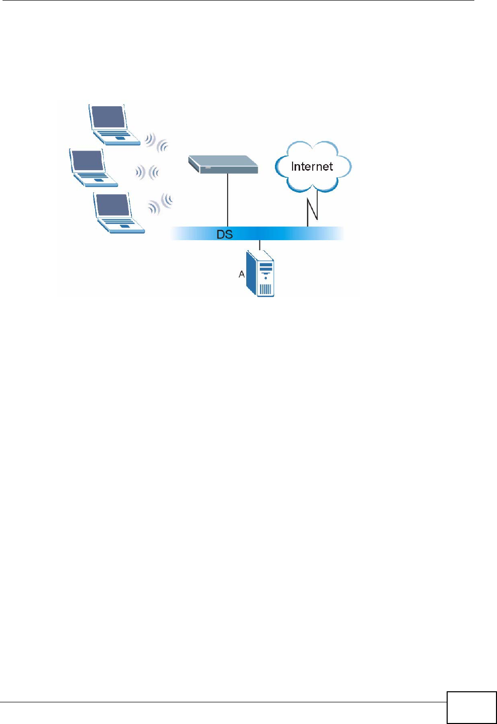
Appendix D Wireless LANs
P-2612HWU-F1 User’s Guide 545
4The RADIUS server distributes the PMK to the AP. The AP then sets up a key
hierarchy and management system, using the PMK to dynamically generate
unique data encryption keys. The keys are used to encrypt every data packet that
is wirelessly communicated between the AP and the wireless clients.
Figure 367 WPA(2) with RADIUS Application Example
WPA(2)-PSK Application Example
A WPA(2)-PSK application looks as follows.
1First enter identical passwords into the AP and all wireless clients. The Pre-Shared
Key (PSK) must consist of between 8 and 63 ASCII characters or 64 hexadecimal
characters (including spaces and symbols).
2The AP checks each wireless client's password and allows it to join the network
only if the password matches.
3The AP and wireless clients generate a common PMK (Pairwise Master Key). The
key itself is not sent over the network, but is derived from the PSK and the SSID.
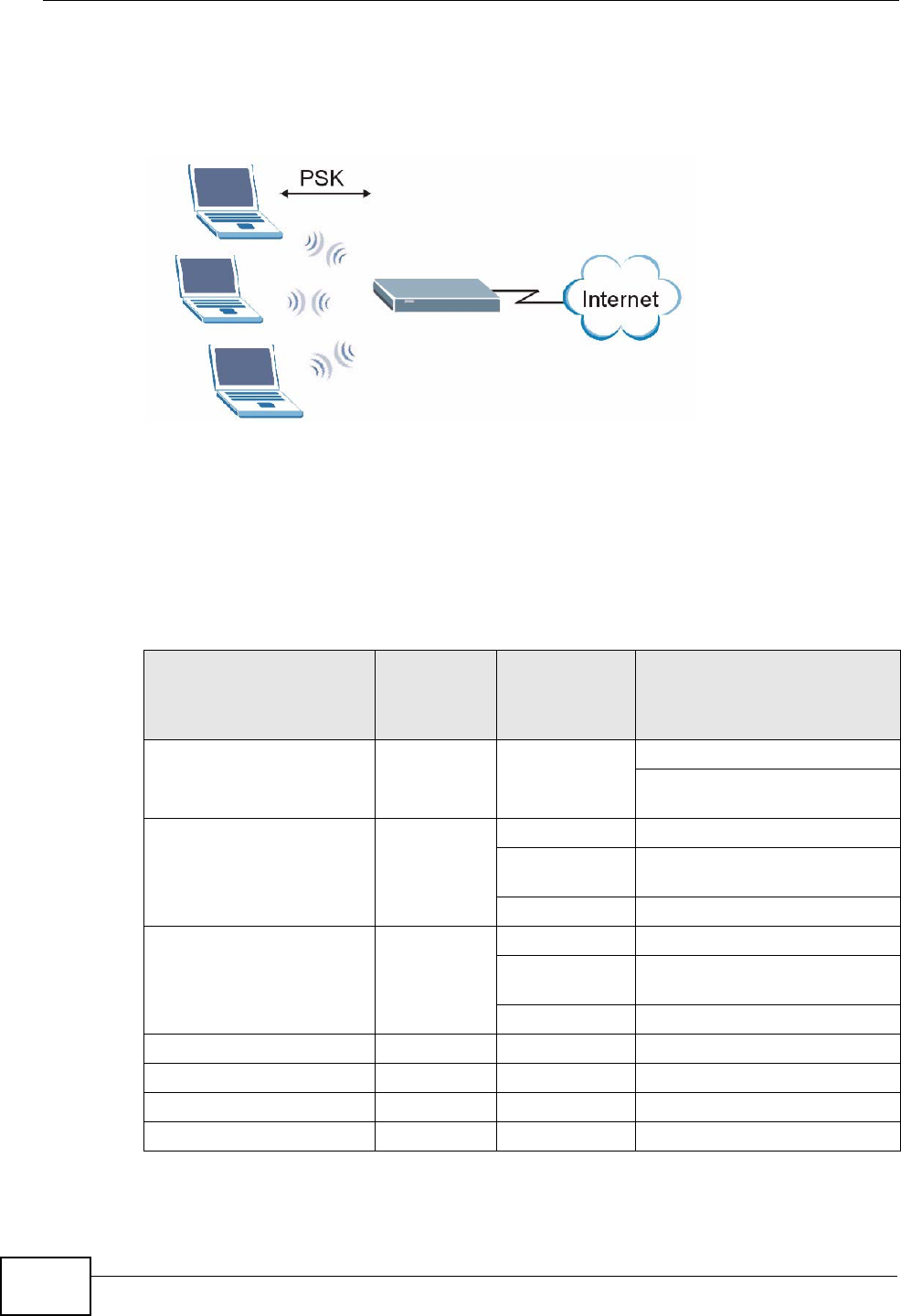
Appendix D Wireless LANs
P-2612HWU-F1 User’s Guide
546
4The AP and wireless clients use the TKIP or AES encryption process, the PMK and
information exchanged in a handshake to create temporal encryption keys. They
use these keys to encrypt data exchanged between them.
Figure 368 WPA(2)-PSK Authentication
Security Parameters Summary
Refer to this table to see what other security parameters you should configure for
each authentication method or key management protocol type. MAC address
filters are not dependent on how you configure these security features.
Table 186 Wireless Security Relational Matrix
AUTHENTICATION
METHOD/ KEY
MANAGEMENT
PROTOCOL
ENCRYPTIO
N METHOD ENTER
MANUAL KEY IEEE 802.1X
Open None No Disable
Enable without Dynamic WEP
Key
Open WEP No Enable with Dynamic WEP Key
Yes Enable without Dynamic WEP
Key
Yes Disable
Shared WEP No Enable with Dynamic WEP Key
Yes Enable without Dynamic WEP
Key
Yes Disable
WPA TKIP/AES No Enable
WPA-PSK TKIP/AES Yes Disable
WPA2 TKIP/AES No Enable
WPA2-PSK TKIP/AES Yes Disable

Appendix D Wireless LANs
P-2612HWU-F1 User’s Guide 547
Antenna Overview
An antenna couples RF signals onto air. A transmitter within a wireless device
sends an RF signal to the antenna, which propagates the signal through the air.
The antenna also operates in reverse by capturing RF signals from the air.
Positioning the antennas properly increases the range and coverage area of a
wireless LAN.
Antenna Characteristics
Frequency
An antenna in the frequency of 2.4GHz (IEEE 802.11b and IEEE 802.11g) or 5GHz
(IEEE 802.11a) is needed to communicate efficiently in a wireless LAN
Radiation Pattern
A radiation pattern is a diagram that allows you to visualize the shape of the
antenna’s coverage area.
Antenna Gain
Antenna gain, measured in dB (decibel), is the increase in coverage within the RF
beam width. Higher antenna gain improves the range of the signal for better
communications.
For an indoor site, each 1 dB increase in antenna gain results in a range increase
of approximately 2.5%. For an unobstructed outdoor site, each 1dB increase in
gain results in a range increase of approximately 5%. Actual results may vary
depending on the network environment.
Antenna gain is sometimes specified in dBi, which is how much the antenna
increases the signal power compared to using an isotropic antenna. An isotropic
antenna is a theoretical perfect antenna that sends out radio signals equally well
in all directions. dBi represents the true gain that the antenna provides.
Types of Antennas for WLAN
There are two types of antennas used for wireless LAN applications.

Appendix D Wireless LANs
P-2612HWU-F1 User’s Guide
548
• Omni-directional antennas send the RF signal out in all directions on a horizontal
plane. The coverage area is torus-shaped (like a donut) which makes these
antennas ideal for a room environment. With a wide coverage area, it is possible
to make circular overlapping coverage areas with multiple access points.
• Directional antennas concentrate the RF signal in a beam, like a flashlight does
with the light from its bulb. The angle of the beam determines the width of the
coverage pattern. Angles typically range from 20 degrees (very directional) to
120 degrees (less directional). Directional antennas are ideal for hallways and
outdoor point-to-point applications.
Positioning Antennas
In general, antennas should be mounted as high as practically possible and free of
obstructions. In point-to–point application, position both antennas at the same
height and in a direct line of sight to each other to attain the best performance.
For omni-directional antennas mounted on a table, desk, and so on, point the
antenna up. For omni-directional antennas mounted on a wall or ceiling, point the
antenna down. For a single AP application, place omni-directional antennas as
close to the center of the coverage area as possible.
For directional antennas, point the antenna in the direction of the desired
coverage area.
WiFi Protected Setup
Your ZyXEL Device supports WiFi Protected Setup (WPS), which is an easy way to
set up a secure wireless network. WPS is an industry standard specification,
defined by the WiFi Alliance.
WPS allows you to quickly set up a wireless network with strong security, without
having to configure security settings manually. Each WPS connection works
between two devices. Both devices must support WPS (check each device’s
documentation to make sure).
Depending on the devices you have, you can either press a button (on the device
itself, or in its configuration utility) or enter a PIN (a unique Personal Identification
Number that allows one device to authenticate the other) in each of the two
devices. When WPS is activated on a device, it has two minutes to find another
device that also has WPS activated. Then, the two devices connect and set up a
secure network by themselves.

Appendix D Wireless LANs
P-2612HWU-F1 User’s Guide 549
Push Button Configuration
WPS Push Button Configuration (PBC) is initiated by pressing a button on each
WPS-enabled device, and allowing them to connect automatically. You do not need
to enter any information.
Not every WPS-enabled device has a physical WPS button. Some may have a WPS
PBC button in their configuration utilities instead of or in addition to the physical
button.
Take the following steps to set up WPS using the button.
1Ensure that the two devices you want to set up are within wireless range of one
another.
2Look for a WPS button on each device. If the device does not have one, log into its
configuration utility and locate the button (see the device’s User’s Guide for how to
do this - for the ZyXEL Device, see Section 8.6 on page 149).
3Press the button on one of the devices (it doesn’t matter which).
4Within two minutes, press the button on the other device. The registrar sends the
network name (SSID) and security key through an secure connection to the
enrollee.
If you need to make sure that WPS worked, check the list of associated wireless
clients in the AP’s configuration utility. If you see the wireless client in the list,
WPS was successful.
PIN Configuration
Each WPS-enabled device has its own PIN (Personal Identification Number). This
may either be static (it cannot be changed) or dynamic (you can change it to a
new random number by clicking on a button in the configuration interface).
When you use the PIN method, you must enter the enrollee’s PIN into the
registrar. Then, when WPS is activated on the enrollee, it presents its PIN to the
registrar. If the PIN matches, the registrar sends the network and security
information to the enrollee, allowing it to join the network.
The advantage of using the PIN method rather than the PBC method is that you
can ensure that the connection is established between the devices you specify, not
just the first two devices to activate WPS in the area. However, you need to log
into the configuration interfaces of both devices.
Take the following steps to set up WPS using the PIN method.

Appendix D Wireless LANs
P-2612HWU-F1 User’s Guide
550
1Decide which device you want to be the registrar (usually the AP) and which you
want to be the enrollee (usually the client).
2Look for the enrollee’s WPS PIN; it may be displayed on the device. If you don’t
see it, log into the enrollee’s configuration interface and locate the PIN. Select the
PIN connection mode (not PBC connection mode). See the device’s User’s Guide
for how to do this - for the ZyXEL Device, see Section 8.5 on page 148.
3Log into the configuration utility of the registrar. Select the PIN connection mode
(not the PBC connection mode). Locate the place where you can enter the
enrollee’s PIN (if you are using the ZyXEL Device, see Section 8.6 on page 149).
Enter the PIN from the enrollee device.
4Activate WPS on both devices within two minutes.
Note: Use the configuration utility to activate WPS, not the push-button on the device
itself.
5On a computer connected to the wireless client, try to connect to the Internet. If
you can connect, WPS was successful.
If you cannot connect, check the list of associated wireless clients in the AP’s
configuration utility. If you see the wireless client in the list, WPS was successful.
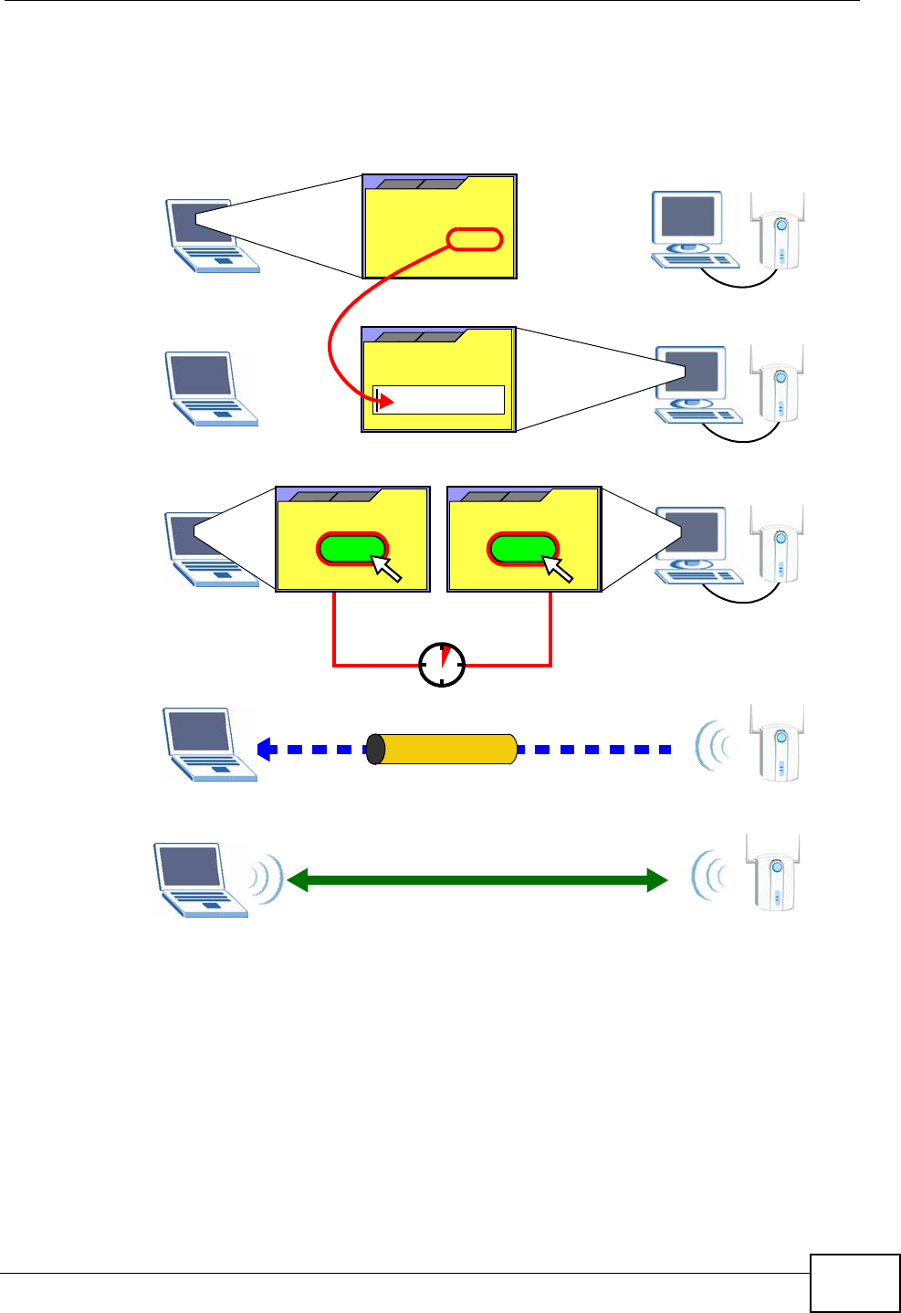
Appendix D Wireless LANs
P-2612HWU-F1 User’s Guide 551
The following figure shows a WPS-enabled wireless client (installed in a notebook
computer) connecting to the WPS-enabled AP via the PIN method.
Figure 369 Example WPS Process: PIN Method
How WPS Works
When two WPS-enabled devices connect, each device must assume a specific role.
One device acts as the registrar (the device that supplies network and security
settings) and the other device acts as the enrollee (the device that receives
network and security settings. The registrar creates a secure EAP (Extensible
Authentication Protocol) tunnel and sends the network name (SSID) and the WPA-
PSK or WPA2-PSK pre-shared key to the enrollee. Whether WPA-PSK or WPA2-PSK
is used depends on the standards supported by the devices. If the registrar is
ENROLLEE
SECURE EAP TUNNEL
SSID
WPA(2)-PSK
WITHIN 2 MINUTES
COMMUNICATION
This device’s
WPS
Enter WPS PIN
WPS
from other device:
WPS PIN: 123456
WPS
START
WPS
START
REGISTRAR
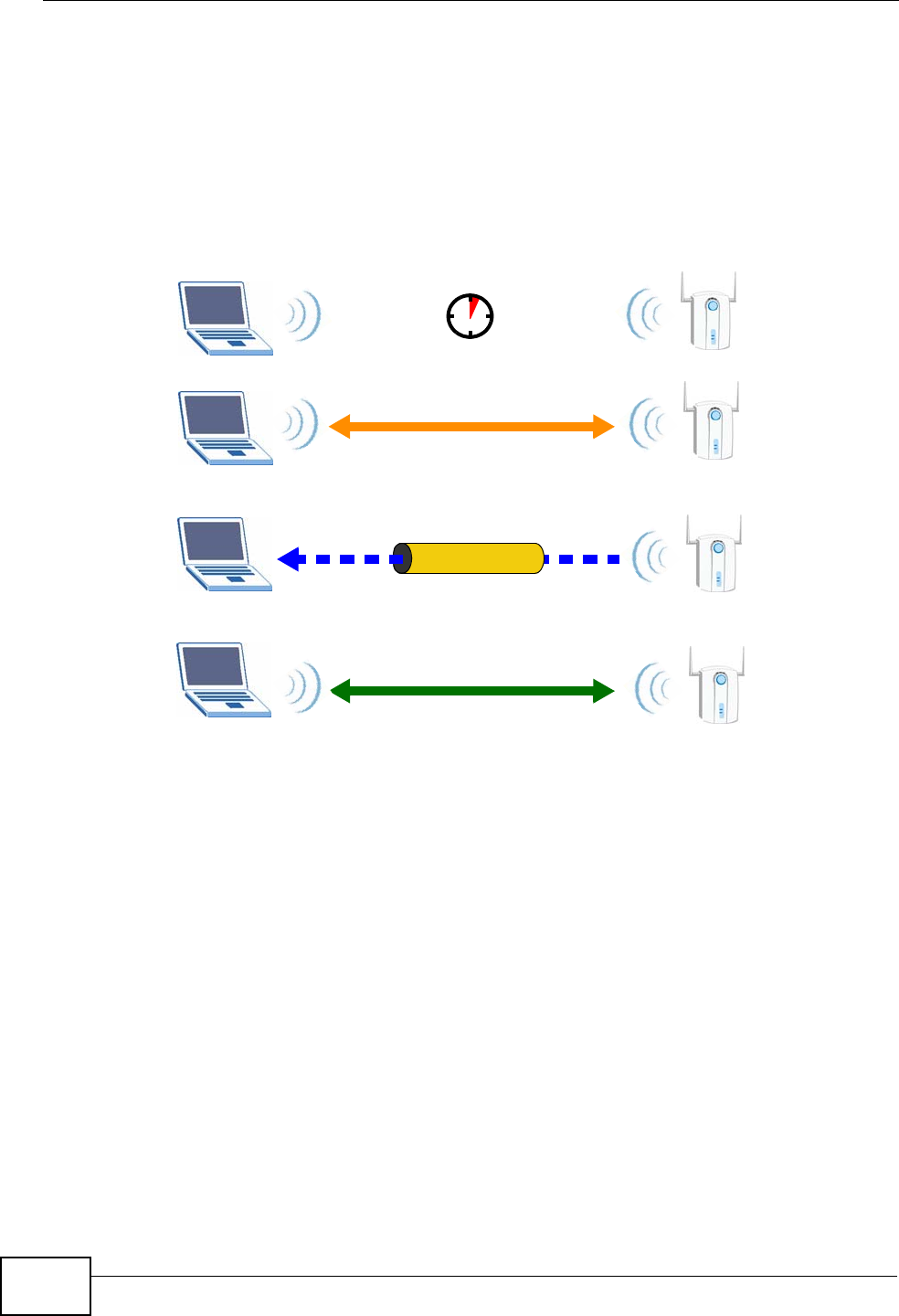
Appendix D Wireless LANs
P-2612HWU-F1 User’s Guide
552
already part of a network, it sends the existing information. If not, it generates
the SSID and WPA(2)-PSK randomly.
The following figure shows a WPS-enabled client (installed in a notebook
computer) connecting to a WPS-enabled access point.
Figure 370 How WPS works
The roles of registrar and enrollee last only as long as the WPS setup process is
active (two minutes). The next time you use WPS, a different device can be the
registrar if necessary.
The WPS connection process is like a handshake; only two devices participate in
each WPS transaction. If you want to add more devices you should repeat the
process with one of the existing networked devices and the new device.
Note that the access point (AP) is not always the registrar, and the wireless client
is not always the enrollee. All WPS-certified APs can be a registrar, and so can
some WPS-enabled wireless clients.
By default, a WPS devices is “unconfigured”. This means that it is not part of an
existing network and can act as either enrollee or registrar (if it supports both
functions). If the registrar is unconfigured, the security settings it transmits to the
enrollee are randomly-generated. Once a WPS-enabled device has connected to
another device using WPS, it becomes “configured”. A configured wireless client
can still act as enrollee or registrar in subsequent WPS connections, but a
configured access point can no longer act as enrollee. It will be the registrar in all
SECURE TUNNEL
SECURITY INFO
WITHIN 2 MINUTES
COMMUNICATION
ACTIVATE
WPS
ACTIVATE
WPS
WPS HANDSHAKE
REGISTRARENROLLEE
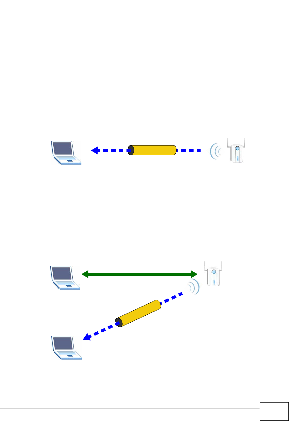
Appendix D Wireless LANs
P-2612HWU-F1 User’s Guide 553
subsequent WPS connections in which it is involved. If you want a configured AP to
act as an enrollee, you must reset it to its factory defaults.
Example WPS Network Setup
This section shows how security settings are distributed in an example WPS setup.
The following figure shows an example network. In step 1, both AP1 and Client 1
are unconfigured. When WPS is activated on both, they perform the handshake. In
this example, AP1 is the registrar, and Client 1 is the enrollee. The registrar
randomly generates the security information to set up the network, since it is
unconfigured and has no existing information.
Figure 371 WPS: Example Network Step 1
In step 2, you add another wireless client to the network. You know that Client 1
supports registrar mode, but it is better to use AP1 for the WPS handshake with
the new client since you must connect to the access point anyway in order to use
the network. In this case, AP1 must be the registrar, since it is configured (it
already has security information for the network). AP1 supplies the existing
security information to Client 2.
Figure 372 WPS: Example Network Step 2
REGISTRARENROLLEE
SECURITY INFO
CLIENT 1 AP1
REGISTRAR
CLIENT 1 AP1
ENROLLEE
CLIENT 2
EXISTING CONNECTION
SECURITY INFO
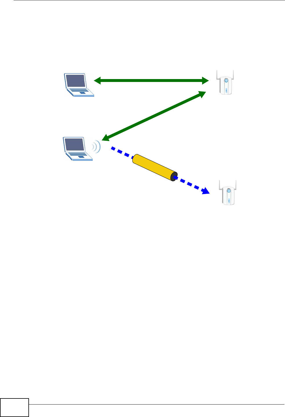
Appendix D Wireless LANs
P-2612HWU-F1 User’s Guide
554
In step 3, you add another access point (AP2) to your network. AP2 is out of
range of AP1, so you cannot use AP1 for the WPS handshake with the new access
point. However, you know that Client 2 supports the registrar function, so you use
it to perform the WPS handshake instead.
Figure 373 WPS: Example Network Step 3
Limitations of WPS
WPS has some limitations of which you should be aware.
• WPS works in Infrastructure networks only (where an AP and a wireless client
communicate). It does not work in Ad-Hoc networks (where there is no AP).
• When you use WPS, it works between two devices only. You cannot enroll
multiple devices simultaneously, you must enroll one after the other.
For instance, if you have two enrollees and one registrar you must set up the
first enrollee (by pressing the WPS button on the registrar and the first enrollee,
for example), then check that it successfully enrolled, then set up the second
device in the same way.
• WPS works only with other WPS-enabled devices. However, you can still add
non-WPS devices to a network you already set up using WPS.
WPS works by automatically issuing a randomly-generated WPA-PSK or WPA2-
PSK pre-shared key from the registrar device to the enrollee devices. Whether
the network uses WPA-PSK or WPA2-PSK depends on the device. You can check
the configuration interface of the registrar device to discover the key the
network is using (if the device supports this feature). Then, you can enter the
key into the non-WPS device and join the network as normal (the non-WPS
device must also support WPA-PSK or WPA2-PSK).
CLIENT 1 AP1
REGISTRAR
CLIENT 2
EXISTING CONNECTION
SECURITY INFO
ENROLLEE
AP1
EXISTING CONNECTION

Appendix D Wireless LANs
P-2612HWU-F1 User’s Guide 555
• When you use the PBC method, there is a short period (from the moment you
press the button on one device to the moment you press the button on the
other device) when any WPS-enabled device could join the network. This is
because the registrar has no way of identifying the “correct” enrollee, and
cannot differentiate between your enrollee and a rogue device. This is a possible
way for a hacker to gain access to a network.
You can easily check to see if this has happened. WPS works between only two
devices simultaneously, so if another device has enrolled your device will be
unable to enroll, and will not have access to the network. If this happens, open
the access point’s configuration interface and look at the list of associated
clients (usually displayed by MAC address). It does not matter if the access
point is the WPS registrar, the enrollee, or was not involved in the WPS
handshake; a rogue device must still associate with the access point to gain
access to the network. Check the MAC addresses of your wireless clients
(usually printed on a label on the bottom of the device). If there is an unknown
MAC address you can remove it or reset the AP.

Appendix D Wireless LANs
P-2612HWU-F1 User’s Guide
556

P-2612HWU-F1 User’s Guide 557
APPENDIX E
Common Services
The following table lists some commonly-used services and their associated
protocols and port numbers. For a comprehensive list of port numbers, ICMP type/
code numbers and services, visit the IANA (Internet Assigned Number Authority)
web site.
•Name: This is a short, descriptive name for the service. You can use this one or
create a different one, if you like.
•Protocol: This is the type of IP protocol used by the service. If this is TCP/
UDP, then the service uses the same port number with TCP and UDP. If this is
USER-DEFINED, the Port(s) is the IP protocol number, not the port number.
•Port(s): This value depends on the Protocol. Please refer to RFC 1700 for
further information about port numbers.
•If the Protocol is TCP, UDP, or TCP/UDP, this is the IP port number.
•If the Protocol is USER, this is the IP protocol number.
•Description: This is a brief explanation of the applications that use this service
or the situations in which this service is used.
Table 187 Commonly Used Services
NAME PROTOCOL PORT(S) DESCRIPTION
AH
(IPSEC_TUNNEL) User-Defined 51 The IPSEC AH (Authentication
Header) tunneling protocol uses this
service.
AIM/New-ICQ TCP 5190 AOL’s Internet Messenger service. It
is also used as a listening port by
ICQ.
AUTH TCP 113 Authentication protocol used by some
servers.
BGP TCP 179 Border Gateway Protocol.
BOOTP_CLIENT UDP 68 DHCP Client.
BOOTP_SERVER UDP 67 DHCP Server.
CU-SEEME TCP
UDP
7648
24032
A popular videoconferencing solution
from White Pines Software.
DNS TCP/UDP 53 Domain Name Server, a service that
matches web names (for example
www.zyxel.com) to IP numbers.

Appendix E Common Services
P-2612HWU-F1 User’s Guide
558
ESP
(IPSEC_TUNNEL) User-Defined 50 The IPSEC ESP (Encapsulation
Security Protocol) tunneling protocol
uses this service.
FINGER TCP 79 Finger is a UNIX or Internet related
command that can be used to find out
if a user is logged on.
FTP TCP
TCP
20
21
File Transfer Program, a program to
enable fast transfer of files, including
large files that may not be possible by
e-mail.
H.323 TCP 1720 NetMeeting uses this protocol.
HTTP TCP 80 Hyper Text Transfer Protocol - a
client/server protocol for the world
wide web.
HTTPS TCP 443 HTTPS is a secured http session often
used in e-commerce.
ICMP User-Defined 1Internet Control Message Protocol is
often used for diagnostic or routing
purposes.
ICQ UDP 4000 This is a popular Internet chat
program.
IGMP
(MULTICAST) User-Defined 2Internet Group Management Protocol
is used when sending packets to a
specific group of hosts.
IKE UDP 500 The Internet Key Exchange algorithm
is used for key distribution and
management.
IRC TCP/UDP 6667 This is another popular Internet chat
program.
MSN Messenger TCP 1863 Microsoft Networks’ messenger
service uses this protocol.
NEW-ICQ TCP 5190 An Internet chat program.
NEWS TCP 144 A protocol for news groups.
NFS UDP 2049 Network File System - NFS is a client/
server distributed file service that
provides transparent file sharing for
network environments.
NNTP TCP 119 Network News Transport Protocol is
the delivery mechanism for the
USENET newsgroup service.
PING User-Defined 1Packet INternet Groper is a protocol
that sends out ICMP echo requests to
test whether or not a remote host is
reachable.
POP3 TCP 110 Post Office Protocol version 3 lets a
client computer get e-mail from a
POP3 server through a temporary
connection (TCP/IP or other).
Table 187 Commonly Used Services (continued)
NAME PROTOCOL PORT(S) DESCRIPTION

Appendix E Common Services
P-2612HWU-F1 User’s Guide 559
PPTP TCP 1723 Point-to-Point Tunneling Protocol
enables secure transfer of data over
public networks. This is the control
channel.
PPTP_TUNNEL
(GRE) User-Defined 47 PPTP (Point-to-Point Tunneling
Protocol) enables secure transfer of
data over public networks. This is the
data channel.
RCMD TCP 512 Remote Command Service.
REAL_AUDIO TCP 7070 A streaming audio service that
enables real time sound over the web.
REXEC TCP 514 Remote Execution Daemon.
RLOGIN TCP 513 Remote Login.
RTELNET TCP 107 Remote Telnet.
RTSP TCP/UDP 554 The Real Time Streaming (media
control) Protocol (RTSP) is a remote
control for multimedia on the
Internet.
SFTP TCP 115 Simple File Transfer Protocol.
SMTP TCP 25 Simple Mail Transfer Protocol is the
message-exchange standard for the
Internet. SMTP enables you to move
messages from one e-mail server to
another.
SNMP TCP/UDP 161 Simple Network Management
Program.
SNMP-TRAPS TCP/UDP 162 Traps for use with the SNMP
(RFC:1215).
SQL-NET TCP 1521 Structured Query Language is an
interface to access data on many
different types of database systems,
including mainframes, midrange
systems, UNIX systems and network
servers.
SSH TCP/UDP 22 Secure Shell Remote Login Program.
STRM WORKS UDP 1558 Stream Works Protocol.
SYSLOG UDP 514 Syslog allows you to send system logs
to a UNIX server.
TACACS UDP 49 Login Host Protocol used for (Terminal
Access Controller Access Control
System).
TELNET TCP 23 Telnet is the login and terminal
emulation protocol common on the
Internet and in UNIX environments. It
operates over TCP/IP networks. Its
primary function is to allow users to
log into remote host systems.
Table 187 Commonly Used Services (continued)
NAME PROTOCOL PORT(S) DESCRIPTION

Appendix E Common Services
P-2612HWU-F1 User’s Guide
560
TFTP UDP 69 Trivial File Transfer Protocol is an
Internet file transfer protocol similar
to FTP, but uses the UDP (User
Datagram Protocol) rather than TCP
(Transmission Control Protocol).
VDOLIVE TCP 7000 Another videoconferencing solution.
Table 187 Commonly Used Services (continued)
NAME PROTOCOL PORT(S) DESCRIPTION

P-2612HWU-F1 User’s Guide 561
APPENDIX F
Legal Information
Copyright
Copyright © 2009 by ZyXEL Communications Corporation.
The contents of this publication may not be reproduced in any part or as a whole,
transcribed, stored in a retrieval system, translated into any language, or
transmitted in any form or by any means, electronic, mechanical, magnetic,
optical, chemical, photocopying, manual, or otherwise, without the prior written
permission of ZyXEL Communications Corporation.
Published by ZyXEL Communications Corporation. All rights reserved.
Disclaimer
ZyXEL does not assume any liability arising out of the application or use of any
products, or software described herein. Neither does it convey any license under
its patent rights nor the patent rights of others. ZyXEL further reserves the right
to make changes in any products described herein without notice. This publication
is subject to change without notice.
Trademarks
ZyNOS (ZyXEL Network Operating System) is a registered trademark of ZyXEL
Communications, Inc. Other trademarks mentioned in this publication are used for
identification purposes only and may be properties of their respective owners.
Certifications
Federal Communications Commission (FCC) Interference Statement
The device complies with Part 15 of FCC rules. Operation is subject to the
following two conditions:
• This device may not cause harmful interference.

Appendix F Legal Information
P-2612HWU-F1 User’s Guide
562
• This device must accept any interference received, including interference that
may cause undesired operations.
This device has been tested and found to comply with the limits for a Class B
digital device pursuant to Part 15 of the FCC Rules. These limits are designed to
provide reasonable protection against harmful interference in a residential
installation. This device generates, uses, and can radiate radio frequency energy,
and if not installed and used in accordance with the instructions, may cause
harmful interference to radio communications. However, there is no guarantee
that interference will not occur in a particular installation.
If this device does cause harmful interference to radio/television reception, which
can be determined by turning the device off and on, the user is encouraged to try
to correct the interference by one or more of the following measures:
1Reorient or relocate the receiving antenna.
2Increase the separation between the equipment and the receiver.
3Connect the equipment into an outlet on a circuit different from that to which the
receiver is connected.
4Consult the dealer or an experienced radio/TV technician for help.
FCC Radiation Exposure Statement
• This transmitter must not be co-located or operating in conjunction with any
other antenna or transmitter.
• IEEE 802.11b or 802.11g operation of this product in the U.S.A. is firmware-
limited to channels 1 through 11.
• To comply with FCC RF exposure compliance requirements, a separation
distance of at least 20 cm must be maintained between the antenna of this
device and all persons.
注意 !
依據 低功率電波輻射性電機管理辦法
第十二條 經型式認證合格之低功率射頻電機,非經許可,公司、商號或使用
者均不得擅自變更頻率、加大功率或變更原設計之特性及功能。
第十四條 低功率射頻電機之使用不得影響飛航安全及干擾合法通信;經發現
有干擾現象時,應立即停用,並改善至無干擾時方得繼續使用。
前項合法通信,指依電信規定作業之無線電信。低功率射頻電機須忍
受合法通信或工業、科學及醫療用電波輻射性電機設備之干擾。

Appendix F Legal Information
P-2612HWU-F1 User’s Guide 563
本機限在不干擾合法電臺與不受被干擾保障條件下於室內使用。
減少電磁波影響,請妥適使用。
Notices
Changes or modifications not expressly approved by the party responsible for
compliance could void the user's authority to operate the equipment.
This device has been designed for the WLAN 2.4 GHz network throughout the EC
region and Switzerland, with restrictions in France.
Viewing Certifications
1Go to http://www.zyxel.com.
2Select your product on the ZyXEL home page to go to that product's page.
3Select the certification you wish to view from this page.
ZyXEL Limited Warranty
ZyXEL warrants to the original end user (purchaser) that this product is free from
any defects in materials or workmanship for a period of up to two years from the
date of purchase. During the warranty period, and upon proof of purchase, should
the product have indications of failure due to faulty workmanship and/or
materials, ZyXEL will, at its discretion, repair or replace the defective products or
components without charge for either parts or labor, and to whatever extent it
shall deem necessary to restore the product or components to proper operating
condition. Any replacement will consist of a new or re-manufactured functionally
equivalent product of equal or higher value, and will be solely at the discretion of
ZyXEL. This warranty shall not apply if the product has been modified, misused,
tampered with, damaged by an act of God, or subjected to abnormal working
conditions.
Note
Repair or replacement, as provided under this warranty, is the exclusive remedy of
the purchaser. This warranty is in lieu of all other warranties, express or implied,
including any implied warranty of merchantability or fitness for a particular use or
purpose. ZyXEL shall in no event be held liable for indirect or consequential
damages of any kind to the purchaser.

Appendix F Legal Information
P-2612HWU-F1 User’s Guide
564
To obtain the services of this warranty, contact your vendor. You may also refer to
the warranty policy for the region in which you bought the device at http://
www.zyxel.com/web/support_warranty_info.php.
Registration
Register your product online to receive e-mail notices of firmware upgrades and
information at www.zyxel.com for global products, or at www.us.zyxel.com for
North American products.

Index
P-2612HWU-F1 User’s Guide 565
Index
Numerics
802.11 mode 144
802.1Q/1P 317
activation 324
example 319
group settings 325
management VLAN 324
port settings 327
priority 317, 328
PVC 318
PVID 328
tagging frames 318, 327
A
AAL5 474
access point, See AP 133
accounting server
WLAN
accounting server 143
ACK message 207
activation
802.1Q/1P 324
content filtering 250
firewalls 231
wireless LAN
scheduling 152
adding a printer example 396
Address Resolution Protocol (ARP) 130
ADSL2 474
Advanced Encryption Standard, see AES
AES 151, 543
AH 274
alerts
firewalls 236
ALG 174, 478
algorithms 274
alternative subnet mask notation 524
antenna 471
directional 548
gain 547
omni-directional 548
anti-probing 226
any IP 122, 129, 473
how it works 130
note 130
AP (Access Point) 133, 535
Application Layer Gateway 174, 478
applications
Internet access 25
VoIP 27
asymmetrical routes 231
ATM Adaptation Layer 5 (AAL5) 110
ATM Adaptation Layer 5, see AAL5
audience 3
authentication server 143
auto dial 476
auto firmware upgrade 218
automatic logout 34
auto-negotiating rate adaptation 474
auto-provisioning 218
B
backup 449
backup type 108
bandwidth management 329
Basic Service Set, see BSS
blinking LEDs 29
bridge mode 104
BSS 533
BYE request 207

Index
P-2612HWU-F1 User’s Guide
566
C
CA 287, 541
call forwarding 477
call hold 214, 215, 220, 222
call park and pickup 476
call return 476
call service mode 213, 215, 219, 221
call transfer 214, 216, 221, 222
call waiting 214, 216, 220, 222, 476
caller ID 477
CBR 107
certificate
creation 298
details 293
factory default 291
Certificate Authority, see CA
certificates 287
and remote hosts 306
CA 287
creating 298
importing 297
remote hosts 310
replacing 291
storage space 291
thumbprint algorithms 290
thumbprints 290
trusted CAs 300, 301
verifying fingerprints 289
Certification Authority, see CA
certifications 561
notices 563
viewing 563
channel 535
interference 535
channel ID 137
channel scan 137
CIFS (Common Internet File System) 381
Class of Service 211
Class of Service, see CoS
client-server protocol 204
codecs 478
comfort noise generation 191, 477
command interface 28
Common Internet File System (CIFS) 381
configuration file 439
content filtering 247, 473
activation 250
example 248
keywords 250
schedules 251
trusted IP addresses 252
URL 247
Continuous Bit Rate, see CBR
copyright 561
CoS 211, 343
country code 476
CTS (Clear to Send) 536
customized services 235, 236, 237
D
default 451
default LAN IP address 33
Denial of Service, see DoS
Denials of Service, see DoS
device management
command interface 28
Telnet 28
DH 282
DHCP 93, 118, 126, 345
server 127
static 123
DHCP relay 472
DHCP server 472
diagnostic 459
differentiated services 212
Differentiated Services, see DiffServ
Diffie-Hellman key groups 282
DiffServ (Differentiated Services) 211
code points 211
marking rule 212, 343
disclaimer 561
DnD 476
DNS 118, 126, 357
DNS Server
for VPN host 279
Do not Disturb, see DnD
domain name system, see DNS

Index
P-2612HWU-F1 User’s Guide 567
DoS 226
three-way handshake 238
thresholds 226, 237, 238, 239
DS (Differentiated Services) 343
DS field 212, 343
DSCP 211, 343
DSL firmware version 92
DSL mode 93
DSL/WAN switch 104
DTMF 209
detection and generation 478
Dual-Tone MultiFrequency, see DTMF
dynamic DNS 345
Dynamic Host Configuration Protocol, see DHCP
dynamic jitter buffer 477
dynamic secure gateway address 255
dynamic WEP key exchange 542
DYNDNS wildcard 345
E
EAP Authentication 540
EAP-MD5 479
echo cancellation 191, 477
e-mail
log example 421
encapsulated routing link protocol (ENET
ENCAP) 110
encapsulation 101, 104, 109, 277
ENET ENCAP 110
PPP over Ethernet 110
PPPoA 110
RFC 1483 110
encryption 543
ESP 274
ESS 534
Europe type call service mode 213, 219
Extended Service Set, see ESS
external accounting server 143
external antenna 478
external authentication server 143
external RADIUS 479
F
F4/F5 OAM 474
FCC interference statement 561
file sharing 27, 381
and workgroup 383
web configurator 379, 383, 384
filename conventions 439, 440
filters
content 247
activation 250
example 248
keywords 250
schedules 251
trusted IP addresses 252
URL 247
firewalls 225
actions 235
activation 231
address types 235
alerts 236
anti-probing 226
asymmetrical routes 231
configuration 230, 233, 239
customized services 235, 236, 237
default action 231
DoS 226
thresholds 226, 237, 238, 239
example 226
half-open sessions 240
ICMP 226
logs 235
maximum incomplete 240
P2P 239
packet direction 231
rules 232, 241
schedules 235
security 242
three-way handshake 238
thresholds 237
triangle route 231, 243
solutions 244
firmware 440
auto upgrade 218
upload 446
upload error 448
version 92
flash key 213, 219

Index
P-2612HWU-F1 User’s Guide
568
flashing 213, 219
fragmentation threshold 144, 537
frequency range 479
FTP 168, 353
file upload 442, 456
restrictions 440
FTP restrictions 440
G
G.168 191, 477
G.711 478
G.729 478
G.992.1 474
G.992.3 474
G.992.4 474
G.992.5 474
group key update timer 141, 143
H
half-open sessions 240
hidden node 535
hide SSID 137
host 413
host name 92
HTTP (Hypertext Transfer Protocol) 446
HTTP pincode 218
humidity 471
I
IAD 25
IANA 128, 530
IBSS 533
ICMP 226
ID type and content 280
idle timeout 141, 143
IEEE 802.11b 144
IEEE 802.11g 144, 537
IEEE 802.11g wireless LAN 478
IEEE 802.11i 478
IEEE 802.1Q VLAN 212
IGMP 121, 129
IGMP proxy 475
IGMP v1 475
IGMP v2 475
IKE phases 278
importing certificates 297
importing trusted CAs 301
importing trusted remote hosts 310
Independent Basic Service Set, see IBSS
initialization vector (IV) 543
inside header 277
install UPnP 363
Windows Me 364
Windows XP 365
Integrated Access Device, see IAD
intended audience 3
Internet
wizard setup 41
Internet access 25, 41
wizard setup 41
Internet Assigned Numbers Authority
See IANA
Internet Assigned Numbers Authority, see IANA
Internet Control Message Protocol, see ICMP
Internet Group Multicast Protocol, see IGMP
Internet Key Exchange 278
Internet Protocol Security, see IPSec
Internet Service Provider, see ISP
IP address 93, 127, 168, 170, 218
default 33
static 69
WAN 102
IP address assignment 111
ENET ENCAP 112
PPPoA or PPPoE 111
RFC 1483 112
IP alias 124, 474
IP multicasting 475
IP pool 120, 126
IPSec 253
algorithms 274
architecture 274

Index
P-2612HWU-F1 User’s Guide 569
NAT 274
see also VPN
standard 473
IPSec VPN capability 473
ISP 101
ITU-T 191
J
jitter buffer 477
K
keep alive 279
key combinations 223
keypad 223
L
LAN 117
and USB printer 390
listening port 188
Local Area Network, see LAN
logical networks 124
logout 34
automatic 34
logs 417, 433
firewalls 235
M
MAC 92, 122
MAC address filter 135
action 147
MAC filter 147
Management Information Base, see MIB
management VLAN 324
managing the device
command interface 28
good habits 28
Telnet 28
using FTP. See FTP.
Maximum Burst Size, see MBS
maximum incomplete 240
Maximum Transmission Unit, see MTU
MBS 107, 113
Media Access Control, see MAC
Media Access Control, see MAC Address
Message Integrity Check, see MIC
metric 112
MIB 355
MIC 543
mode 104
model name 92
MTU 107
multicast 121, 129
multimedia 202
multiple BSSs 145
multiple PVC support 474
multiple SIP accounts 477
multiple voice channels 477
multiplexing 111
LLC-based 111
VC-based 111
multiprotocol encapsulation 110
my IP address 254
N
nailed-up connection 112
NAT 127, 168, 169, 529
address mapping rule 173
application 178
definitions 175
how it works 176
IPSec 274
mapping types 178
mode 167
traversal 275, 361
tutorial 68, 85
what it does 176
negotiation mode 279
NetBIOS 122
Network Address Translation, see NAT

Index
P-2612HWU-F1 User’s Guide
570
Network Basic Input/Output System, see
NetBIOS
non-proxy calls 196
O
OAM 474
OK response 207, 209
operation humidity 471
operation temperature 471
output power 144
outside header 277
P
P2P 239
packet direction 231
Pairwise Master Key (PMK) 543, 545
park 476
passphrase 139
PCR 107, 113
Peak Cell Rate, see PCR
peer-to-peer calls 27, 196
Per-Hop Behavior, see PHB
PHB 212, 343
phone book
speed dial 196
phone config 476
phone functions 223
pickup 476
pincode 218
Point to Point Protocol over ATM Adaptation
Layer 5 (AAL5) 110
point-to-point calls 478
Point-to-Point Protocol over Ethernet, see
PPPoE
ports 29
power adaptor 479
power specifications 471
PPP (Point-to-Point Protocol) Link Layer
Protocol 475
PPP over ATM AAL5 474
PPP over Ethernet 474
PPP over Ethernet, see PPPoE
PPPoE 101, 110, 473
benefits 110
preamble 144
preamble mode 537
pre-shared key 282
print server 27
printer sharing 389
and LAN 390
configuration 391
requirements 390
TCP/IP port 391
probing, firewalls 226
product registration 564
profile 65
protocol 101
PSK 151, 543
PSTN call setup signaling 209
pulse dialing 210
PVC 318
PVID 328
Q
QoS 211, 329, 330, 342, 477
class configuration 335
Quality of Service 477
Quality of Service, see QoS
quick dialing 478
Quick Start Guide 33
R
RADIUS 479, 539
message types 539
messages 539
shared secret key 540
Reach-Extended ADSL 474
Real time Transport Protocol, see RTP
re-authentication timer 141, 143
region 476

Index
P-2612HWU-F1 User’s Guide 571
registration, product 564
related documentation 3
remote hosts, and certificates 306
remote management
limitations 350
NAT 351
Telnet 352
REN 477
Request To Send, see RTS
RESET button 30
restore configuration 441, 450, 455
RFC 1483 110, 474
RFC 1631 165
RFC 1889 206, 478
RFC 1890 478
RFC 2327 478
RFC 2364 474
RFC 2516 473, 474
RFC 2684 474
RFC 3261 478
Ringer Equivalence Number, see REN
RIP 120, 125, 128
direction 128
version 129
romfile 439
router features 25
Routing Information Protocol
see RIP
Routing Information Protocol, see RIP
routing mode 104
RTCP 478
RTP 206, 478
RTS (Request To Send) 536
threshold 535, 536
RTS/CTS threshold 144
S
safety warnings 7
scan 137
schedules
content filtering 251
firewalls 235
scheduling
wireless LAN 152
SCR 107, 113
SDP 478
seamless rate adaptation 474
secure gateway address 254
security associations, see VPN
Security Parameter Index 267
security, network 242
server 179, 415
service set 137, 146
Service Set IDentification, see SSID
Service Set IDentity, see SSID
Session Description Protocol 478
Session Initiation Protocol, see SIP
setup 218
shared secret 143
sharing files 381
silence suppression 191, 477
Single User Account, see SUA
SIP 202
account 54, 203
accounts 477
ALG 174, 478
Application Layer Gateway 174, 478
call progression 206
client 204
identities 203
INVITE request 207, 208
number 203
OK response 209
proxy server 204
redirect server 205
register server 206
server address 55
servers 204
service domain 203
settings 54
URI 203
user agent 204
version 2 478
SMTP error messages 421
SNMP 354, 475
manager 355
MIBs 355
speed dial 196, 217

Index
P-2612HWU-F1 User’s Guide
572
SPI 267
SRA 474
SSID 137, 145, 146
stateful inspection 473
static DHCP 123
static IP address 69
static route 313
status 91
status indicators 29
storage humidity 471
storage temperature 471
SUA 166
subnet 521
subnet mask 127, 522
subnetting 524
supplementary services 212, 219
Sustained Cell Rate, see SCR
switch 104
syntax conventions 5
system name 92, 412
system timeout 351
T
tagging frames 318, 327
TCP/IP 127
TCP/IP port 391
Telnet 28, 352
temperature 471
Temporal Key Integrity Protocol, see TKIP
TFTP
file upload 443, 457
TFTP and FTP over WAN 440
The 102
three-way conference 215, 216, 221, 222
three-way handshake 238
thresholds
DoS 226, 237, 238, 239
P2P 239
TKIP 151, 543
TLS 479
ToS 211
trademarks 561
traffic priority 317, 328
traffic redirect 109, 115
traffic shaping 113
transparent bridging 475
transport mode 277
triangle route 231, 243
solutions 244
trusted CAs, and certificates 300
TTLS 479
tunnel mode 277
tutorial
NAT 68, 85
VoIP 86
wireless 59
Type of Service, see ToS
U
UBR 107
Uniform Resource Identifier 203
Universal Plug and Play 361
application 362
Unspecified Bit Rate, see UBR
upload firmware 442, 456
UPnP 361
forum 362
security issues 362
URL 247
USA type call service mode 215, 221
USB
printer sharing 389
USB features 27
USB printer 27
V
VAD 191, 477
Variable Bit Rate non real-time, see VB-nRT
Variable Bit Rate real-time, see VB-RT
VBR-nRT 107
VBR-RT 107

Index
P-2612HWU-F1 User’s Guide 573
VCI 104, 111
version
DSL 92
ZyNOS 92
Virtual Channel Identifier, see VCI
Virtual Circuit (VC) 111
Virtual Local Area Network, see VLAN
Virtual Path Identifier, see VPI
Virtual Private Network, see VPN
VLAN 212, 317
802.1P priority 317, 328
activation 324
example 319
group 212
group settings 325
ID 212
ID tags 212
management group 324
port settings 327
PVC 318
PVID 328
tagging frames 318, 327
voice activity detection 191, 477
voice channels 477
voice coding 209
VoIP 202
features 27
peer-to-peer calls 196
standards compliance 477
tutorial 86
wizard setup 54
VoIP features 27
VPI 104, 111
VPI & VCI 111
VPN 253, 473
established in two phases 254
IPSec 253
security associations (SA) 254
see also IKE SA, IPSec SA
W
WAN
MTU 107
Wide Area Network, see WAN 101
warnings 7
warranty 563
note 563
WDS 150
Web 351
Web Configurator 33
WEP 53, 139, 478
Wi-Fi Protected Access, see WPA
Windows Networking 122
Wired Equivalent Privacy, see WEP
wireless
client configuration 62
profile 65
security 52, 538
tutorial 59
wireless client 133
wireless client WPA supplicants 544
Wireless Distribution System, see WDS
wireless LAN
channel 137
MAC address filter 135, 478
scheduling 152
wireless network
example 133
overview 133
wireless security 538
wizard setup
Internet 41
VoIP 54
WLAN 133
802.11 mode 144
AES 151
authentication server 143
auto-scan channel 137
button 30
channel 137
fragmentation threshold 144
group key update timer 141, 143
hide SSID 137
idle timeout 141, 143
IEEE 802.11b 144
IEEE 802.11g 144
interference 535
more AP 145
multiple BSSs 145
output power 144
passphrase 139

Index
P-2612HWU-F1 User’s Guide
574
preamble 144
PSK 151
re-authentication timer 141, 143
RTS/CTS threshold 144
scheduling 152
security parameters 546
see also wireless.
TKIP 151
WDS 150
WEP 139
WPA 142
WPA-PSK 140
workgroup, and file sharing 383
WPA 142, 478, 542
key caching 544
pre-authentication 544
user authentication 544
vs WPA-PSK 543
wireless client supplicant 544
with RADIUS application example 544
WPA2 542
user authentication 544
vs WPA2-PSK 543
wireless client supplicant 544
with RADIUS application example 544
WPA2-Pre-Shared Key, see WPA2-PSK
WPA2-PSK 542, 543
application example 545
WPA-PSK 52, 140, 543
application example 545
Z
ZyNOS 440
F/W version 440
firmware version 92
ZyXEL Network Operating System, see ZyNOS

Index
P-2612HWU-F1 User’s Guide 575