ZyXEL Communications P2612HWUFX Dual WAN ADSL2+ VoIP IAD User Manual SMG 700 User s Guide V1 00 Nov 2004
ZyXEL Communications Corporation Dual WAN ADSL2+ VoIP IAD SMG 700 User s Guide V1 00 Nov 2004
Contents
- 1. manual part 3
- 2. Usermanual part 1
- 3. Usermanual part 2
- 4. Usermanual part 4
Usermanual part 2
Chapter 8 Wireless LAN
P-2612HWU-F1 User’s Guide 151
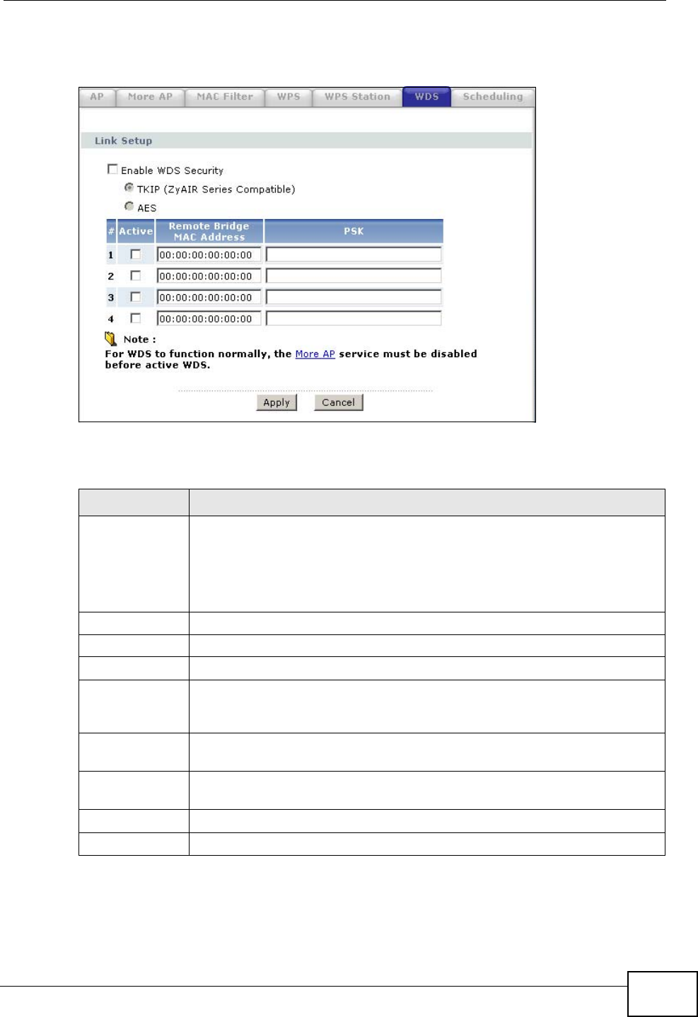
Click Network > Wireless LAN > WDS. The following screen displays.
Figure 101 Network > Wireless LAN > WDS
The following table describes the labels in this screen.
Table 37 Network > Wireless LAN > WDS
LABEL DESCRIPTION
Enable WDS
Security Select this option and the type of the key used to encrypt data between
APs. All the wireless APs (including the ZyXEL Device) must use the
same pre-shared key for data transmission.
If you de-select this option, the data sent between APs is not encrypted.
Anyone can read it.
TKIP Select this to use TKIP (Temporal Key Integrity Protocol) encryption.
AES Select this to use AES (Advanced Encryption Standard) encryption.
# This is the index number of the individual WDS link.
Active Select this to activate the link between the ZyXEL Device and the peer
device to which this entry refers. When you do not select the check box
this link is down.
Remote Bridge
MAC Address Type the MAC address of the peer device in a valid MAC address format
(six hexadecimal character pairs, for example 12:34:56:78:9a:bc).
PSK Enter a Pre-Shared Key (PSK) from 8 to 63 case-sensitive ASCII
characters (including spaces and symbols).
Apply Click Apply to save your changes back to the ZyXEL Device.
Cancel Click Cancel to reload the previous configuration for this screen.
Chapter 8 Wireless LAN
P-2612HWU-F1 User’s Guide
152
8.8 Scheduling Screen
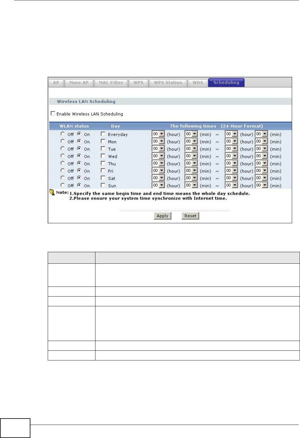
Click Network > Wireless LAN > Scheduling to open the Wireless LAN
Scheduling screen. Use this screen to configure when the ZyXEL Device enables
or disables the wireless LAN.
Figure 102 Network > Wireless LAN > Scheduling
The following table describes the labels in this screen.
Table 38 Network > Wireless LAN > Scheduling
LABEL DESCRIPTION
Enable
Wireless LAN
Scheduling
Select this to activate wireless LAN scheduling on your ZyXEL Device.
WLAN status Select On or Off to enable or disable the wireless LAN.
Day Select the day(s) you want to turn the wireless LAN on or off.
The following
times Specify the time period during which to apply the schedule.
For example, if you decide to turn off the wireless LAN everyday, but you
set an exception from 12:00 to 1:30. Then the wireless LAN is only
available from 12:00 to 1:30 everyday.
Apply Click this to save your changes.
Reset Click this to restore your previously saved settings.
Chapter 8 Wireless LAN
P-2612HWU-F1 User’s Guide 153
8.9 Wireless LAN Technical Reference
This section discusses wireless LANs in depth. For more information, see the
appendix.
8.9.1 Additional Wireless Terms
The following table describes some wireless network terms and acronyms used in
the ZyXEL Device’s Web Configurator.
8.9.2 Wireless Security Overview
The following sections introduce different types of wireless security you can set up
in the wireless network.
8.9.2.1 SSID
Normally, the ZyXEL Device acts like a beacon and regularly broadcasts the SSID
in the area. You can hide the SSID instead, in which case the ZyXEL Device does
not broadcast the SSID. In addition, you should change the default SSID to
something that is difficult to guess.
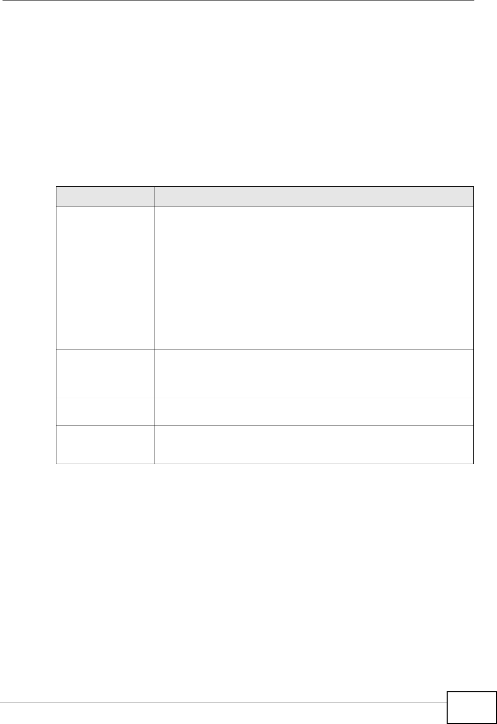
Table 39 Additional Wireless Terms
TERM DESCRIPTION
RTS/CTS Threshold In a wireless network which covers a large area, wireless devices
are sometimes not aware of each other’s presence. This may cause
them to send information to the AP at the same time and result in
information colliding and not getting through.
By setting this value lower than the default value, the wireless
devices must sometimes get permission to send information to the
ZyXEL Device. The lower the value, the more often the devices must
get permission.
If this value is greater than the fragmentation threshold value (see
below), then wireless devices never have to get permission to send
information to the ZyXEL Device.
Preamble A preamble affects the timing in your wireless network. There are
two preamble modes: long and short. If a device uses a different
preamble mode than the ZyXEL Device does, it cannot communicate
with the ZyXEL Device.
Authentication The process of verifying whether a wireless device is allowed to use
the wireless network.
Fragmentation
Threshold A small fragmentation threshold is recommended for busy networks,
while a larger threshold provides faster performance if the network
is not very busy.

Chapter 8 Wireless LAN
P-2612HWU-F1 User’s Guide
154
This type of security is fairly weak, however, because there are ways for
unauthorized wireless devices to get the SSID. In addition, unauthorized wireless
devices can still see the information that is sent in the wireless network.
8.9.2.2 MAC Address Filter
Every device that can use a wireless network has a unique identification number,
called a MAC address.1 A MAC address is usually written using twelve hexadecimal
characters2; for example, 00A0C5000002 or 00:A0:C5:00:00:02. To get the MAC
address for each device in the wireless network, see the device’s User’s Guide or
other documentation.
You can use the MAC address filter to tell the ZyXEL Device which devices are
allowed or not allowed to use the wireless network. If a device is allowed to use
the wireless network, it still has to have the correct information (SSID, channel,
and security). If a device is not allowed to use the wireless network, it does not
matter if it has the correct information.
This type of security does not protect the information that is sent in the wireless
network. Furthermore, there are ways for unauthorized wireless devices to get the
MAC address of an authorized device. Then, they can use that MAC address to use
the wireless network.
8.9.2.3 User Authentication
Authentication is the process of verifying whether a wireless device is allowed to
use the wireless network. You can make every user log in to the wireless network
before they can use it. However, every device in the wireless network has to
support IEEE 802.1x to do this.
For wireless networks, you can store the user names and passwords for each user
in a RADIUS server. This is a server used in businesses more than in homes. If you
do not have a RADIUS server, you cannot set up user names and passwords for
your users.
Unauthorized wireless devices can still see the information that is sent in the
wireless network, even if they cannot use the wireless network. Furthermore,
there are ways for unauthorized wireless users to get a valid user name and
password. Then, they can use that user name and password to use the wireless
network.
1. Some wireless devices, such as scanners, can detect wireless networks but cannot use wireless networks.
These kinds of wireless devices might not have MAC addresses.
2. Hexadecimal characters are 0, 1, 2, 3, 4, 5, 6, 7, 8, 9, A, B, C, D, E, and F.
Chapter 8 Wireless LAN
P-2612HWU-F1 User’s Guide 155
8.9.2.4 Encryption
Wireless networks can use encryption to protect the information that is sent in the
wireless network. Encryption is like a secret code. If you do not know the secret
code, you cannot understand the message.
The types of encryption you can choose depend on the type of authentication.
(See Section 8.9.2.3 on page 154 for information about this.)
For example, if the wireless network has a RADIUS server, you can choose WPA
or WPA2. If users do not log in to the wireless network, you can choose no
encryption, Static WEP, WPA-PSK, or WPA2-PSK.
Usually, you should set up the strongest encryption that every device in the
wireless network supports. For example, suppose you have a wireless network
with the ZyXEL Device and you do not have a RADIUS server. Therefore, there is
no authentication. Suppose the wireless network has two devices. Device A only
supports WEP, and device B supports WEP and WPA. Therefore, you should set up
Static WEP in the wireless network.
Note: It is recommended that wireless networks use WPA-PSK, WPA, or stronger
encryption. The other types of encryption are better than none at all, but it is still
possible for unauthorized wireless devices to figure out the original information
pretty quickly.
When you select WPA2 or WPA2-PSK in your ZyXEL Device, you can also select
an option (WPA compatible) to support WPA as well. In this case, if some of the
devices support WPA and some support WPA2, you should set up WPA2-PSK or
WPA2 (depending on the type of wireless network login) and select the WPA
compatible option in the ZyXEL Device.
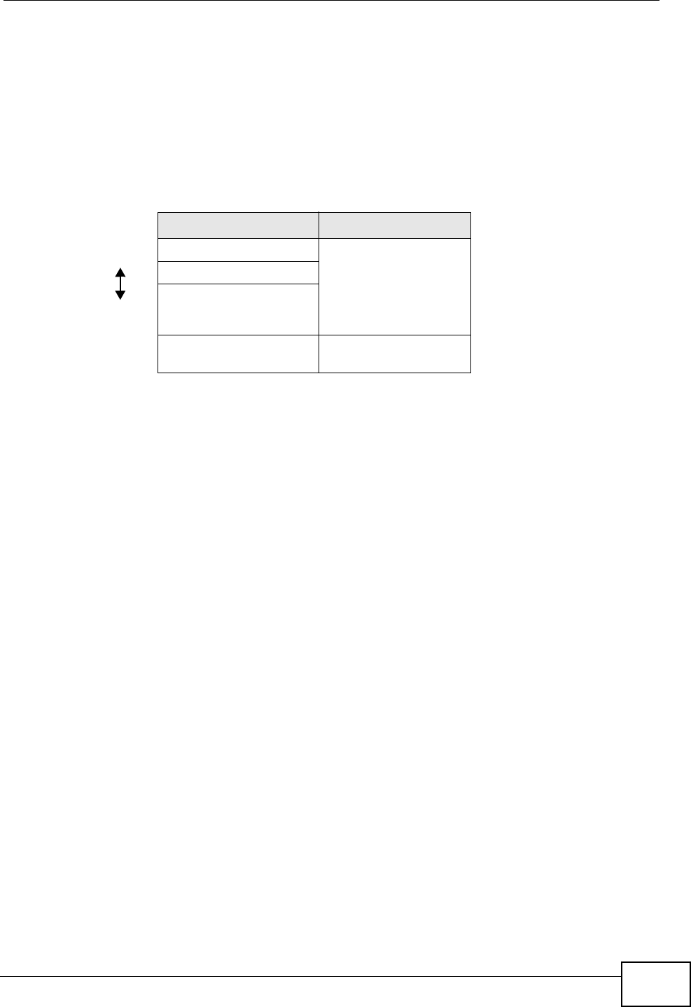
Many types of encryption use a key to protect the information in the wireless
network. The longer the key, the stronger the encryption. Every device in the
wireless network must have the same key.
Table 40 Types of Encryption for Each Type of Authentication
NO AUTHENTICATION RADIUS SERVER
Weakest No Security
WPA
Static WEP
WPA-PSK
Stronges
tWPA2-PSK WPA2
Chapter 8 Wireless LAN
P-2612HWU-F1 User’s Guide
156
8.9.3 MBSSID
Traditionally, you needed to use different APs to configure different Basic Service
Sets (BSSs). As well as the cost of buying extra APs, there was also the possibility
of channel interference. The ZyXEL Device’s MBSSID (Multiple Basic Service Set
IDentifier) function allows you to use one access point to provide several BSSs
simultaneously. You can then assign varying QoS priorities and/or security modes
to different SSIDs.
Wireless devices can use different BSSIDs to associate with the same AP.
8.9.3.1 Notes on Multiple BSSs
• A maximum of eight BSSs are allowed on one AP simultaneously.
• You must use different keys for different BSSs. If two wireless devices have
different BSSIDs (they are in different BSSs), but have the same keys, they
may hear each other’s communications (but not communicate with each other).
• MBSSID should not replace but rather be used in conjunction with 802.1x
security.
8.9.4 Wireless Distribution System (WDS)
The ZyXEL Device can act as a wireless network bridge and establish WDS
(Wireless Distribution System) links with other APs. You need to know the MAC
addresses of the APs you want to link to. Once the security settings of peer sides
match one another, the connection between devices is made.
At the time of writing, WDS security is compatible with other ZyXEL access points
only. Refer to your other access point’s documentation for details.
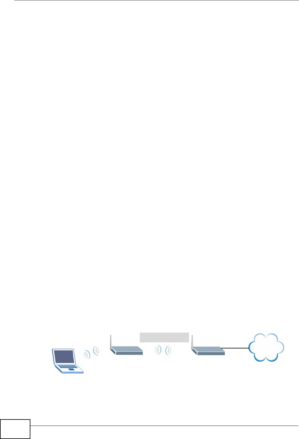
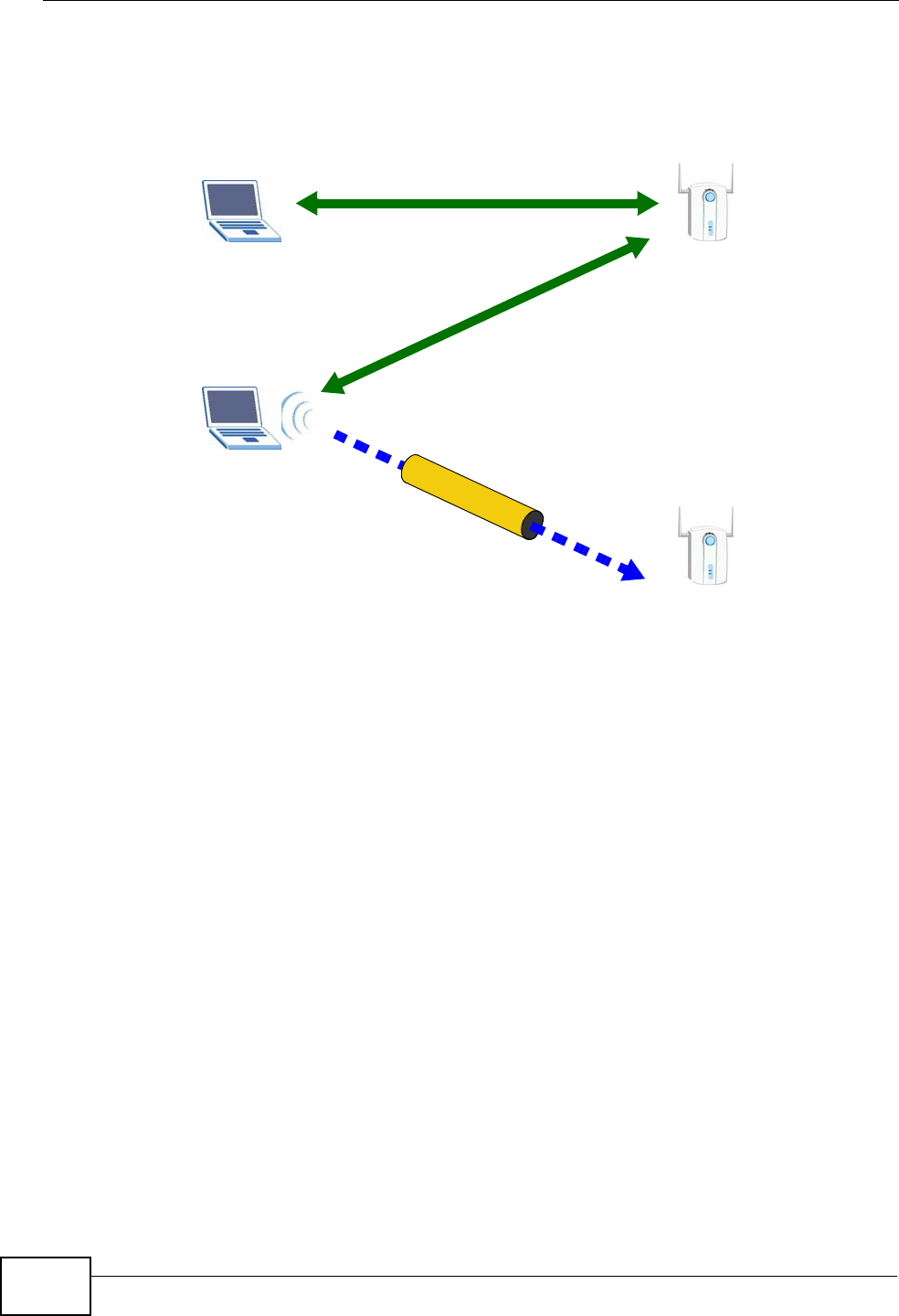
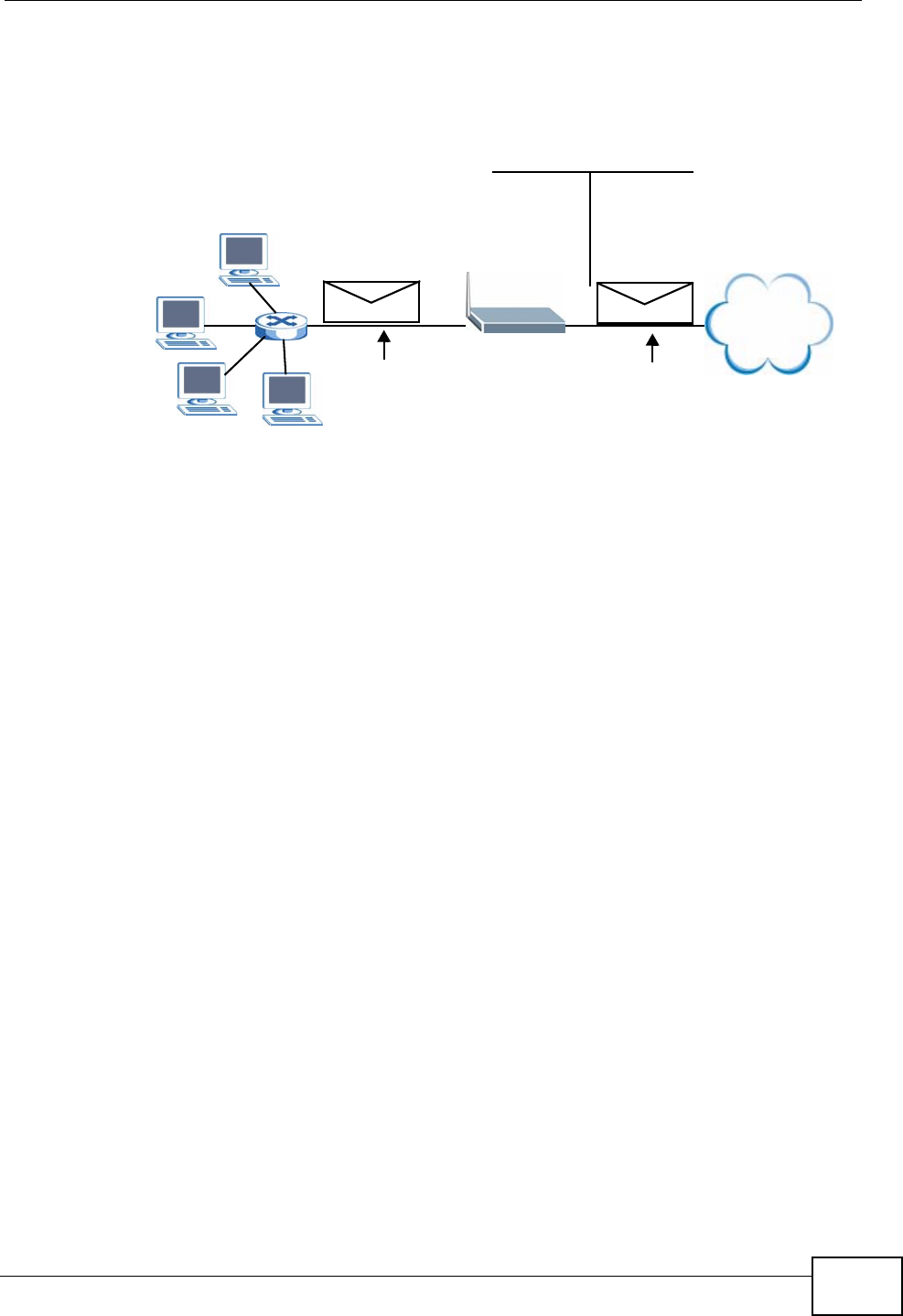
The following example illustrates how WDS link works between APs. Notebook
computer A is a wireless client connecting to access point AP 1. AP 1 has no
wired Internet connection, but can establish a WDS link with access point AP 2,
which does. When AP 1 has a WDS link with AP 2, the notebook computer can
access the Internet through AP 2.
Figure 103 WDS Link Example
WDS
AP 2
AP 1
Internet
A

Chapter 8 Wireless LAN
P-2612HWU-F1 User’s Guide 157
8.9.5 WiFi Protected Setup
Your ZyXEL Device supports WiFi Protected Setup (WPS), which is an easy way to
set up a secure wireless network. WPS is an industry standard specification,
defined by the WiFi Alliance.
WPS allows you to quickly set up a wireless network with strong security, without
having to configure security settings manually. Each WPS connection works
between two devices. Both devices must support WPS (check each device’s
documentation to make sure).
Depending on the devices you have, you can either press a button (on the device
itself, or in its configuration utility) or enter a PIN (a unique Personal Identification
Number that allows one device to authenticate the other) in each of the two
devices. When WPS is activated on a device, it has two minutes to find another
device that also has WPS activated. Then, the two devices connect and set up a
secure network by themselves.
8.9.5.1 Push Button Configuration
WPS Push Button Configuration (PBC) is initiated by pressing a button on each
WPS-enabled device, and allowing them to connect automatically. You do not need
to enter any information.
Not every WPS-enabled device has a physical WPS button. Some may have a WPS
PBC button in their configuration utilities instead of or in addition to the physical
button.
Take the following steps to set up WPS using the button.
1Ensure that the two devices you want to set up are within wireless range of one
another.
2Look for a WPS button on each device. If the device does not have one, log into its
configuration utility and locate the button (see the device’s User’s Guide for how to
do this - for the ZyXEL Device, see Section 8.6 on page 149).
3Press the button on one of the devices (it doesn’t matter which). For the ZyXEL
Device you must press the WPS button for more than three seconds.
4Within two minutes, press the button on the other device. The registrar sends the
network name (SSID) and security key through an secure connection to the
enrollee.
If you need to make sure that WPS worked, check the list of associated wireless
clients in the AP’s configuration utility. If you see the wireless client in the list,
WPS was successful.

Chapter 8 Wireless LAN
P-2612HWU-F1 User’s Guide
158
8.9.5.2 PIN Configuration
Each WPS-enabled device has its own PIN (Personal Identification Number). This
may either be static (it cannot be changed) or dynamic (in some devices you can
generate a new PIN by clicking on a button in the configuration interface).
Use the PIN method instead of the push-button configuration (PBC) method if you
want to ensure that the connection is established between the devices you specify,
not just the first two devices to activate WPS in range of each other. However, you
need to log into the configuration interfaces of both devices to use the PIN
method.
When you use the PIN method, you must enter the PIN from one device (usually
the wireless client) into the second device (usually the Access Point or wireless
router). Then, when WPS is activated on the first device, it presents its PIN to the
second device. If the PIN matches, one device sends the network and security
information to the other, allowing it to join the network.
Take the following steps to set up a WPS connection between an access point or
wireless router (referred to here as the AP) and a client device using the PIN
method.
1Ensure WPS is enabled on both devices.
2Access the WPS section of the AP’s configuration interface. See the device’s User’s
Guide for how to do this.
3Look for the client’s WPS PIN; it will be displayed either on the device, or in the
WPS section of the client’s configuration interface (see the device’s User’s Guide
for how to find the WPS PIN - for the ZyXEL Device, see Section 8.5 on page 148).
4Enter the client’s PIN in the AP’s configuration interface.
Note: If the client device’s configuration interface has an area for entering another
device’s PIN, you can either enter the client’s PIN in the AP, or enter the AP’s
PIN in the client - it does not matter which.
5Start WPS on both devices within two minutes.
Note: Use the configuration utility to activate WPS, not the push-button on the device
itself.
6On a computer connected to the wireless client, try to connect to the Internet. If
you can connect, WPS was successful.
If you cannot connect, check the list of associated wireless clients in the AP’s
configuration utility. If you see the wireless client in the list, WPS was successful.
Chapter 8 Wireless LAN
P-2612HWU-F1 User’s Guide 159
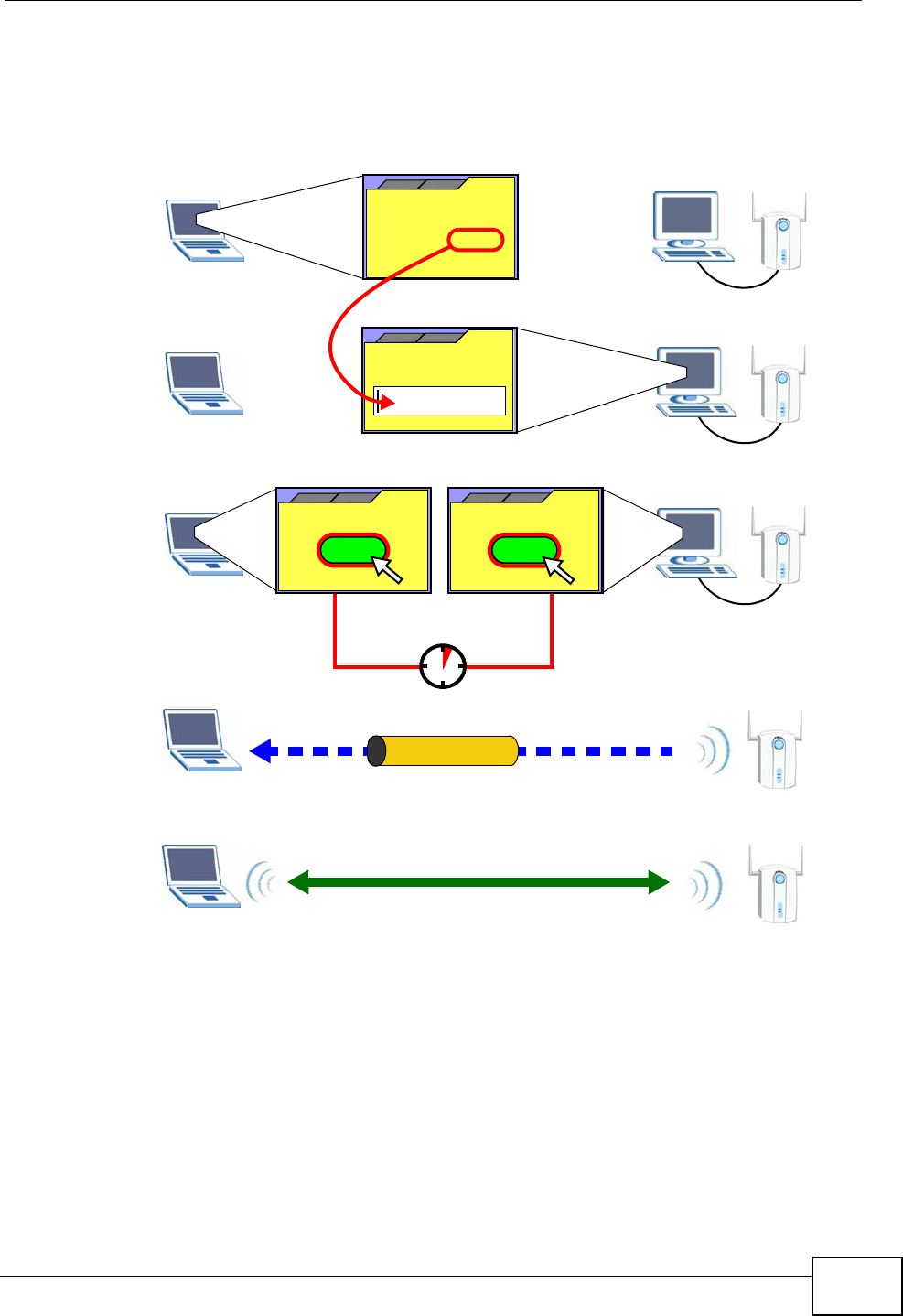
The following figure shows a WPS-enabled wireless client (installed in a notebook
computer) connecting to the WPS-enabled AP via the PIN method.
Figure 104 Example WPS Process: PIN Method
8.9.5.3 How WPS Works
When two WPS-enabled devices connect, each device must assume a specific role.
One device acts as the registrar (the device that supplies network and security
settings) and the other device acts as the enrollee (the device that receives
network and security settings. The registrar creates a secure EAP (Extensible
Authentication Protocol) tunnel and sends the network name (SSID) and the WPA-
PSK or WPA2-PSK pre-shared key to the enrollee. Whether WPA-PSK or WPA2-PSK
is used depends on the standards supported by the devices. If the registrar is
already part of a network, it sends the existing information. If not, it generates
the SSID and WPA(2)-PSK randomly.
ENROLLEE
SECURE EAP TUNNEL
SSID
WPA(2)-PSK
WITHIN 2 MINUTES
COMMUNICATION
This device’s
WPS
Enter WPS PIN
WPS
from other device:
WPS PIN: 123456
WPS
START
WPS
START
REGISTRAR
Chapter 8 Wireless LAN
P-2612HWU-F1 User’s Guide
160
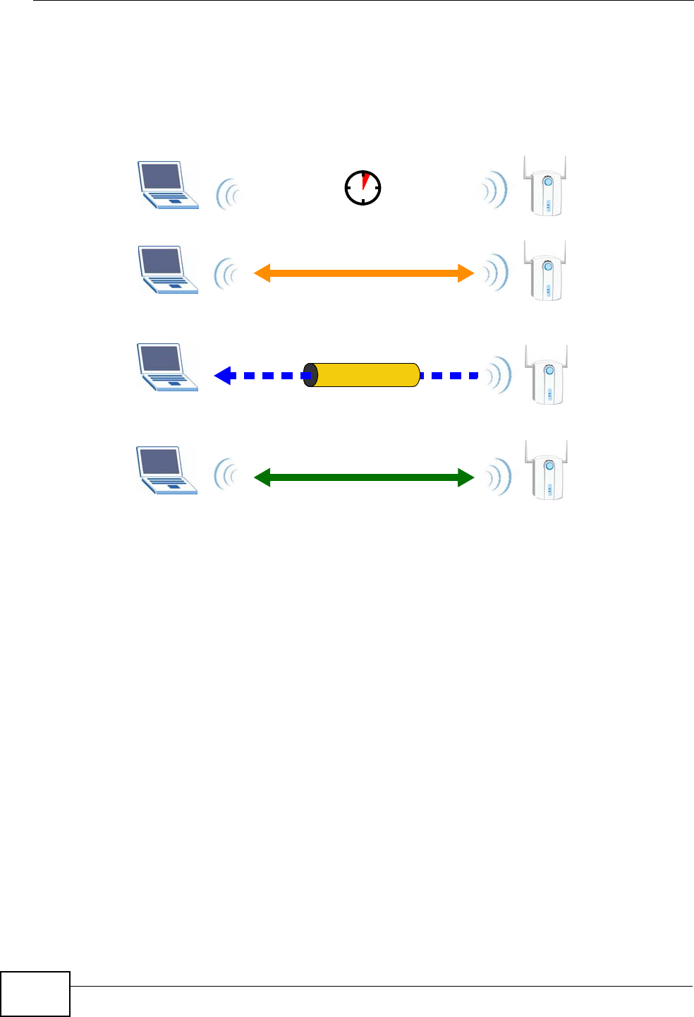
The following figure shows a WPS-enabled client (installed in a notebook
computer) connecting to a WPS-enabled access point.
Figure 105 How WPS works
The roles of registrar and enrollee last only as long as the WPS setup process is
active (two minutes). The next time you use WPS, a different device can be the
registrar if necessary.
The WPS connection process is like a handshake; only two devices participate in
each WPS transaction. If you want to add more devices you should repeat the
process with one of the existing networked devices and the new device.
Note that the access point (AP) is not always the registrar, and the wireless client
is not always the enrollee. All WPS-certified APs can be a registrar, and so can
some WPS-enabled wireless clients.
By default, a WPS devices is “unconfigured”. This means that it is not part of an
existing network and can act as either enrollee or registrar (if it supports both
functions). If the registrar is unconfigured, the security settings it transmits to the
enrollee are randomly-generated. Once a WPS-enabled device has connected to
another device using WPS, it becomes “configured”. A configured wireless client
can still act as enrollee or registrar in subsequent WPS connections, but a
configured access point can no longer act as enrollee. It will be the registrar in all
subsequent WPS connections in which it is involved. If you want a configured AP to
act as an enrollee, you must reset it to its factory defaults.
SECURE TUNNEL
SECURITY INFO
WITHIN 2 MINUTES
COMMUNICATION
ACTIVATE
WPS
ACTIVATE
WPS
WPS HANDSHAKE
REGISTRARENROLLEE
Chapter 8 Wireless LAN
P-2612HWU-F1 User’s Guide 161
8.9.5.4 Example WPS Network Setup
This section shows how security settings are distributed in an example WPS setup.
The following figure shows an example network. In step 1, both AP1 and Client 1
are unconfigured. When WPS is activated on both, they perform the handshake. In
this example, AP1 is the registrar, and Client 1 is the enrollee. The registrar
randomly generates the security information to set up the network, since it is
unconfigured and has no existing information.
Figure 106 WPS: Example Network Step 1
In step 2, you add another wireless client to the network. You know that Client 1
supports registrar mode, but it is better to use AP1 for the WPS handshake with
the new client since you must connect to the access point anyway in order to use
the network. In this case, AP1 must be the registrar, since it is configured (it
already has security information for the network). AP1 supplies the existing
security information to Client 2.
Figure 107 WPS: Example Network Step 2
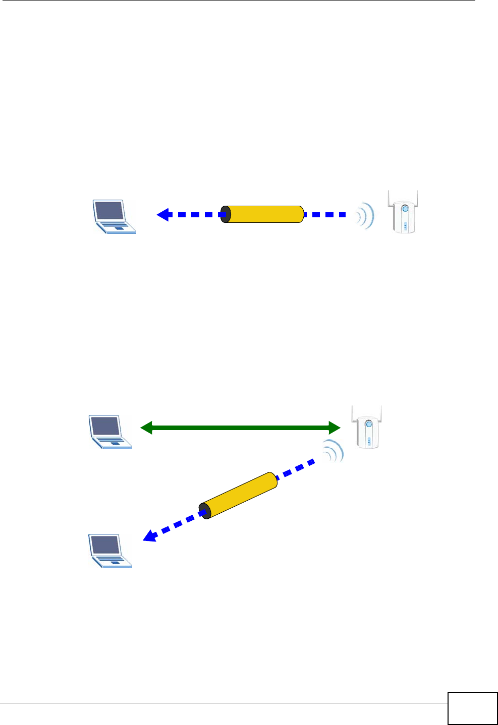
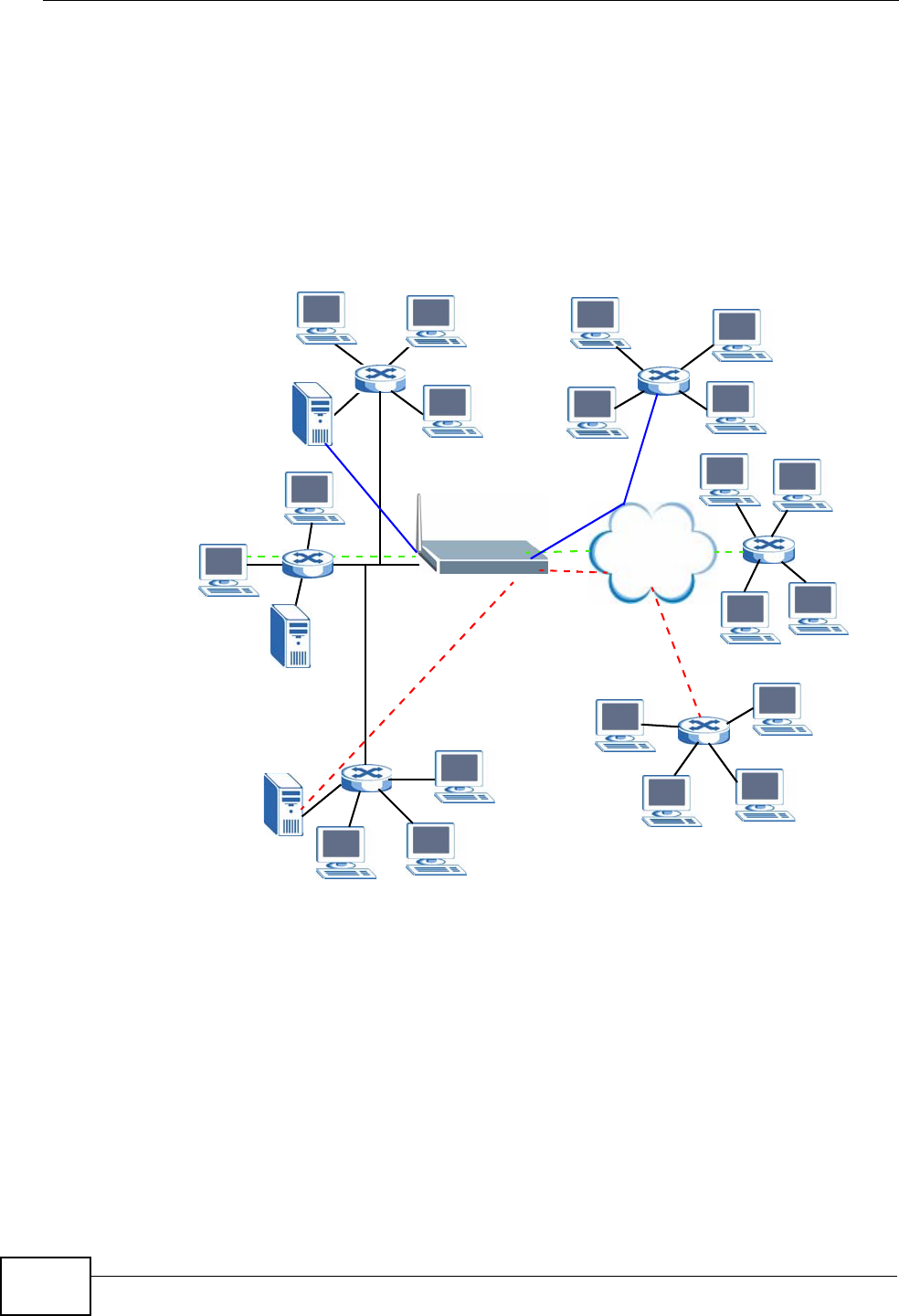
In step 3, you add another access point (AP2) to your network. AP2 is out of
range of AP1, so you cannot use AP1 for the WPS handshake with the new access
REGISTRARENROLLEE
SECURITY INFO
CLIENT 1 AP1
REGISTRAR
CLIENT 1 AP1
ENROLLEE
CLIENT 2
EXISTING CONNECTION
SECURITY INFO
Chapter 8 Wireless LAN
P-2612HWU-F1 User’s Guide
162
point. However, you know that Client 2 supports the registrar function, so you use
it to perform the WPS handshake instead.
Figure 108 WPS: Example Network Step 3
8.9.5.5 Limitations of WPS
WPS has some limitations of which you should be aware.
• WPS works in Infrastructure networks only (where an AP and a wireless client
communicate). It does not work in Ad-Hoc networks (where there is no AP).
• When you use WPS, it works between two devices only. You cannot enroll
multiple devices simultaneously, you must enroll one after the other.
For instance, if you have two enrollees and one registrar you must set up the
first enrollee (by pressing the WPS button on the registrar and the first enrollee,
for example), then check that it successfully enrolled, then set up the second
device in the same way.
• WPS works only with other WPS-enabled devices. However, you can still add
non-WPS devices to a network you already set up using WPS.
WPS works by automatically issuing a randomly-generated WPA-PSK or WPA2-
PSK pre-shared key from the registrar device to the enrollee devices. Whether
the network uses WPA-PSK or WPA2-PSK depends on the device. You can check
the configuration interface of the registrar device to discover the key the
network is using (if the device supports this feature). Then, you can enter the
key into the non-WPS device and join the network as normal (the non-WPS
device must also support WPA-PSK or WPA2-PSK).
CLIENT 1 AP1
REGISTRAR
CLIENT 2
EXISTING CONNECTION
SECURITY INFO
ENROLLEE
AP2
EXISTING CONNECTION

Chapter 8 Wireless LAN
P-2612HWU-F1 User’s Guide 163
• When you use the PBC method, there is a short period (from the moment you
press the button on one device to the moment you press the button on the
other device) when any WPS-enabled device could join the network. This is
because the registrar has no way of identifying the “correct” enrollee, and
cannot differentiate between your enrollee and a rogue device. This is a possible
way for a hacker to gain access to a network.
You can easily check to see if this has happened. WPS works between only two
devices simultaneously, so if another device has enrolled your device will be
unable to enroll, and will not have access to the network. If this happens, open
the access point’s configuration interface and look at the list of associated
clients (usually displayed by MAC address). It does not matter if the access
point is the WPS registrar, the enrollee, or was not involved in the WPS
handshake; a rogue device must still associate with the access point to gain
access to the network. Check the MAC addresses of your wireless clients
(usually printed on a label on the bottom of the device). If there is an unknown
MAC address you can remove it or reset the AP.

Chapter 8 Wireless LAN
P-2612HWU-F1 User’s Guide
164

P-2612HWU-F1 User’s Guide 165
CHAPTER 9
Network Address Translation
(NAT)
9.1 Overview
NAT (Network Address Translation - NAT, RFC 1631) is the translation of the IP
address of a host in a packet, for example, the source address of an outgoing
packet, used within one network to a different IP address known within another
network.
9.1.1 What You Can Do in the NAT Screens
•Use the NAT General Setup screen (Section 9.2 on page 166) to configure the
NAT setup settings.
•Use the Port Forwarding screen (Section 9.3 on page 168) to configure
forward incoming service requests to the server(s) on your local network.
•Use the Address Mapping screen (Section 9.4 on page 172) to change your
ZyXEL Device’s address mapping settings.
•Use the SIP ALG screen (Section 9.4.2 on page 174) to enable and disable the
SIP (VoIP) ALG in the ZyXEL Device.
9.1.2 What You Need To Know About NAT
Inside/Outside and Global/Local
Inside/outside denotes where a host is located relative to the ZyXEL Device, for
example, the computers of your subscribers are the inside hosts, while the web
servers on the Internet are the outside hosts.
Global/local denotes the IP address of a host in a packet as the packet traverses a
router, for example, the local address refers to the IP address of a host when the
packet is in the local network, while the global address refers to the IP address of
the host when the same packet is traveling in the WAN side.

Chapter 9 Network Address Translation (NAT)
P-2612HWU-F1 User’s Guide
166
NAT
In the simplest form, NAT changes the source IP address in a packet received from
a subscriber (the inside local address) to another (the inside global address)
before forwarding the packet to the WAN side. When the response comes back,
NAT translates the destination address (the inside global address) back to the
inside local address before forwarding it to the original inside host.
Port Forwarding
A port forwarding set is a list of inside (behind NAT on the LAN) servers, for
example, web or FTP, that you can make visible to the outside world even though
NAT makes your whole inside network appear as a single computer to the outside
world.
SUA (Single User Account) Versus NAT
SUA (Single User Account) is a ZyNOS implementation of a subset of NAT that
supports two types of mapping, Many-to-One and Server. The ZyXEL Device also
supports Full Feature NAT to map multiple global IP addresses to multiple private
LAN IP addresses of clients or servers using mapping types as outlined in Table 48
on page 179.
• Choose SUA Only if you have just one public WAN IP address for your ZyXEL
Device.
• Choose Full Feature if you have multiple public WAN IP addresses for your
ZyXEL Device.
Finding Out More
See Section 9.5 on page 175 for advanced technical information on NAT.
9.2 NAT General Setup
Note: You must create a firewall rule in addition to setting up SUA/NAT, to allow traffic
from the WAN to be forwarded through the ZyXEL Device.
Chapter 9 Network Address Translation (NAT)
P-2612HWU-F1 User’s Guide 167
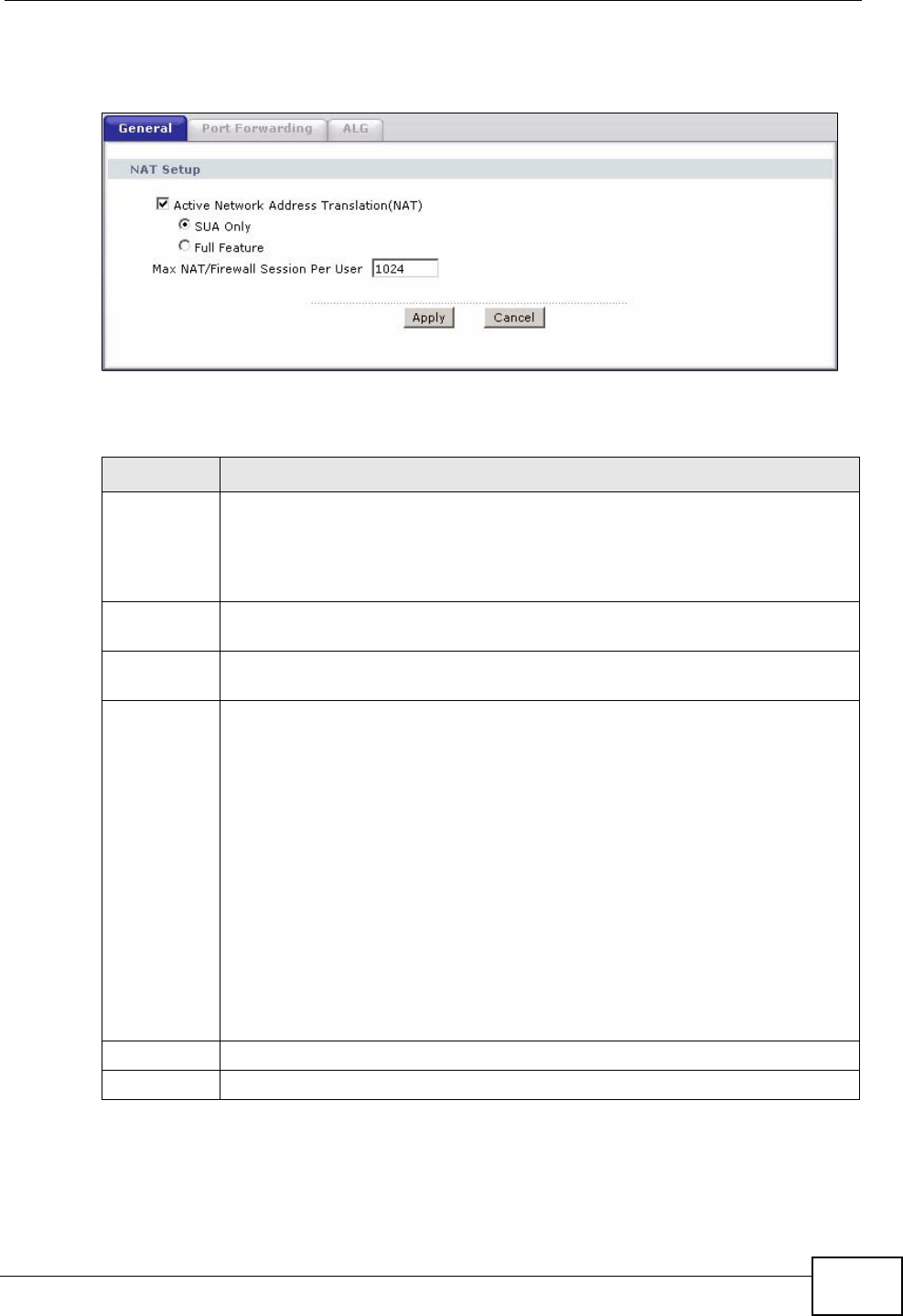
Click Network > NAT to open the following screen.
Figure 109 Network > NAT > General
The following table describes the labels in this screen.
Table 41 Network > NAT > General
LABEL DESCRIPTION
Active
Network
Address
Translation
(NAT)
Select this check box to enable NAT.
SUA Only Select this radio button if you have just one public WAN IP address for your
ZyXEL Device.
Full Feature Select this radio button if you have multiple public WAN IP addresses for
your ZyXEL Device.
Max NAT/
Firewall
Session Per
User
When computers use peer to peer applications, such as file sharing
applications, they need to establish NAT sessions. If you do not limit the
number of NAT sessions a single client can establish, this can result in all of
the available NAT sessions being used. In this case, no additional NAT
sessions can be established, and users may not be able to access the
Internet.
Each NAT session establishes a corresponding firewall session. Use this field
to limit the number of NAT/Firewall sessions client computers can establish
through the ZyXEL Device.
If your network has a small number of clients using peer to peer
applications, you can raise this number to ensure that their performance is
not degraded by the number of NAT sessions they can establish. If your
network has a large number of users using peer to peer applications, you
can lower this number to ensure no single client is exhausting all of the
available NAT sessions.
Apply Click Apply to save your changes back to the ZyXEL Device.
Cancel Click Cancel to reload the previous configuration for this screen.

Chapter 9 Network Address Translation (NAT)
P-2612HWU-F1 User’s Guide
168
9.3 Port Forwarding
Note: This screen is available only when you select SUA only in the NAT > General
screen.
Use the Port Forwarding screen to forward incoming service requests to the
server(s) on your local network.
You may enter a single port number or a range of port numbers to be forwarded,
and the local IP address of the desired server. The port number identifies a
service; for example, web service is on port 80 and FTP on port 21. In some
cases, such as for unknown services or where one server can support more than
one service (for example both FTP and web service), it might be better to specify
a range of port numbers. You can allocate a server IP address that corresponds to
a port or a range of ports.
The most often used port numbers and services are shown in Appendix E on page
557. Please refer to RFC 1700 for further information about port numbers.
Note: Many residential broadband ISP accounts do not allow you to run any server
processes (such as a Web or FTP server) from your location. Your ISP may
periodically check for servers and may suspend your account if it discovers any
active services at your location. If you are unsure, refer to your ISP.
Default Server IP Address
In addition to the servers for specified services, NAT supports a default server IP
address. A default server receives packets from ports that are not specified in this
screen.
Note: If you do not assign a Default Server IP address, the ZyXEL Device discards
all packets received for ports that are not specified here or in the remote
management setup.
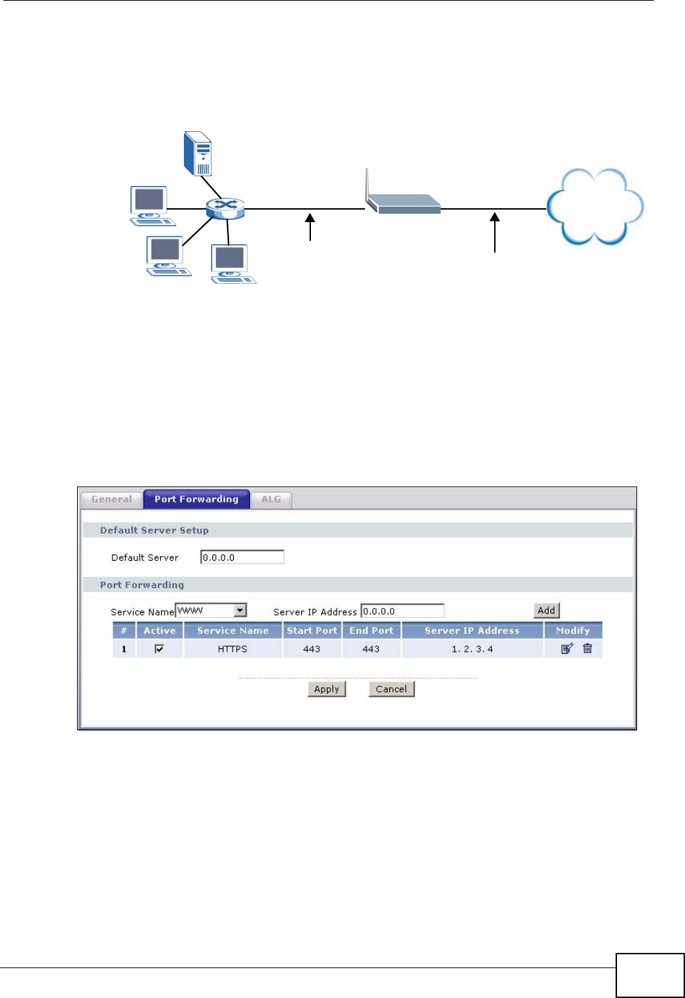
Configuring Servers Behind Port Forwarding (Example)
Let's say you want to assign ports 21-25 to one FTP, Telnet and SMTP server (A in
the example), port 80 to another (B in the example) and assign a default server IP
address of 192.168.1.35 to a third (C in the example). You assign the LAN IP
Chapter 9 Network Address Translation (NAT)
P-2612HWU-F1 User’s Guide 169
addresses and the ISP assigns the WAN IP address. The NAT network appears as a
single host on the Internet.
Figure 110 Multiple Servers Behind NAT Example
9.3.1 Configuring the Port Forwarding Screen
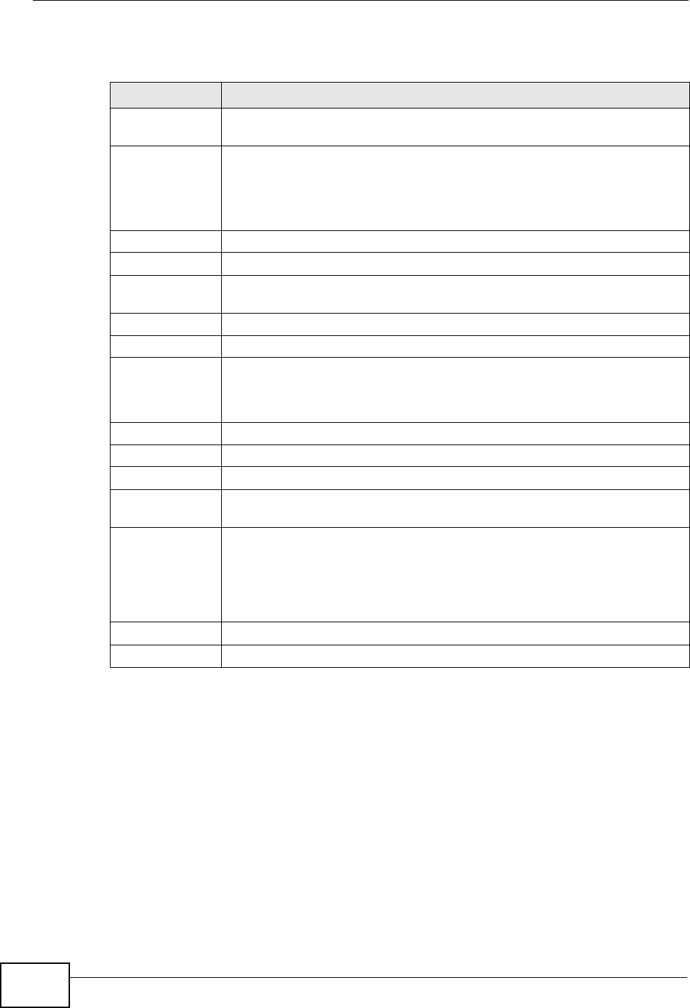
Click Network > NAT > Port Forwarding to open the following screen.
See Appendix E on page 557 for port numbers commonly used for particular
services.
Figure 111 Network > NAT > Port Forwarding
A=192.168.1.33
D=192.168.1.36
C=192.168.1.35
B=192.168.1.34
Internet
WAN
LAN
192.168.1.1 IP Address assigned by ISP
Chapter 9 Network Address Translation (NAT)
P-2612HWU-F1 User’s Guide
170
The following table describes the fields in this screen.
Table 42 Network > NAT > Port Forwarding
LABEL DESCRIPTION
Default Server
Setup
Default Server In addition to the servers for specified services, NAT supports a default
server. A default server receives packets from ports that are not
specified in this screen. If you do not assign a Default Server IP
address, the ZyXEL Device discards all packets received for ports that
are not specified here or in the remote management setup.
Port Forwarding
Service Name Select a service from the drop-down list box.
Server IP
Address Enter the IP address of the server for the specified service.
Add Click this button to add a rule to the table below.
#This is the rule index number (read-only).
Active This field indicates whether the rule is active or not.
Clear the check box to disable the rule. Select the check box to enable
it.
Service Name This is a service’s name.
Start Port This is the first port number that identifies a service.
End Port This is the last port number that identifies a service.
Server IP
Address This is the server’s IP address.
Modify Click the edit icon to go to the screen where you can edit the port
forwarding rule.
Click the delete icon to delete an existing port forwarding rule. Note that
subsequent address mapping rules move up by one when you take this
action.
Apply Click Apply to save your changes back to the ZyXEL Device.
Cancel Click Cancel to return to the previous configuration.
Chapter 9 Network Address Translation (NAT)
P-2612HWU-F1 User’s Guide 171
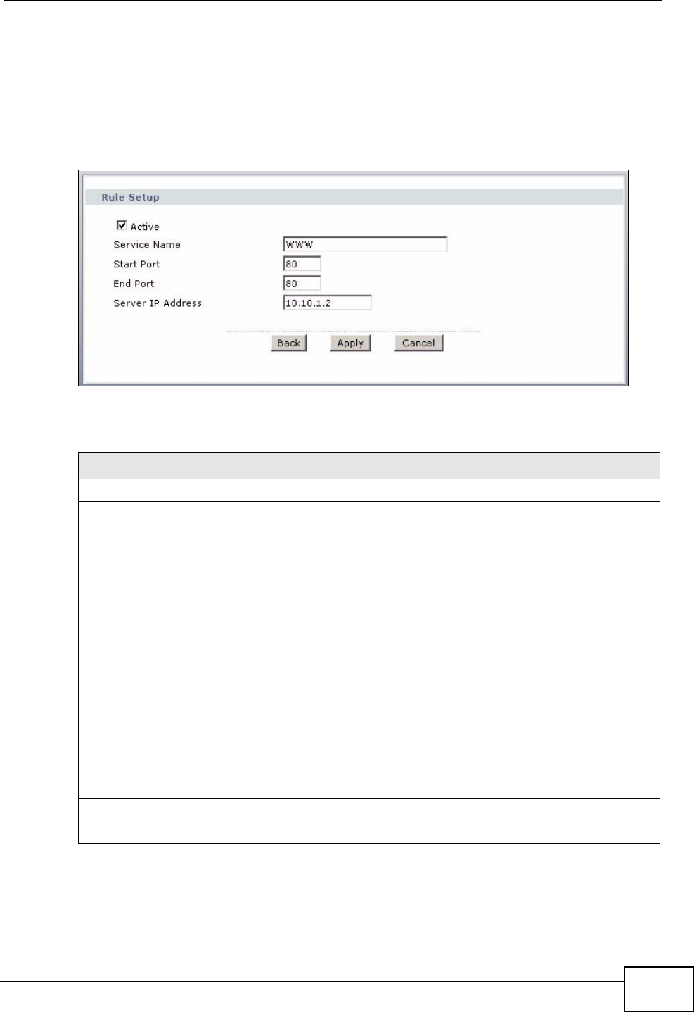
9.3.2 Port Forwarding Rule Edit
Use this screen to add or edit a port forwarding rule. Select User define in the
Service Name field of the Port Forwarding screen or click an existing rule’s edit
icon in the Port Forwarding screen to display the screen shown next.
Figure 112 Network > NAT > Port Forwarding > Edit
The following table describes the fields in this screen.
Table 43 Network > NAT > Port Forwarding > Edit
LABEL DESCRIPTION
Active Click this check box to enable the rule.
Service Name Enter a name to identify this port-forwarding rule.
Start Port Enter a port number in this field.
To forward only one port, enter the port number again in the End Port
field.
To forward a series of ports, enter the start port number here and the end
port number in the End Port field.
End Port Enter a port number in this field.
To forward only one port, enter the port number again in the Start Port
field above and then enter it again in this field.
To forward a series of ports, enter the last port number in a series that
begins with the port number in the Start Port field above.
Server IP
Address Enter the inside IP address of the server here.
Back Click Back to return to the previous screen.
Apply Click Apply to save your changes back to the ZyXEL Device.
Cancel Click Cancel to begin configuring this screen afresh.
Chapter 9 Network Address Translation (NAT)
P-2612HWU-F1 User’s Guide
172
9.4 Address Mapping
Note: The Address Mapping screen is available only when you select Full Feature
in the NAT > General screen.
Ordering your rules is important because the ZyXEL Device applies the rules in the
order that you specify. When a rule matches the current packet, the ZyXEL Device
takes the corresponding action and the remaining rules are ignored. If there are
any empty rules before your new configured rule, your configured rule will be
pushed up by that number of empty rules. For example, if you have already
configured rules 1 to 6 in your current set and now you configure rule number 9.
In the set summary screen, the new rule will be rule 7, not 9. Now if you delete
rule 4, rules 5 to 7 will be pushed up by 1 rule, so old rules 5, 6 and 7 become new
rules 4, 5 and 6.
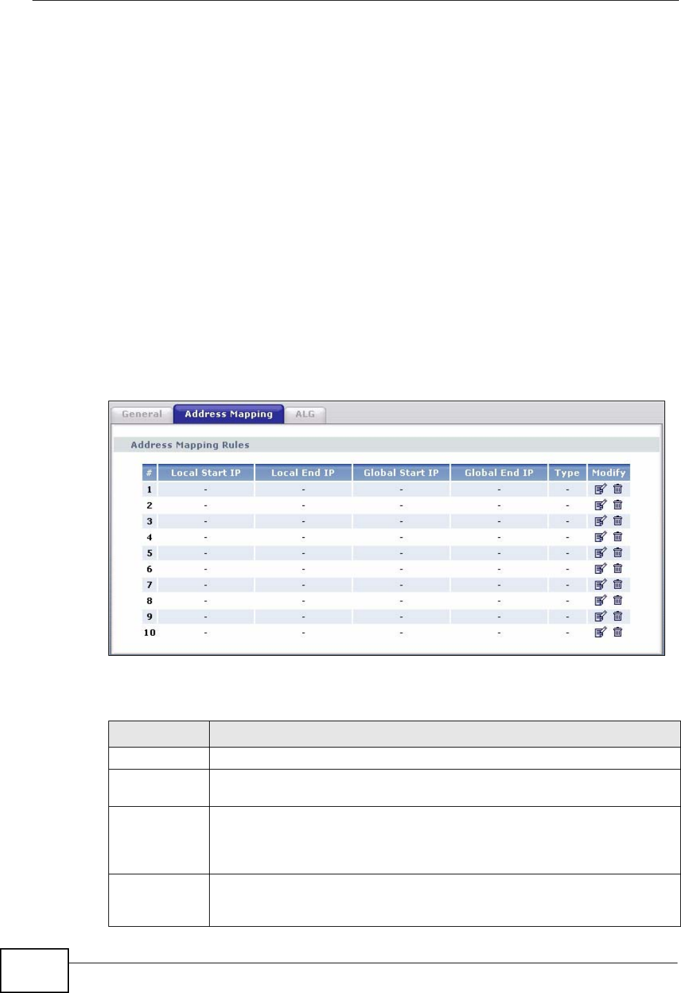
To change your ZyXEL Device’s address mapping settings, click Network > NAT
> Address Mapping to open the following screen.
Figure 113 Network > NAT > Address Mapping
The following table describes the fields in this screen.
Table 44 Network > NAT > Address Mapping
LABEL DESCRIPTION
#This is the rule index number.
Local Start IP This is the starting Inside Local IP Address (ILA). Local IP addresses are
N/A for Server port mapping.
Local End IP This is the end Inside Local IP Address (ILA). If the rule is for all local IP
addresses, then this field displays 0.0.0.0 as the Local Start IP address
and 255.255.255.255 as the Local End IP address. This field is N/A for
One-to-one and Server mapping types.
Global Start
IP This is the starting Inside Global IP Address (IGA). Enter 0.0.0.0 here if
you have a dynamic IP address from your ISP. You can only do this for
Many-to-One and Server mapping types.
Chapter 9 Network Address Translation (NAT)
P-2612HWU-F1 User’s Guide 173
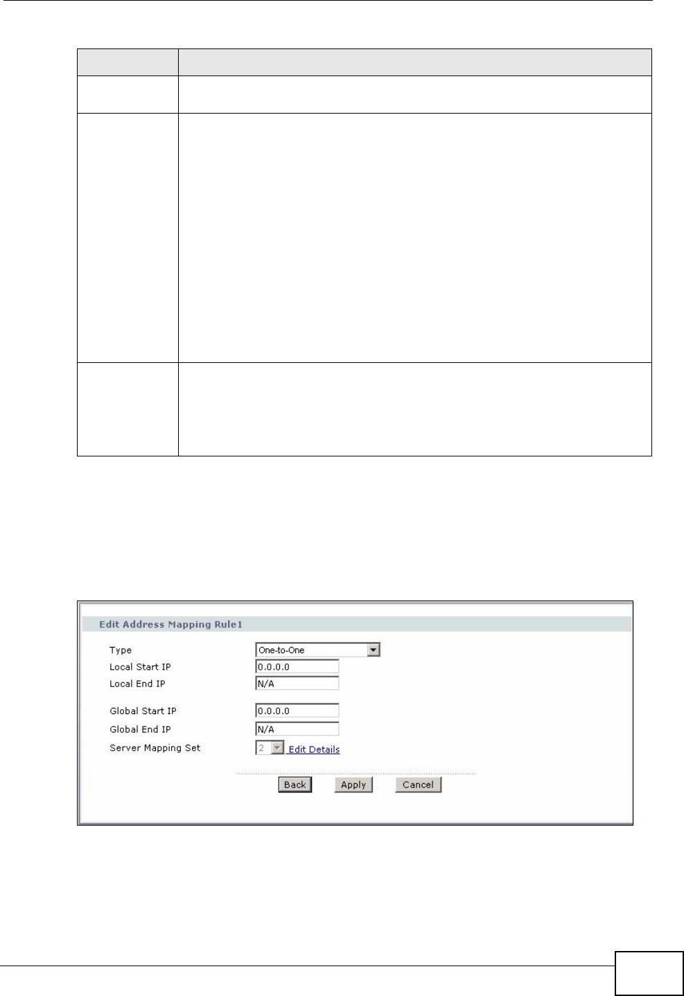
9.4.1 Address Mapping Rule Edit
To edit an address mapping rule, click the rule’s edit icon in the Address
Mapping screen to display the screen shown next.
Figure 114 Network > NAT > Address Mapping > Edit
Global End IP This is the ending Inside Global IP Address (IGA). This field is N/A for
One-to-one, Many-to-One and Server mapping types.
Type 1-1: One-to-one mode maps one local IP address to one global IP
address. Note that port numbers do not change for the One-to-one NAT
mapping type.
M-1: Many-to-One mode maps multiple local IP addresses to one global
IP address. This is equivalent to SUA (i.e., PAT, port address translation),
ZyXEL's Single User Account feature that previous ZyXEL routers
supported only.
M-M Ov (Overload): Many-to-Many Overload mode maps multiple local
IP addresses to shared global IP addresses.
MM No (No Overload): Many-to-Many No Overload mode maps each local
IP address to unique global IP addresses.
Server: This type allows you to specify inside servers of different
services behind the NAT to be accessible to the outside world.
Modify Click the edit icon to go to the screen where you can edit the address
mapping rule.
Click the delete icon to delete an existing address mapping rule. Note that
subsequent address mapping rules move up by one when you take this
action.
Table 44 Network > NAT > Address Mapping (continued)
LABEL DESCRIPTION
Chapter 9 Network Address Translation (NAT)
P-2612HWU-F1 User’s Guide
174
The following table describes the fields in this screen.
9.4.2 SIP ALG
A SIP Application Layer Gateway (ALG) allows SIP calls to pass through NAT by
examining and translating IP addresses embedded in the data stream. When the
ZyXEL Device registers with the SIP register server, the SIP ALG translates the
ZyXEL Device’s private IP address inside the SIP data stream to a public IP
address. You do not need to use STUN or an outbound proxy if your ZyXEL Device
is behind a SIP ALG.
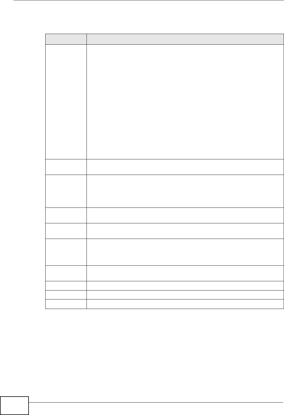
Table 45 Network > NAT > Address Mapping > Edit
LABEL DESCRIPTION
Type Choose the port mapping type from one of the following.
One-to-One: One-to-One mode maps one local IP address to one global
IP address. Note that port numbers do not change for One-to-one NAT
mapping type.
Many-to-One: Many-to-One mode maps multiple local IP addresses to
one global IP address. This is equivalent to SUA (i.e., PAT, port address
translation), ZyXEL's Single User Account feature that previous ZyXEL
routers supported only.
Many-to-Many Overload: Many-to-Many Overload mode maps multiple
local IP addresses to shared global IP addresses.
Many-to-Many No Overload: Many-to-Many No Overload mode maps
each local IP address to unique global IP addresses.
Server: This type allows you to specify inside servers of different services
behind the NAT to be accessible to the outside world.
Local Start IP This is the starting local IP address (ILA). Local IP addresses are N/A for
Server port mapping.
Local End IP This is the end local IP address (ILA). If your rule is for all local IP
addresses, then enter 0.0.0.0 as the Local Start IP address and
255.255.255.255 as the Local End IP address.
This field is N/A for One-to-One and Server mapping types.
Global Start
IP This is the starting global IP address (IGA). Enter 0.0.0.0 here if you have
a dynamic IP address from your ISP.
Global End IP This is the ending global IP address (IGA). This field is N/A for One-to-
One, Many-to-One and Server mapping types.
Server
Mapping Set Only available when Type is set to Server.
Select a number from the drop-down menu to choose a port forwarding
set.
Edit Details Click this link to go to the Port Forwarding screen to edit a port
forwarding set that you have selected in the Server Mapping Set field.
Back Click Back to return to the previous screen.
Apply Click Apply to save your changes to the ZyXEL Device.
Cancel Click Cancel to begin configuring this screen afresh.

Chapter 9 Network Address Translation (NAT)
P-2612HWU-F1 User’s Guide 175
Use this screen to enable and disable the SIP (VoIP) ALG in the ZyXEL Device. To
access this screen, click Network > NAT > ALG.
Figure 115 Network > NAT > ALG
Each field is described in the following table.
9.5 NAT Technical Reference
This section provides some technical background information about the topics
covered in this chapter.
9.5.1 NAT Definitions
Inside/outside denotes where a host is located relative to the ZyXEL Device, for
example, the computers of your subscribers are the inside hosts, while the web
servers on the Internet are the outside hosts.
Global/local denotes the IP address of a host in a packet as the packet traverses a
router, for example, the local address refers to the IP address of a host when the
packet is in the local network, while the global address refers to the IP address of
the host when the same packet is traveling in the WAN side.
Note that inside/outside refers to the location of a host, while global/local refers to
the IP address of a host used in a packet. Thus, an inside local address (ILA) is the
IP address of an inside host in a packet when the packet is still in the local
network, while an inside global address (IGA) is the IP address of the same inside
Table 46 Network > NAT > ALG
LABEL DESCRIPTION
Enable SIP ALG Select this to make sure SIP (VoIP) works correctly with port-
forwarding and address-mapping rules.
Apply Click this to save your changes and to apply them to the ZyXEL Device.
Reset Click this to return to previously saved configuration.

Chapter 9 Network Address Translation (NAT)
P-2612HWU-F1 User’s Guide
176
host when the packet is on the WAN side. The following table summarizes this
information.
NAT never changes the IP address (either local or global) of an outside host.
9.5.2 What NAT Does
In the simplest form, NAT changes the source IP address in a packet received from
a subscriber (the inside local address) to another (the inside global address)
before forwarding the packet to the WAN side. When the response comes back,
NAT translates the destination address (the inside global address) back to the
inside local address before forwarding it to the original inside host. Note that the
IP address (either local or global) of an outside host is never changed.
The global IP addresses for the inside hosts can be either static or dynamically
assigned by the ISP. In addition, you can designate servers, for example, a web
server and a telnet server, on your local network and make them accessible to the
outside world. If you do not define any servers (for Many-to-One and Many-to-
Many Overload mapping – see Table 48 on page 179), NAT offers the additional
benefit of firewall protection. With no servers defined, your ZyXEL Device filters
out all incoming inquiries, thus preventing intruders from probing your network.
For more information on IP address translation, refer to RFC 1631, The IP Network
Address Translator (NAT).
9.5.3 How NAT Works
Each packet has two addresses – a source address and a destination address. For
outgoing packets, the ILA (Inside Local Address) is the source address on the LAN,
and the IGA (Inside Global Address) is the source address on the WAN. For
incoming packets, the ILA is the destination address on the LAN, and the IGA is
the destination address on the WAN. NAT maps private (local) IP addresses to
globally unique ones required for communication with hosts on other networks. It
replaces the original IP source address (and TCP or UDP source port numbers for
Many-to-One and Many-to-Many Overload NAT mapping) in each packet and then
forwards it to the Internet. The ZyXEL Device keeps track of the original addresses
Table 47 NAT Definitions
ITEM DESCRIPTION
Inside This refers to the host on the LAN.
Outside This refers to the host on the WAN.
Local This refers to the packet address (source or destination) as the packet travels
on the LAN.
Global This refers to the packet address (source or destination) as the packet travels
on the WAN.
Chapter 9 Network Address Translation (NAT)
P-2612HWU-F1 User’s Guide 177
and port numbers so incoming reply packets can have their original values
restored. The following figure illustrates this.
Figure 116 How NAT Works
192.168.1.13
192.168.1.10
192.168.1.11
192.168.1.12 SA
192.168.1.10
SA
IGA1
Inside Local
IP Address
192.168.1.10
192.168.1.11
192.168.1.12
192.168.1.13
Inside Global
IP Address
IGA 1
IGA 2
IGA 3
IGA 4
NAT Table
Internet
WAN
LAN
Inside Local
Address (ILA) Inside Global
Address (IGA)
Chapter 9 Network Address Translation (NAT)
P-2612HWU-F1 User’s Guide
178
9.5.4 NAT Application
The following figure illustrates a possible NAT application, where three inside LANs
(logical LANs using IP alias) behind the ZyXEL Device can communicate with three
distinct WAN networks.
Figure 117 NAT Application With IP Alias
9.5.5 NAT Mapping Types
NAT supports five types of IP/port mapping. They are:
•One to One: In One-to-One mode, the ZyXEL Device maps one local IP address
to one global IP address.
•Many to One: In Many-to-One mode, the ZyXEL Device maps multiple local IP
addresses to one global IP address. This is equivalent to SUA (for instance, PAT,
port address translation), ZyXEL’s Single User Account feature that previous
ZyXEL routers supported (the SUA Only option in today’s routers).
Internet
Corporation B
NAT Server
192.168.3.1
LAN3: 192.168.3.X
Network Server
“R&D”=192.168.3.1
WAN Addresses: LAN Addresses: (Default IPs)
IGA 1 ---------------> 192.168.1.1
IGA 2 ---------------> 192.168.2.1
IGA 3 ---------------> 192.168.3.1
NAT Server
192.168.2.1
LAN2: 192.168.2.X
Network Server
“Sales”=192.168.2.1
Server in
R&D Network
=IP3 (IGA 3)
NAT Server
192.168.1.1
LAN2: 192.168.1.X
Network Server
“Admin=192.168.1.1
Corporation A
Server in
Sales Network
=IP2 (IGA 2)
Server in
Admin Network
=IP1 (IGA 1)
Chapter 9 Network Address Translation (NAT)
P-2612HWU-F1 User’s Guide 179
•Many to Many Overload: In Many-to-Many Overload mode, the ZyXEL Device
maps the multiple local IP addresses to shared global IP addresses.
•Many-to-Many No Overload: In Many-to-Many No Overload mode, the ZyXEL
Device maps each local IP address to a unique global IP address.
•Server: This type allows you to specify inside servers of different services
behind the NAT to be accessible to the outside world.
Port numbers do NOT change for One-to-One and Many-to-Many No Overload
NAT mapping types.
The following table summarizes these types.
Table 48 NAT Mapping Types
TYPE IP MAPPING
One-to-One ILA1ÅÆ IGA1
Many-to-One (SUA/PAT) ILA1ÅÆ IGA1
ILA2ÅÆ IGA1
…
Many-to-Many Overload ILA1ÅÆ IGA1
ILA2ÅÆ IGA2
ILA3ÅÆ IGA1
ILA4ÅÆ IGA2
…
Many-to-Many No Overload ILA1ÅÆ IGA1
ILA2ÅÆ IGA2
ILA3ÅÆ IGA3
…
Server Server 1 IPÅÆ IGA1
Server 2 IPÅÆ IGA1
Server 3 IPÅÆ IGA1

Chapter 9 Network Address Translation (NAT)
P-2612HWU-F1 User’s Guide
180

P-2612HWU-F1 User’s Guide 181
CHAPTER 10
Voice
10.1 Overview
Use this chapter to:
• Connect an analog phone to the ZyXEL Device.
• Make phone calls over the Internet, as well as the regular phone network.
• Configure settings such as speed dial and distinctive ringing.
• Configure network settings to optimize the voice quality of your phone calls.
10.1.1 What You Can Do in the VoIP Screens
These screens allow you to configure your ZyXEL Device to make phone calls over
the Internet and your regular phone line, and to set up the phones you connect to
the ZyXEL Device.
•Use the SIP Settings screen (Section 10.2 on page 183) to set up information
about your SIP account.
•Use the SIP QoS screen (Section 10.4 on page 189) to configure Quality of
Service for VoIP calls. QoS can give VoIP traffic higher priority on the network so
it gets dealt with more quickly.
•Use the Analog Phone screen (Section 10.5 on page 190) to control which SIP
accounts the phones connected to the ZyXEL Device use.
•Use the Advanced Analog Phone Setup screen (Section 10.6 on page 190) to
configure audio settings such as volume levels for the phones connected to the
ZyXEL Device.
•Use the EXT. Table screen (Section 10.7 on page 193) to configure extension
numbers for the phones connected to the ZyXEL Device so they can be
separately identified for intercom use.
•Use the Common Phone Settings screen (Section 10.8 on page 194) to turn
immediate dialing on or off.
•Use the Region screen (Section 10.9 on page 195) to change settings that
depend on the country you are in.
•Use the Speed Dial screen (Section 10.10 on page 196) to set up shortcuts for
dialing frequently-used (VoIP) phone numbers.

Chapter 10 Voice
P-2612HWU-F1 User’s Guide
182
•Use the Incoming Call Policy screen (Section 10.11 on page 199) to configure
how the ZyXEL Device deals with incoming calls.
•Use the SIP Prefix screen (Section 10.12 on page 201) to set up numbers you
dial on your phone that specify which SIP account you want to use.
You don’t necessarily need to use all these screens to set up your account. In fact,
if your service provider did not supply information on a particular field in a screen,
it is usually best to leave it at its default setting.
10.1.2 What You Need to Know About VoIP
VoIP
VoIP stands for Voice over IP. IP is the Internet Protocol, which is the message-
carrying standard the Internet runs on. So, Voice over IP is the sending of voice
signals (speech) over the Internet (or another network that uses the Internet
Protocol).
SIP
SIP stands for Session Initiation Protocol. SIP is a signalling standard that lets one
network device (like a computer or the ZyXEL Device) send messages to another.
In VoIP, these messages are about phone calls over the network. For example,
when you dial a number on your ZyXEL Device, it sends a SIP message over the
network asking the other device (the number you dialed) to take part in the call.
SIP Accounts
A SIP account is a type of VoIP account. It is an arrangement with a service
provider that lets you make phone calls over the Internet. When you set the
ZyXEL Device to use your SIP account to make calls, the ZyXEL Device is able to
send all the information about the phone call to your service provider on the
Internet.
Strictly speaking, you don’t need a SIP account. It is possible for one SIP device
(like the ZyXEL Device) to call another without involving a SIP service provider.
However, the networking difficulties involved in doing this make it tremendously
impractical under normal circumstances. Your SIP account provider removes these
difficulties by taking care of the call routing and setup - figuring out how to get
your call to the right place in a way that you and the other person can talk to one
another.
How to Find Out More
See Chapter 4 on page 59 for a tutorial showing how to set up these screens in an
example scenario.

Chapter 10 Voice
P-2612HWU-F1 User’s Guide 183
See Section 10.13 on page 202 for advanced technical information on SIP.
10.1.3 Before You Begin
• Before you can use these screens, you need to have a VoIP account already set
up. If you don’t have one yet, you can sign up with a VoIP service provider over
the Internet.
• You should have the information your VoIP service provider gave you ready,
before you start to configure the ZyXEL Device.
10.2 The SIP Settings Screen
The ZyXEL Device uses a SIP account to make outgoing VoIP calls and check if an
incoming call’s destination number matches your SIP account’s SIP number. In
order to make or receive a VoIP call, you need to enable and configure a SIP
account, and map it to a phone port. The SIP account contains information that
allows your ZyXEL Device to connect to your VoIP service provider.
If you want to make only peer-to-peer VoIP calls, there is no VoIP service provider
involved, so the SIP account information does not have to match a real VoIP
service provider’s SIP account. You can make up the SIP numbers. However, you
should still activate a SIP account and configure its number and map it to a phone
port, so that the person you call knows what SIP number you are using and the
ZyXEL Device knows to which phone port it should forward an incoming VoIP call.
You must use speed dial to make peer-to-peer VoIP calls.
See Section 10.5 on page 190 for how to map a SIP account to a phone port.
Chapter 10 Voice
P-2612HWU-F1 User’s Guide
184
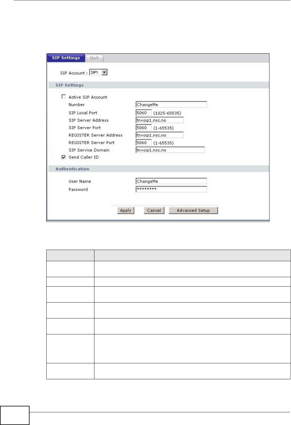
Use this screen to maintain basic information about each SIP account. You can
also enable and disable each SIP account. To access this screen, click VoIP > SIP
> SIP Settings.
Figure 118 VoIP > SIP > SIP Settings
Each field is described in the following table.
Table 49 VoIP > SIP > SIP Settings
LABEL DESCRIPTION
SIP Account Select the SIP account you want to see in this screen. If you change this
field, the screen automatically refreshes.
SIP Settings
Active SIP
Account Select this if you want the ZyXEL Device to use this account. Clear it if
you do not want the ZyXEL Device to use this account.
Number Enter your SIP number. In the full SIP URI, this is the part before the @
symbol. You can use up to 127 printable ASCII characters.
SIP Local Port Enter the ZyXEL Device’s listening port number, if your VoIP service
provider gave you one. Otherwise, keep the default value.
SIP Server
Address Enter the IP address or domain name of the SIP server provided by
your VoIP service provider. You can use up to 95 printable ASCII
characters. It does not matter whether the SIP server is a proxy,
redirect or register server.
SIP Server Port Enter the SIP server’s listening port number, if your VoIP service
provider gave you one. Otherwise, keep the default value.
Chapter 10 Voice
P-2612HWU-F1 User’s Guide 185
REGISTER
Server Address Enter the IP address or domain name of the SIP register server, if your
VoIP service provider gave you one. Otherwise, enter the same address
you entered in the SIP Server Address field. You can use up to 95
printable ASCII characters.
REGISTER
Server Port Enter the SIP register server’s listening port number, if your VoIP
service provider gave you one. Otherwise, enter the same port number
you entered in the SIP Server Port field.
SIP Service
Domain Enter the SIP service domain name. In the full SIP URI, this is the part
after the @ symbol. You can use up to 127 printable ASCII Extended
set characters.
Send Caller ID Select this if you want to send identification when you make VoIP phone
calls. Clear this if you do not want to send identification.
Authentication
User Name Enter the user name for registering this SIP account, exactly as it was
given to you. You can use up to 95 printable ASCII characters.
Password Enter the user name for registering this SIP account, exactly as it was
given to you. You can use up to 95 printable ASCII Extended set
characters.
Apply Click this to save your changes and to apply them to the ZyXEL Device.
Cancel Click this to set every field in this screen to its last-saved value.
Advanced Setup Click this to edit the advanced settings for this SIP account. The
Advanced SIP Setup screen appears.
Table 49 VoIP > SIP > SIP Settings
LABEL DESCRIPTION
Chapter 10 Voice
P-2612HWU-F1 User’s Guide
186
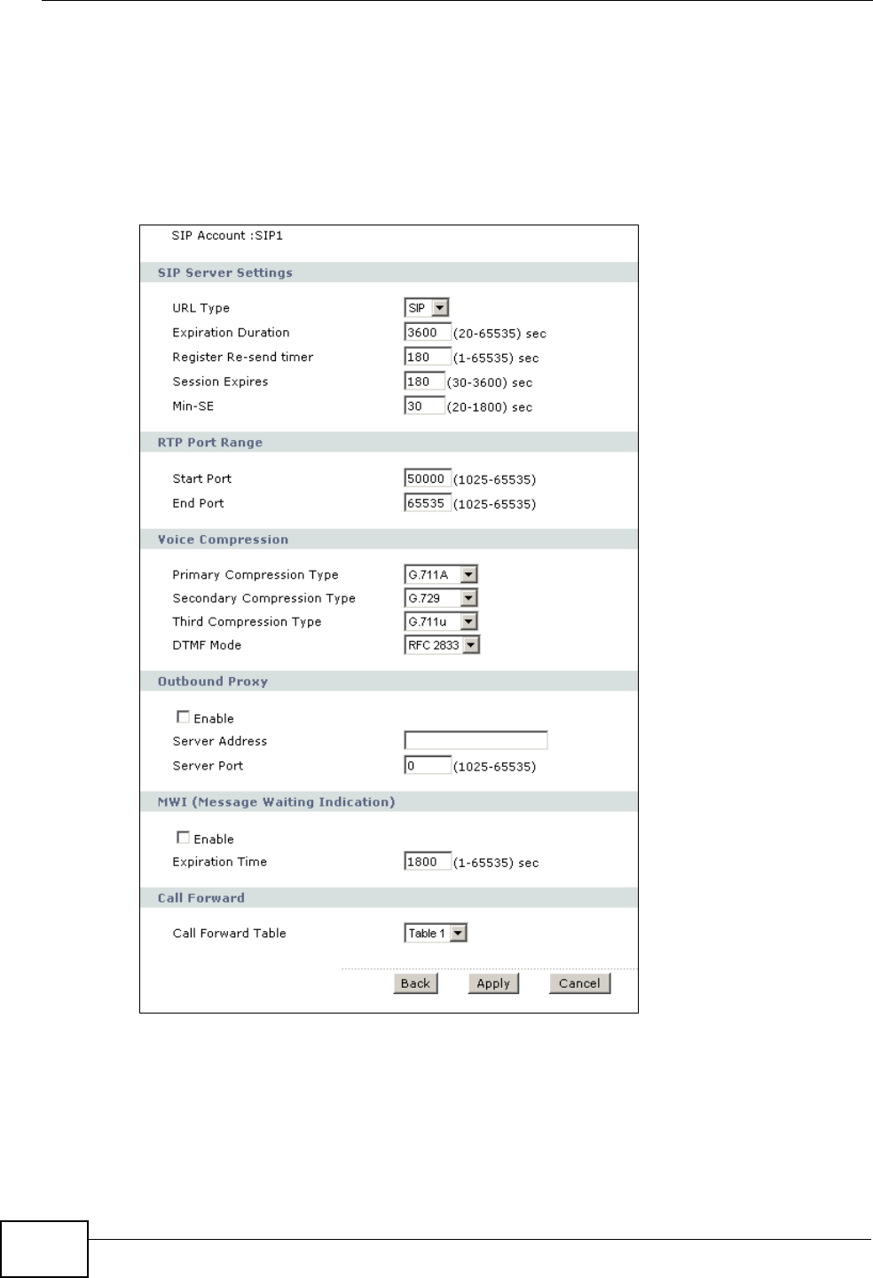
10.3 The Advanced SIP Setup Screen
Click VoIP > SIP > SIP Settings to open the SIP Settings screen. Select a SIP
account and click Advanced Setup to open the Advanced SIP Setup screen.
Use this screen to maintain advanced settings for each SIP account.
Figure 119 VoIP > SIP Settings > Advanced
Chapter 10 Voice
P-2612HWU-F1 User’s Guide 187
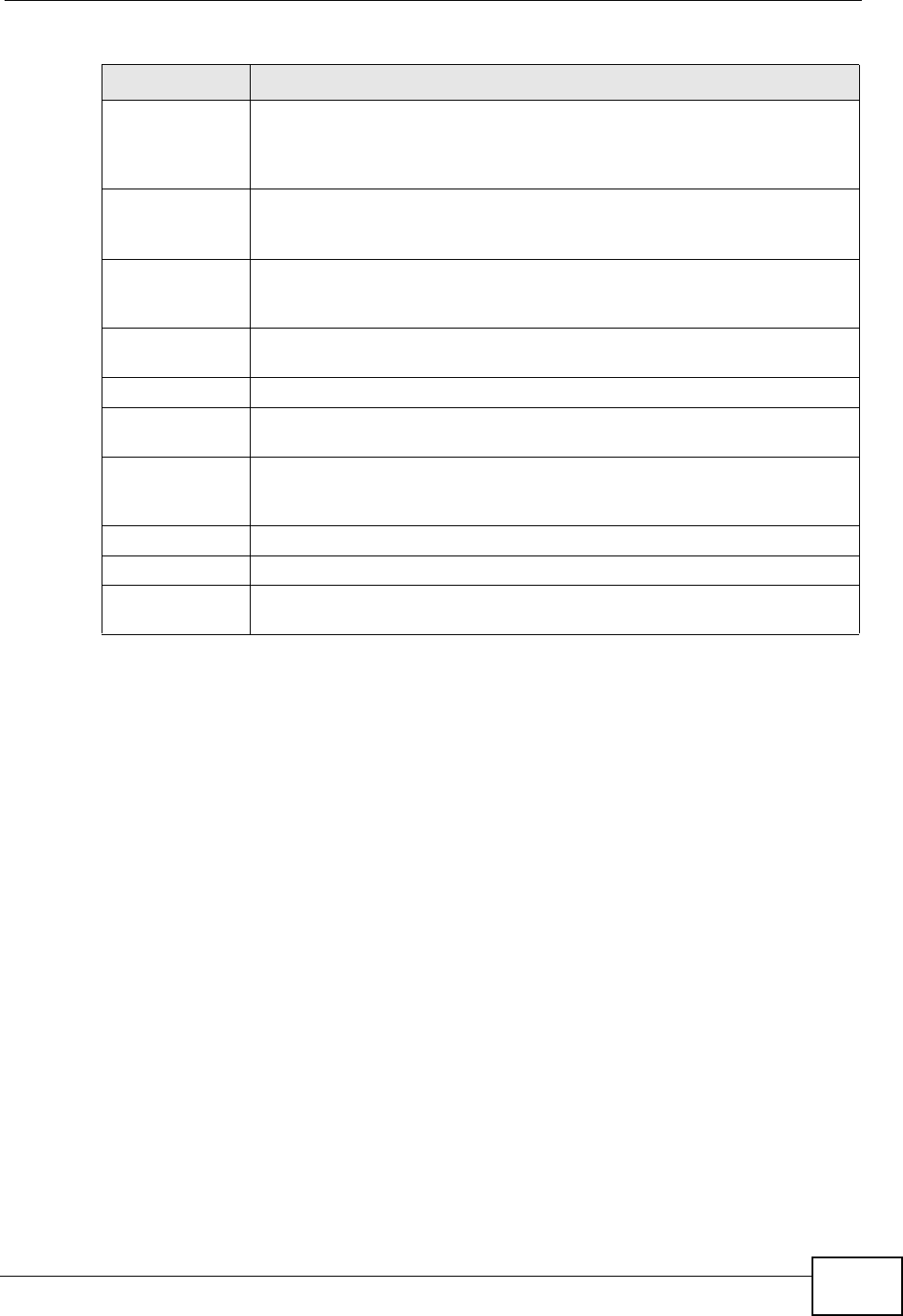
Each field is described in the following table.
Table 50 VoIP > SIP Settings > Advanced
LABEL DESCRIPTION
SIP Account This field displays the SIP account you see in this screen.
SIP Server
Settings
URL Type Select whether or not to include the SIP service domain name when the
ZyXEL Device sends the SIP number.
SIP - include the SIP service domain name.
TEL - do not include the SIP service domain name.
Expiration
Duration Enter the number of seconds your SIP account is registered with the
SIP register server before it is deleted. The ZyXEL Device automatically
tries to re-register your SIP account when one-half of this time has
passed. (The SIP register server might have a different expiration.)
Register Re-
send timer Enter the number of seconds the ZyXEL Device waits before it tries
again to register the SIP account, if the first try failed or if there is no
response.
Session Expires Enter the number of seconds the ZyXEL Device lets a SIP session
remain idle (without traffic) before it automatically disconnects the
session.
Min-SE Enter the minimum number of seconds the ZyXEL Device lets a SIP
session remain idle (without traffic) before it automatically disconnects
the session. When two SIP devices start a SIP session, they must agree
on an expiration time for idle sessions. This field is the shortest
expiration time that the ZyXEL Device accepts.
RTP Port Range
Start Port
End Port
Enter the listening port number(s) for RTP traffic, if your VoIP service
provider gave you this information. Otherwise, keep the default values.
To enter one port number, enter the port number in the Start Port and
End Port fields.
To enter a range of ports,
• enter the port number at the beginning of the range in the Start
Port field.
• enter the port number at the end of the range in the End Port field.
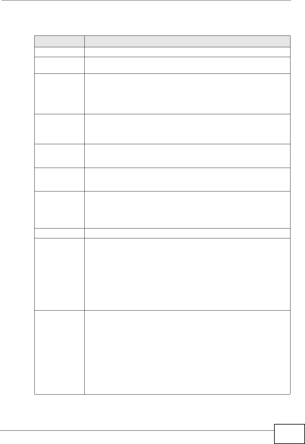
Voice
Compression Select the type of voice coder/decoder (codec) that you want the ZyXEL
Device to use. G.711 provides higher voice quality but requires more
bandwidth (64 kbps).
•G.711A is typically used in Europe.
•G.711u is typically used in North America and Japan.
G.726 operates at 16, 24, 32 or 40 kbps.
By contrast, G.729 only requires 8 kbps.
The ZyXEL Device must use the same codec as the peer. When two SIP
devices start a SIP session, they must agree on a codec.
Chapter 10 Voice
P-2612HWU-F1 User’s Guide
188
Primary
Compression
Type
Select the ZyXEL Device’s first choice for voice coder/decoder.
Secondary
Compression
Type
Select the ZyXEL Device’s second choice for voice coder/decoder. Select
None if you only want the ZyXEL Device to accept the first choice.
Third
Compression
Type
Select the ZyXEL Device’s third choice for voice coder/decoder. Select
None if you only want the ZyXEL Device to accept the first or second
choice.
DTMF Mode Control how the ZyXEL Device handles the tones that your telephone
makes when you push its buttons. You should use the same mode your
VoIP service provider uses.
RFC 2833 - send the DTMF tones in RTP packets.
PCM - send the DTMF tones in the voice data stream. This method
works best when you are using a codec that does not use compression
(like G.711). Codecs that use compression (like G.729 and G.726) can
distort the tones.
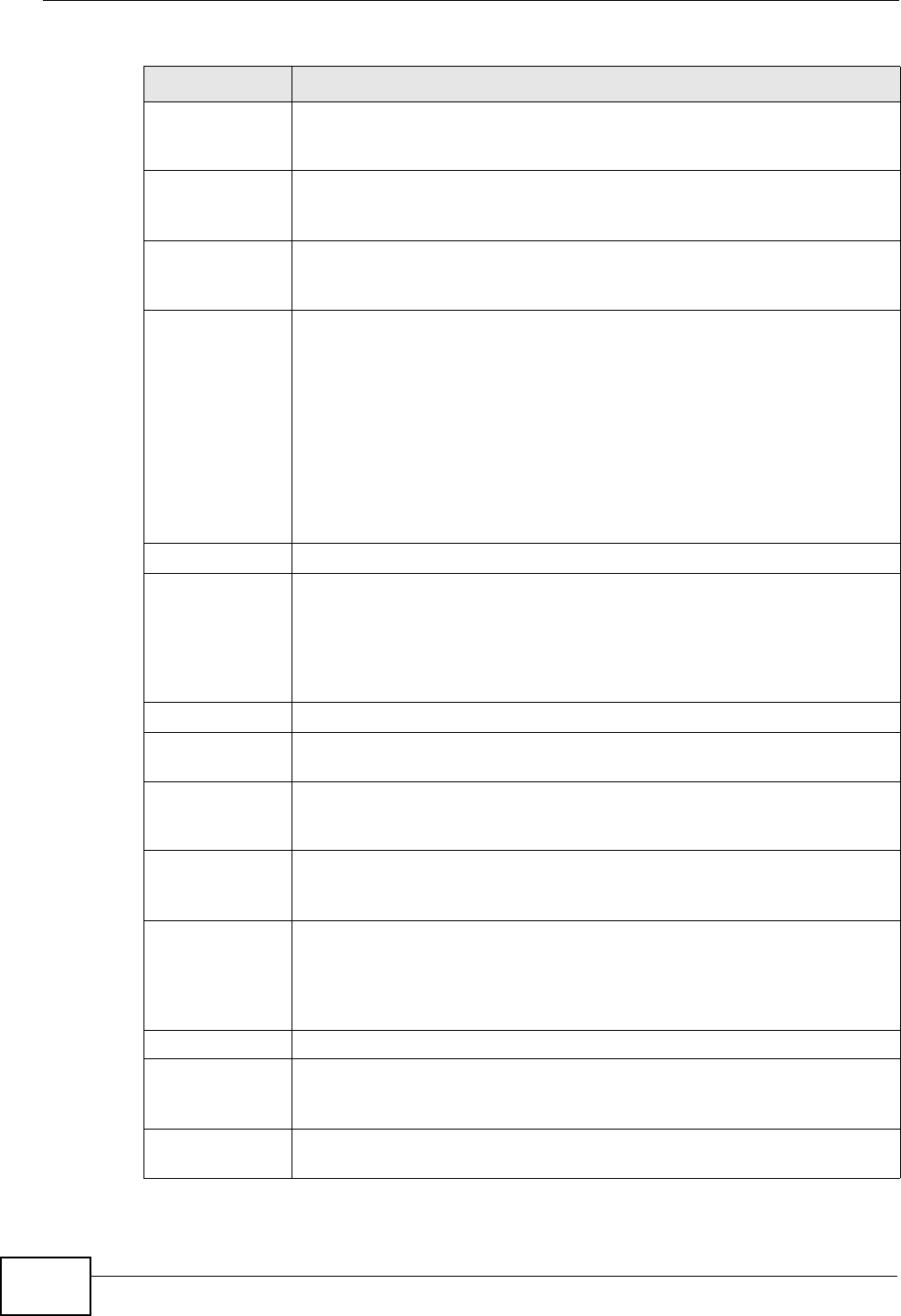
SIP INFO - send the DTMF tones in SIP messages.
Outbound Proxy
Enable Select this if your VoIP service provider has a SIP outbound server to
handle voice calls. This allows the ZyXEL Device to work with any type
of NAT router and eliminates the need for STUN or a SIP ALG. Turn off
any SIP ALG on a NAT router in front of the ZyXEL Device to keep it
from re-translating the IP address (since this is already handled by the
outbound proxy server).
Server Address Enter the IP address or domain name of the SIP outbound proxy server.
Server Port Enter the SIP outbound proxy server’s listening port, if your VoIP
service provider gave you one. Otherwise, keep the default value.
MWI (Message
Waiting
Indication)
Enable Select this if you want to hear a waiting (beeping) dial tone on your
phone when you have at least one voice message. Your VoIP service
provider must support this feature.
Expiration Time Keep the default value for this field, unless your VoIP service provider
tells you to change it. Enter the number of seconds the SIP server
should provide the message waiting service each time the ZyXEL Device
subscribes to the service. Before this time passes, the ZyXEL Device
automatically subscribes again.
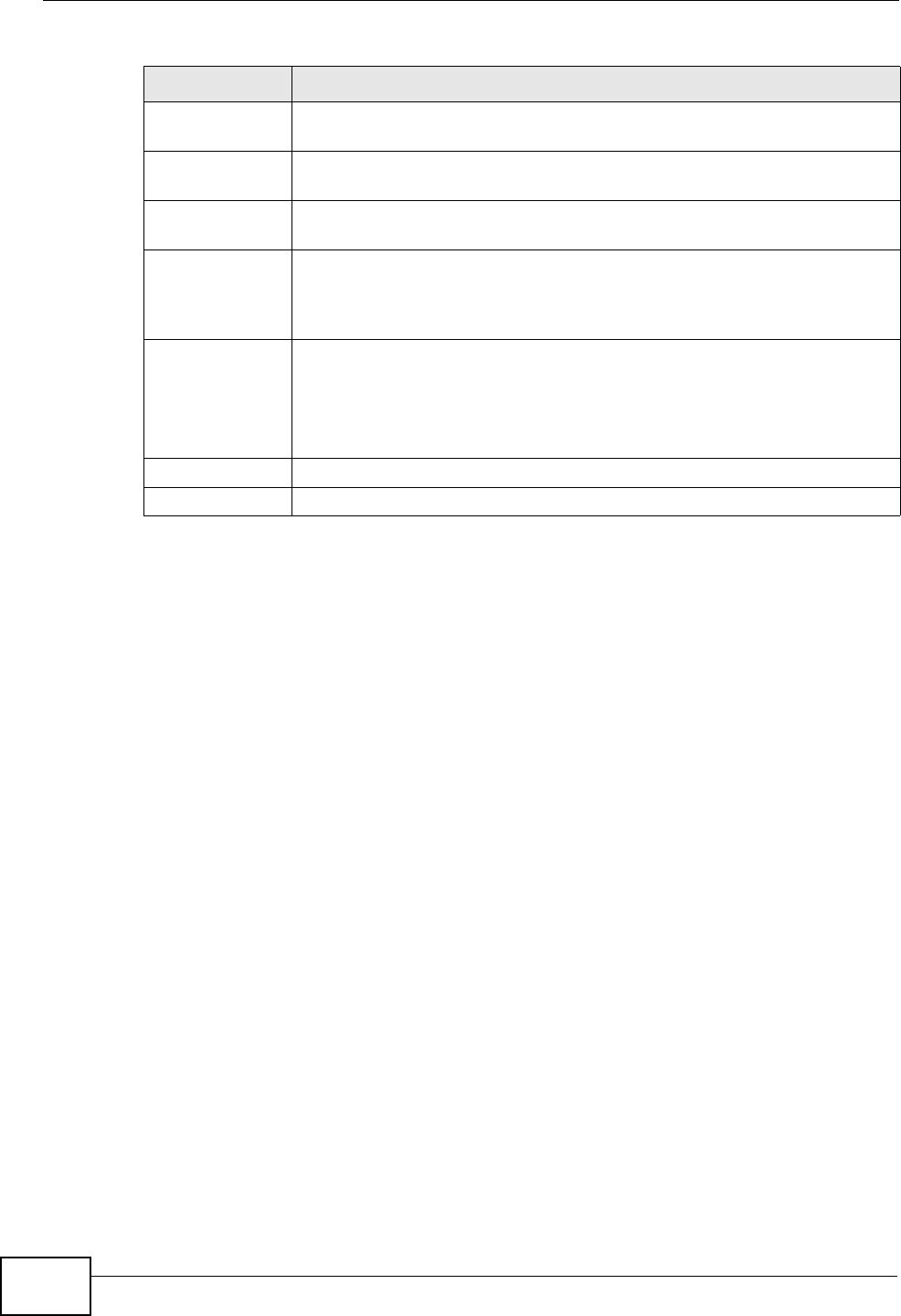
Call Forward
Call Forward
Table Select which call forwarding table you want the ZyXEL Device to use for
incoming calls. You set up these tables in VoIP > Phone Book >
Incoming Call Policy.
Back Click this to return to the SIP Settings screen without saving your
changes.
Table 50 VoIP > SIP Settings > Advanced
LABEL DESCRIPTION
Chapter 10 Voice
P-2612HWU-F1 User’s Guide 189
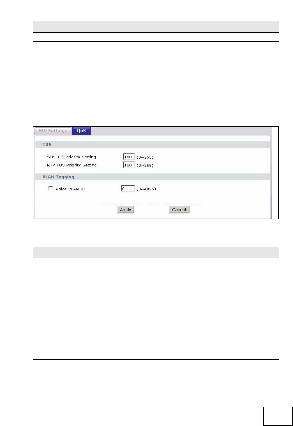
10.4 The SIP QoS Screen
Use this screen to maintain ToS and VLAN settings for the ZyXEL Device. To access
this screen, click VoIP > SIP > QoS.
Figure 120 VoIP > SIP > QoS
Each field is described in the following table.
Apply Click this to save your changes and to apply them to the ZyXEL Device.
Cancel Click this to set every field in this screen to its last-saved value.
Table 50 VoIP > SIP Settings > Advanced
LABEL DESCRIPTION
Table 51 VoIP > SIP > QoS
LABEL DESCRIPTION
SIP TOS Priority
Setting Enter the priority for SIP voice transmissions. The ZyXEL Device creates
Type of Service priority tags with this priority to voice traffic that it
transmits.
RTP TOS
Priority Setting Enter the priority for RTP voice transmissions. The ZyXEL Device creates
Type of Service priority tags with this priority to RTP traffic that it
transmits.
Voice VLAN ID Select this if the ZyXEL Device has to be a member of a VLAN to
communicate with the SIP server. Ask your network administrator, if
you are not sure. Enter the VLAN ID provided by your network
administrator in the field on the right. Your LAN and gateway must be
configured to use VLAN tags.
Otherwise, clear this field.
Apply Click this to save your changes and to apply them to the ZyXEL Device.
Cancel Click this to set every field in this screen to its last-saved value.
Chapter 10 Voice
P-2612HWU-F1 User’s Guide
190
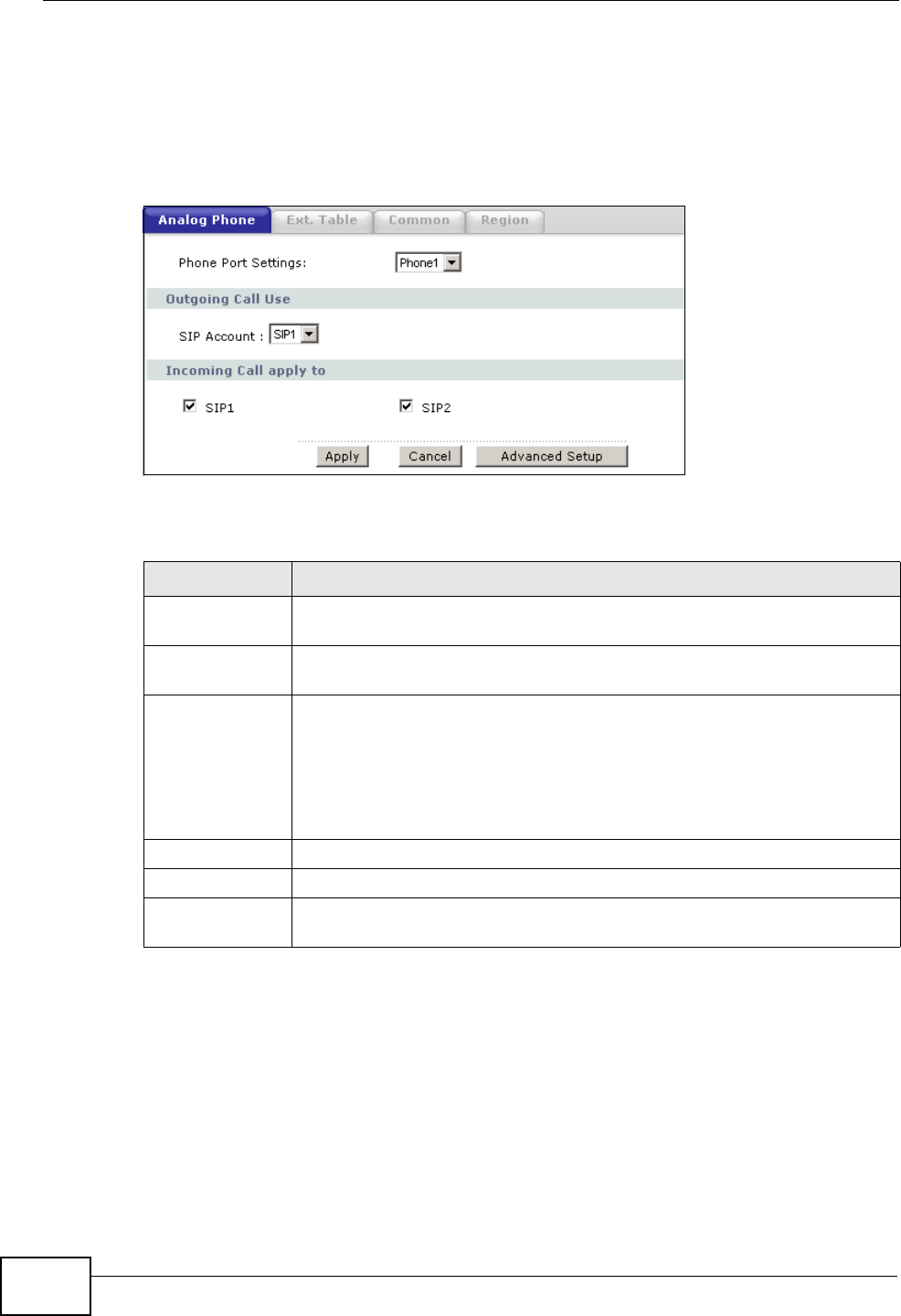
10.5 The Analog Phone Screen
Use this screen to control which SIP accounts and PSTN line each phone uses. To
access this screen, click VoIP > Phone > Analog Phone.
Figure 121 VoIP > Phone > Analog Phone
Each field is described in the following table.
10.6 The Advanced Analog Phone Setup Screen
Use this screen to configure the volume, echo cancellation and VAD (Voice Activity
Detection) settings for each individual phone port on the ZyXEL Device. You can
also select which SIP account to use for making outgoing calls.
Table 52 VoIP > Phone > Analog Phone
LABEL DESCRIPTION
Phone Port
Settings This is the phone port in the ZyXEL Device.
SIP Account Select the SIP account you want to use when making outgoing calls
with the analog phone connected to this phone port.
Incoming Call
apply to Select a SIP account if you want to receive phone calls for the selected
SIP account on this phone port.
If you select more than one SIP account for incoming calls, there is no
way to distinguish between them when you receive phone calls. If you
do not select a source for incoming calls, you cannot receive any calls
on this phone port.
Apply Click this to save your changes and to apply them to the ZyXEL Device.
Cancel Click this to set every field in this screen to its last-saved value.
Advanced Setup Click this to edit the advanced settings for this phone port. The
Advanced Analog Phone Setup screen appears.
Chapter 10 Voice
P-2612HWU-F1 User’s Guide 191
Voice Activity Detection/Silence Suppression
Voice Activity Detection (VAD) detects whether or not speech is present. This lets
the ZyXEL Device reduce the bandwidth that a call uses by not transmitting “silent
packets” when you are not speaking.
Comfort Noise Generation
When using VAD, the ZyXEL Device generates comfort noise when the other party
is not speaking. The comfort noise lets you know that the line is still connected as
total silence could easily be mistaken for a lost connection.
Echo Cancellation
G.168 is an ITU-T standard for eliminating the echo caused by the sound of your
voice reverberating in the telephone receiver while you talk.
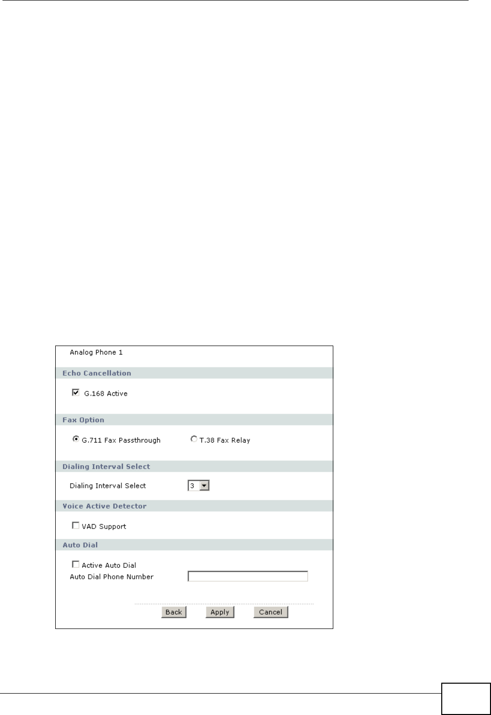
10.6.1 Configuring the Advanced Analog Phone Screen
To access this screen, click Advanced Setup in VoIP > Phone > Analog
Phone.
Figure 122 VoIP > Phone > Analog Phone > Advanced
Chapter 10 Voice
P-2612HWU-F1 User’s Guide
192
Each field is described in the following table.
Table 53 VoIP > Phone > Analog Phone > Advanced
LABEL DESCRIPTION
Analog Phone This field displays the analog phone port you see in this screen.
Echo
Cancellation
Active G.168 Select this if you want to eliminate the echo caused by the sound of
your voice reverberating in the telephone receiver while you talk.
Fax Option This field controls how the ZyXEL Device handles fax messages.
G.711 Fax
Passthrough Select this if the ZyXEL Device should use G.711 to send fax messages.
The peer devices must also use G.711.
T.38 Fax Relay Select this if the ZyXEL Device should send fax messages as UDP or
TCP/IP packets through IP networks. This provides better quality, but it
may have inter-operability problems. The peer devices must also use
T.38.
Dialing Interval
Selection
Dialing Interval
Selection Enter the number of seconds the ZyXEL Device should wait after you
stop dialing numbers before it makes the phone call. The value depends
on how quickly you dial phone numbers.
If you select Active Immediate Dial in VoIP > Phone > Common,
you can press the pound key (#) to tell the ZyXEL Device to make the
phone call immediately, regardless of this setting.
Voice Active
Detector
VAD Support Select this if the ZyXEL Device should stop transmitting when you are
not speaking. This reduces the bandwidth the ZyXEL Device uses.
Auto Dial
Active Auto Dial Select this if you want the ZyXEL Device to automatically dial the phone
number you enter in the Auto Dial Phone Number field as soon as
you take the phone off the hook.
Auto Dial Phone
Number If you select Active Auto Dial, enter the phone number you want the
ZyXEL Device to automatically dial in this field.
Back Click this to return to the Analog Phone screen without saving your
changes.
Apply Click this to save your changes.
Cancel Click this to set every field in this screen to its last-saved value.
Chapter 10 Voice
P-2612HWU-F1 User’s Guide 193
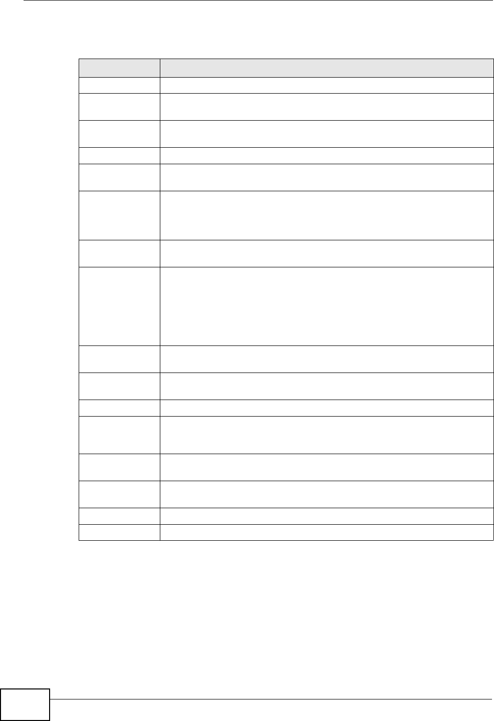
10.7 The Phone Settings Ext. Table Screen
Each phone connected to the ZyXEL Device has an extension number so that it
can be separately identified for intercom use. The default settings of extension
numbers are shown in the following table.
An extension number is composed of a group number and a sub number. If group
number is not enabled, the extension number is simply the sub number. You can
assign a group number to several phones and use this number to call the group of
phones. When you dial a group number, all of the phones with the same group
number ring. The phone that picks up first gets the line, and the other phones
stop ringing.
Click VoIP > Phone > Ext. Table to access this screen.
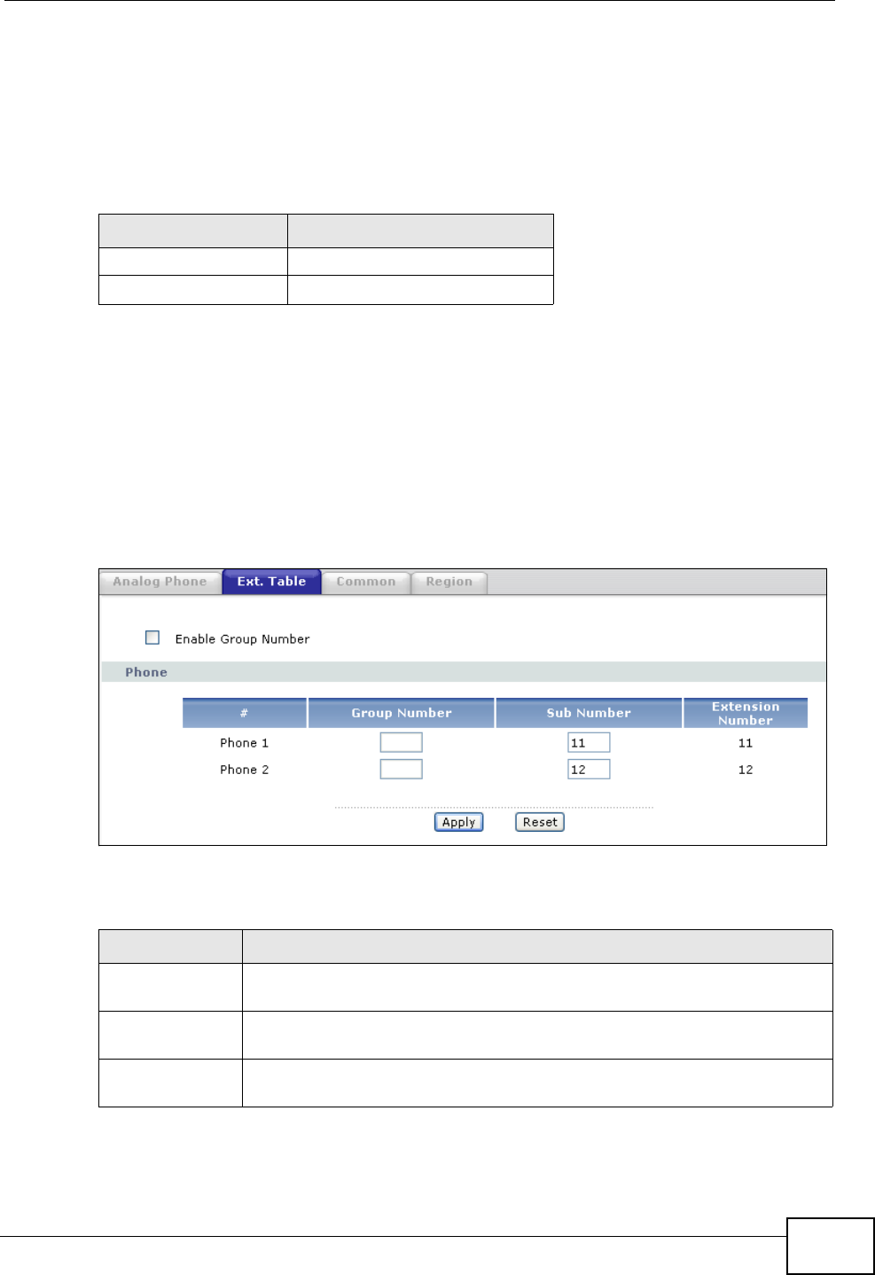
Figure 123 VoIP > Phone > Ext. Table
Each field is described in the following table.
Table 54 Default Ext. Numbers
PHONE DEFAULT EXT. NUMBER
Analog Phone 1 11
Analog Phone 2 12
Table 55 VoIP > Phone > Ext. Table
LABEL DESCRIPTION
Enable Group
Number Select this if you want to enable group number for the DECT and analog
phones connected to the ZyXEL Device.
Phone Use these fields to assign extension numbers to the phones connected
to the ZyXEL Device.
#This is an index number of the phone to be assigned an extension
number.
Chapter 10 Voice
P-2612HWU-F1 User’s Guide
194
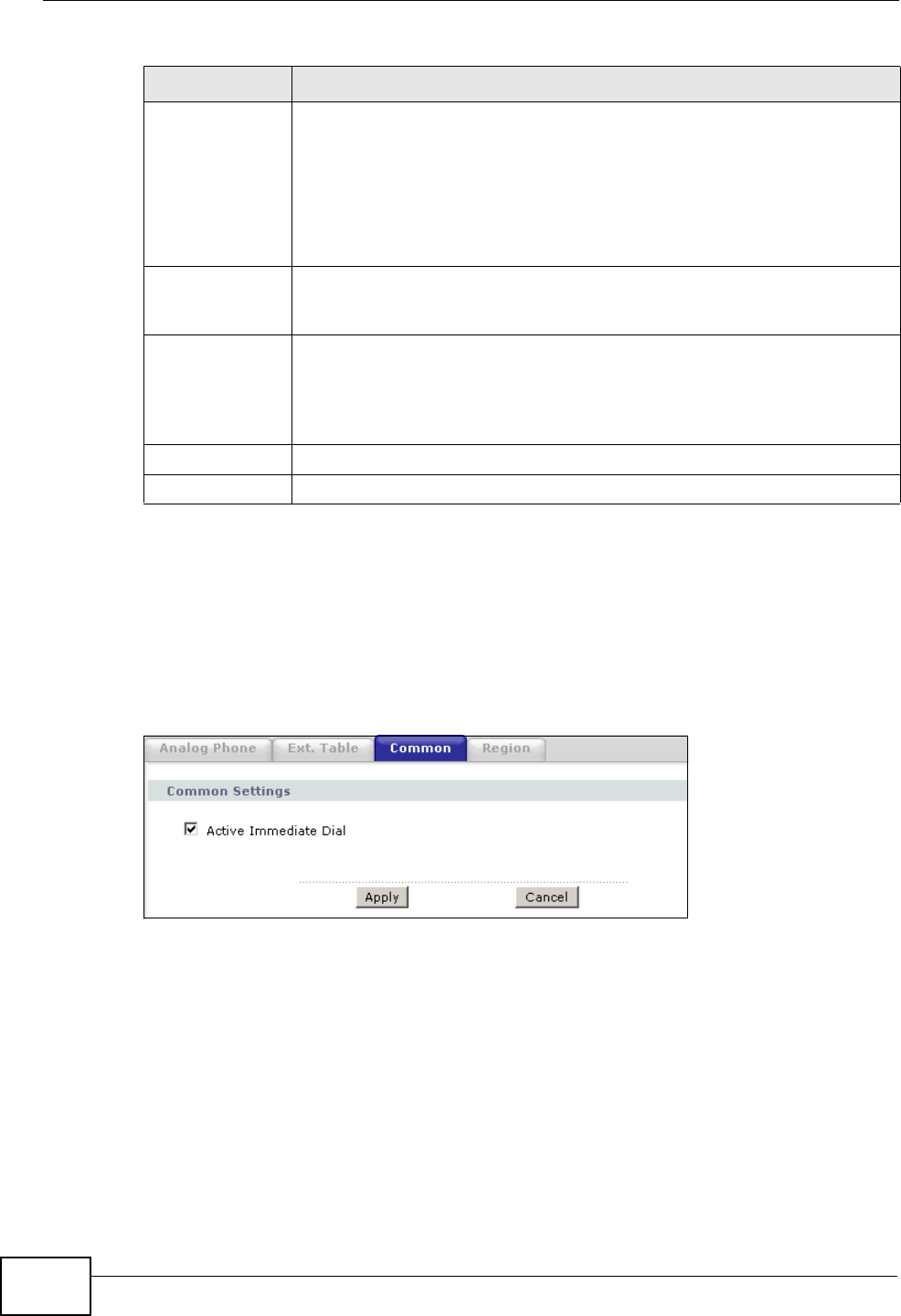
10.8 The Common Phone Settings Screen
Use this screen to activate and deactivate immediate dialing. To access this
screen, click VoIP > Phone > Common.
Figure 124 VoIP > Phone > Common
Group
Number Enter a group number for this phone. The maximum length of a group
number is one digit. This is only available when the check box of
Enable Group Number is selected.
For example, you can assign Phone 1 and Phone 2 a group number “5”
and leave the sub numbers at default (“11” and “12”). When you dial
“5”, both Phone 1 and Phone 2 ring. If Phone 1 picks up the line first, it
gets the line and Phone 2 stops ringing.
Sub Number Enter a sub number for this phone. The maximum length of a sub
number is two digits. When the check box of Enable Group Number is
not selected, the extension number is simply the sub number.
Extension
Number This read-only field displays the extension number which is a
combination of “Group Number” and “Sub Number“. When you change
group number or sub number, the extension number automatically
refreshes. Use extension number to make calls between phones
connected to the ZyXEL Device.
Apply Click this to save your changes and to apply them to the ZyXEL Device.
Cancel Click this to set every field in this screen to its last-saved value.
Table 55 VoIP > Phone > Ext. Table
LABEL DESCRIPTION
Chapter 10 Voice
P-2612HWU-F1 User’s Guide 195
Each field is described in the following table.
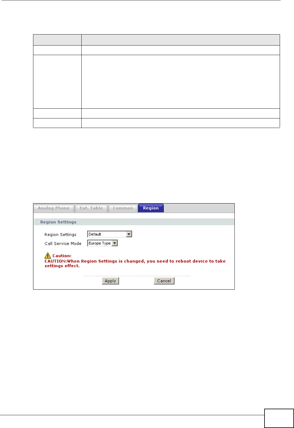
10.9 The Phone Region Screen
Use this screen to maintain settings that depend on which region of the world the
ZyXEL Device is in. To access this screen, click VoIP > Phone > Region.
Figure 125 VoIP > Phone > Region
Table 56 VoIP > Phone > Common
LABEL DESCRIPTION
Immediate Dial
Active
Immediate Dial Select this if you want to use the pound key (#) to tell the ZyXEL Device
to make the phone call immediately, instead of waiting the number of
seconds you selected in the Dialing Interval Selection in VoIP >
Phone > Analog Phone > Advanced Setup.
If you select this, dial the phone number, and then press the pound key.
The ZyXEL Device makes the call immediately, instead of waiting. You
can still wait, if you want.
Apply Click this to save your changes and to apply them to the ZyXEL Device.
Cancel Click this to set every field in this screen to its last-saved value.
Chapter 10 Voice
P-2612HWU-F1 User’s Guide
196
Each field is described in the following table.
10.10 The Speed Dial Screen
Use this screen to add, edit, or remove speed-dial numbers for outgoing calls.
Speed dial provides shortcuts for dialing frequently-used (VoIP) phone numbers.
You also have to create speed-dial entries if you want to make peer-to-peer calls
or call SIP numbers that contain letters. Once you have configured a speed dial
rule, you can use a shortcut (the speed dial number, #01 for example) on your
phone's keypad to call the phone number.
In peer-to-peer calls, you call another VoIP device directly without going through a
VoIP service provider’s SIP server. Select Non-Proxy (Use IP or URL) in the
Type column and enter the callee’s IP address or domain name. The ZyXEL Device
Table 57 VoIP > Phone > Region
LABEL DESCRIPTION
Region Settings Select the place in which the ZyXEL Device is located.
Call Service
Mode Select the mode for supplementary phone services (call hold, call
waiting, call transfer and three-way conference calls) that your VoIP
service provider supports.
Europe Type - use supplementary phone services in European mode
USA Type - use supplementary phone services American mode
You might have to subscribe to these services to use them. Contact your
VoIP service provider.
Apply Click this to save your changes and to apply them to the ZyXEL Device.
Cancel Click this to set every field in this screen to its last-saved value.
Chapter 10 Voice
P-2612HWU-F1 User’s Guide 197
sends SIP INVITE requests to the peer VoIP device when you use the speed dial
entry.
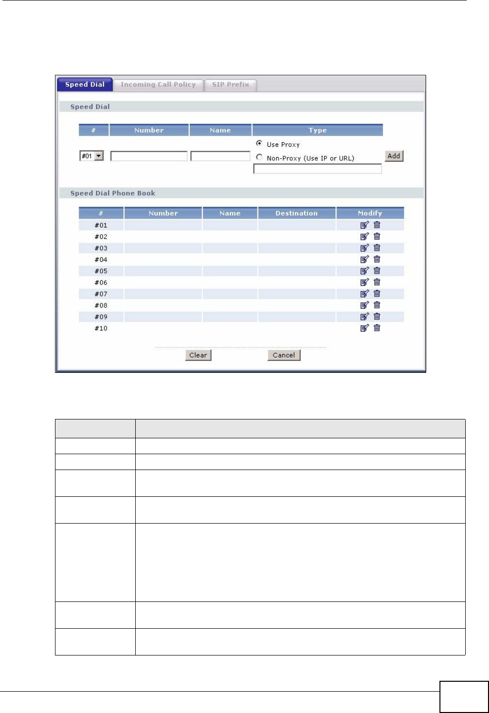
Figure 126 Phone Book > Speed Dial
Each field is described in the following table.
Table 58 Phone Book > Speed Dial
LABEL DESCRIPTION
Speed Dial Use this section to create or edit speed-dial entries.
#Select the speed-dial number you want to use for this phone number.
Number Enter the SIP number you want the ZyXEL Device to call when you dial
the speed-dial number.
Name Enter a name to identify the party you call when you dial the speed-dial
number. You can use up to 127 printable ASCII characters.
Type Select Use Proxy if you want to use one of your SIP accounts to call
this phone number.
Select Non-Proxy (Use IP or URL) if you want to use a different SIP
server or if you want to make a peer-to-peer call. In this case, enter the
IP address or domain name of the SIP server or the other party in the
field below.
Add Click this to use the information in the Speed Dial section to update
the Speed Dial Phone Book section.
Speed Dial
Phone Book Use this section to look at all the speed-dial entries and to erase them.
Chapter 10 Voice
P-2612HWU-F1 User’s Guide
198
# This field displays the speed-dial number you should dial to use this
entry.
Number This field displays the SIP number the ZyXEL Device calls when you dial
the speed-dial number.
Name This field displays the name of the party you call when you dial the
speed-dial number.
Destination This field is blank, if the speed-dial entry uses one of your SIP accounts.
Otherwise, this field shows the IP address or domain name of the SIP
server or other party. (This field corresponds with the Type field in the
Speed Dial section.)
Modify Use this field to edit or erase the speed-dial entry.
Click the Edit icon to copy the information for this speed-dial entry into
the Speed Dial section, where you can change it.
Click the Remove icon to erase this speed-dial entry.
Clear Click this to erase all the speed-dial entries.
Cancel Click this to set every field in this screen to its last-saved value.
Table 58 Phone Book > Speed Dial
LABEL DESCRIPTION
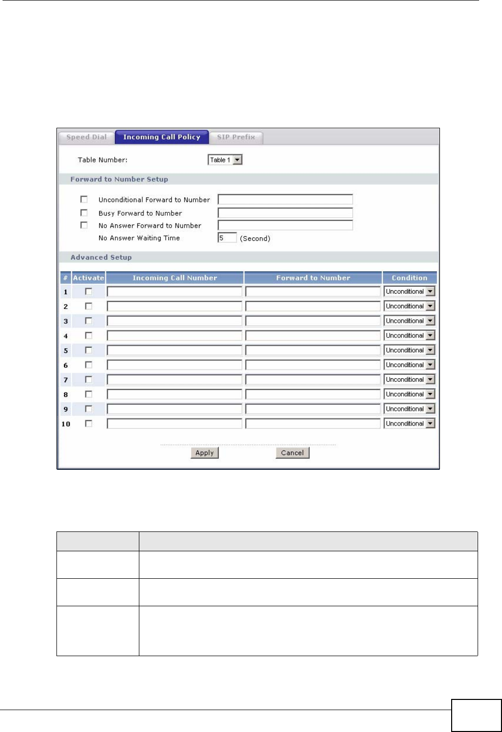
Chapter 10 Voice
P-2612HWU-F1 User’s Guide 199
10.11 Incoming Call Policy Screen
Use this screen to maintain rules for handling incoming calls. You can block,
redirect, or accept them. To access this screen, click VoIP > Phone Book >
Incoming Call Policy.
Figure 127 Phone Book > Incoming Call Policy
You can create two sets of call-forwarding rules. Each one is stored in a call-
forwarding table. Each field is described in the following table.
Table 59 Phone Book > Incoming Call Policy
LABEL DESCRIPTION
Table Number Select the call-forwarding table you want to see in this screen. If you
change this field, the screen automatically refreshes.
Forward to
Number Setup The ZyXEL Device checks these rules, in the order in which they appear,
after it checks the rules in the Advanced Setup section.
Unconditional
Forward to
Number
Select this if you want the ZyXEL Device to forward all incoming calls to
the specified phone number, regardless of other rules in the Forward
to Number Setup section. Specify the phone number in the field on
the right.

Chapter 10 Voice
P-2612HWU-F1 User’s Guide
200
Busy Forward to
Number Select this if you want the ZyXEL Device to forward incoming calls to
the specified phone number if the phone port is busy. Specify the phone
number in the field on the right. If you have call waiting, the incoming
call is forwarded to the specified phone number if you reject or ignore
the second incoming call.
No Answer
Forward to
Number
Select this if you want the ZyXEL Device to forward incoming calls to
the specified phone number if the call is unanswered. (See No Answer
Waiting Time.) Specify the phone number in the field on the right.
No Answer
Waiting Time This field is used by the No Answer Forward to Number feature and
No Answer conditions below.
Enter the number of seconds the ZyXEL Device should wait for you to
answer an incoming call before it considers the call is unanswered.
Advanced Setup The ZyXEL Device checks these rules after it checks the rules in the
Forward to Number Setup section.
# This field is a sequential value, and it is not associated with a specific
rule. The sequence is important, however. The ZyXEL Device checks
each rule in order, and it only follows the first one that applies.
Activate Select this to enable this rule. Clear this to disable this rule.
Incoming Call
Number Enter the phone number to which this rule applies.
Forward to
Number Enter the phone number to which you want to forward incoming calls
from the Incoming Call Number. You may leave this field blank,
depending on the Condition.
Condition Select the situations in which you want to forward incoming calls from
the Incoming Call Number, or select an alternative action.
Unconditional - The ZyXEL Device immediately forwards any calls
from the Incoming Call Number to the Forward to Number.
Busy - The ZyXEL Device forwards any calls from the Incoming Call
Number to the Forward to Number when your SIP account already
has a call connected.
No Answer - The ZyXEL Device forwards any calls from the Incoming
Call Number to the Forward to Number when the call is unanswered.
(See No Answer Waiting Time.)
Block - The ZyXEL Device rejects calls from the Incoming Call
Number.
Accept - The ZyXEL Device allows calls from the Incoming Call
Number. You might create a rule with this condition if you do not want
incoming calls from someone to be forwarded by rules in the Forward
to Number section.
Apply Click this to save your changes and to apply them to the ZyXEL Device.
Cancel Click this to set every field in this screen to its last-saved value.
Table 59 Phone Book > Incoming Call Policy
LABEL DESCRIPTION
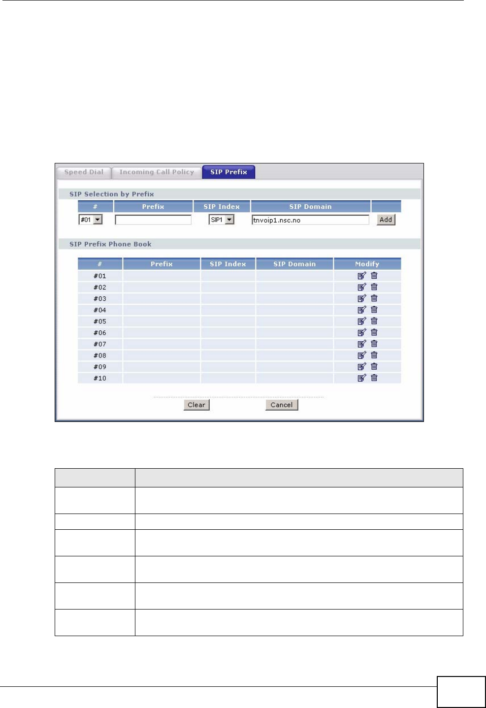
Chapter 10 Voice
P-2612HWU-F1 User’s Guide 201
10.12 SIP Prefix Screen
The SIP prefix screen allows you to set up numbers you dial on your phone to
specify which SIP account you want to use for a call. If you dial only the phone
number (no prefix number) the ZyXEL Device uses default SIP settings to make
the call.
Click VoIP > Phone Book > SIP Prefix. The following screen displays.
Figure 128 Phone Book > SIP Prefix
Each field is described in the following table.
Table 60 Phone Book > SIP Prefix
LABEL DESCRIPTION
SIP Selection by
Prefix
#Select the index number of the rule you want to edit.
Prefix Enter the prefix number (1 ~ 8 digits). This is the number you dial
before you dial the phone number.
SIP Index Select the SIP account you want to use to make outgoing calls when
you dial the number in the Prefix field.
SIP Domain This field displays the SIP service domain name you entered when
configuring this SIP account.
Add Click this to use the information in the SIP Selection by Prefix section
to update the SIP Prefix Phone Book section.
Chapter 10 Voice
P-2612HWU-F1 User’s Guide
202
10.13 SIP Technical Reference
This section contains background material relevant to the VoIP > SIP screens.
10.13.1 VoIP
VoIP is the sending of voice signals over Internet Protocol. This allows you to
make phone calls and send faxes over the Internet at a fraction of the cost of
using the traditional circuit-switched telephone network. You can also use servers
to run telephone service applications like PBX services and voice mail. Internet
Telephony Service Provider (ITSP) companies provide VoIP service.
Circuit-switched telephone networks require 64 kilobits per second (Kbps) in each
direction to handle a telephone call. VoIP can use advanced voice coding
techniques with compression to reduce the required bandwidth.
10.13.2 SIP
The Session Initiation Protocol (SIP) is an application-layer control (signaling)
protocol that handles the setting up, altering and tearing down of voice and
multimedia sessions over the Internet.
SIP signaling is separate from the media for which it handles sessions. The media
that is exchanged during the session can use a different path from that of the
SIP Prefix
Phone Book This section displays all SIP prefix numbers currently configured on the
ZyXEL Device.
#This is a read-only index number.
Prefix This field displays the SIP prefix number you dial (before you dial the
phone number) in order to use the SIP account specified in the SIP
Index field.
SIP Index This field displays the SIP account used to make outgoing calls when
you dial the number in the Prefix field.
SIP Domain This field displays the SIP domain of the corresponding SIP account.
Modify Use this field to edit or erase the SIP prefix entry.
Click the Edit icon to copy the information for this SIP prefix entry into
the SIP Prefix section, where you can change it.
Click the Remove icon to erase this SIP prefix entry.
Clear Click this to erase all the SIP prefix entries.
Cancel Click this to set every field in this screen to its last-saved value.
Table 60 Phone Book > SIP Prefix
LABEL DESCRIPTION

Chapter 10 Voice
P-2612HWU-F1 User’s Guide 203
signaling. SIP handles telephone calls and can interface with traditional circuit-
switched telephone networks.
SIP Identities
A SIP account uses an identity (sometimes referred to as a SIP address). A
complete SIP identity is called a SIP URI (Uniform Resource Identifier). A SIP
account's URI identifies the SIP account in a way similar to the way an e-mail
address identifies an e-mail account. The format of a SIP identity is SIP-
Number@SIP-Service-Domain.
SIP Number
The SIP number is the part of the SIP URI that comes before the “@” symbol. A
SIP number can use letters like in an e-mail address (johndoe@your-ITSP.com for
example) or numbers like a telephone number (1122334455@VoIP-provider.com
for example).
SIP Service Domain
The SIP service domain of the VoIP service provider is the domain name in a SIP
URI. For example, if the SIP address is 1122334455@VoIP-provider.com, then
“VoIP-provider.com” is the SIP service domain.
SIP Registration
Each ZyXEL Device is an individual SIP User Agent (UA). To provide voice service,
it has a public IP address for SIP and RTP protocols to communicate with other
servers.
A SIP user agent has to register with the SIP registrar and must provide
information about the users it represents, as well as its current IP address (for the
routing of incoming SIP requests). After successful registration, the SIP server
knows that the users (identified by their dedicated SIP URIs) are represented by
the UA, and knows the IP address to which the SIP requests and responses should
be sent.
Registration is initiated by the User Agent Client (UAC) running in the VoIP
gateway (the ZyXEL Device). The gateway must be configured with information
letting it know where to send the REGISTER message, as well as the relevant user
and authorization data.
A SIP registration has a limited lifespan. The User Agent Client must renew its
registration within this lifespan. If it does not do so, the registration data will be
deleted from the SIP registrar's database and the connection broken.
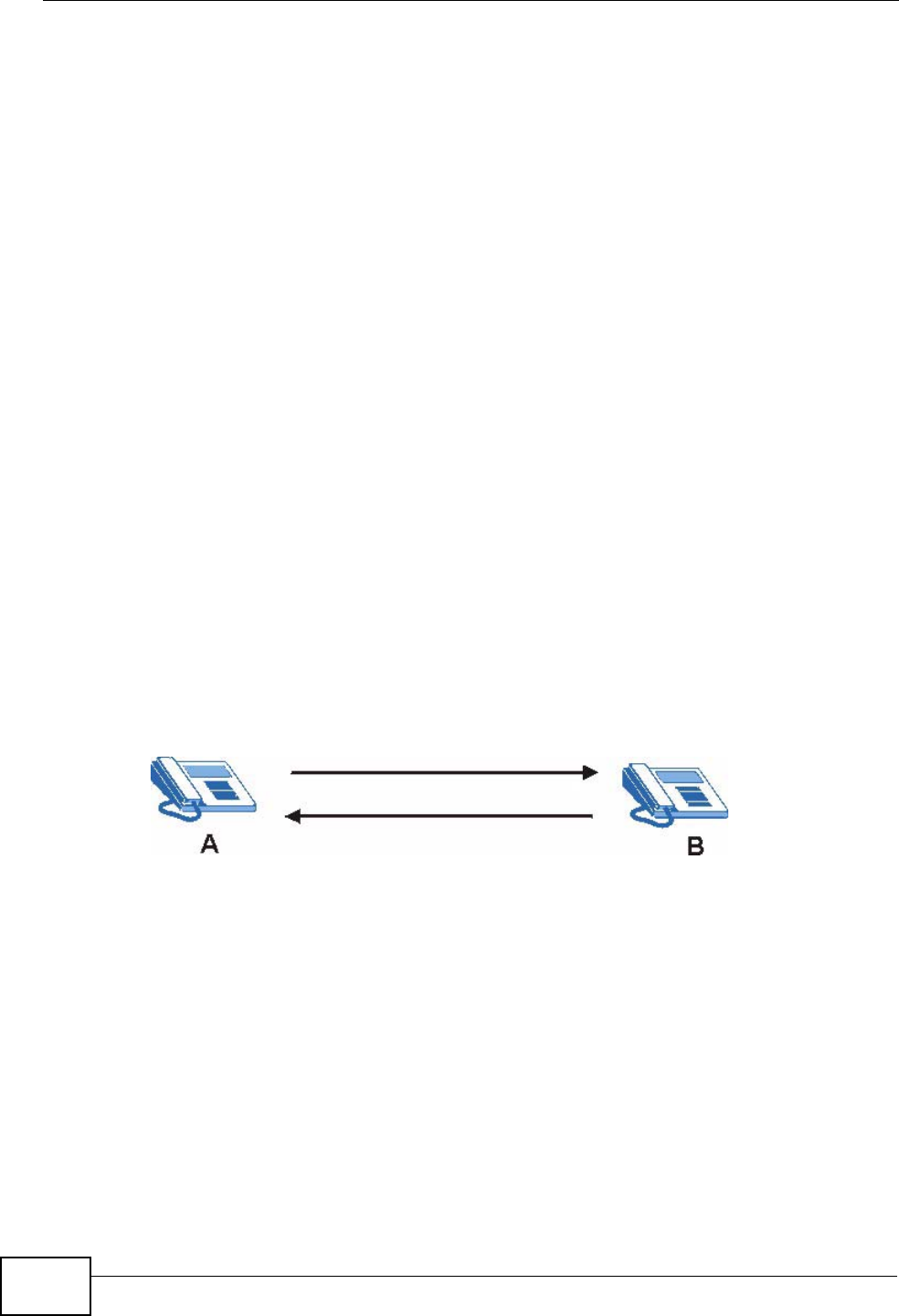
Chapter 10 Voice
P-2612HWU-F1 User’s Guide
204
The ZyXEL Device attempts to register all enabled subscriber ports when it is
switched on. When you enable a subscriber port that was previously disabled, the
ZyXEL Device attempts to register the port immediately.
Authorization Requirements
SIP registrations (and subsequent SIP requests) require a username and
password for authorization. These credentials are validated via a challenge /
response system using the HTTP digest mechanism (as detailed in RFC3261, "SIP:
Session Initiation Protocol").
SIP Servers
SIP is a client-server protocol. A SIP client is an application program or device that
sends SIP requests. A SIP server responds to the SIP requests.
When you use SIP to make a VoIP call, it originates at a client and terminates at a
server. A SIP client could be a computer or a SIP phone. One device can act as
both a SIP client and a SIP server.
SIP User Agent
A SIP user agent can make and receive VoIP telephone calls. This means that SIP
can be used for peer-to-peer communications even though it is a client-server
protocol. In the following figure, either A or B can act as a SIP user agent client to
initiate a call. A and B can also both act as a SIP user agent to receive the call.
Figure 129 SIP User Agent
SIP Proxy Server
A SIP proxy server receives requests from clients and forwards them to another
server.
In the following example, you want to use client device A to call someone who is
using client device C.
1The client device (A in the figure) sends a call invitation to the SIP proxy server
(B).
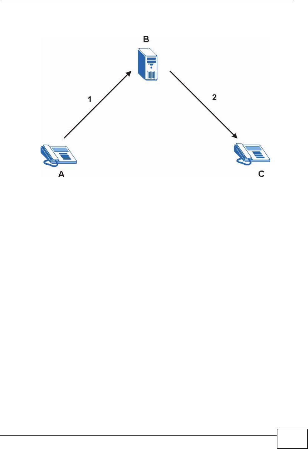
Chapter 10 Voice
P-2612HWU-F1 User’s Guide 205
2The SIP proxy server forwards the call invitation to C.
Figure 130 SIP Proxy Server
SIP Redirect Server
A SIP redirect server accepts SIP requests, translates the destination address to
an IP address and sends the translated IP address back to the device that sent the
request. Then the client device that originally sent the request can send requests
to the IP address that it received back from the redirect server. Redirect servers
do not initiate SIP requests.
In the following example, you want to use client device A to call someone who is
using client device C.
1Client device A sends a call invitation for C to the SIP redirect server (B).
2The SIP redirect server sends the invitation back to A with C’s IP address (or
domain name).
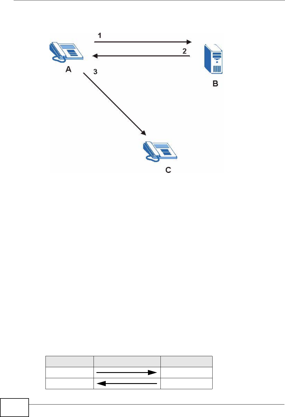
Chapter 10 Voice
P-2612HWU-F1 User’s Guide
206
3Client device A then sends the call invitation to client device C.
Figure 131 SIP Redirect Server
SIP Register Server
A SIP register server maintains a database of SIP identity-to-IP address (or
domain name) mapping. The register server checks your user name and password
when you register.
RTP
When you make a VoIP call using SIP, the RTP (Real time Transport Protocol) is
used to handle voice data transfer. See RFC 1889 for details on RTP.
Pulse Code Modulation
Pulse Code Modulation (PCM) measures analog signal amplitudes at regular time
intervals and converts them into bits.
SIP Call Progression
The following figure displays the basic steps in the setup and tear down of a SIP
call. A calls B.
Table 61 SIP Call Progression
A B
1. INVITE
2. Ringing
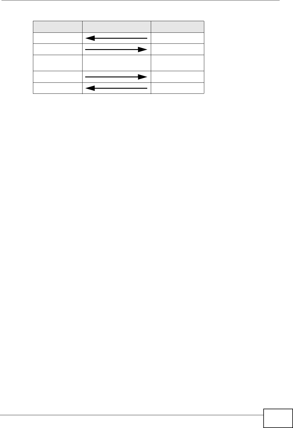
Chapter 10 Voice
P-2612HWU-F1 User’s Guide 207
1A sends a SIP INVITE request to B. This message is an invitation for B to
participate in a SIP telephone call.
2B sends a response indicating that the telephone is ringing.
3B sends an OK response after the call is answered.
4A then sends an ACK message to acknowledge that B has answered the call.
5Now A and B exchange voice media (talk).
6After talking, A hangs up and sends a BYE request.
7B replies with an OK response confirming receipt of the BYE request and the call is
terminated.
SIP Call Progression Through Proxy Servers
Usually, the SIP UAC sets up a phone call by sending a request to the SIP proxy
server. Then, the proxy server looks up the destination to which the call should be
forwarded (according to the URI requested by the SIP UAC). The request may be
forwarded to more than one proxy server before arriving at its destination.
The response to the request goes to all the proxy servers through which the
request passed, in reverse sequence. Once the session is set up, session traffic is
sent between the UAs directly, bypassing all the proxy servers in between.
3. OK
4. ACK
5.Dialogue (voice
traffic)
6. BYE
7. OK
Table 61 SIP Call Progression (continued)
A B
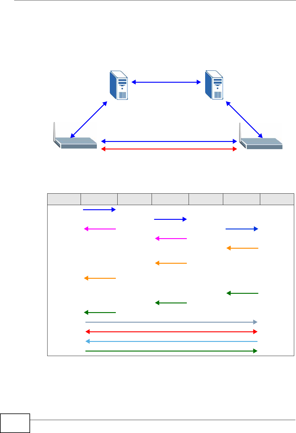
Chapter 10 Voice
P-2612HWU-F1 User’s Guide
208
The following figure shows the SIP and session traffic flow between the user
agents (UA 1 and UA 2) and the proxy servers (this example shows two proxy
servers, PROXY 1 and PROXY 2).
Figure 132 SIP Call Through Proxy Servers
The following table shows the SIP call progression.
1User Agent 1 sends a SIP INVITE request to Proxy 1. This message is an
invitation to User Agent 2 to participate in a SIP telephone call. Proxy 1 sends a
response indicating that it is trying to complete the request.
Table 62 SIP Call Progression
UA 1 PROXY 1 PROXY 2 UA 2
Invite
Invite
100 Trying Invite
100 Trying
180
Ringing
180
Ringing
180
Ringing
200 OK
200 OK
200 OK
ACK
RTP RTP
BYE
200 OK
UA 1 UA 2
PROXY 1 PROXY 2
SIP
SIP
SIP
SIP & RTP

Chapter 10 Voice
P-2612HWU-F1 User’s Guide 209
2Proxy 1 sends a SIP INVITE request to Proxy 2. Proxy 2 sends a response
indicating that it is trying to complete the request.
3Proxy 2 sends a SIP INVITE request to User Agent 2.
4User Agent 2 sends a response back to Proxy 2 indicating that the phone is
ringing. The response is relayed back to User Agent 1 via Proxy 1.
5User Agent 2 sends an OK response to Proxy 2 after the call is answered. This is
also relayed back to User Agent 1 via Proxy 1.
6User Agent 1 and User Agent 2 exchange RTP packets containing voice data
directly, without involving the proxies.
7When User Agent 2 hangs up, he sends a BYE request.
8User Agent 1 replies with an OK response confirming receipt of the BYE request,
and the call is terminated.
Voice Coding
A codec (coder/decoder) codes analog voice signals into digital signals and
decodes the digital signals back into analog voice signals. The ZyXEL Device
supports the following codecs.
• G.711 is a Pulse Code Modulation (PCM) waveform codec. PCM measures analog
signal amplitudes at regular time intervals and converts them into digital
samples. G.711 provides very good sound quality but requires 64 kbps of
bandwidth.
• G.726 is an Adaptive Differential PCM (ADPCM) waveform codec that uses a
lower bitrate than standard PCM conversion. ADPCM converts analog audio into
digital signals based on the difference between each audio sample and a
prediction based on previous samples. The more similar the audio sample is to
the prediction, the less space needed to describe it. G.726 operates at 16, 24,
32 or 40 kbps.
• G.729 is an Analysis-by-Synthesis (AbS) hybrid waveform codec that uses a
filter based on information about how the human vocal tract produces sounds.
G.729 provides good sound quality and reduces the required bandwidth to 8
kbps.
PSTN Call Setup Signaling
Dual-Tone MultiFrequency (DTMF) signaling uses pairs of frequencies (one lower
frequency and one higher frequency) to set up calls. It is also known as Touch
Tone®. Each of the keys on a DTMF telephone corresponds to a different pair of
frequencies.
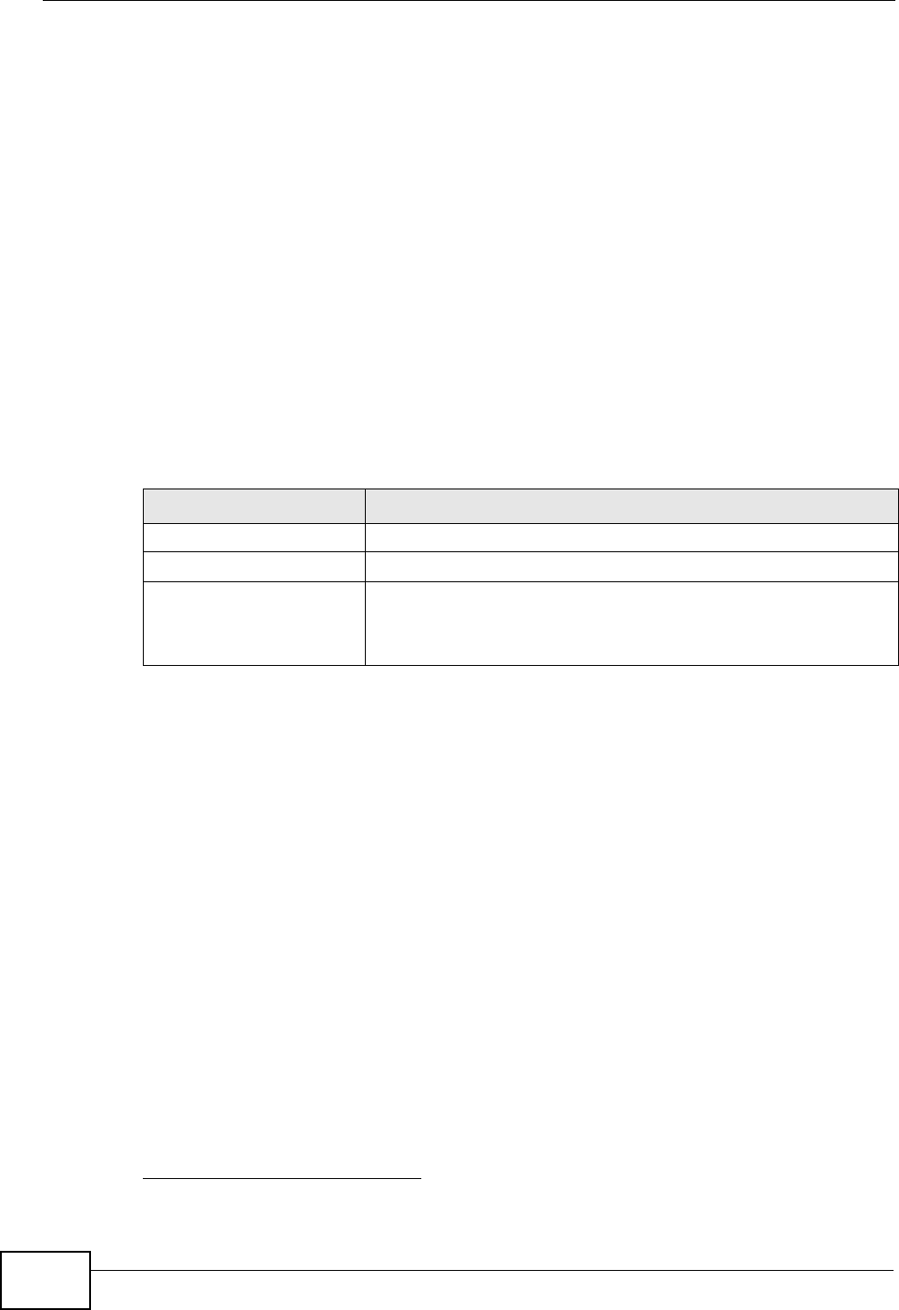
Chapter 10 Voice
P-2612HWU-F1 User’s Guide
210
Pulse dialing sends a series of clicks to the local phone office in order to dial
numbers.3
MWI (Message Waiting Indication)
Enable Message Waiting Indication (MWI) enables your phone to give you a
message–waiting (beeping) dial tone when you have a voice message(s). Your
VoIP service provider must have a messaging system that sends message waiting
status SIP packets as defined in RFC 3842.
Custom Tones (IVR)
IVR (Interactive Voice Response) is a feature that allows you to use your
telephone to interact with the ZyXEL Device. The ZyXEL Device allows you to
record custom tones for the Caller Ringing Tone and On Hold Tone functions.
The same recordings apply to both the caller ringing and on hold tones.
Recording Custom Tones
Use the following steps if you would like to create new tones or change your
tones:
1Pick up the phone and press “****” on your phone’s keypad and wait for the
message that says you are in the configuration menu.
2Press a number from 1101~1108 on your phone followed by the “#” key.
3Play your desired music or voice recording into the receiver’s mouthpiece. Press
the “#” key.
4You can continue to add, listen to, or delete tones, or you can hang up the receiver
when you are done.
Listening to Custom Tones
Do the following to listen to a custom tone:
3. The ZyXEL Device does not support pulse dialing at the time of writing.
Table 63 Custom Tones Details
LABEL DESCRIPTION
Total Time for All Tones 128 seconds for all custom tones combined
Time per Individual Tone 20 seconds
Total Number of Tones
Recordable 8
You can record up to 8 different custom tones but the total
time must be 128 seconds or less.

Chapter 10 Voice
P-2612HWU-F1 User’s Guide 211
1Pick up the phone and press “****” on your phone’s keypad and wait for the
message that says you are in the configuration menu.
2Press a number from 1201~1208 followed by the “#” key to listen to the tone.
3You can continue to add, listen to, or delete tones, or you can hang up the receiver
when you are done.
Deleting Custom Tones
Do the following to delete a custom tone:
1Pick up the phone and press “****” on your phone’s keypad and wait for the
message that says you are in the configuration menu.
2Press a number from 1301~1308 followed by the “#” key to delete the tone of
your choice. Press 14 followed by the “#” key if you wish to clear all your custom
tones.
You can continue to add, listen to, or delete tones, or you can hang up the receiver
when you are done.
10.13.3 Quality of Service (QoS)
Quality of Service (QoS) refers to both a network's ability to deliver data with
minimum delay, and the networking methods used to provide bandwidth for real-
time multimedia applications.
Type of Service (ToS)
Network traffic can be classified by setting the ToS (Type of Service) values at the
data source (for example, at the ZyXEL Device) so a server can decide the best
method of delivery, that is the least cost, fastest route and so on.
DiffServ
DiffServ is a class of service (CoS) model that marks packets so that they receive
specific per-hop treatment at DiffServ-compliant network devices along the route
based on the application types and traffic flow. Packets are marked with DiffServ
Code Points (DSCP) indicating the level of service desired. This allows the
intermediary DiffServ-compliant network devices to handle the packets differently
depending on the code points without the need to negotiate paths or remember
state information for every flow. In addition, applications do not have to request a
particular service or give advanced notice of where the traffic is going.4
4. The ZyXEL Device does not support DiffServ at the time of writing.
Chapter 10 Voice
P-2612HWU-F1 User’s Guide
212
DSCP and Per-Hop Behavior
DiffServ defines a new DS (Differentiated Services) field to replace the Type of
Service (TOS) field in the IP header. The DS field contains a 2-bit unused field and
a 6-bit DSCP field which can define up to 64 service levels. The following figure
illustrates the DS field.
DSCP is backward compatible with the three precedence bits in the ToS octet so
that non-DiffServ compliant, ToS-enabled network device will not conflict with the
DSCP mapping.
Figure 133 DiffServ: Differentiated Service Field
The DSCP value determines the forwarding behavior, the PHB (Per-Hop Behavior),
that each packet gets across the DiffServ network. Based on the marking rule,
different kinds of traffic can be marked for different priorities of forwarding.
Resources can then be allocated according to the DSCP values and the configured
policies.
VLAN Tagging
Virtual Local Area Network (VLAN) allows a physical network to be partitioned into
multiple logical networks. Only stations within the same group can communicate
with each other.
Your ZyXEL Device can add IEEE 802.1Q VLAN ID tags to voice frames that it
sends to the network. This allows the ZyXEL Device to communicate with a SIP
server that is a member of the same VLAN group. Some ISPs use the VLAN tag to
identify voice traffic and give it priority over other traffic.
10.13.4 Phone Services Overview
Supplementary services such as call hold, call waiting, and call transfer. are
generally available from your VoIP service provider. The ZyXEL Device supports
the following services:
• Call Hold
• Call Waiting
• Making a Second Call
• Call Transfer
• Call Forwarding (see Section 10.11 on page 199)
DSCP
(6-bit)
Unused
(2-bit)
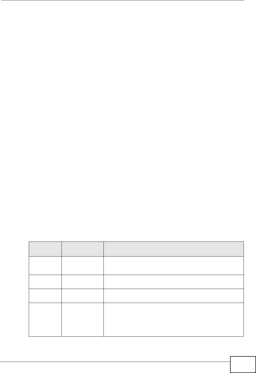
Chapter 10 Voice
P-2612HWU-F1 User’s Guide 213
• Three-Way Conference
•Internal Calls
• Call Park and Pickup
•Do not Disturb
Note: To take full advantage of the supplementary phone services available through
the ZyXEL Device's phone ports, you may need to subscribe to the services
from your VoIP service provider.
The Flash Key
Flashing means to press the hook for a short period of time (a few hundred
milliseconds) before releasing it. On newer telephones, there should be a "flash"
key (button) that generates the signal electronically. If the flash key is not
available, you can tap (press and immediately release) the hook by hand to
achieve the same effect. However, using the flash key is preferred since the timing
is much more precise. With manual tapping, if the duration is too long, it may be
interpreted as hanging up by the ZyXEL Device.
You can invoke all the supplementary services by using the flash key.
Europe Type Supplementary Phone Services
This section describes how to use supplementary phone services with the Europe
Type Call Service Mode. Commands for supplementary services are listed in the
table below.
After pressing the flash key, if you do not issue the sub-command before the
default sub-command timeout (2 seconds) expires or issue an invalid sub-
command, the current operation will be aborted.
Table 64 European Flash Key Commands
COMMAND SUB-
COMMAND DESCRIPTION
Flash Put a current call on hold to place a second call.
Switch back to the call (if there is no second call).
Flash 0 Drop the call presently on hold or reject an incoming call
which is waiting for answer.
Flash 1 Disconnect the current phone connection and answer the
incoming call or resume with caller presently on hold.
Flash 2 1. Switch back and forth between two calls.
2. Put a current call on hold to answer an incoming call.
3. Separate the current three-way conference call into
two individual calls (one is on-line, the other is on hold).
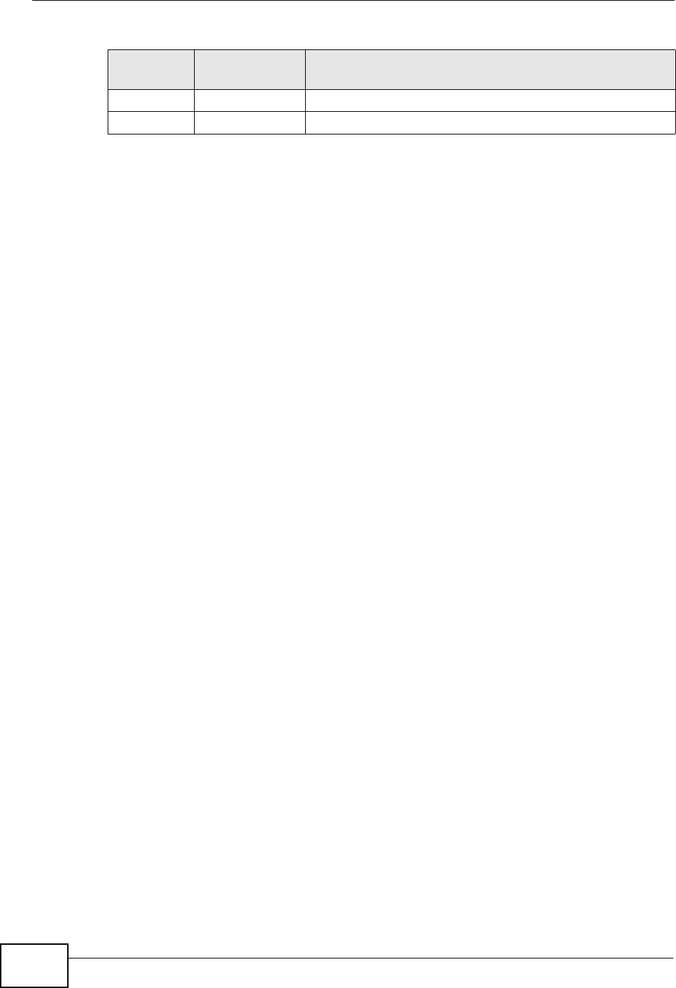
Chapter 10 Voice
P-2612HWU-F1 User’s Guide
214
European Call Hold
Call hold allows you to put a call (A) on hold by pressing the flash key.
If you have another call, press the flash key and then “2” to switch back and forth
between caller A and B by putting either one on hold.
Press the flash key and then “0” to disconnect the call presently on hold and keep
the current call on line.
Press the flash key and then “1” to disconnect the current call and resume the call
on hold.
If you hang up the phone but a caller is still on hold, there will be a remind ring.
European Call Waiting
This allows you to place a call on hold while you answer another incoming call on
the same telephone (directory) number.
If there is a second call to a telephone number, you will hear a call waiting tone.
Take one of the following actions.
• Reject the second call.
Press the flash key and then press “0”.
• Disconnect the first call and answer the second call.
Either press the flash key and press “1”, or just hang up the phone and then
answer the phone after it rings.
• Put the first call on hold and answer the second call.
Press the flash key and then “2”.
European Call Transfer
Do the following to transfer an incoming call (that you have answered) to another
phone.
1Press the flash key to put the caller on hold.
2When you hear the dial tone, dial “*98#” followed by the number to which you
want to transfer the call. to operate the Intercom.
Flash 3 Create three-way conference connection.
Flash *98# Transfer the call to another phone.
Table 64 European Flash Key Commands
COMMAND SUB-
COMMAND DESCRIPTION
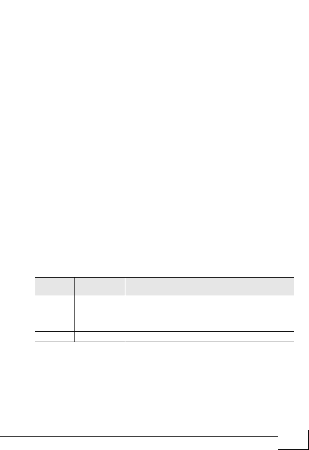
Chapter 10 Voice
P-2612HWU-F1 User’s Guide 215
3After you hear the ring signal or the second party answers it, hang up the phone.
European Three-Way Conference
Use the following steps to make three-way conference calls.
1When you are on the phone talking to someone, press the flash key to put the
caller on hold and get a dial tone.
2Dial a phone number directly to make another call.
3When the second call is answered, press the flash key and press “3” to create a
three-way conversation.
4Hang up the phone to drop the connection.
5If you want to separate the activated three-way conference into two individual
connections (one is on-line, the other is on hold), press the flash key and press
“2”.
USA Type Supplementary Services
This section describes how to use supplementary phone services with the USA
Type Call Service Mode. Commands for supplementary services are listed in the
table below.
After pressing the flash key, if you do not issue the sub-command before the
default sub-command timeout (2 seconds) expires or issue an invalid sub-
command, the current operation will be aborted.
USA Call Hold
Call hold allows you to put a call (A) on hold by pressing the flash key.
If you have another call, press the flash key to switch back and forth between
caller A and B by putting either one on hold.
If you hang up the phone but a caller is still on hold, there will be a remind ring.
Table 65 USA Flash Key Commands
COMMAND SUB-
COMMAND DESCRIPTION
Flash Put a current call on hold to place a second call. After the
second call is successful, press the flash key again to
have a three-way conference call.
Put a current call on hold to answer an incoming call.
Flash *98# Transfer the call to another phone.

Chapter 10 Voice
P-2612HWU-F1 User’s Guide
216
USA Call Waiting
This allows you to place a call on hold while you answer another incoming call on
the same telephone (directory) number.
If there is a second call to your telephone number, you will hear a call waiting
tone.
Press the flash key to put the first call on hold and answer the second call.
USA Call Transfer
Do the following to transfer an incoming call (that you have answered) to another
phone.
1Press the flash key to put the caller on hold.
2When you hear the dial tone, dial “*98#” followed by the number to which you
want to transfer the call. to operate the Intercom.
3After you hear the ring signal or the second party answers it, hang up the phone.
USA Three-Way Conference
Use the following steps to make three-way conference calls.
1When you are on the phone talking to someone (party A), press the flash key to
put the caller on hold and get a dial tone.
2Dial a phone number directly to make another call (to party B).
3When party B answers the second call, press the flash key to create a three-way
conversation.
4Hang up the phone to drop the connection.
5If you want to separate the activated three-way conference into two individual
connections (with party A on-line and party B on hold), press the flash key.
6If you want to go back to the three-way conversation, press the flash key again.
7If you want to separate the activated three-way conference into two individual
connections again, press the flash key. This time the party B is on-line and party A
is on hold.

P-2612HWU-F1 User’s Guide 217
CHAPTER 11
Phone Usage
11.1 Overview
This chapter describes how to use a phone connected to your ZyXEL Device for
basic tasks.
Note: Not all service providers support all features.
11.2 Dialing a Telephone Number
The PHONE LED turns green when your SIP account is registered. Dial a SIP
number like “12345” on your phone’s keypad.
Use speed dial entries (see Section 10.10 on page 196) for peer-to-peer calls or
SIP numbers that use letters. Dial the speed dial entry on your telephone’s
keypad.
Use your VoIP service provider’s dialing plan to call regular telephone numbers.
11.3 Using Speed Dial to Dial a Telephone
Number
After configuring the speed dial entry and adding it to the phonebook, press the
speed dial entry’s key combination on your phone’s keypad.
11.4 Using Call Park and Pickup
Do the following to put a call on hold on one phone and continue it on another
(connected to the ZyXEL Device). This feature may not be supported by all service
providers.

Chapter 11 Phone Usage
P-2612HWU-F1 User’s Guide
218
1During the call, press “*97#” and then any number (up to 8 digits long). You need
to remember this number in order to pick up the call on another phone. Hang up
the receiver.
2Pick up another phone’s receiver. Press “#97#” followed by the same number you
entered before to continue the call.
11.5 Checking the ZyXEL Device’s IP Address
Do the following to listen to the ZyXEL Device’s current IP address.
1Pick up your phone’s receiver.
2Press “****” on your phone’s keypad and wait for the message that says you are
in the configuration menu.
3Press “5” followed by the # key.
4Listen to the IP address and make a note of it.
5Hang up the receiver.
11.6 Auto Provisioning and Auto Firmware
Upgrade
If your service provider uses an auto-provisioning server to set up your device,
you must first enter the HTTP pincode (supplied by your service provider). This
authenticates your ZyXEL Device with the auto provisioning server, allowing you to
use the service.
• On a phone connected to the device, enter “*99**”, your SIP number, “*”, the
HTTP pincode you were given, then “#”.
• For example, if your SIP number is 0123456 and the HTTP pincode you were
given is 9876, you would enter “*99**0123456*9876#”.
During auto-provisioning, the ZyXEL Device checks to see if there is a newer
firmware version (if your service provider activates this feature). If newer
firmware is available, the ZyXEL Device plays a recording when you pick up your
phone’s handset.
• Press “*99#” to upgrade the ZyXEL Device’s firmware.
• Press “#99#” to not upgrade the ZyXEL Device’s firmware.

Chapter 11 Phone Usage
P-2612HWU-F1 User’s Guide 219
11.7 Phone Services Overview
Supplementary services such as call hold, call waiting, and call transfer. are
generally available from your VoIP service provider. The ZyXEL Device supports
the following services:
• Call Hold
• Call Waiting
• Making a Second Call
• Call Transfer
• Call Forwarding (see Section 10.11 on page 199)
• Three-Way Conference
•Internal Calls
• Call Park and Pickup
•Do not Disturb
Note: To take full advantage of the supplementary phone services available through
the ZyXEL Device's phone port, you may need to subscribe to the services from
your VoIP service provider.
11.7.1 The Flash Key
Flashing means to press the hook for a short period of time (a few hundred
milliseconds) before releasing it. On newer telephones, there should be a "flash"
key (button) that generates the signal electronically. If the flash key is not
available, you can tap (press and immediately release) the hook by hand to
achieve the same effect. However, using the flash key is preferred since the timing
is much more precise. With manual tapping, if the duration is too long, it may be
interpreted as hanging up by the ZyXEL Device.
You can invoke all the supplementary services by using the flash key.
11.7.2 Europe Type Supplementary Phone Services
This section describes how to use supplementary phone services with the Europe
Type Call Service Mode. Commands for supplementary services are listed in the
table below.
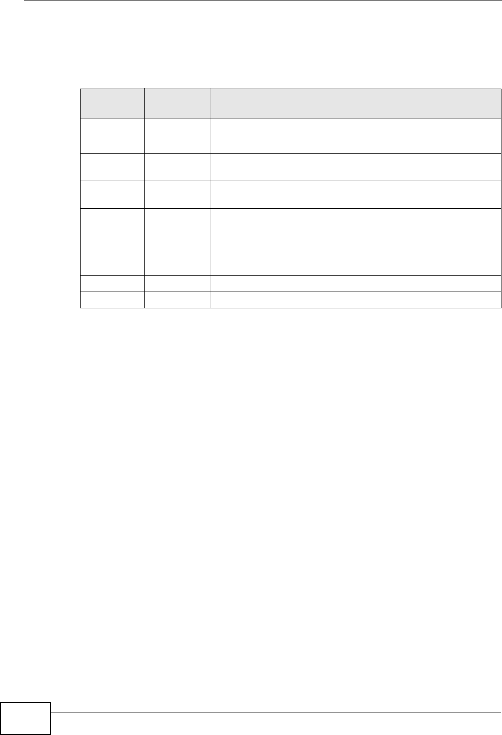
Chapter 11 Phone Usage
P-2612HWU-F1 User’s Guide
220
After pressing the flash key, if you do not issue the sub-command before the
default sub-command timeout (2 seconds) expires or issue an invalid sub-
command, the current operation will be aborted.
11.7.2.1 European Call Hold
Call hold allows you to put a call (A) on hold by pressing the flash key.
If you have another call, press the flash key and then “2” to switch back and forth
between caller A and B by putting either one on hold.
Press the flash key and then “0” to disconnect the call presently on hold and keep
the current call on line.
Press the flash key and then “1” to disconnect the current call and resume the call
on hold.
If you hang up the phone but a caller is still on hold, there will be a remind ring.
11.7.2.2 European Call Waiting
This allows you to place a call on hold while you answer another incoming call on
the same telephone (directory) number.
If there is a second call to a telephone number, you will hear a call waiting tone.
Take one of the following actions.
• Reject the second call.
Press the flash key and then press “0”.
Table 66 European Flash Key Commands
COMMAND SUB-
COMMAND DESCRIPTION
Flash Put a current call on hold to place a second call.
Switch back to the call (if there is no second call).
Flash 0 Drop the call presently on hold or reject an incoming call
which is waiting for answer.
Flash 1 Disconnect the current phone connection and answer the
incoming call or resume with caller presently on hold.
Flash 2 1. Switch back and forth between two calls.
2. Put a current call on hold to answer an incoming call.
3. Separate the current three-way conference call into two
individual calls (one is on-line, the other is on hold).
Flash 3 Create three-way conference connection.
Flash *98# Transfer the call to another phone.

Chapter 11 Phone Usage
P-2612HWU-F1 User’s Guide 221
• Disconnect the first call and answer the second call.
Either press the flash key and press “1”, or just hang up the phone and then
answer the phone after it rings.
• Put the first call on hold and answer the second call.
Press the flash key and then “2”.
11.7.2.3 European Call Transfer
Do the following to transfer an incoming call (that you have answered) to another
phone.
1Press the flash key to put the caller on hold.
2When you hear the dial tone, dial “*98#” followed by the number to which you
want to transfer the call. to operate the Intercom.
3After you hear the ring signal or the second party answers it, hang up the phone.
11.7.2.4 European Three-Way Conference
Use the following steps to make three-way conference calls.
1When you are on the phone talking to someone, press the flash key to put the
caller on hold and get a dial tone.
2Dial a phone number directly to make another call.
3When the second call is answered, press the flash key and press “3” to create a
three-way conversation.
4Hang up the phone to drop the connection.
5If you want to separate the activated three-way conference into two individual
connections (one is on-line, the other is on hold), press the flash key and press
“2”.
11.7.3 USA Type Supplementary Services
This section describes how to use supplementary phone services with the USA
Type Call Service Mode. Commands for supplementary services are listed in the
table below.
Chapter 11 Phone Usage
P-2612HWU-F1 User’s Guide
222
After pressing the flash key, if you do not issue the sub-command before the
default sub-command timeout (2 seconds) expires or issue an invalid sub-
command, the current operation will be aborted.
11.7.3.1 USA Call Hold
Call hold allows you to put a call (A) on hold by pressing the flash key.
If you have another call, press the flash key to switch back and forth between
caller A and B by putting either one on hold.
If you hang up the phone but a caller is still on hold, there will be a remind ring.
11.7.3.2 USA Call Waiting
This allows you to place a call on hold while you answer another incoming call on
the same telephone (directory) number.
If there is a second call to your telephone number, you will hear a call waiting
tone.
Press the flash key to put the first call on hold and answer the second call.
11.7.3.3 USA Call Transfer
Do the following to transfer an incoming call (that you have answered) to another
phone.
1Press the flash key to put the caller on hold.
2When you hear the dial tone, dial “*98#” followed by the number to which you
want to transfer the call. to operate the Intercom.
3After you hear the ring signal or the second party answers it, hang up the phone.
11.7.3.4 USA Three-Way Conference
Use the following steps to make three-way conference calls.
Table 67 USA Flash Key Commands
COMMAND SUB-
COMMAND DESCRIPTION
Flash Put a current call on hold to place a second call. After the
second call is successful, press the flash key again to have a
three-way conference call.
Put a current call on hold to answer an incoming call.
Flash *98# Transfer the call to another phone.
Chapter 11 Phone Usage
P-2612HWU-F1 User’s Guide 223
1When you are on the phone talking to someone (party A), press the flash key to
put the caller on hold and get a dial tone.
2Dial a phone number directly to make another call (to party B).
3When party B answers the second call, press the flash key to create a three-way
conversation.
4Hang up the phone to drop the connection.
5If you want to separate the activated three-way conference into two individual
connections (with party A on-line and party B on hold), press the flash key.
6If you want to go back to the three-way conversation, press the flash key again.
7If you want to separate the activated three-way conference into two individual
connections again, press the flash key. This time the party B is on-line and party A
is on hold.
11.8 Phone Functions Summary
The following table shows the key combinations you can enter on your phone’s
keypad to use certain features.
Table 68 Phone Functions Summary
ACTION FUNCTION DESCRIPTION
*99** HTTP pincode Use this if your service provider gave you a personal
identification number to enter in order to start using
the service. See Section 11.6 on page 218.
*99# Enable firmware update Use these to upload or not upload new firmware to
the ZyXEL Device, if requested by your service
provider. See Section 11.6 on page 218.
#99# Disable firmware update
*98# Call transfer Transfer a call to another phone. See Section 11.7.2
on page 219 (Europe type) and Section 11.7.3 on
page 221 (USA type).
*97# Call park Use these to place a call on hold on one phone and
then continue it on another (if supported by your
service provider). See Chapter 30 on page 471.
#97# Call pickup
*66# Call return Place a call to the last person who called you. See
Chapter 30 on page 471.
*95# Enable Do Not Disturb Use these to set your phone not to ring when
someone calls you, or to turn this function off.
Chapter 30 on page 471
#95# Disable Do Not Disturb
*41# Enable call waiting Use these to allow you to put a call on hold while
answering another, or to turn this function off. See
Section 11.7.2 on page 219 (Europe type) and
Section 11.7.3 on page 221 (USA type).
#41# Disable call waiting
Chapter 11 Phone Usage
P-2612HWU-F1 User’s Guide
224
*21# Enable call forward Use these to allow you to use the call forwarding
tables you set in the ZyXEL Device, or to turn this
function off. See Section 10.11 on page 199.
#21# Disable call forward
*22* Uncondition forward Forward all incoming calls. See Section 10.11 on
page 199.
*23* No answer forward Forward incoming calls if you do not answer. See
Section 10.11 on page 199.
*24* Busy forward Forward calls if you are already making a call. See
Section 10.11 on page 199.
*70 One shot Call Waiting
Disable Activate or deactivate call waiting on the next call
only. See Section 11.7.2 on page 219 (Europe type)
and Section 11.7.3 on page 221 (USA type)
*85 One shot Call Waiting
Enable
Table 68 Phone Functions Summary
ACTION FUNCTION DESCRIPTION
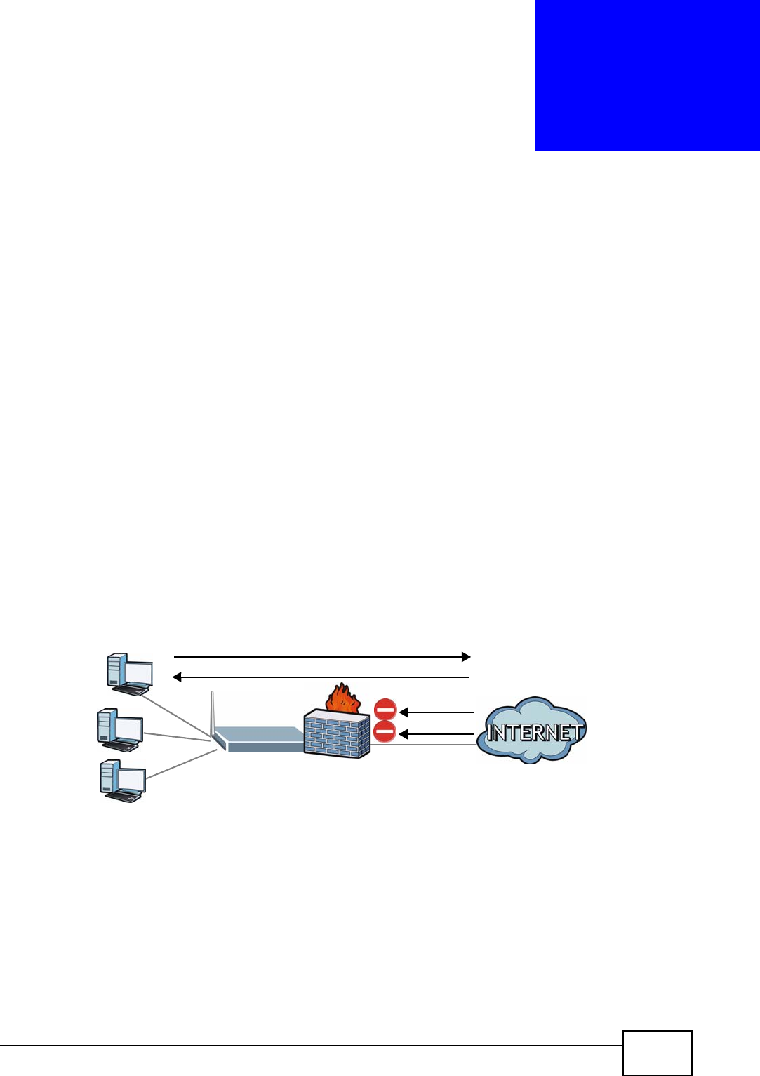
P-2612HWU-F1 User’s Guide 225
CHAPTER 12
Firewall
12.1 Overview
Use the ZyXEL Device firewall screens to enable and configure the firewall that
protects your ZyXEL Device and network from attacks by hackers on the Internet
and control access to it. By default the firewall:
• allows traffic that originates from your LAN computers to go to all other
networks.
• blocks traffic that originates on other networks from going to the LAN.
The following figure illustrates the default firewall action. User A can initiate an IM
(Instant Messaging) session from the LAN to the WAN (1). Return traffic for this
session is also allowed (2). However other traffic initiated from the WAN is blocked
(3 and 4).
Figure 134 Default Firewall Action
12.1.1 What You Can Do in the Firewall Screens
•Use the General screen (Section 12.2 on page 230) to enable firewall and/or
triangle route on the ZyXEL Device, and set the default action that the firewall
takes on packets that do not match any of the firewall rules.
•Use the Rules screen (Section 12.3 on page 232) to view the configured firewall
rules and add, edit or remove a firewall rule.
WAN
LAN
3
4
1
2
A

Chapter 12 Firewall
P-2612HWU-F1 User’s Guide
226
•Use the Threshold screen (Section 12.4 on page 237) to set the thresholds that
the ZyXEL Device uses to determine when to start dropping sessions that do not
become fully established (half-open sessions).
12.1.2 What You Need to Know About Firewall
DoS
Denials of Service (DoS) attacks are aimed at devices and networks with a
connection to the Internet. Their goal is not to steal information, but to disable a
device or network so users no longer have access to network resources. The
ZyXEL Device is pre-configured to automatically detect and thwart all known DoS
attacks.
Anti-Probing
If an outside user attempts to probe an unsupported port on your ZyXEL Device,
an ICMP response packet is automatically returned. This allows the outside user to
know the ZyXEL Device exists. The ZyXEL Device supports anti-probing, which
prevents the ICMP response packet from being sent. This keeps outsiders from
discovering your ZyXEL Device when unsupported ports are probed.
ICMP
Internet Control Message Protocol (ICMP) is a message control and error-reporting
protocol between a host server and a gateway to the Internet. ICMP uses Internet
Protocol (IP) datagrams, but the messages are processed by the TCP/IP software
and directly apparent to the application user.
DoS Thresholds
For DoS attacks, the ZyXEL Device uses thresholds to determine when to drop
sessions that do not become fully established. These thresholds apply globally to
all sessions. You can use the default threshold values, or you can change them to
values more suitable to your security requirements.
Finding Out More
• See Section 12.1.3 on page 226 for an example of setting up a firewall.
• See Section 12.5 on page 241 for advanced technical information on firewall.
12.1.3 Firewall Rule Setup Example
The following Internet firewall rule example allows a hypothetical “MyService”
connection from the Internet.
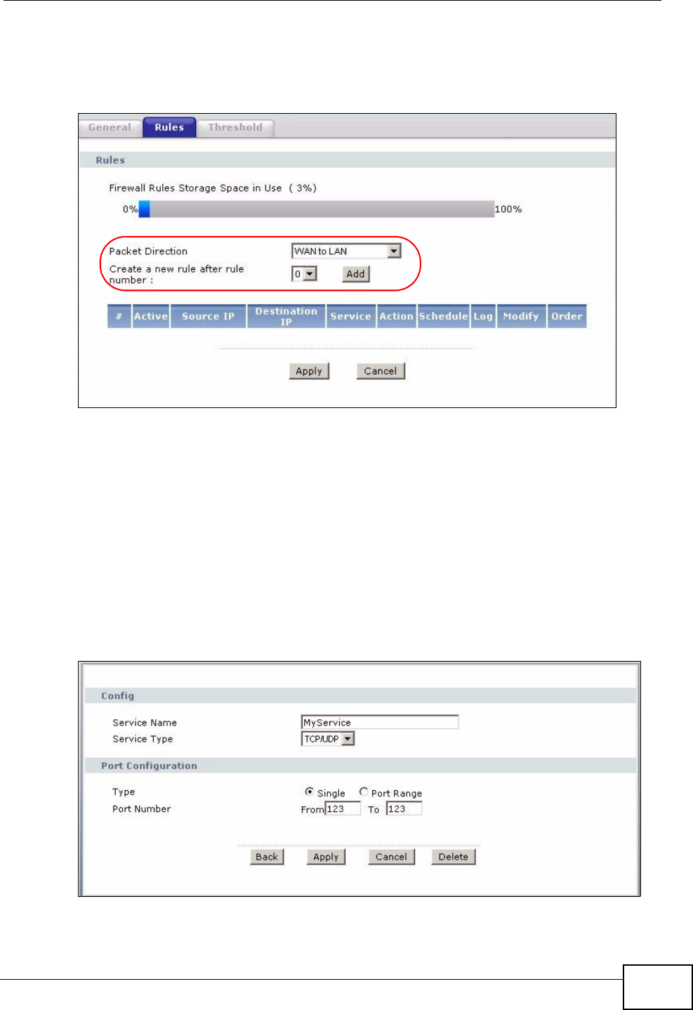
Chapter 12 Firewall
P-2612HWU-F1 User’s Guide 227
1Click Security > Firewall > Rules.
2Select WAN to LAN in the Packet Direction field.
Figure 135 Firewall Example: Rules
3In the Rules screen, select the index number after that you want to add the rule.
For example, if you select “6”, your new rule becomes number 7 and the previous
rule 7 (if there is one) becomes rule 8.
4Click Add to display the firewall rule configuration screen.
5In the Edit Rule screen, click the Edit Customized Services link to open the
Customized Service screen.
6Click an index number to display the Customized Services Config screen and
configure the screen as follows and click Apply.
Figure 136 Edit Custom Port Example
7Select Any in the Destination Address List box and then click Delete.
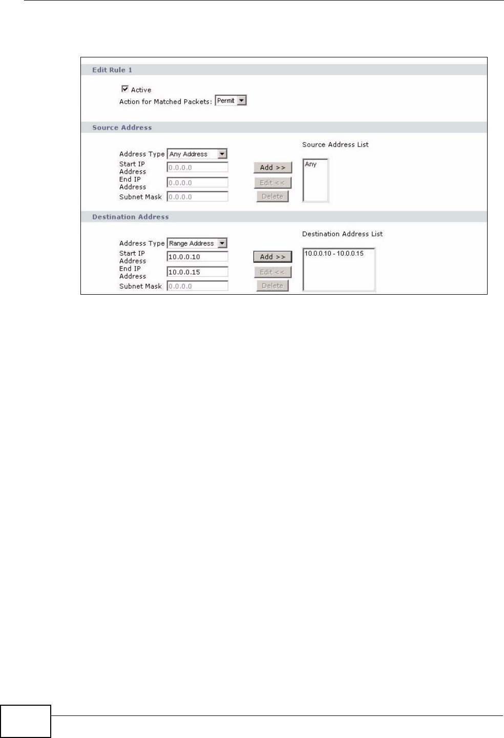
Chapter 12 Firewall
P-2612HWU-F1 User’s Guide
228
8Configure the destination address screen as follows and click Add.
Figure 137 Firewall Example: Edit Rule: Destination Address
9Use the Add >> and Remove buttons between Available Services and
Selected Services list boxes to configure it as follows. Click Apply when you are
done.
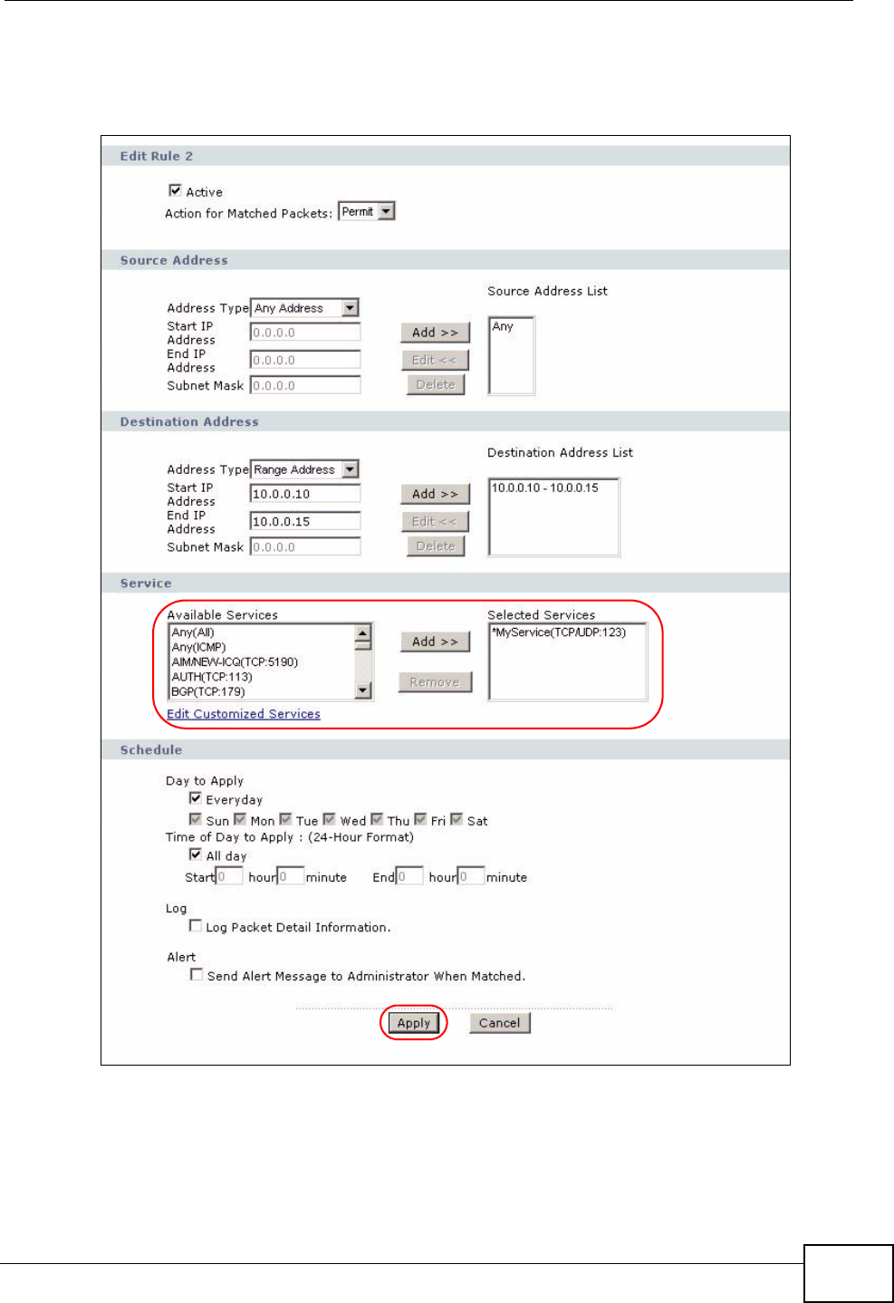
Chapter 12 Firewall
P-2612HWU-F1 User’s Guide 229
Note: Custom services show up with an “*” before their names in the Services list box
and the Rules list box.
Figure 138 Firewall Example: Edit Rule: Select Customized Services
On completing the configuration procedure for this Internet firewall rule, the
Rules screen should look like the following.
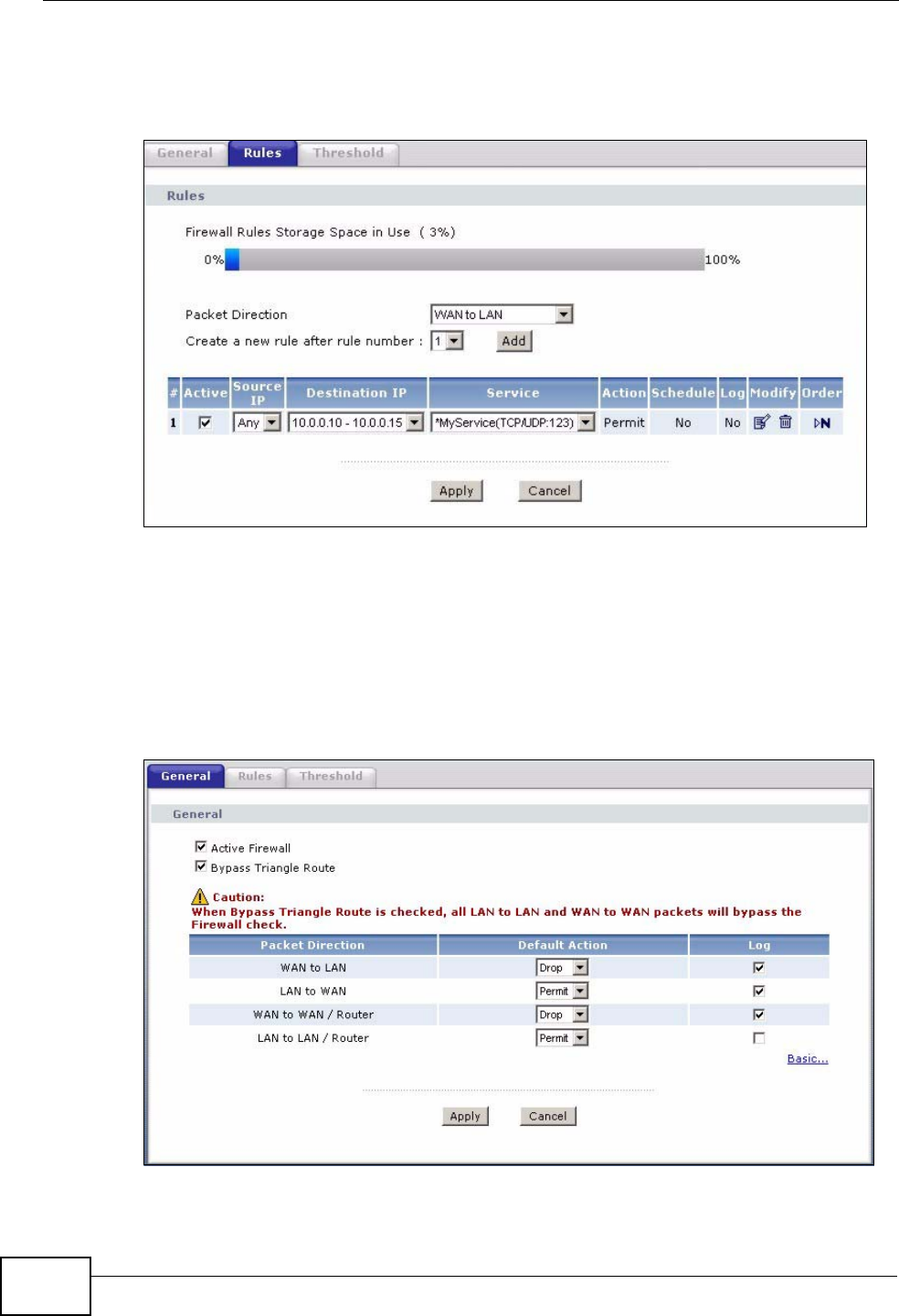
Chapter 12 Firewall
P-2612HWU-F1 User’s Guide
230
Rule 1 allows a “MyService” connection from the WAN to IP addresses 10.0.0.10
through 10.0.0.15 on the LAN.
Figure 139 Firewall Example: Rules: MyService
12.2 The Firewall General Screen
Use this screen to configure the firewall settings. Click Security > Firewall to
display the following screen.
Figure 140 Security > Firewall > General
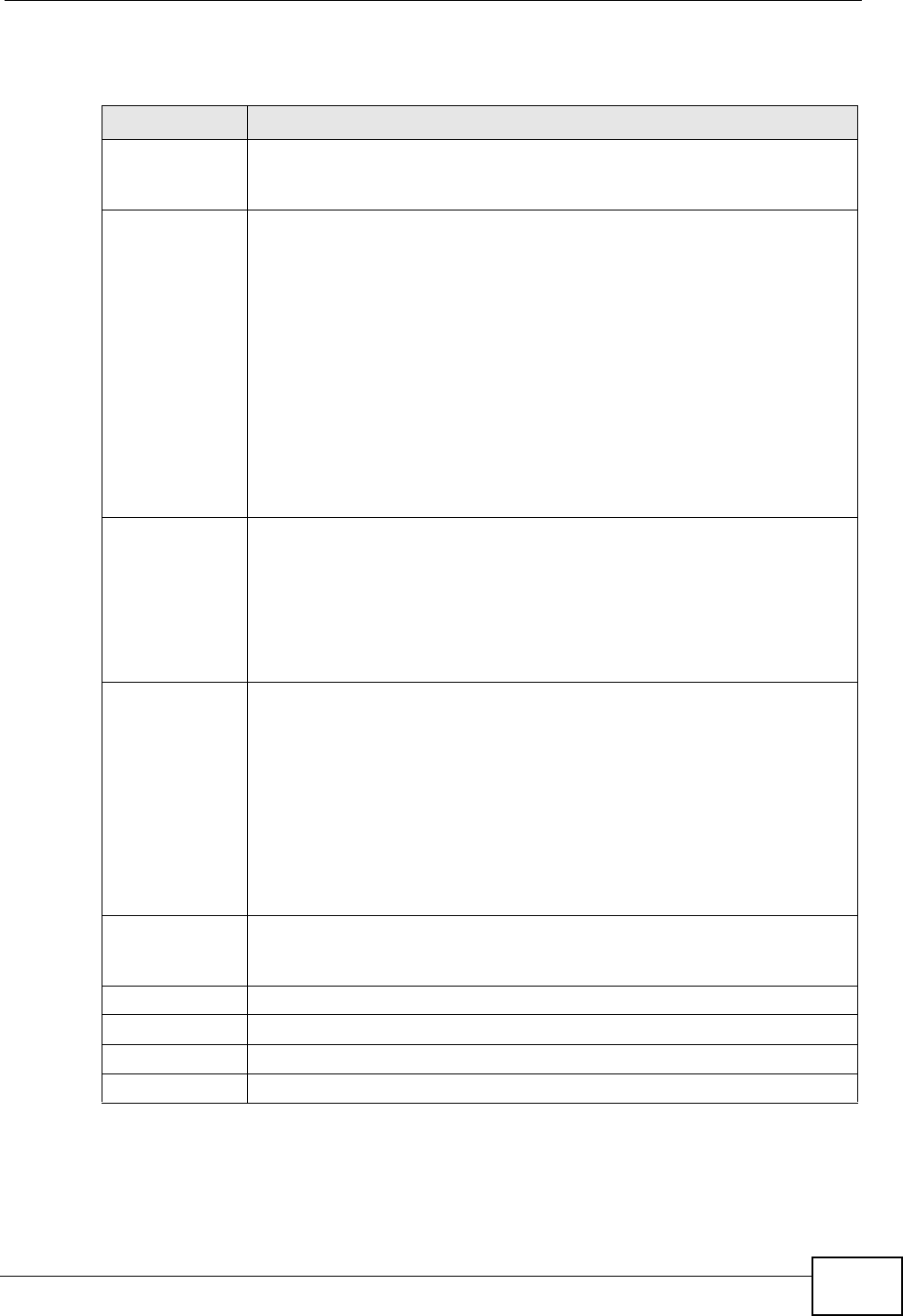
Chapter 12 Firewall
P-2612HWU-F1 User’s Guide 231
The following table describes the labels in this screen.
Table 69 Security > Firewall > General
LABEL DESCRIPTION
Active Firewall Select this check box to activate the firewall. The ZyXEL Device
performs access control and protects against Denial of Service (DoS)
attacks when the firewall is activated.
Bypass Triangle
Route If an alternate gateway on the LAN has an IP address in the same
subnet as the ZyXEL Device’s LAN IP address, return traffic may not go
through the ZyXEL Device. This is called an asymmetrical or “triangle”
route. This causes the ZyXEL Device to reset the connection, as the
connection has not been acknowledged.
Select this check box to have the ZyXEL Device permit the use of
asymmetrical route topology on the network (not reset the connection).
Note: Allowing asymmetrical routes may let traffic from the WAN go
directly to the LAN without passing through the ZyXEL
Device. A better solution is to use IP alias to put the ZyXEL
Device and the backup gateway on separate subnets. See
Section 12.5.4.1 on page 243 for an example.
Packet
Direction This is the direction of travel of packets (LAN to LAN / Router, LAN to
WAN, WAN to WAN / Router, WAN to LAN).
Firewall rules are grouped based on the direction of travel of packets to
which they apply. For example, LAN to LAN / Router means packets
traveling from a computer/subnet on the LAN to either another
computer/subnet on the LAN interface of the ZyXEL Device or the ZyXEL
Device itself.
Default Action Use the drop-down list boxes to select the default action that the
firewall is to take on packets that are traveling in the selected direction
and do not match any of the firewall rules.
Select Drop to silently discard the packets without sending a TCP reset
packet or an ICMP destination-unreachable message to the sender.
Select Reject to deny the packets and send a TCP reset packet (for a
TCP packet) or an ICMP destination-unreachable message (for a UDP
packet) to the sender.
Select Permit to allow the passage of the packets.
Log Select the check box to create a log (when the above action is taken)
for packets that are traveling in the selected direction and do not match
any of your customized rules.
Expand... Click this to display more information.
Basic... Click this to display less information.
Apply Click this to save your changes.
Cancel Click this to restore your previously saved settings.
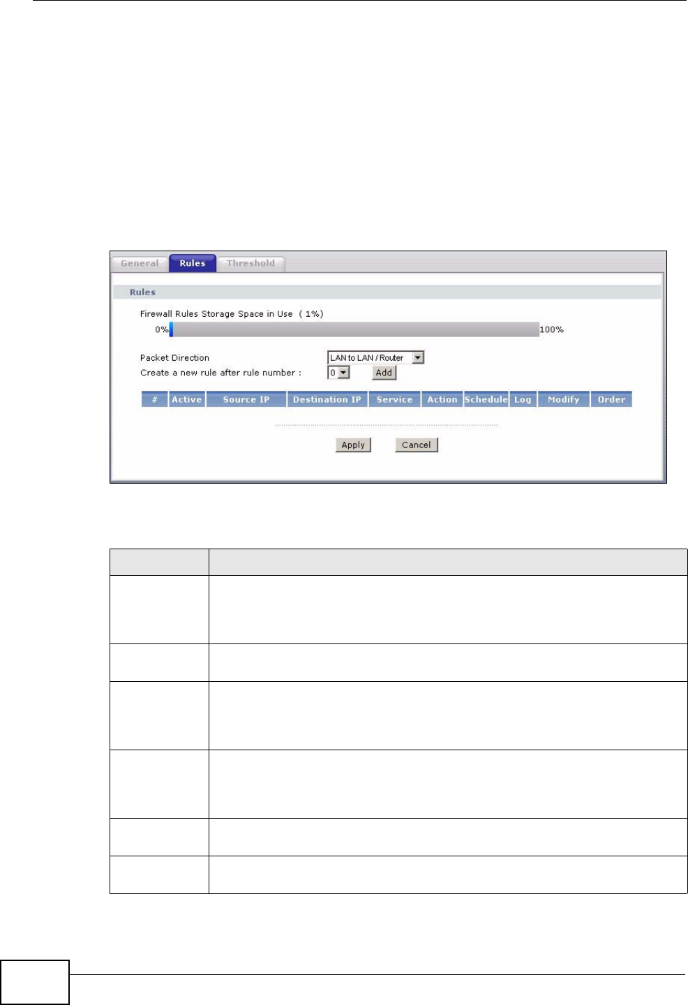
Chapter 12 Firewall
P-2612HWU-F1 User’s Guide
232
12.3 The Firewall Rule Screen
Note: The ordering of your rules is very important as rules are applied in turn.
Refer to Section 12.5 on page 241 for more information.
Click Security > Firewall > Rules to bring up the following screen. This screen
displays a list of the configured firewall rules. Note the order in which the rules are
listed.
Figure 141 Security > Firewall > Rules
The following table describes the labels in this screen.
Table 70 Security > Firewall > Rules
LABEL DESCRIPTION
Firewall Rules
Storage
Space in Use
This read-only bar shows how much of the ZyXEL Device's memory for
recording firewall rules it is currently using. When you are using 80% or
less of the storage space, the bar is green. When the amount of space
used is over 80%, the bar is red.
Packet
Direction Use the drop-down list box to select a direction of travel of packets for
which you want to configure firewall rules.
Create a new
rule after rule
number
Select an index number and click Add to add a new firewall rule after the
selected index number. For example, if you select “6”, your new rule
becomes number 7 and the previous rule 7 (if there is one) becomes rule
8.
The following read-only fields summarize the rules you have created that
apply to traffic traveling in the selected packet direction. The firewall rules
that you configure (summarized below) take priority over the general
firewall action settings in the General screen.
#This is your firewall rule number. The ordering of your rules is important
as rules are applied in turn.
Active This field displays whether a firewall is turned on or not. Select the check
box to enable the rule. Clear the check box to disable the rule.
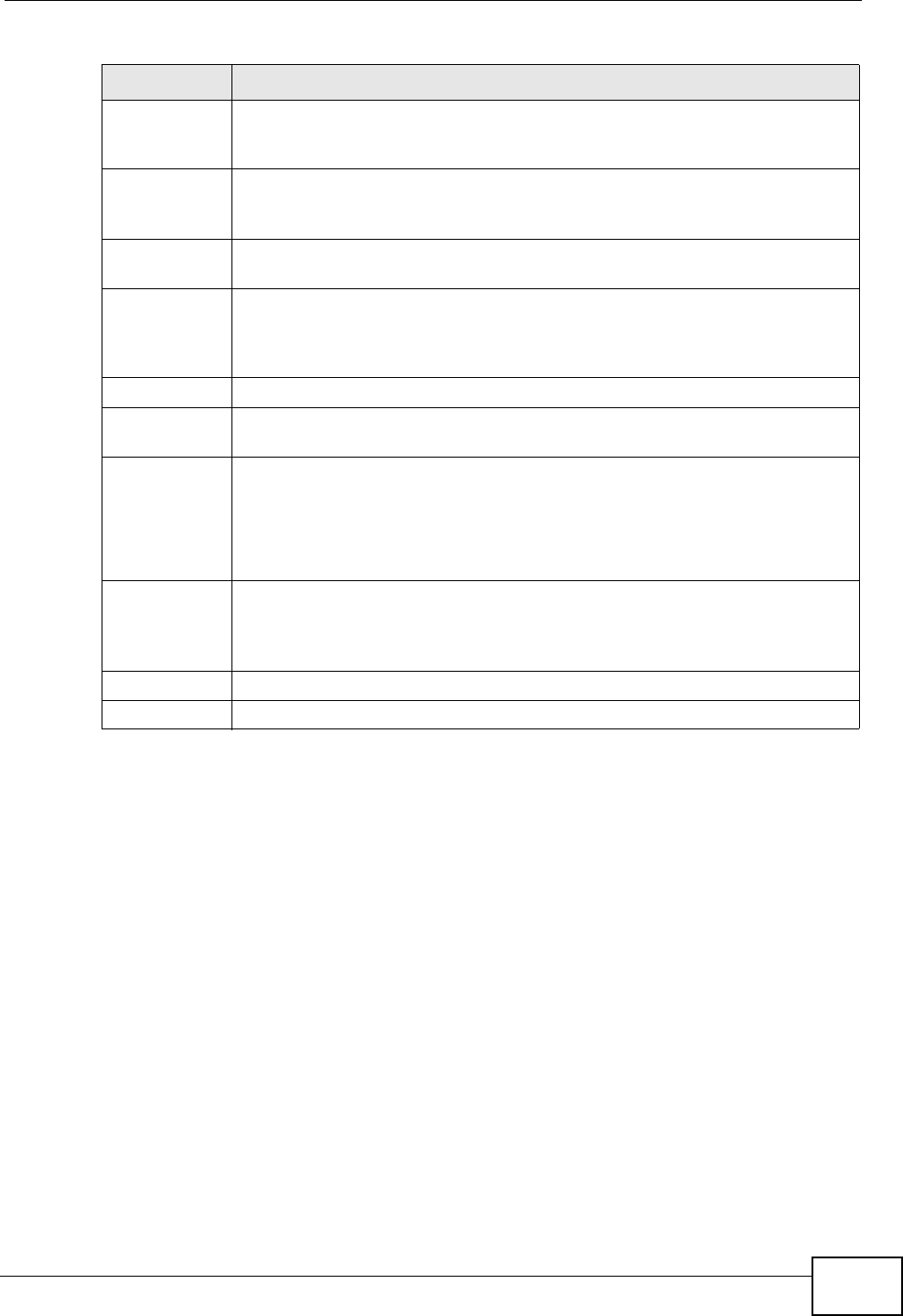
Chapter 12 Firewall
P-2612HWU-F1 User’s Guide 233
12.3.1 Configuring Firewall Rules
Refer to Section 12.1.2 on page 226 for more information.
Source IP This drop-down list box displays the source addresses or ranges of
addresses to which this firewall rule applies. Please note that a blank
source or destination address is equivalent to Any.
Destination IP This drop-down list box displays the destination addresses or ranges of
addresses to which this firewall rule applies. Please note that a blank
source or destination address is equivalent to Any.
Service This drop-down list box displays the services to which this firewall rule
applies. See Appendix E on page 557 for more information.
Action This field displays whether the firewall silently discards packets (Drop),
discards packets and sends a TCP reset packet or an ICMP destination-
unreachable message to the sender (Reject) or allows the passage of
packets (Permit).
Schedule This field tells you whether a schedule is specified (Yes) or not (No).
Log This field shows you whether a log is created when packets match this
rule (Yes) or not (No).
Modify Click the Edit icon to go to the screen where you can edit the rule.
Click the Remove icon to delete an existing firewall rule. A window
displays asking you to confirm that you want to delete the firewall rule.
Note that subsequent firewall rules move up by one when you take this
action.
Order Click the Move icon to display the Move the rule to field. Type a number
in the Move the rule to field and click the Move button to move the rule
to the number that you typed. The ordering of your rules is important as
they are applied in order of their numbering.
Apply Click this to save your changes.
Cancel Click this to restore your previously saved settings.
Table 70 Security > Firewall > Rules (continued)
LABEL DESCRIPTION
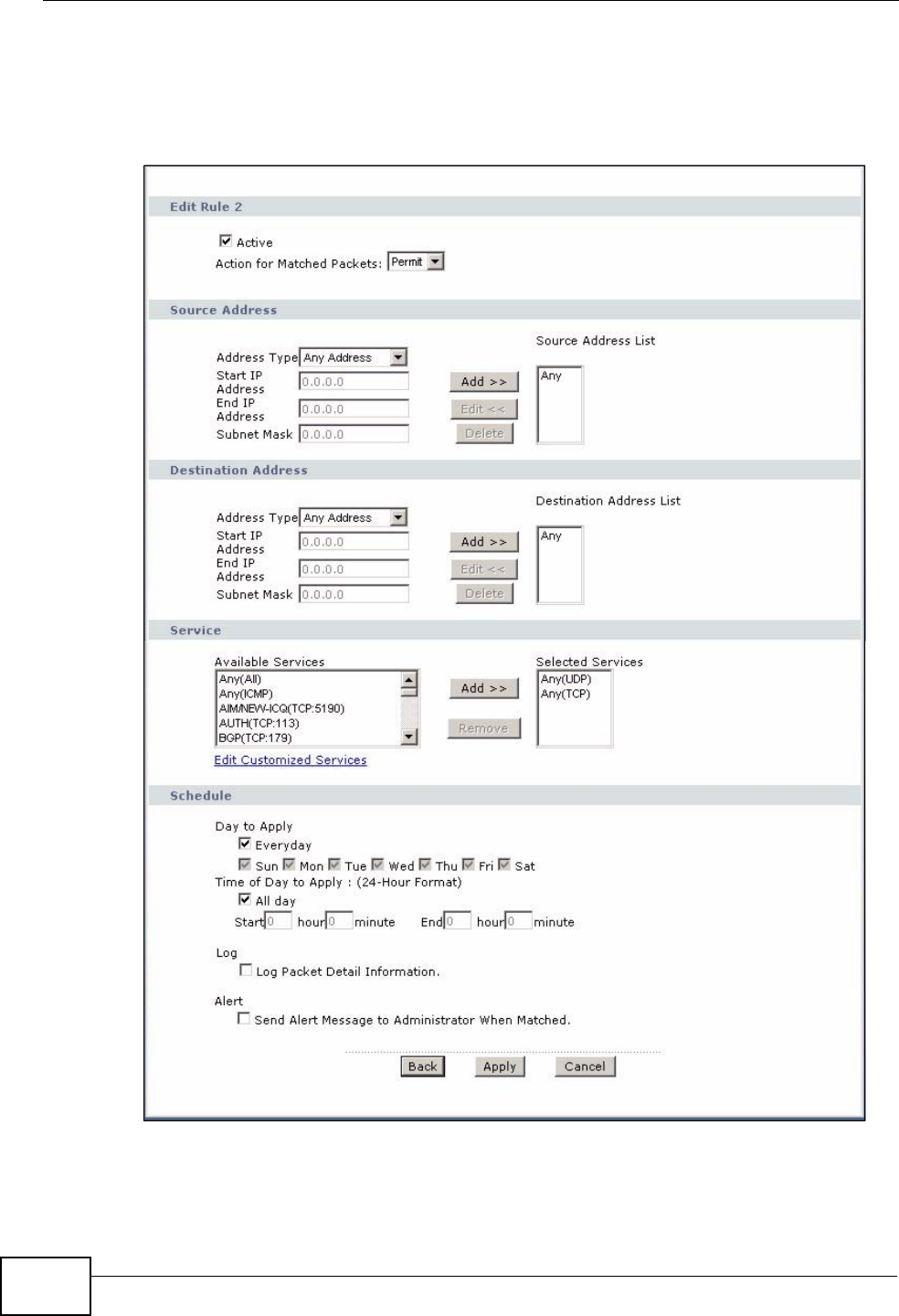
Chapter 12 Firewall
P-2612HWU-F1 User’s Guide
234
Use this screen to configure firewall rules. In the Rules screen, select an index
number and click Add or click a rule’s Edit icon to display this screen and refer to
the following table for information on the labels.
Figure 142 Security > Firewall > Rules > Edit

Chapter 12 Firewall
P-2612HWU-F1 User’s Guide 235
The following table describes the labels in this screen.
Table 71 Security > Firewall > Rules: Edit
LABEL DESCRIPTION
Edit Rule
Active Select this option to enable this firewall rule.
Action for
Matched Packet Use the drop-down list box to select whether to discard (Drop), deny
and send an ICMP destination-unreachable message to the sender of
(Reject) or allow the passage of (Permit) packets that match this
rule.
Source/Destination Address
Address Type Do you want your rule to apply to packets with a particular (single) IP,
a range of IP addresses (for instance, 192.168.1.10 to 192.169.1.50),
a subnet or any IP address? Select an option from the drop-down list
box that includes: Single Address, Range Address, Subnet
Address and Any Address.
Start IP Address Enter the single IP address or the starting IP address in a range here.
End IP Address Enter the ending IP address in a range here.
Subnet Mask Enter the subnet mask here, if applicable.
Add >> Click Add >> to add a new address to the Source or Destination
Address box. You can add multiple addresses, ranges of addresses,
and/or subnets.
Edit << To edit an existing source or destination address, select it from the box
and click Edit <<.
Delete Highlight an existing source or destination address from the Source or
Destination Address box above and click Delete to remove it.
Services
Available/
Selected Services Please see Appendix E on page 557 for more information on services
available. Highlight a service from the Available Services box on the
left, then click Add >> to add it to the Selected Services box on the
right. To remove a service, highlight it in the Selected Services box
on the right, then click Remove.
Edit Customized
Service Click the Edit Customized Services link to bring up the screen that
you use to configure a new custom service that is not in the predefined
list of services.
Schedule
Day to Apply Select everyday or the day(s) of the week to apply the rule.
Time of Day to
Apply (24-Hour
Format)
Select All Day or enter the start and end times in the hour-minute
format to apply the rule.
Log
Log Packet Detail
Information This field determines if a log for packets that match the rule is created
or not. Go to the Log Settings page and select the Access Control
logs category to have the ZyXEL Device record these logs.
Alert
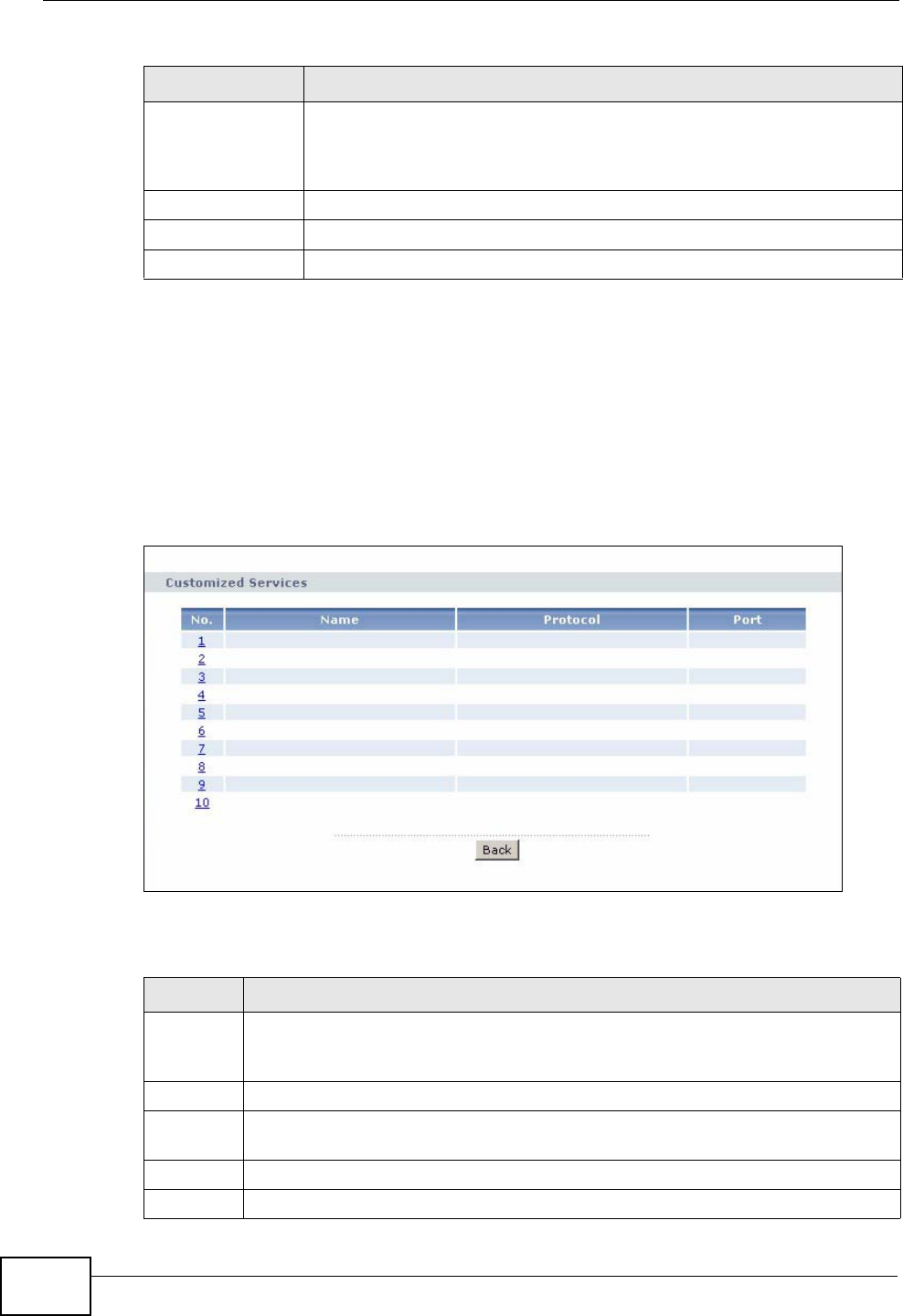
Chapter 12 Firewall
P-2612HWU-F1 User’s Guide
236
12.3.2 Customized Services
Configure customized services and port numbers not predefined by the ZyXEL
Device. For a comprehensive list of port numbers and services, visit the IANA
(Internet Assigned Number Authority) website. See Appendix E on page 557 for
some examples. Click the Edit Customized Services link while editing a firewall
rule to configure a custom service port. This displays the following screen.
Figure 143 Security > Firewall > Rules: Edit: Edit Customized Services
The following table describes the labels in this screen.
Send Alert
Message to
Administrator
When Matched
Select the check box to have the ZyXEL Device generate an alert when
the rule is matched.
Back Click this to return to the previous screen without saving.
Apply Click this to save your changes.
Cancel Click this to restore your previously saved settings.
Table 71 Security > Firewall > Rules: Edit (continued)
LABEL DESCRIPTION
Table 72 Security > Firewall > Rules: Edit: Edit Customized Services
LABEL DESCRIPTION
No. This is the number of your customized port. Click a rule’s number of a service
to go to the Firewall Customized Services Config screen to configure or
edit a customized service.
Name This is the name of your customized service.
Protocol This shows the IP protocol (TCP, UDP or TCP/UDP) that defines your
customized service.
Port This is the port number or range that defines your customized service.
Back Click this to return to the Firewall Edit Rule screen.
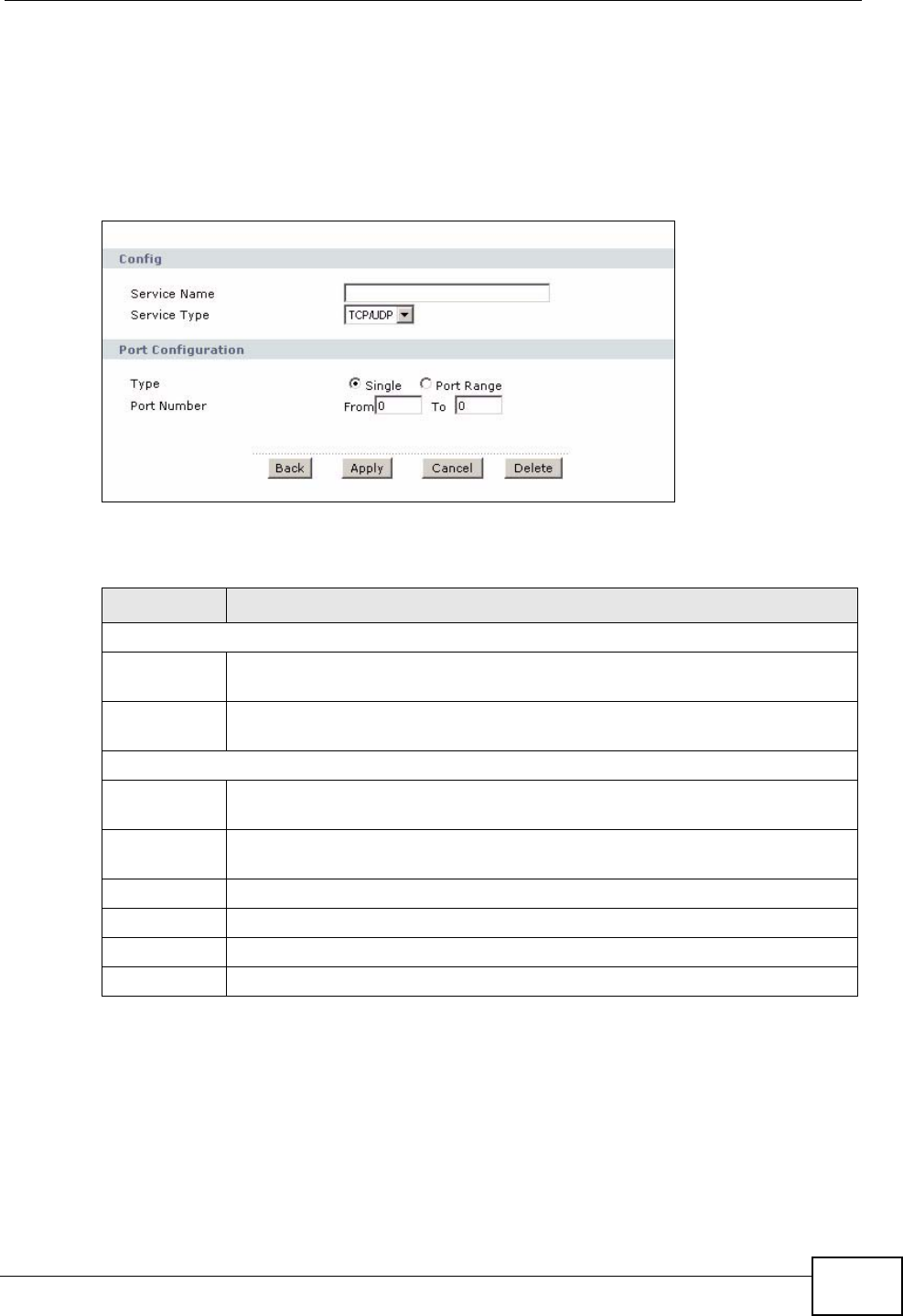
Chapter 12 Firewall
P-2612HWU-F1 User’s Guide 237
12.3.3 Configuring a Customized Service
Use this screen to add a customized rule or edit an existing rule. Click a rule
number in the Firewall Customized Services screen to display the following
screen.
Figure 144 Security > Firewall > Rules: Edit: Edit Customized Services: Config
The following table describes the labels in this screen.
12.4 The Firewall Threshold Screen
For DoS attacks, the ZyXEL Device uses thresholds to determine when to start
dropping sessions that do not become fully established (half-open sessions).
These thresholds apply globally to all sessions.
Table 73 Security > Firewall > Rules: Edit: Edit Customized Services: Config
LABEL DESCRIPTION
Config
Service
Name Type a unique name for your custom port.
Service Type Choose the IP port (TCP, UDP or TCP/UDP) that defines your customized
port from the drop down list box.
Port Configuration
Type Click Single to specify one port only or Range to specify a span of ports
that define your customized service.
Port Number Type a single port number or the range of port numbers that define your
customized service.
Back Click this to return to the previous screen without saving.
Apply Click this to save your changes.
Cancel Click this to restore your previously saved settings.
Delete Click this to delete the current rule.
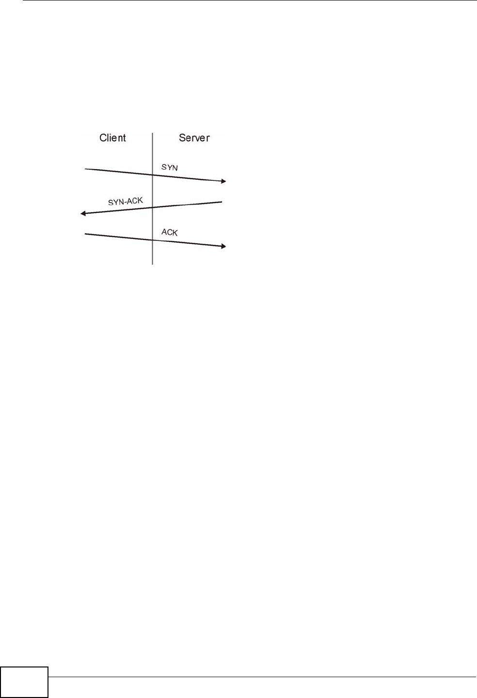
Chapter 12 Firewall
P-2612HWU-F1 User’s Guide
238
For TCP, half-open means that the session has not reached the established state-
the TCP three-way handshake has not yet been completed. Under normal
circumstances, the application that initiates a session sends a SYN (synchronize)
packet to the receiving server. The receiver sends back an ACK (acknowledgment)
packet and its own SYN, and then the initiator responds with an ACK
(acknowledgment). After this handshake, a connection is established.
Figure 145 Three-Way Handshake
For UDP, half-open means that the firewall has detected no return traffic. An
unusually high number (or arrival rate) of half-open sessions could indicate a DOS
attack.
12.4.1 Threshold Values
If everything is working properly, you probably do not need to change the
threshold settings as the default threshold values should work for most small
offices. Tune these parameters when you believe the ZyXEL Device has been
receiving DoS attacks that are not recorded in the logs or the logs show that the
ZyXEL Device is classifying normal traffic as DoS attacks. Factors influencing
choices for threshold values are:
1The maximum number of opened sessions.
2The minimum capacity of server backlog in your LAN network.
3The CPU power of servers in your LAN network.
4Network bandwidth.
5Type of traffic for certain servers.
Reduce the threshold values if your network is slower than average for any of
these factors (especially if you have servers that are slow or handle many tasks
and are often busy).
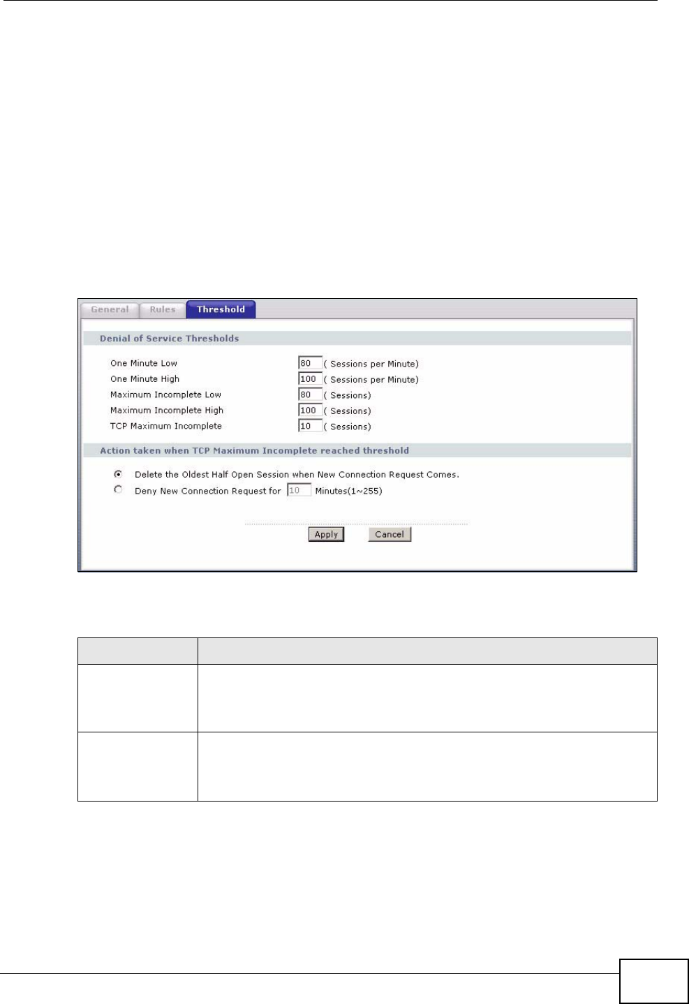
Chapter 12 Firewall
P-2612HWU-F1 User’s Guide 239
• If you often use P2P applications such as file sharing with eMule or eDonkey, it’s
recommended that you increase the threshold values since lots of sessions will
be established during a small period of time and the ZyXEL Device may classify
them as DoS attacks.
12.4.2 Configuring Firewall Thresholds
The ZyXEL Device also sends alerts whenever TCP Maximum Incomplete is
exceeded. The global values specified for the threshold and timeout apply to all
TCP connections.
Click Firewall > Threshold to bring up the next screen.
Figure 146 Security > Firewall > Threshold
The following table describes the labels in this screen.
Table 74 Security > Firewall > Threshold
LABEL DESCRIPTION
Denial of Service
Thresholds The ZyXEL Device measures both the total number of existing half-
open sessions and the rate of session establishment attempts. Both
TCP and UDP half-open sessions are counted in the total number and
rate measurements. Measurements are made once a minute.
One Minute Low This is the rate of new half-open sessions per minute that causes the
firewall to stop deleting half-open sessions. The ZyXEL Device
continues to delete half-open sessions as necessary, until the rate of
new connection attempts drops below this number.
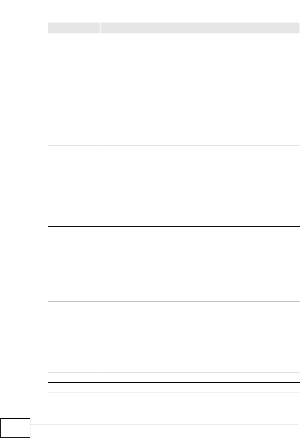
Chapter 12 Firewall
P-2612HWU-F1 User’s Guide
240
One Minute High This is the rate of new half-open sessions per minute that causes the
firewall to start deleting half-open sessions. When the rate of new
connection attempts rises above this number, the ZyXEL Device deletes
half-open sessions as required to accommodate new connection
attempts.
For example, if you set the one minute high to 100, the ZyXEL Device
starts deleting half-open sessions when more than 100 session
establishment attempts have been detected in the last minute. It stops
deleting half-open sessions when the number of session establishment
attempts detected in a minute goes below the number set as the one
minute low.
Maximum
Incomplete Low This is the number of existing half-open sessions that causes the
firewall to stop deleting half-open sessions. The ZyXEL Device
continues to delete half-open requests as necessary, until the number
of existing half-open sessions drops below this number.
Maximum
Incomplete High This is the number of existing half-open sessions that causes the
firewall to start deleting half-open sessions. When the number of
existing half-open sessions rises above this number, the ZyXEL Device
deletes half-open sessions as required to accommodate new
connection requests. Do not set Maximum Incomplete High to lower
than the current Maximum Incomplete Low number.
For example, if you set the maximum incomplete high to 100, the
ZyXEL Device starts deleting half-open sessions when the number of
existing half-open sessions rises above 100. It stops deleting half-open
sessions when the number of existing half-open sessions drops below
the number set as the maximum incomplete low.
TCP Maximum
Incomplete An unusually high number of half-open sessions with the same
destination host address could indicate that a DoS attack is being
launched against the host.
Specify the number of existing half-open TCP sessions with the same
destination host IP address that causes the firewall to start dropping
half-open sessions to that same destination host IP address. Enter a
number between 1 and 256. As a general rule, you should choose a
smaller number for a smaller network, a slower system or limited
bandwidth. The ZyXEL Device sends alerts whenever the TCP
Maximum Incomplete is exceeded.
Action taken
when TCP
Maximum
Incomplete
reached
threshold
Select the action that ZyXEL Device should take when the TCP
maximum incomplete threshold is reached. You can have the ZyXEL
Device either:
Delete the oldest half open session when a new connection request
comes.
or
Deny new connection requests for the number of minutes that you
specify (between 1 and 255).
Apply Click this to save your changes.
Cancel Click this to restore your previously saved settings.
Table 74 Security > Firewall > Threshold (continued)
LABEL DESCRIPTION

Chapter 12 Firewall
P-2612HWU-F1 User’s Guide 241
12.5 Firewall Technical Reference
This section provides some technical background information about the topics
covered in this chapter.
12.5.1 Firewall Rules Overview
Your customized rules take precedence and override the ZyXEL Device’s default
settings. The ZyXEL Device checks the source IP address, destination IP address
and IP protocol type of network traffic against the firewall rules (in the order you
list them). When the traffic matches a rule, the ZyXEL Device takes the action
specified in the rule.
Firewall rules are grouped based on the direction of travel of packets to which they
apply:
Note: The LAN includes both the LAN port and the WLAN.
By default, the ZyXEL Device’s stateful packet inspection allows packets traveling
in the following directions:
•LAN to LAN/ Router
These rules specify which computers on the LAN can manage the ZyXEL Device
(remote management) and communicate between networks or subnets
connected to the LAN interface (IP alias).
Note: You can also configure the remote management settings to allow only a specific
computer to manage the ZyXEL Device.
•LAN to WAN
These rules specify which computers on the LAN can access which computers or
services on the WAN.
By default, the ZyXEL Device’s stateful packet inspection drops packets traveling
in the following directions:
•WAN to LAN
These rules specify which computers on the WAN can access which computers
or services on the LAN.
Note: You also need to configure NAT port forwarding (or full featured NAT address
mapping rules) to allow computers on the WAN to access devices on the LAN.
•LAN to LAN/ Router •WAN to LAN
• LAN to WAN • WAN to WAN/ Router

Chapter 12 Firewall
P-2612HWU-F1 User’s Guide
242
•WAN to WAN/ Router
By default the ZyXEL Device stops computers on the WAN from managing the
ZyXEL Device or using the ZyXEL Device as a gateway to communicate with
other computers on the WAN. You could configure one of these rules to allow a
WAN computer to manage the ZyXEL Device.
Note: You also need to configure the remote management settings to allow a WAN
computer to manage the ZyXEL Device.
You may define additional rules and sets or modify existing ones but please
exercise extreme caution in doing so.
For example, you may create rules to:
• Block certain types of traffic, such as IRC (Internet Relay Chat), from the LAN to
the Internet.
• Allow certain types of traffic, such as Lotus Notes database synchronization,
from specific hosts on the Internet to specific hosts on the LAN.
• Allow everyone except your competitors to access a web server.
• Restrict use of certain protocols, such as Telnet, to authorized users on the LAN.
These custom rules work by comparing the source IP address, destination IP
address and IP protocol type of network traffic to rules set by the administrator.
Your customized rules take precedence and override the ZyXEL Device’s default
rules.
12.5.2 Guidelines For Enhancing Security With Your Firewall
1Change the default password via web configurator.
2Think about access control before you connect to the network in any way.
3Limit who can access your router.
4Don't enable any local service (such as telnet or FTP) that you don't use. Any
enabled service could present a potential security risk. A determined hacker might
be able to find creative ways to misuse the enabled services to access the firewall
or the network.
5For local services that are enabled, protect against misuse. Protect by configuring
the services to communicate only with specific peers, and protect by configuring
rules to block packets for the services at specific interfaces.
6Protect against IP spoofing by making sure the firewall is active.
7Keep the firewall in a secured (locked) room.
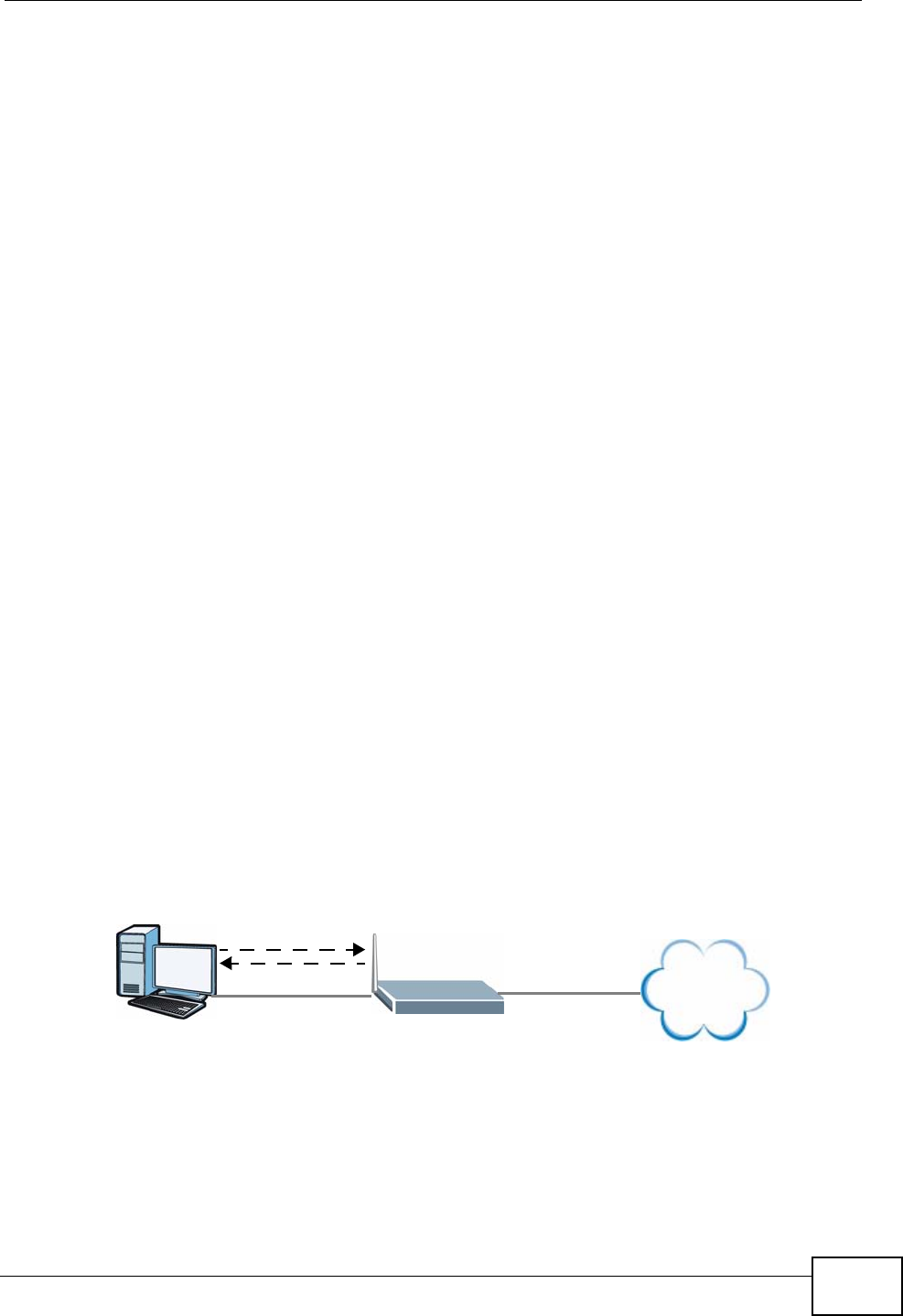
Chapter 12 Firewall
P-2612HWU-F1 User’s Guide 243
12.5.3 Security Considerations
Note: Incorrectly configuring the firewall may block valid access or introduce security
risks to the ZyXEL Device and your protected network. Use caution when
creating or deleting firewall rules and test your rules after you configure them.
Consider these security ramifications before creating a rule:
1Does this rule stop LAN users from accessing critical resources on the Internet?
For example, if IRC is blocked, are there users that require this service?
2Is it possible to modify the rule to be more specific? For example, if IRC is blocked
for all users, will a rule that blocks just certain users be more effective?
3Does a rule that allows Internet users access to resources on the LAN create a
security vulnerability? For example, if FTP ports (TCP 20, 21) are allowed from the
Internet to the LAN, Internet users may be able to connect to computers with
running FTP servers.
4Does this rule conflict with any existing rules?
Once these questions have been answered, adding rules is simply a matter of
entering the information into the correct fields in the web configurator screens.
12.5.4 Triangle Route
When the firewall is on, your ZyXEL Device acts as a secure gateway between your
LAN and the Internet. In an ideal network topology, all incoming and outgoing
network traffic passes through the ZyXEL Device to protect your LAN against
attacks.
Figure 147 Ideal Firewall Setup
12.5.4.1 The “Triangle Route” Problem
A traffic route is a path for sending or receiving data packets between two
Ethernet devices. You may have more than one connection to the Internet
(through one or more ISPs). If an alternate gateway is on the LAN (and its IP
address is in the same subnet as the ZyXEL Device’s LAN IP address), the “triangle
1
2
WAN
LAN
Internet
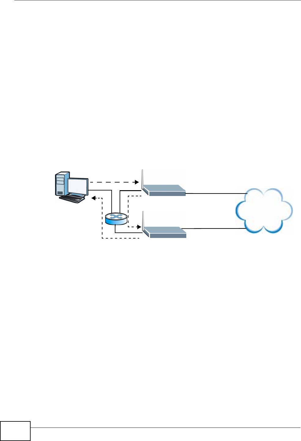
Chapter 12 Firewall
P-2612HWU-F1 User’s Guide
244
route” (also called asymmetrical route) problem may occur. The steps below
describe the “triangle route” problem.
1A computer on the LAN initiates a connection by sending out a SYN packet to a
receiving server on the WAN.
2The ZyXEL Device reroutes the SYN packet through Gateway A on the LAN to the
WAN.
3The reply from the WAN goes directly to the computer on the LAN without going
through the ZyXEL Device.
As a result, the ZyXEL Device resets the connection, as the connection has not
been acknowledged.
Figure 148 “Triangle Route” Problem
12.5.4.2 Solving the “Triangle Route” Problem
If you have the ZyXEL Device allow triangle route sessions, traffic from the WAN
can go directly to a LAN computer without passing through the ZyXEL Device and
its firewall protection.
Another solution is to use IP alias. IP alias allows you to partition your network
into logical sections over the same Ethernet interface. Your ZyXEL Device supports
up to three logical LAN interfaces with the ZyXEL Device being the gateway for
each logical network.
It’s like having multiple LAN networks that actually use the same physical cables
and ports. By putting your LAN and Gateway A in different subnets, all returning
network traffic must pass through the ZyXEL Device to your LAN. The following
steps describe such a scenario.
1A computer on the LAN initiates a connection by sending a SYN packet to a
receiving server on the WAN.
1
2
3
WAN
LAN
A
ISP 1
ISP 2
Internet
Chapter 12 Firewall
P-2612HWU-F1 User’s Guide 245
2The ZyXEL Device reroutes the packet to Gateway A, which is in Subnet 2.
3The reply from the WAN goes to the ZyXEL Device.
4The ZyXEL Device then sends it to the computer on the LAN in Subnet 1.
Figure 149 IP Alias
1
2
3
LAN
A
ISP 1
ISP 2
4
WAN
Subnet 1
Subnet 2
Internet

Chapter 12 Firewall
P-2612HWU-F1 User’s Guide
246

P-2612HWU-F1 User’s Guide 247
CHAPTER 13
Content Filtering
13.1 Overview
Internet content filtering allows you to block web sites based on keywords in the
URL.
13.1.1 What You Can Do in the Content Filter Screens
•Use the Keyword screen (Section 13.2 on page 250) to block web sites based
on a keyword in the URL.
•Use the Schedule screen (Section 13.3 on page 251) to specify the days and
times keyword blocking is active.
•Use the Trusted screen (Section 13.4 on page 252) to exclude computers and
other devices on your LAN from the keyword blocking filter.
13.1.2 What You Need to Know About Content Filtering
URL
The URL (Uniform Resource Locator) identifies and helps locates resources on a
network. On the Internet the URL is the web address that you type in the address
bar of your Internet browser, for example “http://www.zyxel.com”.
Finding Out More
See Section 13.1.4 on page 248 for an example of setting up content filtering.
13.1.3 Before You Begin
To use the Trusted screen, you need the IP addresses of devices on your
network. See the LAN section (Section 13.4 on page 252) for more information.
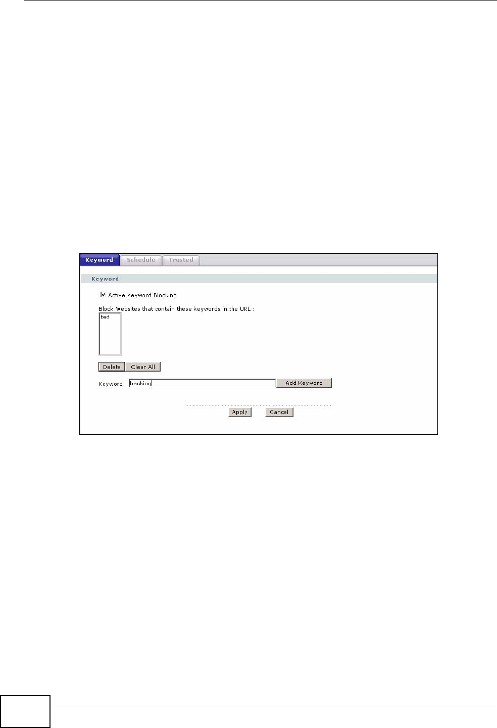
Chapter 13 Content Filtering
P-2612HWU-F1 User’s Guide
248
13.1.4 Content Filtering Example
The following shows the steps required for a parent (Bob) to set up content
filtering on a home network in order to limit his children’s access to certain web
sites. In the following example, all URLs containing the word ‘bad’ are blocked.
1Click Security > Content Filter to display the following screen.
2Select Active Keyword Blocking.
3In the Keyword field type keywords to identify websites to be blocked.
4Click Add Keyword for each keyword to be entered.
5Click Apply.
Figure 150 Security > Content Filter > Keyword: Example
Bob’s son arrives home from school at four, while his parents arrive later, at about
7pm. So keyword blocking is enabled for these times on weekdays and not on the
weekend when the parents are at home.
1Click Security > Content Filter > Schedule to display the following screen.
2Click Edit Daily to Block and select all weekdays.
3Under Start Time and End Time, type the times for blocking to begin and end
(4pm ~ 7pm in this example).
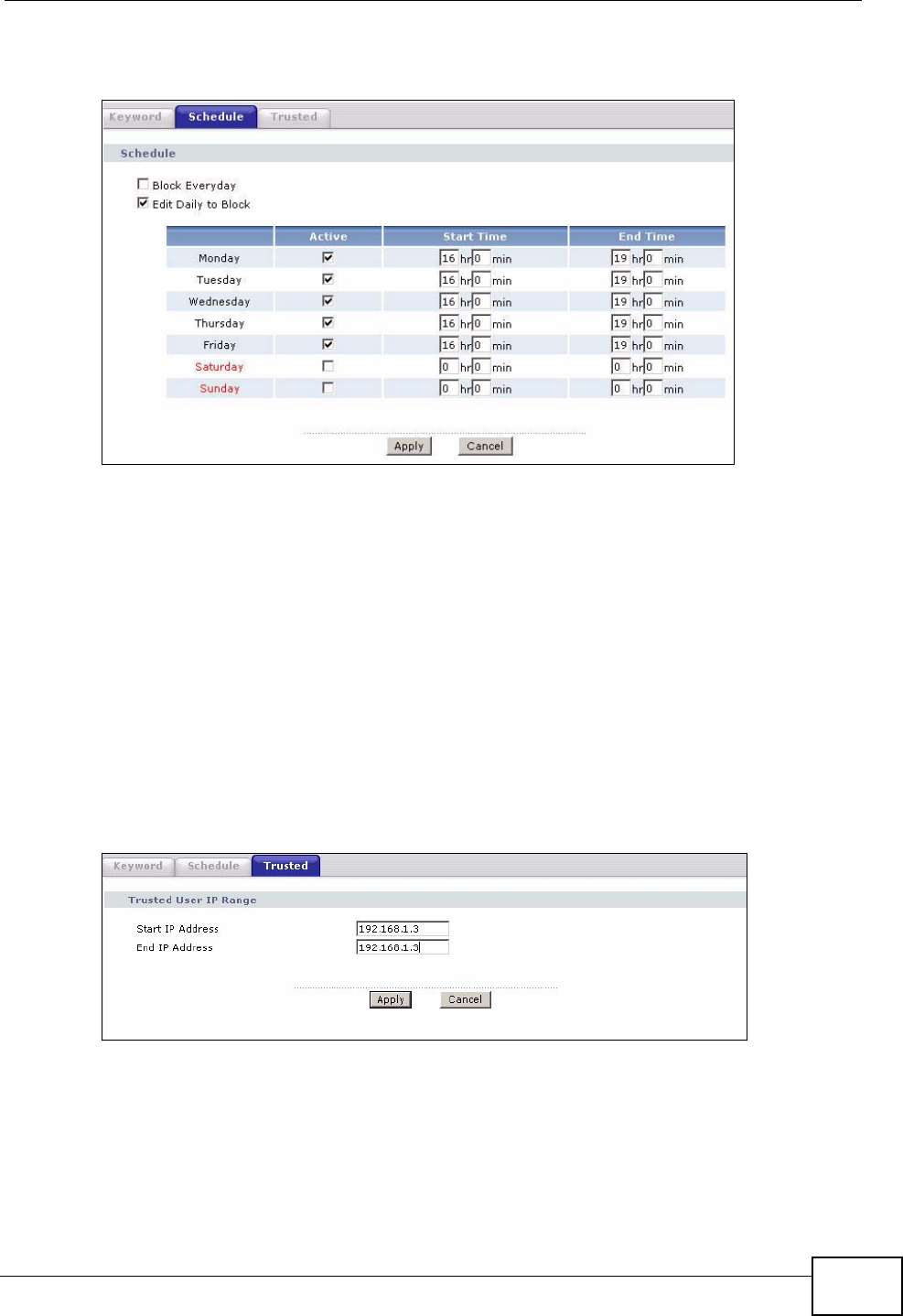
Chapter 13 Content Filtering
P-2612HWU-F1 User’s Guide 249
4Click Apply.
Figure 151 Security > Content Filter > Schedule: Example
The children can access the family computer in the living room, while only the
parents use another computer in the study room. So keyword blocking is only
needed on the family computer and the study computer can be excluded from
keyword blocking. Bob’s home network is on the domain “192.168.1.xxx”. Bob
gave his home computer a static IP address of 192.168.1.2 and the study
computer a static IP address of 192.168.1.3. To exclude the study computer from
keyword blocking he follows these steps.
1Click Security > Content Filter > Trusted to display the following screen.
2In the Start IP Address and End IP Address fields, type 192.168.1.3.
3Click Apply.
Figure 152 Security > Content Filter > Trusted: Example
That finishes setting up keyword blocking on the home computer.
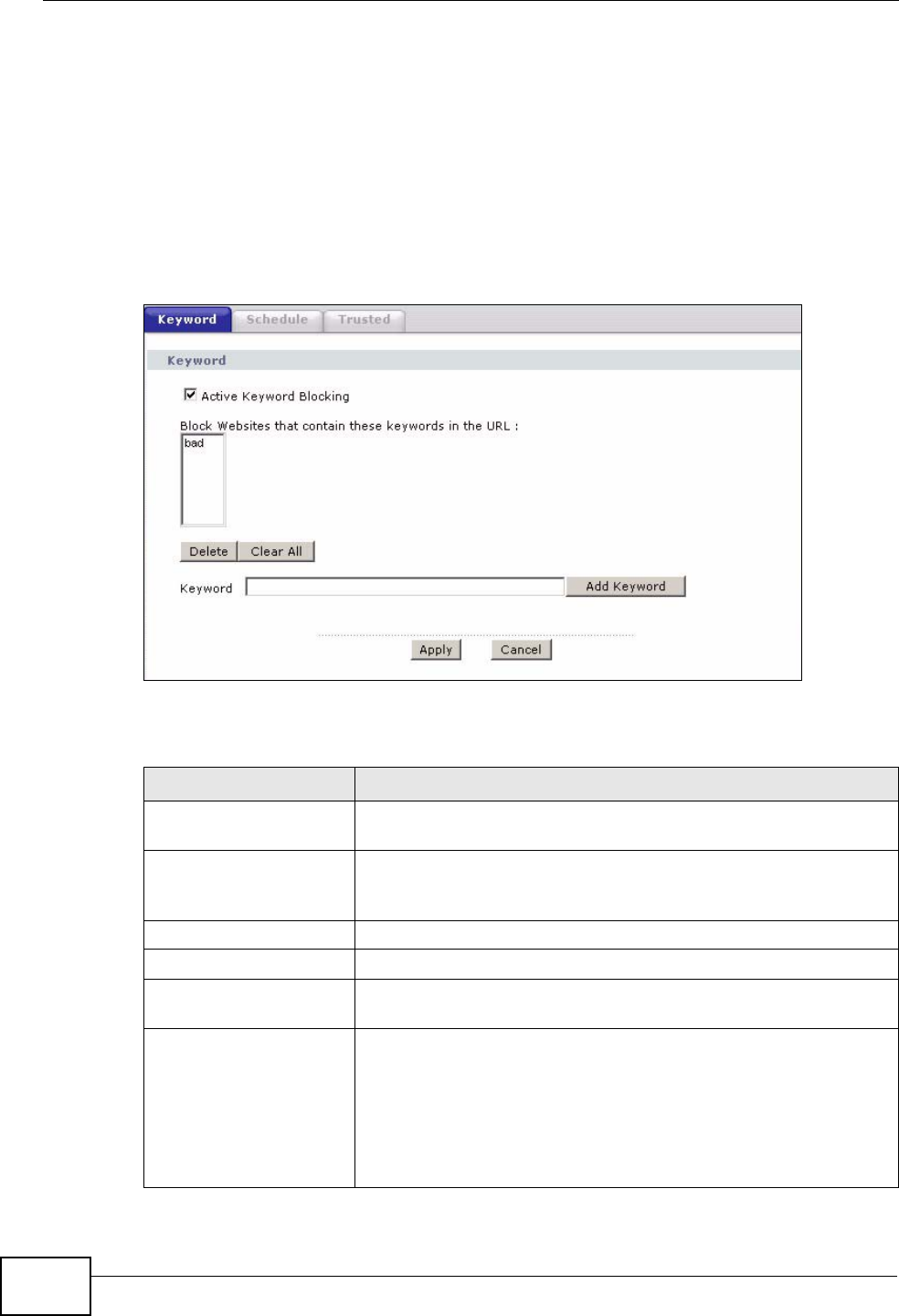
Chapter 13 Content Filtering
P-2612HWU-F1 User’s Guide
250
13.2 The Keyword Screen
Use this screen to block sites containing certain keywords in the URL. For
example, if you enable the keyword "bad", the ZyXEL Device blocks all sites
containing this keyword including the URL http://www.website.com/bad.html.
To have your ZyXEL Device block websites containing keywords in their URLs, click
Security > Content Filter. The screen appears as shown.
Figure 153 Security > Content Filtering > Keyword
The following table describes the labels in this screen.
Table 75 Security > Content Filtering > Keyword
LABEL DESCRIPTION
Active Keyword
Blocking Select this check box to enable this feature.
Block Websites that
contain these keywords
in the URL:
This box contains the list of all the keywords that you have
configured the ZyXEL Device to block.
Delete Highlight a keyword in the box and click this to remove it.
Clear All Click this to remove all of the keywords from the list.
Keyword Type a keyword in this field. You may use any character (up to
127 characters). Wildcards are not allowed.
Add Keyword Click this after you have typed a keyword.
Repeat this procedure to add other keywords. Up to 64
keywords are allowed.
When you try to access a web page containing a keyword, you
will get a message telling you that the content filter is blocking
this request.
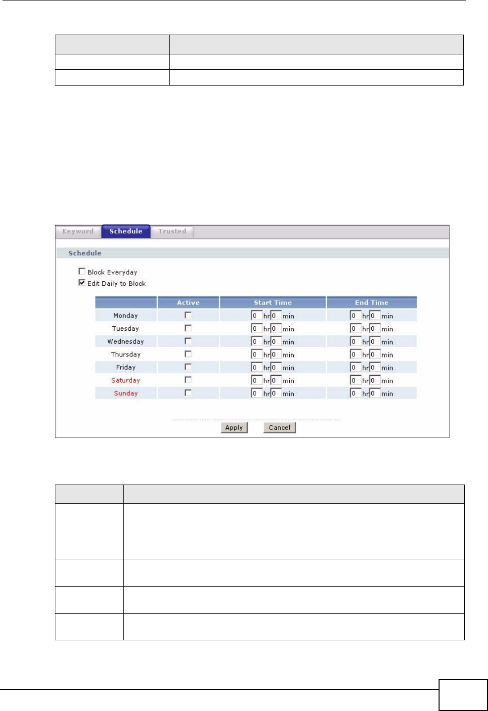
Chapter 13 Content Filtering
P-2612HWU-F1 User’s Guide 251
13.3 The Schedule Screen
Use this screen to set the days and times for the ZyXEL Device to perform content
filtering. Click Security > Content Filter > Schedule. The screen appears as
shown.
Figure 154 Security > Content Filter > Schedule
The following table describes the labels in this screen.
Apply Click this to save your changes.
Cancel Click this to restore your previously saved settings.
Table 75 Security > Content Filtering > Keyword (continued)
LABEL DESCRIPTION
Table 76 Security > Content Filter: Schedule
LABEL DESCRIPTION
Schedule Select Block Everyday to make the content filtering active everyday.
Otherwise, select Edit Daily to Block and configure which days of the
week (or everyday) and which time of the day you want the content
filtering to be active.
Active Select the check box to have the content filtering to be active on the
selected day.
Start TIme Enter the time when you want the content filtering to take effect in hour-
minute format.
End Time Enter the time when you want the content filtering to stop in hour-minute
format.
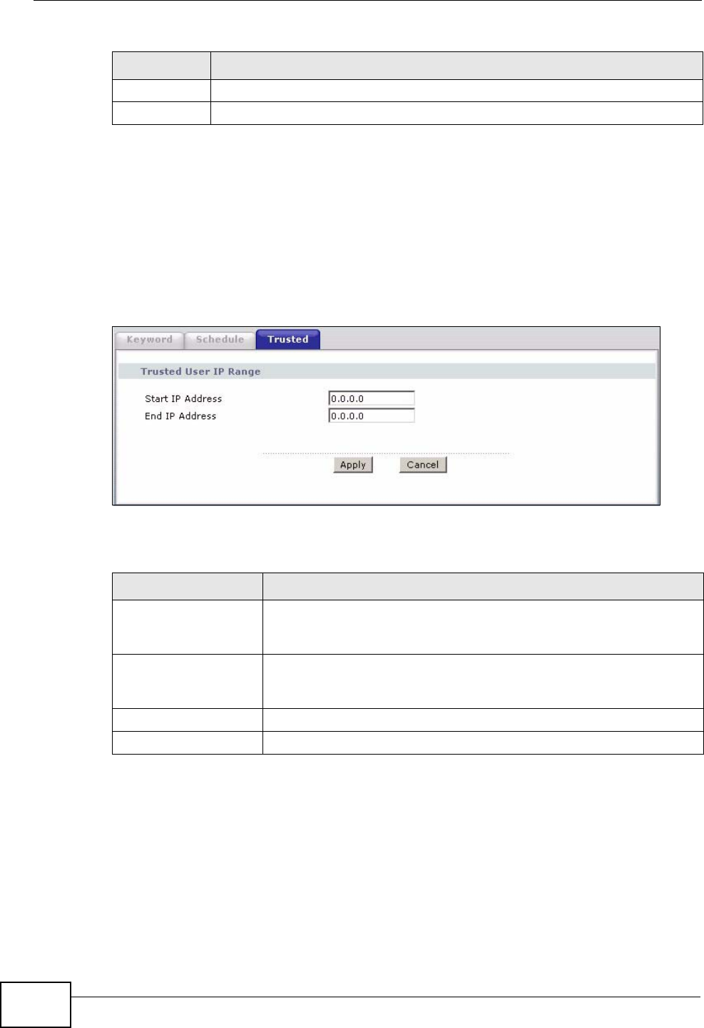
Chapter 13 Content Filtering
P-2612HWU-F1 User’s Guide
252
13.4 The Trusted Screen
Use this screen to exclude a range of users on the LAN from content filtering on
your ZyXEL Device. Click Security > Content Filter > Trusted. The screen
appears as shown.
Figure 155 Security > Content Filter: Trusted
The following table describes the labels in this screen.
Apply Click this to save your changes.
Cancel Click this to restore your previously saved settings.
Table 76 Security > Content Filter: Schedule (continued)
LABEL DESCRIPTION
Table 77 Security > Content Filter: Trusted
LABEL DESCRIPTION
Start IP Address Type the IP address of a computer (or the beginning IP address of
a specific range of computers) on the LAN that you want to
exclude from content filtering.
End IP Address Type the ending IP address of a specific range of users on your
LAN that you want to exclude from content filtering. Leave this
field blank if you want to exclude an individual computer.
Apply Click this to save your changes.
Cancel Click this to restore your previously saved settings.
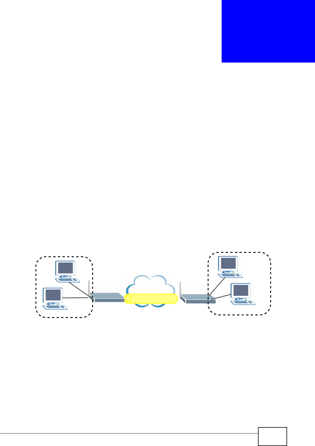
P-2612HWU-F1 User’s Guide 253
CHAPTER 14
VPN
14.1 Overview
A virtual private network (VPN) provides secure communications between sites
without the expense of leased site-to-site lines. A secure VPN is a combination of
tunneling, encryption, authentication, access control and auditing. It is used to
transport traffic over the Internet or any insecure network that uses TCP/IP for
communication.
Internet Protocol Security (IPSec) is a standards-based VPN that offers flexible
solutions for secure data communications across a public network like the
Internet. IPSec is built around a number of standardized cryptographic techniques
to provide confidentiality, data integrity and authentication at the IP layer. The
following figure is an example of an IPSec VPN tunnel.
Figure 156 VPN: Example
14.1.1 What You Can Do in the VPN Screens
•Use the Setup screen (Section 14.2 on page 256) to view the configured VPN
policies and add, edit or remove a VPN policy.
•Use the Monitor screen (Section 14.7 on page 271) to display and manage the
current active VPN connections.
•Use the VPN Global Setting screen (Section 14.8 on page 273) to allow
NetBIOS packets passing through the VPN connection.
VPN Tunnel
XY
Internet
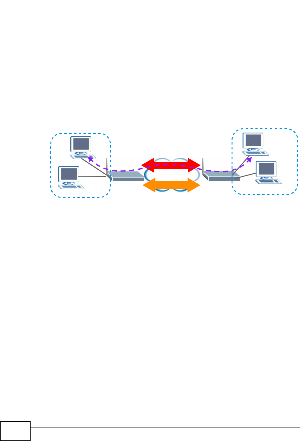
Chapter 14 VPN
P-2612HWU-F1 User’s Guide
254
14.1.2 What You Need to Know About IPSec VPN
A VPN tunnel is usually established in two phases. Each phase establishes a
security association (SA), a contract indicating what security parameters the
ZyXEL Device and the remote IPSec router will use. The first phase establishes an
Internet Key Exchange (IKE) SA between the ZyXEL Device and remote IPSec
router. The second phase uses the IKE SA to securely establish an IPSec SA
through which the ZyXEL Device and remote IPSec router can send data between
computers on the local network and remote network. The following figure
illustrates this.
Figure 157 VPN: IKE SA and IPSec SA
In this example, a computer in network A is exchanging data with a computer in
network B. Inside networks A and B, the data is transmitted the same way data is
normally transmitted in the networks. Between routers X and Y, the data is
protected by tunneling, encryption, authentication, and other security features of
the IPSec SA. The IPSec SA is established securely using the IKE SA that routers X
and Y established first.
My IP Address
My IP Address is the WAN IP address of the ZyXEL Device. The ZyXEL Device has
to rebuild the VPN tunnel if My IP Address changes after setup.
The following applies if this field is configured as 0.0.0.0:
• The ZyXEL Device uses the current ZyXEL Device WAN IP address (static or
dynamic) to set up the VPN tunnel.
Secure Gateway Address
Secure Gateway Address is the WAN IP address or domain name of the remote
IPSec router (secure gateway).
A
XY
Internet
B
IPSec SA
IKE SA

Chapter 14 VPN
P-2612HWU-F1 User’s Guide 255
If the remote secure gateway has a static WAN IP address, enter it in the Secure
Gateway Address field. You may alternatively enter the remote secure gateway’s
domain name (if it has one) in the Secure Gateway Address field.
You can also enter a remote secure gateway’s domain name in the Secure
Gateway Address field if the remote secure gateway has a dynamic WAN IP
address and is using DDNS. The ZyXEL Device has to rebuild the VPN tunnel each
time the remote secure gateway’s WAN IP address changes (there may be a delay
until the DDNS servers are updated with the remote gateway’s new WAN IP
address).
Dynamic Secure Gateway Address
If the remote secure gateway has a dynamic WAN IP address and does not use
DDNS, enter 0.0.0.0 as the secure gateway’s address. In this case only the
remote secure gateway can initiate SAs. This may be useful for telecommuters
initiating a VPN tunnel to the company network (see Section 14.9.12 on page 282
for configuration examples).
The Secure Gateway IP Address may be configured as 0.0.0.0 only when using
IKE key management and not Manual key management.
Finding Out More
See Section 14.9 on page 273 for advanced technical information on IPSec VPN.
14.1.3 Before You Begin
If a VPN tunnel uses Telnet, FTP, WWW, then you should configure remote
management (Remote MGMT) to allow access for that service.
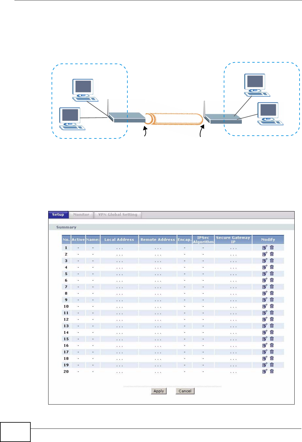
Chapter 14 VPN
P-2612HWU-F1 User’s Guide
256
14.2 VPN Setup Screen
The following figure helps explain the main fields in the web configurator.
Figure 158 IPSec Summary Fields
Local and remote IP addresses must be static.
Click Security > VPN to open the VPN Setup screen. This is a menu of your
IPSec rules (tunnels). The IPSec summary menu is read-only. Edit a VPN by
selecting an index number and then configuring its associated submenus.
Figure 159 Security > VPN > Setup
Local Network
Local IP Address My IP Address Secure Gateway IP Address
Remote Network
Remote IP Address
Remote
IPSec Router
VPN Tunnel
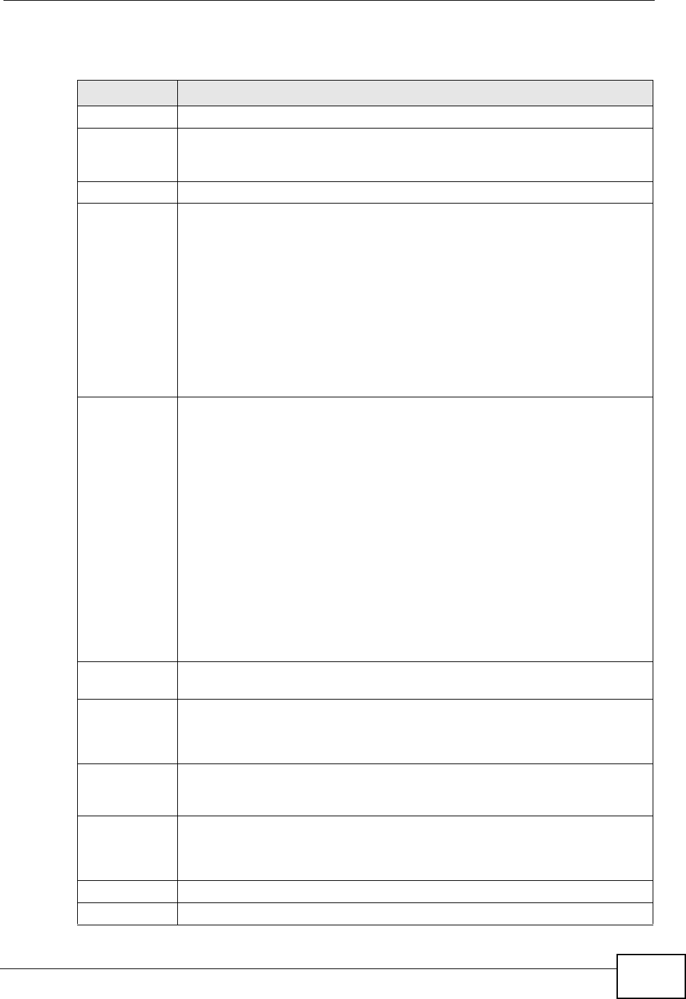
Chapter 14 VPN
P-2612HWU-F1 User’s Guide 257
The following table describes the fields in this screen.
Table 78 Security > VPN > Setup
LABEL DESCRIPTION
No. This is the VPN policy index number. Click a number to edit VPN policies.
Active This field displays whether the VPN policy is active or not. A Yes signifies
that this VPN policy is active. No signifies that this VPN policy is not
active.
Name This field displays the identification name for this VPN policy.
Local Address This is the IP address(es) of computer(s) on your local network behind
your ZyXEL Device.
The same (static) IP address is displayed twice when the Local Address
Type field in the VPN Setup - Edit screen is configured to Single.
The beginning and ending (static) IP addresses, in a range of computers
are displayed when the Local Address Type field in the VPN Setup -
Edit screen is configured to Range.
A (static) IP address and a subnet mask are displayed when the Local
Address Type field in the VPN Setup - Edit screen is configured to
Subnet.
Remote
Address This is the IP address(es) of computer(s) on the remote network behind
the remote IPSec router.
This field displays N/A when the Secure Gateway Address field
displays 0.0.0.0. In this case only the remote IPSec router can initiate
the VPN.
The same (static) IP address is displayed twice when the Remote
Address Type field in the VPN Setup - Edit screen is configured to
Single.
The beginning and ending (static) IP addresses, in a range of computers
are displayed when the Remote Address Type field in the VPN Setup -
Edit screen is configured to Range.
A (static) IP address and a subnet mask are displayed when the Remote
Address Type field in the VPN Setup - Edit screen is configured to
Subnet.
Encap. This field displays Tunnel or Transport mode (Tunnel is the default
selection).
IPSec
Algorithm This field displays the security protocols used for an SA.
Both AH and ESP increase ZyXEL Device processing requirements and
communications latency (delay).
Secure
Gateway IP This is the static WAN IP address or URL of the remote IPSec router. This
field displays 0.0.0.0 when you configure the Secure Gateway Address
field in the VPN-IKE screen to 0.0.0.0.
Modify Click the Edit icon to go to the screen where you can edit the VPN
configuration.
Click the Remove icon to remove an existing VPN configuration.
Apply Click this to save your changes and apply them to the ZyXEL Device.
Cancel Click this return your settings to their last saved values.
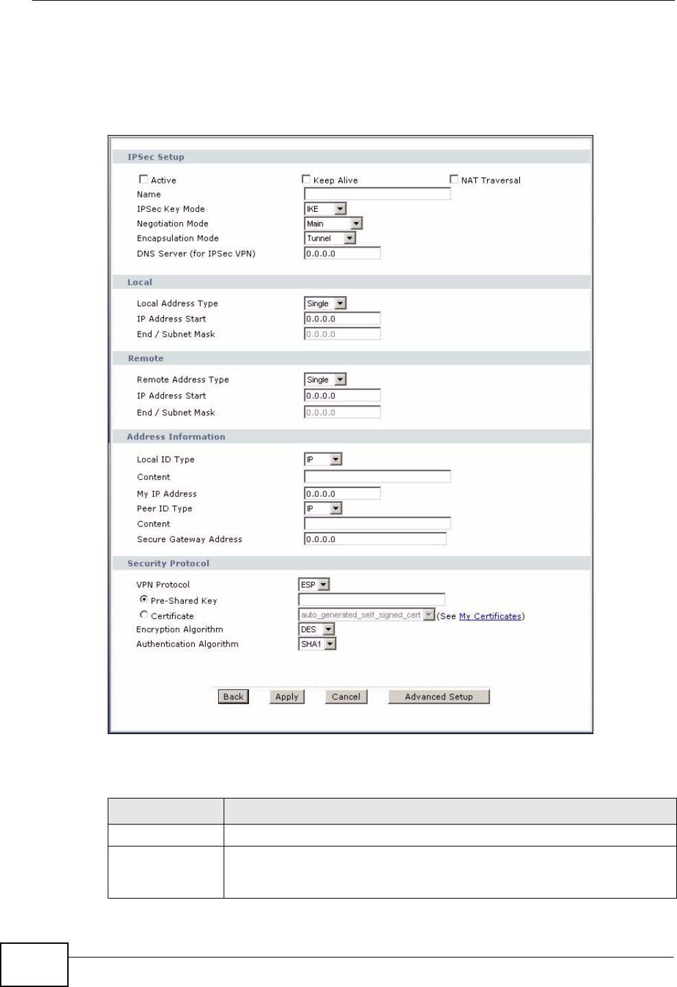
Chapter 14 VPN
P-2612HWU-F1 User’s Guide
258
14.3 The VPN Edit Screen
Click an Edit icon in the VPN Setup screen to edit VPN policies.
Figure 160 Security > VPN > Setup > Edit
The following table describes the fields in this screen.
Table 79 Security > VPN > Setup > Edit
LABEL DESCRIPTION
IPSec Setup
Active Select this check box to activate this VPN policy. This option
determines whether a VPN rule is applied before a packet leaves the
firewall.

Chapter 14 VPN
P-2612HWU-F1 User’s Guide 259
Keep Alive Select either Yes or No from the drop-down list box.
Select Yes to have the ZyXEL Device automatically reinitiate the SA
after the SA lifetime times out, even if there is no traffic. The remote
IPSec router must also have keep alive enabled in order for this feature
to work.
NAT Traversal This function is available if the VPN Protocol is ESP.
Select this check box if you want to set up a VPN tunnel when there are
NAT routers between the ZyXEL Device and remote IPSec router. The
remote IPSec router must also enable NAT traversal, and the NAT
routers have to forward UDP port 500 packets to the remote IPSec
router behind the NAT router.
Name Type up to 32 characters to identify this VPN policy. You may use any
character, including spaces, but the ZyXEL Device drops trailing spaces.
IPSec Key Mode Select IKE or Manual from the drop-down list box. IKE provides more
protection so it is generally recommended. Manual is a useful option
for troubleshooting if you have problems using IKE key management.
Negotiation
Mode Select Main or Aggressive from the drop-down list box. Multiple SAs
connecting through a secure gateway must have the same negotiation
mode.
Encapsulation
Mode Select Tunnel mode or Transport mode from the drop-down list box.
DNS Server (for
IPSec VPN) If there is a private DNS server that services the VPN, type its IP
address here. The ZyXEL Device assigns this additional DNS server to
the ZyXEL Device's DHCP clients that have IP addresses in this IPSec
rule's range of local addresses.
A DNS server allows clients on the VPN to find other computers and
servers on the VPN by their (private) domain names.
Local Specify the IP addresses of the devices behind the ZyXEL Device that
can use the VPN tunnel. The local IP addresses must correspond to the
remote IPSec router's configured remote IP addresses.
Two active SAs cannot have the local and remote IP address(es) both
the same. Two active SAs can have the same local or remote IP
address, but not both. You can configure multiple SAs between the
same local and remote IP addresses, as long as only one is active at
any time.
Local Address
Type Use the drop-down menu to choose Single, Range, or Subnet. Select
Single for a single IP address. Select Range for a specific range of IP
addresses. Select Subnet to specify IP addresses on a network by
their subnet mask.
IP Address Start When the Local Address Type field is configured to Single, enter a
(static) IP address on the LAN behind your ZyXEL Device. When the
Local Address Type field is configured to Range, enter the beginning
(static) IP address, in a range of computers on your LAN behind your
ZyXEL Device. When the Local Address Type field is configured to
Subnet, this is a (static) IP address on the LAN behind your ZyXEL
Device.
Table 79 Security > VPN > Setup > Edit
LABEL DESCRIPTION
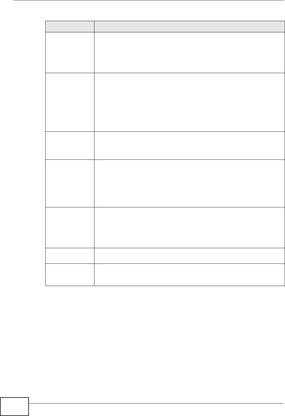
Chapter 14 VPN
P-2612HWU-F1 User’s Guide
260
End / Subnet
Mask When the Local Address Type field is configured to Single, this field
is N/A. When the Local Address Type field is configured to Range,
enter the end (static) IP address, in a range of computers on the LAN
behind your ZyXEL Device. When the Local Address Type field is
configured to Subnet, this is a subnet mask on the LAN behind your
ZyXEL Device.
Remote Specify the IP addresses of the devices behind the remote IPSec router
that can use the VPN tunnel. The remote IP addresses must correspond
to the remote IPSec router's configured local IP addresses.
Two active SAs cannot have the local and remote IP address(es) both
the same. Two active SAs can have the same local or remote IP
address, but not both. You can configure multiple SAs between the
same local and remote IP addresses, as long as only one is active at
any time.
Remote Address
Type Use the drop-down menu to choose Single, Range, or Subnet. Select
Single with a single IP address. Select Range for a specific range of IP
addresses. Select Subnet to specify IP addresses on a network by
their subnet mask.
IP Address Start When the Remote Address Type field is configured to Single, enter a
(static) IP address on the network behind the remote IPSec router.
When the Remote Address Type field is configured to Range, enter
the beginning (static) IP address, in a range of computers on the
network behind the remote IPSec router. When the Remote Address
Type field is configured to Subnet, enter a (static) IP address on the
network behind the remote IPSec router.
End / Subnet
Mask When the Remote Address Type field is configured to Single, this
field is N/A. When the Remote Address Type field is configured to
Range, enter the end (static) IP address, in a range of computers on
the network behind the remote IPSec router. When the Remote
Address Type field is configured to Subnet, enter a subnet mask on
the network behind the remote IPSec router.
Address
Information
Local ID Type Select IP to identify this ZyXEL Device by its IP address.
Select DNS to identify this ZyXEL Device by a domain name.
Select E-mail to identify this ZyXEL Device by an e-mail address.
Table 79 Security > VPN > Setup > Edit
LABEL DESCRIPTION
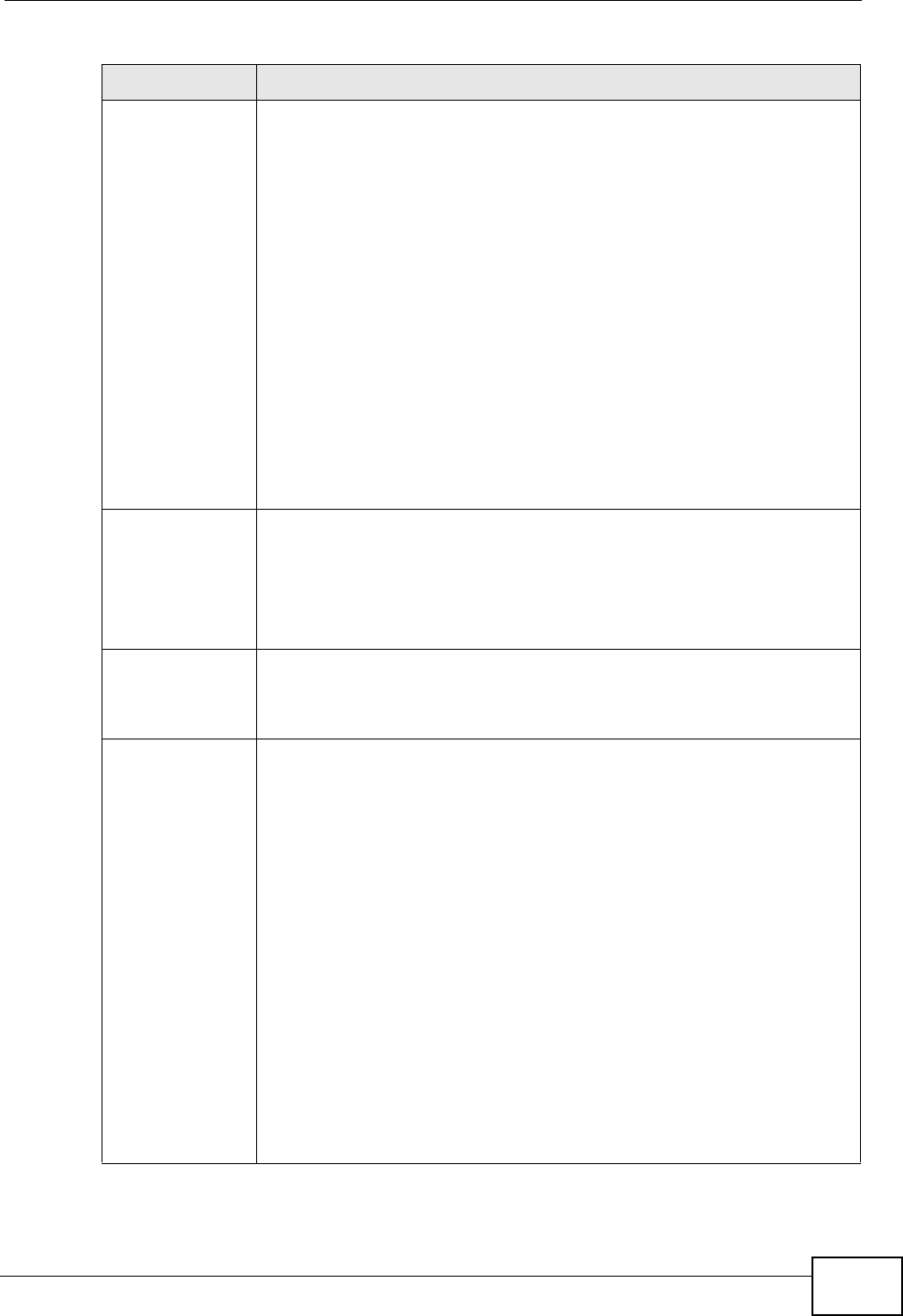
Chapter 14 VPN
P-2612HWU-F1 User’s Guide 261
Content When you select IP in the Local ID Type field, type the IP address of
your computer in the local Content field. The ZyXEL Device
automatically uses the IP address in the My IP Address field (refer to
the My IP Address field description) if you configure the local
Content field to 0.0.0.0 or leave it blank.
It is recommended that you type an IP address other than 0.0.0.0 in
the local Content field or use the DNS or E-mail ID type in the
following situations.
When there is a NAT router between the two IPSec routers.
When you want the remote IPSec router to be able to distinguish
between VPN connection requests that come in from IPSec routers with
dynamic WAN IP addresses.
When you select DNS or E-mail in the Local ID Type field, type a
domain name or e-mail address by which to identify this ZyXEL Device
in the local Content field. Use up to 31 ASCII characters including
spaces, although trailing spaces are truncated. The domain name or e-
mail address is for identification purposes only and can be any string.
My IP Address Enter the WAN IP address of your ZyXEL Device. The VPN tunnel has to
be rebuilt if this IP address changes.
The following applies if this field is configured as 0.0.0.0:
The ZyXEL Device uses the current ZyXEL Device WAN IP address
(static or dynamic) to set up the VPN tunnel.
Peer ID Type Select IP to identify the remote IPSec router by its IP address.
Select DNS to identify the remote IPSec router by a domain name.
Select E-mail to identify the remote IPSec router by an e-mail
address.
Content The configuration of the peer content depends on the peer ID type.
For IP, type the IP address of the computer with which you will make
the VPN connection. If you configure this field to 0.0.0.0 or leave it
blank, the ZyXEL Device will use the address in the Secure Gateway
Address field (refer to the Secure Gateway Address field
description).
For DNS or E-mail, type a domain name or e-mail address by which to
identify the remote IPSec router. Use up to 31 ASCII characters
including spaces, although trailing spaces are truncated. The domain
name or e-mail address is for identification purposes only and can be
any string.
It is recommended that you type an IP address other than 0.0.0.0 or
use the DNS or E-mail ID type in the following situations:
When there is a NAT router between the two IPSec routers.
When you want the ZyXEL Device to distinguish between VPN
connection requests that come in from remote IPSec routers with
dynamic WAN IP addresses.
Table 79 Security > VPN > Setup > Edit
LABEL DESCRIPTION
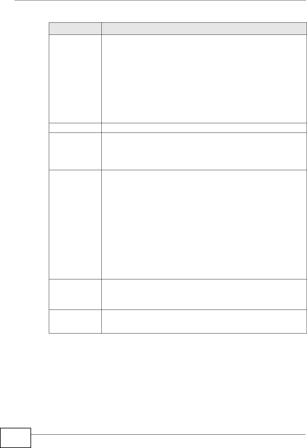
Chapter 14 VPN
P-2612HWU-F1 User’s Guide
262
Secure Gateway
Address Type the WAN IP address or the URL (up to 31 characters) of the IPSec
router with which you're making the VPN connection. Set this field to
0.0.0.0 if the remote IPSec router has a dynamic WAN IP address (the
IPSec Key Mode field must be set to IKE).
In order to have more than one active rule with the Secure Gateway
Address field set to 0.0.0.0, the ranges of the local IP addresses
cannot overlap between rules.
If you configure an active rule with 0.0.0.0 in the Secure Gateway
Address field and the LAN’s full IP address range as the local IP
address, then you cannot configure any other active rules with the
Secure Gateway Address field set to 0.0.0.0.
Security Protocol
VPN Protocol Select ESP if you want to use ESP (Encapsulation Security Payload).
The ESP protocol (RFC 2406) provides encryption as well as some of
the services offered by AH. If you select ESP here, you must select
options from the Encryption Algorithm and Authentication
Algorithm fields (described below).
Pre-Shared Key Click the button to use a pre-shared key for authentication, and type in
your pre-shared key. A pre-shared key identifies a communicating
party during a phase 1 IKE negotiation. It is called "pre-shared"
because you have to share it with another party before you can
communicate with them over a secure connection.
Type from 8 to 31 case-sensitive ASCII characters or from 16 to 62
hexadecimal ("0-9", "A-F") characters. You must precede a
hexadecimal key with a "0x” (zero x), which is not counted as part of
the 16 to 62 character range for the key. For example, in
"0x0123456789ABCDEF", “0x” denotes that the key is hexadecimal
and “0123456789ABCDEF” is the key itself.
Both ends of the VPN tunnel must use the same pre-shared key. You
will receive a “PYLD_MALFORMED” (payload malformed) packet if the
same pre-shared key is not used on both ends.
Certificate Click the button to use a certificate for authentication. Select the
certificate you want to use from the list. You can create, import and
configure certificates in the Security > Certificates screens, or click
the My Certificates link.
My Certificates Click this to go to the Security > Certificates > My Certificates
screen. If you do not click Apply first, your VPN settings will not be
saved.
Table 79 Security > VPN > Setup > Edit
LABEL DESCRIPTION
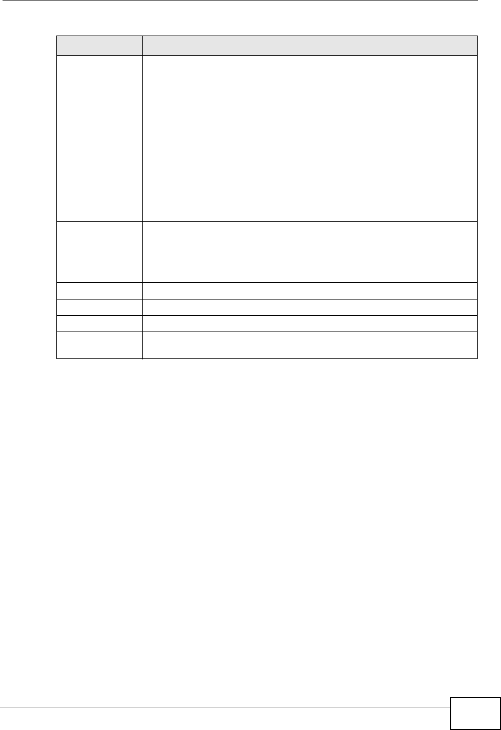
Chapter 14 VPN
P-2612HWU-F1 User’s Guide 263
Encryption
Algorithm Select DES, 3DES, AES or NULL from the drop-down list box.
When you use one of these encryption algorithms for data
communications, both the sending device and the receiving device
must use the same secret key, which can be used to encrypt and
decrypt the message or to generate and verify a message
authentication code. The DES encryption algorithm uses a 56-bit key.
Triple DES (3DES) is a variation on DES that uses a 168-bit key. As a
result, 3DES is more secure than DES. It also requires more
processing power, resulting in increased latency and decreased
throughput. This implementation of AES uses a 128-bit key. AES is
faster than 3DES.
Select NULL to set up a tunnel without encryption. When you select
NULL, you do not enter an encryption key.
Authentication
Algorithm Select SHA1 or MD5 from the drop-down list box. MD5 (Message
Digest 5) and SHA1 (Secure Hash Algorithm) are hash algorithms used
to authenticate packet data. The SHA1 algorithm is generally
considered stronger than MD5, but is slower. Select MD5 for minimal
security and SHA-1 for maximum security.
Back Click Back to return to the previous screen.
Apply Click Apply to save your changes back to the ZyXEL Device.
Cancel Click Cancel to begin configuring this screen afresh.
Advanced Setup Click Advanced Setup to configure more detailed settings of your IKE
key management.
Table 79 Security > VPN > Setup > Edit
LABEL DESCRIPTION
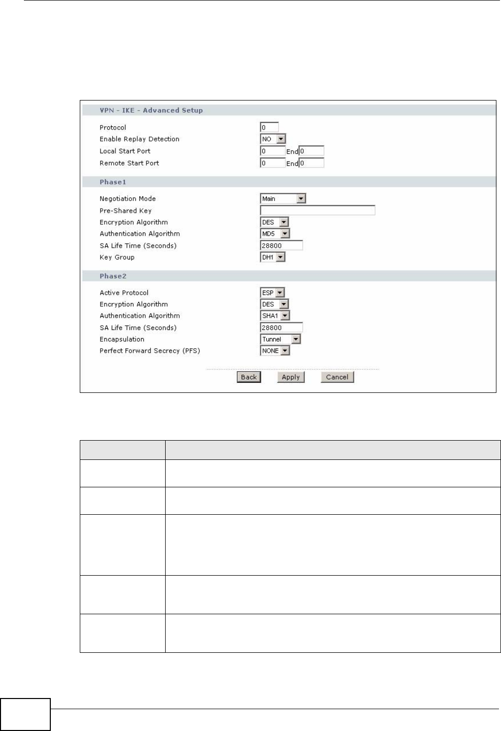
Chapter 14 VPN
P-2612HWU-F1 User’s Guide
264
14.4 Configuring Advanced IKE Settings
Click Advanced Setup in the VPN Setup-Edit screen to open this screen.
Figure 161 Security > VPN > Setup > Edit > Advanced Setup
The following table describes the fields in this screen.
Table 80 Security > VPN > Setup > Edit > Advanced Setup
LABEL DESCRIPTION
VPN - IKE -
Advanced Setup
Protocol Enter 1 for ICMP, 6 for TCP, 17 for UDP, and so on. 0 is the default and
signifies any protocol.
Enable Replay
Detection As a VPN setup is processing intensive, the system is vulnerable to
Denial of Service (DoS) attacks The IPSec receiver can detect and
reject old or duplicate packets to protect against replay attacks. Select
YES from the drop-down menu to enable replay detection, or select
NO to disable it.
Local Start Port 0 is the default and signifies any port. Type a port number from 0 to
65535. Some of the most common IP ports are: 21, FTP; 53, DNS; 23,
Telnet; 80, HTTP; 25, SMTP; 110, POP3.
End Enter a port number in this field to define a port range. This port
number must be greater than that specified in the previous field. If
Local Start Port is left at 0, End will also remain at 0.
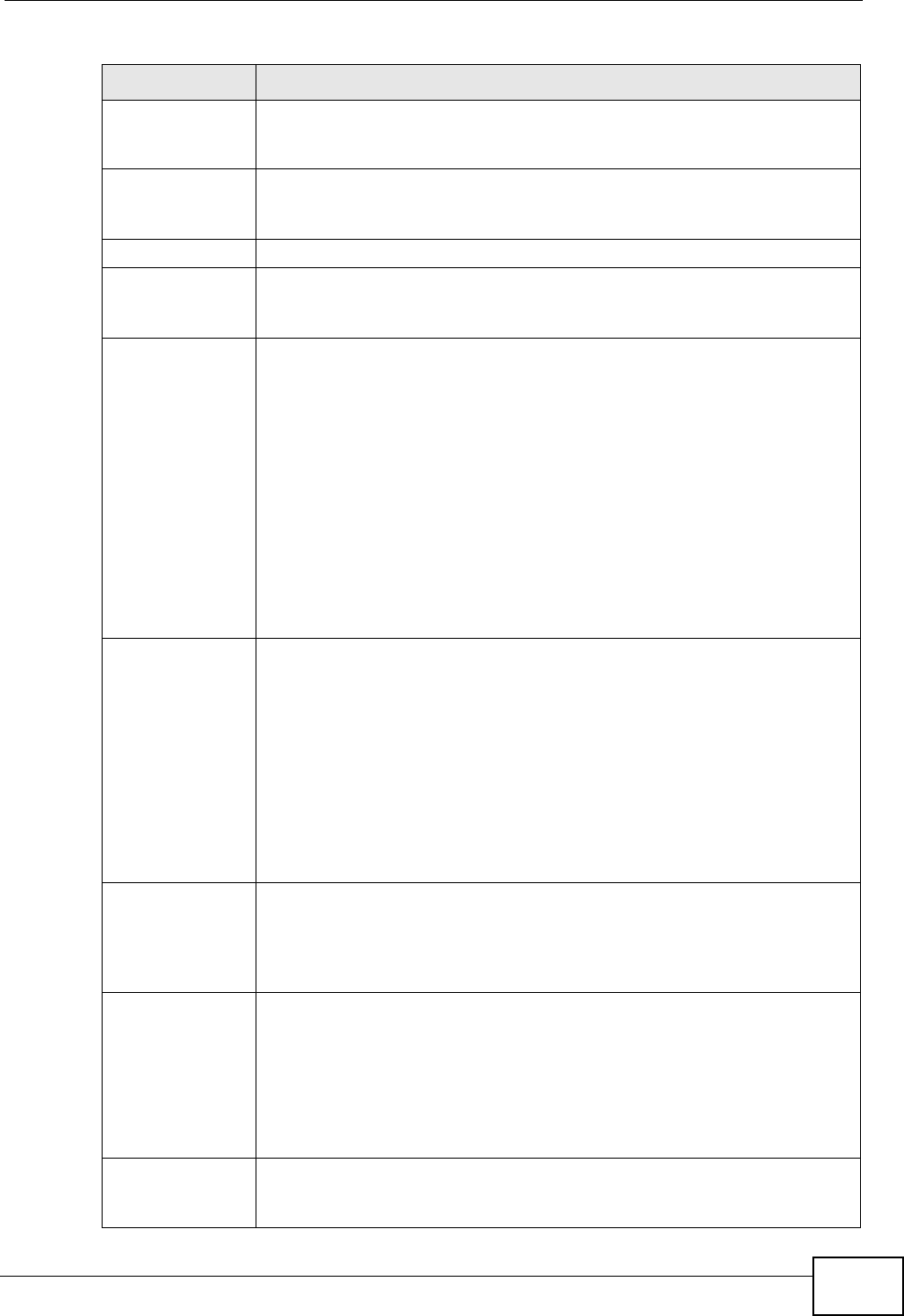
Chapter 14 VPN
P-2612HWU-F1 User’s Guide 265
Remote Start
Port 0 is the default and signifies any port. Type a port number from 0 to
65535. Some of the most common IP ports are: 21, FTP; 53, DNS; 23,
Telnet; 80, HTTP; 25, SMTP; 110, POP3.
End Enter a port number in this field to define a port range. This port
number must be greater than that specified in the previous field. If
Remote Start Port is left at 0, End will also remain at 0.
Phase 1
Negotiation
Mode Select Main or Aggressive from the drop-down list box. Multiple SAs
connecting through a secure gateway must have the same negotiation
mode.
Pre-Shared Key Type your pre-shared key in this field. A pre-shared key identifies a
communicating party during a phase 1 IKE negotiation. It is called
"pre-shared" because you have to share it with another party before
you can communicate with them over a secure connection.
Type from 8 to 31 case-sensitive ASCII characters or from 16 to 62
hexadecimal ("0-9", "A-F") characters. You must precede a
hexadecimal key with a "0x” (zero x), which is not counted as part of
the 16 to 62-character range for the key. For example, in
"0x0123456789ABCDEF", “0x” denotes that the key is hexadecimal
and “0123456789ABCDEF” is the key itself.
Both ends of the VPN tunnel must use the same pre-shared key. You
will receive a “PYLD_MALFORMED” (payload malformed) packet if the
same pre-shared key is not used on both ends.
Encryption
Algorithm Select DES, 3DES or AES from the drop-down list box.
When you use one of these encryption algorithms for data
communications, both the sending device and the receiving device
must use the same secret key, which can be used to encrypt and
decrypt the message or to generate and verify a message
authentication code. The DES encryption algorithm uses a 56-bit key.
Triple DES (3DES) is a variation on DES that uses a 168-bit key. As a
result, 3DES is more secure than DES. It also requires more
processing power, resulting in increased latency and decreased
throughput. This implementation of AES uses a 128-bit key. AES is
faster than 3DES.
Authentication
Algorithm Select SHA1 or MD5 from the drop-down list box. MD5 (Message
Digest 5) and SHA1 (Secure Hash Algorithm) are hash algorithms
used to authenticate packet data. The SHA1 algorithm is generally
considered stronger than MD5, but is slower. Select MD5 for minimal
security and SHA-1 for maximum security.
SA Life Time
(Seconds) Define the length of time before an IPSec SA automatically
renegotiates in this field. It may range from 60 to 3,000,000 seconds
(almost 35 days).
A short SA Life Time increases security by forcing the two VPN
gateways to update the encryption and authentication keys. However,
every time the VPN tunnel renegotiates, all users accessing remote
resources are temporarily disconnected.
Key Group You must choose a key group for phase 1 IKE setup. DH1 (default)
refers to Diffie-Hellman Group 1 a 768 bit random number. DH2 refers
to Diffie-Hellman Group 2 a 1024 bit (1Kb) random number.
Table 80 Security > VPN > Setup > Edit > Advanced Setup (continued)
LABEL DESCRIPTION
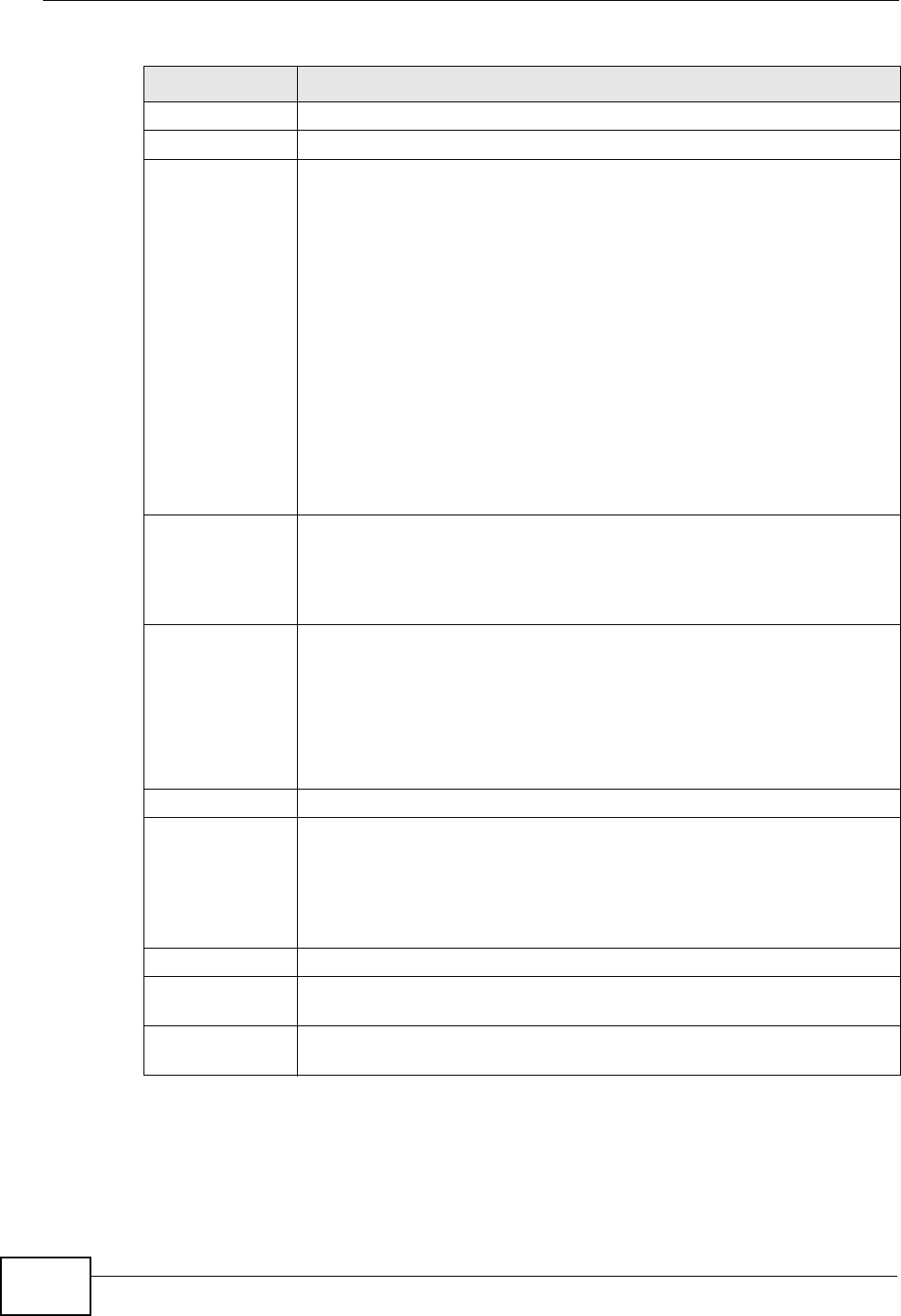
Chapter 14 VPN
P-2612HWU-F1 User’s Guide
266
Phase 2
Active Protocol Use the drop-down list box to choose from ESP or AH.
Encryption
Algorithm This field is available when you select ESP in the Active Protocol
field.
Select DES, 3DES, AES or NULL from the drop-down list box.
When you use one of these encryption algorithms for data
communications, both the sending device and the receiving device
must use the same secret key, which can be used to encrypt and
decrypt the message or to generate and verify a message
authentication code. The DES encryption algorithm uses a 56-bit key.
Triple DES (3DES) is a variation on DES that uses a 168-bit key. As a
result, 3DES is more secure than DES. It also requires more
processing power, resulting in increased latency and decreased
throughput. This implementation of AES uses a 128-bit key. AES is
faster than 3DES.
Select NULL to set up a tunnel without encryption. When you select
NULL, you do not enter an encryption key.
Authentication
Algorithm Select SHA1 or MD5 from the drop-down list box. MD5 (Message
Digest 5) and SHA1 (Secure Hash Algorithm) are hash algorithms used
to authenticate packet data. The SHA1 algorithm is generally
considered stronger than MD5, but is slower. Select MD5 for minimal
security and SHA-1 for maximum security.
SA Life Time
(Seconds) Define the length of time before an IKE SA automatically renegotiates
in this field. It may range from 60 to 3,000,000 seconds (almost 35
days).
A short SA Life Time increases security by forcing the two VPN
gateways to update the encryption and authentication keys. However,
every time the VPN tunnel renegotiates, all users accessing remote
resources are temporarily disconnected.
Encapsulation Select Tunnel mode or Transport mode from the drop-down list box.
Perfect Forward
Secrecy (PFS) Perfect Forward Secrecy (PFS) is disabled (NONE) by default in phase
2 IPSec SA setup. This allows faster IPSec setup, but is not so secure.
Choose DH1 or DH2 from the drop-down list box to enable PFS. DH1
refers to Diffie-Hellman Group 1 a 768 bit random number. DH2 refers
to Diffie-Hellman Group 2 a 1024 bit (1Kb) random number (more
secure, yet slower).
Back Click Back to return to the previous screen.
Apply Click Apply to save your changes back to the ZyXEL Device and return
to the VPN-IKE screen.
Cancel Click Cancel to return to the VPN-IKE screen without saving your
changes.
Table 80 Security > VPN > Setup > Edit > Advanced Setup (continued)
LABEL DESCRIPTION

Chapter 14 VPN
P-2612HWU-F1 User’s Guide 267
14.5 Manual Key Setup
Manual key management is useful if you have problems with IKE key
management.
14.5.1 Security Parameter Index (SPI)
An SPI is used to distinguish different SAs terminating at the same destination and
using the same IPSec protocol. This data allows for the multiplexing of SAs to a
single gateway. The SPI (Security Parameter Index) along with a destination IP
address uniquely identify a particular Security Association (SA). The SPI is
transmitted from the remote VPN gateway to the local VPN gateway. The local VPN
gateway then uses the network, encryption and key values that the administrator
associated with the SPI to establish the tunnel.
Current ZyXEL implementation assumes identical outgoing and incoming SPIs.
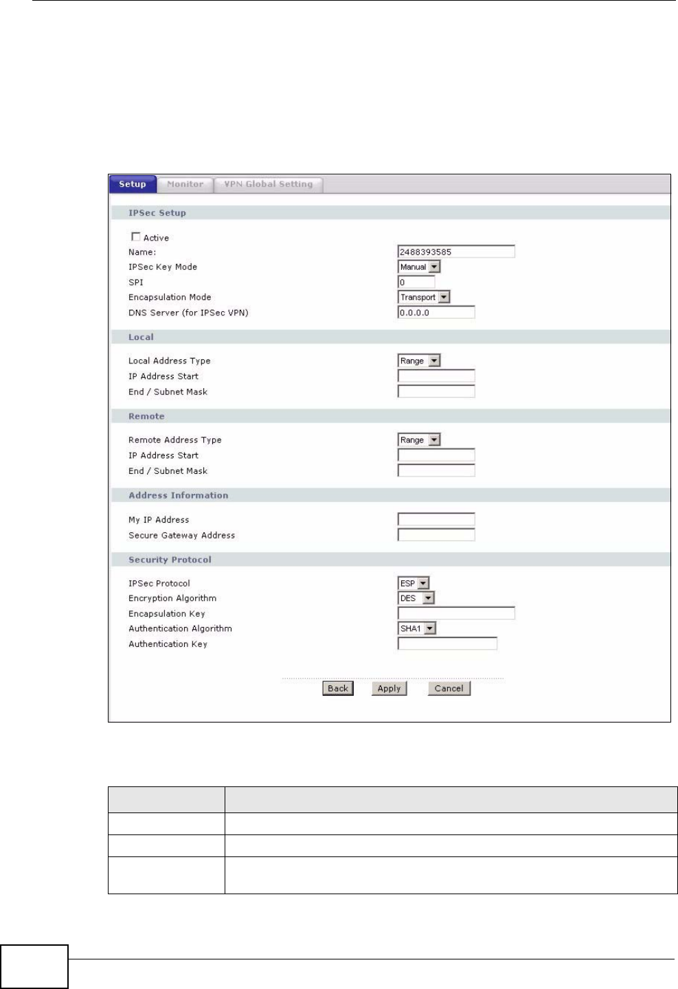
Chapter 14 VPN
P-2612HWU-F1 User’s Guide
268
14.6 Configuring Manual Key
You only configure VPN manual key when you select Manual in the IPSec Key
Mode field on the VPN Setup-Edit screen. This is the VPN Setup - Manual Key
screen as shown next.
Figure 162 Security > VPN > Setup > Manual Key
The following table describes the fields in this screen.
Table 81 Security > VPN > Setup > Manual Key
LABEL DESCRIPTION
IPSec Setup
Active Select this check box to activate this VPN policy.
Name Type up to 32 characters to identify this VPN policy. You may use any
character, including spaces, but the ZyXEL Device drops trailing spaces.
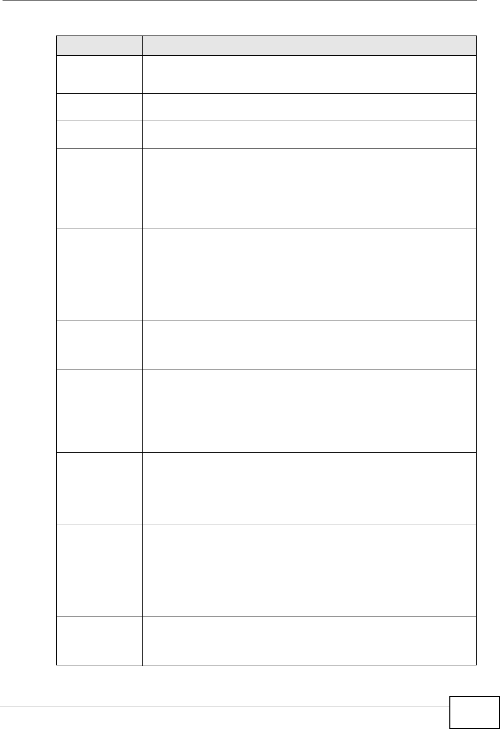
Chapter 14 VPN
P-2612HWU-F1 User’s Guide 269
IPSec Key Mode Select IKE or Manual from the drop-down list box. Manual is a useful
option for troubleshooting if you have problems using IKE key
management.
SPI Type a number (base 10) from 1 to 999999 for the Security Parameter
Index.
Encapsulation
Mode Select Tunnel mode or Transport mode from the drop-down list box.
DNS Server (for
IPSec VPN) If there is a private DNS server that services the VPN, type its IP
address here. The ZyXEL Device assigns this additional DNS server to
the ZyXEL Device 's DHCP clients that have IP addresses in this IPSec
rule's range of local addresses.
A DNS server allows clients on the VPN to find other computers and
servers on the VPN by their (private) domain names.
Local Local IP addresses must be static and correspond to the remote IPSec
router's configured remote IP addresses.
Two active SAs cannot have the local and remote IP address(es) both
the same. Two active SAs can have the same local or remote IP
address, but not both. You can configure multiple SAs between the
same local and remote IP addresses, as long as only one is active at
any time.
Local Address
Type Use the drop-down menu to choose Single, Range, or Subnet. Select
Single for a single IP address. Select Range for a specific range of IP
addresses. Select Subnet to specify IP addresses on a network by
their subnet mask.
IP Address Start When the Local Address Type field is configured to Single, enter a
(static) IP address on the LAN behind your ZyXEL Device. When the
Local Address Type field is configured to Range, enter the beginning
(static) IP address, in a range of computers on your LAN behind your
ZyXEL Device. When the Local Address Type field is configured to
Subnet, this is a (static) IP address on the LAN behind your ZyXEL
Device.
End / Subnet
Mask When the Local Address Type field is configured to Single, this field
is N/A. When the Local Address Type field is configured to Range,
enter the end (static) IP address, in a range of computers on the LAN
behind your ZyXEL Device. When the Local Address Type field is
configured to Subnet, this is a subnet mask on the LAN behind your
ZyXEL Device.
Remote Remote IP addresses must be static and correspond to the remote
IPSec router's configured local IP addresses.
Two active SAs cannot have the local and remote IP address(es) both
the same. Two active SAs can have the same local or remote IP
address, but not both. You can configure multiple SAs between the
same local and remote IP addresses, as long as only one is active at
any time.
Remote Address
Type Use the drop-down menu to choose Single, Range, or Subnet. Select
Single with a single IP address. Select Range for a specific range of IP
addresses. Select Subnet to specify IP addresses on a network by
their subnet mask.
Table 81 Security > VPN > Setup > Manual Key (continued)
LABEL DESCRIPTION
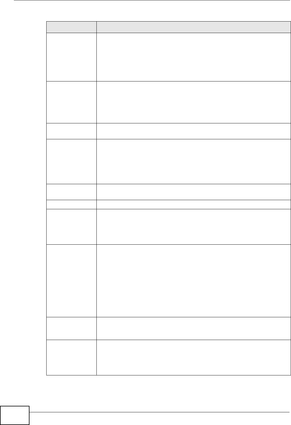
Chapter 14 VPN
P-2612HWU-F1 User’s Guide
270
IP Address Start When the Remote Address Type field is configured to Single, enter a
(static) IP address on the network behind the remote IPSec router.
When the Remote Address Type field is configured to Range, enter
the beginning (static) IP address, in a range of computers on the
network behind the remote IPSec router. When the Remote Address
Type field is configured to Subnet, enter a (static) IP address on the
network behind the remote IPSec router.
End / Subnet
Mask When the Remote Address Type field is configured to Single, this
field is N/A. When the Remote Address Type field is configured to
Range, enter the end (static) IP address, in a range of computers on
the network behind the remote IPSec router. When the Remote
Address Type field is configured to Subnet, enter a subnet mask on
the network behind the remote IPSec router.
Address
Information
My IP Address Enter the WAN IP address of your ZyXEL Device. The VPN tunnel has to
be rebuilt if this IP address changes.
The following applies if this field is configured as 0.0.0.0:
The ZyXEL Device uses the current ZyXEL Device WAN IP address
(static or dynamic) to set up the VPN tunnel.
Secure Gateway
Address Type the WAN IP address or the URL (up to 31 characters) of the IPSec
router with which you're making the VPN connection.
Security Protocol
IPSec Protocol Select ESP if you want to use ESP (Encapsulation Security Payload).
The ESP protocol (RFC 2406) provides encryption as well as some of
the services offered by AH. If you select ESP here, you must select
options from the Encryption Algorithm and Authentication
Algorithm fields (described next).
Encryption
Algorithm Select DES, 3DES or NULL from the drop-down list box.
When DES is used for data communications, both sender and receiver
must know the same secret key, which can be used to encrypt and
decrypt the message or to generate and verify a message
authentication code. The DES encryption algorithm uses a 56-bit key.
Triple DES (3DES) is a variation on DES that uses a 168-bit key. As a
result, 3DES is more secure than DES. It also requires more
processing power, resulting in increased latency and decreased
throughput. Select NULL to set up a tunnel without encryption. When
you select NULL, you do not enter an encryption key.
Encapsulation
Key (only with
ESP)
With DES, type a unique key 8 characters long. With 3DES, type a
unique key 24 characters long. Any characters may be used, including
spaces, but trailing spaces are truncated.
Authentication
Algorithm Select SHA1 or MD5 from the drop-down list box. MD5 (Message
Digest 5) and SHA1 (Secure Hash Algorithm) are hash algorithms used
to authenticate packet data. The SHA1 algorithm is generally
considered stronger than MD5, but is slower. Select MD5 for minimal
security and SHA-1 for maximum security.
Table 81 Security > VPN > Setup > Manual Key (continued)
LABEL DESCRIPTION
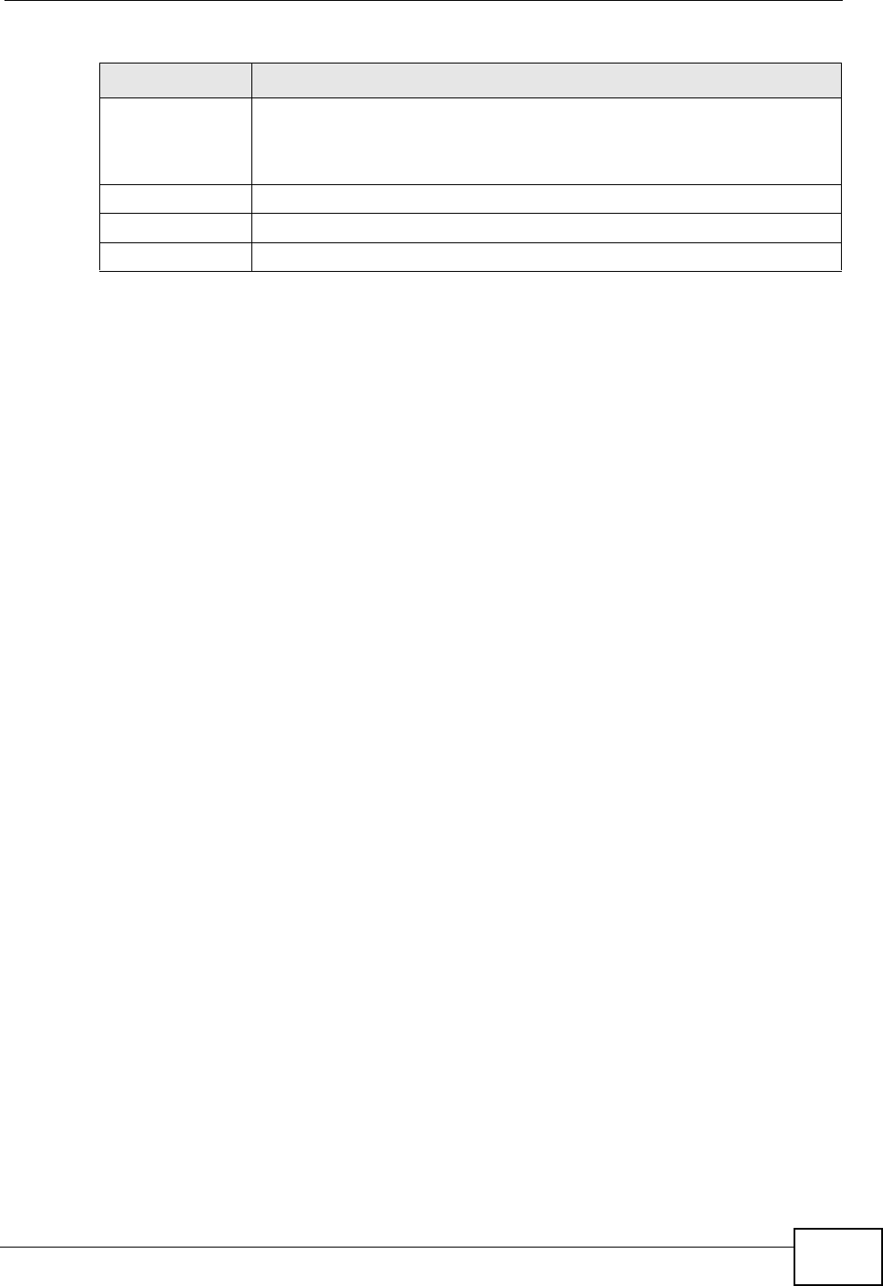
Chapter 14 VPN
P-2612HWU-F1 User’s Guide 271
14.7 Viewing SA Monitor
Click Security > VPN > Monitor to open the screen as shown. Use this screen to
display and manage active VPN connections.
A Security Association (SA) is the group of security settings related to a specific
VPN tunnel. This screen displays active VPN connections. Use Refresh to display
active VPN connections. This screen is read-only. The following table describes the
fields in this tab.
When there is outbound traffic but no inbound traffic, the SA times out
automatically after two minutes. A tunnel with no outbound or inbound traffic is
"idle" and does not timeout until the SA lifetime period expires. See Section
Authentication
Key Type a unique authentication key to be used by IPSec if applicable.
Enter 16 characters for MD5 authentication or 20 characters for SHA-
1 authentication. Any characters may be used, including spaces, but
trailing spaces are truncated.
Back Click Back to return to the previous screen.
Apply Click Apply to save your changes back to the ZyXEL Device.
Cancel Click Cancel to begin configuring this screen afresh.
Table 81 Security > VPN > Setup > Manual Key (continued)
LABEL DESCRIPTION
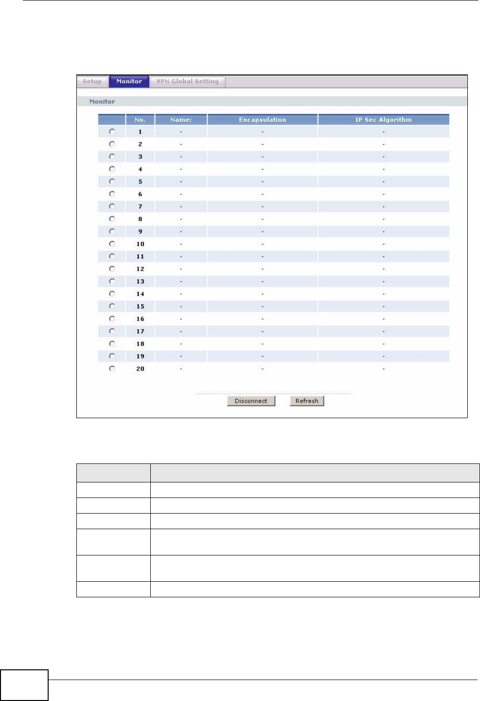
Chapter 14 VPN
P-2612HWU-F1 User’s Guide
272
14.9.7 on page 279on keep alive to have the ZyXEL Device renegotiate an IPSec
SA when the SA lifetime expires, even if there is no traffic.
Figure 163 Security > VPN > Monitor
The following table describes the fields in this screen.
Table 82 Security > VPN > Monitor
LABEL DESCRIPTION
No This is the security association index number.
Name This field displays the identification name for this VPN policy.
Encapsulation This field displays Tunnel or Transport mode.
IPSec
Algorithm This field displays the security protocol, encryption algorithm, and
authentication algorithm used in each VPN tunnel.
Disconnect Select one of the security associations, and then click Disconnect to
stop that security association.
Refresh Click Refresh to display the current active VPN connection(s).
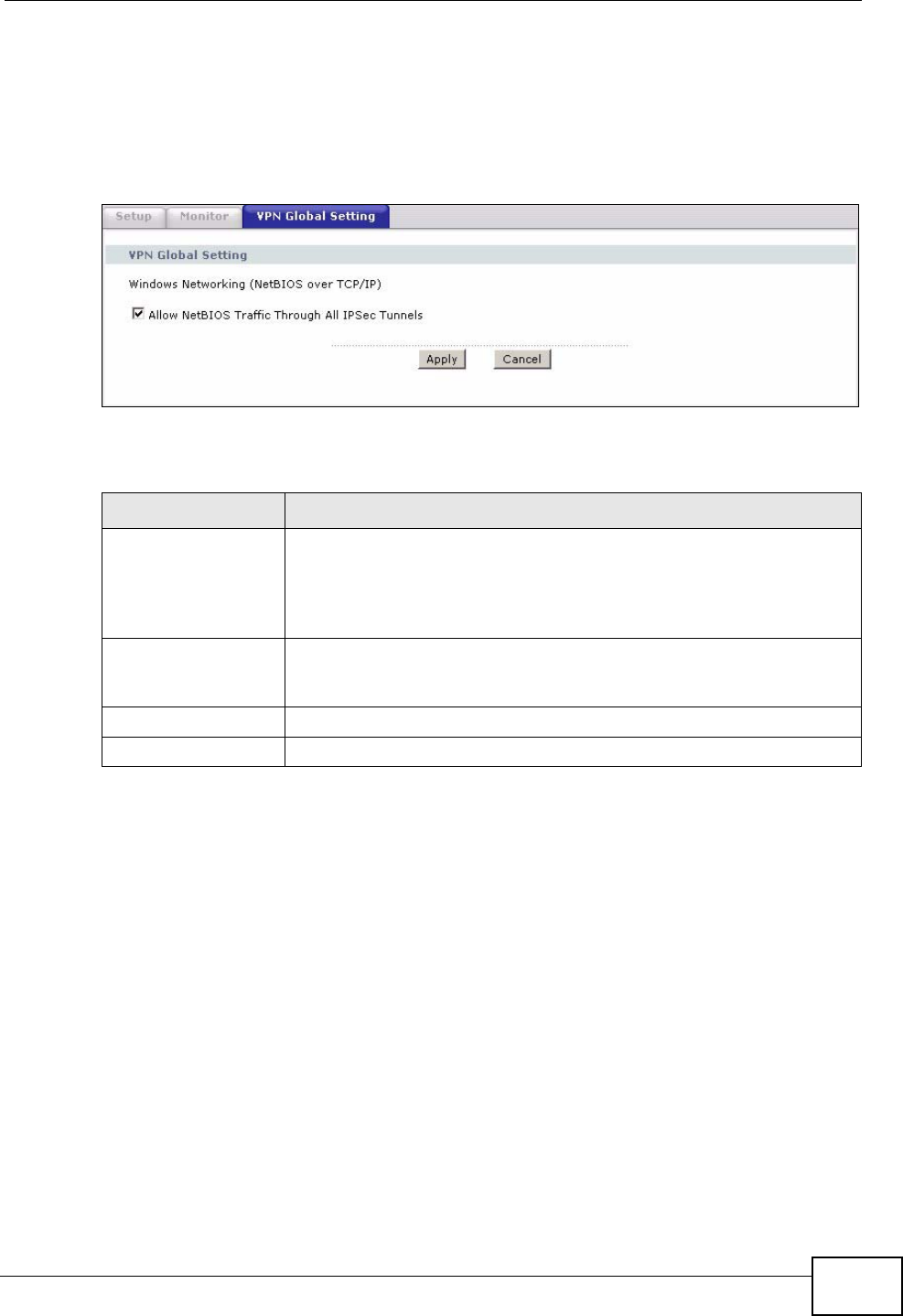
Chapter 14 VPN
P-2612HWU-F1 User’s Guide 273
14.8 Configuring VPN Global Setting
To change your ZyXEL Device’s global settings, click VPN > VPN Global Setting.
The screen appears as shown.
Figure 164 Security > VPN > Global Setting
The following table describes the fields in this screen.
14.9 IPSec VPN Technical Reference
This section provides some technical background information about the topics
covered in this chapter.
Table 83 Security > VPN > Global Setting
LABEL DESCRIPTION
Windows
Networking
(NetBIOS over TCP/
IP)
NetBIOS (Network Basic Input/Output System) are TCP or UDP
packets that enable a computer to find other computers. It may
sometimes be necessary to allow NetBIOS packets to pass through
VPN tunnels in order to allow local computers to find computers on
the remote network and vice versa.
Allow NetBIOS
Traffic Through All
IPSec Tunnels
Select this check box to send NetBIOS packets through the VPN
connection.
Apply Click Apply to save your changes back to the ZyXEL Device.
Cancel Click Cancel to begin configuring this screen afresh.
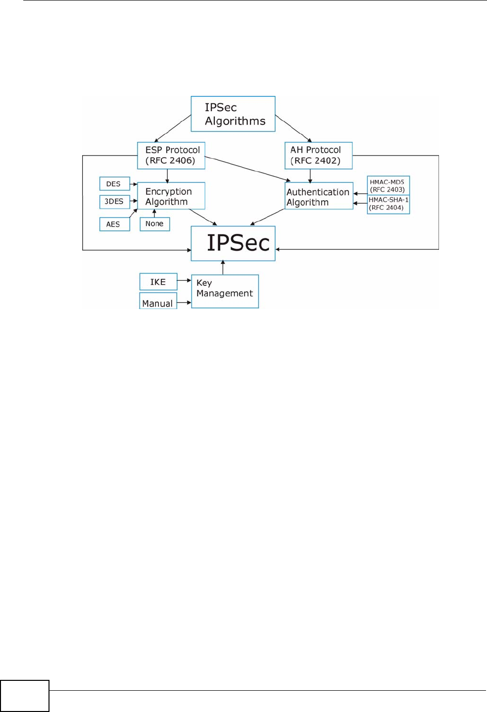
Chapter 14 VPN
P-2612HWU-F1 User’s Guide
274
14.9.1 IPSec Architecture
The overall IPSec architecture is shown as follows.
Figure 165 IPSec Architecture
IPSec Algorithms
The ESP (Encapsulating Security Payload) Protocol (RFC 2406) and AH
(Authentication Header) protocol (RFC 2402) describe the packet formats and the
default standards for packet structure (including implementation algorithms).
The Encryption Algorithm describes the use of encryption techniques such as DES
(Data Encryption Standard) and Triple DES algorithms.
The Authentication Algorithms, HMAC-MD5 (RFC 2403) and HMAC-SHA-1 (RFC
2404, provide an authentication mechanism for the AH and ESP protocols.
Key Management
Key management allows you to determine whether to use IKE (ISAKMP) or
manual key configuration in order to set up a VPN.
14.9.2 IPSec and NAT
Read this section if you are running IPSec on a host computer behind the ZyXEL
Device.
NAT is incompatible with the AH protocol in both Transport and Tunnel mode.
An IPSec VPN using the AH protocol digitally signs the outbound packet, both data
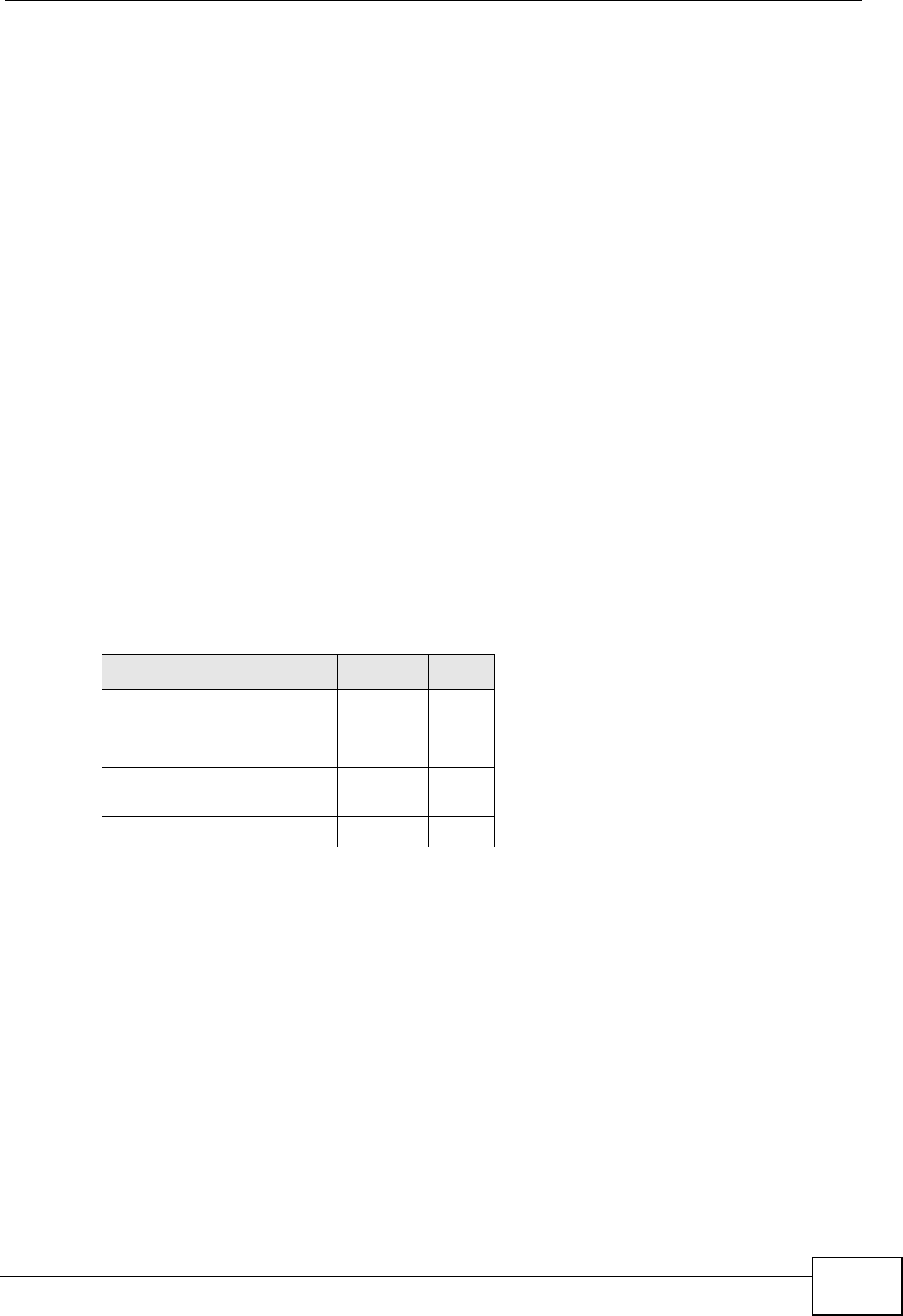
Chapter 14 VPN
P-2612HWU-F1 User’s Guide 275
payload and headers, with a hash value appended to the packet. When using AH
protocol, packet contents (the data payload) are not encrypted.
A NAT device in between the IPSec endpoints will rewrite either the source or
destination address with one of its own choosing. The VPN device at the receiving
end will verify the integrity of the incoming packet by computing its own hash
value, and complain that the hash value appended to the received packet doesn't
match. The VPN device at the receiving end doesn't know about the NAT in the
middle, so it assumes that the data has been maliciously altered.
IPSec using ESP in Tunnel mode encapsulates the entire original packet
(including headers) in a new IP packet. The new IP packet's source address is the
outbound address of the sending VPN gateway, and its destination address is the
inbound address of the VPN device at the receiving end. When using ESP protocol
with authentication, the packet contents (in this case, the entire original packet)
are encrypted. The encrypted contents, but not the new headers, are signed with
a hash value appended to the packet.
Tunnel mode ESP with authentication is compatible with NAT because integrity
checks are performed over the combination of the "original header plus original
payload," which is unchanged by a NAT device.
Transport mode ESP with authentication is not compatible with NAT.
14.9.3 VPN, NAT, and NAT Traversal
NAT is incompatible with the AH protocol in both transport and tunnel mode. An
IPSec VPN using the AH protocol digitally signs the outbound packet, both data
payload and headers, with a hash value appended to the packet, but a NAT device
between the IPSec endpoints rewrites the source or destination address. As a
result, the VPN device at the receiving end finds a mismatch between the hash
value and the data and assumes that the data has been maliciously altered.
NAT is not normally compatible with ESP in transport mode either, but the ZyXEL
Device’s NAT Traversal feature provides a way to handle this. NAT traversal
Table 84 VPN and NAT
SECURITY PROTOCOL MODE NAT
AH Transpor
tN
AH Tunnel N
ESP Transpor
tN
ESP Tunnel Y
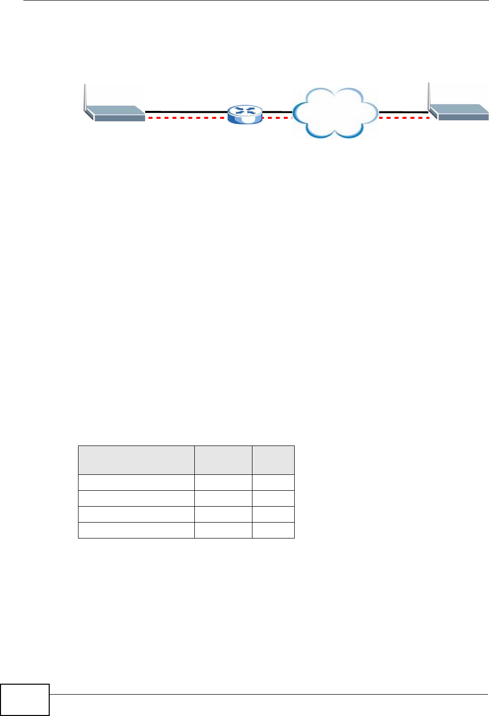
Chapter 14 VPN
P-2612HWU-F1 User’s Guide
276
allows you to set up an IKE SA when there are NAT routers between the two IPSec
routers.
Figure 166 NAT Router Between IPSec Routers
Normally you cannot set up an IKE SA with a NAT router between the two IPSec
routers because the NAT router changes the header of the IPSec packet. NAT
traversal solves the problem by adding a UDP port 500 header to the IPSec
packet. The NAT router forwards the IPSec packet with the UDP port 500 header
unchanged. In Figure 166 on page 276, when IPSec router A tries to establish an
IKE SA, IPSec router B checks the UDP port 500 header, and IPSec routers A and
B build the IKE SA.
For NAT traversal to work, you must:
• Use ESP security protocol (in either transport or tunnel mode).
•Use IKE keying mode.
• Enable NAT traversal on both IPSec endpoints.
• Set the NAT router to forward UDP port 500 to IPSec router A.
Finally, NAT is compatible with ESP in tunnel mode because integrity checks are
performed over the combination of the "original header plus original payload,"
which is unchanged by a NAT device. The compatibility of AH and ESP with NAT in
tunnel and transport modes is summarized in the following table.
Y* - This is supported in the ZyXEL Device if you enable NAT traversal.
Table 85 VPN and NAT
SECURITY
PROTOCOL MODE NAT
AH Transport N
AH Tunnel N
ESP Transport Y*
ESP Tunnel Y
Internet
AB
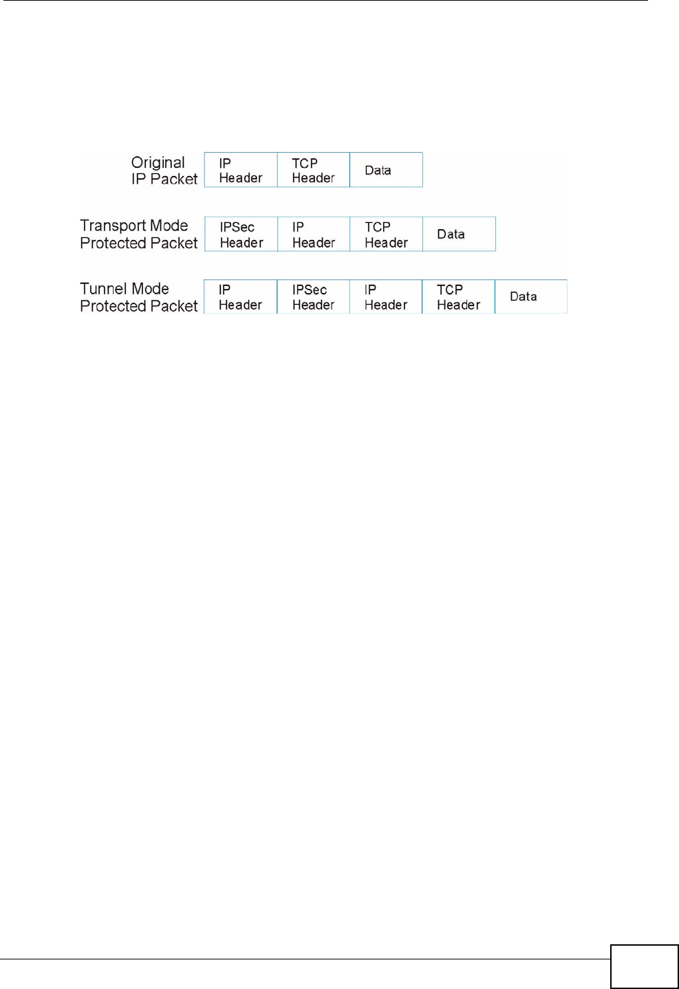
Chapter 14 VPN
P-2612HWU-F1 User’s Guide 277
14.9.4 Encapsulation
The two modes of operation for IPSec VPNs are Transport mode and Tunnel
mode.
Figure 167 Transport and Tunnel Mode IPSec Encapsulation
Transport Mode
Transport mode is used to protect upper layer protocols and only affects the data
in the IP packet. In Transport mode, the IP packet contains the security protocol
(AH or ESP) located after the original IP header and options, but before any upper
layer protocols contained in the packet (such as TCP and UDP).
With ESP, protection is applied only to the upper layer protocols contained in the
packet. The IP header information and options are not used in the authentication
process. Therefore, the originating IP address cannot be verified for integrity
against the data.
With the use of AH as the security protocol, protection is extended forward into
the IP header to verify the integrity of the entire packet by use of portions of the
original IP header in the hashing process.
Tunnel Mode
Tunnel mode encapsulates the entire IP packet to transmit it securely. A Tunnel
mode is required for gateway services to provide access to internal systems.
Tunnel mode is fundamentally an IP tunnel with authentication and encryption.
This is the most common mode of operation. Tunnel mode is required for
gateway to gateway and host to gateway communications. Tunnel mode
communications have two sets of IP headers:
•Outside header: The outside IP header contains the destination IP address of
the VPN gateway.
•Inside header: The inside IP header contains the destination IP address of the
final system behind the VPN gateway. The security protocol appears after the
outer IP header and before the inside IP header.
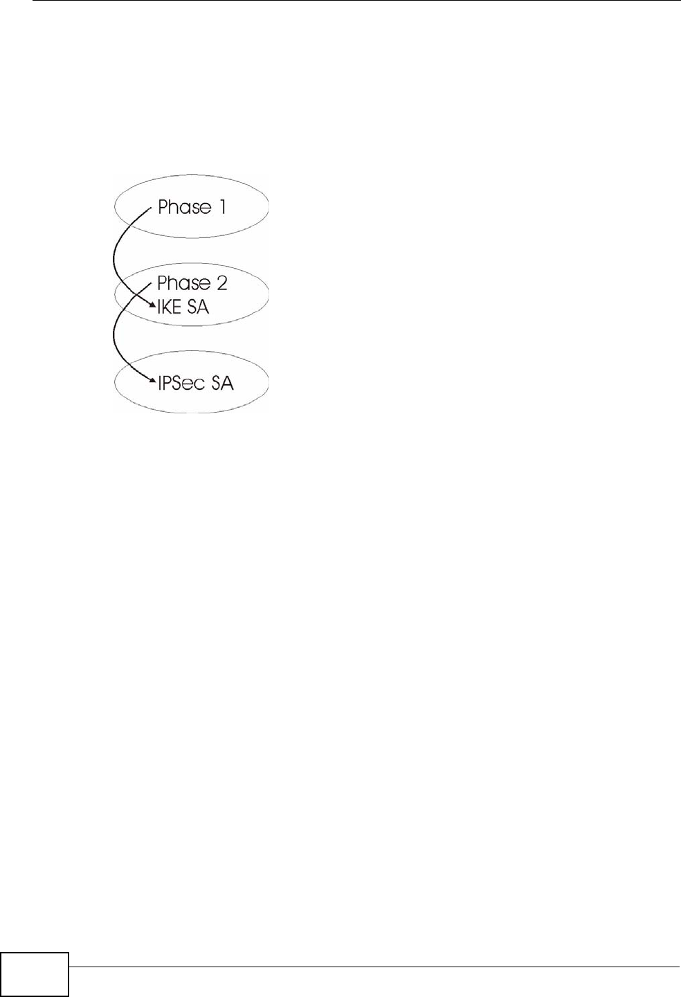
Chapter 14 VPN
P-2612HWU-F1 User’s Guide
278
14.9.5 IKE Phases
There are two phases to every IKE (Internet Key Exchange) negotiation – phase 1
(Authentication) and phase 2 (Key Exchange). A phase 1 exchange establishes an
IKE SA and the second one uses that SA to negotiate SAs for IPSec.
Figure 168 Two Phases to Set Up the IPSec SA
In phase 1 you must:
• Choose a negotiation mode.
• Authenticate the connection by entering a pre-shared key.
• Choose an encryption algorithm.
• Choose an authentication algorithm.
• Choose a Diffie-Hellman public-key cryptography key group (DH1 or DH2).
• Set the IKE SA lifetime. This field allows you to determine how long an IKE SA
should stay up before it times out. An IKE SA times out when the IKE SA lifetime
period expires. If an IKE SA times out when an IPSec SA is already established,
the IPSec SA stays connected.
In phase 2 you must:
• Choose which protocol to use (ESP or AH) for the IKE key exchange.
• Choose an encryption algorithm.
• Choose an authentication algorithm
• Choose whether to enable Perfect Forward Secrecy (PFS) using Diffie-Hellman
public-key cryptography – see Appendix D on page 533. Select None (the
default) to disable PFS.
• Choose Tunnel mode or Transport mode.

Chapter 14 VPN
P-2612HWU-F1 User’s Guide 279
• Set the IPSec SA lifetime. This field allows you to determine how long the IPSec
SA should stay up before it times out. The ZyXEL Device automatically
renegotiates the IPSec SA if there is traffic when the IPSec SA lifetime period
expires. The ZyXEL Device also automatically renegotiates the IPSec SA if both
IPSec routers have keep alive enabled, even if there is no traffic. If an IPSec SA
times out, then the IPSec router must renegotiate the SA the next time
someone attempts to send traffic.
14.9.6 Negotiation Mode
The phase 1 Negotiation Mode you select determines how the Security
Association (SA) will be established for each connection through IKE negotiations.
•Main Mode ensures the highest level of security when the communicating
parties are negotiating authentication (phase 1). It uses 6 messages in three
round trips: SA negotiation, Diffie-Hellman exchange and an exchange of
nonces (a nonce is a random number). This mode features identity protection
(your identity is not revealed in the negotiation).
•Aggressive Mode is quicker than Main Mode because it eliminates several
steps when the communicating parties are negotiating authentication (phase 1).
However the trade-off is that faster speed limits its negotiating power and it also
does not provide identity protection. It is useful in remote access situations
where the address of the initiator is not know by the responder and both parties
want to use pre-shared key authentication.
14.9.7 Keep Alive
When you initiate an IPSec tunnel with keep alive enabled, the ZyXEL Device
automatically renegotiates the tunnel when the IPSec SA lifetime period expires
(see Section 14.9.5 on page 278 for more on the IPSec SA lifetime). In effect, the
IPSec tunnel becomes an “always on” connection after you initiate it. Both IPSec
routers must have a ZyXEL Device-compatible keep alive feature enabled in order
for this feature to work.
If the ZyXEL Device has its maximum number of simultaneous IPSec tunnels
connected to it and they all have keep alive enabled, then no other tunnels can
take a turn connecting to the ZyXEL Device because the ZyXEL Device never drops
the tunnels that are already connected.
When there is outbound traffic with no inbound traffic, the ZyXEL Device
automatically drops the tunnel after two minutes.
14.9.8 Remote DNS Server
In cases where you want to use domain names to access Intranet servers on a
remote network that has a DNS server, you must identify that DNS server. You
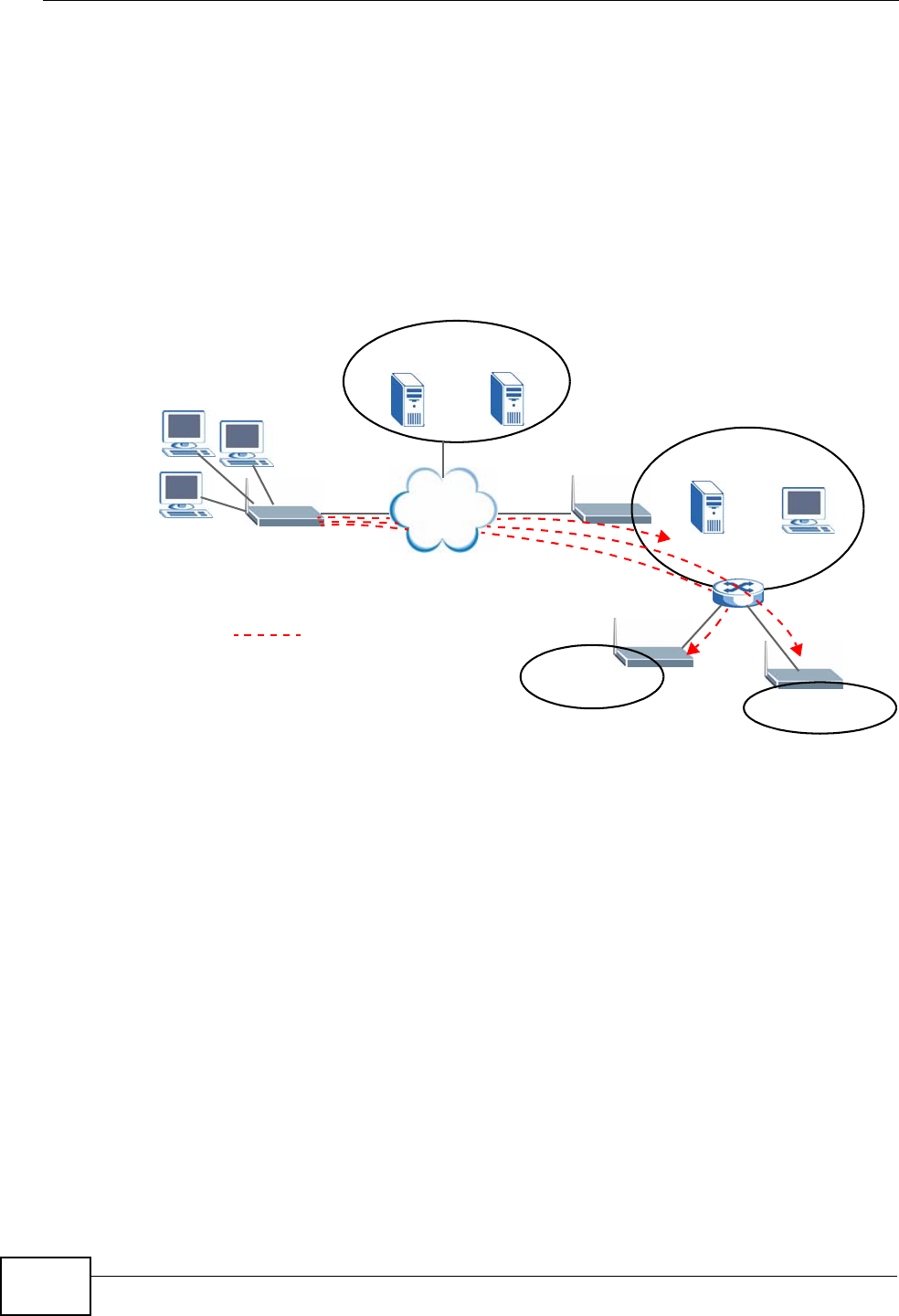
Chapter 14 VPN
P-2612HWU-F1 User’s Guide
280
cannot use DNS servers on the LAN or from the ISP since these DNS servers
cannot resolve domain names to private IP addresses on the remote network
The following figure depicts an example where three VPN tunnels are created from
ZyXEL Device A; one to branch office 2, one to branch office 3 and another to
headquarters. In order to access computers that use private domain names on the
headquarters (HQ) network, the ZyXEL Device at branch office 1 uses the Intranet
DNS server in headquarters. The DNS server feature for VPN does not work with
Windows 2000 or Windows XP.
Figure 169 VPN Host using Intranet DNS Server Example
If you do not specify an Intranet DNS server on the remote network, then the VPN
host must use IP addresses to access the computers on the remote network.
14.9.9 ID Type and Content
With aggressive negotiation mode (seeSection 14.9.6 on page 279), the ZyXEL
Device identifies incoming SAs by ID type and content since this identifying
information is not encrypted. This enables the ZyXEL Device to distinguish
between multiple rules for SAs that connect from remote IPSec routers that have
dynamic WAN IP addresses. Telecommuters can use separate passwords to
simultaneously connect to the ZyXEL Device from IPSec routers with dynamic IP
addresses (seeSection 14.9.12 on page 282 for a telecommuter configuration
example).
Regardless of the ID type and content configuration, the ZyXEL Device does not
allow you to save multiple active rules with overlapping local and remote IP
addresses.
Remote
IPSec Router
HQ
10.1.1.1/200
Intranet DNS
10.1.1.10
ISP DNS Servers
212.54.64.170 212.54.54.171
Internet
LAN
DNS:212.54.64.170
212.54.64.171
A
VPN DNS: 10.1.1.10
= VPN Tunnel
2
192.168.1.1/50
3
172.16.1.1/50
1
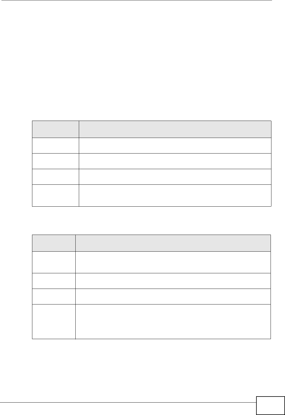
Chapter 14 VPN
P-2612HWU-F1 User’s Guide 281
With main mode (seeSection 14.9.6 on page 279), the ID type and content are
encrypted to provide identity protection. In this case the ZyXEL Device can only
distinguish between up to 12 different incoming SAs that connect from remote
IPSec routers that have dynamic WAN IP addresses. The ZyXEL Device can
distinguish up to 12 incoming SAs because you can select between three
encryption algorithms (DES, 3DES and AES), two authentication algorithms (MD5
and SHA1) and two key groups (DH1 and DH2) when you configure a VPN rule
(seeSection 14.4 on page 264). The ID type and content act as an extra level of
identification for incoming SAs.
The type of ID can be a domain name, an IP address or an e-mail address. The
content is the IP address, domain name, or e-mail address.
14.9.9.1 ID Type and Content Examples
Two IPSec routers must have matching ID type and content configuration in order
to set up a VPN tunnel.
Table 86 Local ID Type and Content Fields
LOCAL ID
TYPE= CONTENT=
IP Type the IP address of your computer or leave the field blank to have
the ZyXEL Device automatically use its own IP address.
DNS Type a domain name (up to 31 characters) by which to identify this
ZyXEL Device.
E-mail Type an e-mail address (up to 31 characters) by which to identify this
ZyXEL Device.
The domain name or e-mail address that you use in the Content field is
used for identification purposes only and does not need to be a real
domain name or e-mail address.
Table 87 Peer ID Type and Content Fields
PEER ID
TYPE= CONTENT=
IP Type the IP address of the computer with which you will make the VPN
connection or leave the field blank to have the ZyXEL Device
automatically use the address in the Secure Gateway Address field.
DNS Type a domain name (up to 31 characters) by which to identify the
remote IPSec router.
E-mail Type an e-mail address (up to 31 characters) by which to identify the
remote IPSec router.
The domain name or e-mail address that you use in the Content field is
used for identification purposes only and does not need to be a real
domain name or e-mail address. The domain name also does not have to
match the remote router’s IP address or what you configure in the
Secure Gateway Address field below.
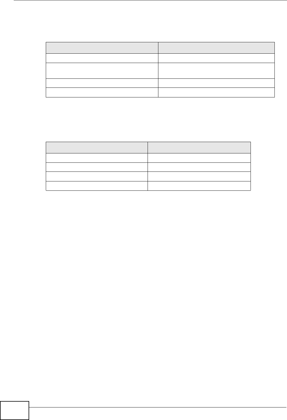
Chapter 14 VPN
P-2612HWU-F1 User’s Guide
282
The two ZyXEL Devices in this example can complete negotiation and establish a
VPN tunnel.
The two ZyXEL Devices in this example cannot complete their negotiation because
ZyXEL Device B’s Local ID type is IP, but ZyXEL Device A’s Peer ID type is set
to E-mail. An “ID mismatched” message displays in the IPSEC LOG.
14.9.10 Pre-Shared Key
A pre-shared key identifies a communicating party during a phase 1 IKE
negotiation (see Section 14.9.5 on page 278 for more on IKE phases). It is called
“pre-shared” because you have to share it with another party before you can
communicate with them over a secure connection.
14.9.11 Diffie-Hellman (DH) Key Groups
Diffie-Hellman (DH) is a public-key cryptography protocol that allows two parties
to establish a shared secret over an unsecured communications channel. Diffie-
Hellman is used within IKE SA setup to establish session keys. 768-bit (Group 1 -
DH1) and 1024-bit (Group 2 – DH2) Diffie-Hellman groups are supported. Upon
completion of the Diffie-Hellman exchange, the two peers have a shared secret,
but the IKE SA is not authenticated. For authentication, use pre-shared keys.
14.9.12 Telecommuter VPN/IPSec Examples
The following examples show how multiple telecommuters can make VPN
connections to a single ZyXEL Device at headquarters. The telecommuters use
IPSec routers with dynamic WAN IP addresses. The ZyXEL Device at headquarters
has a static public IP address.
Table 88 Matching ID Type and Content Configuration Example
ZYXEL DEVICE A ZYXEL DEVICE B
Local ID type: E-mail Local ID type: IP
Local ID content:
tom@yourcompany.com Local ID content: 1.1.1.2
Peer ID type: IP Peer ID type: E-mail
Peer ID content: 1.1.1.2 Peer ID content: tom@yourcompany.com
Table 89 Mismatching ID Type and Content Configuration Example
ZYXEL DEVICE A ZYXEL DEVICE B
Local ID type: IP Local ID type: IP
Local ID content: 1.1.1.10 Local ID content: 1.1.1.10
Peer ID type: E-mail Peer ID type: IP
Peer ID content: aa@yahoo.com Peer ID content: N/A
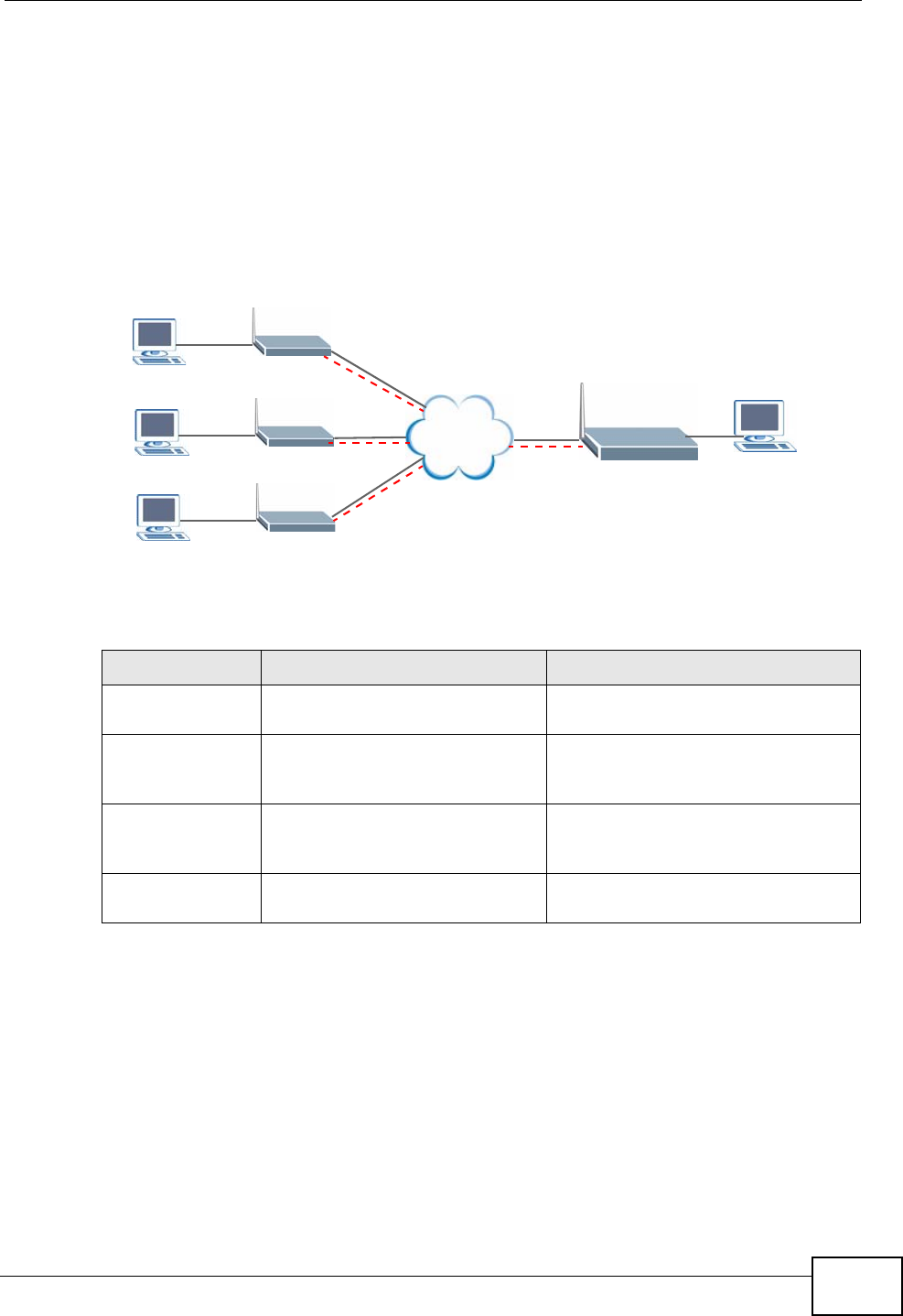
Chapter 14 VPN
P-2612HWU-F1 User’s Guide 283
14.9.12.1 Telecommuters Sharing One VPN Rule Example
See the following figure and table for an example configuration that allows
multiple telecommuters (A, B and C in the figure) to use one VPN rule to
simultaneously access a ZyXEL Device at headquarters (HQ in the figure). The
telecommuters do not have domain names mapped to the WAN IP addresses of
their IPSec routers. The telecommuters must all use the same IPSec parameters
but the local IP addresses (or ranges of addresses) should not overlap.
Figure 170 Telecommuters Sharing One VPN Rule Example
14.9.12.2 Telecommuters Using Unique VPN Rules Example
In this example the telecommuters (A, B and C in the figure) use IPSec routers
with domain names that are mapped to their dynamic WAN IP addresses (use
Dynamic DNS to do this).
With aggressive negotiation mode (see Section 14.9.6 on page 279), the ZyXEL
Device can use the ID types and contents to distinguish between VPN rules.
Telecommuters can each use a separate VPN rule to simultaneously access a
ZyXEL Device at headquarters. They can use different IPSec parameters. The local
IP addresses (or ranges of addresses) of the rules configured on the ZyXEL Device
Table 90 Telecommuters Sharing One VPN Rule Example
FIELDS TELECOMMUTERS HEADQUARTERS
My IP Address: 0.0.0.0 (dynamic IP address
assigned by the ISP) Public static IP address
Secure Gateway
IP Address: Public static IP address 0.0.0.0 With this IP address
only the telecommuter can initiate
the IPSec tunnel.
Local IP Address: Telecommuter A: 192.168.2.12
Telecommuter B: 192.168.3.2
Telecommuter C: 192.168.4.15
192.168.1.10
Remote IP
Address: 192.168.1.10 0.0.0.0 (N/A)
LAN
192.168.2.12
LAN
192.168.3.2
LAN
192.168.4.15
A
B
C
LAN
192.168.1.10
HQ
Internet
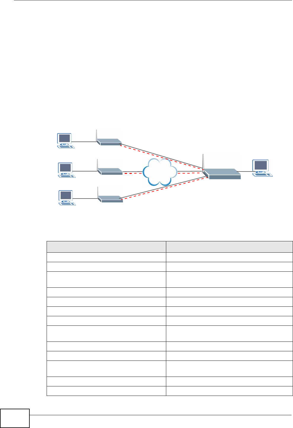
Chapter 14 VPN
P-2612HWU-F1 User’s Guide
284
at headquarters can overlap. The local IP addresses of the rules configured on the
telecommuters’ IPSec routers should not overlap.
See the following table and figure for an example where three telecommuters
each use a different VPN rule for a VPN connection with a ZyXEL Device located at
headquarters. The ZyXEL Device at headquarters (HQ in the figure) identifies
each incoming SA by its ID type and content and uses the appropriate VPN rule to
establish the VPN connection.
The ZyXEL Device at headquarters can also initiate VPN connections to the
telecommuters since it can find the telecommuters by resolving their domain
names.
Figure 171 Telecommuters Using Unique VPN Rules Example
Table 91 Telecommuters Using Unique VPN Rules Example
TELECOMMUTERS HEADQUARTERS
All Telecommuter Rules: All Headquarters Rules:
My IP Address 0.0.0.0 My IP Address: bigcompanyhq.com
Secure Gateway Address:
bigcompanyhq.com Local IP Address: 192.168.1.10
Remote IP Address: 192.168.1.10 Local ID Type: E-mail
Peer ID Type: E-mail Local ID Content: bob@bigcompanyhq.com
Peer ID Content: bob@bigcompanyhq.com
Telecommuter A
(telecommutera.dydns.org) Headquarters ZyXEL Device Rule 1:
Local ID Type: IP Peer ID Type: IP
Local ID Content: 192.168.2.12 Peer ID Content: 192.168.2.12
Local IP Address: 192.168.2.12 Secure Gateway Address:
telecommuter1.com
Remote Address 192.168.2.12
LAN
192.168.2.12
LAN
192.168.3.2
LAN
192.168.4.15
A
B
C
LAN
192.168.1.10
HQ
Internet
Chapter 14 VPN
P-2612HWU-F1 User’s Guide 285
Telecommuter B
(telecommuterb.dydns.org) Headquarters ZyXEL Device Rule 2:
Local ID Type: DNS Peer ID Type: DNS
Local ID Content: telecommuterb.com Peer ID Content: telecommuterb.com
Local IP Address: 192.168.3.2 Secure Gateway Address:
telecommuterb.com
Remote Address 192.168.3.2
Telecommuter C
(telecommuterc.dydns.org) Headquarters ZyXEL Device Rule 3:
Local ID Type: E-mail Peer ID Type: E-mail
Local ID Content: myVPN@myplace.com Peer ID Content: myVPN@myplace.com
Local IP Address: 192.168.4.15 Secure Gateway Address:
telecommuterc.com
Remote Address 192.168.4.15
Table 91 Telecommuters Using Unique VPN Rules Example (continued)
TELECOMMUTERS HEADQUARTERS

Chapter 14 VPN
P-2612HWU-F1 User’s Guide
286

P-2612HWU-F1 User’s Guide 287
CHAPTER 15
Certificates
15.1 Overview
The ZyXEL Device can use certificates (also called digital IDs) to authenticate
users. Certificates are based on public-private key pairs. A certificate contains the
certificate owner’s identity and public key. Certificates provide a way to exchange
public keys for use in authentication.
15.1.1 What You Can Do in the Certificate Screens
•Use the My Certificate screens (see Section 15.2 on page 291) to generate and
export self-signed certificates or certification requests and import the ZyXEL
Device’s CA-signed certificates.
•Use the Trusted CA screens (see Section 15.5 on page 300) to save the
certificates of trusted CAs to the ZyXEL Device. You can also export the
certificates to a computer.
•Use the Trusted Remote Hosts screens (see Section 15.8 on page 306) to
import self-signed certificates from trusted remote hosts.
15.1.2 What You Need to Know About Certificates
Certification Authorities
A Certification Authority (CA) issues certificates and guarantees the identity of
each certificate owner. There are commercial certification authorities like
CyberTrust or VeriSign and government certification authorities. You can use the
ZyXEL Device to generate certification requests that contain identifying
information and public keys and then send the certification requests to a
certification authority.
Public and Private Keys
When using public-key cryptology for authentication, each host has two keys. One
key is public and can be made openly available; the other key is private and must
be kept secure. Public-key encryption in general works as follows.

Chapter 15 Certificates
P-2612HWU-F1 User’s Guide
288
1Tim wants to send a private message to Jenny. Tim generates a public-private key
pair. What is encrypted with one key can only be decrypted using the other.
2Tim keeps the private key and makes the public key openly available.
3Tim uses his private key to encrypt the message and sends it to Jenny.
4Jenny receives the message and uses Tim’s public key to decrypt it.
5Additionally, Jenny uses her own private key to encrypt a message and Tim uses
Jenny’s public key to decrypt the message.
The ZyXEL Device uses certificates based on public-key cryptology to authenticate
users attempting to establish a connection. The method used to secure the data
that you send through an established connection depends on the type of
connection. For example, a VPN tunnel might use the triple DES encryption
algorithm.
The certification authority uses its private key to sign certificates. Anyone can then
use the certification authority’s public key to verify the certificates.
Certification Path
A certification path is the hierarchy of certification authority certificates that
validate a certificate. The ZyXEL Device does not trust a certificate if any
certificate on its path has expired or been revoked.
Certificate Directory Servers
Certification authorities maintain directory servers with databases of valid and
revoked certificates. A directory of certificates that have been revoked before the
scheduled expiration is called a CRL (Certificate Revocation List). The ZyXEL
Device can check a peer’s certificate against a directory server’s list of revoked
certificates. The framework of servers, software, procedures and policies that
handles keys is called PKI (public-key infrastructure).
Advantages of Certificates
Certificates offer the following benefits.
• The ZyXEL Device only has to store the certificates of the certification
authorities that you decide to trust, no matter how many devices you need to
authenticate.
• Key distribution is simple and very secure since you can freely distribute public
keys and you never need to transmit private keys.
Chapter 15 Certificates
P-2612HWU-F1 User’s Guide 289
Self-signed Certificates
You can have the ZyXEL Device act as a certification authority and sign its own
certificates.
15.1.3 Verifying a Certificate
Before you import a trusted CA or trusted remote host certificate into the ZyXEL
Device, you should verify that you have the actual certificate. This is especially
true of trusted CA certificates since the ZyXEL Device also trusts any valid
certificate signed by any of the imported trusted CA certificates.
You can use a certificate’s fingerprint to verify it. A certificate’s fingerprint is a
message digest calculated using the MD5 or SHA1 algorithms. The following
procedure describes how to check a certificate’s fingerprint to verify that you have
the actual certificate.
1Browse to where you have the certificate saved on your computer.
2Make sure that the certificate has a “.cer” or “.crt” file name extension.
Figure 172 Certificates on Your Computer
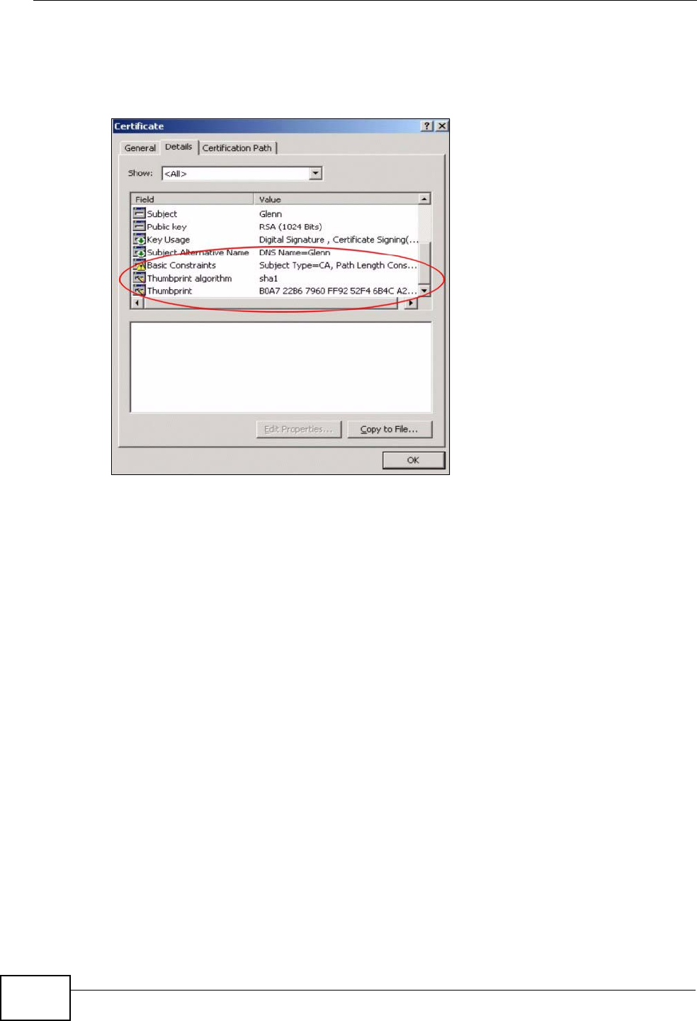
Chapter 15 Certificates
P-2612HWU-F1 User’s Guide
290
3Double-click the certificate’s icon to open the Certificate window. Click the
Details tab and scroll down to the Thumbprint Algorithm and Thumbprint
fields.
Figure 173 Certificate Details
4Use a secure method to verify that the certificate owner has the same information
in the Thumbprint Algorithm and Thumbprint fields. The secure method may
very based on your situation. Possible examples would be over the telephone or
through an HTTPS connection.
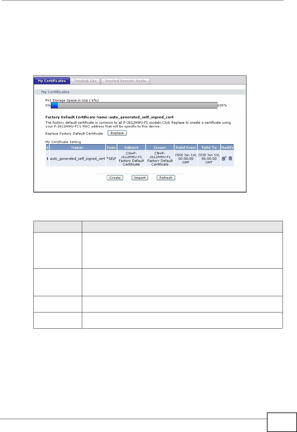
Chapter 15 Certificates
P-2612HWU-F1 User’s Guide 291
15.2 My Certificates
Click Security > Certificates > My Certificates to open the My Certificates
screen. This is the ZyXEL Device’s summary list of certificates and certification
requests. Certificates display in black and certification requests display in gray.
Figure 174 Security > Certificates > My Certificates
The following table describes the labels in this screen.
Table 92 Security > Certificates > My Certificates
LABEL DESCRIPTION
PKI Storage
Space in Use This bar displays the percentage of the ZyXEL Device’s PKI storage
space that is currently in use. The bar turns from green to red when the
maximum is being approached. When the bar is red, you should
consider deleting expired or unnecessary certificates before adding
more certificates.
Replace This button displays when the ZyXEL Device has the factory default certificate.
The factory default certificate is common to all devices of this model. ZyXEL
recommends that you use this button to replace the factory default certificate with
one that uses your ZyXEL Device's MAC address.
# This field displays the certificate index number. The certificates are
listed in alphabetical order.
Name This field displays the name used to identify this certificate. It is
recommended that you give each certificate a unique name.
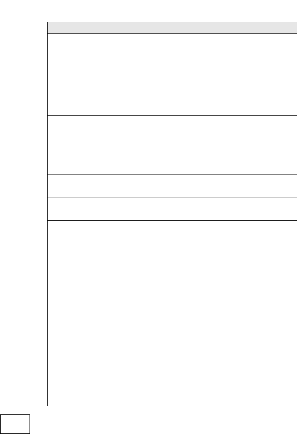
Chapter 15 Certificates
P-2612HWU-F1 User’s Guide
292
Type This field displays what kind of certificate this is.
REQ represents a certification request and is not yet a valid certificate.
Send a certification request to a certification authority, which then
issues a certificate. Use the My Certificate Import screen to import
the certificate and replace the request.
SELF represents a self-signed certificate.
*SELF represents the default self-signed certificate, which the ZyXEL
Device uses to sign imported trusted remote host certificates.
CERT represents a certificate issued by a certification authority.
Subject This field displays identifying information about the certificate’s owner,
such as CN (Common Name), OU (Organizational Unit or department),
O (Organization or company) and C (Country). It is recommended that
each certificate have unique subject information.
Issuer This field displays identifying information about the certificate’s issuing
certification authority, such as a common name, organizational unit or
department, organization or company and country. With self-signed
certificates, this is the same information as in the Subject field.
Valid From This field displays the date that the certificate becomes applicable. The
text displays in red and includes a Not Yet Valid! message if the
certificate has not yet become applicable.
Valid To This field displays the date that the certificate expires. The text displays
in red and includes an Expiring! or Expired! message if the certificate is
about to expire or has already expired.
Modify Click the Edit icon to open a screen with an in-depth list of information
about the certificate.
Click the Remove icon to remove the certificate. A window displays
asking you to confirm that you want to delete the certificate.
You cannot delete a certificate that one or more features is configured
to use.
Do the following to delete a certificate that shows *SELF in the Type
field.
1. Make sure that no other features, such as HTTPS, VPN, SSH are
configured to use the *SELF certificate.
2. Click the Edit icon next to another self-signed certificate (see the
description on the Create button if you need to create a self-signed
certificate).
3. Select the Default self-signed certificate which signs the
imported remote host certificates check box.
4. Click Apply to save the changes and return to the My Certificates
screen.
5. The certificate that originally showed *SELF displays SELF and you
can delete it now.
Note that subsequent certificates move up by one when you take this
action
Table 92 Security > Certificates > My Certificates (continued)
LABEL DESCRIPTION

Chapter 15 Certificates
P-2612HWU-F1 User’s Guide 293
15.3 My Certificate Details
Click Security > Certificates > My Certificates to open the My Certificates
screen (see Figure 174 on page 291). Click the edit icon to open the My
Certificate Details screen. Use this screen to view in-depth certificate
information and change the certificate’s name.
Create Click Create to go to the screen where you can have the ZyXEL Device
generate a certificate or a certification request.
Import Click Import to open a screen where you can save the certificate that
you have enrolled from a certification authority from your computer to
the ZyXEL Device.
Refresh Click Refresh to display the current validity status of the certificates.
Table 92 Security > Certificates > My Certificates (continued)
LABEL DESCRIPTION
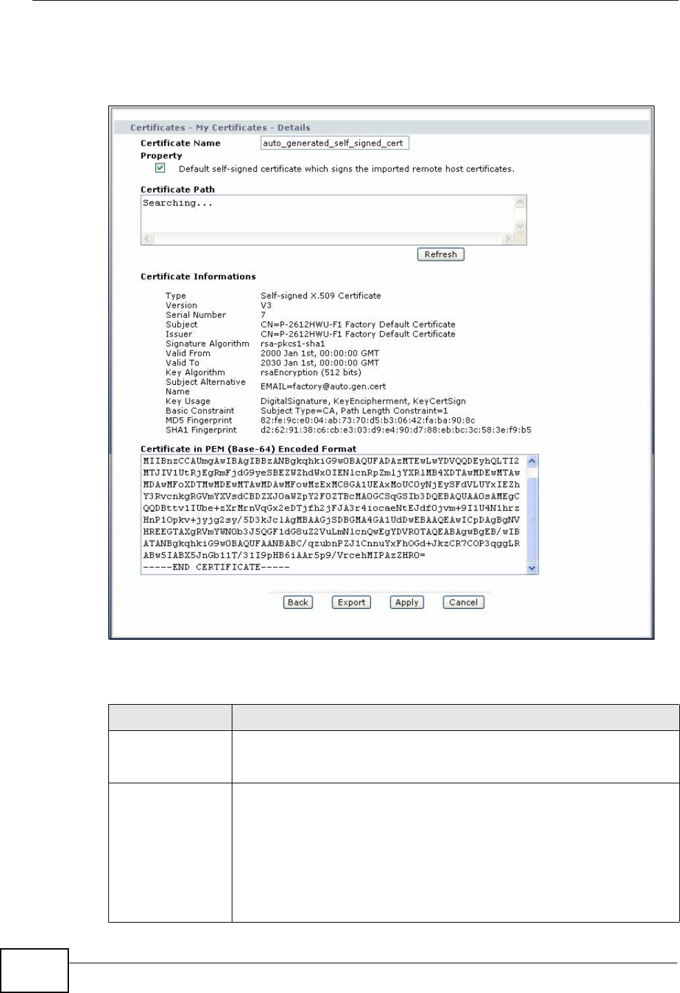
Chapter 15 Certificates
P-2612HWU-F1 User’s Guide
294
If it is a self-signed certificate, you can also set the ZyXEL Device to use the
certificate to sign the imported trusted remote host certificates.
Figure 175 Security > Certificates > My Certificates > Details
The following table describes the labels in this screen.
Table 93 Security > Certificates > My Certificates > Details
LABEL DESCRIPTION
Certificate Name This field displays the identifying name of this certificate. If you want
to change the name, type up to 31 characters to identify this
certificate. You may use any character (not including spaces).
Property
Default self-
signed certificate
which signs the
imported remote
host certificates.
Select this check box to have the ZyXEL Device use this certificate to
sign the trusted remote host certificates that you import to the ZyXEL
Device. This check box is only available with self-signed certificates.
If this check box is already selected, you cannot clear it in this screen,
you must select this check box in another self-signed certificate’s
details screen. This automatically clears the check box in the details
screen of the certificate that was previously set to sign the imported
trusted remote host certificates.
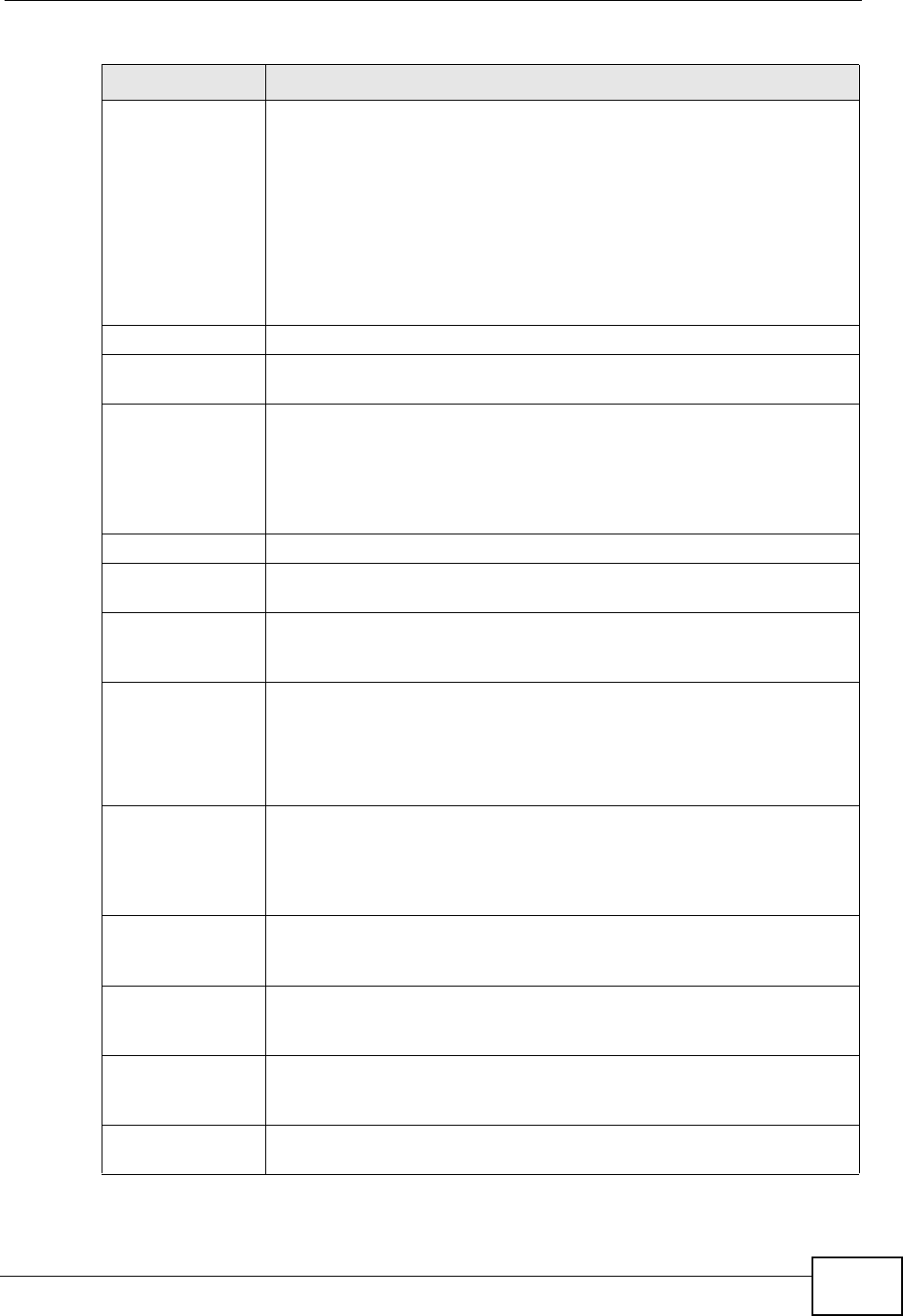
Chapter 15 Certificates
P-2612HWU-F1 User’s Guide 295
Certification Path Click the Refresh button to have this read-only text box display the
hierarchy of certification authorities that validate the certificate (and
the certificate itself).
If the issuing certification authority is one that you have imported as
a trusted certification authority, it may be the only certification
authority in the list (along with the certificate itself). If the certificate
is a self-signed certificate, the certificate itself is the only one in the
list. The ZyXEL Device does not trust the certificate and displays “Not
trusted” in this field if any certificate on the path has expired or been
revoked.
Refresh Click Refresh to display the certification path.
Certificate
Information These read-only fields display detailed information about the
certificate.
Type This field displays general information about the certificate. CA-signed
means that a Certification Authority signed the certificate. Self-signed
means that the certificate’s owner signed the certificate (not a
certification authority). “X.509” means that this certificate was
created and signed according to the ITU-T X.509 recommendation
that defines the formats for public-key certificates.
Version This field displays the X.509 version number.
Serial Number This field displays the certificate’s identification number given by the
certification authority or generated by the ZyXEL Device.
Subject This field displays information that identifies the owner of the
certificate, such as Common Name (CN), Organizational Unit (OU),
Organization (O) and Country (C).
Issuer This field displays identifying information about the certificate’s
issuing certification authority, such as Common Name, Organizational
Unit, Organization and Country.
With self-signed certificates, this is the same as the Subject Name
field.
Signature
Algorithm This field displays the type of algorithm that was used to sign the
certificate. The ZyXEL Device uses rsa-pkcs1-sha1 (RSA public-
private key encryption algorithm and the SHA1 hash algorithm).
Some certification authorities may use rsa-pkcs1-md5 (RSA public-
private key encryption algorithm and the MD5 hash algorithm).
Valid From This field displays the date that the certificate becomes applicable.
The text displays in red and includes a Not Yet Valid! message if the
certificate has not yet become applicable.
Valid To This field displays the date that the certificate expires. The text
displays in red and includes an Expiring! or Expired! message if the
certificate is about to expire or has already expired.
Key Algorithm This field displays the type of algorithm that was used to generate the
certificate’s key pair (the ZyXEL Device uses RSA encryption) and the
length of the key set in bits (1024 bits for example).
Subject
Alternative Name This field displays the certificate owner‘s IP address (IP), domain
name (DNS) or e-mail address (EMAIL).
Table 93 Security > Certificates > My Certificates > Details (continued)
LABEL DESCRIPTION
Chapter 15 Certificates
P-2612HWU-F1 User’s Guide
296
You can only import a certificate that matches a corresponding certification
request that was generated by the ZyXEL Device (the certification request
contains the private key). The certificate you import replaces the corresponding
request in the My Certificates screen.
One exception is that you can import a PKCS#12 format certificate without a
corresponding certification request since the certificate includes the private key.
Note: Remove any spaces from the certificate’s filename before you import it.
Certificate File Formats
The certification authority certificate that you want to import has to be in one of
these file formats:
Key Usage This field displays for what functions the certificate’s key can be used.
For example, “DigitalSignature” means that the key can be used to
sign certificates and “KeyEncipherment” means that the key can be
used to encrypt text.
Basic Constraint This field displays general information about the certificate. For
example, Subject Type=CA means that this is a certification
authority’s certificate and “Path Length Constraint=1” means that
there can only be one certification authority in the certificate’s path.
MD5 Fingerprint This is the certificate’s message digest that the ZyXEL Device
calculated using the MD5 algorithm.
SHA1 Fingerprint This is the certificate’s message digest that the ZyXEL Device
calculated using the SHA1 algorithm.
Certificate in PEM
(Base-64)
Encoded Format
This read-only text box displays the certificate or certification request
in Privacy Enhanced Mail (PEM) format. PEM uses 64 ASCII characters
to convert the binary certificate into a printable form.
You can copy and paste a certification request into a certification
authority’s web page, an e-mail that you send to the certification
authority or a text editor and save the file on a management
computer for later manual enrollment.
You can copy and paste a certificate into an e-mail to send to friends
or colleagues or you can copy and paste a certificate into a text editor
and save the file on a management computer for later distribution
(via floppy disk for example).
Back Click Back to return to the previous screen.
Export Click this button and then Save in the File Download screen. The
Save As screen opens, browse to the location that you want to use
and click Save.
Apply Click Apply to save your changes back to the ZyXEL Device. You can
only change the name, except in the case of a self-signed certificate,
which you can also set to be the default self-signed certificate that
signs the imported trusted remote host certificates.
Cancel Click Cancel to quit and return to the My Certificates screen.
Table 93 Security > Certificates > My Certificates > Details (continued)
LABEL DESCRIPTION
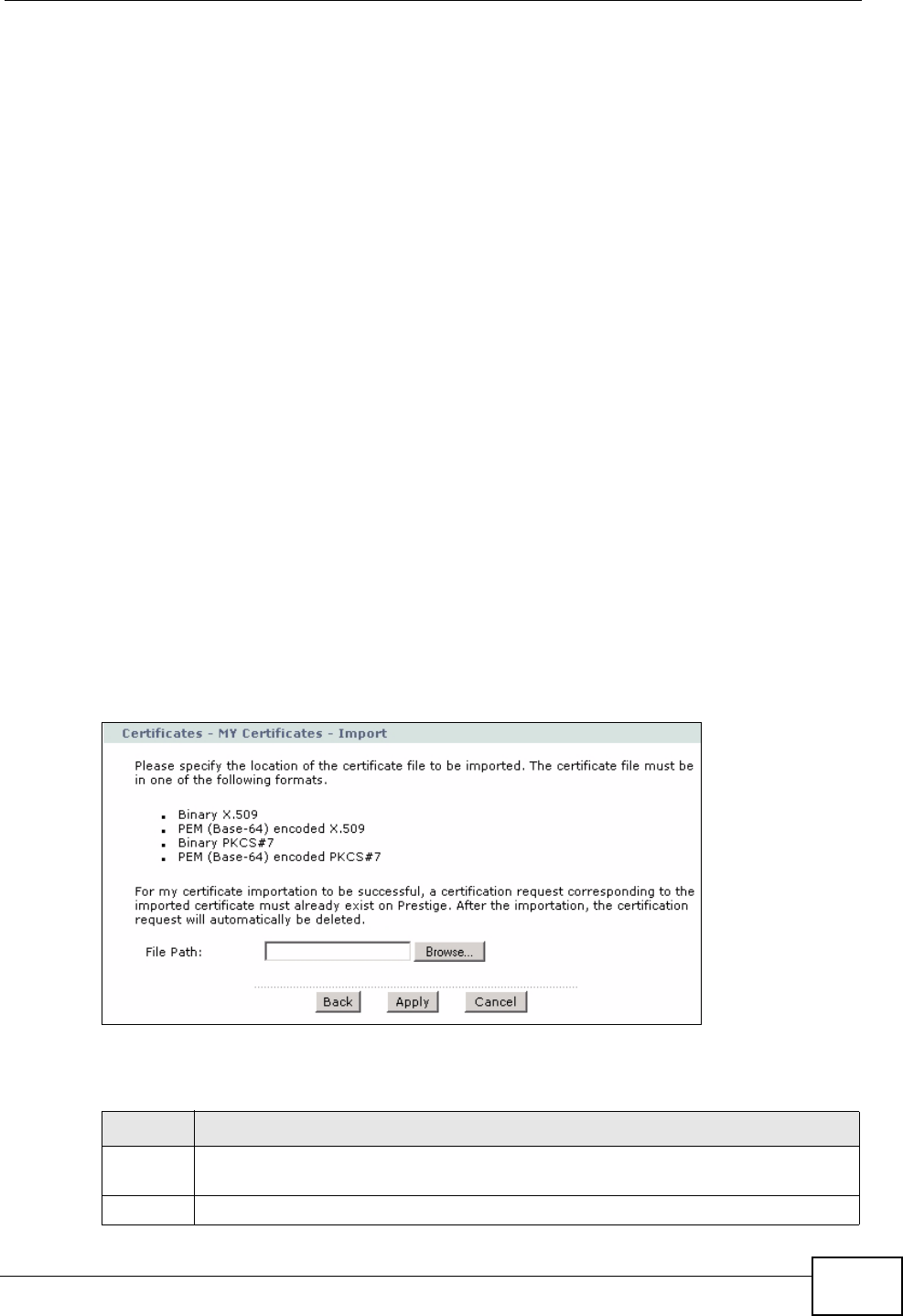
Chapter 15 Certificates
P-2612HWU-F1 User’s Guide 297
• Binary X.509: This is an ITU-T recommendation that defines the formats for
X.509 certificates.
• PEM (Base-64) encoded X.509: This Privacy Enhanced Mail format uses 64
ASCII characters to convert a binary X.509 certificate into a printable form.
• Binary PKCS#7: This is a standard that defines the general syntax for data
(including digital signatures) that may be encrypted. The ZyXEL Device
currently allows the importation of a PKS#7 file that contains a single
certificate.
• PEM (Base-64) encoded PKCS#7: This Privacy Enhanced Mail (PEM) format uses
64 ASCII characters to convert a binary PKCS#7 certificate into a printable
form.
• Binary PKCS#12: This is a format for transferring public key and private key
certificates. The private key in a PKCS #12 file is within a password-encrypted
envelope. The file’s password is not connected to your certificate’s public or
private passwords. Exporting a PKCS #12 file creates this and you must provide
it to decrypt the contents when you import the file into the ZyXEL Device.
Note: Be careful not to convert a binary file to text during the transfer process. It is
easy for this to occur since many programs use text files by default.
15.3.1 Using the My Certificate Import Screen
Click Security > Certificates > My Certificates and then Import to open the
My Certificate Import screen. Follow the instructions in this screen to save an
existing certificate to the ZyXEL Device.
Figure 176 Security > Certificates > My Certificates > Import
The following table describes the labels in this screen.
Table 94 Security > Certificates > My Certificates > Import
LABEL DESCRIPTION
File Path Type in the location of the file you want to upload in this field or click Browse
to find it.
Browse Click Browse to find the certificate file you want to upload.
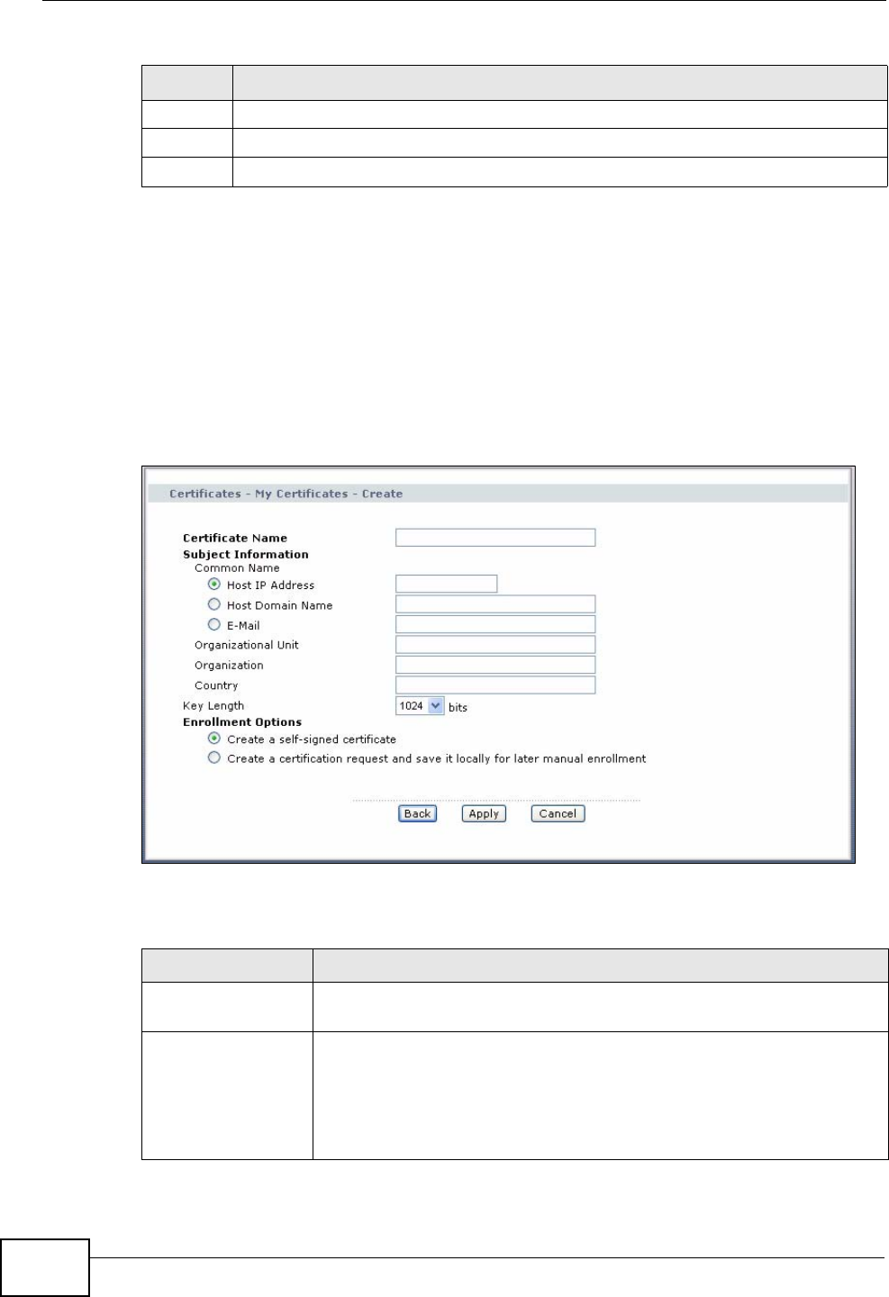
Chapter 15 Certificates
P-2612HWU-F1 User’s Guide
298
15.4 My Certificate Create
Click Security > Certificates > My Certificates > Create to open the My
Certificate Create screen. Use this screen to have the ZyXEL Device create a
self-signed certificate, enroll a certificate with a certification authority or generate
a certification request.
Figure 177 Security > Certificates > My Certificate Create
The following table describes the labels in this screen.
Back Click Back to return to the previous screen.
Apply Click Apply to save the certificate on the ZyXEL Device.
Cancel Click Cancel to clear your settings.
Table 94 Security > Certificates > My Certificates > Import
LABEL DESCRIPTION
Table 95 Security > Certificates > My Certificates > Create
LABEL DESCRIPTION
Certificate Name Type up to 31 ASCII characters (not including spaces) to identify this
certificate.
Subject
Information Use these fields to record information that identifies the owner of the
certificate. You do not have to fill in every field, although the
Common Name is mandatory. The certification authority may add
fields (such as a serial number) to the subject information when it
issues a certificate. It is recommended that each certificate have
unique subject information.
Chapter 15 Certificates
P-2612HWU-F1 User’s Guide 299
After you click Apply in the My Certificate Create screen, you see a screen that
tells you the ZyXEL Device is generating the self-signed certificate or certification
request.
After the ZyXEL Device successfully enrolls a certificate or generates a certification
request or a self-signed certificate, you see a screen with a Return button that
takes you back to the My Certificates screen.
If you configured the My Certificate Create screen to have the ZyXEL Device
enroll a certificate and the certificate enrollment is not successful, you see a
screen with a Return button that takes you back to the My Certificate Create
Common Name Select a radio button to identify the certificate’s owner by IP address,
domain name or e-mail address. Type the IP address (in dotted
decimal notation), domain name or e-mail address in the field
provided. The domain name or e-mail address can be up to 31 ASCII
characters. The domain name or e-mail address is for identification
purposes only and can be any string.
Organizational Unit Type up to 127 characters to identify the organizational unit or
department to which the certificate owner belongs. You may use any
character, including spaces, but the ZyXEL Device drops trailing
spaces.
Organization Type up to 127 characters to identify the company or group to which
the certificate owner belongs. You may use any character, including
spaces, but the ZyXEL Device drops trailing spaces.
Country Type up to 127 characters to identify the nation where the certificate
owner is located. You may use any character, including spaces, but
the ZyXEL Device drops trailing spaces.
Key Length Select a number from the drop-down list box to determine how
many bits the key should use (512 to 2048). The longer the key, the
more secure it is. A longer key also uses more PKI storage space.
Enrollment Options These radio buttons deal with how and when the certificate is to be
generated.
Create a self-
signed certificate Select Create a self-signed certificate to have the ZyXEL Device
generate the certificate and act as the Certification Authority (CA)
itself. This way you do not need to apply to a certification authority
for certificates.
Create a
certification
request and save it
locally for later
manual enrollment
Select Create a certification request and save it locally for
later manual enrollment to have the ZyXEL Device generate and
store a request for a certificate. Use the My Certificate Details
screen to view the certification request and copy it to send to the
certification authority.
Copy the certification request from the My Certificate Details
screen (see Section 15.3 on page 293) and then send it to the
certification authority.
Back Click Back to return to the previous screen.
Apply Click Apply to begin certificate or certification request generation.
Cancel Click Cancel to quit and return to the My Certificates screen.
Table 95 Security > Certificates > My Certificates > Create (continued)
LABEL DESCRIPTION
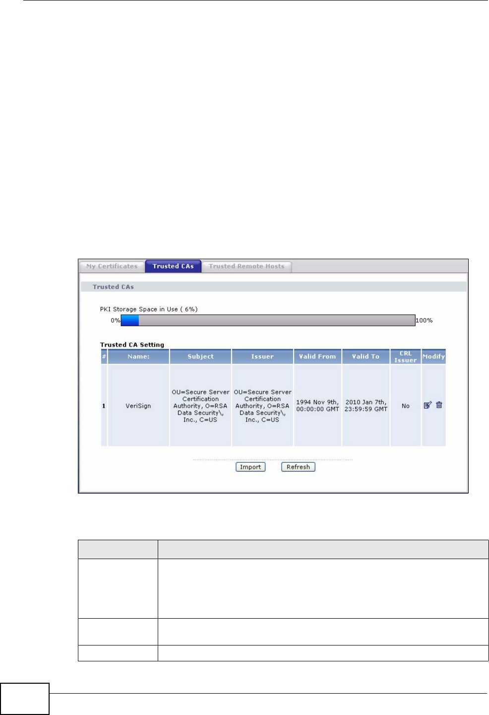
Chapter 15 Certificates
P-2612HWU-F1 User’s Guide
300
screen. Click Return and check your information in the My Certificate Create
screen. Make sure that the certification authority information is correct and that
your Internet connection is working properly if you want the ZyXEL Device to
enroll a certificate online.
15.5 Trusted CAs
Click Security > Certificates > Trusted CAs to open the Trusted CAs screen.
This screen displays a summary list of certificates of the certification authorities
that you have set the ZyXEL Device to accept as trusted. The ZyXEL Device
accepts any valid certificate signed by a certification authority on this list as being
trustworthy; thus you do not need to import any certificate that is signed by one
of these certification authorities.
Figure 178 Security > Certificates > Trusted CAs
The following table describes the labels in this screen.
Table 96 Security > Certificates > Trusted CAs
LABEL DESCRIPTION
PKI Storage
Space in Use This bar displays the percentage of the ZyXEL Device’s PKI storage
space that is currently in use. The bar turns from blue to red when the
maximum is being approached. When the bar is red, you should
consider deleting expired or unnecessary certificates before adding
more certificates.
# This field displays the certificate index number. The certificates are
listed in alphabetical order.
Name This field displays the name used to identify this certificate.