ZyXEL Communications P2612HWUFX Dual WAN ADSL2+ VoIP IAD User Manual SMG 700 User s Guide V1 00 Nov 2004
ZyXEL Communications Corporation Dual WAN ADSL2+ VoIP IAD SMG 700 User s Guide V1 00 Nov 2004
Contents
- 1. manual part 3
- 2. Usermanual part 1
- 3. Usermanual part 2
- 4. Usermanual part 4
Usermanual part 1

www.zyxel.com
www.zyxel.com
P-2612HWU-F1
802.11g Wireless ADSL VoIP IAD
Copyright © 2009
ZyXEL Communications Corporation
Firmware Version 3.70
Edition 1, 8/2009
Default Login Details
IP Address http://192.168.1.1
User Name: adminpldt
Password: 1234567890
About This User's Guide
P-2612HWU-F1 User’s Guide 3
About This User's Guide
Intended Audience
This manual is intended for people who want to configure the ZyXEL Device using
the web configurator.
Related Documentation
•Quick Start Guide
The Quick Start Guide is designed to help you get up and running right away. It
contains information on setting up your network and configuring for Internet
access.
• Support Disc
Refer to the included CD for support documents.
Documentation Feedback
Send your comments, questions or suggestions to: techwriters@zyxel.com.tw
Thank you!
The Technical Writing Team, ZyXEL Communications Corp.,
6 Innovation Road II, Science-Based Industrial Park, Hsinchu, 30099, Taiwan.
Need More Help?
More help is available at www.zyxel.com.

About This User's Guide
P-2612HWU-F1 User’s Guide
4
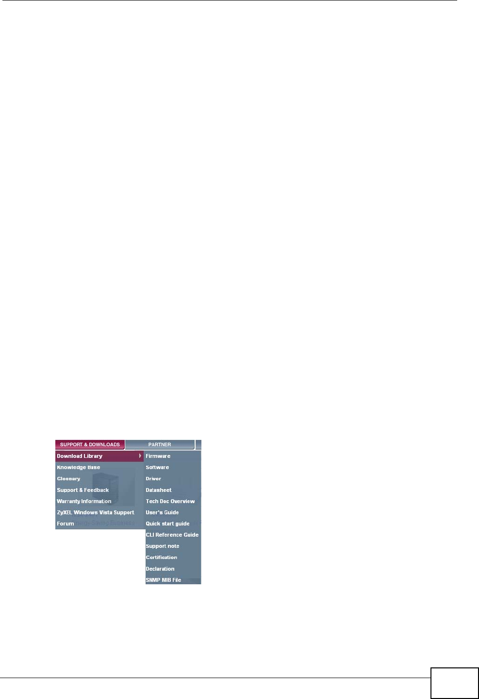
• Download Library
Search for the latest product updates and documentation from this link. Read
the Tech Doc Overview to find out how to efficiently use the User Guide, Quick
Start Guide and Command Line Interface Reference Guide in order to better
understand how to use your product.
• Knowledge Base
If you have a specific question about your product, the answer may be here.
This is a collection of answers to previously asked questions about ZyXEL
products.
•Forum
This contains discussions on ZyXEL products. Learn from others who use ZyXEL
products and share your experiences as well.
Customer Support
Should problems arise that cannot be solved by the methods listed above, you
should contact your vendor. If you cannot contact your vendor, then contact a
ZyXEL office for the region in which you bought the device.
See http://www.zyxel.com/web/contact_us.php for contact information. Please
have the following information ready when you contact an office.
• Product model and serial number.
•Warranty Information.
• Date that you received your device.
• Brief description of the problem and the steps you took to solve it.

Document Conventions
P-2612HWU-F1 User’s Guide 5
Document Conventions
Warnings and Notes
These are how warnings and notes are shown in this User’s Guide.
Warnings tell you about things that could harm you or your device.
Note: Notes tell you other important information (for example, other things you may
need to configure or helpful tips) or recommendations.
Syntax Conventions
• The P-2612HW Series may be referred to as the “ZyXEL Device”, the “device”,
the “system” or the “product” in this User’s Guide.
• Product labels, screen names, field labels and field choices are all in bold font.
• A key stroke is denoted by square brackets and uppercase text, for example,
[ENTER] means the “enter” or “return” key on your keyboard.
• “Enter” means for you to type one or more characters and then press the
[ENTER] key. “Select” or “choose” means for you to use one of the predefined
choices.
• A right angle bracket ( > ) within a screen name denotes a mouse click. For
example, Maintenance > Log > Log Setting means you first click
Maintenance in the navigation panel, then the Log sub menu and finally the
Log Setting tab to get to that screen.
• Units of measurement may denote the “metric” value or the “scientific” value.
For example, “k” for kilo may denote “1000” or “1024”, “M” for mega may
denote “1000000” or “1048576” and so on.
• “e.g.,” is a shorthand for “for instance”, and “i.e.,” means “that is” or “in other
words”.
Document Conventions
P-2612HWU-F1 User’s Guide
6
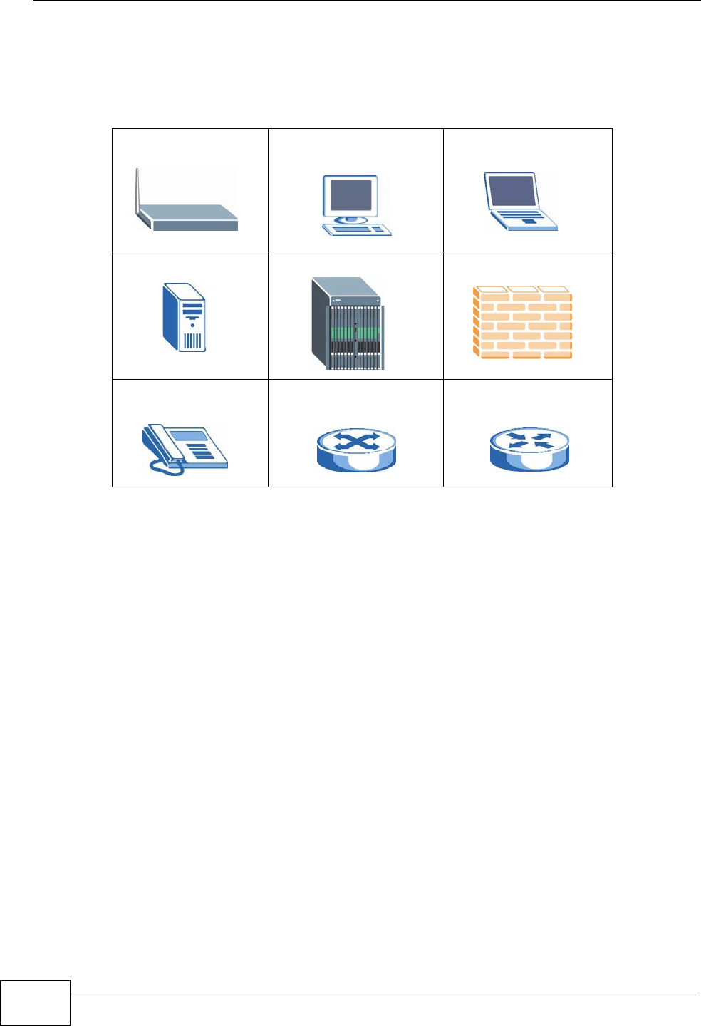
Icons Used in Figures
Figures in this User’s Guide may use the following generic icons. The ZyXEL Device
icon is not an exact representation of your device.
ZyXEL Device Computer Notebook computer
Server DSLAM Firewall
Telephone Switch Router

Safety Warnings
P-2612HWU-F1 User’s Guide 7
Safety Warnings
• Do NOT use this product near water, for example, in a wet basement or near a swimming
pool.
• Do NOT expose your device to dampness, dust or corrosive liquids.
• Do NOT store things on the device.
• Do NOT install, use, or service this device during a thunderstorm. There is a remote risk
of electric shock from lightning.
• Connect ONLY suitable accessories to the device.
• Do NOT open the device or unit. Opening or removing covers can expose you to
dangerous high voltage points or other risks. ONLY qualified service personnel should
service or disassemble this device. Please contact your vendor for further information.
• Make sure to connect the cables to the correct ports.
• Place connecting cables carefully so that no one will step on them or stumble over them.
• Always disconnect all cables from this device before servicing or disassembling.
• Use ONLY an appropriate power adaptor or cord for your device.
• Connect the power adaptor or cord to the right supply voltage (for example, 110V AC in
North America or 230V AC in Europe).
• Do NOT allow anything to rest on the power adaptor or cord and do NOT place the
product where anyone can walk on the power adaptor or cord.
• Do NOT use the device if the power adaptor or cord is damaged as it might cause
electrocution.
• If the power adaptor or cord is damaged, remove it from the device and the power
source.
• Do NOT attempt to repair the power adaptor or cord. Contact your local vendor to order a
new one.
• Do not use the device outside, and make sure all the connections are indoors. There is a
remote risk of electric shock from lightning.
• Do NOT obstruct the device ventilation slots, as insufficient airflow may harm your
device.
• Use only No. 26 AWG (American Wire Gauge) or larger telecommunication line cord.
• Antenna Warning! This device meets ETSI and FCC certification requirements when using
the included antenna(s). Only use the included antenna(s).
Your product is marked with this symbol, which is known as the WEEE mark. WEEE
stands for Waste Electronics and Electrical Equipment. It means that used electrical
and electronic products should not be mixed with general waste. Used electrical and
electronic equipment should be treated separately.

Safety Warnings
P-2612HWU-F1 User’s Guide
8

Contents Overview
P-2612HWU-F1 User’s Guide 9
Contents Overview
Introduction ............................................................................................................................23
Introducing the ZyXEL Device ...................................................................................................25
Introducing the Web Configurator .............................................................................................. 33
Wizards...................................................................................................................................... 41
Tutorial ....................................................................................................................................... 59
Advanced ................................................................................................................................89
Status Screens .......................................................................................................................... 91
WAN Setup .............................................................................................................................. 101
LAN Setup ................................................................................................................................117
Wireless LAN ........................................................................................................................... 133
Network Address Translation (NAT) ........................................................................................ 165
Voice ........................................................................................................................................ 181
Phone Usage ........................................................................................................................... 217
Firewall .................................................................................................................................... 225
Content Filtering ...................................................................................................................... 247
VPN ......................................................................................................................................... 253
Certificates ............................................................................................................................... 287
Static Route ............................................................................................................................. 313
802.1Q/1P ............................................................................................................................... 317
Quality of Service (QoS) .......................................................................................................... 329
Dynamic DNS Setup ................................................................................................................ 345
Remote Management Configuration ........................................................................................ 349
Universal Plug-and-Play (UPnP) ............................................................................................. 361
File Sharing ............................................................................................................................. 375
Sharing a USB Printer ............................................................................................................. 389
Maintenance, Troubleshooting and Specifications ..........................................................409
System ......................................................................................................................................411
Logs ........................................................................................................................................ 417
Call History ............................................................................................................................. 433
Tools ........................................................................................................................................ 439
Diagnostic ............................................................................................................................... 459
Troubleshooting ....................................................................................................................... 461
Product Specifications ............................................................................................................. 471
Appendices and Index .........................................................................................................483

Contents Overview
P-2612HWU-F1 User’s Guide
10

Table of Contents
P-2612HWU-F1 User’s Guide 11
Table of Contents
About This User's Guide..........................................................................................................3
Document Conventions............................................................................................................5
Safety Warnings........................................................................................................................7
Contents Overview ...................................................................................................................9
Table of Contents....................................................................................................................11
Part I: Introduction................................................................................. 23
Chapter 1
Introducing the ZyXEL Device...............................................................................................25
1.1 Overview .............................................................................................................................. 25
1.1.1 Internet Access ..........................................................................................................25
1.1.2 VoIP Features ............................................................................................................27
1.1.3 ZyXEL Device’s USB Support .................................................................................... 27
1.2 Ways to Manage the ZyXEL Device .................................................................................... 28
1.3 Good Habits for Managing the ZyXEL Device ..................................................................... 28
1.4 LEDs (Lights) ....................................................................................................................... 28
1.5 The RESET Button .............................................................................................................. 30
1.6 The WLAN Button ................................................................................................................ 30
Chapter 2
Introducing the Web Configurator ........................................................................................33
2.1 Web Configurator Overview ................................................................................................. 33
2.1.1 Accessing the Web Configurator ................................................................................ 33
2.2 Web Configurator Main Screen ........................................................................................... 34
2.2.1 Title Bar ...................................................................................................................... 35
2.2.2 Navigation Panel ........................................................................................................ 35
2.2.3 Main Window ..............................................................................................................39
2.2.4 Status Bar ................................................................................................................... 39
Chapter 3
Wizards ....................................................................................................................................41
3.1 Overview .............................................................................................................................. 41
3.2 Internet Access Wizard Setup ............................................................................................. 41

Table of Contents
P-2612HWU-F1 User’s Guide
12
3.2.1 Manual Configuration ................................................................................................. 44
3.3 Wireless Connection Wizard Setup ..................................................................................... 49
3.3.1 Manually Assign a WPA-PSK key .............................................................................. 52
3.3.2 Manually Assign a WEP Key ...................................................................................... 53
3.4 VoIP Setup Wizard .............................................................................................................. 54
3.4.1 SIP Settings ............................................................................................................... 55
3.4.2 Registration Complete ................................................................................................ 56
Chapter 4
Tutorial.....................................................................................................................................59
4.1 Overview .............................................................................................................................. 59
4.2 How to Set up a Wireless Network ...................................................................................... 59
4.2.1 Example Parameters .................................................................................................. 59
4.2.2 Configuring the AP ..................................................................................................... 60
4.2.3 Configuring the Wireless Client .................................................................................. 62
4.3 Using NAT with Multiple Public IP Addresses ...................................................................... 68
4.3.1 Example Parameters and Scenario ........................................................................... 68
4.3.2 Configuring the WAN Connection with a Static IP Address ........................................ 69
4.3.3 Public IP Address Mapping ........................................................................................ 72
4.3.4 Forwarding Traffic from the WAN to a Local Computer .............................................. 76
4.3.5 Allow WAN-to-LAN Traffic through the Firewall .......................................................... 77
4.3.6 Testing the Connections ............................................................................................. 85
4.4 Using NAT with Multiple Game Players ............................................................................... 85
4.5 How to Make a VoIP Call ..................................................................................................... 86
4.5.1 VoIP Calls With a Registered SIP Account ................................................................ 86
Part II: Advanced.................................................................................... 89
Chapter 5
Status Screens........................................................................................................................91
5.1 Status Screen ...................................................................................................................... 91
5.2 Any IP Table ........................................................................................................................ 96
5.3 WLAN Status ....................................................................................................................... 96
5.4 Packet Statistics .................................................................................................................. 97
5.5 VoIP Statistics ...................................................................................................................... 99
Chapter 6
WAN Setup.............................................................................................................................101
6.1 Overview ............................................................................................................................ 101
6.1.1 What You Can Do in the WAN Screens ................................................................... 101
6.1.2 What You Need to Know About WAN ...................................................................... 101

Table of Contents
P-2612HWU-F1 User’s Guide 13
6.1.3 Before You Begin ..................................................................................................... 102
6.2 The Internet Access Setup Screen ................................................................................... 103
6.2.1 Advanced Internet Access Setup ............................................................................. 106
6.3 The WAN Backup Setup Screen ...................................................................................... 108
6.4 WAN Technical Reference ................................................................................................. 109
6.4.1 Encapsulation ........................................................................................................... 109
6.4.2 Multiplexing ............................................................................................................... 111
6.4.3 VPI and VCI .............................................................................................................. 111
6.4.4 IP Address Assignment .............................................................................................111
6.4.5 Nailed-Up Connection (PPP) ....................................................................................112
6.4.6 NAT ...........................................................................................................................112
6.4.7 Metric .......................................................................................................................112
6.4.8 Traffic Shaping ..........................................................................................................113
6.5 Traffic Redirect ...................................................................................................................115
Chapter 7
LAN Setup.............................................................................................................................. 117
7.1 Overview .............................................................................................................................117
7.1.1 What You Can Do in the LAN Screens ......................................................................117
7.1.2 What You Need To Know About LAN ........................................................................118
7.1.3 Before You Begin ......................................................................................................118
7.2 The LAN IP Screen .............................................................................................................118
7.2.1 The Advanced LAN Setup Screen ........................................................................... 120
7.2.2 Configuring the Advanced LAN Setup Screen ......................................................... 121
7.3 The LAN Client List Screen ............................................................................................... 122
7.4 The LAN IP Alias Screen ................................................................................................... 124
7.5 LAN Technical Reference .................................................................................................. 125
7.5.1 LANs, WANs and the ZyXEL Device ........................................................................ 126
7.5.2 DHCP Setup ............................................................................................................. 126
7.5.3 DNS Server Addresses ............................................................................................ 126
7.5.4 TCP/IP ...................................................................................................................... 127
7.5.5 RIP Setup ................................................................................................................. 128
7.5.6 Multicast ................................................................................................................... 129
7.5.7 Any IP ....................................................................................................................... 129
Chapter 8
Wireless LAN.........................................................................................................................133
8.1 Overview ............................................................................................................................ 133
8.1.1 What You Can Do in the Wireless LAN Screens ...................................................... 133
8.1.2 What You Need to Know About Wireless ................................................................. 134
8.1.3 Before You Start ....................................................................................................... 136
8.2 AP Screen ........................................................................................................................ 136
8.2.1 No Security ............................................................................................................... 138

Table of Contents
P-2612HWU-F1 User’s Guide
14
8.2.2 WEP Encryption ....................................................................................................... 139
8.2.3 WPA(2)-PSK ............................................................................................................ 140
8.2.4 WPA(2) Authentication Screen ................................................................................. 142
8.2.5 Wireless LAN Advanced Setup ............................................................................... 144
8.3 More AP Screen ................................................................................................................ 145
8.3.1 More AP Edit ............................................................................................................ 146
8.4 MAC Filter ..................................................................................................................... 147
8.5 WPS .................................................................................................................................. 148
8.6 WPS Station ...................................................................................................................... 149
8.7 WDS Screen ..................................................................................................................... 150
8.8 Scheduling Screen ........................................................................................................... 152
8.9 Wireless LAN Technical Reference ................................................................................... 153
8.9.1 Additional Wireless Terms ........................................................................................ 153
8.9.2 Wireless Security Overview ..................................................................................... 153
8.9.3 MBSSID ...................................................................................................................156
8.9.4 Wireless Distribution System (WDS) ........................................................................ 156
8.9.5 WiFi Protected Setup ............................................................................................... 157
Chapter 9
Network Address Translation (NAT)....................................................................................165
9.1 Overview ........................................................................................................................... 165
9.1.1 What You Can Do in the NAT Screens ..................................................................... 165
9.1.2 What You Need To Know About NAT ....................................................................... 165
9.2 NAT General Setup ............................................................................................................ 166
9.3 Port Forwarding ............................................................................................................... 168
9.3.1 Configuring the Port Forwarding Screen .................................................................. 169
9.3.2 Port Forwarding Rule Edit ....................................................................................... 171
9.4 Address Mapping .............................................................................................................. 172
9.4.1 Address Mapping Rule Edit ..................................................................................... 173
9.4.2 SIP ALG .................................................................................................................. 174
9.5 NAT Technical Reference .................................................................................................. 175
9.5.1 NAT Definitions ........................................................................................................ 175
9.5.2 What NAT Does ....................................................................................................... 176
9.5.3 How NAT Works ....................................................................................................... 176
9.5.4 NAT Application ........................................................................................................ 178
9.5.5 NAT Mapping Types ................................................................................................. 178
Chapter 10
Voice.......................................................................................................................................181
10.1 Overview .......................................................................................................................... 181
10.1.1 What You Can Do in the VoIP Screens .................................................................. 181
10.1.2 What You Need to Know About VoIP ..................................................................... 182
10.1.3 Before You Begin ................................................................................................... 183

Table of Contents
P-2612HWU-F1 User’s Guide 15
10.2 The SIP Settings Screen ................................................................................................ 183
10.3 The Advanced SIP Setup Screen ................................................................................... 186
10.4 The SIP QoS Screen ...................................................................................................... 189
10.5 The Analog Phone Screen ............................................................................................. 190
10.6 The Advanced Analog Phone Setup Screen .................................................................. 190
10.6.1 Configuring the Advanced Analog Phone Screen .................................................. 191
10.7 The Phone Settings Ext. Table Screen ........................................................................... 193
10.8 The Common Phone Settings Screen ............................................................................ 194
10.9 The Phone Region Screen ............................................................................................. 195
10.10 The Speed Dial Screen .................................................................................................. 196
10.11 Incoming Call Policy Screen ......................................................................................... 199
10.12 SIP Prefix Screen .......................................................................................................... 201
10.13 SIP Technical Reference ............................................................................................... 202
10.13.1 VoIP ...................................................................................................................... 202
10.13.2 SIP ...................................................................................................................... 202
10.13.3 Quality of Service (QoS) .......................................................................................211
10.13.4 Phone Services Overview .................................................................................... 212
Chapter 11
Phone Usage.........................................................................................................................217
11.1 Overview .......................................................................................................................... 217
11.2 Dialing a Telephone Number ............................................................................................ 217
11.3 Using Speed Dial to Dial a Telephone Number ................................................................ 217
11.4 Using Call Park and Pickup ............................................................................................. 217
11.5 Checking the ZyXEL Device’s IP Address ....................................................................... 218
11.6 Auto Provisioning and Auto Firmware Upgrade ............................................................... 218
11.7 Phone Services Overview ................................................................................................ 219
11.7.1 The Flash Key ........................................................................................................ 219
11.7.2 Europe Type Supplementary Phone Services ........................................................ 219
11.7.3 USA Type Supplementary Services ....................................................................... 221
11.8 Phone Functions Summary .............................................................................................. 223
Chapter 12
Firewall...................................................................................................................................225
12.1 Overview .......................................................................................................................... 225
12.1.1 What You Can Do in the Firewall Screens ............................................................. 225
12.1.2 What You Need to Know About Firewall ................................................................ 226
12.1.3 Firewall Rule Setup Example ................................................................................. 226
12.2 The Firewall General Screen ........................................................................................... 230
12.3 The Firewall Rule Screen ................................................................................................ 232
12.3.1 Configuring Firewall Rules .................................................................................... 233
12.3.2 Customized Services ............................................................................................ 236
12.3.3 Configuring a Customized Service ....................................................................... 237

Table of Contents
P-2612HWU-F1 User’s Guide
16
12.4 The Firewall Threshold Screen ........................................................................................ 237
12.4.1 Threshold Values ................................................................................................... 238
12.4.2 Configuring Firewall Thresholds ............................................................................. 239
12.5 Firewall Technical Reference ........................................................................................... 241
12.5.1 Firewall Rules Overview ......................................................................................... 241
12.5.2 Guidelines For Enhancing Security With Your Firewall .......................................... 242
12.5.3 Security Considerations ......................................................................................... 243
12.5.4 Triangle Route ........................................................................................................ 243
Chapter 13
Content Filtering ...................................................................................................................247
13.1 Overview ......................................................................................................................... 247
13.1.1 What You Can Do in the Content Filter Screens .................................................... 247
13.1.2 What You Need to Know About Content Filtering .................................................. 247
13.1.3 Before You Begin ................................................................................................... 247
13.1.4 Content Filtering Example ...................................................................................... 248
13.2 The Keyword Screen ...................................................................................................... 250
13.3 The Schedule Screen ..................................................................................................... 251
13.4 The Trusted Screen ........................................................................................................ 252
Chapter 14
VPN.........................................................................................................................................253
14.1 Overview .......................................................................................................................... 253
14.1.1 What You Can Do in the VPN Screens .................................................................. 253
14.1.2 What You Need to Know About IPSec VPN ........................................................... 254
14.1.3 Before You Begin ................................................................................................... 255
14.2 VPN Setup Screen .........................................................................................................256
14.3 The VPN Edit Screen ..................................................................................................... 258
14.4 Configuring Advanced IKE Settings ............................................................................... 264
14.5 Manual Key Setup ........................................................................................................... 267
14.5.1 Security Parameter Index (SPI) ............................................................................ 267
14.6 Configuring Manual Key ................................................................................................. 268
14.7 Viewing SA Monitor ........................................................................................................ 271
14.8 Configuring VPN Global Setting ..................................................................................... 273
14.9 IPSec VPN Technical Reference ..................................................................................... 273
14.9.1 IPSec Architecture ................................................................................................. 274
14.9.2 IPSec and NAT ....................................................................................................... 274
14.9.3 VPN, NAT, and NAT Traversal ............................................................................... 275
14.9.4 Encapsulation ......................................................................................................... 277
14.9.5 IKE Phases ........................................................................................................... 278
14.9.6 Negotiation Mode ................................................................................................... 279
14.9.7 Keep Alive ..............................................................................................................279
14.9.8 Remote DNS Server .............................................................................................. 279

Table of Contents
P-2612HWU-F1 User’s Guide 17
14.9.9 ID Type and Content .............................................................................................. 280
14.9.10 Pre-Shared Key .................................................................................................... 282
14.9.11 Diffie-Hellman (DH) Key Groups .......................................................................... 282
14.9.12 Telecommuter VPN/IPSec Examples ................................................................... 282
Chapter 15
Certificates ............................................................................................................................287
15.1 Overview .......................................................................................................................... 287
15.1.1 What You Can Do in the Certificate Screens ......................................................... 287
15.1.2 What You Need to Know About Certificates ........................................................... 287
15.1.3 Verifying a Certificate ............................................................................................. 289
15.2 My Certificates ................................................................................................................. 291
15.3 My Certificate Details ...................................................................................................... 293
15.3.1 Using the My Certificate Import Screen ................................................................. 297
15.4 My Certificate Create ...................................................................................................... 298
15.5 Trusted CAs ................................................................................................................... 300
15.6 Trusted CA Import ......................................................................................................... 301
15.7 Trusted CA Details ........................................................................................................... 302
15.8 Trusted Remote Hosts ................................................................................................... 306
15.9 Trusted Remote Host Certificate Details ....................................................................... 307
15.10 Trusted Remote Hosts Import ...................................................................................... 310
Chapter 16
Static Route...........................................................................................................................313
16.1 Overview ....................................................................................................................... 313
16.1.1 What You Can Do in the Static Route Screens ...................................................... 313
16.2 Configuring Static Route ..................................................................................................314
16.2.1 Static Route Edit ................................................................................................... 315
Chapter 17
802.1Q/1P...............................................................................................................................317
17.1 Overview .......................................................................................................................... 317
17.1.1 What You Can Do in the 802.1Q/1P Screens ........................................................ 317
17.1.2 What You Need to Know About 802.1Q/1P ........................................................... 317
17.1.3 802.1Q/1P Example ............................................................................................... 319
17.2 The 802.1Q/1P Group Setting Screen ............................................................................. 324
17.2.1 Editing 802.1Q/1P Group Setting ........................................................................... 325
17.3 The 802.1Q/1P Port Setting Screen ................................................................................ 327
Chapter 18
Quality of Service (QoS).......................................................................................................329
18.1 Overview .......................................................................................................................... 329
18.1.1 What You Can Do in the QoS Screens .................................................................. 329

Table of Contents
P-2612HWU-F1 User’s Guide
18
18.1.2 What You Need to Know About QoS ..................................................................... 330
18.1.3 QoS Class Setup Example ..................................................................................... 330
18.2 The QoS General Screen ............................................................................................... 333
18.3 The Class Setup Screen ................................................................................................ 335
18.3.1 The Class Configuration Screen ........................................................................... 337
18.4 The QoS Monitor Screen ................................................................................................ 341
18.5 QoS Technical Reference ................................................................................................ 341
18.5.1 IEEE 802.1Q Tag ................................................................................................... 342
18.5.2 IP Precedence ........................................................................................................ 342
18.5.3 DiffServ ................................................................................................................. 342
18.5.4 Automatic Priority Queue Assignment ................................................................... 343
Chapter 19
Dynamic DNS Setup .............................................................................................................345
19.1 Overview ......................................................................................................................... 345
19.1.1 What You Can Do in the DDNS Screen ................................................................. 345
19.1.2 What You Need To Know About DDNS .................................................................. 345
19.2 Configuring Dynamic DNS .............................................................................................. 346
Chapter 20
Remote Management Configuration ...................................................................................349
20.1 Overview ......................................................................................................................... 349
20.1.1 What You Can Do in the Remote Management Screens ....................................... 350
20.1.2 What You Need to Know About Remote Management .......................................... 350
20.2 The WWW Screen ........................................................................................................... 351
20.3 The Telnet Screen ........................................................................................................... 352
20.4 The FTP Screen ............................................................................................................. 353
20.5 The SNMP Screen ...........................................................................................................354
20.5.1 Configuring SNMP ................................................................................................. 356
20.6 The DNS Screen ............................................................................................................ 357
20.7 The ICMP Screen ............................................................................................................ 358
Chapter 21
Universal Plug-and-Play (UPnP)..........................................................................................361
21.1 Overview ......................................................................................................................... 361
21.1.1 What You Can Do in the UPnP Screen .................................................................. 361
21.1.2 What You Need to Know About UPnP ................................................................... 361
21.2 The UPnP Screen ............................................................................................................ 363
21.3 Installing UPnP in Windows Example .............................................................................. 363
21.4 Using UPnP in Windows XP Example ............................................................................. 367
Chapter 22
File Sharing ...........................................................................................................................375

Table of Contents
P-2612HWU-F1 User’s Guide 19
22.1 Overview .......................................................................................................................... 375
22.1.1 What You Can Do in the File-Sharing Screens ...................................................... 375
22.1.2 What You Need to Know About File-Sharing ......................................................... 376
22.1.3 Before You Begin ................................................................................................... 376
22.1.4 File-Sharing Examples ........................................................................................... 377
22.2 The Server Settings Screen ........................................................................................... 381
22.3 The User Name and Password Screen ........................................................................... 383
22.3.1 Add or Edit a User Account .................................................................................... 384
22.4 The Share Configuration Screen ..................................................................................... 384
22.4.1 Default Share Directory List ................................................................................... 385
22.4.2 User-Defined Share Directory List ......................................................................... 385
22.4.3 Add or Edit a User-Defined Share .......................................................................... 386
22.4.4 Browse ................................................................................................................... 387
Chapter 23
Sharing a USB Printer ..........................................................................................................389
23.1 Overview .......................................................................................................................... 389
23.1.1 What You Need to Know About Printer Sharing ..................................................... 389
23.1.2 Before You Begin ................................................................................................... 390
23.1.3 What You Can Do with Printer Sharing .................................................................. 390
23.2 ZyXEL Device Print Server Compatible USB Printers ..................................................... 406
Part III: Maintenance, Troubleshooting and Specifications ............. 409
Chapter 24
System ................................................................................................................................... 411
24.1 Overview ...........................................................................................................................411
24.1.1 What You Can Do in the System Settings Screens .................................................411
24.1.2 What You Need to Know About System Settings ....................................................411
24.2 The General Screen ........................................................................................................412
24.3 The Time Setting Screen ................................................................................................ 414
Chapter 25
Logs ......................................................................................................................................417
25.1 Overview ......................................................................................................................... 417
25.1.1 What You Can Do in the Log Screens .................................................................... 417
25.1.2 What You Need To Know About Logs .................................................................... 417
25.2 The View Log Screen ...................................................................................................... 417
25.3 The Log Settings Screen ................................................................................................. 418
25.4 SMTP Error Messages .................................................................................................... 421
25.4.1 Example E-mail Log ............................................................................................... 421

Table of Contents
P-2612HWU-F1 User’s Guide
20
25.5 Log Descriptions .............................................................................................................. 422
Chapter 26
Call History ...........................................................................................................................433
26.1 Overview .......................................................................................................................... 433
26.1.1 What You Can Do in the Call History Screens ....................................................... 433
26.2 Call History Summary Screen ........................................................................................ 433
26.3 Viewing the Call History .................................................................................................. 434
26.4 Configuring Call History Settings .................................................................................... 435
Chapter 27
Tools.......................................................................................................................................439
27.1 Overview .......................................................................................................................... 439
27.1.1 What You Can Do in the Tool Screens ................................................................... 439
27.1.2 What You Need To Know About Tools .................................................................... 439
27.1.3 Before You Begin ................................................................................................... 441
27.1.4 Tool Examples ........................................................................................................ 441
27.2 Firmware Upgrade Screen ............................................................................................ 446
27.3 The Configuration Screen ................................................................................................ 449
27.3.1 Reset to Factory Defaults ...................................................................................... 451
27.4 Restart ............................................................................................................................. 452
27.5 Using FTP or TFTP to Back Up Configuration ................................................................ 452
27.5.1 Using the FTP Commands to Back Up Configuration ............................................ 452
27.5.2 FTP Command Configuration Backup Example ................................................... 453
27.5.3 Configuration Backup Using GUI-based FTP Clients ............................................ 453
27.5.4 Backup Configuration Using TFTP ......................................................................... 453
27.5.5 TFTP Command Configuration Backup Example .................................................. 454
27.5.6 Configuration Backup Using GUI-based TFTP Clients .......................................... 455
27.6 Using FTP or TFTP to Restore Configuration ............................................................... 455
27.6.1 Restore Using FTP Session Example .................................................................... 456
27.7 FTP and TFTP Firmware and Configuration File Uploads .............................................. 456
27.7.1 FTP File Upload Command from the DOS Prompt Example ................................. 456
27.7.2 FTP Session Example of Firmware File Upload .................................................... 457
27.7.3 TFTP File Upload ................................................................................................... 457
27.7.4 TFTP Upload Command Example ......................................................................... 458
Chapter 28
Diagnostic .............................................................................................................................459
28.1 Overview .......................................................................................................................... 459
28.1.1 What You Can Do in the Diagnostic Screens ......................................................... 459
28.2 The General Diagnostic Screen ...................................................................................... 459
Chapter 29
Troubleshooting....................................................................................................................461

Table of Contents
P-2612HWU-F1 User’s Guide 21
29.1 Overview .......................................................................................................................... 461
29.2 Power, Hardware Connections, and LEDs ...................................................................... 461
29.3 ZyXEL Device Access and Login .................................................................................... 462
29.4 Internet Access ................................................................................................................ 464
29.5 Phone Calls and VoIP ......................................................................................................465
29.6 Multiple SIP Accounts ...................................................................................................... 466
29.6.1 Outgoing Calls ........................................................................................................ 467
29.6.2 Incoming Calls ........................................................................................................ 468
29.7 USB Device Connection .................................................................................................. 469
Chapter 30
Product Specifications.........................................................................................................471
Part IV: Appendices and Index ........................................................... 483
Appendix A Setting Up Your Computer’s IP Address...........................................................485
Appendix B Pop-up Windows, JavaScripts and Java Permissions...................................... 511
Appendix C IP Addresses and Subnetting ...........................................................................521
Appendix D Wireless LANs ..................................................................................................533
Appendix E Common Services.............................................................................................557
Appendix F Legal Information ..............................................................................................561
Index.......................................................................................................................................565

Table of Contents
P-2612HWU-F1 User’s Guide
22

23
PART I
Introduction
Introducing the ZyXEL Device (25)
Introducing the Web Configurator (33)
Wizards (41)
Tutorial (59)

24

P-2612HWU-F1 User’s Guide 25
CHAPTER 1
Introducing the ZyXEL Device
1.1 Overview
The ZyXEL Device is an Integrated Access Device (IAD) that combines an ADSL2+
router with Voice over IP (VoIP) communication capabilities to allow you to use a
traditional analog telephone to make Internet calls. By integrating DSL and NAT,
you are provided with ease of installation and high-speed, shared Internet access.
The ZyXEL Device is also a complete security solution with a robust firewall and
content filtering.
Please refer to the following description of the product name format.
• “H” denotes an integrated 4-port hub (switch).
• “W” denotes wireless functionality. There is an embedded mini-PCI module for
IEEE 802.11g wireless LAN connectivity. All wireless features documented in this
user’s guide refer to the “W” models only.
• “U” denotes a USB port used to share files via a USB memory stick or a USB
hard drive. The ZyXEL Device can also function as a print server with an USB
printer connected.
See the chapter on product specifications for a full list of features.
1.1.1 Internet Access
Your ZyXEL Device provides shared Internet access by connecting the DSL port to
the DSL or MODEM jack on a splitter or your telephone jack. If you prefer not to
use a DSL line and you have another broadband modem or router (such as ADSL)
available, you can push the DSL/WAN switch (on the rear panel) to the WAN
side and connect the WAN port to the broadband modem or router. This way, you
can access the Internet via an Ethernet connection and still use the QoS, Firewall
and VoIP functions on the ZyXEL Device.
Chapter 1 Introducing the ZyXEL Device
P-2612HWU-F1 User’s Guide
26
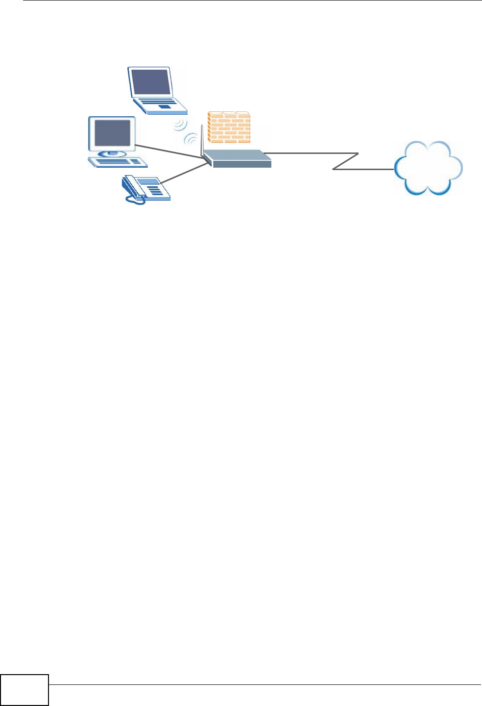
Computers can connect to the ZyXEL Device’s LAN ports (or wirelessly).
Figure 1 ZyXEL Device’s Router Features
You can also configure firewall and content filtering on the ZyXEL Device for
secure Internet access. When the firewall is on, all incoming traffic from the
Internet to your network is blocked unless it is initiated from your network. This
means that probes from the outside to your network are not allowed, but you can
safely browse the Internet and download files.
Use content filtering to block access to specific web sites, with URLs containing
keywords that you specify. You can define time periods and days during which
content filtering is enabled and include or exclude particular computers on your
network from content filtering. For example, you could block access to certain web
sites for the kids.
Use QoS to efficiently manage traffic on your network by giving priority to certain
types of traffic and/or to particular computers. For example, you could make sure
that the ZyXEL Device gives voice over Internet calls high priority, and/or limit
bandwidth devoted to the boss’s excessive file downloading.
Internet
LAN
Chapter 1 Introducing the ZyXEL Device
P-2612HWU-F1 User’s Guide 27
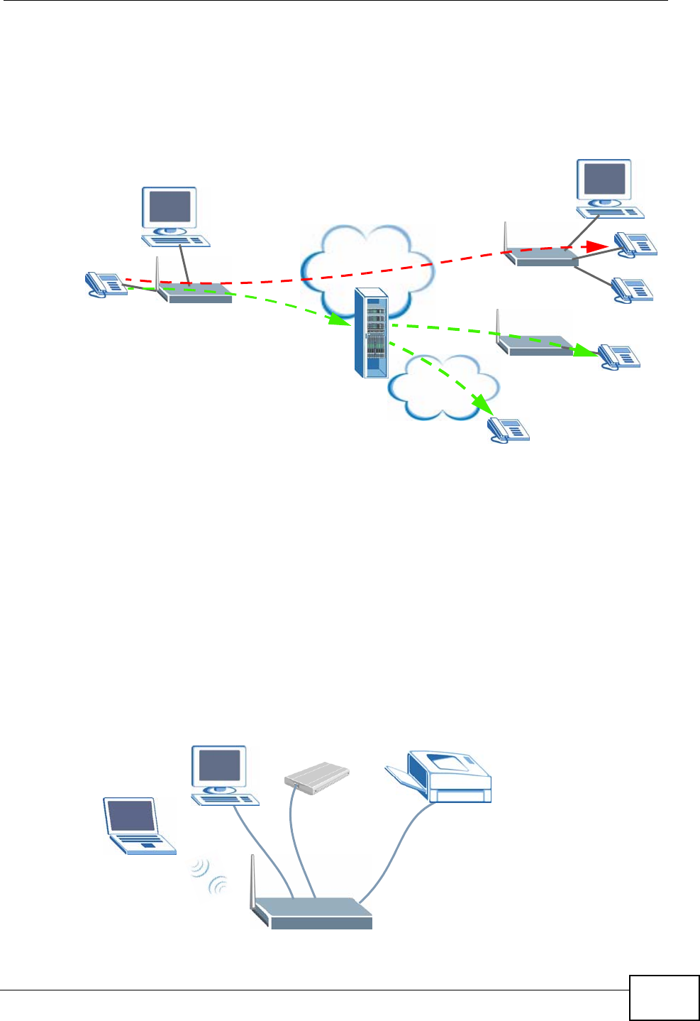
1.1.2 VoIP Features
You can register up to 2 SIP (Session Initiation Protocol) accounts and use the
ZyXEL Device to make and receive VoIP telephone calls:
Figure 2 ZyXEL Device’s VoIP Features
• Peer-to-Peer calls (A) - Use the ZyXEL Device to make a call to the recipient’s IP
address without using a SIP proxy server.
• Calls via a VoIP service provider (B) - The ZyXEL Device sends your call to a
VoIP service provider’s SIP server which forwards your calls to either VoIP or
PSTN phones.
1.1.3 ZyXEL Device’s USB Support
Use the built-in USB 2.0 port to share files via a USB memory stick or a USB hard
drive (A). Alternatively, you can add a USB printer (B) and make it available on
your local area network.
Figure 3 File Sharing Overview
Internet
PSTN
A
B
AB

Chapter 1 Introducing the ZyXEL Device
P-2612HWU-F1 User’s Guide
28
1.2 Ways to Manage the ZyXEL Device
Use any of the following methods to manage the ZyXEL Device.
• Web Configurator. This is recommended for everyday management of the ZyXEL
Device using a (supported) web browser.
• Command Line Interface. Line commands are mostly used for troubleshooting
by service engineers.
• FTP for firmware upgrades and configuration backup/restore.
• SNMP. The device can be monitored by an SNMP manager. See the SNMP
chapter in this User’s Guide.
• SPTGEN. SPTGEN is a text configuration file that allows you to configure the
device by uploading an SPTGEN file. This is especially convenient if you need to
configure many devices of the same type.
1.3 Good Habits for Managing the ZyXEL Device
Do the following things regularly to make the ZyXEL Device more secure and to
manage the ZyXEL Device more effectively.
• Change the password. Use a password that’s not easy to guess and that consists
of different types of characters, such as numbers and letters.
• Write down the password and put it in a safe place.
• Back up the configuration (and make sure you know how to restore it).
Restoring an earlier working configuration may be useful if the device becomes
unstable or even crashes. If you forget your password, you will have to reset the
ZyXEL Device to its factory default settings. If you backed up an earlier
configuration file, you would not have to totally re-configure the ZyXEL Device.
You could simply restore your last configuration.
1.4 LEDs (Lights)
The following graphic displays the labels of the LEDs.
Figure 4 LEDs on the Top of the Device

Chapter 1 Introducing the ZyXEL Device
P-2612HWU-F1 User’s Guide 29
None of the LEDs are on if the ZyXEL Device is not receiving power.
Table 1 LED Descriptions
LED COLOR STATUS DESCRIPTION
POWER Green On The ZyXEL Device is receiving power and ready for use.
Blinking The ZyXEL Device is self-testing.
Red On The ZyXEL Device detected an error while self-testing, or
there is a device malfunction.
Off The ZyXEL Device is not receiving power.
ETHERNET
1-4 Green On The ZyXEL Device has an Ethernet connection with a
device on the Local Area Network (LAN).
Blinking The ZyXEL Device is sending/receiving data to /from the
LAN.
Off The ZyXEL Device does not have an Ethernet connection
with the LAN.
WLAN Green On The wireless network is activated and is operating in
IEEE 802.11b/g mode.
Blinking The ZyXEL Device is communicating with other wireless
clients.
Off The wireless network is not activated.
DSL Green On This light applies when the ZyXEL Device is in DSL WAN
mode. The DSL line is up.
Blinking The ZyXEL Device is initializing the DSL line.
Off The DSL line is down.
INTERNET Green On The ZyXEL Device has an IP connection but no traffic.
Your device has a WAN IP address (either static or
assigned by a DHCP server), PPP negotiation was
successfully completed (if used) and the DSL connection
is up.
Blinking The ZyXEL Device is sending or receiving IP traffic.
Red On The ZyXEL Device attempted to make an IP connection
but failed. Possible causes are no response from a DHCP
server, no PPPoE response, PPPoE authentication failed.
Off The ZyXEL Device does not have an IP connection.
WAN Green On This light applies when the ZyXEL Device is in Ethernet
WAN mode. The ZyXEL Device has an Ethernet
connection with a device on the WAN.
Blinking The ZyXEL Device is sending/receiving data to/from the
WAN.
Off The ZyXEL Device does not have an Ethernet connection
with the WAN.

Chapter 1 Introducing the ZyXEL Device
P-2612HWU-F1 User’s Guide
30
Refer to the Quick Start Guide for information on hardware connections.
1.5 The RESET Button
If you forget your password or cannot access the web configurator, you will need
to use the RESET button at the back of the device to reload the factory-default
configuration file. This means that you will lose all configurations that you had
previously and the passwords will be reset to the defaults.
1Make sure the POWER LED is on (not blinking).
2To set the device back to the factory default settings, press the RESET button for
ten seconds or until the POWER LED begins to blink and then release it. When the
POWER LED begins to blink, the defaults have been restored and the device
restarts.
1.6 The WLAN Button
Use the WLAN button ( ) on the top of the device to turn the wireless LAN off
or on. You can also use it to activate WPS in order to quickly set up a wireless
network with strong security. Make sure the POWER LED is on (not blinking)
before using the WLAN button.
•Press the WLAN button for one second and release it. The WLAN LED should
change from on to off or vice versa.
PHONE Green On A SIP account is registered for the phone port.
Blinking A telephone connected to the phone port has its receiver
off of the hook or there is an incoming call.
Orange On A SIP account is registered for the phone port and there
is a voice message in the corresponding SIP account.
Blinking A telephone connected to the phone port has its receiver
off of the hook and there is a voice message in the
corresponding SIP account.
Off The phone port does not have a SIP account registered.
USB Green On The ZyXEL Device recognizes a USB connection.
Blinking The ZyXEL Device is sending/receiving data to /from the
USB device connected to it.
Off The ZyXEL Device does not detect a USB connection.
Table 1 LED Descriptions
LED COLOR STATUS DESCRIPTION

Chapter 1 Introducing the ZyXEL Device
P-2612HWU-F1 User’s Guide 31
• Press the WLAN button for five seconds to turn on WPS. See Section 8.9.5.1 on
page 157 for more on using WPS to configure your wireless clients.

Chapter 1 Introducing the ZyXEL Device
P-2612HWU-F1 User’s Guide
32

P-2612HWU-F1 User’s Guide 33
CHAPTER 2
Introducing the Web
Configurator
2.1 Web Configurator Overview
The web configurator is an HTML-based management interface that allows easy
device setup and management via Internet browser. Use Internet Explorer 6.0 and
later or Netscape Navigator 7.0 and later versions. The recommended screen
resolution is 1024 by 768 pixels.
In order to use the web configurator you need to allow:
• Web browser pop-up windows from your device. Web pop-up blocking is enabled
by default in Windows XP SP (Service Pack) 2.
• JavaScripts (enabled by default).
• Java permissions (enabled by default).
See Appendix B on page 511 if you need to make sure these functions are allowed
in Internet Explorer.
2.1.1 Accessing the Web Configurator
1Make sure your ZyXEL Device hardware is properly connected (refer to the Quick
Start Guide).
2Launch your web browser.
3Type "192.168.1.1" as the URL.
Chapter 2 Introducing the Web Configurator
P-2612HWU-F1 User’s Guide
34
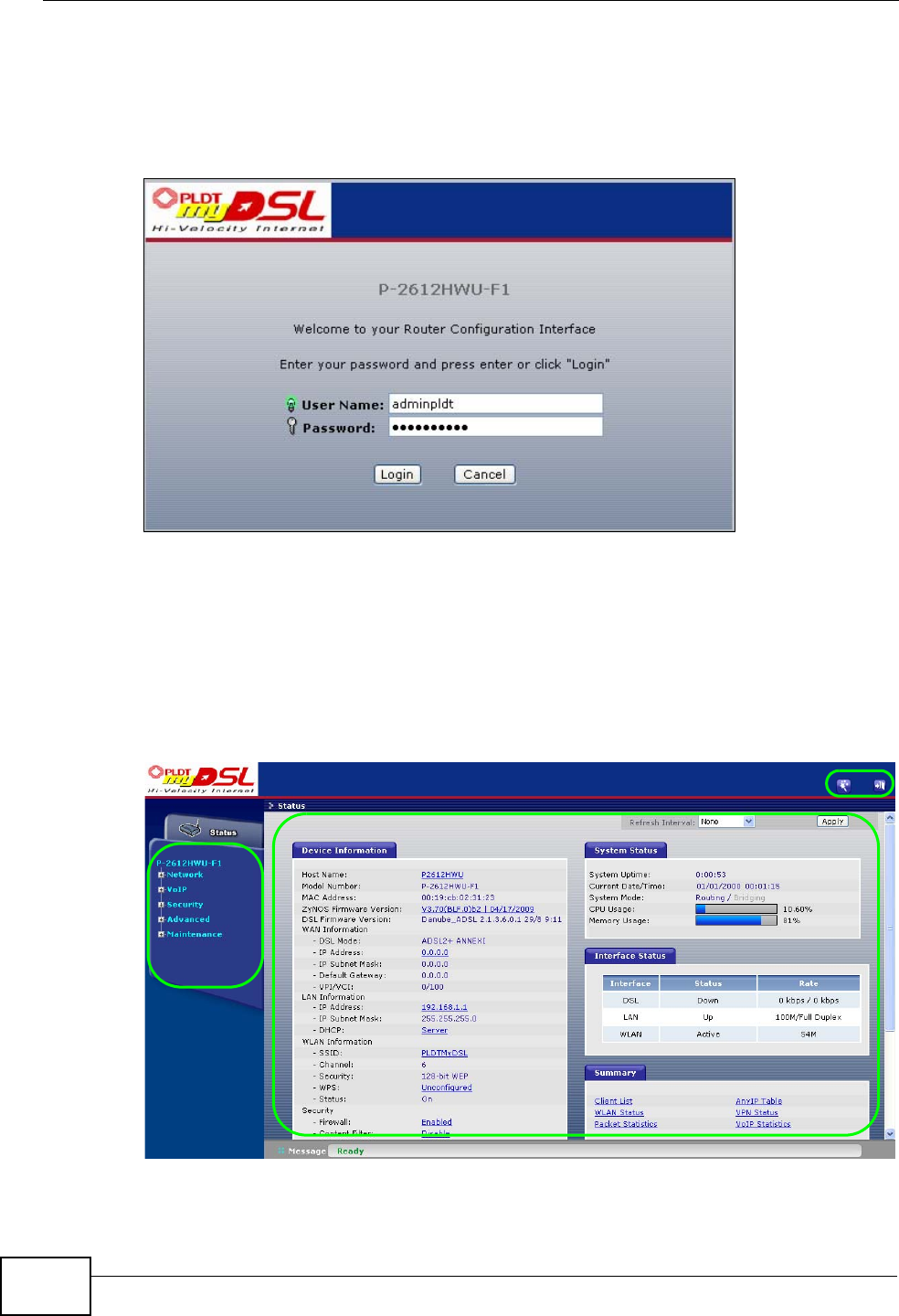
4A password screen displays. Type “adminpldt” (default) as the username and
“1234567890” as the password, and click Login. Click Cancel to revert to the
default password in the password field. If you have changed the password, enter
your password and click Login.
Figure 5 Password Screen
Note: For security reasons, the ZyXEL Device automatically logs you out if you do not
use the web configurator for five minutes (default). If this happens, log in again.
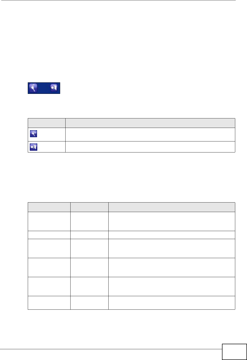
2.2 Web Configurator Main Screen
Figure 6 Main Screen
As illustrated above, the main screen is divided into these parts:
A
BC
D
Chapter 2 Introducing the Web Configurator
P-2612HWU-F1 User’s Guide 35
•A - title bar
•B - navigation panel
•C - main window
•D - status bar
2.2.1 Title Bar
The title bar allows you to change the language and provides some icons in the
upper right corner.
The icons provide the following functions.
2.2.2 Navigation Panel
Use the menu items on the navigation panel to open screens to configure ZyXEL
Device features. The following tables describe each menu item.
Table 2 Web Configurator Icons in the Title Bar
ICON DESCRIPTION
Wizards: Click this icon to go to the configuration wizards. See Chapter
3 on page 41 for more information.
Logout: Click this icon to log out of the web configurator.
Table 3 Navigation Panel Summary
LINK TAB FUNCTION
Status This screen shows the ZyXEL Device’s general device
and network status information. Use this screen to
access the statistics and client list.
Network
WAN Internet
Access Setup Use this screen to configure ISP parameters, WAN IP
address assignment, DNS servers and other advanced
properties.
LAN IP Use this screen to configure LAN TCP/IP settings,
DHCP settings, enable Any IP and configure other
advanced properties.
Client List Use this screen to view current DHCP client
information and to always assign specific IP addresses
to individual MAC addresses (and host names).
IP Alias Use this screen to partition your LAN interface into
subnets.

Chapter 2 Introducing the Web Configurator
P-2612HWU-F1 User’s Guide
36
Wireless LAN AP Use this screen to configure the wireless LAN settings
and WLAN authentication/security settings.
More AP Use this screen to configure multiple BSSs on the
ZyXEL Device.
MAC Filter Use this screen to configure the ZyXEL Device to give
exclusive access to specific wireless clients or exclude
specific wireless clients from accessing the ZyXEL
Device.
WPS Use this screen to configure multiple BSSs on the
ZyXEL Device.
WPS Station Use this screen to configure WPS (Wi-Fi Protected
Setup) settings.
WDS Use this screen to configure your WDS (Wireless
Distribution System) links between the ZyXEL Device
and other wireless APs.
Scheduling Use this screen to configure when the ZyXEL Device
enables or disables the wireless LAN.
NAT General Use this screen to use WPS to set up your wireless
network.
Port
Forwarding Use this screen to make your local servers visible to
the outside world.
Address
Mapping Use this screen to configure network address
translation mapping rules.
ALG Use this screen to enable or disable SIP ALG.
VoIP
SIP SIP Settings Use this screen to configure your ZyXEL Device’s Voice over
IP settings.
QoS Use this screen to configure your ZyXEL Device’s Quality of
Service settings for VoIP.
Phone Analog Phone Use this screen to set which phone ports use which
SIP accounts.
Ext. Table Use this screen to assign extension numbers to
phones connected to the ZyXEL Device.
Common Use this screen to configure general phone port
settings.
Region Use this screen to select your location and call service
mode.
Phone Book Speed Dial Use this screen to configure speed dial for SIP phone
numbers that you call often.
Incoming Call
Policy Use this screen to configure call-forwarding.
SIP Prefix Use this screen to set up numbers you dial on your
phone to specify which SIP account you want to use
for a call.
Security
Table 3 Navigation Panel Summary
LINK TAB FUNCTION

Chapter 2 Introducing the Web Configurator
P-2612HWU-F1 User’s Guide 37
Firewall General Use this screen to activate/deactivate the firewall and
the default action to take on network traffic going in
specific directions.
Rules This screen shows a summary of the firewall rules,
and allows you to edit/add a firewall rule.
Threshold Use this screen to configure the thresholds for
determining when to drop sessions that do not
become fully established.
Content Filter Keyword Use this screen to block access to web sites
containing certain keywords in the URL.
Schedule Use this screen to set the days and times for your
device to perform content filtering.
Trusted Use this screen to exclude a range of users on the
LAN from content filtering.
VPN Setup Use this screen to configure each VPN tunnel.
Monitor Use this screen to look at the current status of each
VPN tunnel.
VPN Global
Setting Use this screen to allow NetBIOS traffic through VPN
tunnels.
Certificates My Certificates Use this screen to generate and export self-signed
certificates or certification requests and import the
ZyXEL Device’s CA-signed certificates.
Trusted CAs Use this screen to save CA certificates to the ZyXEL
Device.
Trusted
Remote Hosts Use this screen to import self-signed certificates.
Advanced
Static Route Static Route Use this screen to configure IP static routes to tell
your device about networks beyond the directly
connected remote nodes.
802.1Q/1P Group Setting Use this screen to activate 802.1Q/1P, specify the
management VLAN group, display the VLAN groups and
configure the settings for each VLAN group.
Port Setting Use this screen to configure the PVID and assign traffic
priority for each port.
QoS General Use this screen to enable QoS and traffic prioritizing,
and configure bandwidth management on the WAN.
Class Setup Use this screen to define a classifier.
Monitor Use this screen to view each queue’s statistics.
Dynamic DNS Dynamic DNS This screen allows you to use a static hostname alias
for a dynamic IP address.
Table 3 Navigation Panel Summary
LINK TAB FUNCTION
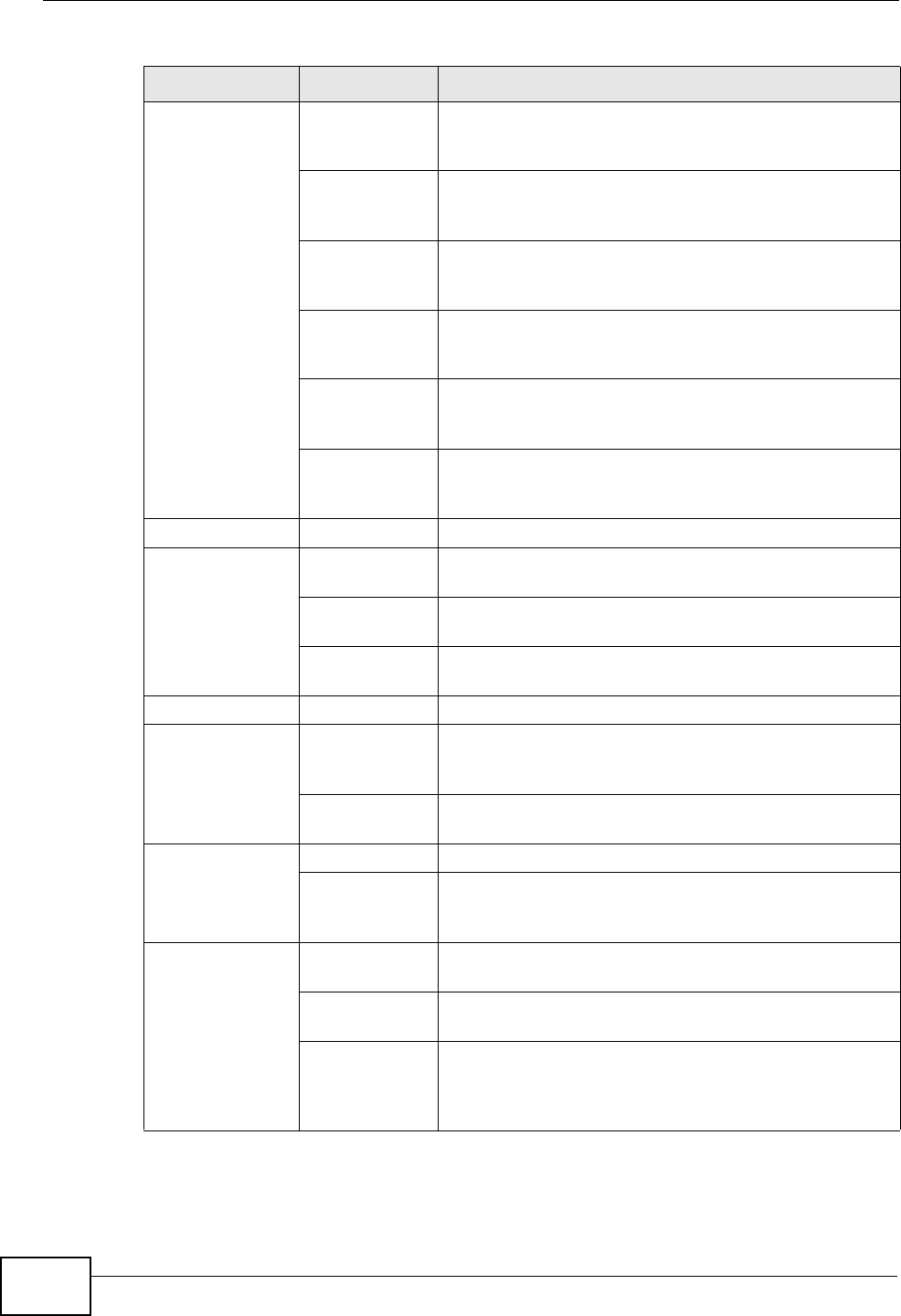
Chapter 2 Introducing the Web Configurator
P-2612HWU-F1 User’s Guide
38
Remote
MGMT HTTP Use this screen to configure through which
interface(s) and from which IP address(es) users can
use HTTP to manage the ZyXEL Device.
Telnet Use this screen to configure through which
interface(s) and from which IP address(es) users can
use Telnet to manage the ZyXEL Device.
FTP Use this screen to configure through which
interface(s) and from which IP address(es) users can
use FTP to access the ZyXEL Device.
SNMP Use this screen to configure your ZyXEL Device’s
settings for Simple Network Management Protocol
management.
DNS Use this screen to configure through which
interface(s) and from which IP address(es) users can
send DNS queries to the ZyXEL Device.
ICMP Use this screen to set whether or not your device will
respond to pings and probes for services that you
have not made available.
UPnP General Use this screen to turn UPnP on or off.
File Sharing Server Setting Use this screen to enable file sharing via the ZyXEL
Device.
User Name
and Password Use this screen to setup a user’s name and password
for secure access to your shared files.
Share
Configuration Use this screen to view or configure the share
directories (folders) on the ZyXEL Device.
Maintenance
System General Use this screen to configure your device’s name,
domain name, management inactivity timeout and
password.
Time Setting Use this screen to change your ZyXEL Device’s time
and date.
Logs View Log Use this screen to display your device’s logs.
Log Settings Use this screen to select which logs and/or immediate
alerts your device is to record. You can also set it to e-
mail the logs to you.
Call History Summary Use this screen to view call history summary of a
certain period.
Call History Use this screen to view the details of the calls
performed on the ZyXEL Device.
Call History
Settings Use this screen to configure to where the ZyXEL
Device is to send call records and the schedule for
when the ZyXEL Device is to send or save the call
records.
Table 3 Navigation Panel Summary
LINK TAB FUNCTION

Chapter 2 Introducing the Web Configurator
P-2612HWU-F1 User’s Guide 39
2.2.3 Main Window
The main window displays information and configuration fields. It is discussed in
the rest of this document.
Right after you log in, the Status screen is displayed. See Chapter 5 on page 91
for more information about the Status screen.
2.2.4 Status Bar
Check the status bar when you click Apply or OK to verify that the configuration
has been updated.
Tools Firmware Use this screen to upload firmware to your device.
Configuration Use this screen to backup and restore your device’s
configuration (settings) or reset the factory default
settings.
Restart This screen allows you to reboot the ZyXEL Device
without turning the power off.
Diagnostic General Use this screen to test the connections to other
devices.
Table 3 Navigation Panel Summary
LINK TAB FUNCTION

Chapter 2 Introducing the Web Configurator
P-2612HWU-F1 User’s Guide
40
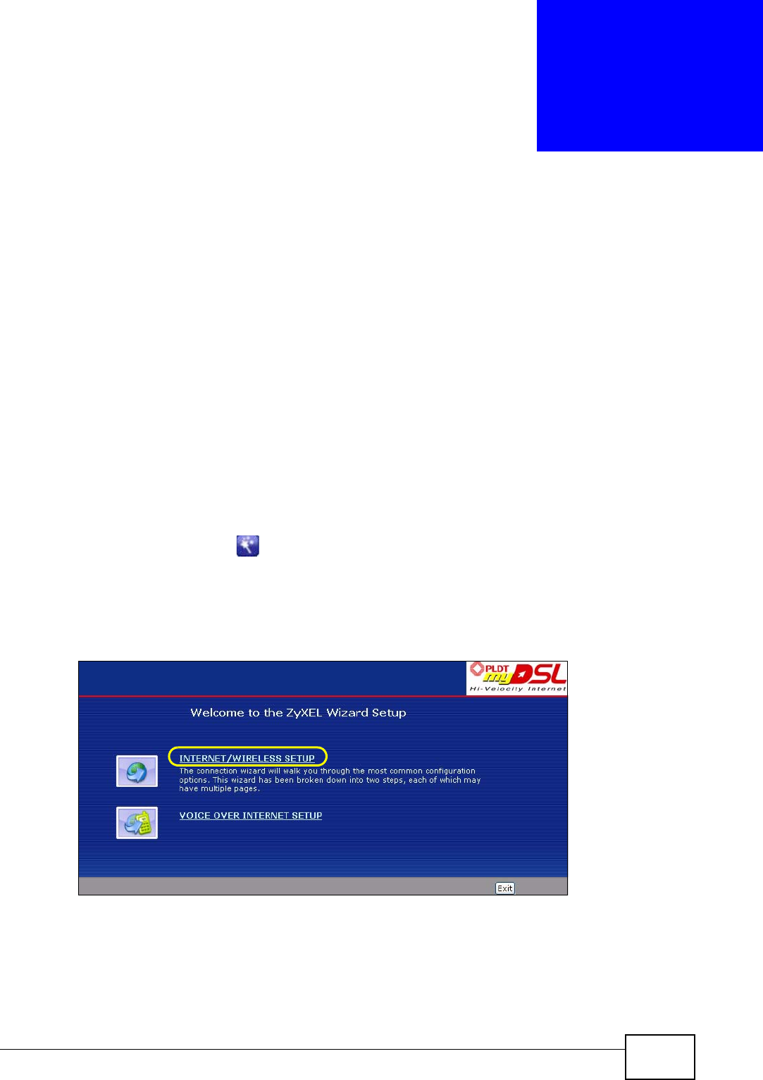
P-2612HWU-F1 User’s Guide 41
CHAPTER 3
Wizards
3.1 Overview
Use the wizard setup screens to configure your system for Internet access,
wireless, and making calls over the Internet with the information given to you by
your ISP.
Note: See the advanced menu chapters for background information on these fields.
3.2 Internet Access Wizard Setup
1Click the wizard icon ( ) in the top right corner of the web configurator to go to
the wizards.
2Click INTERNET/WIRELESS SETUP to configure the system for Internet access
and wireless connection.
Figure 7 Wizard Welcome
3Your ZyXEL Device attempts to detect your DSL connection and your connection
type.
3a The following screen appears if a connection is not detected. Check your
hardware connections and click Restart the INTERNET/WIRELESS SETUP
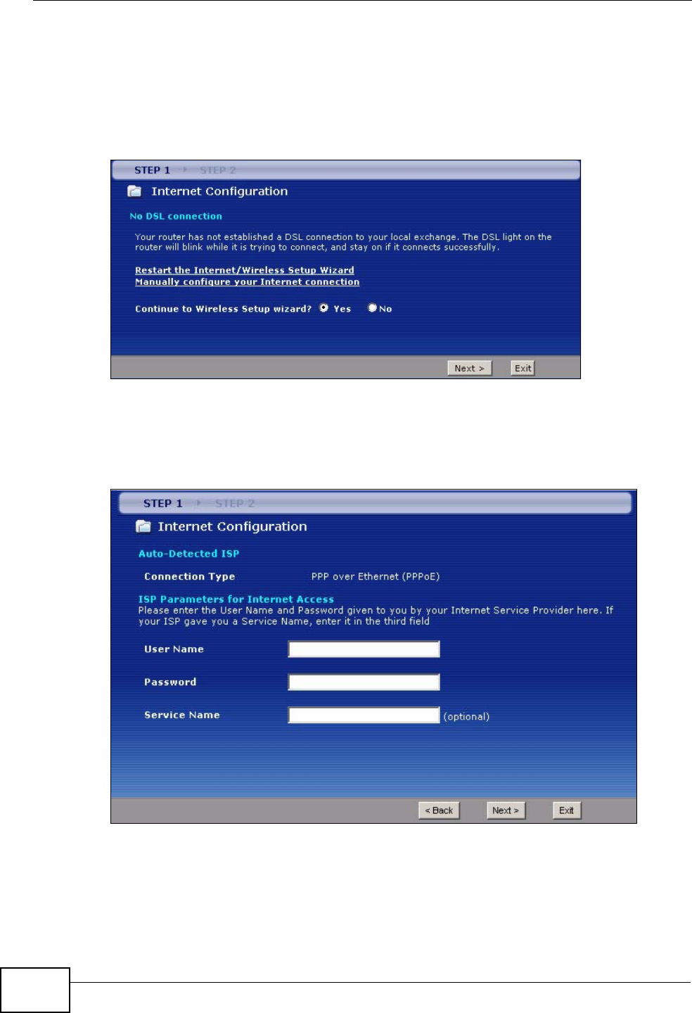
Chapter 3 Wizards
P-2612HWU-F1 User’s Guide
42
Wizard to return to the wizard welcome screen. If you still cannot connect,
click Manually configure your Internet connection. Follow the directions
in the wizard and enter your Internet setup information as provided to you by
your ISP. See Section 3.2.1 on page 44 for more details.
If you would like to skip your Internet setup and configure the wireless LAN
settings, leave Yes selected and click Next.
Figure 8 Auto Detection: No DSL Connection
3b The following screen displays if a PPPoE or PPPoA connection is detected.
Enter your Internet account information (username, password and/or service
name) exactly as provided by your ISP. Then click Next and see Section 3.3
on page 49 for wireless connection wizard setup.
Figure 9 Auto-Detection: PPPoE
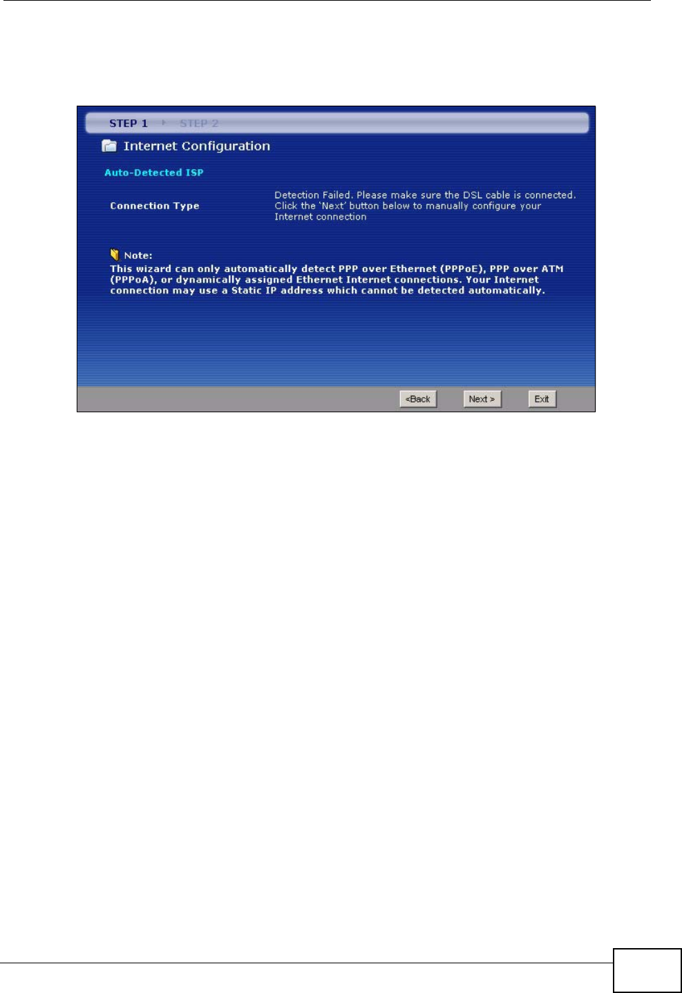
Chapter 3 Wizards
P-2612HWU-F1 User’s Guide 43
3c The following screen appears if the ZyXEL device detects a connection but not
the connection type. Click Next and refer to Section 3.2.1 on page 44 on how
to manually configure the ZyXEL Device for Internet access.
Figure 10 Auto Detection: Failed
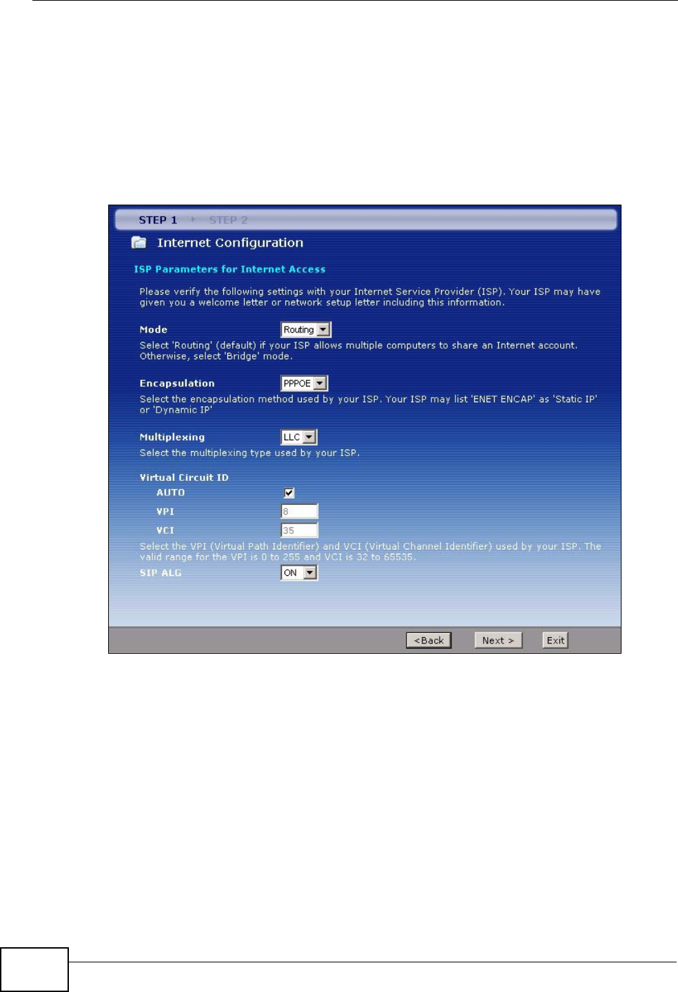
Chapter 3 Wizards
P-2612HWU-F1 User’s Guide
44
3.2.1 Manual Configuration
1If the ZyXEL Device fails to detect your DSL connection type but the physical line
is connected, enter your Internet access information in the wizard screen exactly
as your service provider gave it to you. Leave the defaults in any fields for which
you were not given information. This wizard screen varies depending on the WAN
mode you set using the DSL/WAN switch on the back of the ZyXEL Device.
Figure 11 Internet Access Wizard Setup: ISP Parameters (DSL WAN)
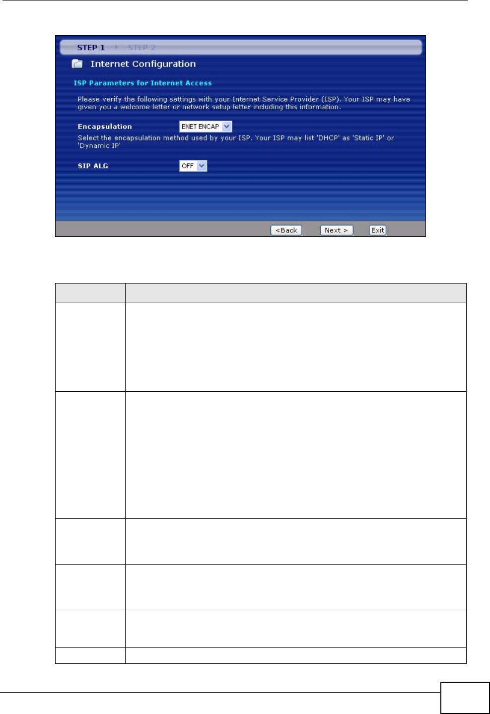
Chapter 3 Wizards
P-2612HWU-F1 User’s Guide 45
Figure 12 Internet Access Wizard Setup: ISP Parameters (Ethernet WAN)
The following table describes the fields in this screen.
Table 4 Internet Access Wizard Setup: ISP Parameters
LABEL DESCRIPTION
Mode This field is not available if you set the WAN mode to Ethernet WAN.
Select Routing (default) from the drop-down list box if your ISP give you
one IP address only and you want multiple computers to share an Internet
account. Select Bridge when your ISP provides you more than one IP
address and you want the connected computers to get individual IP
address from ISP’s DHCP server directly. If you select Bridge, you cannot
use Firewall, DHCP server and NAT on the ZyXEL Device.
Encapsulation Select the encapsulation type your ISP uses from the Encapsulation
drop-down list box. Choices vary depending on what you select in the
Mode field.
If you set the WAN mode to DSL WAN and select Bridge in the Mode
field, select PPPoA or RFC 1483.
If you set the WAN mode to DSL WAN and select Routing in the Mode
field, select PPPoA, ENET ENCAP or PPPoE.
If you set the WAN mode to Ethernet WAN, select ENET ENCAP or
PPPoE.
Multiplexing This field is not available if you set the WAN mode to Ethernet WAN.
Select the method of multiplexing used by your ISP from the drop-down
list. Choices are VC or LLC.
Virtual Circuit
ID This field is not available if you set the WAN mode to Ethernet WAN.
VPI (Virtual Path Identifier) and VCI (Virtual Channel Identifier) define a
virtual circuit. Refer to the appendix for more information.
AUTO Select the check box to use the default VPI and VCI (8 and 35).
Otherwise, clear the check box and enter the VPI and VCI manually in the
fields below.
VPI Enter the VPI assigned to you. This field may already be configured.
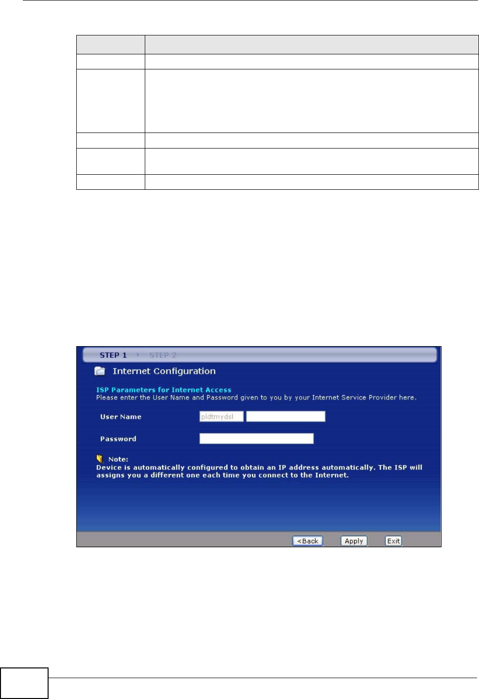
Chapter 3 Wizards
P-2612HWU-F1 User’s Guide
46
2The next wizard screen varies depending on what mode and encapsulation type
you use. All screens shown are with routing mode. Configure the fields and click
Next to continue. See Section 3.3 on page 49 for wireless connection wizard
setup.
Note: When you use the connection wizard to configure the Internet access using
PPPoE or PPPoA, the ZyXEL Device is set to get an IP address from the ISP
automatically. To set up a static WAN IP address with PPPoE or PPPoA, use
the Network > WAN screen.
Figure 13 Internet Connection with PPPoE or PPPoA
VCI Enter the VCI assigned to you. This field may already be configured.
SIP ALG This field is not available when you select Bridge in the Mode field.
Select ON to enable the SIP ALG in the ZyXEL Device and allow SIP calls
to pass through NAT.
Select OFF to disable the SIP ALG in the ZyXEL Device.
Back Click Back to go back to the previous screen.
Next Click Next to continue to the next wizard screen. The next wizard screen
you see depends on what protocol you chose above.
Exit Click Exit to close the wizard screen without saving your changes.
Table 4 Internet Access Wizard Setup: ISP Parameters
LABEL DESCRIPTION
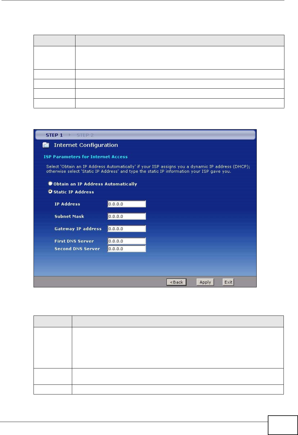
Chapter 3 Wizards
P-2612HWU-F1 User’s Guide 47
The following table describes the fields in this screen.
Figure 14 Internet Connection with DHCP (ENET ENCAP)
The following table describes the fields in this screen.
Table 5 Internet Connection with PPPoE or PPPoA
LABEL DESCRIPTION
User Name Enter the user name exactly as your ISP assigned. If assigned a name in
the form user@domain where domain identifies a service name, then enter
both components exactly as given.
Password Enter the password associated with the user name above.
Back Click Back to go back to the previous wizard screen.
Apply Click Apply to save your changes back to the ZyXEL Device.
Exit Click Exit to close the wizard screen without saving your changes.
Table 6 Internet Connection with DHCP (ENET ENCAP)
LABEL DESCRIPTION
Obtain an IP
Address
Automatical
ly
A static IP address is a fixed IP that your ISP gives you. A dynamic IP
address is not fixed; the ISP assigns you a different one each time you
connect to the Internet.
Select Obtain an IP Address Automatically if you have a dynamic IP
address.
Static IP
Address Select Static IP Address if your ISP gave you an IP address to use.
IP Address Enter your ISP assigned IP address.
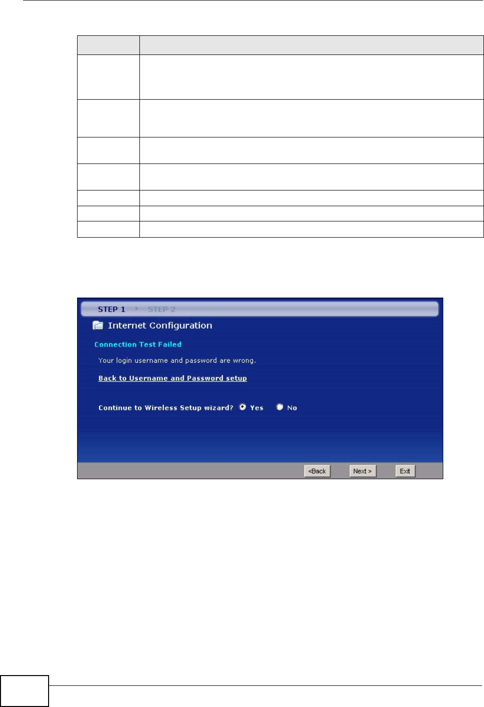
Chapter 3 Wizards
P-2612HWU-F1 User’s Guide
48
• If the user name and/or password you entered for PPPoE connection are not
correct, the screen displays as shown next. Click Back to Username and
Password setup to go back to the screen where you can modify them.
Figure 15 Connection Test Failed-1
Subnet
Mask Enter a subnet mask in dotted decimal notation.
Refer to the appendix to calculate a subnet mask If you are implementing
subnetting.
Gateway IP
address You must specify a gateway IP address (supplied by your ISP) when you
use ENET ENCAP (DHCP) in the Encapsulation field in the previous
screen.
First DNS
Server Enter the IP addresses of the DNS servers. The DNS servers are passed to
the DHCP clients along with the IP address and the subnet mask.
Second DNS
Server As above.
Back Click Back to go back to the previous wizard screen.
Apply Click Apply to save your changes back to the ZyXEL Device.
Exit Click Exit to close the wizard screen without saving your changes.
Table 6 Internet Connection with DHCP (ENET ENCAP) (continued)
LABEL DESCRIPTION
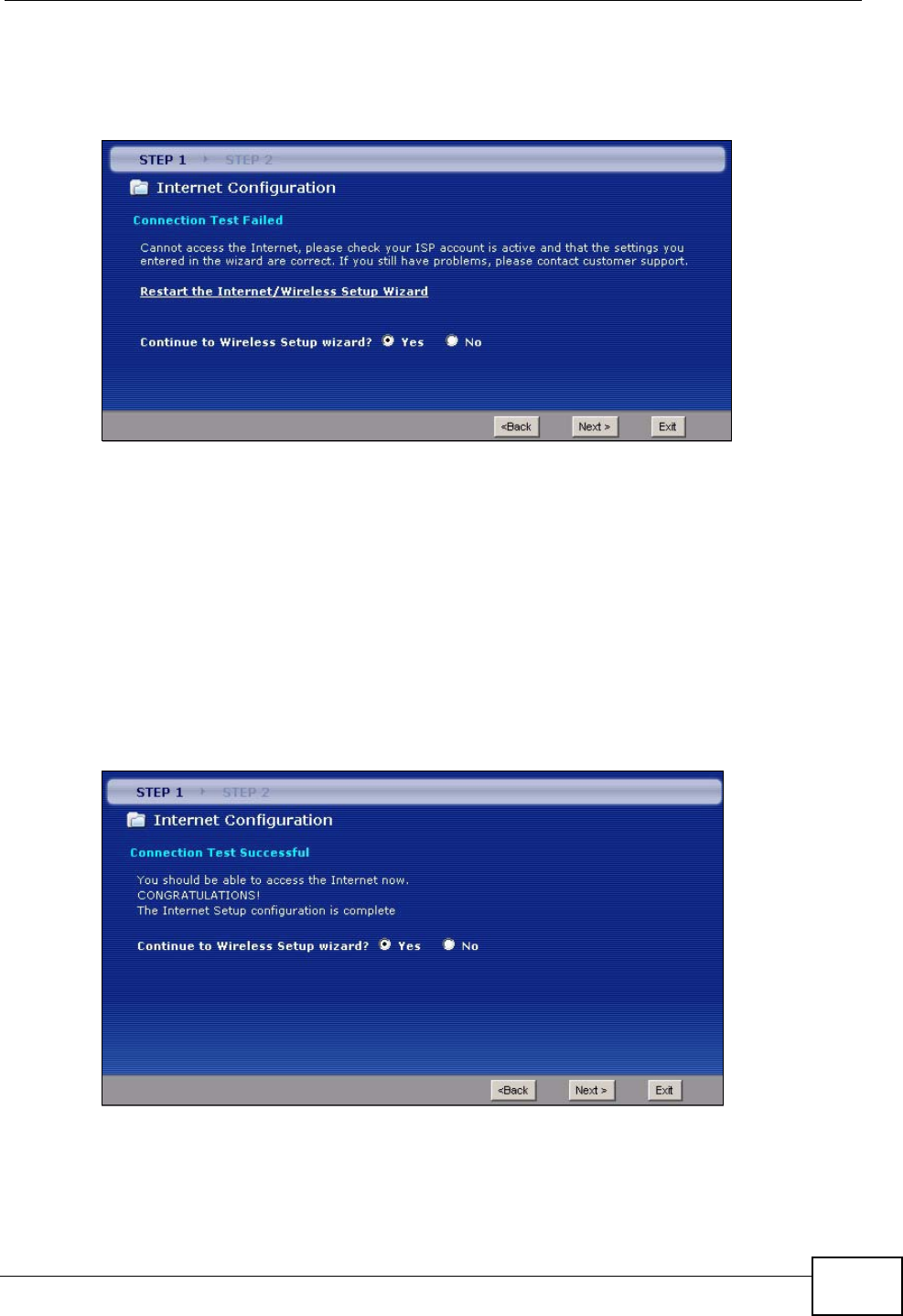
Chapter 3 Wizards
P-2612HWU-F1 User’s Guide 49
• If the following screen displays, check if your account is activated or click
Restart the Internet/Wireless Setup Wizard to verify your Internet access
settings.
Figure 16 Connection Test Failed-2.
3.3 Wireless Connection Wizard Setup
See the back panel for the ZyXEL Device’s unique wireless SSID (network name)
and WPA-PSK encryption key. Unless you want to use other wireless settings, you
can close the wizard after you configure the Internet connection.
1Select Yes and click Next to configure wireless settings. Otherwise, select No and
skip to Step 6.
Figure 17 Connection Test Successful
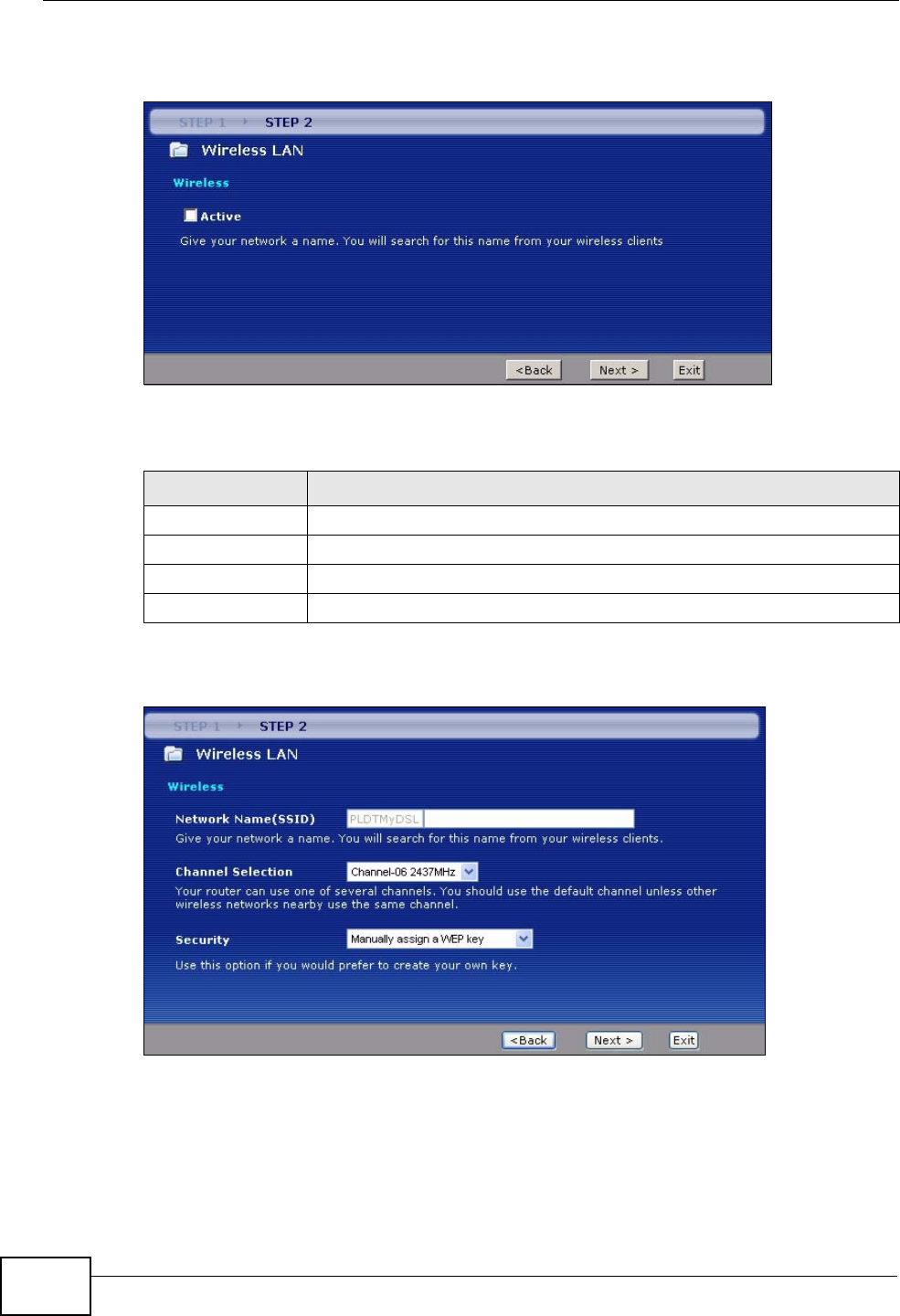
Chapter 3 Wizards
P-2612HWU-F1 User’s Guide
50
2Use this screen to activate the wireless LAN. Click Next to continue.
Figure 18 Wireless LAN Setup Wizard 1
The following table describes the labels in this screen.
3Configure your wireless settings in this screen. Click Next.
Figure 19 Wireless LAN
Table 7 Wireless LAN Setup Wizard 1
LABEL DESCRIPTION
Active Select the check box to turn on the wireless LAN.
Back Click Back to display the previous screen.
Next Click Next to proceed to the next screen.
Exit Click Exit to close the wizard screen without saving.

Chapter 3 Wizards
P-2612HWU-F1 User’s Guide 51
The following table describes the labels in this screen.
Note: The wireless stations and ZyXEL Device must use the same SSID, channel ID
and WEP encryption key (if WEP is enabled), WPA-PSK (if WPA-PSK is
enabled) for wireless communication.
4This screen varies depending on the security mode you selected in the previous
screen. Fill in the field (if available) and click Next.
Table 8 Wireless LAN Setup Wizard 2
LABEL DESCRIPTION
Network
Name(SSID) Enter a descriptive name (up to 32 printable 7-bit ASCII characters) for the
wireless LAN.
If you change this field on the ZyXEL Device, make sure all wireless
stations use the same SSID in order to access the network.
Channel
Selection The range of radio frequencies used by IEEE 802.11b/g wireless devices is
called a channel. Select a channel ID that is not already in use by a
neighboring device.
Security Select Manually assign a WPA-PSK key to configure a Pre-Shared Key
(WPA-PSK). Choose this option only if your wireless clients support WPA.
See Section 3.3.1 on page 52 for more information.
Select Manually assign a WEP key to configure a WEP Key. See Section
3.3.2 on page 53 for more information.
Select Disable wireless security to have no wireless LAN security
configured and your network is accessible to any wireless networking
device that is within range.
Back Click Back to display the previous screen.
Next Click Next to proceed to the next screen.
Exit Click Exit to close the wizard screen without saving.
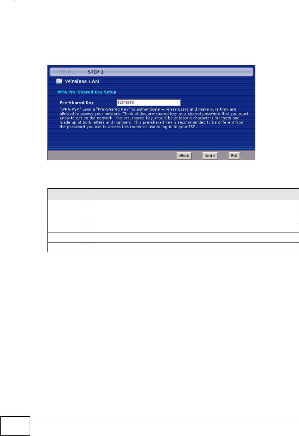
Chapter 3 Wizards
P-2612HWU-F1 User’s Guide
52
3.3.1 Manually Assign a WPA-PSK key
Choose Manually assign a WPA-PSK key in the Wireless LAN setup screen to
set up a Pre-Shared Key.
Figure 20 Manually Assign a WPA-PSK key
The following table describes the labels in this screen.
Table 9 Manually Assign a WPA key
LABEL DESCRIPTION
Pre-Shared
Key Type from 8 to 63 case-sensitive ASCII characters. You can set up the most
secure wireless connection by configuring WPA in the wireless LAN screens.
You need to configure an authentication server to do this.
Back Click Back to display the previous screen.
Next Click Next to proceed to the next screen.
Exit Click Exit to close the wizard screen without saving.
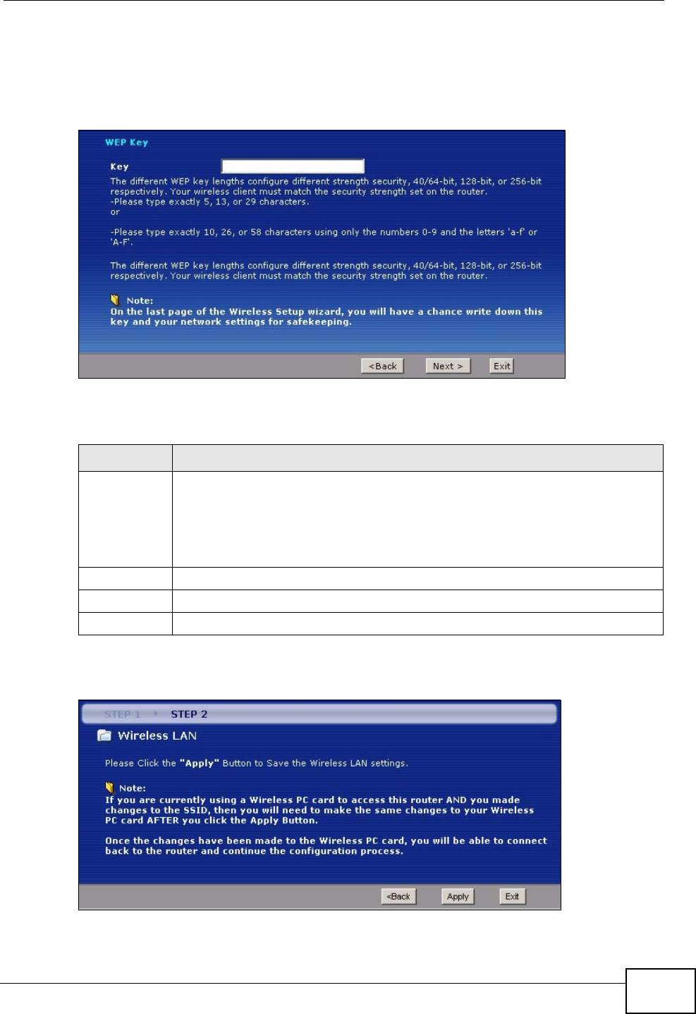
Chapter 3 Wizards
P-2612HWU-F1 User’s Guide 53
3.3.2 Manually Assign a WEP Key
Choose Manually assign a WEP key to setup WEP Encryption parameters.
Figure 21 Manually Assign a WEP key
The following table describes the labels in this screen.
5Click Apply to save your wireless LAN settings.
Figure 22 Wireless LAN Setup 3
Table 10 Manually Assign a WEP key
LABEL DESCRIPTION
Key The WEP keys are used to encrypt data. Both the ZyXEL Device and the
wireless stations must use the same WEP key for data transmission.
Enter any 5, 13 or 29 ASCII characters or 10, 26 or 58 hexadecimal
characters ("0-9", "A-F") for a 64-bit, 128-bit or 256-bit WEP key
respectively.
Back Click Back to display the previous screen.
Next Click Next to proceed to the next screen.
Exit Click Exit to close the wizard screen without saving.
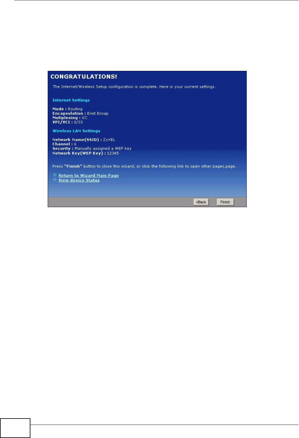
Chapter 3 Wizards
P-2612HWU-F1 User’s Guide
54
6Use the read-only summary table to check whether what you have configured is
correct. Click Finish to complete and save the wizard setup.
Note: No wireless LAN settings display if you chose not to configure wireless LAN
settings.
Figure 23 Internet Access and WLAN Wizard Setup Complete
7Launch your web browser and navigate to www.zyxel.com. Internet access is just
the beginning. Refer to the rest of this guide for more detailed information on the
complete range of ZyXEL Device features. If you cannot access the Internet, open
the web configurator again to confirm that the Internet settings you configured in
the wizard setup are correct.
3.4 VoIP Setup Wizard
Use this wizard to set up your VoIP account(s). Leave the default settings in fields
if your VoIP service provider (the company that lets you make phone calls over the
Internet) did not provide any information. See Chapter 10 on page 181 and
Chapter 11 on page 217 for more information.
Note: You must have a SIP account before you can use this wizard.
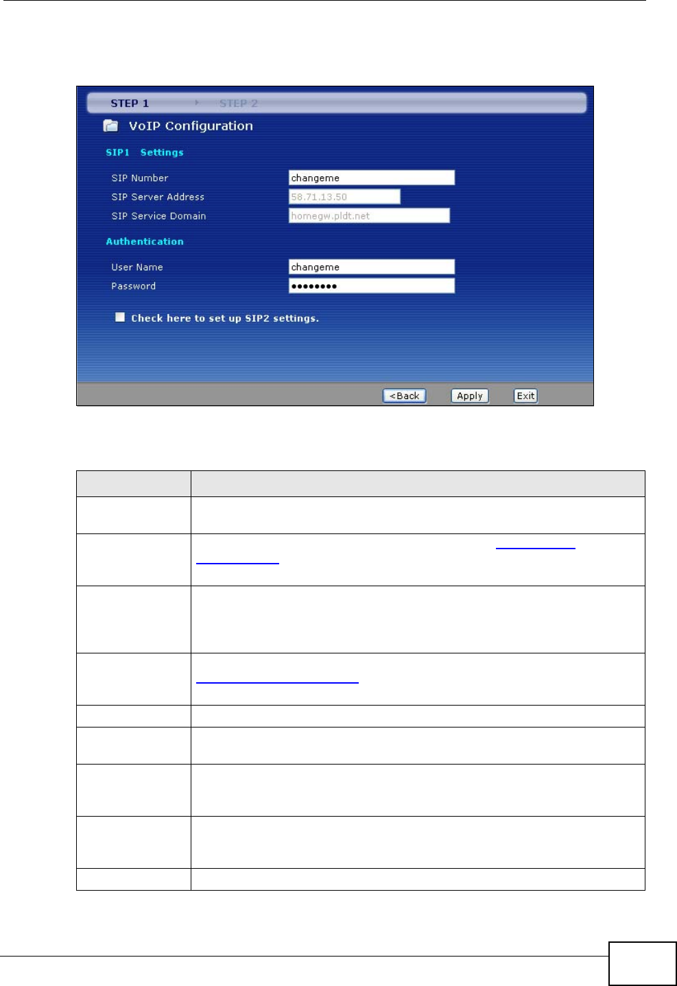
Chapter 3 Wizards
P-2612HWU-F1 User’s Guide 55
3.4.1 SIP Settings
Figure 24 VoIP Setup Wizard > SIP Settings
The following table describes the labels in this screen.
Table 11 VoIP Setup Wizard > SIP Settings
LABEL DESCRIPTION
SIP1 (- SIP10)
Settings Use this screen to configure SIP settings for up to 10 SIP accounts.
SIP Number Enter your SIP number. In the full SIP URI (like 1234@VoIP-
provider.com), this is the part before the @ symbol. You can use up to
127 printable ASCII characters.
SIP Server
Address Enter the IP address or domain name of the SIP server provided by
your VoIP service provider. You can use up to 95 printable ASCII
characters. It does not matter whether the SIP server is a proxy,
redirect or register server.
SIP Service
Domain Enter the SIP service domain name. In the full SIP URI (like
1234@VoIP-provider.com), this is the part after the @ symbol. You
can use up to 127 printable ASCII Extended set characters.
Authentication
User Name Enter the user name for registering this SIP account, exactly as it was
given to you. You can use up to 95 printable ASCII characters.
Password Enter the user name for registering this SIP account, exactly as it was
given to you. You can use up to 95 printable ASCII Extended set
characters.
Check here to
set up SIP 2
settings
Select this if you want to set up additional SIP accounts.
< Back Click this to go to the previous screen.
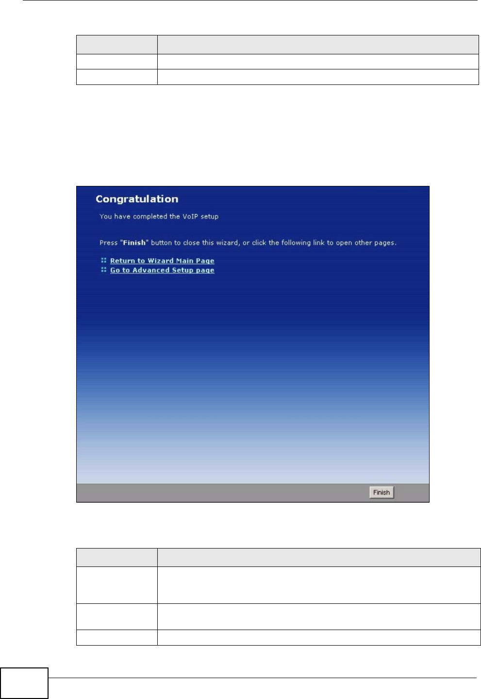
Chapter 3 Wizards
P-2612HWU-F1 User’s Guide
56
3.4.2 Registration Complete
This screen depends on whether or not the ZyXEL Device successfully registered
your SIP account(s).
Figure 25 VoIP Setup Wizard > Registration Complete (Success)
The following table describes the labels in this screen.
Apply Click this to register your SIP account(s).
Exit Click this to close this screen and return to the main screen.
Table 11 VoIP Setup Wizard > SIP Settings
LABEL DESCRIPTION
Table 12 VoIP Setup Wizard > Registration Complete (Success)
LABEL DESCRIPTION
Return to
Wizard Main
Page
Click this to open the main wizard screen. See Section 3.2 on page 41.
Go to Advanced
Setup page Click this to close this screen and return to the main screen.
Finish Click this to close this screen and return to the main screen.
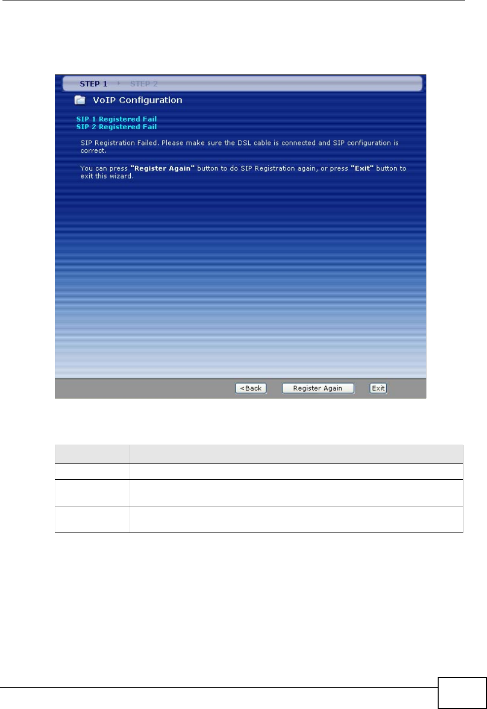
Chapter 3 Wizards
P-2612HWU-F1 User’s Guide 57
If the ZyXEL Device cannot register your SIP account(s), see the Quick Start
Guide for troubleshooting suggestions.
Figure 26 VoIP Setup Wizard > Registration Complete (Fail)
The following table describes the labels in this screen.
Table 13 VoIP Setup Wizard > Registration Complete (Fail)
LABEL DESCRIPTION
< Back Click this to go to the previous screen.
Register Again Click this if you want the ZyXEL Device to try to register your SIP
account(s) again.
Exit Click this to close this screen and return to the main screen. The ZyXEL
Device saves the information you provided.

Chapter 3 Wizards
P-2612HWU-F1 User’s Guide
58

P-2612HWU-F1 User’s Guide 59
CHAPTER 4
Tutorial
4.1 Overview
This chapter describes:
• how to set up a wireless network.
• how to use NAT with multiple public IP addresses.
• how to use NAT with multiple game players.
• how to make a VoIP call.
4.2 How to Set up a Wireless Network
This section gives you examples of how to set up an access point and wireless
client for wireless communication using the following parameters. The wireless
clients can access the Internet through the ZyXEL Device wirelessly.
4.2.1 Example Parameters
An access point (AP) or wireless router is referred to as the “AP” and a computer
with a wireless network card or USB adapter is referred to as the “wireless client”
here.
The M-302 utility screens are used here as an example. The screens may vary
slightly for different models.
SSID SSID_Example3
Security WPA-PSK
(Pre-Shared Key: ThisismyWPA-PSKpre-sharedkey)
802.11 mode Mixed (IEEE 802.11b/g)
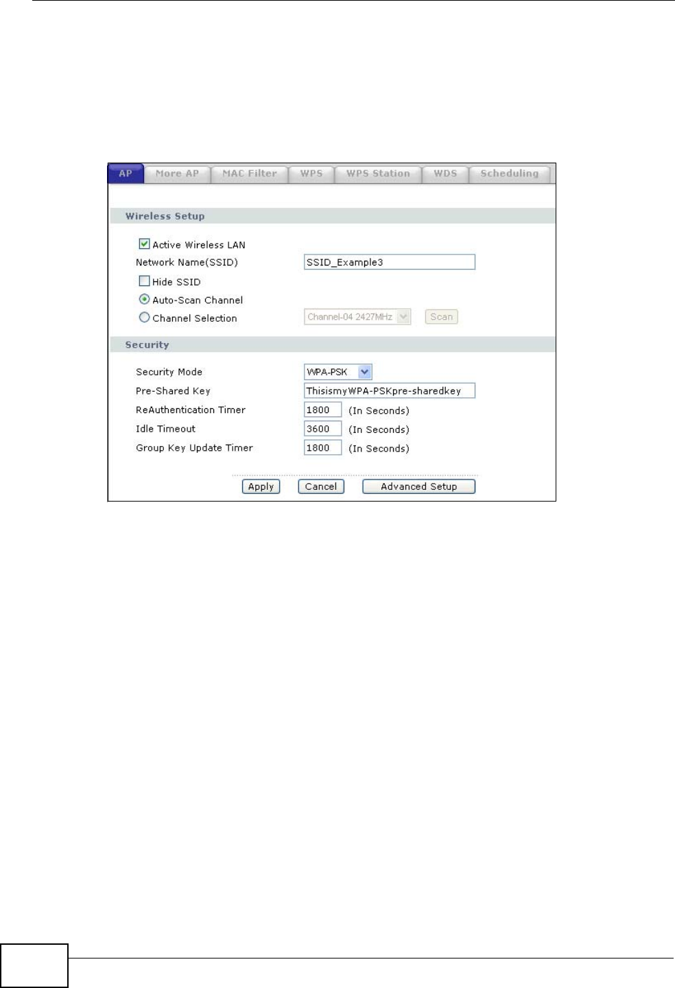
Chapter 4 Tutorial
P-2612HWU-F1 User’s Guide
60
4.2.2 Configuring the AP
Follow the steps below to configure the wireless settings on your AP.
1Open the Network > Wireless LAN > AP screen in the AP’s web configurator.
Figure 27 AP: Wireless LAN > AP
2Make sure Active Wireless LAN is selected.
3Enter “SSID_Example3” as the SSID and select a channel which is not used by
another AP.
4Set security mode to WPA-PSK and enter “ThisismyWPA-PSKpre-sharedkey” in
the Pre-Shared Key field. Click Apply.
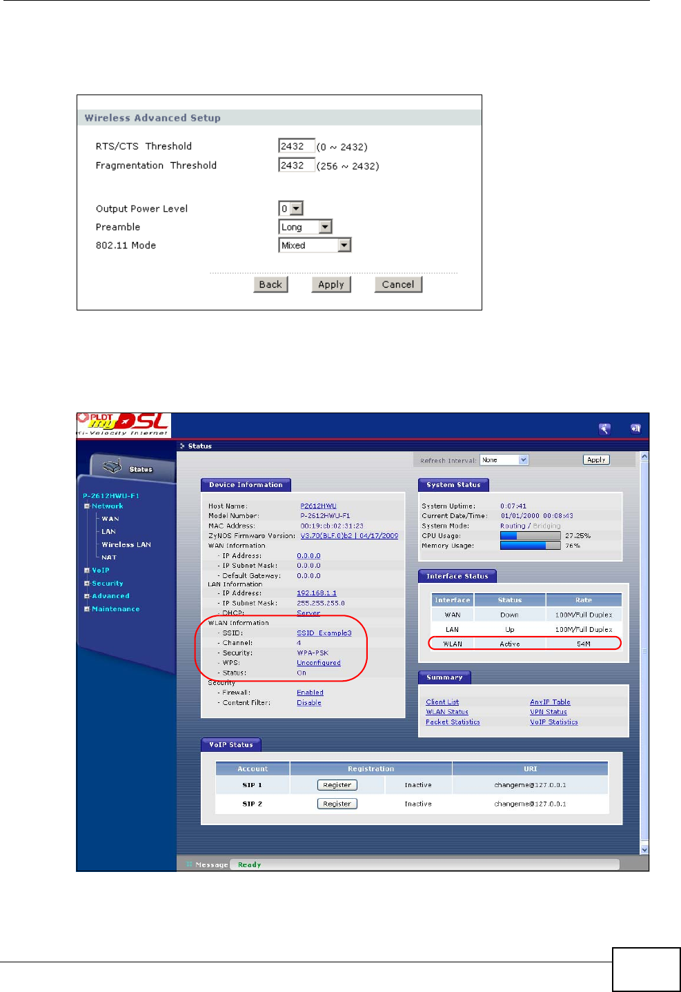
Chapter 4 Tutorial
P-2612HWU-F1 User’s Guide 61
5Click the Advanced Setup button and select Mixed in the 802.11 Mode field.
Click Apply.
Figure 28 AP: Wireless LAN > AP > Advanced Setup
6Open the Status screen. Verify your wireless and wireless security settings under
Device Information and check if the WLAN connection is up under Interface
Status.
Figure 29 AP: Status
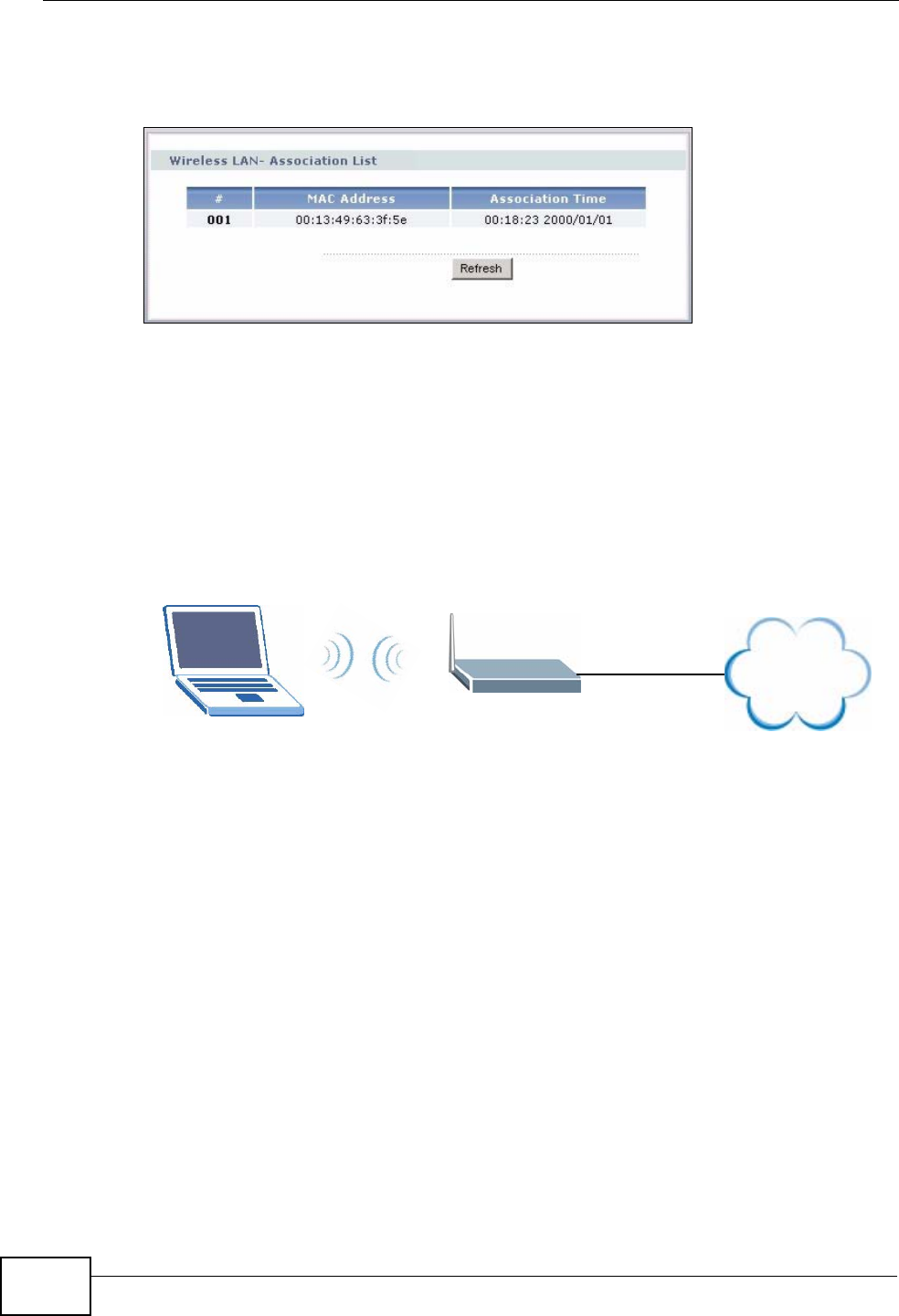
Chapter 4 Tutorial
P-2612HWU-F1 User’s Guide
62
7Click the WLAN Status hyperlink in the AP’s Status screen. You can see if any
wireless client has connected to the AP.
Figure 30 AP: Status: WLAN Station Status
4.2.3 Configuring the Wireless Client
This section describes how to connect the wireless client to a network.
4.2.3.1 Connecting to a Wireless LAN
The following sections show you how to join a wireless network using the ZyXEL
utility, as in the following diagram. The wireless client is labeled C and the access
point is labeled AP.
There are three ways to connect the client to an access point.
• Configure nothing and leave the wireless client to automatically scan for and
connect to any available network that has no wireless security configured.
• Manually connect to a network.
• Configure a profile to have the wireless client automatically connect to a specific
network or peer computer.
This example illustrates how to manually connect your wireless client to an access
point (AP) which is configured for WPA-PSK security and connected to the
Internet. Before you connect to the access point, you must know its Service Set
IDentity (SSID) and WPA-PSK pre-shared key. In this example, the SSID is
“SSID_Example3” and the pre-shared key is “ThisismyWPA-PSKpre-sharedkey”.
After you install the ZyXEL utility and then insert the wireless client, follow the
steps below to connect to a network using the Site Survey screen.
CAP
Internet
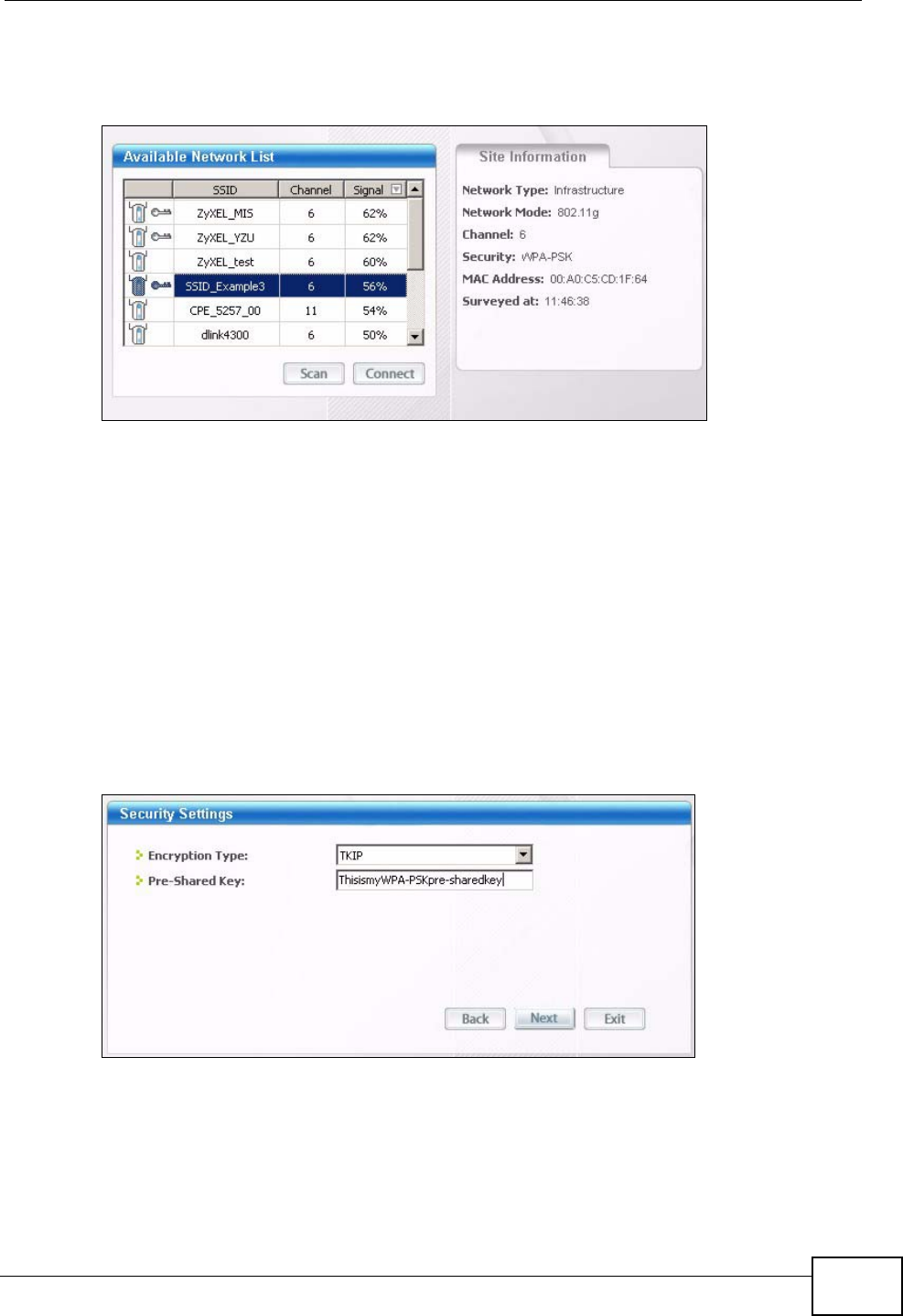
Chapter 4 Tutorial
P-2612HWU-F1 User’s Guide 63
1Open the ZyXEL utility and click the Site Survey tab to open the screen shown
next.
Figure 31 ZyXEL Utility: Site Survey
2The wireless client automatically searches for available wireless networks. Click
Scan if you want to search again. If no entry displays in the Available Network
List, that means there is no wireless network available within range. Make sure
the AP or peer computer is turned on or move the wireless client closer to the AP
or peer computer.
3When you try to connect to an AP with security configured, a window will pop up
prompting you to specify the security settings. Enter the pre-shared key and leave
the encryption type at the default setting.
Use the Next button to move on to the next screen. You can use the Back button
at any time to return to the previous screen, or the Exit button to return to the
Site Survey screen.
Figure 32 ZyXEL Utility: Security Settings
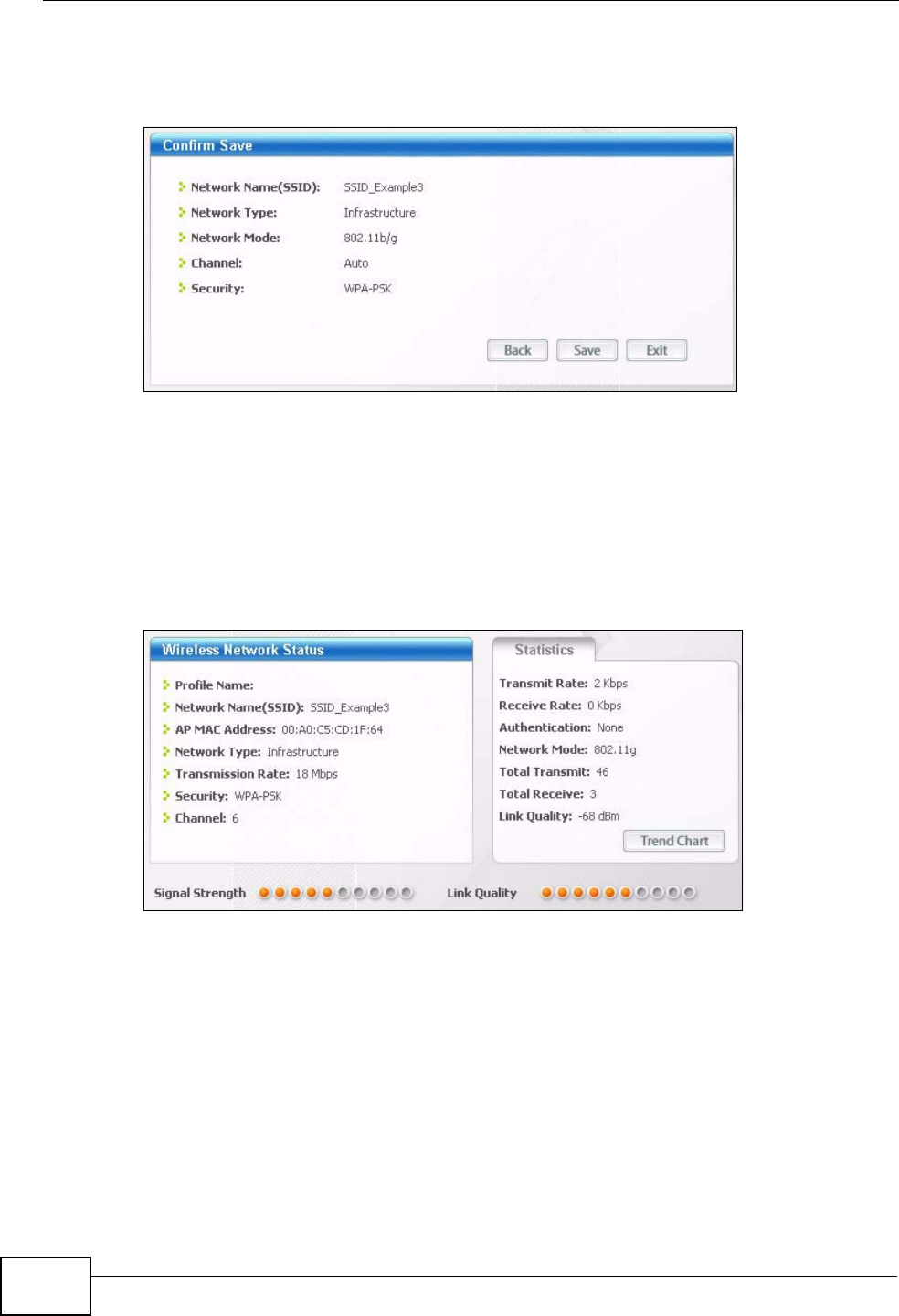
Chapter 4 Tutorial
P-2612HWU-F1 User’s Guide
64
4The Confirm Save window appears. Check your settings and click Save to
continue.
Figure 33 ZyXEL Utility: Confirm Save
5The ZyXEL utility returns to the Link Info screen while it connects to the wireless
network using your settings. When the wireless link is established, the ZyXEL
utility icon in the system tray turns green and the Link Info screen displays
details of the active connection. Check the network information in the Link Info
screen to verify that you have successfully connected to the selected network. If
the wireless client is not connected to a network, the fields in this screen remain
blank.
Figure 34 ZyXEL Utility: Link Info
6Open your Internet browser and enter http://www.zyxel.com or the URL of any
other web site in the address bar. If you are able to access the web site, your
wireless connection is successfully configured.
If you cannot access the web site, try changing the encryption type in the
Security Settings screen, check the Troubleshooting section of this User's Guide
or contact your network administrator.
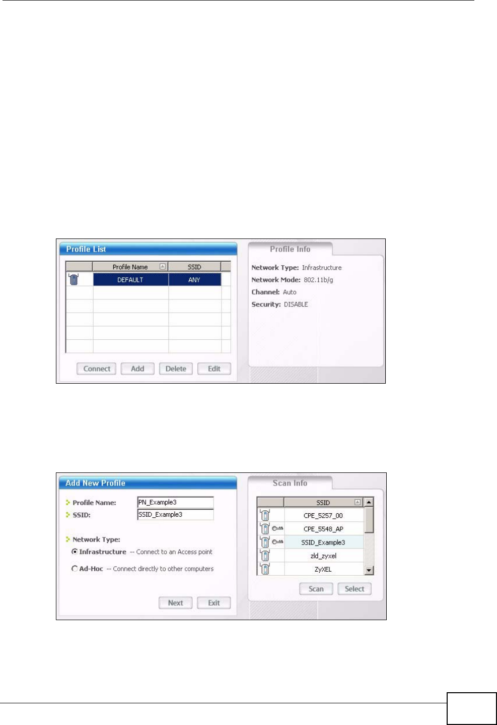
Chapter 4 Tutorial
P-2612HWU-F1 User’s Guide 65
4.2.3.2 Creating and Using a Profile
A profile lets you easily connect to the same wireless network again later. You can
also configure different profiles for different networks, for example if you connect
a notebook computer to wireless networks at home and at work.
This example illustrates how to set up a profile and connect the wireless client to
an AP configured for WPA-PSK security. In this example, the SSID is
“SSID_Example3”, the profile name is “PN_Example3” and the pre-shared key is
“ThisismyWPA-PSKpre-sharedkey”. You have chosen the profile name
“PN_Example3”.
1Open the ZyXEL utility and click the Profile tab to open the screen shown next.
Click Add to configure a new profile.
Figure 35 ZyXEL Utility: Profile
2The Add New Profile screen appears. The wireless client automatically searches
for available wireless networks, and displays them in the Scan Info box. Click
Scan if you want to search again. You can also configure your profile for a wireless
network that is not in the list.
Figure 36 ZyXEL Utility: Add New Profile
3Give the profile a descriptive name (of up to 32 printable ASCII characters). Select
Infrastructure and either manually enter or select the AP's SSID in the Scan
Info table and click Select.
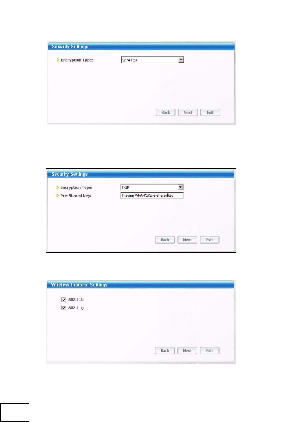
Chapter 4 Tutorial
P-2612HWU-F1 User’s Guide
66
4Choose the same encryption method as the AP to which you want to connect (In
this example, WPA-PSK).
Figure 37 ZyXEL Utility: Profile Security
5This screen varies depending on the encryption method you selected in the
previous screen. Enter the pre-shared key and leave the encryption type at the
default setting.
Figure 38 ZyXEL Utility: Profile Encryption
6In the next screen, leave both boxes selected.
Figure 39 Profile: Wireless Protocol Settings.
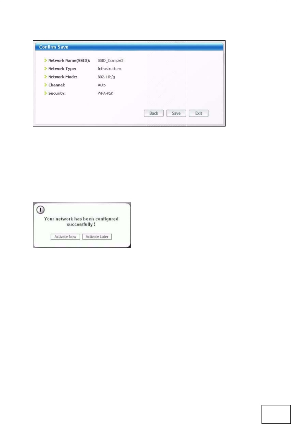
Chapter 4 Tutorial
P-2612HWU-F1 User’s Guide 67
7Verify the profile settings in the read-only screen. Click Save to save and go to the
next screen.
Figure 40 Profile: Confirm Save
8Click Activate Now to use the new profile immediately. Otherwise, click the
Activate Later button.
If you clicked Activate Later, you can select the profile from the list in the Profile
screen and click Connect to activate it.
Note: Only one profile can be activated and used at any given time.
Figure 41 Profile: Activate
9When you activate the new profile, the ZyXEL utility returns to the Link Info
screen while it connects to the AP using your settings. When the wireless link is
established, the ZyXEL utility icon in the system tray turns green and the Link
Info screen displays details of the active connection.
10 Open your Internet browser, enter http://www.zyxel.com or the URL of any other
web site in the address bar and press ENTER. If you are able to access the web
site, your new profile is successfully configured.
11 If you cannot access the Internet go back to the Profile screen, select the profile
you are using and click Edit. Check the details you entered previously. Also, refer
to the Troubleshooting section of this User's Guide or contact your network
administrator if necessary.
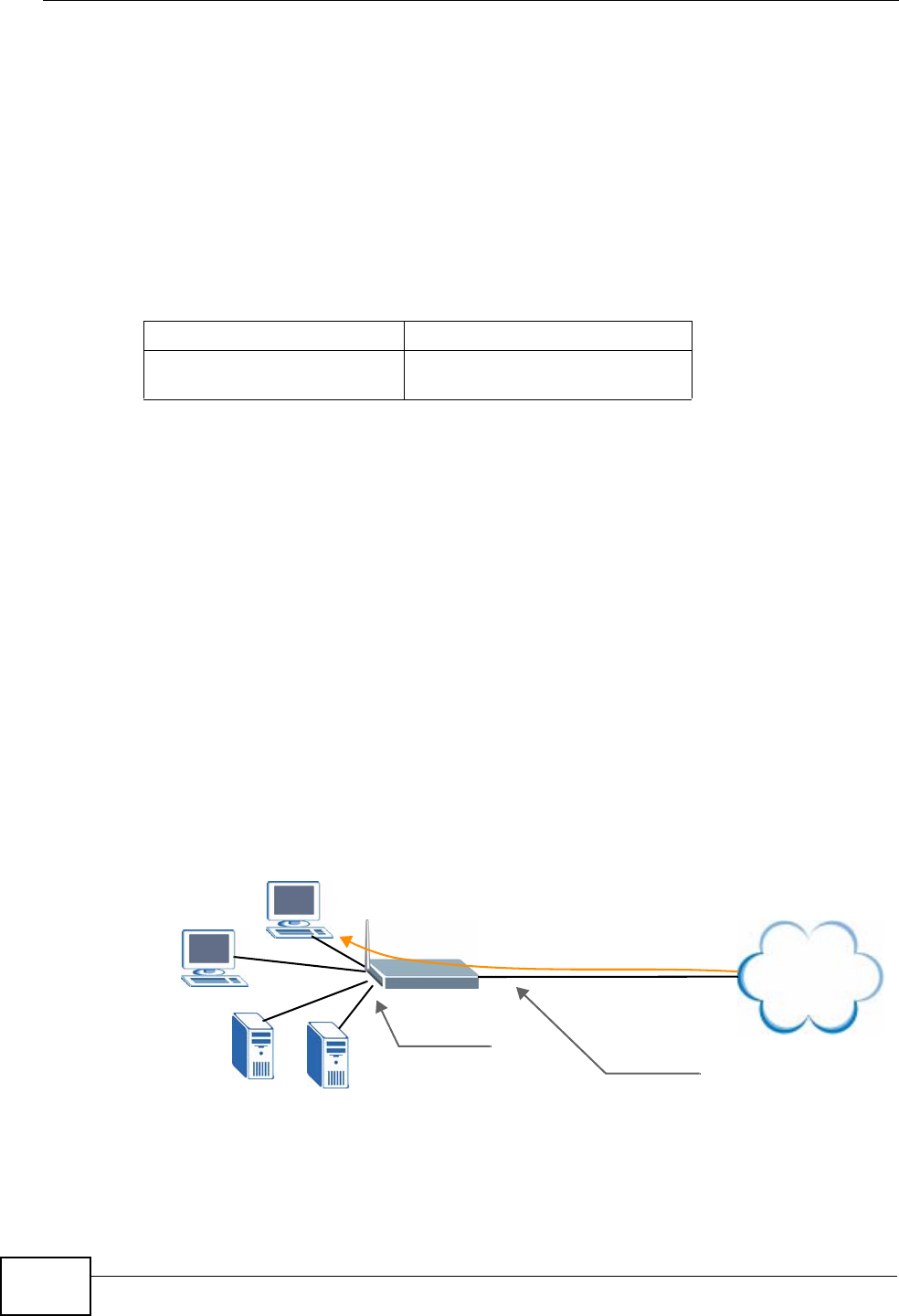
Chapter 4 Tutorial
P-2612HWU-F1 User’s Guide
68
4.3 Using NAT with Multiple Public IP Addresses
This chapter shows you examples of how to set up your ZyXEL Device if you have
more than one fixed (static) IP address from your ISP.
4.3.1 Example Parameters and Scenario
The following table shows the public IP addresses from your ISP and your ZyXEL
Device’s LAN IP address.
The following figure shows the network you want to set up in this example.
• Assign the first public address (1.2.3.4) to the ZyXEL Device’s WAN port.
• Map the second and third public IP addresses (1.2.3.5 and 1.2.3.6) to the web
and mail servers (192.168.1.12 and 192.168.1.13) respectively for traffic in
both directions.
• Map the first public address (1.2.3.4) to outgoing traffic from other local
computers.
• Map the first public address (1.2.3.4) to incoming traffic from the WAN.
• Forward FTP traffic using port 21 from the WAN to a specific local computer
(192.168.1.39).
• The last public IP address (1.2.3.7) is not mapped to any device and is reserved
for future use.
Figure 42 Tutorial Example: Using NAT with Static Public IP Addresses
To set up this network, we are going to:
Public IP Addresses 1.2.3.4 to 1.2.3.7
ZyXEL Device’s LAN IP
Address 192.168.1.1
Internet
FTP
FTP
192.168.1.39
192.168.1.39
192.168.1.12 192.168.1.13
Mail
Web
192.168.1.1
1.2.3.4
1.2.3.5
1.2.3.6
1.2.3.7
WAN
LAN Mapping rules:
192.168.1.12 <---> 1.2.3.5 (1-1)
192.168.1.13 <---> 1.2.3.6 (1-1)
Other outgoing LAN traffic ---> 1.2.3.4 (M-1)
Incoming traffic <--- 1.2.3.4 (Server)
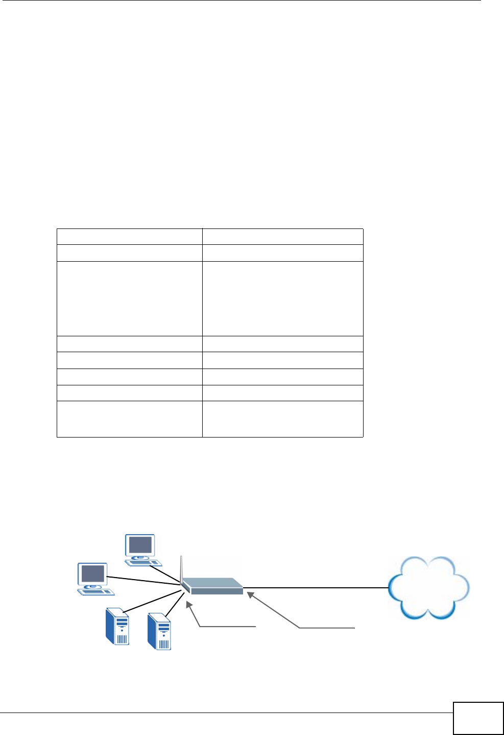
Chapter 4 Tutorial
P-2612HWU-F1 User’s Guide 69
1Configure the WAN connection to use the first public IP address (1.2.3.4).
2Configure NAT address mapping for other public IP addresses (1.2.3.5 and
1.2.3.6).
3Configure NAT port forwarding to forward FTP traffic from the WAN to a specific
computer on your local network.
4.3.2 Configuring the WAN Connection with a Static IP
Address
The following table shows the information your ISP gave you for Internet
connection.
Follow the steps below to configure your ZyXEL Device for Internet access using
PPPoE in this example.
Figure 43 Tutorial Example: WAN Connection with a Static Public IP Address
Encapsulation PPPoE
VPI/VCI 8/33
Public IP Addresses 1.2.3.4
1.2.3.5
1.2.3.6
1.2.3.7
Gateway IP Address 1.2.3.89
Subnet Mask 255.255.255.0
User Name exampleuser
Password abcd1234
DNS Server 1.2.1.1
1.2.1.2
Internet
192.168.1.1 1.2.3.4
WAN
LAN

Chapter 4 Tutorial
P-2612HWU-F1 User’s Guide
70
1Click Network > WAN.
2Make sure the DSL/WAN switch (on the back of the ZyXEL Device) is pushed to
the DSL side and the WAN mode is ADSL WAN.
3Select Routing in the Mode field and select PPPoE from the Encapsulation
drop-down list box.
4Enter the information (such as the user name, password and VPI/VCI value)
provided by your ISP. If your ISP didn’t give you the service name, leave the field
blank.
5In the IP Address section, select Static IP Address and enter the first fixed
public IP address (“1.2.3.4” in this example).
6Configure the IP address of the DNS server the ZyXEL Device can query to resolve
domain names. Select UserDefined and enter the first and second DNS server’s
IP addresses given by your ISP.
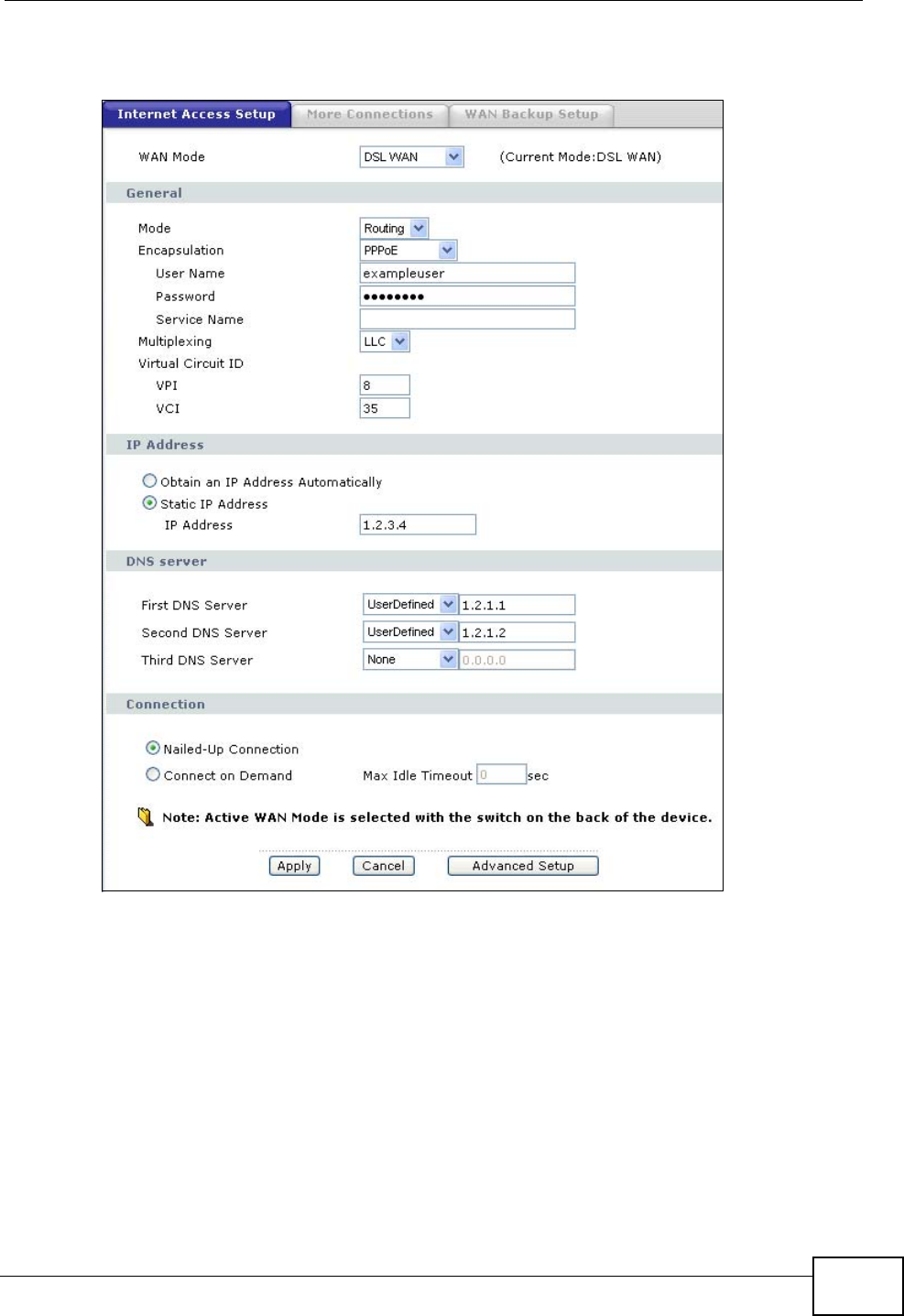
Chapter 4 Tutorial
P-2612HWU-F1 User’s Guide 71
7Click Apply to save your changes.
Figure 44 Tutorial Example: WAN Screen
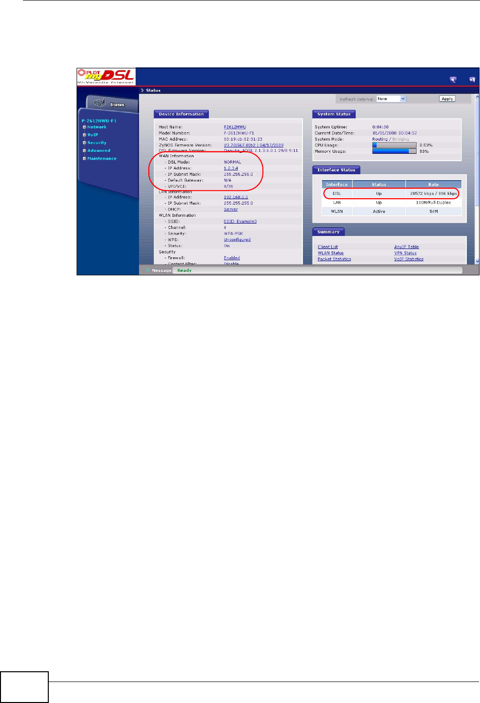
Chapter 4 Tutorial
P-2612HWU-F1 User’s Guide
72
8Go to the Status screen to check your WAN connection status. Make sure the
status is not down.
Figure 45 Tutorial Example: Status
4.3.3 Public IP Address Mapping
To have the local computers and servers use specific WAN IP addresses, you need
to map static public IP addresses to them.
Note: The one-to-one NAT address mapping rules are for both incoming and outgoing
connections. The ZyXEL Device forwards traffic that is initiated from either the
LAN or the WAN to the destination IP address.
Note: The many-to-one or many-to-many NAT address mapping rules are for
outgoing connections only. That means only traffic initiated from the LAN or
returned packets are allowed to go through the ZyXEL Device.
In this example, you create two one-to-one rules to map the internal web server
(192.168.1.12) and mail server (192.168.1.13) to different static public IP
addresses. The many-to-one rule maps a public IP address (1.2.3.4, that is, the
ZyXEL Device’s WAN IP address) to outgoing LAN traffic. It allows other local
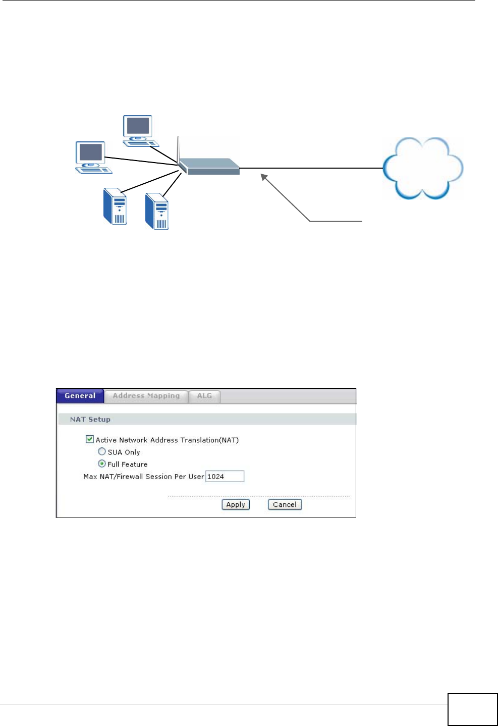
Chapter 4 Tutorial
P-2612HWU-F1 User’s Guide 73
computers on the same subnet as the ZyXEL Device’s LAN IP address to use this
IP address to access the Internet.
Figure 46 Tutorial Example: Mapping Multiple Public IP Addresses to Inside Servers
Note: The ZyXEL Device applies the rules in the order that you specify. You should
put any one-to-one rules before a many-to-one rule.
1Click Network > NAT > General.
2Enable NAT and select Full Feature as you have multiple public IP addresses to
map to private IP addresses. Click Apply.
Figure 47 Tutorial Example: NAT > NAT Overview
3Click the Address Mapping tab.
Internet
192.168.1.39
192.168.1.39
192.168.1.12 192.168.1.13
Mail
Web
1.2.3.4
1.2.3.5
1.2.3.6
1.2.3.7
WAN
LAN Mapping rules:
192.168.1.12 <---> 1.2.3.5 (1-1)
192.168.1.13 <---> 1.2.3.6 (1-1)
Other outgoing LAN traffic ---> 1.2.3.4 (M-1)
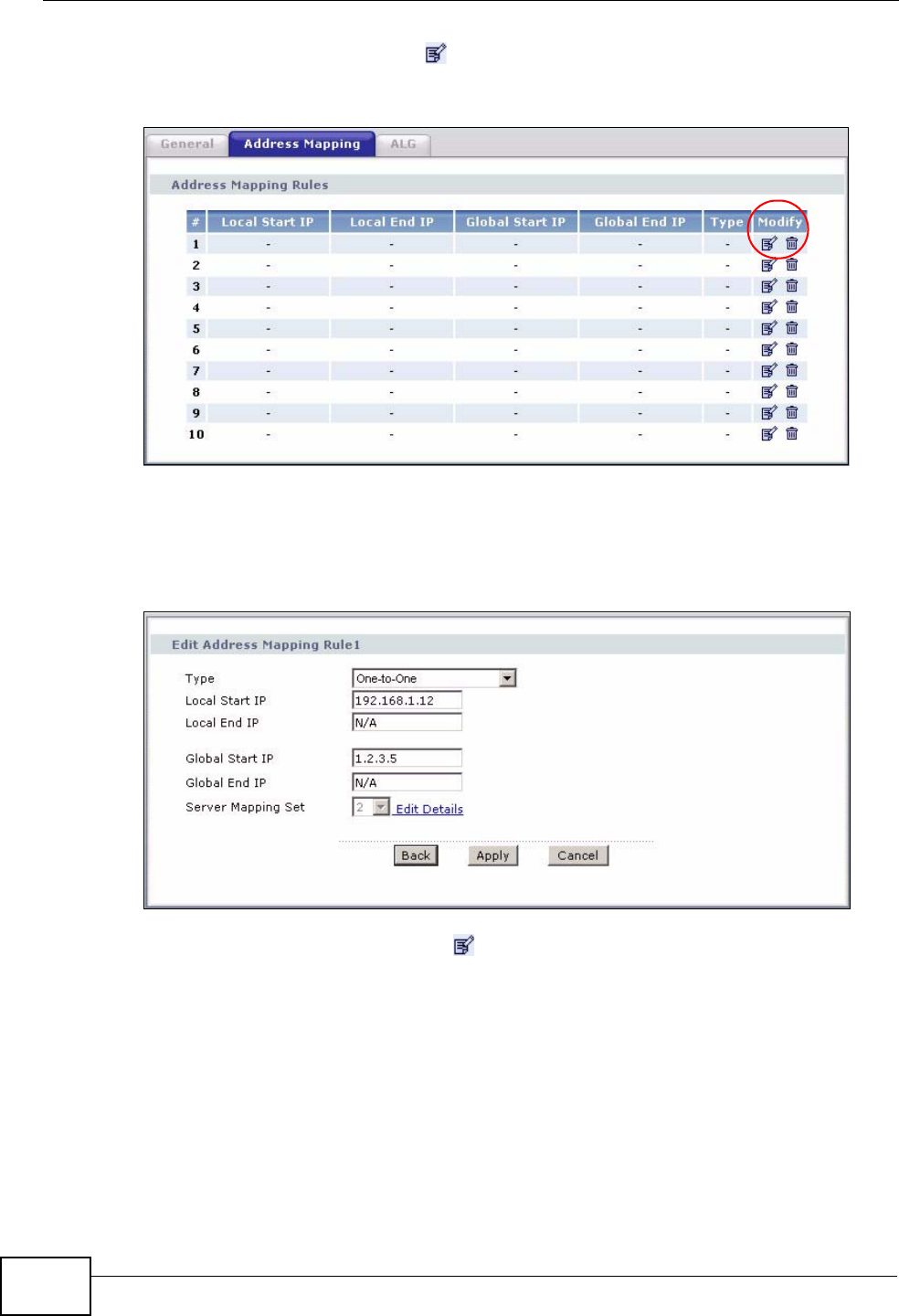
Chapter 4 Tutorial
P-2612HWU-F1 User’s Guide
74
4Click the first rule’s Edit icon ( ) in the Modify column to display the Edit
Address Mapping Rule screen.
Figure 48 Tutorial Example: NAT > Address Mapping
5Map a public IP address to the web server.
Select the One-to-One type and enter 192.168.1.12 as the local start IP address
and 1.2.3.5 as the global start IP address. Click Apply.
Figure 49 Tutorial Example: NAT Address Mapping Edit: One-to-One (1)
6Click the second rule’s Edit icon ( ).
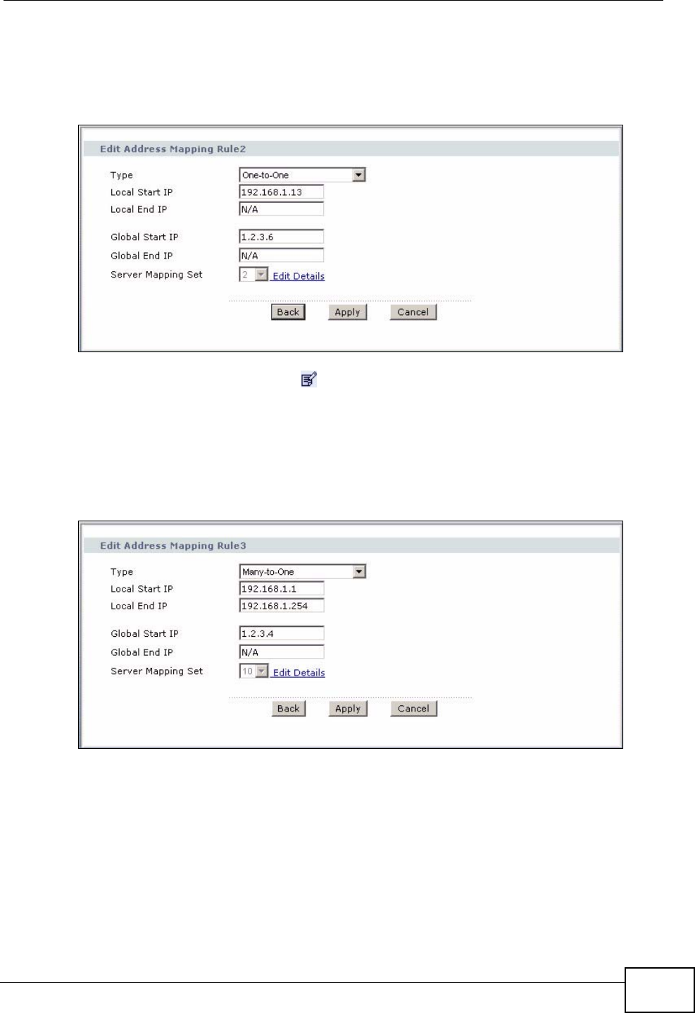
Chapter 4 Tutorial
P-2612HWU-F1 User’s Guide 75
7Map a public IP address to the mail server.
Select the One-to-One type and enter 192.168.1.13 as the local start IP address
and 1.2.3.6 as the global start IP address. Click Apply.
Figure 50 Tutorial Example: NAT Address Mapping Edit: One-to-One (2)
8Click the third rule’s Edit icon ( ).
9Map a public IP address to other outgoing LAN traffic.
Select the Many-to-One type and enter 192.168.1.1 as the local start IP address,
192.168.1.254 as the local end IP address and 1.2.3.4 as the global start IP
address. Click Apply.
Figure 51 Tutorial Example: NAT Address Mapping Edit: Many-to-One
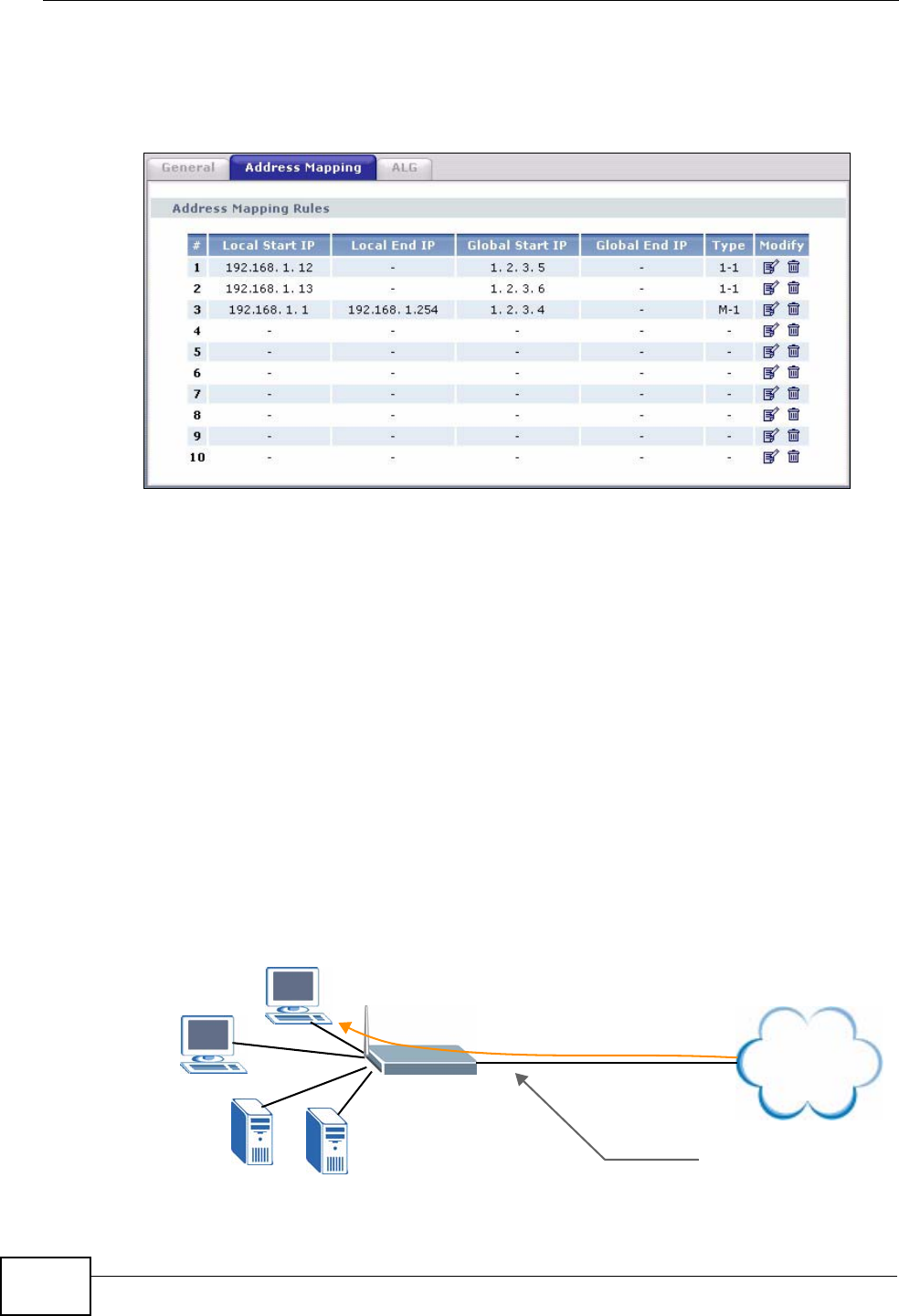
Chapter 4 Tutorial
P-2612HWU-F1 User’s Guide
76
10 After the configurations, the Address Mapping screen looks as shown. You still
have one IP address (1.2.3.7) that can be assigned to another internal server
when you expand your network.
Figure 52 Tutorial Example: NAT Address Mapping Done
Note: To allow traffic from the WAN to be forwarded through the ZyXEL Device, you
must also create a firewall rule. Refer to Section 4.3.5 on page 77 for more
information.
4.3.4 Forwarding Traffic from the WAN to a Local Computer
A server NAT address mapping rule allows computers behind the NAT be
accessible to the outside world. To have the ZyXEL Device forward incoming traffic
to a specific computer on your local network, you should also create a port
forwarding (server mapping) rule.
In this example, you want to forward FTP traffic using port 21 to the computer
with the IP address of 192.168.1.39.
Figure 53 Tutorial Example: Forwarding Incoming FTP Traffic to a Local Computer
Internet
FTP
FTP
192.168.1.39
192.168.1.39
192.168.1.12 192.168.1.13
Mail
Web
1.2.3.4
1.2.3.5
1.2.3.6
1.2.3.7
WAN
LAN Mapping rules:
Incoming traffic <--- 1.2.3.4 (Server)
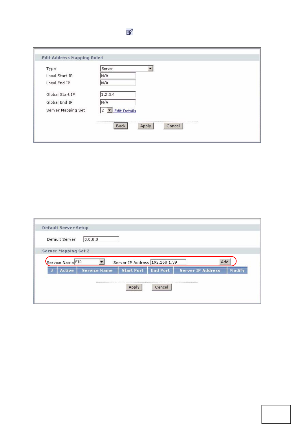
Chapter 4 Tutorial
P-2612HWU-F1 User’s Guide 77
1Click Network > NAT > Address Mapping.
2Click the forth rule’s Edit icon ( ) to configure a server rule.
Figure 54 Tutorial Example: NAT Address Mapping Edit: Server
3Select a number and click the Edit Details link to edit a port forwarding set.
4Select FTP from the Service Name drop-down list box, and enter “192.168.1.39”
as the server IP address. Click Add to add the rule to the table.
5Click Apply to go back to the Edit Address Mapping Rule screen. Click Apply
again.
Figure 55 Tutorial Example: NAT Port Forwarding
4.3.5 Allow WAN-to-LAN Traffic through the Firewall
By default, the ZyXEL Device blocks any traffic initiated from the WAN to the LAN.
To have the ZyXEL Device forward traffic initiated from the WAN to a local
computer or server on the LAN, you need to configure a firewall rule to allow it.
In this example, you create the firewall rules to allow traffic from the WAN to the
following servers on the LAN:
• Web server
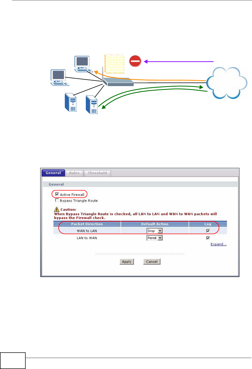
Chapter 4 Tutorial
P-2612HWU-F1 User’s Guide
78
• Mail server
•FTP server
Figure 56 Tutorial Example: Allow WAN-to-LAN Traffic
1Click Security > Firewall.
2Make sure the firewall is enabled and traffic from the WAN to the LAN is dropped.
Figure 57 Tutorial Example: Firewall > General
3Go to the Rules screen.
Internet
FTP
FTP
192.168.1.39
192.168.1.39
192.168.1.12 192.168.1.13
Mail
Web
WAN
LAN
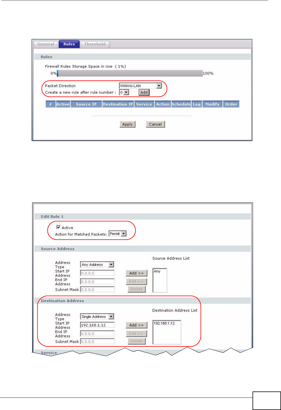
Chapter 4 Tutorial
P-2612HWU-F1 User’s Guide 79
4Select the WAN to LAN packet direction and click the Add button to create a new
firewall rule.
Figure 58 Tutorial Example: Firewall Rules: WAN to LAN
5Configure a firewall rule to allow traffic from the WAN to the web server.
Select Any in the Destination Address List box and click Delete.
Select Single Address as the destination address type. Enter “192.168.1.12” and
click Add >>.
Figure 59 Tutorial Example: Firewall Rule: WAN to LAN Address Edit for Web
Server
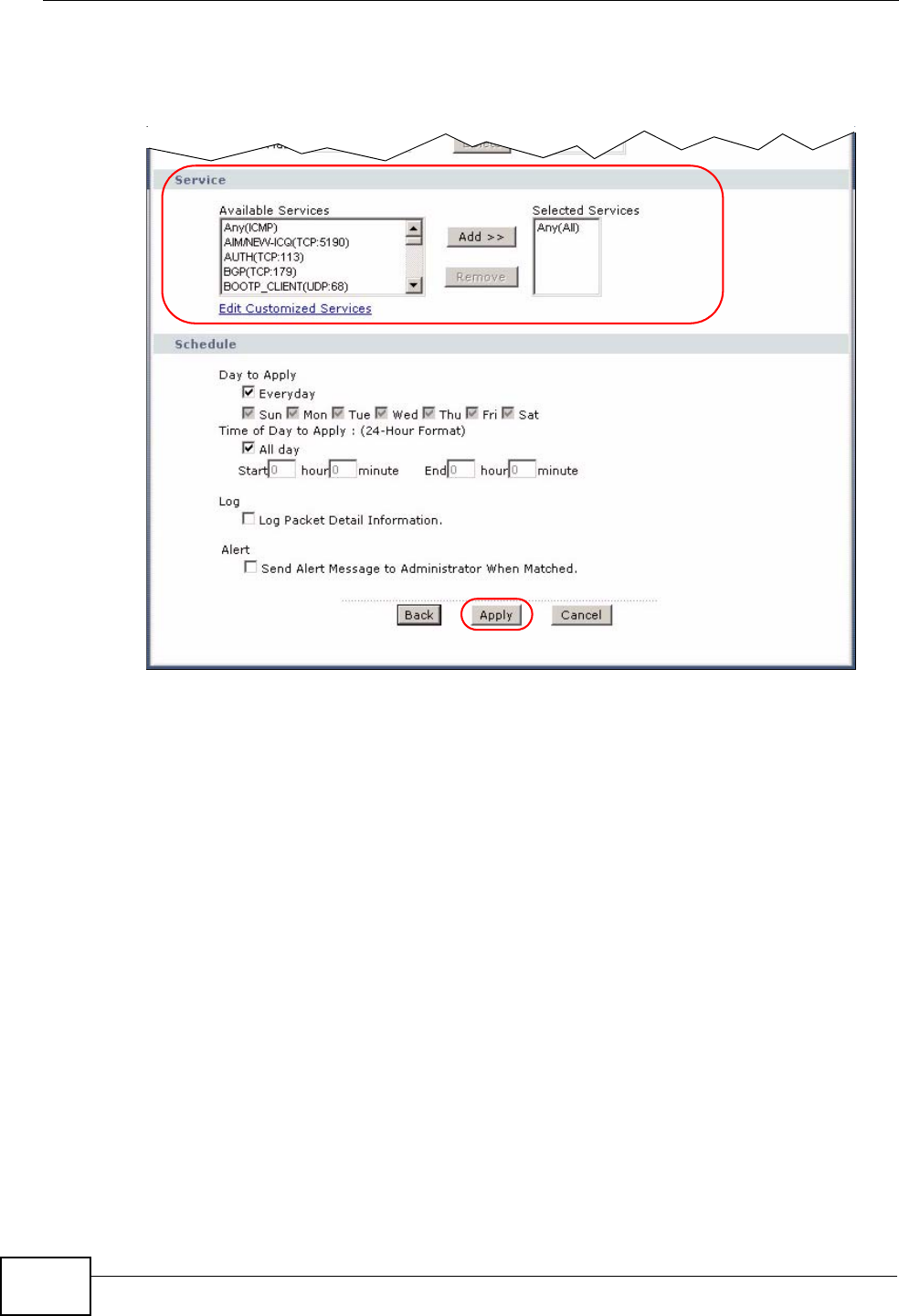
Chapter 4 Tutorial
P-2612HWU-F1 User’s Guide
80
6Select Any(All) in the Available Services box on the left, and click Add >> to
add it to the Selected Services box on the right. Click Apply.
Figure 60 Tutorial Example: Firewall Rule: WAN to LAN Service Edit for Web Server
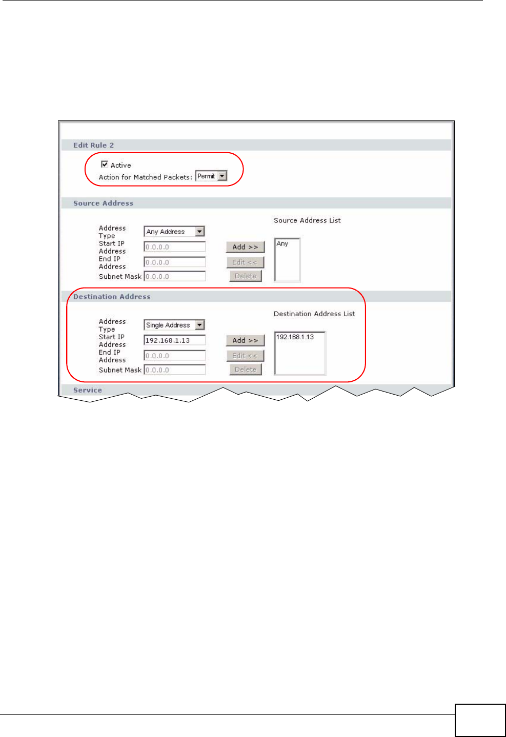
Chapter 4 Tutorial
P-2612HWU-F1 User’s Guide 81
7Click the Add button to configure a firewall rule to allow traffic from the WAN to
the mail server.
Select Any in the Destination Address List box and click Delete.
Select Single Address as the destination address type. Enter “192.168.1.13” and
click Add.
Figure 61 Tutorial Example: Firewall Rule: WAN to LAN Address Edit for Mail Server
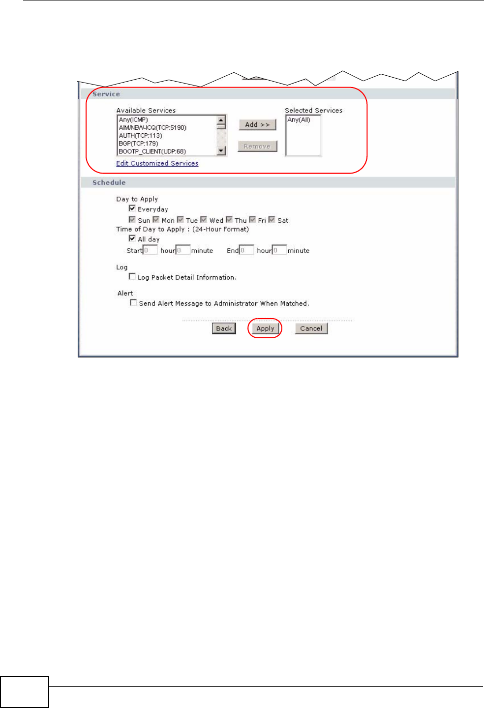
Chapter 4 Tutorial
P-2612HWU-F1 User’s Guide
82
8Select Any(All) in the Available Services box on the left, and click Add >> to
add it to the Selected Services box on the right. Click Apply.
Figure 62 Tutorial Example: Firewall Rule: WAN to LAN Service Edit for Mail Server
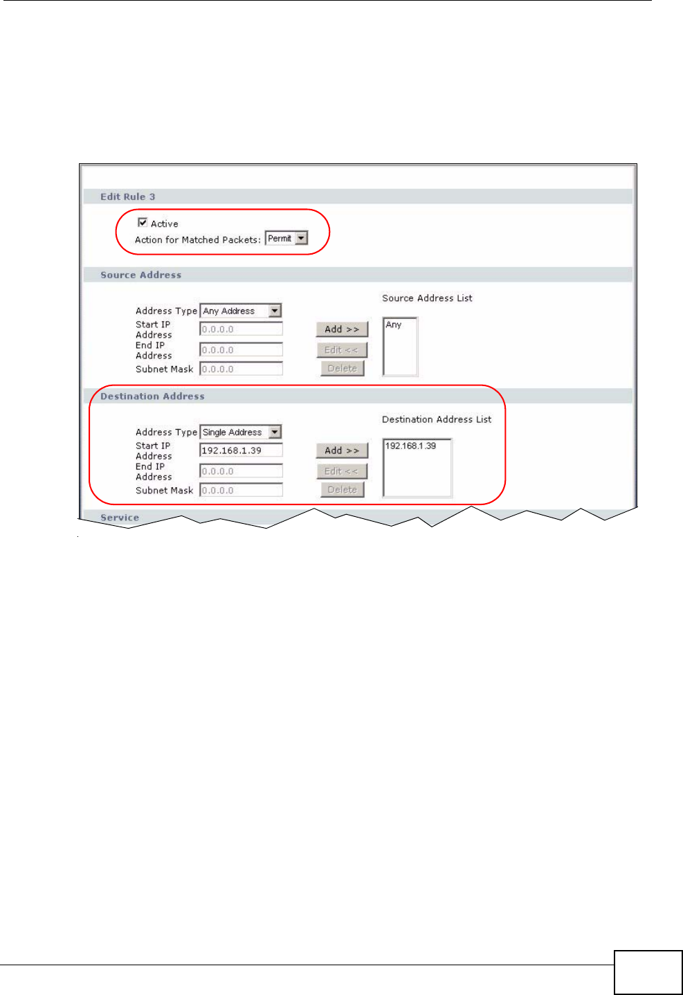
Chapter 4 Tutorial
P-2612HWU-F1 User’s Guide 83
9Click the Add button to configure a firewall rule to allow FTP traffic from the WAN
to the FTP server.
Select Any in the Destination Address List box and click Delete.
Select Single Address as the destination address type. Enter “192.168.1.39” and
click Add.
Figure 63 Tutorial Example: Firewall Rule: WAN to LAN Address Edit for FTP Server
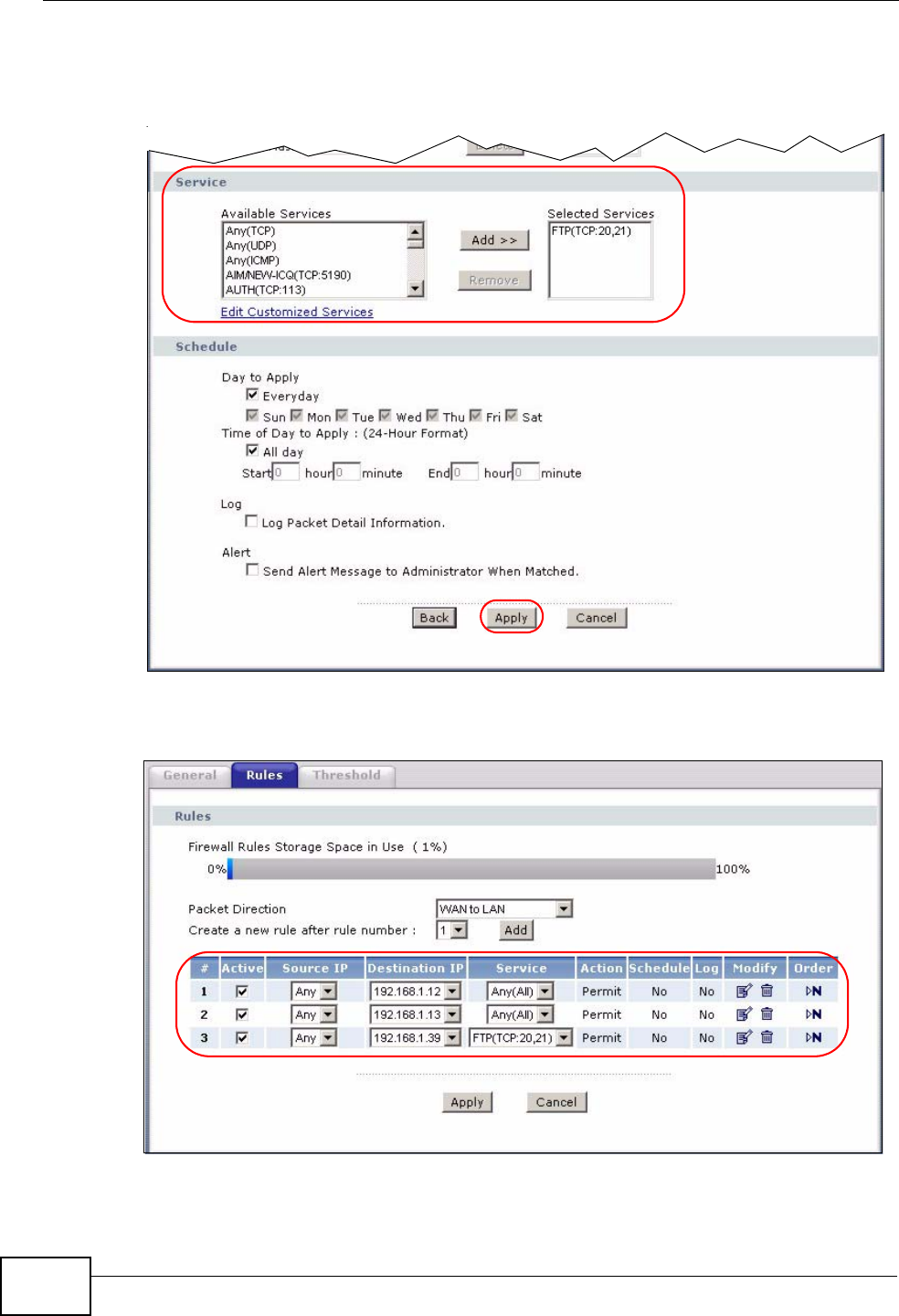
Chapter 4 Tutorial
P-2612HWU-F1 User’s Guide
84
10 Select FTP(TCP:20,21) in the Available Services box on the left, and click Add
>> to add it to the Selected Services box on the right. Click Apply.
Figure 64 Tutorial Example: Firewall Rule: WAN to LAN Service Edit for FTP Server
11 When you are done, the Rules screen looks as shown.
Figure 65 Tutorial Example: Firewall Rules Done

Chapter 4 Tutorial
P-2612HWU-F1 User’s Guide 85
4.3.6 Testing the Connections
1Open the web browser on one of the local computers and enter any web site’s URL
in the address bar. If you can access the web site, your WAN connection and NAT
address mapping are configured successfully. If you cannot access it, make sure
you entered the correct information in the WAN and NAT Address Mapping
screens. Also check that the Internet account is active and the computer’s IP
address is in the same subnet as the ZyXEL Device.
2Open your web browser and try accessing the web server (1.2.3.5) from the
outside network. If you cannot access the web server, make sure the NAT address
mapping rule is configured correctly and there is a firewall rule to allow HTTP
traffic from the WAN to the web server.
3Try accessing the FTP server (1.2.3.4) from the outside network to send or
retrieve a file. If you cannot access the FTP server, make sure the NAT port
forwarding rule is active and there is a firewall rule to allow FTP traffic from the
WAN to FTP server.
4.4 Using NAT with Multiple Game Players
If two users (behind the ZyXEL Device) want to connect to the same server to play
online games at the same time, but the server does not allow more than one login
from the same IP address, you can configure a many-to-many rule instead of a
many-to-one rule.
In this example, you have four static IP addresses (1.2.3.4 to 1.2.3.7) from your
ISP. After you set up your WAN connection (see Section 4.3.2 on page 69), use
the NAT > Address Mapping screen to map the third and forth public IP
addresses to the mail server (192.168.1.12) and web server (192.168.1.13)
respectively. The first and second public IP addresses are mapped to other
outgoing LAN traffic. See Section 4.3.3 on page 72 for more information about IP
address mapping.
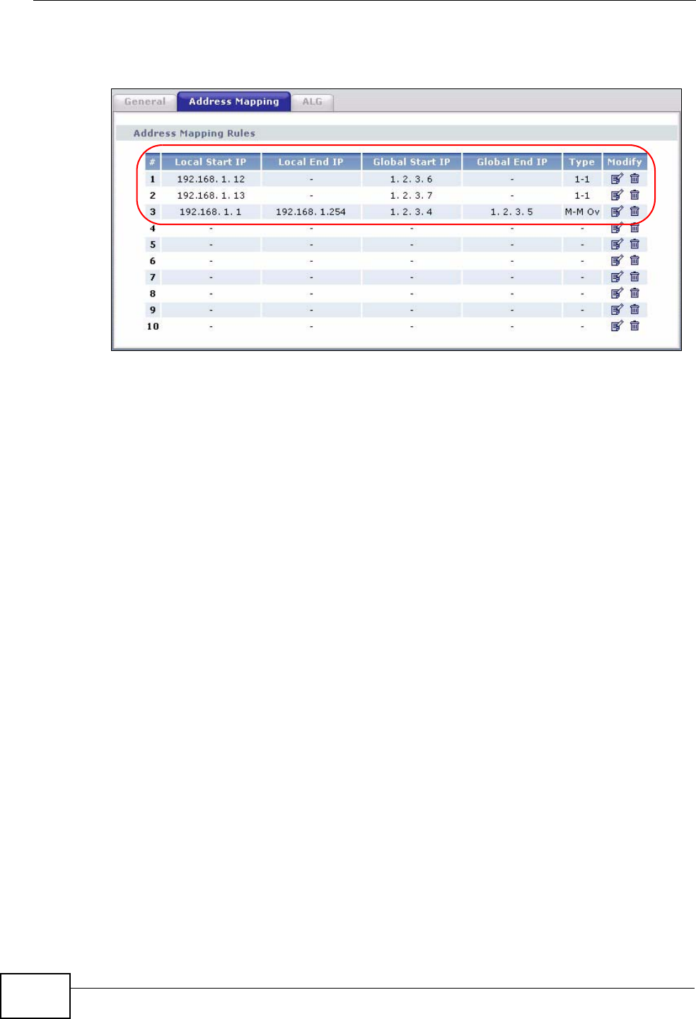
Chapter 4 Tutorial
P-2612HWU-F1 User’s Guide
86
When you finish configuration, the screen looks as shown.
Figure 66 Tutorial Example: NAT Address Mapping Done: Game Playing
Note: To allow traffic from the WAN to be forwarded through the ZyXEL Device, you
must also create a firewall rule. Refer to Section 4.3.5 on page 77 for more
information.
4.5 How to Make a VoIP Call
You can register a SIP account with the SIP server and make voice calls over the
Internet to another VoIP device.
4.5.1 VoIP Calls With a Registered SIP Account
To use a registered SIP account, you should have applied for a SIP account with
the VoIP service provider.
4.5.1.1 SIP Account Registration
Follow the steps below to register and activate your SIP account.
1Make sure your ZyXEL Device is connected to the Internet.
2Open the web configurator.
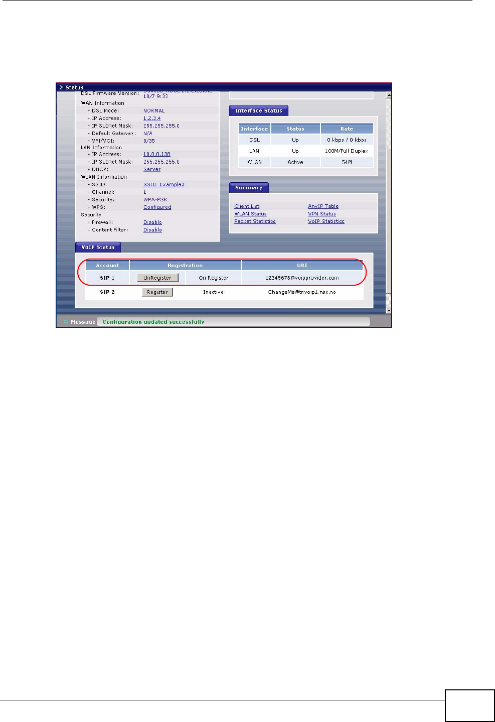
Chapter 4 Tutorial
P-2612HWU-F1 User’s Guide 87
3Go to the Status screen to check if your SIP account has been registered
successfully. If registration failed, check your Internet connection and click
Register to register your SIP account again.
Figure 67 Tutorial Example: Status
4.5.1.2 Analog Phone Configuration
1Click VoIP > Phone to open the Analog Phone screen.
2Select Phone1 to configure the first phone port.
3Select SIP1 from the SIP Account drop-down list box in the Outgoing Call Use
section to have the phone (connected to the first phone port) use the registered
SIP1 account to make outgoing calls.
4Select the SIP1 check box in the Incoming Call apply to section to have the
phone (connected to the first phone port) receive phone calls for the SIP1
account.
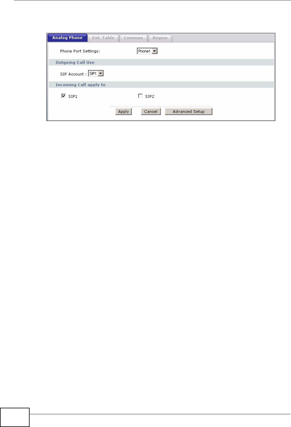
Chapter 4 Tutorial
P-2612HWU-F1 User’s Guide
88
5Click Apply to save your changes.
Figure 68 Tutorial Example: Analog Phone
4.5.1.3 Making a VoIP Call
1Make sure you connect a telephone to the first phone port on the ZyXEL Device.
2Make sure the ZyXEL Device is on and connected to the Internet.
3Pick up the phone receiver.
4Dial the VoIP phone number you want to call.

89
PART II
Advanced
Status Screens (91)
WAN Setup (101)
LAN Setup (117)
Wireless LAN (133)
Network Address Translation (NAT) (165)
Voice (181)
Phone Usage (217)
Firewall (225)
Content Filtering (247)
VPN (253)
Certificates (287)
Static Route (313)
802.1Q/1P (317)
Quality of Service (QoS) (329)
Dynamic DNS Setup (345)
Remote Management Configuration (349)
Universal Plug-and-Play (UPnP) (361)
File Sharing (375)
Sharing a USB Printer (389)

90
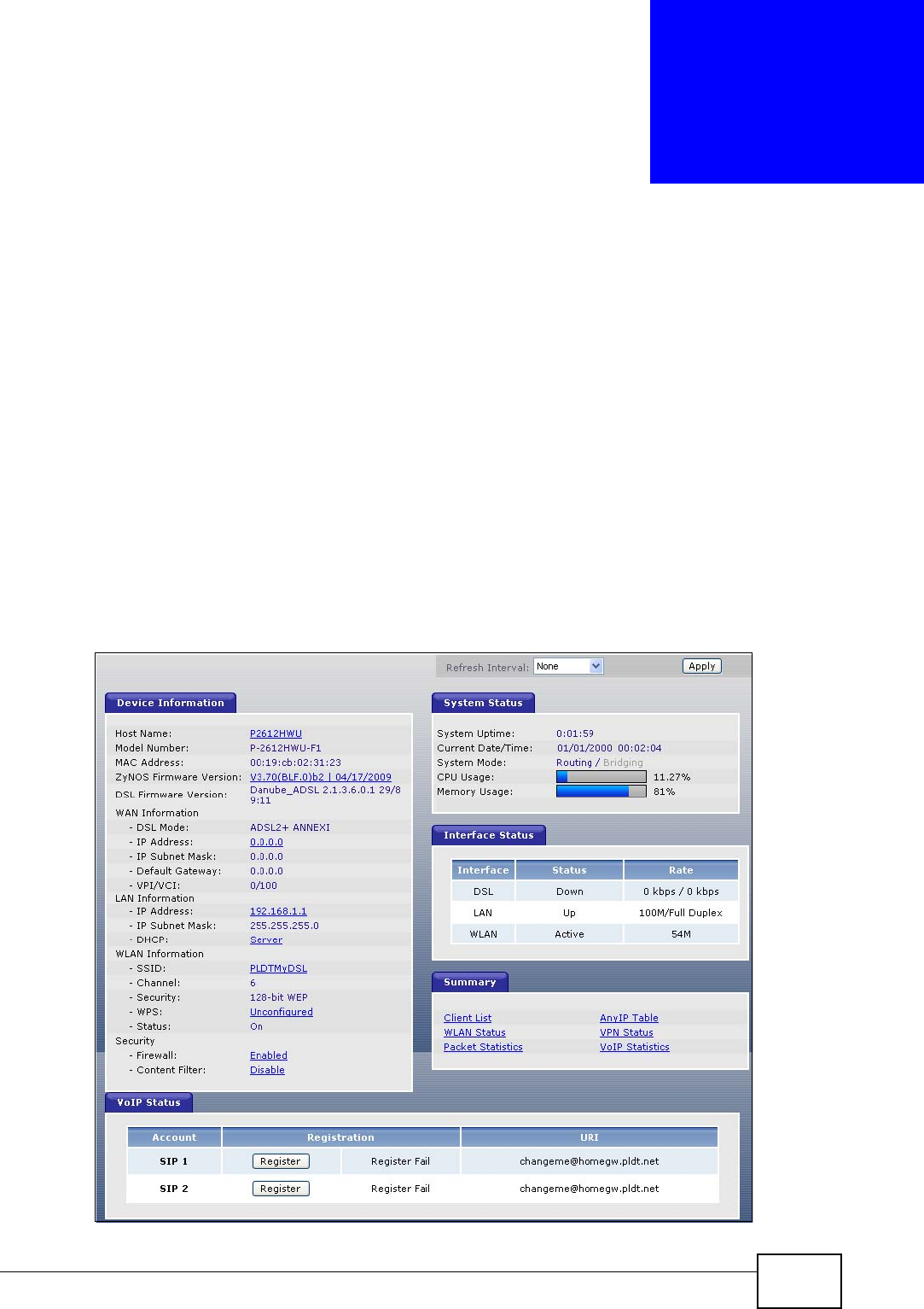
P-2612HWU-F1 User’s Guide 91
CHAPTER 5
Status Screens
Use the Status screens to look at the current status of the device, system
resources, interfaces (LAN, WAN and WLAN), and SIP accounts. You can also
register and unregister SIP accounts. The Status screen also provides detailed
information from Any IP and DHCP and statistics from VoIP, and traffic.
5.1 Status Screen
Click Status to open this screen. The screen varies slightly depending on the WAN
mode you set using the DSL/WAN switch.
Figure 69 Status Screen (ADSL WAN mode)
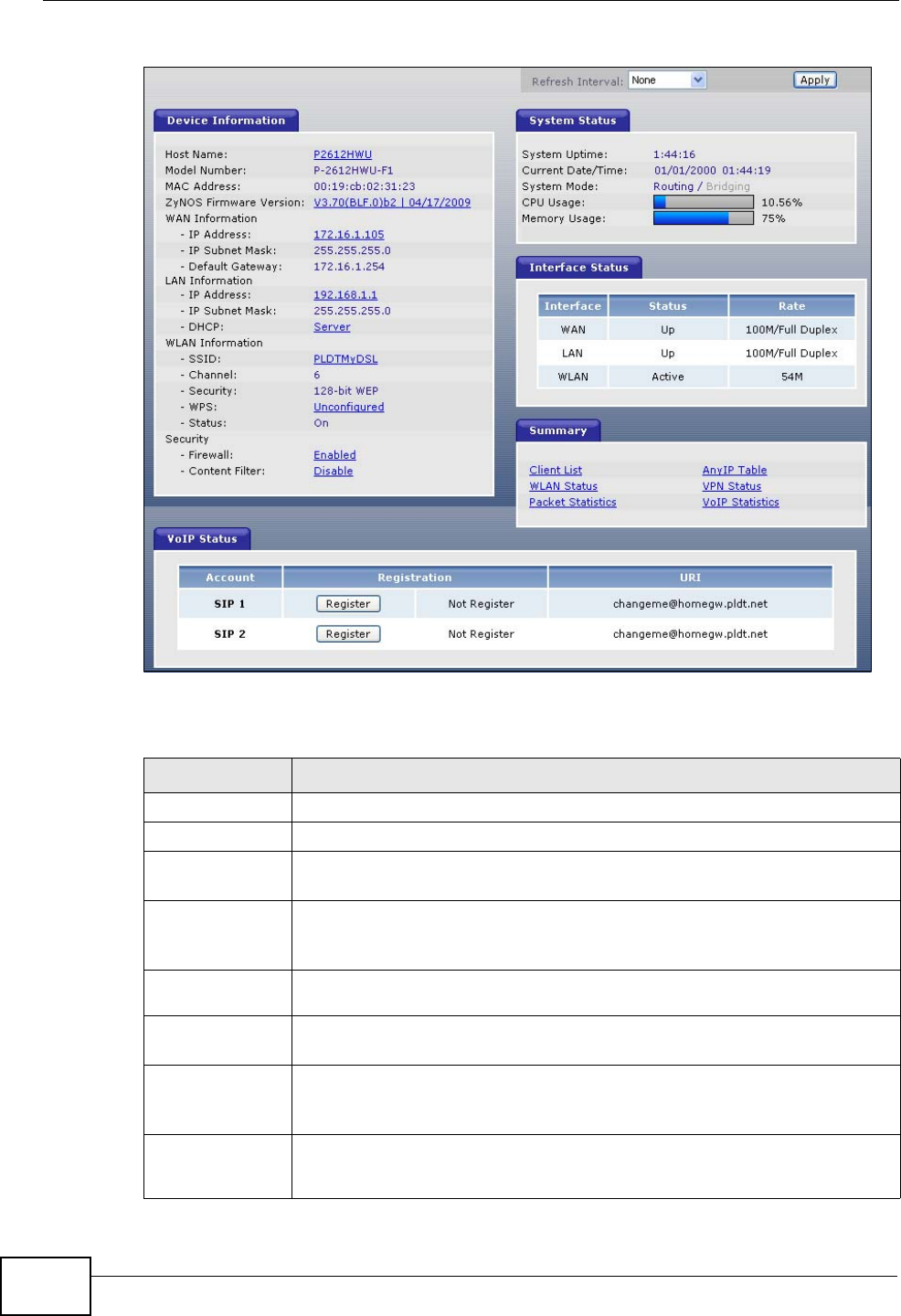
Chapter 5 Status Screens
P-2612HWU-F1 User’s Guide
92
Figure 70 Status Screen (Ethernet WAN mode)
Each field is described in the following table.
Table 14 Status Screen
LABEL DESCRIPTION
Refresh Interval Enter how often you want the ZyXEL Device to update this screen.
Apply Click this to update this screen immediately.
Device
Information
Host Name This field displays the ZyXEL Device system name. It is used for
identification. You can change this in the Maintenance > System >
General screen’s System Name field.
Model
Number This is the model name of your device.
MAC
Address This is the MAC (Media Access Control) or Ethernet address unique to
your ZyXEL Device.
ZyNOS
Firmware
Version
This field displays the current version of the firmware inside the device.
It also shows the date the firmware version was created. Click this to go
to the screen where you can change it.
DSL
Firmware
Version
This field is not available when the WAN mode is Ethernet WAN.
This field displays the current version of the device’s DSL modem code.

Chapter 5 Status Screens
P-2612HWU-F1 User’s Guide 93
WAN
Information
DSL Mode This field is not available when the WAN mode is Ethernet WAN.
This is the DSL standard that your ZyXEL Device is using.
IP Address This field displays the current IP address of the ZyXEL Device in the
WAN. Click this to go to the screen where you can change it.
IP Subnet
Mask This field displays the current subnet mask in the WAN.
Default
Gateway This is the IP address of the default gateway, if applicable.
VPI/VCI This field is not available when the WAN mode is Ethernet WAN.
This is the Virtual Path Identifier and Virtual Channel Identifier that you
entered in the wizard or WAN screen.
LAN
Information
IP Address This field displays the current IP address of the ZyXEL Device in the
LAN. Click this to go to the screen where you can change it.
IP Subnet
Mask This field displays the current subnet mask in the LAN.
DHCP This field displays what DHCP services the ZyXEL Device is providing to
the LAN. Choices are:
Server - The ZyXEL Device is a DHCP server in the LAN. It assigns IP
addresses to other computers in the LAN.
Relay - The ZyXEL Device acts as a surrogate DHCP server and relays
DHCP requests and responses between the remote server and the
clients.
None - The ZyXEL Device is not providing any DHCP services to the
LAN.
Click this to go to the screen where you can change it.
WLAN
Information
SSID This is the descriptive name used to identify the ZyXEL Device in the
wireless LAN. Click this to go to the screen where you can change it.
Channel This is the channel number used by the ZyXEL Device now.
Security This displays the type of security mode the ZyXEL Device is using in the
wireless LAN.
WPS This displays the status of WPS (Wi-Fi Protected Setup). Click this to go
to the screen where you can change it.
Status This displays whether or not wireless LAN is enabled.
Security
Firewall This displays whether or not the ZyXEL Device’s firewall is activated.
Click this to go to the screen where you can change it.
Table 14 Status Screen
LABEL DESCRIPTION

Chapter 5 Status Screens
P-2612HWU-F1 User’s Guide
94
Content
Filter This displays whether or not the ZyXEL Device’s content filtering is
activated. Click this to go to the screen where you can change it.
System Status
System
Uptime This field displays how long the ZyXEL Device has been running since it
last started up. The ZyXEL Device starts up when you plug it in, when
you restart it (Maintenance > Tools > Restart), or when you reset it
(see Section 1.5 on page 30).
Current
Date/Time This field displays the current date and time in the ZyXEL Device. You
can change this in Maintenance > System > Time Setting.
System
Mode This displays whether the ZyXEL Device is functioning as a router or a
bridge.
CPU Usage This field displays what percentage of the ZyXEL Device’s processing
ability is currently used. When this percentage is close to 100%, the
ZyXEL Device is running at full load, and the throughput is not going to
improve anymore. If you want some applications to have more
throughput, you should turn off other applications.
Memory
Usage This field displays what percentage of the ZyXEL Device’s memory is
currently used. Usually, this percentage should not increase much. If
memory usage does get close to 100%, the ZyXEL Device is probably
becoming unstable, and you should restart the device. See Section 27.4
on page 452, or turn off the device (unplug the power) for a few
seconds.
Interface Status
Interface This column displays each interface the ZyXEL Device has.
Status This field indicates whether or not the ZyXEL Device is using the
interface.
For the DSL interface, this field displays Down (line is down), Up (line
is up or connected) if you're using Ethernet encapsulation and Down
(line is down), Up (line is up or connected), Idle (line (ppp) idle), Dial
(starting to trigger a call) and Drop (dropping a call) if you're using
PPPoE encapsulation.
For the WAN interface, this field displays Up when the ZyXEL Device is
using the interface and Down when the ZyXEL Device is not using the
interface.
For the LAN interface, this field displays Up when the ZyXEL Device is
using the interface and Down when the ZyXEL Device is not using the
interface.
For the WLAN interface, it displays Active when WLAN is enabled or
InActive when WLAN is disabled.
Rate For the LAN interface, this displays the port speed and duplex setting.
For the WAN interface, this displays the port speed and duplex setting.
For the DSL interface, it displays the downstream and upstream
transmission rate.
For the WLAN interface, it displays the maximum transmission rate
when WLAN is enabled or N/A when WLAN is disabled.
Table 14 Status Screen
LABEL DESCRIPTION

Chapter 5 Status Screens
P-2612HWU-F1 User’s Guide 95
Summary
Client List Click this link to view current DHCP client information. See Section 7.3
on page 122.
AnyIP Table Click this link to view a list of IP addresses and MAC addresses of
computers, which are not in the same subnet as the ZyXEL Device. See
Section 5.2 on page 96.
WLAN
Status Click this link to display the MAC address(es) of the wireless stations
that are currently associating with the ZyXEL Device. See Section 5.3
on page 96.
VPN Status Click this link to view the ZyXEL Device’s current VPN connections. See
Section 14.7 on page 271.
Packet
Statistics Click this link to view port status and packet specific statistics. See
Section 5.4 on page 97.
VoIP
Statistics Click this link to view statistics about your VoIP usage. See Section 5.5
on page 99.
VoIP Status
Account This column displays each SIP account in the ZyXEL Device.
Registration This field displays the current registration status of the SIP account. You
have to register SIP accounts with a SIP server to use VoIP.
If the SIP account is already registered with the SIP server,
• Click Unregister to delete the SIP account’s registration in the SIP
server. This does not cancel your SIP account, but it deletes the
mapping between your SIP identity and your IP address or domain
name.
• The second field displays Registered.
If the SIP account is not registered with the SIP server,
• Click Register to have the ZyXEL Device attempt to register the SIP
account with the SIP server.
• The second field displays the reason the account is not registered.
Inactive - The SIP account is not active. You can activate it in VoIP >
SIP > SIP Settings.
Register Fail - The last time the ZyXEL Device tried to register the SIP
account with the SIP server, the attempt failed. The ZyXEL Device
automatically tries to register the SIP account when you turn on the
ZyXEL Device or when you activate it.
URI This field displays the account number and service domain of the SIP
account. You can change these in VoIP > SIP > SIP Settings.
Table 14 Status Screen
LABEL DESCRIPTION
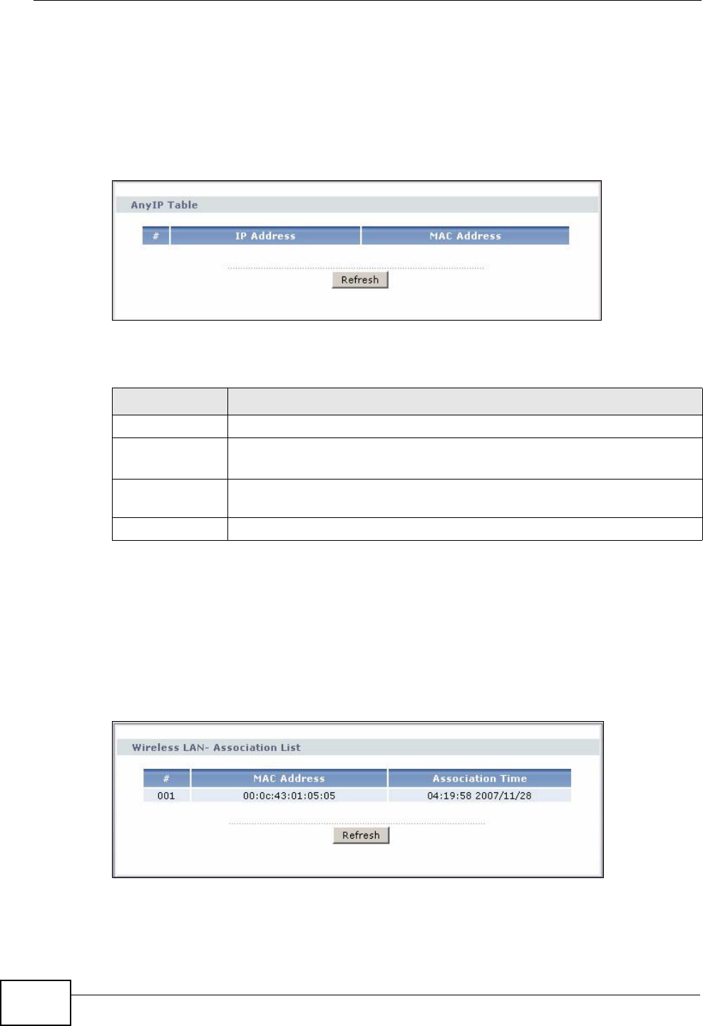
Chapter 5 Status Screens
P-2612HWU-F1 User’s Guide
96
5.2 Any IP Table
Click Status > AnyIP Table to access this screen. Use this screen to view the IP
address and MAC address of each computer that is using the ZyXEL Device but is
in a different subnet than the ZyXEL Device.
Figure 71 Any IP Table
Each field is described in the following table.
5.3 WLAN Status
Click Status > WLAN Status to access this screen. Use this screen to view the
wireless stations that are currently associated to the ZyXEL Device.
Figure 72 WLAN Status
Table 15 Any IP Table
LABEL DESCRIPTION
# This field is a sequential value. It is not associated with a specific entry.
IP Address This field displays the IP address of each computer that is using the ZyXEL Device
but is in a different subnet than the ZyXEL Device.
MAC Address This field displays the MAC address of the computer that is using the
ZyXEL Device but is in a different subnet than the ZyXEL Device.
Refresh Click this to update this screen.
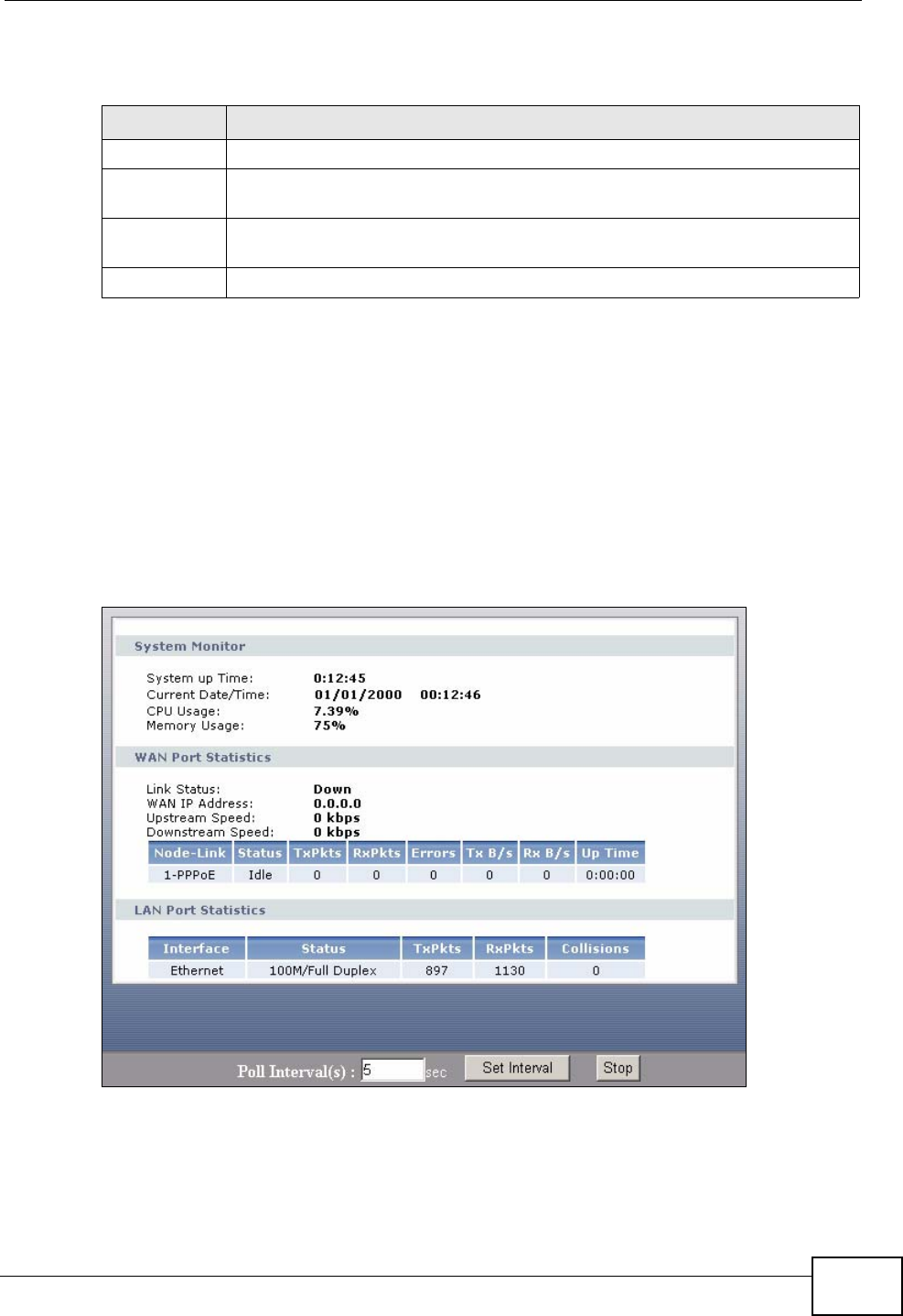
Chapter 5 Status Screens
P-2612HWU-F1 User’s Guide 97
The following table describes the labels in this screen.
5.4 Packet Statistics
Click Status > Packet Statistics to access this screen. Read-only information
here includes port status and packet specific statistics. Also provided are "system
up time" and "poll interval(s)". The Poll Interval(s) field is configurable. The
screen varies slightly depending on the WAN mode you set using the DSL/WAN
switch.
Figure 73 Packet Statistics
Table 16 WLAN Status
LABEL DESCRIPTION
# This is the index number of an associated wireless station.
MAC Address This field displays the MAC (Media Access Control) address of an
associated wireless station.
Association
TIme This field displays the time a wireless station first associated with the
ZyXEL Device.
Refresh Click Refresh to reload this screen.

Chapter 5 Status Screens
P-2612HWU-F1 User’s Guide
98
The following table describes the fields in this screen.
Table 17 Packet Statistics
LABEL DESCRIPTION
System Monitor
System up Time This is the elapsed time the system has been up.
Current Date/
Time This field displays your ZyXEL Device’s present date and time.
CPU Usage This field specifies the percentage of CPU utilization.
Memory Usage This field specifies the percentage of memory utilization.
WAN Port Statistics
Link Status This is the status of your WAN link.
WAN IP Address This is the IP address of the ZyXEL Device’s WAN port.
Upstream Speed This is the upstream speed of your ZyXEL Device DSL interface.
Downstream
Speed This is the downstream speed of your ZyXEL Device DSL interface.
Rate This is the port speed and duplex setting of your Ethernet WAN
connection.
Node-Link This field displays the remote node index number and link type. Link
types are Ethernet and PPPoE.
Status This field displays Down (line is down), Up (line is up or connected) if
you're using Ethernet encapsulation and Down (line is down), Up
(line is up or connected), Idle (line (ppp) idle), Dial (starting to
trigger a call) and Drop (dropping a call) if you're using PPPoE
encapsulation.
TxPkts This field displays the number of packets transmitted on this port.
RxPkts This field displays the number of packets received on this port.
Errors This field displays the number of error packets on this port.
Tx B/s This field displays the number of bytes transmitted in the last second.
Rx B/s This field displays the number of bytes received in the last second.
Up Time This field displays the elapsed time this port has been up.
LAN Port Statistics
Interface This field displays Ethernet (LAN ports).
Status This displays the port speed and duplex setting.
TxPkts This field displays the number of packets transmitted on this interface.
RxPkts This field displays the number of packets received on this interface.
Collisions This is the number of collisions on this interfaces.
Poll Interval(s) Type the time interval for the browser to refresh system statistics.
Set Interval Click this to apply the new poll interval you entered in the Poll
Interval field above.
Stop Click this button to halt the refreshing of the system statistics.

Chapter 5 Status Screens
P-2612HWU-F1 User’s Guide 99
5.5 VoIP Statistics
Click Status > VoIP Statistics to access this screen.
Figure 74 VoIP Statistics
Each field is described in the following table.
Table 18 VoIP Statistics
LABEL DESCRIPTION
SIP Status
Account This column displays each SIP account in the ZyXEL Device.
Registration This field displays the current registration status of the SIP account. You
can change this in the Status screen.
Registered - The SIP account is registered with a SIP server.
Register Fail - The last time the ZyXEL Device tried to register the SIP
account with the SIP server, the attempt failed. The ZyXEL Device
automatically tries to register the SIP account when you turn on the
ZyXEL Device or when you activate it.
Inactive - The SIP account is not active. You can activate it in VoIP >
SIP > SIP Settings.
Last
Registration This field displays the last time you successfully registered the SIP
account. It displays N/A if you never successfully registered this
account.
URI This field displays the account number and service domain of the SIP
account. You can change these in VoIP > SIP > SIP Settings.
Protocol This field displays the transport protocol the SIP account uses. SIP
accounts always use UDP.
Message
Waiting This field indicates whether or not there are any messages waiting for
the SIP account.
Last Incoming
Number This field displays the last number that called the SIP account. It
displays N/A if no number has ever dialed the SIP account.
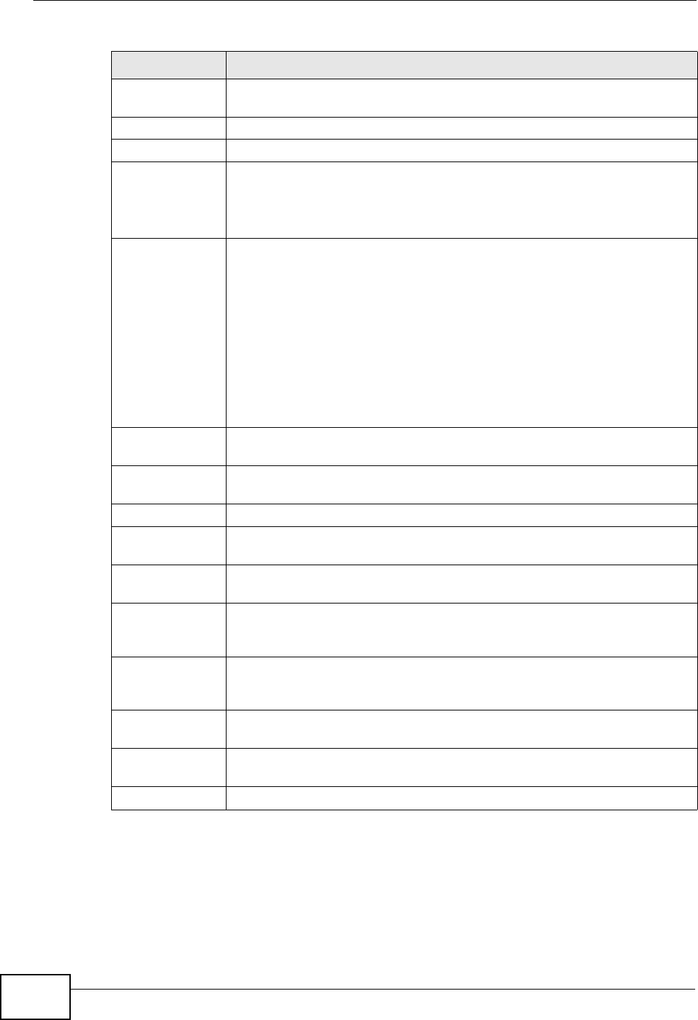
Chapter 5 Status Screens
P-2612HWU-F1 User’s Guide
100
Last Outgoing
Number This field displays the last number the SIP account called. It displays N/
A if the SIP account has never dialed a number.
Call Statistics
Phone This field displays each phone port in the ZyXEL Device.
Hook This field indicates whether the phone is on the hook or off the hook.
On - The phone is hanging up or already hung up.
Off - The phone is dialing, calling, or connected.
Status This field displays the current state of the phone call.
N/A - There are no current VoIP calls, incoming calls or outgoing calls
being made.
DIAL - The callee’s phone is ringing.
RING - The phone is ringing for an incoming VoIP call.
Process - There is a VoIP call in progress.
DISC - The callee’s line is busy, the callee hung up or your phone was
left off the hook.
Codec This field displays what voice codec is being used for a current VoIP call
through a phone port.
Peer Number This field displays the SIP number of the party that is currently engaged
in a VoIP call through a phone port.
Duration This field displays how long the current call has lasted.
Tx Pkts This field displays the number of packets the ZyXEL Device has
transmitted in the current call.
Rx Pkts This field displays the number of packets the ZyXEL Device has received
in the current call.
Tx B/s This field displays how quickly the ZyXEL Device has transmitted
packets in the current call. The rate is the average number of bytes
transmitted per second.
Rx B/s This field displays how quickly the ZyXEL Device has received packets in
the current call. The rate is the average number of bytes transmitted
per second.
Poll Interval(s) Enter how often you want the ZyXEL Device to update this screen, and
click Set Interval.
Set Interval Click this to make the ZyXEL Device update the screen based on the
amount of time you specified in Poll Interval.
Stop Click this to make the ZyXEL Device stop updating the screen.
Table 18 VoIP Statistics
LABEL DESCRIPTION
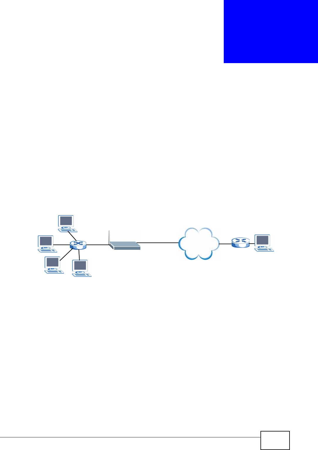
P-2612HWU-F1 User’s Guide 101
CHAPTER 6
WAN Setup
6.1 Overview
This chapter discusses the ZyXEL Device’s WAN screens. Use these screens to
configure your ZyXEL Device for Internet access.
A WAN (Wide Area Network) connection is an outside connection to another
network or the Internet. It connects your private networks (such as a LAN (Local
Area Network) and other networks, so that a computer in one location can
communicate with computers in other locations.
Figure 75 LAN and WAN
6.1.1 What You Can Do in the WAN Screens
•Use the Internet Access Setup screen (Section 6.2 on page 103) to configure
the WAN settings on the ZyXEL Device for Internet access.
•Use the WAN Backup Setup screen (Section 6.3 on page 108) to set up a
backup gateway that helps forward traffic to its destination when the default
WAN connection is down.
6.1.2 What You Need to Know About WAN
Encapsulation Method
Encapsulation is used to include data from an upper layer protocol into a lower
layer protocol. To set up a WAN connection to the Internet, you need to use the
same encapsulation method used by your ISP (Internet Service Provider). If your
Internet
WAN
LAN

Chapter 6 WAN Setup
P-2612HWU-F1 User’s Guide
102
ISP offers a dial-up Internet connection using PPPoE (PPP over Ethernet) or PPPoA,
they should also provide a username and password (and service name) for user
authentication.
WAN IP Address
The WAN IP address is an IP address for the ZyXEL Device, which makes it
accessible from an outside network. It is used by the ZyXEL Device to
communicate with other devices in other networks. It can be static (fixed) or
dynamically assigned by the ISP each time the ZyXEL Device tries to access the
Internet.
If your ISP assigns you a static WAN IP address, they should also assign you the
subnet mask and DNS server IP address(es) (and a gateway IP address if you use
the Ethernet or ENET ENCAP encapsulation method).
Finding Out More
• See Section 6.4 on page 109 for advanced technical information on WAN.
• See Chapter 4 on page 59 for WAN tutorials.
6.1.3 Before You Begin
You need to know your Internet access settings such as encapsulation and WAN IP
address. Get this information from your ISP.
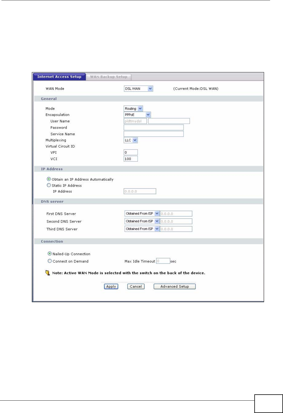
Chapter 6 WAN Setup
P-2612HWU-F1 User’s Guide 103
6.2 The Internet Access Setup Screen
Use this screen to change your ZyXEL Device’s WAN settings. Click Network >
WAN > Internet Access Setup. The screen differs by the WAN mode and
encapsulation you select.
Figure 76 Network > WAN > Internet Access Setup (PPPoE)

Chapter 6 WAN Setup
P-2612HWU-F1 User’s Guide
104
The following table describes the labels in this screen.
Table 19 Network > WAN > Internet Access Setup
LABEL DESCRIPTION
WAN Mode Set the WAN mode to DSL WAN or Ethernet WAN using the DSL/
WAN switch on the back of the ZyXEL Device.
When you set the DSL/WAN switch to the DSL side, the ZyXEL
Device restarts automatically and this shows DSL WAN. The WAN
port will be disabled automatically.
When you set the DSL/WAN switch to the WAN side, the ZyXEL
Device restarts automatically and this shows Ethernet WAN. The
DSL port will be disabled automatically. This allows the ZyXEL Device
to work as an Ethernet gateway, instead of a DSL router. To access the
Internet, connect the WAN port to a broadband modem or router.
General
Mode This field is not available if you set the WAN mode to Ethernet WAN.
Select Routing (default) from the drop-down list box if your ISP give
you one IP address only and you want multiple computers to share an
Internet account. Select Bridge when your ISP provides you more
than one IP address and you want the connected computers to get
individual IP address from ISP’s DHCP server directly. If you select
Bridge, you cannot use Firewall, DHCP server and NAT on the ZyXEL
Device.
Encapsulation Select the method of encapsulation used by your ISP from the drop-
down list box. Choices vary depending on the mode you select in the
Mode field.
If you set the WAN mode to DSL WAN and select Bridge in the Mode
field, select PPPoA or RFC 1483.
If you set the WAN mode to DSL WAN and select Routing in the
Mode field, select PPPoA, ENET ENCAP or PPPoE.
If you set the WAN mode to Ethernet WAN, select ENET ENCAP or
PPPoE.
User Name (PPPoE or PPPoA encapsulation only) Enter the user name exactly as
your ISP assigned. If assigned a name in the form user@domain
where domain identifies a service name, then enter both components
exactly as given.
Password (PPPoE or PPPoA encapsulation only) Enter the password associated
with the user name above.
Service Name (PPPoE only) Type the name of your PPPoE service here.
Multiplexing This field is not available if you set the WAN mode to Ethernet WAN.
Select the method of multiplexing used by your ISP from the drop-
down list. Choices are VC or LLC.
Virtual Circuit ID These fields are not available if you set the WAN mode to Ethernet
WAN.
VPI (Virtual Path Identifier) and VCI (Virtual Channel Identifier) define
a virtual circuit. Refer to the appendix for more information.
VPI The valid range for the VPI is 0 to 255. Enter the VPI assigned to you.
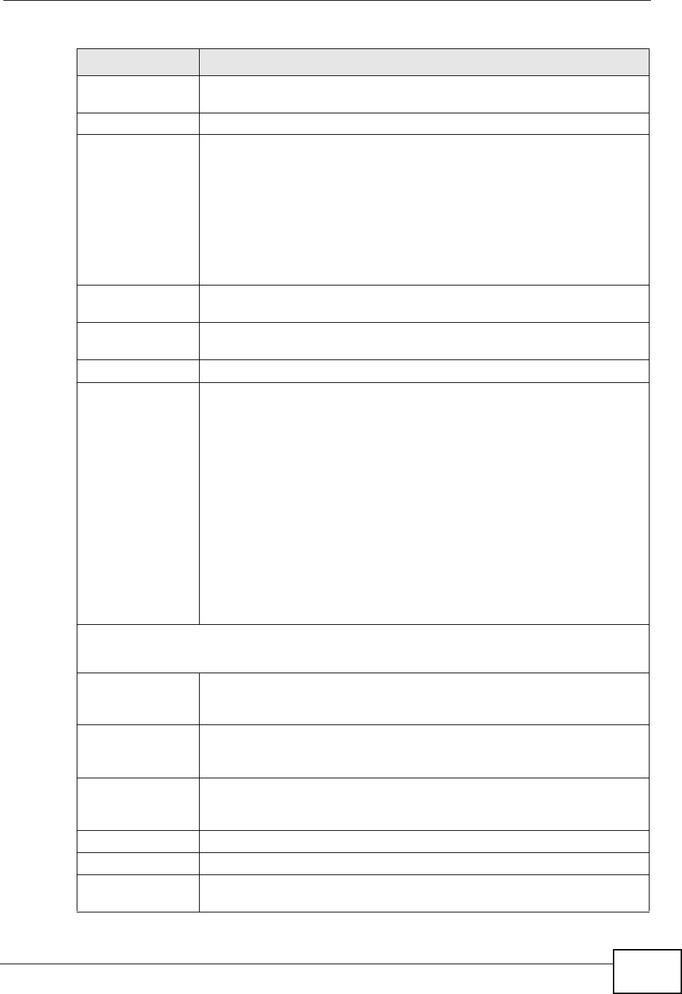
Chapter 6 WAN Setup
P-2612HWU-F1 User’s Guide 105
VCI The valid range for the VCI is 32 to 65535 (0 to 31 is reserved for
local management of ATM traffic). Enter the VCI assigned to you.
IP Address
IP Address This option is available if you set the WAN mode to Ethernet WAN or
select Routing in the Mode field.
A static IP address is a fixed IP that your ISP gives you. A dynamic IP
address is not fixed; the ISP assigns you a different one each time you
connect to the Internet.
Select Obtain an IP Address Automatically if you have a dynamic
IP address; otherwise select Static IP Address and type your ISP
assigned IP address in the IP Address field below.
Subnet Mask Enter a subnet mask in dotted decimal notation when you select
DHCP in the Encapsulation field.
Gateway IP
address You must specify a gateway IP address (supplied by your ISP) when
you select DHCP in the Encapsulation field.
DNS Server
First DNS Server
Second DNS
Server
Third DNS Server
Select Obtained From ISP if your ISP dynamically assigns DNS
server information (and the ZyXEL Device's WAN IP address) and you
select Obtain an IP Address Automatically.
Select UserDefined if you have the IP address of a DNS server. Enter
the DNS server's IP address in the field to the right. If you chose
UserDefined, but leave the IP address set to 0.0.0.0, UserDefined
changes to None after you click Apply. If you set a second choice to
User-Defined, and enter the same IP address, the second
UserDefined changes to None after you click Apply.
Select None if you do not want to configure DNS servers. You must
have another DNS server on your LAN, or else the computers must
have their DNS server addresses manually configured. If you do not
configure a DNS server, you must know the IP address of a computer
in order to access it.
Connection
(PPPoE encapsulation only)
Nailed-Up
Connection Select Nailed-Up Connection when you want your connection up all
the time. The ZyXEL Device will try to bring up the connection
automatically if it is disconnected.
Connect on
Demand Select Connect on Demand when you don't want the connection up
all the time and specify an idle time-out in the Max Idle Timeout
field.
Max Idle Timeout Specify an idle time-out in the Max Idle Timeout field when you
select Connect on Demand. The default setting is 0, which means
the Internet session will not timeout.
Apply Click Apply to save the changes.
Cancel Click Cancel to begin configuring this screen afresh.
Advanced Setup Click this button to display the Advanced WAN Setup screen and
edit more details of your WAN setup.
Table 19 Network > WAN > Internet Access Setup (continued)
LABEL DESCRIPTION
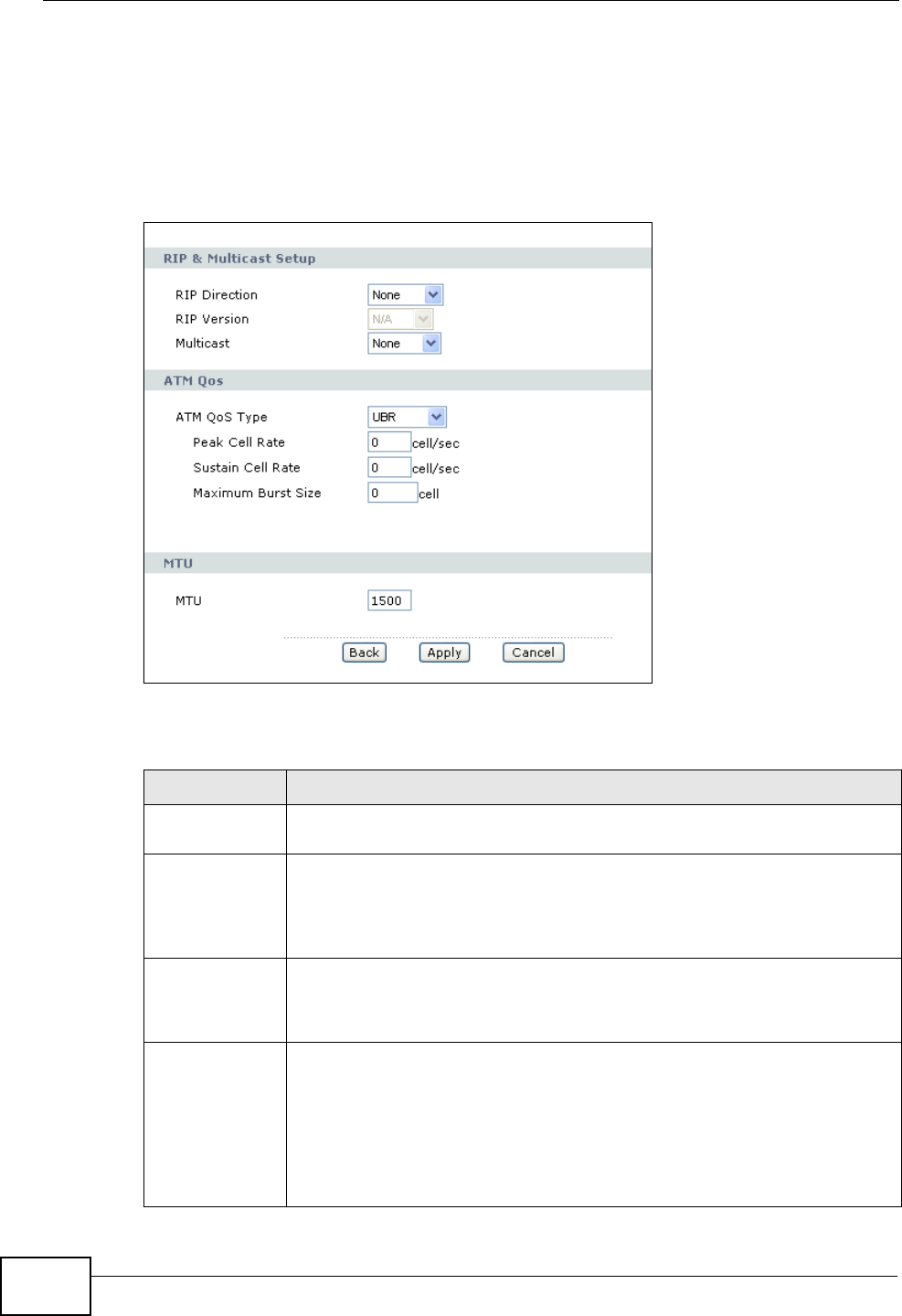
Chapter 6 WAN Setup
P-2612HWU-F1 User’s Guide
106
6.2.1 Advanced Internet Access Setup
Use this screen to edit your ZyXEL Device's advanced WAN settings. Click the
Advanced Setup button in the Internet Access Setup screen. The screen
appears as shown.
Figure 77 Network > WAN > Internet Access Setup: Advanced Setup
The following table describes the labels in this screen.
Table 20 Network > WAN > Internet Access Setup: Advanced Setup
LABEL DESCRIPTION
RIP & Multicast
Setup This section is not available when you configure the ZyXEL Device to be
in bridge mode.
RIP Direction RIP (Routing Information Protocol) allows a router to exchange routing
information with other routers. Use this field to control how much
routing information the ZyXEL Device sends and receives on the subnet.
Select the RIP direction from None, Both, In Only and Out Only.
RIP Version This field is not configurable if you select None in the RIP Direction
field.
Select the RIP version from RIP-1, RIP-2B and RIP-2M.
Multicast Multicast packets are sent to a group of computers on the LAN and are
an alternative to unicast packets (packets sent to one computer) and
broadcast packets (packets sent to every computer).
IGMP (Internet Group Multicast Protocol) is a network-layer protocol
used to establish membership in a multicast group. The ZyXEL Device
supports both IGMP version 1 (IGMP-v1) and IGMP-v2. Select None
to disable it.

Chapter 6 WAN Setup
P-2612HWU-F1 User’s Guide 107
ATM QoS
ATM QoS Type These fields are not available if you set the WAN mode to Ethernet
WAN.
Select CBR (Continuous Bit Rate) to specify fixed (always-on) bandwidth
for voice or data traffic. Select UBR (Unspecified Bit Rate) for
applications that are non-time sensitive, such as e-mail. Select VBR-RT
(real-time Variable Bit Rate) type for applications with bursty
connections that require closely controlled delay and delay variation.
Select VBR-nRT (non real-time Variable Bit Rate) type for connections
that do not require closely controlled delay and delay variation.
Peak Cell
Rate Divide the DSL line rate (bps) by 424 (the size of an ATM cell) to find the
Peak Cell Rate (PCR). This is the maximum rate at which the sender can
send cells. Type the PCR here.
Sustain Cell
Rate The Sustained Cell Rate (SCR) sets the average cell rate (long-term)
that can be transmitted. Type the SCR, which must be less than the PCR.
Note that system default is 0 cells/sec.
Maximum
Burst Size Maximum Burst Size (MBS) refers to the maximum number of cells that
can be sent at the peak rate. Type the MBS, which is less than 65535.
MTU The Maximum Transmission Unit (MTU) defines the size of the largest
packet allowed on an interface or connection. Enter the MTU in this field.
For ENET ENCAP, the MTU value is 1500.
For PPPoE, the MTU value is 1492.
For PPPoA and RFC 1483, the MTU is 65535.
Back Click Back to return to the previous screen.
Apply Click Apply to save the changes.
Cancel Click Cancel to begin configuring this screen afresh.
Table 20 Network > WAN > Internet Access Setup: Advanced Setup (continued)
LABEL DESCRIPTION
Chapter 6 WAN Setup
P-2612HWU-F1 User’s Guide
108
6.3 The WAN Backup Setup Screen
Use this screen to configure your ZyXEL Device’s WAN backup. Click Network >
WAN > WAN Backup Setup. This screen is not available if you set the WAN
mode to Ethernet WAN in the Internet Access Setup screen.
Figure 78 Network > WAN > WAN Backup Setup
The following table describes the labels in this screen.
Table 21 Network > WAN > WAN Backup
LABEL DESCRIPTION
Backup Type Select the method that the ZyXEL Device uses to check the DSL
connection.
Select DSL Link to have the ZyXEL Device check if the connection to the
DSLAM is up. Select ICMP to have the ZyXEL Device periodically ping
the IP addresses configured in the Check WAN IP Address fields.
Check WAN IP
Address1-3 Configure this field to test your ZyXEL Device's WAN accessibility. Type
the IP address of a reliable nearby computer (for example, your ISP's
DNS server address).
Note: If you activate either traffic redirect or dial backup, you must
configure at least one IP address here.
When using a WAN backup connection, the ZyXEL Device periodically
pings the addresses configured here and uses the other WAN backup
connection (if configured) if there is no response.
Fail Tolerance Type the number of times (2 recommended) that your ZyXEL Device
may ping the IP addresses configured in the Check WAN IP Address
field without getting a response before switching to a WAN backup
connection (or a different WAN backup connection).

Chapter 6 WAN Setup
P-2612HWU-F1 User’s Guide 109
6.4 WAN Technical Reference
This section provides some technical background information about the topics
covered in this chapter.
6.4.1 Encapsulation
Be sure to use the encapsulation method required by your ISP. The ZyXEL Device
supports the following methods.
Recovery
Interval When the ZyXEL Device is using a lower priority connection (usually a
WAN backup connection), it periodically checks whether or not it can use
a higher priority connection.
Type the number of seconds (30 recommended) for the ZyXEL Device to
wait between checks. Allow more time if your destination IP address
handles lots of traffic.
Timeout Type the number of seconds (3 recommended) for your ZyXEL Device to
wait for a ping response from one of the IP addresses in the Check
WAN IP Address field before timing out the request. The WAN
connection is considered "down" after the ZyXEL Device times out the
number of times specified in the Fail Tolerance field. Use a higher
value in this field if your network is busy or congested.
Traffic Redirect Traffic redirect forwards traffic to a backup gateway when the ZyXEL
Device cannot connect to the Internet.
Active Traffic
Redirect Select this check box to have the ZyXEL Device use traffic redirect if the
normal WAN connection goes down.
Note: If you activate traffic redirect, you must configure at least one
Check WAN IP Address.
Metric This field sets this route's priority among the routes the ZyXEL Device
uses.
The metric represents the "cost of transmission". A router determines
the best route for transmission by choosing a path with the lowest
"cost". RIP routing uses hop count as the measurement of cost, with a
minimum of "1" for directly connected networks. The number must be
between "1" and "15"; a number greater than "15" means the link is
down. The smaller the number, the lower the "cost".
Backup
Gateway Type the IP address of your backup gateway in dotted decimal notation.
The ZyXEL Device automatically forwards traffic to this IP address if the
ZyXEL Device's Internet connection terminates.
Apply Click Apply to save the changes.
Cancel Click Cancel to begin configuring this screen afresh.
Table 21 Network > WAN > WAN Backup
LABEL DESCRIPTION

Chapter 6 WAN Setup
P-2612HWU-F1 User’s Guide
110
6.4.1.1 ENET ENCAP
The MAC Encapsulated Routing Link Protocol (ENET ENCAP) is only implemented
with the IP network protocol. IP packets are routed between the Ethernet interface
and the WAN interface and then formatted so that they can be understood in a
bridged environment. For instance, it encapsulates routed Ethernet frames into
bridged ATM cells. ENET ENCAP requires that you specify a gateway IP address in
the Gateway IP Address field in the wizard or WAN screen. You can get this
information from your ISP.
6.4.1.2 PPP over Ethernet
The ZyXEL Device supports PPPoE (Point-to-Point Protocol over Ethernet). PPPoE is
an IETF Draft standard (RFC 2516) specifying how a personal computer (PC)
interacts with a broadband modem (DSL, cable, wireless, and so on.) connection.
The PPPoE option is for a dial-up connection using PPPoE.
For the service provider, PPPoE offers an access and authentication method that
works with existing access control systems (for example RADIUS).
One of the benefits of PPPoE is the ability to let you access one of multiple network
services, a function known as dynamic service selection. This enables the service
provider to easily create and offer new IP services for individuals.
Operationally, PPPoE saves significant effort for both you and the ISP or carrier, as
it requires no specific configuration of the broadband modem at the customer site.
By implementing PPPoE directly on the ZyXEL Device (rather than individual
computers), the computers on the LAN do not need PPPoE software installed,
since the ZyXEL Device does that part of the task. Furthermore, with NAT, all of
the LANs’ computers will have access.
6.4.1.3 PPPoA
PPPoA stands for Point to Point Protocol over ATM Adaptation Layer 5 (AAL5). A
PPPoA connection functions like a dial-up Internet connection. The ZyXEL Device
encapsulates the PPP session based on RFC1483 and sends it through an ATM PVC
(Permanent Virtual Circuit) to the Internet Service Provider’s (ISP) DSLAM (Digital
Subscriber Line (DSL) Access Multiplexer). Please refer to RFC 2364 for more
information on PPPoA. Refer to RFC 1661 for more information on PPP.
6.4.1.4 RFC 1483
RFC 1483 describes two methods for Multiprotocol Encapsulation over ATM
Adaptation Layer 5 (AAL5). The first method allows multiplexing of multiple
protocols over a single ATM virtual circuit (LLC-based multiplexing) and the second

Chapter 6 WAN Setup
P-2612HWU-F1 User’s Guide 111
method assumes that each protocol is carried over a separate ATM virtual circuit
(VC-based multiplexing). Please refer to RFC 1483 for more detailed information.
6.4.2 Multiplexing
There are two conventions to identify what protocols the virtual circuit (VC) is
carrying. Be sure to use the multiplexing method required by your ISP.
VC-based Multiplexing
In this case, by prior mutual agreement, each protocol is assigned to a specific
virtual circuit; for example, VC1 carries IP, and so on. VC-based multiplexing may
be dominant in environments where dynamic creation of large numbers of ATM
VCs is fast and economical.
LLC-based Multiplexing
In this case one VC carries multiple protocols with protocol identifying information
being contained in each packet header. Despite the extra bandwidth and
processing overhead, this method may be advantageous if it is not practical to
have a separate VC for each carried protocol, for example, if charging heavily
depends on the number of simultaneous VCs.
6.4.3 VPI and VCI
Be sure to use the correct Virtual Path Identifier (VPI) and Virtual Channel
Identifier (VCI) numbers assigned to you. The valid range for the VPI is 0 to 255
and for the VCI is 32 to 65535 (0 to 31 is reserved for local management of ATM
traffic). Please see the appendix for more information.
6.4.4 IP Address Assignment
A static IP is a fixed IP that your ISP gives you. A dynamic IP is not fixed; the ISP
assigns you a different one each time. The Single User Account feature can be
enabled or disabled if you have either a dynamic or static IP. However the
encapsulation method assigned influences your choices for IP address and ENET
ENCAP gateway.
IP Assignment with PPPoA or PPPoE Encapsulation
If you have a dynamic IP, then the IP Address and Gateway IP Address fields
are not applicable (N/A). If you have a static IP, then you only need to fill in the IP
Address field and not the Gateway IP Address field.

Chapter 6 WAN Setup
P-2612HWU-F1 User’s Guide
112
IP Assignment with RFC 1483 Encapsulation
In this case the IP address assignment must be static.
IP Assignment with ENET ENCAP Encapsulation
In this case you can have either a static or dynamic IP. For a static IP you must fill
in all the IP Address and Gateway IP Address fields as supplied by your ISP.
However for a dynamic IP, the ZyXEL Device acts as a DHCP client on the WAN
port and so the IP Address and Gateway IP Address fields are not applicable
(N/A) as the DHCP server assigns them to the ZyXEL Device.
6.4.5 Nailed-Up Connection (PPP)
A nailed-up connection is a dial-up line where the connection is always up
regardless of traffic demand. The ZyXEL Device does two things when you specify
a nailed-up connection. The first is that idle timeout is disabled. The second is that
the ZyXEL Device will try to bring up the connection when turned on and
whenever the connection is down. A nailed-up connection can be very expensive
for obvious reasons.
Do not specify a nailed-up connection unless your telephone company offers flat-
rate service or you need a constant connection and the cost is of no concern.
6.4.6 NAT
NAT (Network Address Translation - NAT, RFC 1631) is the translation of the IP
address of a host in a packet, for example, the source address of an outgoing
packet, used within one network to a different IP address known within another
network.
6.4.7 Metric
The metric represents the "cost of transmission". A router determines the best
route for transmission by choosing a path with the lowest "cost". RIP routing uses
hop count as the measurement of cost, with a minimum of "1" for directly
connected networks. The number must be between "1" and "15"; a number
greater than "15" means the link is down. The smaller the number, the lower the
"cost".
The metric sets the priority for the ZyXEL Device’s routes to the Internet. For
example, if the normal route has a metric of "1" and the traffic-redirect route has
a metric of "2", then the normal route acts as the primary default route. If the
normal route fails to connect to the Internet, the ZyXEL Device tries the traffic-
redirect route next.
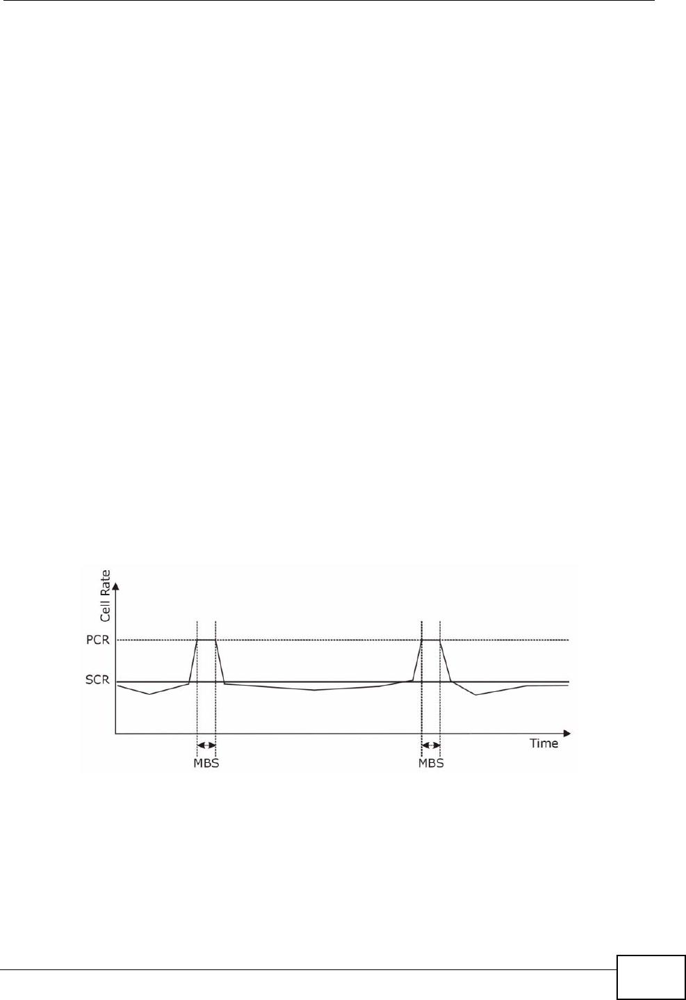
Chapter 6 WAN Setup
P-2612HWU-F1 User’s Guide 113
6.4.8 Traffic Shaping
Traffic Shaping is an agreement between the carrier and the subscriber to regulate
the average rate and fluctuations of data transmission over an ATM network. This
agreement helps eliminate congestion, which is important for transmission of real
time data such as audio and video connections.
Peak Cell Rate (PCR) is the maximum rate at which the sender can send cells. This
parameter may be lower (but not higher) than the maximum line speed. 1 ATM
cell is 53 bytes (424 bits), so a maximum speed of 832Kbps gives a maximum
PCR of 1962 cells/sec. This rate is not guaranteed because it is dependent on the
line speed.
Sustained Cell Rate (SCR) is the mean cell rate of each bursty traffic source. It
specifies the maximum average rate at which cells can be sent over the virtual
connection. SCR may not be greater than the PCR.
Maximum Burst Size (MBS) is the maximum number of cells that can be sent at
the PCR. After MBS is reached, cell rates fall below SCR until cell rate averages to
the SCR again. At this time, more cells (up to the MBS) can be sent at the PCR
again.
If the PCR, SCR or MBS is set to the default of "0", the system will assign a
maximum value that correlates to your upstream line rate.
The following figure illustrates the relationship between PCR, SCR and MBS.
Figure 79 Example of Traffic Shaping
6.4.8.1 ATM Traffic Classes
These are the basic ATM traffic classes defined by the ATM Forum Traffic
Management 4.0 Specification.

Chapter 6 WAN Setup
P-2612HWU-F1 User’s Guide
114
Constant Bit Rate (CBR)
Constant Bit Rate (CBR) provides fixed bandwidth that is always available even if
no data is being sent. CBR traffic is generally time-sensitive (doesn't tolerate
delay). CBR is used for connections that continuously require a specific amount of
bandwidth. A PCR is specified and if traffic exceeds this rate, cells may be
dropped. Examples of connections that need CBR would be high-resolution video
and voice.
Variable Bit Rate (VBR)
The Variable Bit Rate (VBR) ATM traffic class is used with bursty connections.
Connections that use the Variable Bit Rate (VBR) traffic class can be grouped into
real time (VBR-RT) or non-real time (VBR-nRT) connections.
The VBR-RT (real-time Variable Bit Rate) type is used with bursty connections that
require closely controlled delay and delay variation. It also provides a fixed
amount of bandwidth (a PCR is specified) but is only available when data is being
sent. An example of an VBR-RT connection would be video conferencing. Video
conferencing requires real-time data transfers and the bandwidth requirement
varies in proportion to the video image's changing dynamics.
The VBR-nRT (non real-time Variable Bit Rate) type is used with bursty
connections that do not require closely controlled delay and delay variation. It is
commonly used for "bursty" traffic typical on LANs. PCR and MBS define the burst
levels, SCR defines the minimum level. An example of an VBR-nRT connection
would be non-time sensitive data file transfers.
Unspecified Bit Rate (UBR)
The Unspecified Bit Rate (UBR) ATM traffic class is for bursty data transfers.
However, UBR doesn't guarantee any bandwidth and only delivers traffic when the
network has spare bandwidth. An example application is background file transfer.
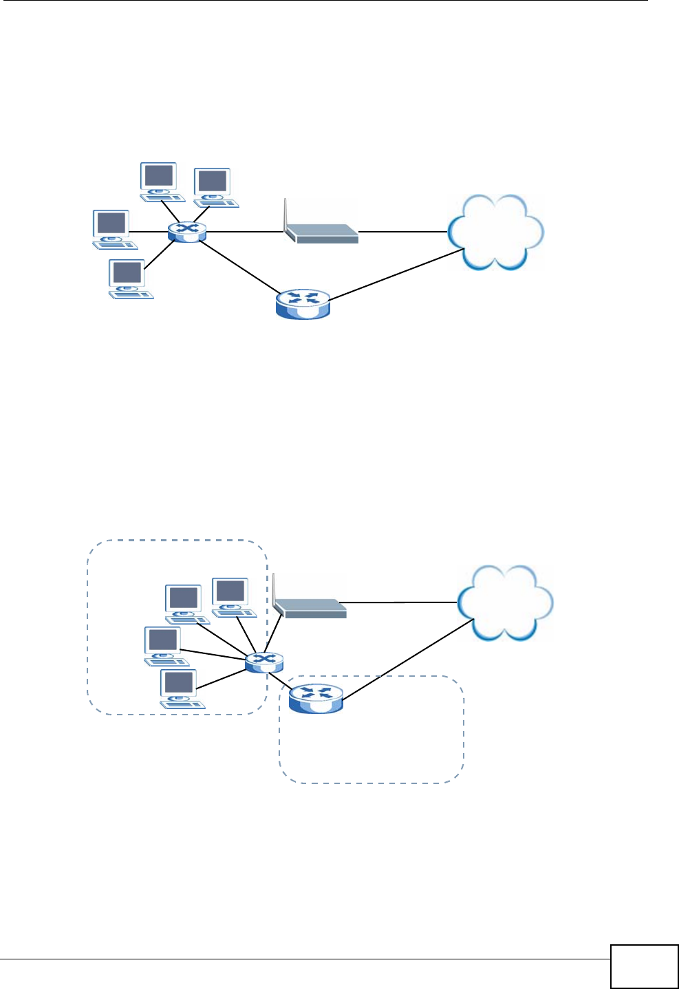
Chapter 6 WAN Setup
P-2612HWU-F1 User’s Guide 115
6.5 Traffic Redirect
Traffic redirect forwards traffic to a backup gateway when the ZyXEL Device
cannot connect to the Internet. An example is shown in the figure below.
Figure 80 Traffic Redirect Example
The following network topology allows you to avoid triangle route security issues
when the backup gateway is connected to the LAN. Use IP alias to configure the
LAN into two or three logical networks with the ZyXEL Device itself as the gateway
for each LAN network. Put the protected LAN in one subnet (Subnet 1 in the
following figure) and the backup gateway in another subnet (Subnet 2). Configure
filters that allow packets from the protected LAN (Subnet 1) to the backup
gateway (Subnet 2).
Figure 81 Traffic Redirect LAN Setup
Internet
WAN
LAN
Backup Gateway
Internet
WAN
LAN
Backup Gateway
Subnet 2
192.168.2.0 - 192.168.2.24
Subnet 1
192.168.1.0 - 192.168.1.24

Chapter 6 WAN Setup
P-2612HWU-F1 User’s Guide
116
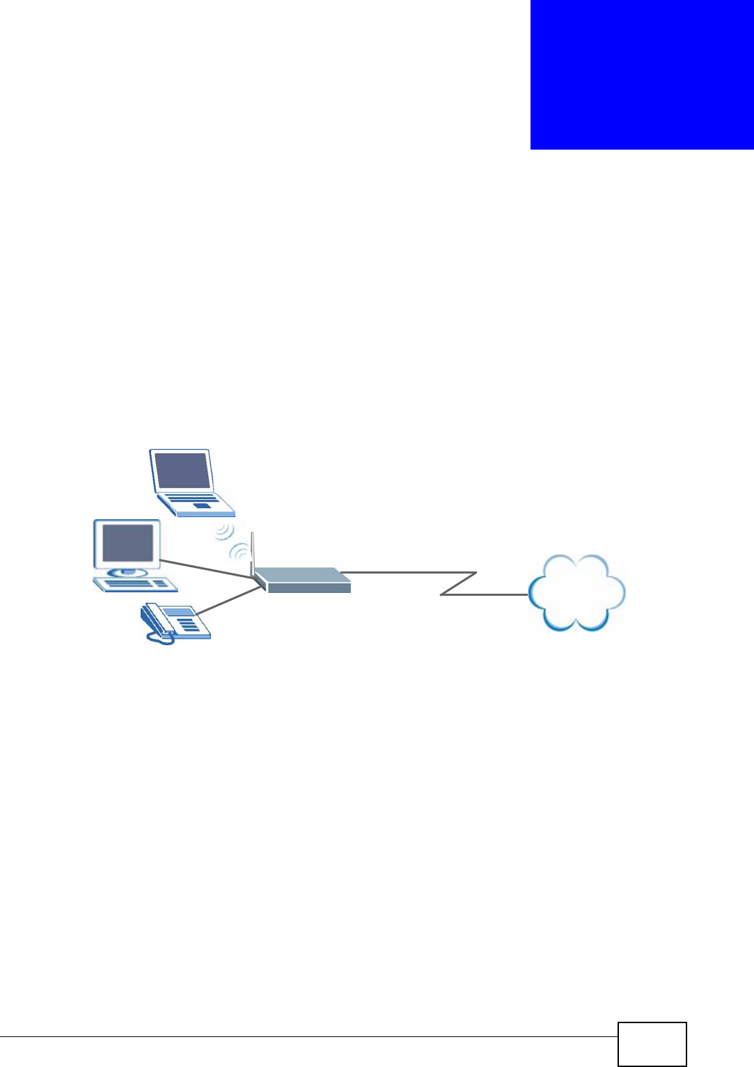
P-2612HWU-F1 User’s Guide 117
CHAPTER 7
LAN Setup
7.1 Overview
A Local Area Network (LAN) is a shared communication system to which many
computers are attached. A LAN is usually located in one immediate area such as a
building or floor of a building.
The LAN screens can help you configure a LAN DHCP server and manage IP
addresses.
• See Section 7.5 on page 125 for more information on LANs.
• See Appendix C on page 521 for more information on IP addresses and
subnetting.
7.1.1 What You Can Do in the LAN Screens
•Use the LAN IP screen (Section 7.2 on page 118) to set the LAN IP address and
subnet mask of your ZyXEL device. You can also edit your ZyXEL Device's RIP,
multicast, any IP, DHCP, and Windows Networking settings from this screen.
•Use the Client List screen (Section 7.3 on page 122) to assign IP addresses on
the LAN to specific individual computers based on their MAC Addresses.
•Use the IP Alias screen (Section 7.4 on page 124) to change your ZyXEL
Device’s IP alias settings.
Internet
DSL
LAN

Chapter 7 LAN Setup
P-2612HWU-F1 User’s Guide
118
7.1.2 What You Need To Know About LAN
IP Address
Similar to the way houses on a street share a common street name, so too do
computers on a LAN share one common network number. This is known as an
Internet Protocol address.
Subnet Mask
The subnet mask specifies the network number portion of an IP address. Your
ZyXEL Device will compute the subnet mask automatically based on the IP
address that you entered. You don't need to change the subnet mask computed by
the ZyXEL Device unless you are instructed to do otherwise.
DHCP
DHCP (Dynamic Host Configuration Protocol) allows clients to obtain TCP/IP
configuration at start-up from a server. This ZyXEL Device has a built-in DHCP
server capability that assigns IP addresses and DNS servers to systems that
support DHCP client capability.
DNS
DNS (Domain Name System) maps a domain name to its corresponding IP
address and vice versa. The DNS server is extremely important because without
it, you must know the IP address of a computer before you can access it. The DNS
server addresses you enter when you set up DHCP are passed to the client
machines along with the assigned IP address and subnet mask.
7.1.3 Before You Begin
Find out the MAC addresses of your network devices if you intend to add them to
the DHCP Client List screen.
7.2 The LAN IP Screen
Click Network > LAN to open the IP screen. See Section 7.1 on page 117 for
background information. Use this screen to set the Local Area Network IP address
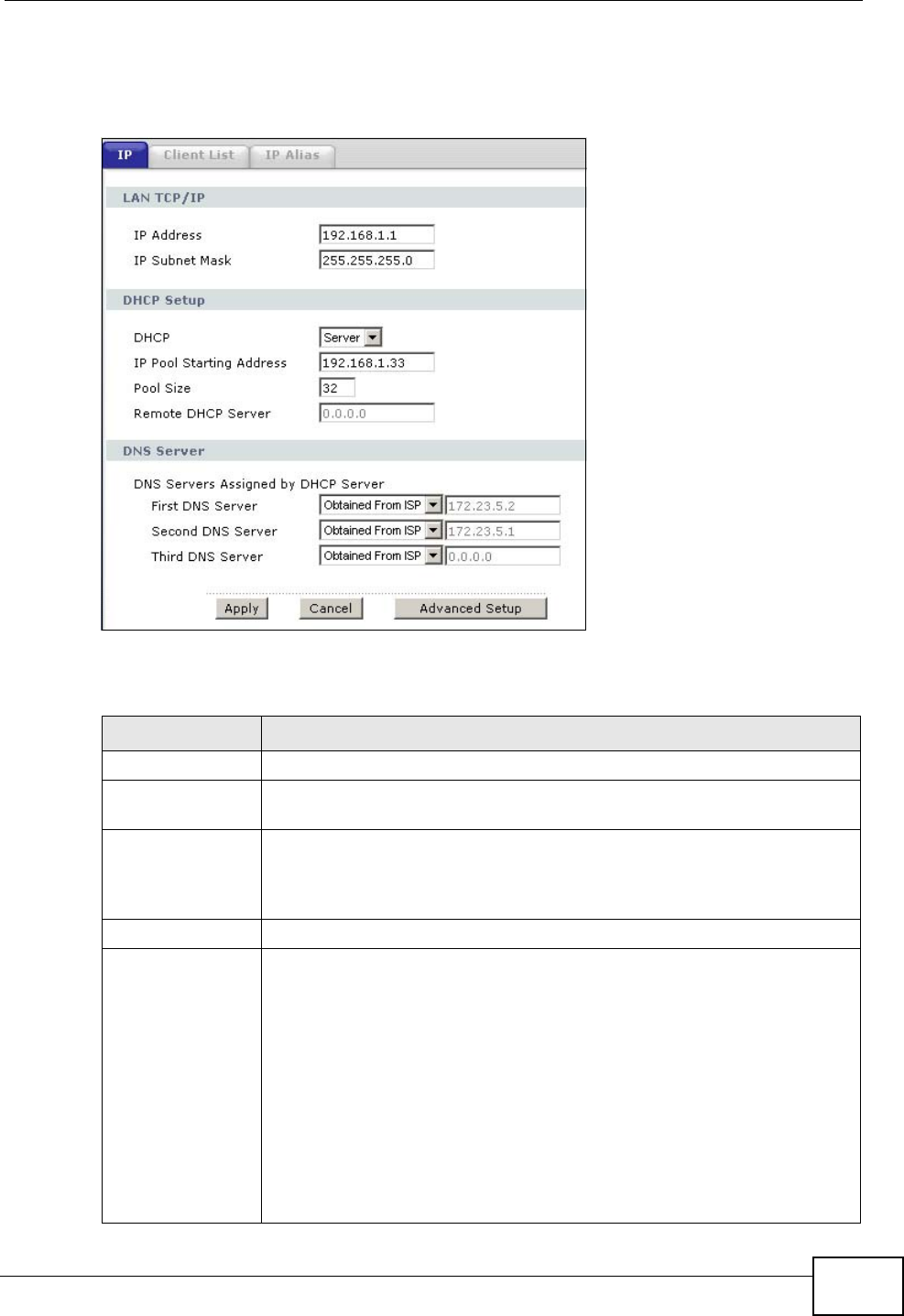
Chapter 7 LAN Setup
P-2612HWU-F1 User’s Guide 119
and subnet mask of your ZyXEL Device and configure the DNS server information
that the ZyXEL Device sends to the DHCP client devices on the LAN.
Figure 82 Network > LAN > IP
The following table describes the fields in this screen.
Table 22 Network > LAN > IP
LABEL DESCRIPTION
LAN TCP/IP
IP Address Enter the LAN IP address you want to assign to your ZyXEL Device in
dotted decimal notation, for example, 192.168.1.1 (factory default).
IP Subnet Mask Type the subnet mask of your network in dotted decimal notation, for
example 255.255.255.0 (factory default). Your ZyXEL Device
automatically computes the subnet mask based on the IP address you
enter, so do not change this field unless you are instructed to do so.
DHCP Setup
DHCP If set to Server, your ZyXEL Device can assign IP addresses, an IP
default gateway and DNS servers to LAN computers and other devices
that are DHCP clients.
If set to None, the DHCP server will be disabled. You need to manually
configure the IP addresses of the computers and other devices on your
LAN.
If set to Relay, the ZyXEL Device acts as a surrogate DHCP server and
relays DHCP requests and responses between the remote server and
the clients. Enter the IP address of the actual, remote DHCP server in
the Remote DHCP Server field in this case.
When DHCP is used, the following items need to be set:

Chapter 7 LAN Setup
P-2612HWU-F1 User’s Guide
120
7.2.1 The Advanced LAN Setup Screen
RIP
RIP (Routing Information Protocol) allows a router to exchange routing
information with other routers.
IP Pool Starting
Address This field specifies the first of the contiguous addresses in the IP
address pool.
Pool Size This field specifies the size, or count of the IP address pool.
Remote DHCP
Server If Relay is selected in the DHCP field above then enter the IP address
of the actual remote DHCP server here.
DNS Server
DNS Servers
Assigned by
DHCP Server
The ZyXEL Device passes a DNS (Domain Name System) server IP
address to the DHCP clients.
First DNS Server
Second DNS
Server
Third DNS Server
Select Obtained From ISP if your ISP dynamically assigns DNS
server information (and the ZyXEL Device's WAN IP address).
Select UserDefined if you have the IP address of a DNS server. Enter
the DNS server's IP address in the field to the right. If you chose
UserDefined, but leave the IP address set to 0.0.0.0, UserDefined
changes to None after you click Apply. If you set a second choice to
UserDefined, and enter the same IP address, the second User-
Defined changes to None after you click Apply.
Select DNS Relay to have the ZyXEL Device act as a DNS proxy only
when the ISP uses IPCP DNS server extensions. The ZyXEL Device's
LAN IP address displays in the field to the right (read-only). The ZyXEL
Device tells the DHCP clients on the LAN that the ZyXEL Device itself is
the DNS server. When a computer on the LAN sends a DNS query to
the ZyXEL Device, the ZyXEL Device forwards the query to the real
DNS server learned through IPCP and relays the response back to the
computer. You can only select DNS Relay for one of the three servers;
if you select DNS Relay for a second or third DNS server, that choice
changes to None after you click Apply.
Select None if you do not want to configure DNS servers. You must
have another DHCP sever on your LAN, or else the computers must
have their DNS server addresses manually configured. If you do not
configure a DNS server, you must know the IP address of a computer
in order to access it.
Apply Click Apply to save your changes back to the ZyXEL Device.
Cancel Click Cancel to begin configuring this screen afresh.
Advanced Setup Click this button to display the Advanced LAN Setup screen and edit
more details of your LAN setup.
Table 22 Network > LAN > IP (continued)
LABEL DESCRIPTION
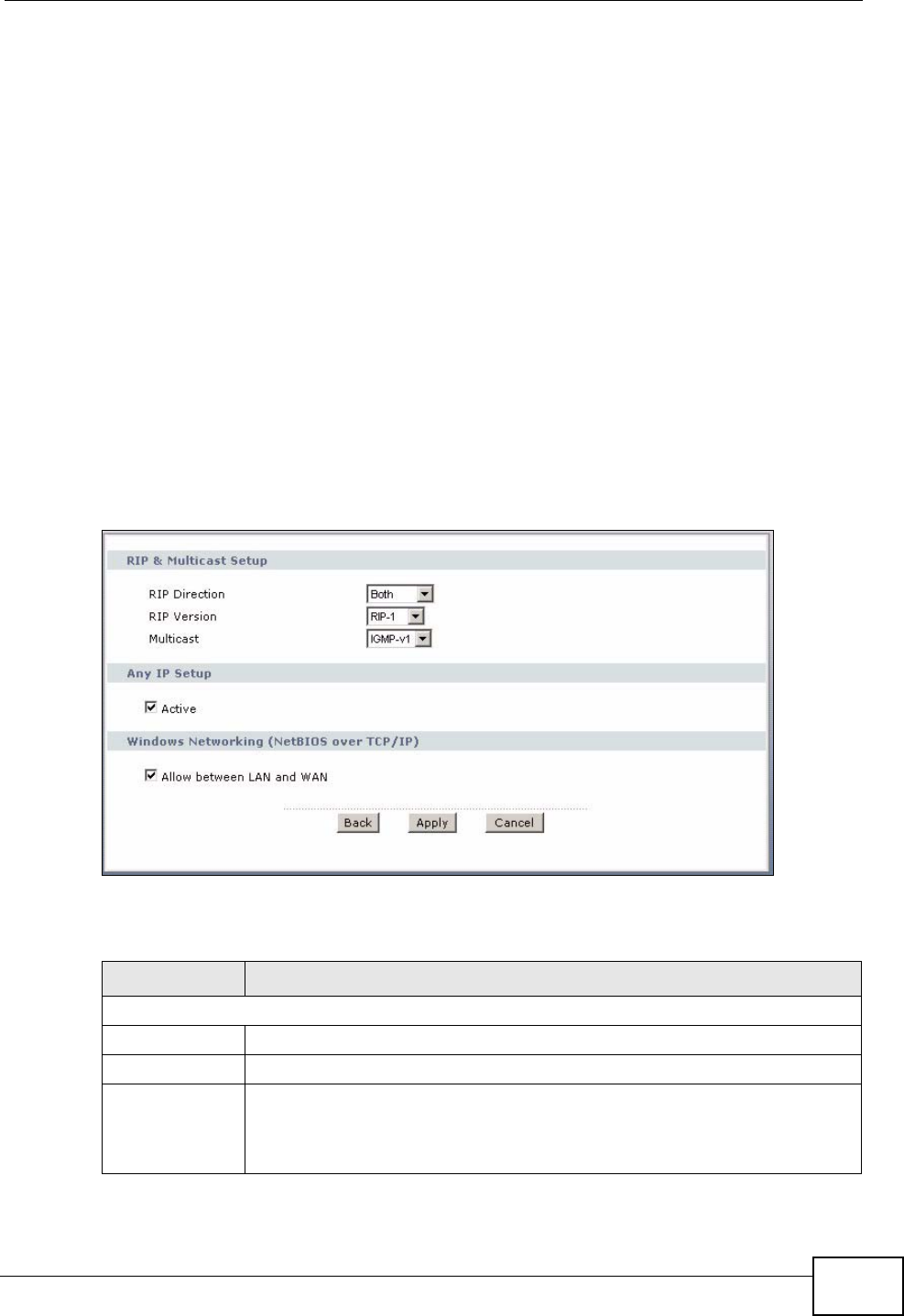
Chapter 7 LAN Setup
P-2612HWU-F1 User’s Guide 121
Multicast and IGMP
Traditionally, IP packets are transmitted in one of either two ways - Unicast (1
sender - 1 recipient) or Broadcast (1 sender - everybody on the network).
Multicast delivers IP packets to a group of hosts on the network - not everybody
and not just 1.
IGMP (Internet Group Multicast Protocol) is a network-layer protocol used to
establish membership in a Multicast group - it is not used to carry user data.
There are two versions 1 and 2. IGMP version 2 is an improvement over version 1
but IGMP version 1 is still in wide use.
7.2.2 Configuring the Advanced LAN Setup Screen
Use this screen to edit your ZyXEL Device's RIP, multicast, Any IP, and Windows
Networking settings. Click the Advanced Setup button in the LAN IP screen. The
screen appears as shown.
Figure 83 Network > LAN > IP > Advanced Setup
The following table describes the labels in this screen.
Table 23 Network > LAN > IP > Advanced Setup
LABEL DESCRIPTION
RIP & Multicast Setup
RIP Direction Select the RIP direction from None, Both, In Only and Out Only.
RIP Version Select the RIP version from RIP-1, RIP-2B and RIP-2M.
Multicast IGMP (Internet Group Multicast Protocol) is a network-layer protocol
used to establish membership in a multicast group. The ZyXEL Device
supports both IGMP version 1 (IGMP-v1) and IGMP-v2. Select None
to disable it.

Chapter 7 LAN Setup
P-2612HWU-F1 User’s Guide
122
7.3 The LAN Client List Screen
Use this table to assign IP addresses on the LAN to specific individual computers
based on their MAC Addresses.
Every Ethernet device has a unique MAC (Media Access Control) address. The MAC
address is assigned at the factory and consists of six pairs of hexadecimal
characters, for example, 00:A0:C5:00:00:02.
Any IP Setup Enable Any IP to allow a computer to access the Internet without
changing its network settings (such as IP address and subnet mask),
even when the IP addresses of the computer and the ZyXEL Device are
not in the same subnet.
When you disable Any IP, only computers with dynamic IP addresses or
static IP addresses in the same subnet as the ZyXEL Device’s LAN IP
address can connect to the ZyXEL Device or access the Internet through
the ZyXEL Device.
Windows
Networking
(NetBIOS over
TCP/IP)
NetBIOS (Network Basic Input/Output System) are TCP or UDP packets
that enable a computer to connect to and communicate with a LAN. For
some dial-up services such as PPPoE or PPTP, NetBIOS packets cause
unwanted calls. However it may sometimes be necessary to allow
NetBIOS packets to pass through to the WAN in order to find a computer
on the WAN.
Allow between
LAN and WAN Select this to forward NetBIOS packets from the LAN to the WAN and
from the WAN to the LAN. If your firewall is enabled with the default
policy set to block WAN to LAN traffic, you also need to enable the
default WAN to LAN firewall rule that forwards NetBIOS traffic.
Clear this option to block all NetBIOS packets going from the LAN to the
WAN and from the WAN to the LAN.
Back Click Back to return to the previous screen.
Apply Click Apply to save the changes.
Cancel Click Cancel to begin configuring this screen afresh.
Table 23 Network > LAN > IP > Advanced Setup (continued)
LABEL DESCRIPTION
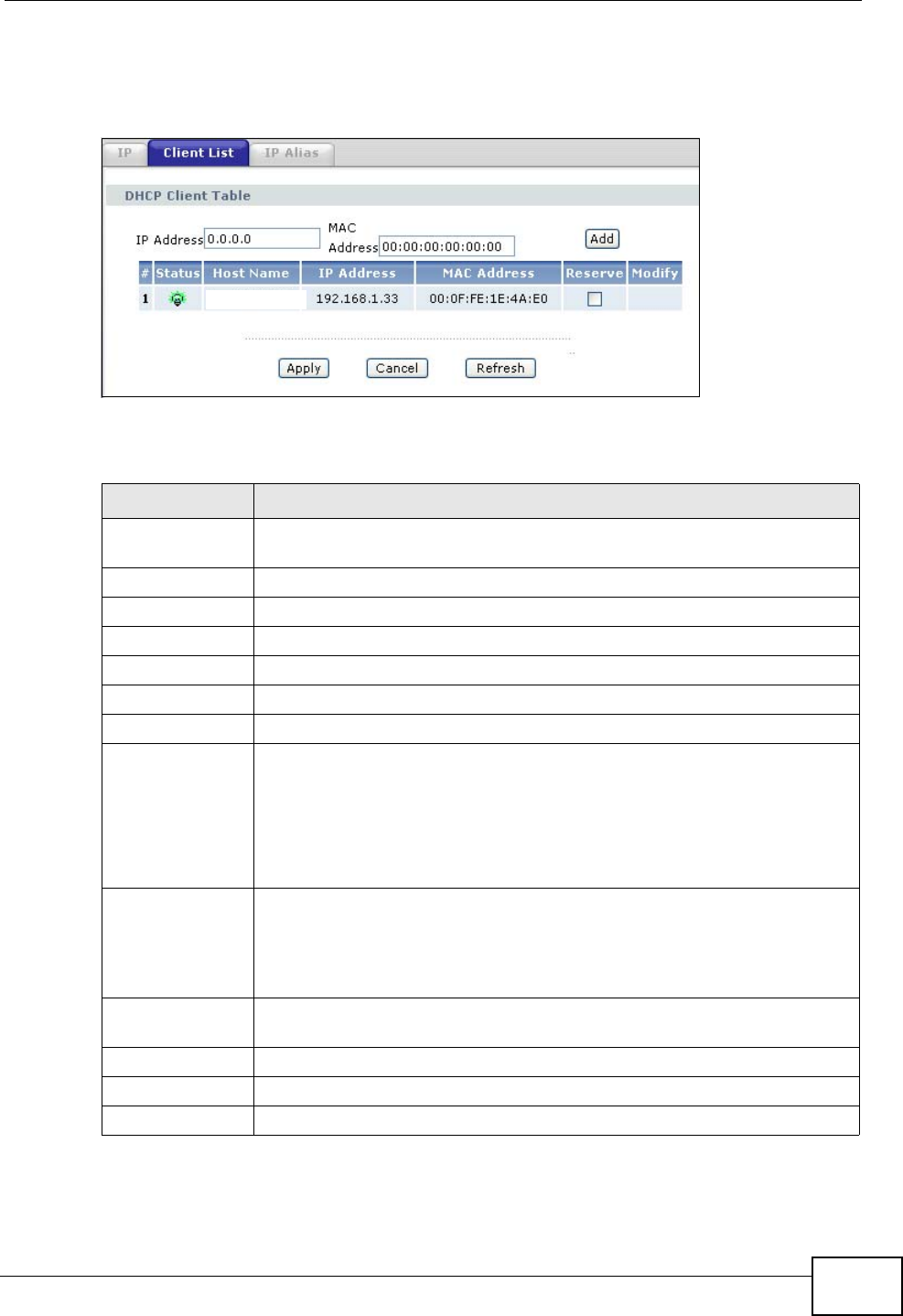
Chapter 7 LAN Setup
P-2612HWU-F1 User’s Guide 123
Click Network > LAN > Client List to open the following screen. Use this screen
to change your ZyXEL Device’s static DHCP settings.
Figure 84 Network > LAN > Client List
The following table describes the labels in this screen.
Table 24 Network > LAN > Client List
LABEL DESCRIPTION
IP Address Enter the IP address that you want to assign to the computer on your
LAN with the MAC address that you will also specify.
MAC Address Enter the MAC address of a computer on your LAN.
Add Click Add to add a static DHCP entry.
# This is the index number of the static IP table entry (row).
Status This field displays whether the client is connected to the ZyXEL Device.
Host Name This field displays the computer host name.
IP Address This field displays the IP address relative to the # field listed above.
MAC Address The MAC (Media Access Control) or Ethernet address on a LAN (Local
Area Network) is unique to your computer (six pairs of hexadecimal
notation).
A network interface card such as an Ethernet adapter has a hardwired
address that is assigned at the factory. This address follows an industry
standard that ensures no other adapter has a similar address.
Reserve Select the check box in the heading row to automatically select all
check boxes or select the check box(es) in each entry to have the
ZyXEL Device always assign the selected entry(ies)’s IP address(es) to
the corresponding MAC address(es) (and host name(s)). You can select
up to 128 entries in this table.
Modify Click the modify icon to have the IP address field editable and change
it.
Apply Click Apply to save your changes back to the ZyXEL Device.
Cancel Click Cancel to begin configuring this screen afresh.
Refresh Click Refresh to reload the DHCP table.
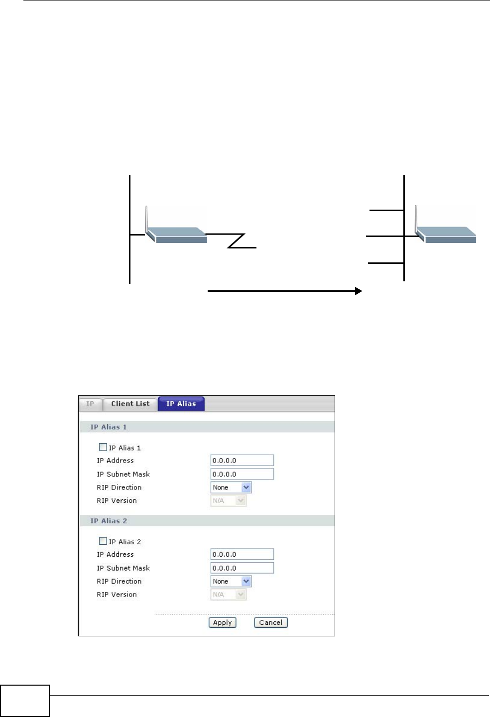
Chapter 7 LAN Setup
P-2612HWU-F1 User’s Guide
124
7.4 The LAN IP Alias Screen
IP alias partitions a physical network into different logical networks over the same
Ethernet interface. The ZyXEL Device supports three logical LAN interfaces via its
single physical Ethernet interface with the ZyXEL Device itself as the gateway for
each LAN network. With IP alias, you can also configure firewall rules to control
access between the LAN's logical networks (subnets). The following figure shows a
LAN divided into subnets A, B, and C.
Figure 85 Physical Network & Partitioned Logical Networks
Note: Make sure that the subnets of the logical networks do not overlap.
Click Network > LAN > IP Alias to open the following screen. Use this screen to
change your ZyXEL Device’s IP alias settings.
Figure 86 Network > LAN > IP Alias
Ethernet
Interface
A: 192.168.1.1 - 192.168.1.24
B: 192.168.2.1 - 192.168.2.24
C: 192.168.3.1 - 192.168.3.24

Chapter 7 LAN Setup
P-2612HWU-F1 User’s Guide 125
The following table describes the labels in this screen.
7.5 LAN Technical Reference
This section provides some technical background information about the topics
covered in this chapter.
Table 25 Network > LAN > IP Alias
LABEL DESCRIPTION
IP Alias 1, 2 Select this to configure another LAN network for the ZyXEL Device.
IP Address Enter the IP address of your ZyXEL Device in dotted decimal notation.
Alternatively, click the right mouse button to copy and/or paste the IP
address.
IP Subnet Mask Your ZyXEL Device will automatically calculate the subnet mask based
on the IP address that you assign. Unless you are implementing
subnetting, use the subnet mask computed by the ZyXEL Device.
RIP Direction RIP (Routing Information Protocol, RFC 1058 and RFC 1389) allows a
router to exchange routing information with other routers. The RIP
Direction field controls the sending and receiving of RIP packets.
Select the RIP direction from Both/In Only/Out Only/None. When
set to Both or Out Only, the ZyXEL Device will broadcast its routing
table periodically. When set to Both or In Only, it will incorporate the
RIP information that it receives; when set to None, it will not send any
RIP packets and will ignore any RIP packets received.
RIP Version The RIP Version field controls the format and the broadcasting
method of the RIP packets that the ZyXEL Device sends (it recognizes
both formats when receiving). RIP-1 is universally supported but RIP-2
carries more information. RIP-1 is probably adequate for most
networks, unless you have an unusual network topology. Both RIP-2B
and RIP-2M sends the routing data in RIP-2 format; the difference
being that RIP-2B uses subnet broadcasting while RIP-2M uses
multicasting. Multicasting can reduce the load on non-router machines
since they generally do not listen to the RIP multicast address and so
will not receive the RIP packets. However, if one router uses
multicasting, then all routers on your network must use multicasting,
also. By default, RIP direction is set to Both and the Version set to
RIP-1.
Apply Click Apply to save your changes back to the ZyXEL Device.
Cancel Click Cancel to begin configuring this screen afresh.
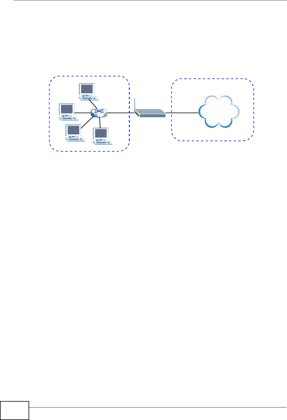
Chapter 7 LAN Setup
P-2612HWU-F1 User’s Guide
126
7.5.1 LANs, WANs and the ZyXEL Device
The actual physical connection determines whether the ZyXEL Device ports are
LAN or WAN ports. There are two separate IP networks, one inside the LAN
network and the other outside the WAN network as shown next.
Figure 87 LAN and WAN IP Addresses
7.5.2 DHCP Setup
DHCP (Dynamic Host Configuration Protocol, RFC 2131 and RFC 2132) allows
individual clients to obtain TCP/IP configuration at start-up from a server. You can
configure the ZyXEL Device as a DHCP server or disable it. When configured as a
server, the ZyXEL Device provides the TCP/IP configuration for the clients. If you
turn DHCP service off, you must have another DHCP server on your LAN, or else
the computer must be manually configured.
IP Pool
The ZyXEL Device is pre-configured with a pool of IP addresses for the DHCP
clients (DHCP Pool). See the product specifications in the appendices. Do not
assign static IP addresses from the DHCP pool to your LAN computers.
7.5.3 DNS Server Addresses
DNS (Domain Name System) maps a domain name to its corresponding IP
address and vice versa. The DNS server is extremely important because without
it, you must know the IP address of a computer before you can access it. The DNS
server addresses you enter when you set up DHCP are passed to the client
machines along with the assigned IP address and subnet mask.
There are two ways that an ISP disseminates the DNS server addresses.
Internet
WAN
LAN

Chapter 7 LAN Setup
P-2612HWU-F1 User’s Guide 127
• The ISP tells you the DNS server addresses, usually in the form of an
information sheet, when you sign up. If your ISP gives you DNS server
addresses, enter them in the DNS Server fields in the DHCP Setup screen.
• Some ISPs choose to disseminate the DNS server addresses using the DNS
server extensions of IPCP (IP Control Protocol) after the connection is up. If
your ISP did not give you explicit DNS servers, chances are the DNS servers are
conveyed through IPCP negotiation. The ZyXEL Device supports the IPCP DNS
server extensions through the DNS proxy feature.
If the DNS Server fields in the DHCP Setup screen are set to DNS Relay, the
ZyXEL Device tells the DHCP clients that it itself is the DNS server. When a
computer sends a DNS query to the ZyXEL Device, the ZyXEL Device acts as a
DNS proxy and forwards the query to the real DNS server learned through IPCP
and relays the response back to the computer.
Please note that DNS proxy works only when the ISP uses the IPCP DNS server
extensions. It does not mean you can leave the DNS servers out of the DHCP
setup under all circumstances. If your ISP gives you explicit DNS servers, make
sure that you enter their IP addresses in the DHCP Setup screen.
7.5.4 TCP/IP
The ZyXEL Device has built-in DHCP server capability that assigns IP addresses
and DNS servers to systems on the LAN that support DHCP client capability.
IP Address and Subnet Mask
Similar to the way houses on a street share a common street name, so too do
computers on a LAN share one common network number.
Where you obtain your network number depends on your particular situation. If
the ISP or your network administrator assigns you a block of registered IP
addresses, follow their instructions in selecting the IP addresses and the subnet
mask.
If the ISP did not explicitly give you an IP network number, then most likely you
have a single user account and the ISP will assign you a dynamic IP address when
the connection is established. If this is the case, it is recommended that you select
a network number from 192.168.0.0 to 192.168.255.0 and you must enable the
Network Address Translation (NAT) feature of the ZyXEL Device. The Internet
Assigned Number Authority (IANA) reserved this block of addresses specifically for
private use; please do not use any other number unless you are told otherwise.
Let's say you select 192.168.1.0 as the network number; which covers 254
individual addresses, from 192.168.1.1 to 192.168.1.254 (zero and 255 are
reserved). In other words, the first three numbers specify the network number
while the last number identifies an individual computer on that network.

Chapter 7 LAN Setup
P-2612HWU-F1 User’s Guide
128
Once you have decided on the network number, pick an IP address that is easy to
remember, for instance, 192.168.1.1, for your ZyXEL Device, but make sure that
no other device on your network is using that IP address.
The subnet mask specifies the network number portion of an IP address. Your
ZyXEL Device will compute the subnet mask automatically based on the IP
address that you entered. You don't need to change the subnet mask computed by
the ZyXEL Device unless you are instructed to do otherwise.
Private IP Addresses
Every machine on the Internet must have a unique address. If your networks are
isolated from the Internet, for example, only between your two branch offices, you
can assign any IP addresses to the hosts without problems. However, the Internet
Assigned Numbers Authority (IANA) has reserved the following three blocks of IP
addresses specifically for private networks:
• 10.0.0.0 — 10.255.255.255
• 172.16.0.0 — 172.31.255.255
• 192.168.0.0 — 192.168.255.255
You can obtain your IP address from the IANA, from an ISP or it can be assigned
from a private network. If you belong to a small organization and your Internet
access is through an ISP, the ISP can provide you with the Internet addresses for
your local networks. On the other hand, if you are part of a much larger
organization, you should consult your network administrator for the appropriate IP
addresses.
Note: Regardless of your particular situation, do not create an arbitrary IP address;
always follow the guidelines above. For more information on address
assignment, please refer to RFC 1597, “Address Allocation for Private
Internets” and RFC 1466, “Guidelines for Management of IP Address Space”.
7.5.5 RIP Setup
RIP (Routing Information Protocol) allows a router to exchange routing
information with other routers. The RIP Direction field controls the sending and
receiving of RIP packets. When set to:
•Both - the ZyXEL Device will broadcast its routing table periodically and
incorporate the RIP information that it receives.
•In Only - the ZyXEL Device will not send any RIP packets but will accept all RIP
packets received.
•Out Only - the ZyXEL Device will send out RIP packets but will not accept any
RIP packets received.

Chapter 7 LAN Setup
P-2612HWU-F1 User’s Guide 129
•None - the ZyXEL Device will not send any RIP packets and will ignore any RIP
packets received.
The Version field controls the format and the broadcasting method of the RIP
packets that the ZyXEL Device sends (it recognizes both formats when receiving).
RIP-1 is universally supported; but RIP-2 carries more information. RIP-1 is
probably adequate for most networks, unless you have an unusual network
topology.
Both RIP-2B and RIP-2M sends the routing data in RIP-2 format; the difference
being that RIP-2B uses subnet broadcasting while RIP-2M uses multicasting.
7.5.6 Multicast
Traditionally, IP packets are transmitted in one of either two ways - Unicast (1
sender - 1 recipient) or Broadcast (1 sender - everybody on the network).
Multicast delivers IP packets to a group of hosts on the network - not everybody
and not just 1.
IGMP (Internet Group Multicast Protocol) is a network-layer protocol used to
establish membership in a Multicast group - it is not used to carry user data. IGMP
version 2 (RFC 2236) is an improvement over version 1 (RFC 1112) but IGMP
version 1 is still in wide use. If you would like to read more detailed information
about interoperability between IGMP version 2 and version 1, please see sections
4 and 5 of RFC 2236. The class D IP address is used to identify host groups and
can be in the range 224.0.0.0 to 239.255.255.255. The address 224.0.0.0 is not
assigned to any group and is used by IP multicast computers. The address
224.0.0.1 is used for query messages and is assigned to the permanent group of
all IP hosts (including gateways). All hosts must join the 224.0.0.1 group in order
to participate in IGMP. The address 224.0.0.2 is assigned to the multicast routers
group.
The ZyXEL Device supports both IGMP version 1 (IGMP-v1) and IGMP version 2
(IGMP-v2). At start up, the ZyXEL Device queries all directly connected networks
to gather group membership. After that, the ZyXEL Device periodically updates
this information. IP multicasting can be enabled/disabled on the ZyXEL Device LAN
and/or WAN interfaces in the web configurator (LAN; WAN). Select None to
disable IP multicasting on these interfaces.
7.5.7 Any IP
Traditionally, you must set the IP addresses and the subnet masks of a computer
and the ZyXEL Device to be in the same subnet to allow the computer to access
the Internet (through the ZyXEL Device). In cases where your computer is
required to use a static IP address in another network, you may need to manually
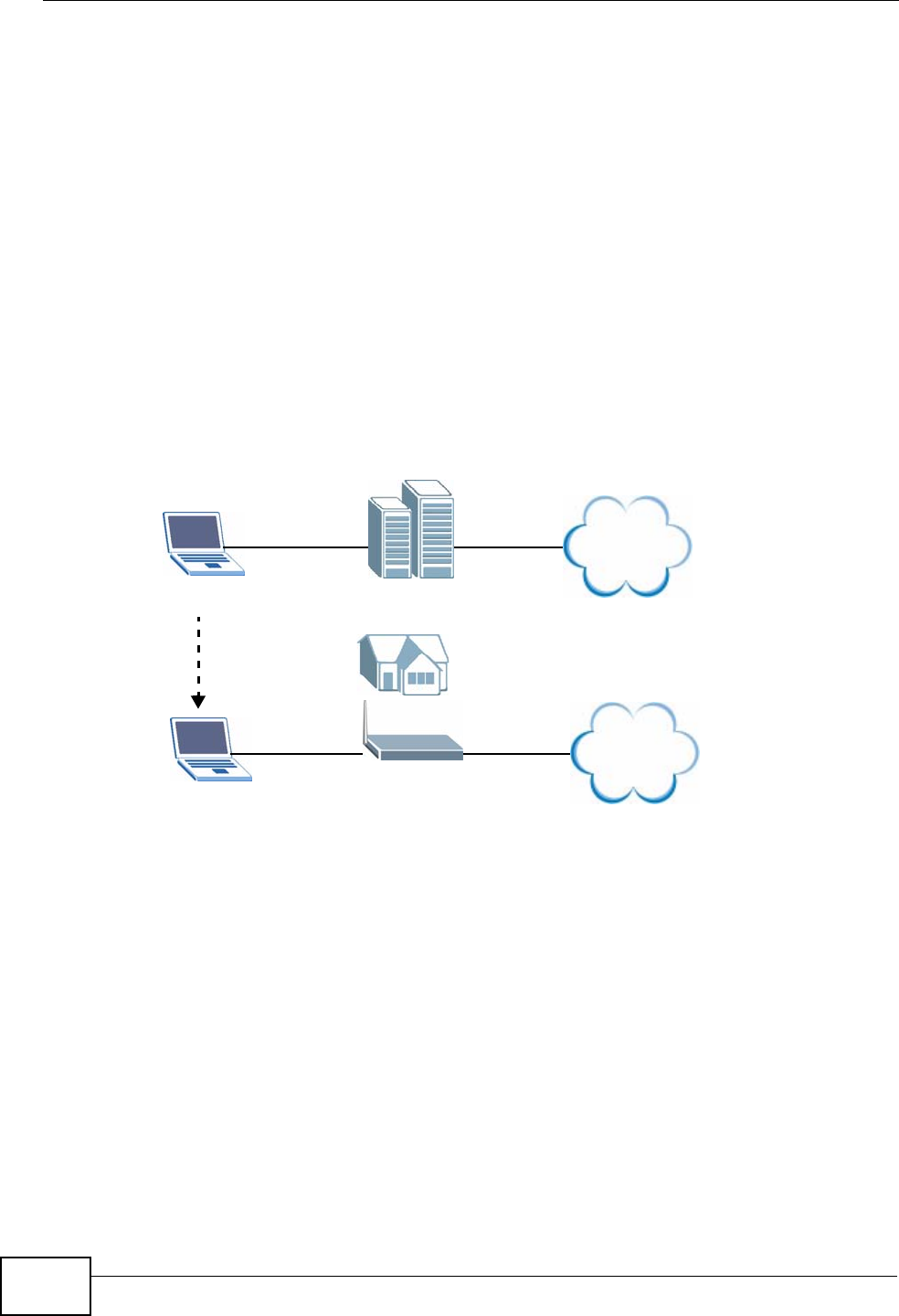
Chapter 7 LAN Setup
P-2612HWU-F1 User’s Guide
130
configure the network settings of the computer every time you want to access the
Internet via the ZyXEL Device.
With the Any IP feature and NAT enabled, the ZyXEL Device allows a computer to
access the Internet without changing the network settings (such as IP address and
subnet mask) of the computer, when the IP addresses of the computer and the
ZyXEL Device are not in the same subnet. Whether a computer is set to use a
dynamic or static (fixed) IP address, you can simply connect the computer to the
ZyXEL Device and access the Internet.
The following figure depicts a scenario where a computer is set to use a static
private IP address in the corporate environment. In a residential house where a
ZyXEL Device is installed, you can still use the computer to access the Internet
without changing the network settings, even when the IP addresses of the
computer and the ZyXEL Device are not in the same subnet.
Figure 88 Any IP Example
The Any IP feature does not apply to a computer using either a dynamic IP
address or a static IP address that is in the same subnet as the ZyXEL Device’s IP
address.
Note: You must enable NAT/SUA to use the Any IP feature on the ZyXEL Device.
How Any IP Works
Address Resolution Protocol (ARP) is a protocol for mapping an Internet Protocol
address (IP address) to a physical machine address, also known as a Media Access
Control or MAC address, on the local area network. IP routing table is defined on
IP Ethernet devices (the ZyXEL Device) to decide which hop to use, to help
forward data along to its specified destination.
Internet
192.168.1.1
192.168.10.1
Internet
192.168.10.1

Chapter 7 LAN Setup
P-2612HWU-F1 User’s Guide 131
The following lists out the steps taken, when a computer tries to access the
Internet for the first time through the ZyXEL Device.
1When a computer (which is in a different subnet) first attempts to access the
Internet, it sends packets to its default gateway (which is not the ZyXEL Device)
by looking at the MAC address in its ARP table.
2When the computer cannot locate the default gateway, an ARP request is
broadcast on the LAN.
3The ZyXEL Device receives the ARP request and replies to the computer with its
own MAC address.
4The computer updates the MAC address for the default gateway to the ARP table.
Once the ARP table is updated, the computer is able to access the Internet
through the ZyXEL Device.
5When the ZyXEL Device receives packets from the computer, it creates an entry in
the IP routing table so it can properly forward packets intended for the computer.
After all the routing information is updated, the computer can access the ZyXEL
Device and the Internet as if it is in the same subnet as the ZyXEL Device.

Chapter 7 LAN Setup
P-2612HWU-F1 User’s Guide
132
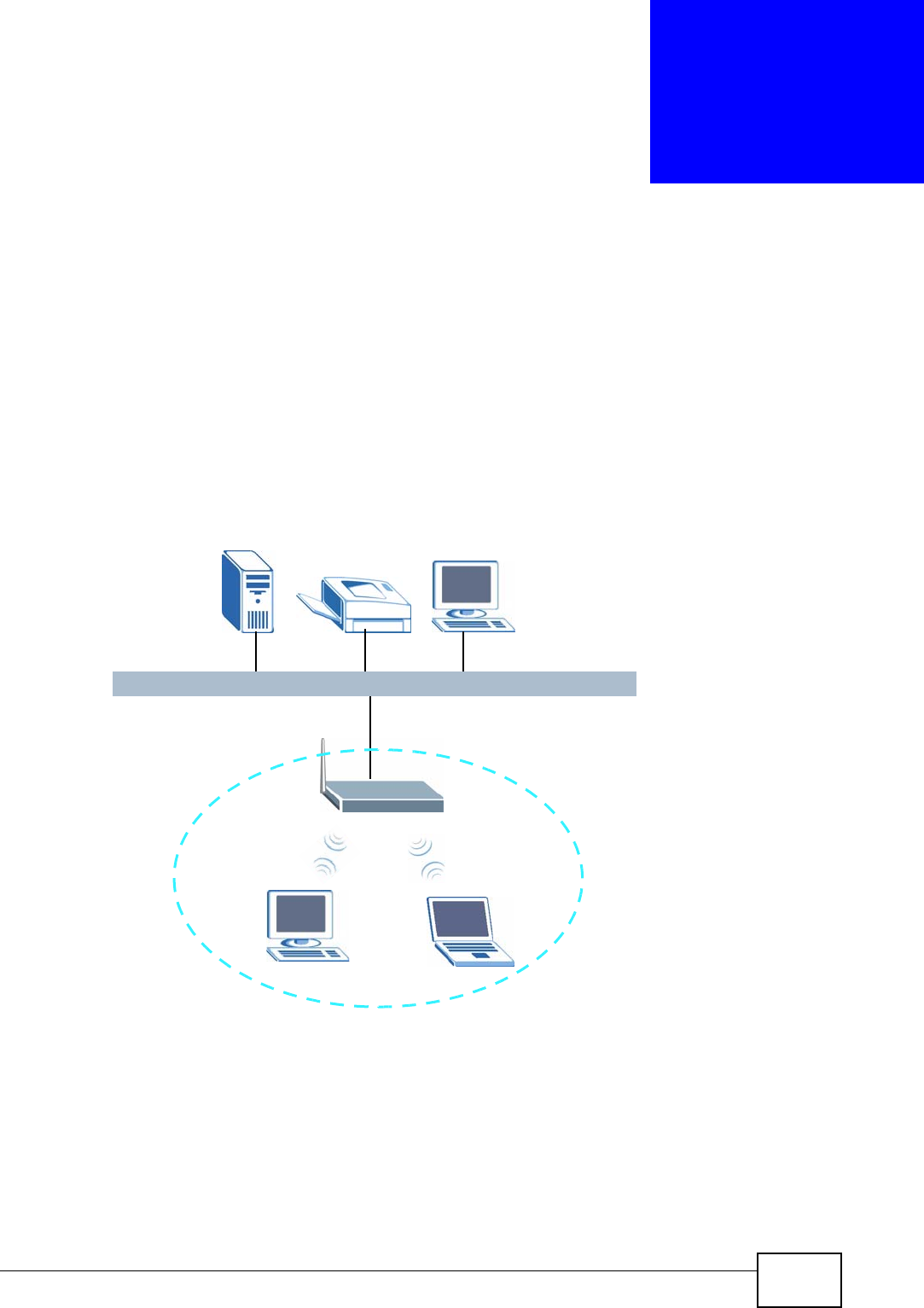
P-2612HWU-F1 User’s Guide 133
CHAPTER 8
Wireless LAN
8.1 Overview
The blue circle marks a wireless LAN in the following figure. Wireless clients (A and
B) connect to an access point (AP) to access other devices (such as the printer) or
the Internet. Your ZyXEL Device works as an AP when you install a compatible
WLAN card.
Figure 89 Example of a Wireless Network
8.1.1 What You Can Do in the Wireless LAN Screens
This chapter describes the ZyXEL Device’s Network > Wireless LAN screens.
Use these screens to set up your ZyXEL Device’s wireless connection.
AB
AP
Ethernet

Chapter 8 Wireless LAN
P-2612HWU-F1 User’s Guide
134
•Use the AP screen (see Section 8.2 on page 136) to turn the wireless
connection on or off, set up wireless security, configure the MAC filter, set up
Quality of Service and make other basic configuration changes.
•Use the Wireless LAN: Advanced Setup screen (see Section 8.2.5 on page
144) to change the wireless mode, and make other advanced wireless
configuration changes.
•Use the More AP screen (see Section 8.3 on page 145) to set up multiple
wireless networks on your ZyXEL Device.
•Use the MAC Filter screen (see Section 8.4 on page 147) to configure a MAC
(Media Access Control) address filter to restrict access to the wireless network.
•Use the WPS screen and the WPS Station screen to use WiFi Protected Setup
(WPS). WPS lets you set up a secure network quickly, when connecting to other
WPS-enabled devices.
Use the WPS screen (see Section 8.5 on page 148) to enable or disable WPS,
generate a security PIN (Personal Identification Number) and see information
about the ZyXEL Device’s WPS status.
Use the WPS Station (see Section 8.6 on page 149) screen to set up WPS by
pressing a button or using a PIN.
•Use the WDS screen (see Section 8.7 on page 150) to set up a Wireless
Distribution System, in which the ZyXEL Device acts as a bridge with other
ZyXEL access points.
•Use the Scheduling screen (see Section 8.8 on page 152) to schedule a time
period for the wireless LAN to operate each day.
You don’t necessarily need to use all these screens to set up your wireless
connection. For example, you may just want to set up a network name, a wireless
radio channel and some security in the AP screen.
8.1.2 What You Need to Know About Wireless
Wireless Basics
• Every device in the same wireless network must use the same Service Set
IDentity (SSID).
The SSID is the name of the wireless network.
• If two wireless networks overlap, they should use different channels.
Like radio stations or television channels, each wireless network uses a specific
channel, or frequency, to send and receive information.
Wireless Network Construction
Wireless networks consist of wireless clients, access points and bridges.
• A wireless client is a radio connected to a user’s computer.
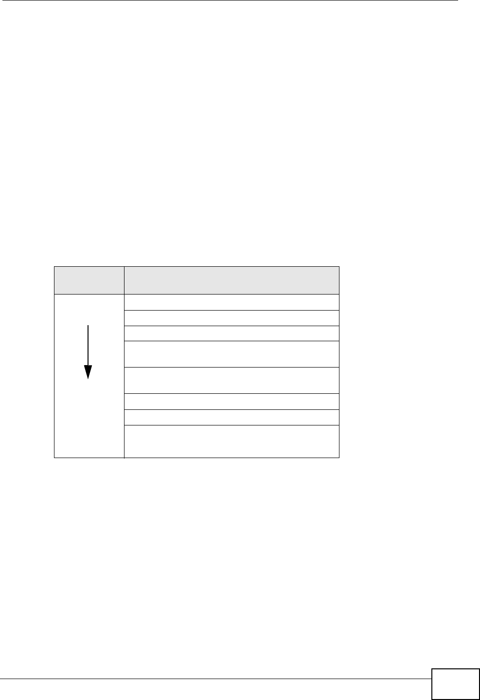
Chapter 8 Wireless LAN
P-2612HWU-F1 User’s Guide 135
• An access point is a radio with a wired connection to a network, which can
connect with numerous wireless clients and let them access the network.
• A bridge is a radio that relays communications between access points and
wireless clients, extending a network’s range.
Traditionally, a wireless network operates in one of two ways.
• An “infrastructure” type of network has one or more access points and one or
more wireless clients. The wireless clients connect to the access points.
• An “ad-hoc” type of network is one in which there is no access point. Wireless
clients connect to one another in order to exchange information.
Security
Security stops unauthorized devices from using the wireless network. It can also
protect the information that is sent in the wireless network.Use the strongest
security that every wireless client in the wireless network supports.
Note: WPA2 or WPA2-PSK security is recommended.
• WPA2-PSK and WPA-PSK do not employ user authentication and are known as
the personal version of WPA.
• WEP is better than no security, but it is still possible for unauthorized devices to
figure out the original information pretty quickly.
MAC Address Filter
Every Ethernet device has a unique MAC (Media Access Control) address. The MAC
address consists of twelve hexadecimal characters (0-9, and A to F), and it is
usually written in the following format: “0A:A0:00:BB:CC:DD”.
Table 26 Wireless Security Levels
SECURITY
LEVEL SECURITY TYPE
Weakest
Strongest
No Security
MAC Address Filtering
WEP Encryption
IEEE 802.1x EAP with RADIUS Server
Authentication
WPA-PSK (Wi-Fi Protected Access Pre-Shared
Key)
WPA (Wi-Fi Protected Access)
WPA-PSK2
WPA2

Chapter 8 Wireless LAN
P-2612HWU-F1 User’s Guide
136
The MAC address filter controls access to the wireless network. You can use the
MAC address of each wireless client to allow or deny access to the wireless
network.
Finding Out More
• See Chapter 4 on page 59 for a tutorial showing how to set up your wireless
connection in an example scenario.
• See Section 8.9 on page 153 for advanced technical information on wireless
networks.
8.1.3 Before You Start
Before you start using these screens, ask yourself the following questions. See
Section 8.1.2 on page 134 if some of the terms used here do not make sense to
you.
• What wireless standards do the other wireless devices support (IEEE 802.11g,
for example)? What is the most appropriate standard to use?
• What security options do the other wireless devices support (WPA-PSK, for
example)? What is the best one to use?
• Do the other wireless devices support WPS (Wi-Fi Protected Setup)? If so, you
can set up a well-secured network very easily.
Even if some of your devices support WPS and some do not, you can use WPS to
set up your network and then add the non-WPS devices manually, although this
is somewhat more complicated to do.
• What advanced options do you want to configure, if any? If you want to
configure advanced options such as Quality of Service, ensure that you know
precisely what you want to do. If you do not want to configure advanced
options, leave them alone.
8.2 AP Screen
Note: If you are configuring the ZyXEL Device from a computer connected to the
wireless LAN and you change the ZyXEL Device’s SSID or security settings,
you will lose your wireless connection when you press Apply to confirm. You
must then change the wireless settings of your computer to match the ZyXEL
Device’s new settings.
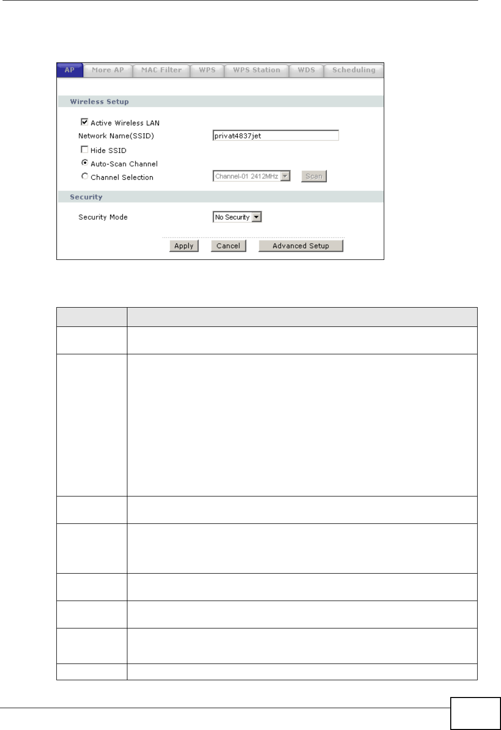
Chapter 8 Wireless LAN
P-2612HWU-F1 User’s Guide 137
Click Network > Wireless LAN to open the AP screen.
Figure 90 Network > Wireless LAN > AP
The following table describes the labels in this screen.
Table 27 Network > Wireless LAN > AP
LABEL DESCRIPTION
Active
Wireless LAN Click the check box to activate wireless LAN.
Network
Name (SSID) The SSID (Service Set IDentity) identifies the service set with which a
wireless device is associated. Wireless devices associating to the access
point (AP) must have the same SSID. Enter a descriptive name (up to 32
printable 7-bit ASCII characters) for the wireless LAN.
Note: If you are configuring the ZyXEL Device from a computer
connected to the wireless LAN and you change the ZyXEL
Device’s SSID or WEP settings, you will lose your wireless
connection when you press Apply to confirm. You must then
change the wireless settings of your computer to match the
ZyXEL Device’s new settings.
Hide SSID Select this check box to hide the SSID in the outgoing beacon frame so a
station cannot obtain the SSID through scanning using a site survey tool.
Auto-Scan
Channel Select this option and click Apply to have the ZyXEL Device scan for and
select a channel which is not used by another device. The ZyXEL Device
automatically scans for and selects a channel whenever the device reboots
or the wireless setting is changed.
Channel
Selection Select this option and set the operating frequency/channel depending on
your particular region. Select a channel from the drop-down list box.
Scan Click this button to have the ZyXEL Device immediately scan for and select
a channel which is not used by another device.
Security
Mode See the following sections for more details about this field.
Static WEP, WPA and WPA2 are available only when WPS is disabled.
Apply Click Apply to save your changes back to the ZyXEL Device.
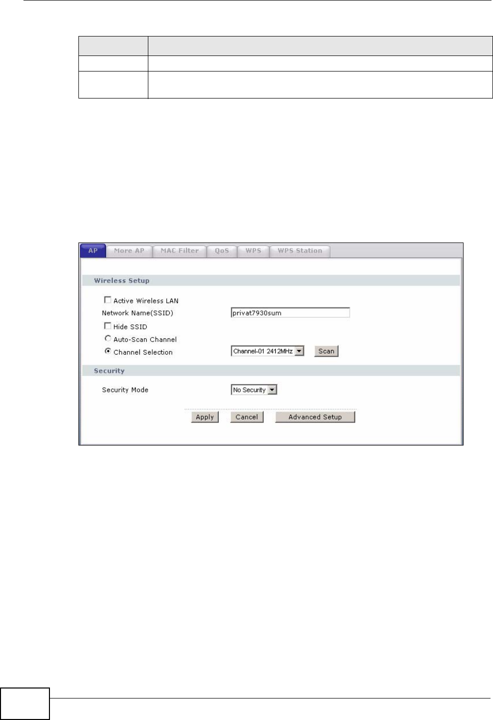
Chapter 8 Wireless LAN
P-2612HWU-F1 User’s Guide
138
8.2.1 No Security
Select No Security to allow wireless devices to communicate with the access
points without any data encryption.
Note: If you do not enable any wireless security on your ZyXEL Device, your network
is accessible to any wireless networking device that is within range.
Figure 91 Network > Wireless LAN > AP: No Security
Cancel Click Cancel to reload the previous configuration for this screen.
Advanced
Setup Click Advanced Setup to display the Wireless Advanced Setup screen
and edit more details of your WLAN setup.
Table 27 Network > Wireless LAN > AP (continued)
LABEL DESCRIPTION
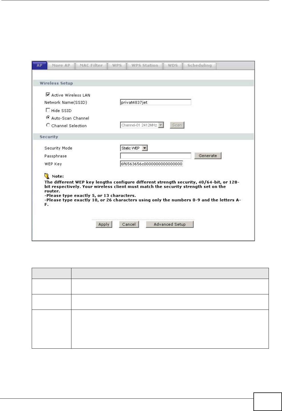
Chapter 8 Wireless LAN
P-2612HWU-F1 User’s Guide 139
8.2.2 WEP Encryption
In order to configure and enable WEP encryption; click Network > Wireless LAN
to display the AP screen. Select Static WEP from the Security Mode list.
Figure 92 Network > Wireless LAN > AP: Static WEP Encryption
The following table describes the wireless LAN security labels in this screen.
Table 28 Network > Wireless LAN > AP: Static WEP Encryption
LABEL DESCRIPTION
Security
Mode Choose Static WEP from the drop-down list box.
Passphrase Enter a passphrase (up to 32 printable characters) and clicking Generate.
The ZyXEL Device automatically generates a WEP key.
WEP Key The WEP key is used to encrypt data. Both the ZyXEL Device and the
wireless stations must use the same WEP key for data transmission.
If you want to manually set the WEP key, enter any 5 or 13 characters
(ASCII string) or 10 or 26 hexadecimal characters ("0-9", "A-F") for a 64-
bit or 128-bit WEP key respectively.
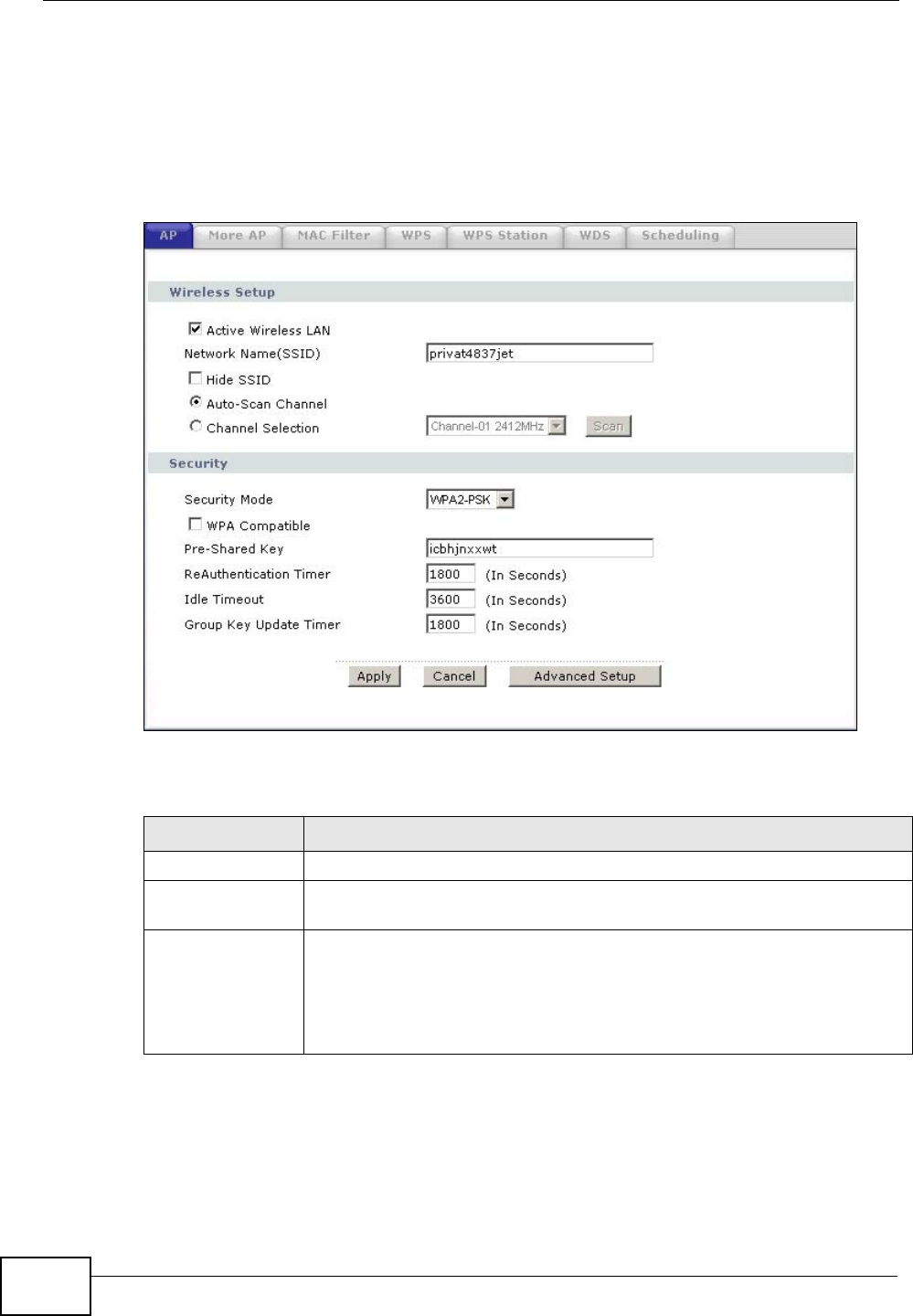
Chapter 8 Wireless LAN
P-2612HWU-F1 User’s Guide
140
8.2.3 WPA(2)-PSK
In order to configure and enable WPA(2)-PSK authentication; click Network >
Wireless LAN to display the AP screen. Select WPA-PSK or WPA2-PSK from
the Security Mode list.
Figure 93 Network > Wireless LAN > AP: WPA(2)-PSK
The following table describes the wireless LAN security labels in this screen.
Table 29 Network > Wireless LAN > AP: WPA(2)-PSK
LABEL DESCRIPTION
Security Mode Choose WPA-PSK or WPA2-PSK from the drop-down list box.
WPA Compatible This field is only available for WPA2-PSK. Select this if you want the
ZyXEL Device to support WPA-PSK and WPA2-PSK simultaneously.
Pre-Shared Key The encryption mechanisms used for WPA(2) and WPA(2)-PSK are
the same. The only difference between the two is that WPA(2)-PSK
uses a simple common password, instead of user-specific credentials.
Type a pre-shared key from 8 to 63 case-sensitive ASCII characters
(including spaces and symbols).

Chapter 8 Wireless LAN
P-2612HWU-F1 User’s Guide 141
ReAuthentication
Timer (in
seconds)
Specify how often wireless stations have to resend usernames and
passwords in order to stay connected. Enter a time interval between 10
and 9999 seconds. The default time interval is 1800 seconds (30
minutes).
Note: If wireless station authentication is done using a RADIUS
server, the reauthentication timer on the RADIUS server has
priority.
Idle Timeout The ZyXEL Device automatically disconnects a wireless station from the
wired network after a period of inactivity. The wireless station needs to
enter the username and password again before access to the wired
network is allowed. The default time interval is 3600 seconds (or 1
hour).
Group Key
Update Timer The Group Key Update Timer is the rate at which the AP (if using
WPA(2)-PSK key management) or RADIUS server (if using
WPAWPA(2) key management) sends a new group key out to all clients.
The re-keying process is the WPA(2) equivalent of automatically
changing the WEP key for an AP and all stations in a WLAN on a periodic
basis. Setting of the Group Key Update Timer is also supported in
WPA(2)-PSK mode. The ZyXEL Device default is 1800 seconds (30
minutes).
Table 29 Network > Wireless LAN > AP: WPA(2)-PSK
LABEL DESCRIPTION
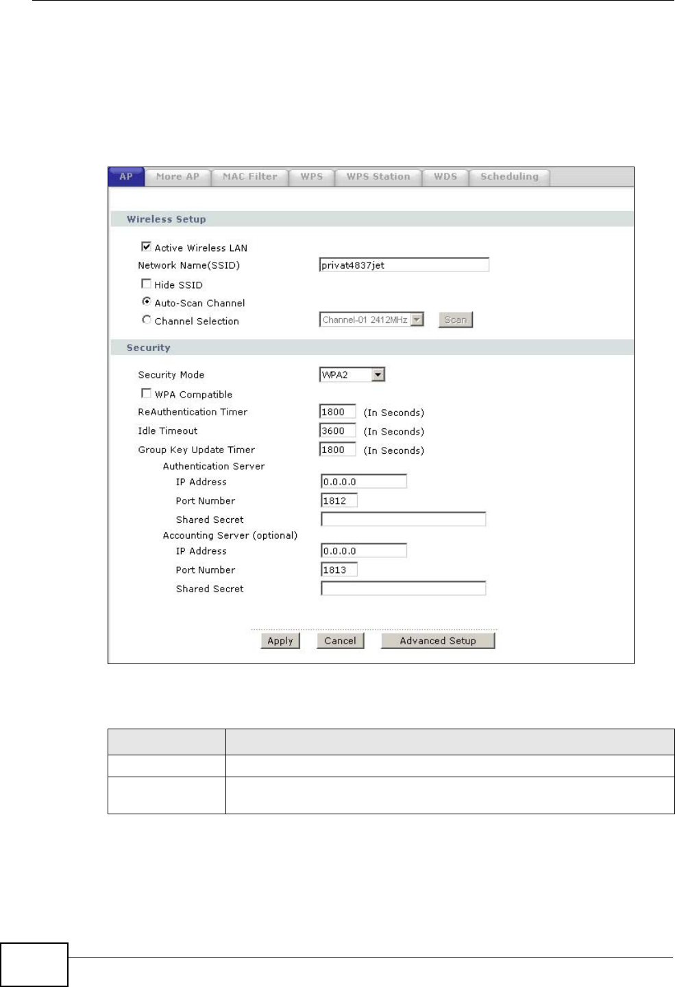
Chapter 8 Wireless LAN
P-2612HWU-F1 User’s Guide
142
8.2.4 WPA(2) Authentication Screen
In order to configure and enable WPA authentication; click the Wireless LAN link
under Network to display the AP screen. Select WPA or WPA2 from the
Security Mode list.
Figure 94 Network > Wireless LAN > AP: WPA(2)
The following table describes the wireless LAN security labels in this screen.
Table 30 Network > Wireless LAN > AP: WPA(2)
LABEL DESCRIPTION
Security Mode Choose WPA or WPA2 from the drop-down list box.
WPA Compatible This field is only available for WPA2. Select this if you want the ZyXEL
Device to support WPA and WPA2 simultaneously.

Chapter 8 Wireless LAN
P-2612HWU-F1 User’s Guide 143
ReAuthentication
Timer (in
seconds)
Specify how often wireless stations have to resend usernames and
passwords in order to stay connected. Enter a time interval between
10 and 9999 seconds. The default time interval is 1800 seconds (30
minutes).
Note: If wireless station authentication is done using a RADIUS
server, the reauthentication timer on the RADIUS server has
priority.
Idle Timeout The ZyXEL Device automatically disconnects a wireless station from
the wired network after a period of inactivity. The wireless station
needs to enter the username and password again before access to the
wired network is allowed. The default time interval is 3600 seconds (or
1 hour).
Group Key
Update Timer The Group Key Update Timer is the rate at which the AP (if using
WPA(2)-PSK key management) or RADIUS server (if using WPA(2)
key management) sends a new group key out to all clients. The re-
keying process is the WPA(2) equivalent of automatically changing the
WEP key for an AP and all stations in a WLAN on a periodic basis.
Setting of the Group Key Update Timer is also supported in
WPA(2)-PSK mode. The ZyXEL Device default is 1800 seconds (30
minutes).
Authentication Server
IP Address Enter the IP address of the external authentication server in dotted
decimal notation.
Port Number Enter the port number of the external authentication server. The
default port number is 1812.
You need not change this value unless your network administrator
instructs you to do so with additional information.
Shared Secret Enter a password (up to 31 alphanumeric characters) as the key to be
shared between the external authentication server and the ZyXEL
Device.
The key must be the same on the external authentication server and
your ZyXEL Device. The key is not sent over the network.
Accounting Server (optional)
IP Address Enter the IP address of the external accounting server in dotted
decimal notation.
Port Number Enter the port number of the external accounting server. The default
port number is 1813.
You need not change this value unless your network administrator
instructs you to do so with additional information.
Shared Secret Enter a password (up to 31 alphanumeric characters) as the key to be
shared between the external accounting server and the ZyXEL Device.
The key must be the same on the external accounting server and your
ZyXEL Device. The key is not sent over the network.
Table 30 Network > Wireless LAN > AP: WPA(2)
LABEL DESCRIPTION
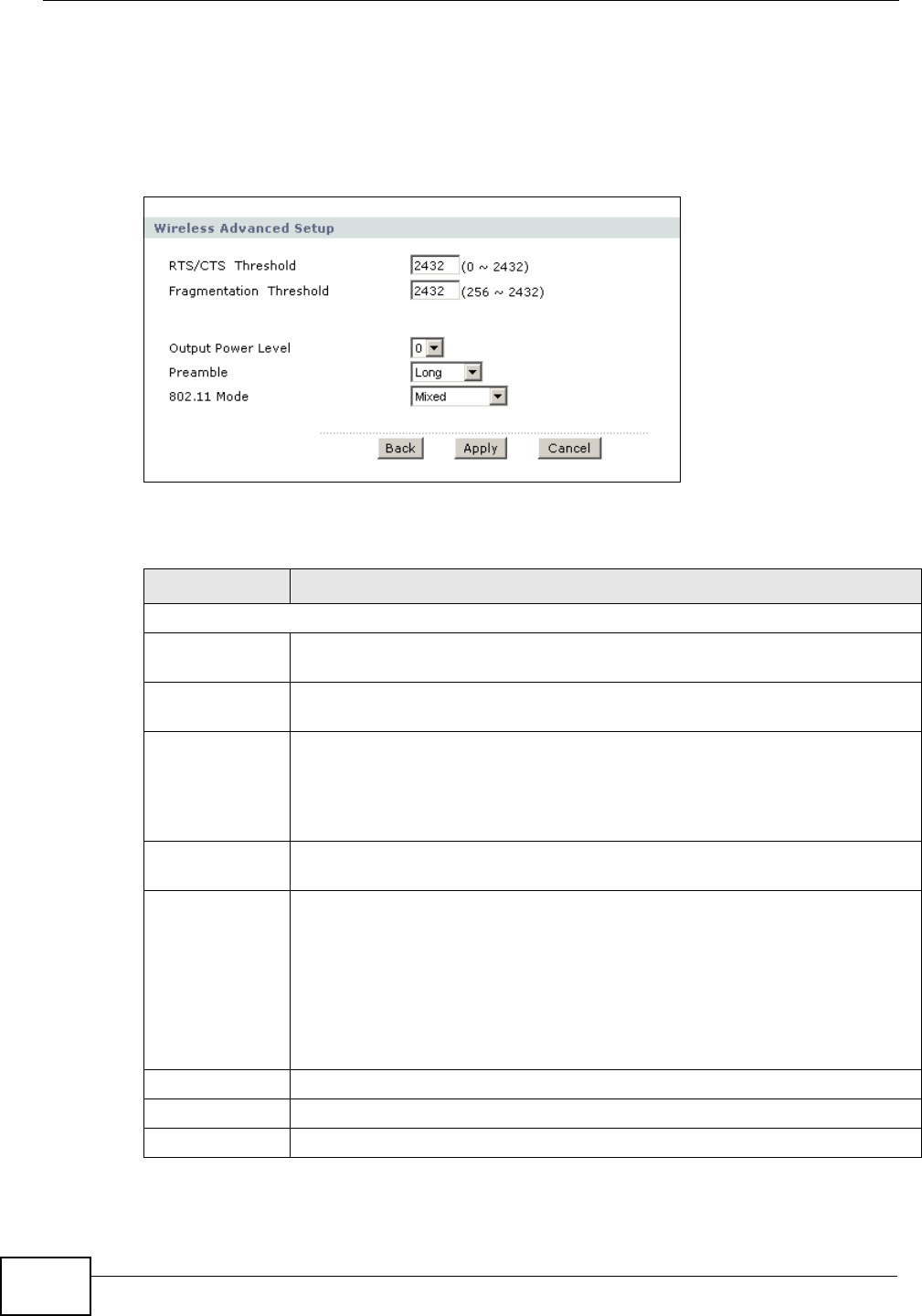
Chapter 8 Wireless LAN
P-2612HWU-F1 User’s Guide
144
8.2.5 Wireless LAN Advanced Setup
To configure advanced wireless settings, click the Advanced Setup button in the
AP screen. The screen appears as shown.
Figure 95 Network > Wireless LAN > AP > Advanced Setup
The following table describes the labels in this screen.
Table 31 Network > Wireless LAN > AP > Advanced Setup
LABEL DESCRIPTION
Wireless Advanced Setup
RTS/CTS
Threshold Enter a value between 0 and 2432.
Fragmentation
Threshold It is the maximum data fragment size that can be sent. Enter a value
between 256 and 2432.
Output Power
Level Set the output power of the ZyXEL Device in this field. The higher the
number, the greater the output power. If there is a high density of APs in
the area, decrease the output power of the ZyXEL Device to reduce
interference with other APs. See the product specifications for more
information on your ZyXEL Device’s output power.
Preamble Select a preamble type. Choices are Long, Short or Dynamic. The
default setting is Long. See the appendix for more information.
802.11 Mode Select 802.11b Only to allow only IEEE 802.11b compliant WLAN devices
to associate with the ZyXEL Device.
Select 802.11g Only to allow only IEEE 802.11g compliant WLAN devices
to associate with the ZyXEL Device.
Select Mixed to allow either IEEE 802.11b or IEEE 802.11g compliant
WLAN devices to associate with the ZyXEL Device. The transmission rate
of your ZyXEL Device might be reduced.
Back Click this to return to the previous screen without saving changes.
Apply Click Apply to save your changes back to the ZyXEL Device.
Cancel Click Cancel to reload the previous configuration for this screen.
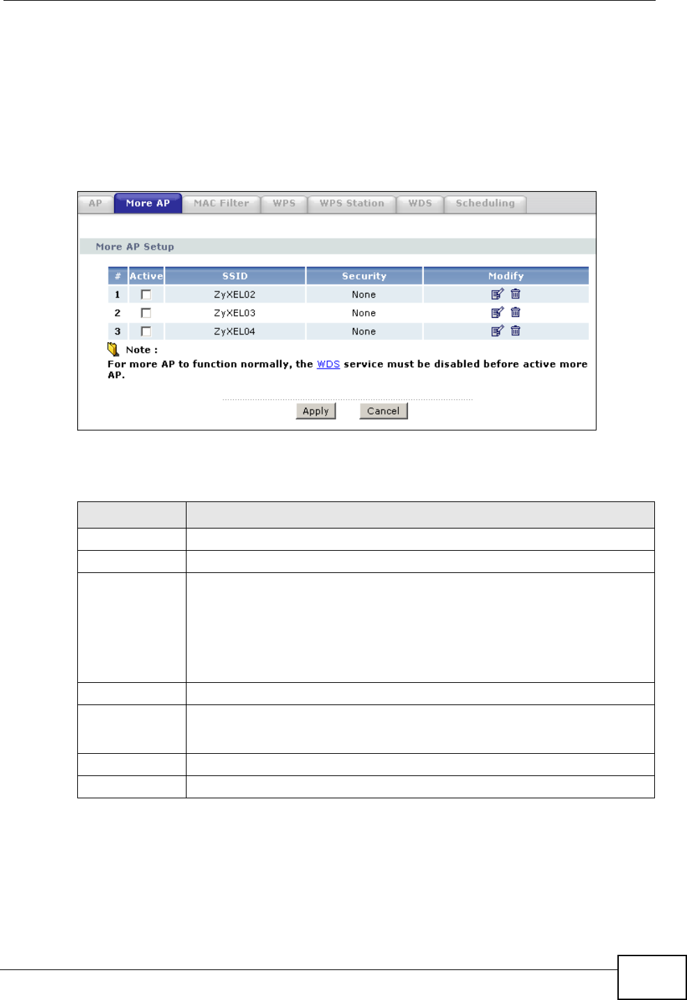
Chapter 8 Wireless LAN
P-2612HWU-F1 User’s Guide 145
8.3 More AP Screen
This screen allows you to enable and configure multiple BSSs on the ZyXEL
Device.
Click Network > Wireless LAN > More AP. The following screen displays.
Figure 96 Network > Wireless LAN > More AP
The following table describes the labels in this screen.
Table 32 Network > Wireless LAN > More AP
LABEL DESCRIPTION
# This is the index number of each SSID profile.
Active Select the check box to activate an SSID profile.
SSID An SSID profile is the set of parameters relating to one of the ZyXEL
Device’s BSSs. The SSID (Service Set IDentifier) identifies the Service
Set with which a wireless device is associated.
This field displays the name of the wireless profile on the network. When
a wireless client scans for an AP to associate with, this is the name that
is broadcast and seen in the wireless client utility.
Security This field indicates the security mode of the SSID profile.
Modify Click the Edit icon to configure the SSID profile.
Click the Remove icon to delete the SSID profile.
Apply Click Apply to save your changes back to the ZyXEL Device.
Cancel Click Cancel to reload the previous configuration for this screen.
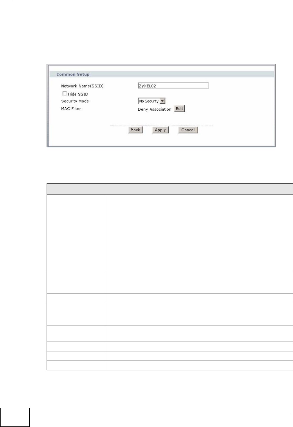
Chapter 8 Wireless LAN
P-2612HWU-F1 User’s Guide
146
8.3.1 More AP Edit
Use this screen to edit an SSID profile. Click the Edit icon next to an SSID in the
More AP screen. The following screen displays.
Figure 97 Network > Wireless LAN > More AP > Edit
See Appendix E on page 557 for a list of commonly-used services and destination
ports. The following table describes the fields in this screen.
Table 33 Network > Wireless LAN > More AP > Edit
LABEL DESCRIPTION
Network Name
(SSID) The SSID (Service Set IDentity) identifies the service set with which
a wireless device is associated. Enter a descriptive name (up to 32
printable 7-bit ASCII characters) for the wireless LAN.
Note: If you are configuring the ZyXEL Device from a computer
connected to the wireless LAN and you change the
ZyXEL Device’s SSID or security settings, you will lose
your wireless connection when you press Apply to
confirm. You must then change the wireless settings of
your computer to match the ZyXEL Device’s new settings.
Hide SSID Select this check box to hide the SSID in the outgoing beacon frame
so a station cannot obtain the SSID through scanning using a site
survey tool.
Security Mode See Section 8.2 on page 136 for more details about this field.
MAC Filter This shows whether the wireless devices with the MAC addresses
listed are allowed or denied to access the ZyXEL Device using this
SSID.
Edit Click this button to go to the MAC Filter screen to configure MAC
filter settings. See Section 8.4 on page 147 for more details.
Back Click this to return to the previous screen without saving changes.
Apply Click Apply to save your changes back to the ZyXEL Device.
Cancel Click Cancel to reload the previous configuration for this screen.
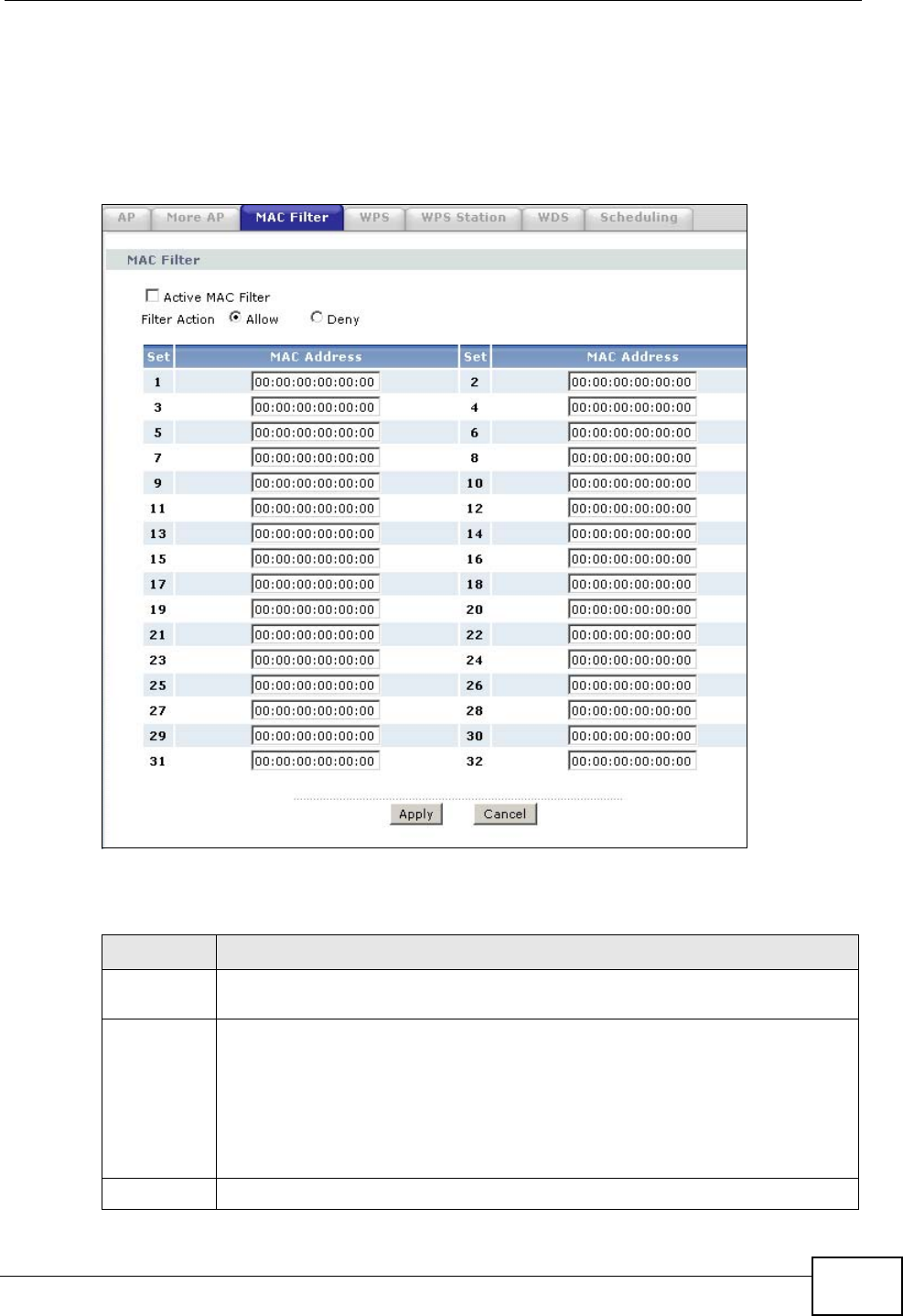
Chapter 8 Wireless LAN
P-2612HWU-F1 User’s Guide 147
8.4 MAC Filter
Use this screen to change your ZyXEL Device’s MAC filter settings. Click Network
> Wireless LAN > MAC Filter. The screen appears as shown.
Figure 98 Network > Wireless LAN > MAC Filter
The following table describes the labels in this screen.
Table 34 Network > Wireless LAN > MAC Filter
LABEL DESCRIPTION
Active MAC
Filter Select the check box to enable MAC address filtering.
Filter Action Define the filter action for the list of MAC addresses in the MAC Address
table.
Select Deny to block access to the ZyXEL Device, MAC addresses not listed
will be allowed to access the ZyXEL Device
Select Allow to permit access to the ZyXEL Device, MAC addresses not
listed will be denied access to the ZyXEL Device.
Set This is the index number of the MAC address.
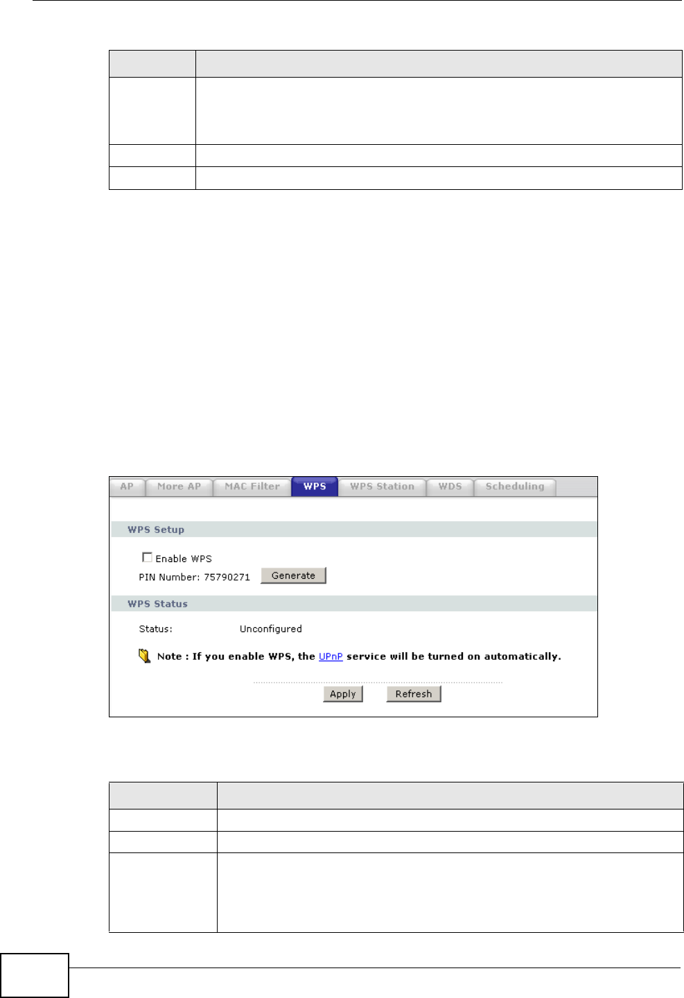
Chapter 8 Wireless LAN
P-2612HWU-F1 User’s Guide
148
8.5 WPS
Use this screen to configure WiFi Protected Setup (WPS) on your ZyXEL Device.
WPS allows you to quickly set up a wireless network with strong security, without
having to configure security settings manually. Set up each WPS connection
between two devices. Both devices must support WPS. See Appendix D on page
533 for more information about WPS.
Click Network > Wireless LAN >WPS. The following screen displays.
Figure 99 Network > Wireless LAN > WPS
The following table describes the labels in this screen.
MAC
Address Enter the MAC addresses of the wireless devices that are allowed or denied
access to the ZyXEL Device in these address fields. Enter the MAC
addresses in a valid MAC address format, that is, six hexadecimal character
pairs, for example, 12:34:56:78:9a:bc.
Apply Click Apply to save your changes back to the ZyXEL Device.
Cancel Click Cancel to reload the previous configuration for this screen.
Table 34 Network > Wireless LAN > MAC Filter
LABEL DESCRIPTION
Table 35 Network > Wireless LAN > WPS
LABEL DESCRIPTION
WPS Setup
Enable WPS Select the check box to activate WPS on the ZyXEL Device.
PIN Number This shows the PIN (Personal Identification Number) of the ZyXEL
Device. Enter this PIN in the configuration utility of the device you want
to connect to using WPS.
The PIN is not necessary when you use WPS push-button method.
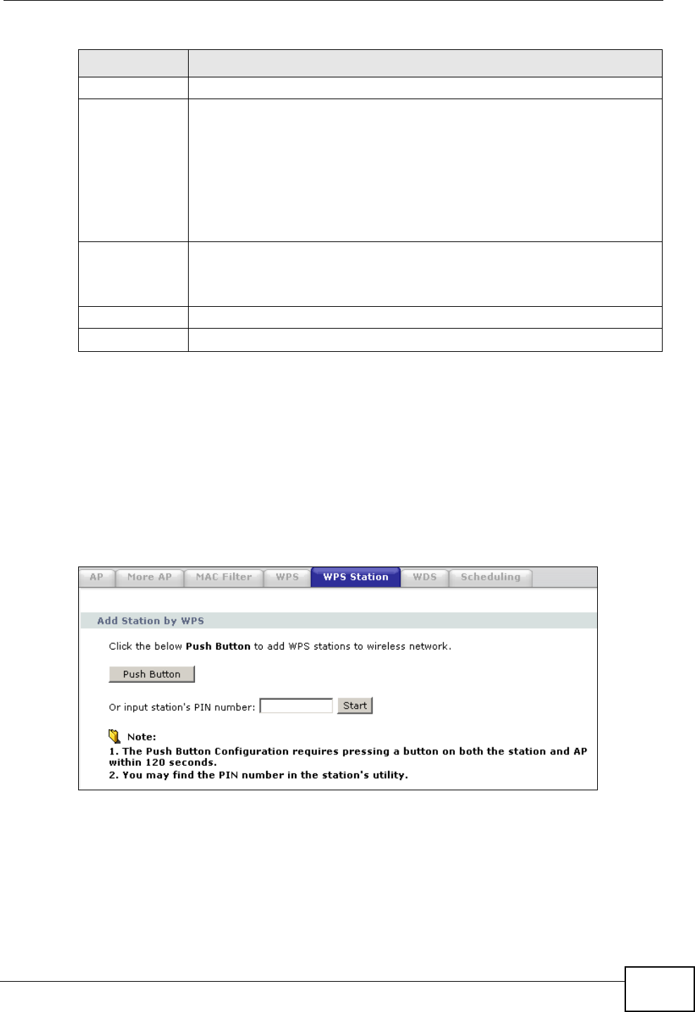
Chapter 8 Wireless LAN
P-2612HWU-F1 User’s Guide 149
8.6 WPS Station
Use this screen to set up a WPS wireless network using either Push Button
Configuration (PBC) or PIN Configuration.
Click Network > Wireless LAN >WPS Station. The following screen displays.
Figure 100 Network > Wireless LAN > WPS Station
Generate Click this button to have the ZyXEL Device create a new PIN.
WPS Status This displays Configured when the ZyXEL Device has connected to a
wireless network using WPS or Enable WPS is selected and wireless or
wireless security settings have been changed. The current wireless and
wireless security settings also appear in the screen.
This displays Unconfigured if WPS is disabled and there is no wireless
or wireless security changes on the ZyXEL Device or you click
Release_Configuration to remove the configured wireless and
wireless security settings.
Release_Co
nfiguration This button is available when the WPS status is Configured.
Click this button to remove all configured wireless and wireless security
settings for WPS connections on the ZyXEL Device.
Apply Click Apply to save your changes back to the ZyXEL Device.
Refresh Click Refresh to reload the previous configuration for this screen.
Table 35 Network > Wireless LAN > WPS
LABEL DESCRIPTION

Chapter 8 Wireless LAN
P-2612HWU-F1 User’s Guide
150
The following table describes the labels in this screen.
8.7 WDS Screen
Use this screen to set up your WDS (Wireless Distribution System) links between
the ZyXEL Device and other wireless APs. You need to know the MAC address of
the peer device. Once the security settings of peer sides match one another, the
connection between devices is made.
Note: WDS security is independent of the security settings between the ZyXEL
Device and any wireless clients.
At the time of writing, WDS is compatible with some ZyXEL Devices only. Not all
models support WDS links. Check your other ZyXEL Device’s documentation.
Table 36 Network > Wireless LAN > WPS Station
LABEL DESCRIPTION
Push Button Click this button to add another WPS-enabled wireless device (within
wireless range of the ZyXEL Device) to your wireless network. This
button may either be a physical button on the outside of device, or a
menu button similar to the Push Button on this screen.
Note: You must press the other wireless device’s WPS button within
two minutes of pressing this button.
Or input
station's PIN
number
Enter the PIN of the device that you are setting up a WPS connection
with and click Start to authenticate and add the wireless device to your
wireless network.
You can find the PIN either on the outside of the device, or by checking
the device’s settings.
Note: You must also activate WPS on that device within two minutes
to have it present its PIN to the ZyXEL Device.