dormakaba USA SDC2K Wireless Electronic Lock User Manual Manual 1
Stanley Security Solutions, Inc. Wireless Electronic Lock Manual 1
Contents
Manual 1

Copyright ©2012 Stanley Security Solutions, Inc.
All rights reserved.
Information in this document is subject to change without notice and does not represent
a commitment on the part of Stanley Security Solutions, Inc. The software described in
this document are furnished under a license agreement or nondisclosure agreement.
This publication is intended to be an accurate description and set of instructions
pertaining to its subject matter. However, as with any publication of this complexity,
errors or omissions are possible. Please call Stanley Security Solutions, Inc. at (317)
849-2250 if you see any errors or have any questions. No part of this manual and/or
databases may be reproduced or transmitted in any form or by any means, electronic
or mechanical, including photocopying, recording, or information storage and retrieval
systems, for any purpose, without the express written permission of Stanley Security
Solutions, Inc.
This document is distributed as is, without warranty of any kind, either express or
implied, respecting the contents of this book, including but not limited to implied
warranties for the publication’s quality, performance, merchantability, or fitness for any
particular purpose. Neither Stanley Security Solutions, Inc, nor its dealers or distributors
shall be liable to the user or any other person or entity with respect to any liability, loss,
or damage caused or alleged to be caused directly or indirectly by this publication.
The Stanley Wi-Q AMS and Wi-Q Technology are registered trademarks of Stanley
Security Solutions, Inc.
Bonjour is a registered trademark of Apple Inc.
Wi-Spy and MetaGeek are registered trademarks of MetaGeek, LLC.
Microsoft, Windows, CE, and ActiveSync are registered trademarks of Microsoft
Corporation.
T85202/Rev D June 2015
FCC/IC Certification
CAUTION: Please keep the PG antenna 20cm away from people to ensure that FCC RF
exposure compliance requirements are not exceeded.
This equipment has been tested and found to comply with the limits for Class B Digital
Device, pursuant to Part 15 of the FCC Rules. These limits are designed to provide
reasonable protection against harmful interference in a residential installation. This
equipment generates and can radiate radio frequency energy and, if not installed and
used in accordance with the instructions, may cause harmful interference to radio
communications. However, there is no guarantee that interference will not occur in a
particular installation. If this equipment does cause harmful interference to radio or
television reception, which can be determined by turning the equipment off and on, you
can try to correct the interference by taking one or more of the following measures.
Reorient or relocate the receiving antenna
Increase the separation between the equipment and receiver
Connect the equipment into an outlet on a circuit different from that to which the
receiver is connected
Consult the dealer or an experienced radio/TV technician for help.
This device complies with Industry Canada licence-exempt RSS standard(s). Operation is
subject to the following two conditions: (1) This device may not cause interference, and
(2) this device must accept any interference, including any interference that may cause
undesired operation of the device.
Cet appareil est conforme à la norme RSS Industrie Canada exempt de licence. Son
fonctionnement est soumis aux deux conditions suivantes: (1) cet appareil ne doit pas
provoquer d’interférences et (2) cet appareil doit accepter toute interférence, y compris
les interferences pouvant causer un mauvais fonctionnement du dispositif.
This Class [B] digital apparatus meets all requirements of the Canadian Interference-
Causing Equipment Regulations.
Cet appareil numérique de la classe [B] respecte toutes les exigences du Réglement sur
le matériel brouilleur du Canada.
Warning! Changes or modifications not expressly approved by {Applicant name} could
void the user’s authority to operate the equipment. Approved antennas are listed below
and antennas not included in this list are strictly prohibited for use with these devices.
The required antenna impedance is 50 ohms.
Approved Antennas
Portal Gateway/WAC
HG2402RD-RSF - 2.4GHz Rubber Duck Antenna
MP24008XFPTNF - 2.4GHz ISM-XF Panel Antenna
MC2400PTMSMA - 2.4GHz Omni-Directional Antenna
BS2400XL3 - 2.4GHz Outdoor Omni-Directional Antenna
Controller
Integrated Antenna
IMPORTANT! Any changes or modifications not expressly approved by the party
responsible for compliance could void the user’s authority to operate the equipment.
Contents
1 Overview
System Overview ............................................................. 7
Setup Checklist .............................................................. 12
2 Hardware Installation
Hardware Overview ...................................................... 13
Installing System Hardware ........................................ 16
Install Portal Gateways (Task 8)................................. 24
Install Door Hardware (Task 9) ................................... 28
3 Software Installation
Prepare Your Computer (Task 3) .................................33
Gather and Organize Segment Data
(Task 4) .............................................................................43
Install Software (Task 5) .............................................. 45
4 Configuring Segments, Portal Gateways
and Controllers
Create Your Segment (Task 6) ..................................... 63
Add and Configure Portal Gateways
(Task 7) .............................................................................67
Sign on and Configure Controllers
(Task 10) ...........................................................................84
5 Configure AMS Software
(Task 11)
Associations ................................................................... 96
Credential Settings ...................................................... 108
Daylight Saving Settings ............................................ 116
I/O ................................................................................... 116
Misc ................................................................................ 120
PIN Settings ..................................................................120
Adding Users to the Segment .................................... 121
Portal and Reader Control and
Messaging ..................................................................... 134
Configuring Timezones ............................................... 137
6 Using and Managing the System
Wi-Q AMS
Configurator ..................................................................145
System Administrator ................................................. 166
Backing Up and Restoring Your
AMS Database.............................................................. 174
Firmware Updates ....................................................... 178
Transactions Monitor .................................................. 181
Statistics Monitor ........................................................ 191
Reports ...........................................................................199
7 Advanced Troubleshooting
Status Flags in the FLAGS Column ........................... 211
Update Flags in the PEND Column ........................... 212
A Glossary .................................................214
B Lock installation ...................................220
7
This manual is your complete guide to the Stanley Wi-Q Access Management
System. It provides detailed steps to install hardware and software, configure and
customize your system, and use and manage the system.
The information is presented in a linear manner, describing each tab, feature and
application in the system. However, tasks to install hardware and software and
configure the system for the first time do not necessarily progress in a linear man-
ner. You will find a Set Up Checklist at the end of this section and in the Getting
Started Guide to take you through the initial setup and configuration tasks in a
logical sequence.
If you have not yet read through the Wi-Q AMS Getting Started Guide, it is a good
idea to do so before beginning any installation and setup. The Getting Started
Guide presents the big picture in just a few pages and will help you identify prob-
lems and create solutions as you work your way through hardware installation
and setup, software configuration, and system operation. If you are unfamiliar
with the terms used in wireless technology, you may want to refer to the Glossary
included in this manual as Appendix A.
System Overview
The Stanley Wi-Q Access Management System (Wi-Q AMS) integrates pow-
erful access management software with Portal Gateways, Wireless Access
1 Overview
8
Controllers, and multiple controller formats that work together to enable all deci-
sion-making at the door. The system runs remotely with no need for hard-wiring,
providing innovative access control in any environment. Wi-Q AMS is versatile so
you can create a whole new system, retrofit existing hardware, and include vari-
ous CCTV alarms, general alarms, and inputs/outputs.
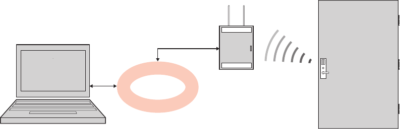
Basic Hardware Components
A basic Wi-Q AMS system has three components: a host computer with Wi-Q
AMS, a Portal Gateway, and a controller lock at the door. Figure 1 is a simple dia-
gram showing these three components.
Figure 1 Four Basic Components
The Host Computer
The software is installed at the Host computer and set up to tell the Portal Gate-
ways on the network which controllers to control and how to control them. It
contains all User ID and access management commands. The Host transfers
information to and from the Portal Gateway through a standard Ethernet (LAN/
WAN) connection.
The Portal Gateway
The Portal Gateway is a device connected to the Host computer through a secure
IP address, similar to the way your computer is connected to the internet. It trans-
fers data signals from Wireless Controllers to and from the Host computer. The
Portal Gateway recognizes all Wireless Controllers within its antenna range. One
Portal Gateway can control as many as 64 controllers in a system.
Wireless Controllers
There are two types of Wi-Q and Omnilock Wireless Controllers:
HOST
LAN/WAN
PORTAL
GATEWAY
WIRELESS
DOOR
CONTROLLER
9
Wi-Q
Wireless Access Controller
Wireless Door Controller
Omnilock
Single Door Controller
Omnilock Reader
Both controllers are equipped with Wi-Q or Omnilock Technology that controls
user access at the door. The basic configuration is battery operated, with either
keypad or card reading capability and an internal antenna that communicates with
the Portal Gateway. The Wireless Controller grants user requests according to
how they are configured in the AMS software.
Basic Operation
The system works very simply. A user enters a pass code at a controller, either
using an access card or by entering a code on a keypad. If the controller recog-
nizes the credential from the configured settings downloaded from the Host via
the Portal Gateway to the controller, the door opens. The controller also sends
regular signals (beacons) to the Portal to let it know that it’s working properly. If a
controller goes offline, the Host receives a message from the Portal Gateway.
10
Additional System Configurations
Wi-Q AMS supports various system configurations. For example, some locations
at your segment may already be hard-wired with legacy equipment or additional
input or output devices. You can also use a Wireless Access Controller, hard-
wired to a controller and strike, and wirelessly communicate back to a Portal
Gateway.
For more information about various applications you can adapt for use with Wi-Q
AMS, see “Hardware Overview” on page 13.
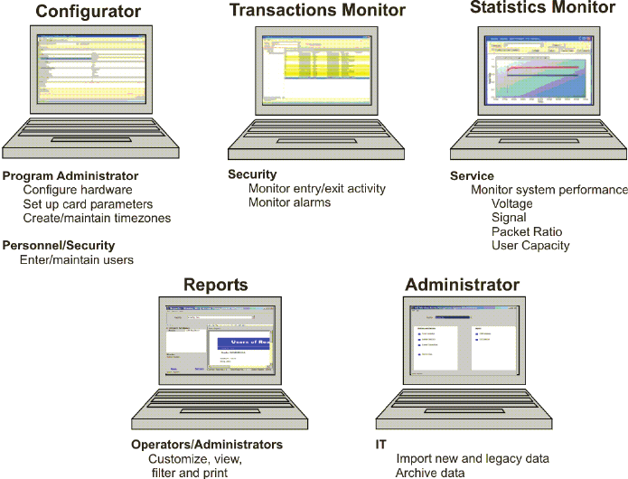
Software Overview
Wi-Q AMS provides powerful tools to manage your system: Wi-Q AMS Configura-
tor, Transactions, and Statistics Monitor help you configure your settings, monitor
transactions in the system, and verify system hardware performance. You can view
and create reports from all applications and perform archivals and imports using Wi-Q
AMS Administrator.
If you are the Program Administrator responsible for setting up communications
between AMS software and system Portals and controllers; you will spend most
of your time using the Configurator module. If you are in personnel or security, you
may be the person who adds users to the system and gives them access privileg-
es and IDs. You will spend most of your time on the Users tab of the Configurator.
If you are responsible to oversee security for your organization, you will monitor
all access and alarm activity using the Transactions module. If you are a Systems
Administrator responsible to ensure the wireless network is operating at maxi-
mum performance, you will use the Statistics Monitor and Administrator modules.
If your organization is small, you may use all applications. Regardless of the tasks
you are responsible to perform, you can view and print reports from all applica-
tions using the Reports module.
11
Figure 2 Five Applications
Once the software is installed, you will find the Configurator module shortcut on
your desktop. You can access all applications from the Configurator main menu.
You can also access these applications from the Windows Start Menu under
Stanley Security Solutions.
12
Setup Checklist
Wi-Q AMS is set up in eleven basic tasks. Completing these tasks will ensure you
get your system up and running as quickly and efficiently as possible.
Some tasks are performed at the Host computer and some at the segment site.
It is appropriate to perform some tasks concurrently, for example, you may have
someone prepare your computer and install the software concurrently with site
plan development and hardware installation. However, you must have the soft-
ware installed and Portal Gateways ‘online’ before you can sign on controllers.
Note System setup does not proceed in a linear manner. The following references
prompt you to skip around within this User Guide.
Task 1: Develop a Site Plan, page 17.
Task 2: Position Portal Gateways, page 21.
Task 3: Prepare your Computer, page 33.
Task 4: Gather and Organize Segment Data, page 43.
Task 5: Install Software, page 45.
Task 6: Create your Segment, page 63.
Task 7: Add and Configure Portal Gateways, page 67.
Task 8: Install Portal Gateways, page 24.
Task 9: Install Door Hardware, page 28.
Task 10: Sign On and Configure Controllers, page 84.
Task 11: Configure AMS Software, page 96.
13
2 Hardware Installation
Hardware Overview
Wi-Q AMS runs remotely with no need for hard-wiring, creating a simple, innova-
tive approach to access control in any environment.
Note Once Wireless Controllers are installed, you will need to sign them on to AMS
software. Therefore, it is appropriate to install the software before or concurrent
with hardware installation. For more information, see “Sign on and Configure
Controllers (Task 10)” on page 84.
Figure 3 is a block diagram showing various configurations. Wi-Q AMS supports
all Wireless Controllers via Portal Gateways (A); and existing Prox/Wiegand,
RQE, door strike, and door monitor switch configurations (B). Configuration types
are briefly described in the following paragraphs. Full installation instructions are
provided in the following sections.
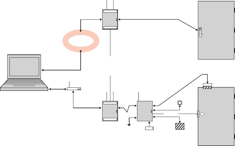
14
Figure 3 Example System Configurations
Portal Gateways
The Stanley Portal Gateway is a wireless device connected to the Host computer
through a secure IP address, similar to the way your computer is connected to the
internet. It transfers data signals from Wireless Controllers to and from the Host
computer. The Portal Gateway recognizes all Wireless Controllers within its antenna
range. One Portal Gateway can be upgraded to control up to 64 Wireless Controllers.
Portal Gateways provide bi-directional radio frequency communication between
Wireless Controllers and the associated host computer(s). All communications are via
secure AES 128-Bit encrypted 2.4 HGz using spread spectrum RF Radio technology.
The Portal Gateway communicates to the host computer through web services via
either Ethernet 10/100 BaseT, approved 802.11 G wireless, or an approved commer-
cial RF carrier-enabling a wireless solution end-to-end. All communications between
Wireless Controllers and Portal Gateways can be further backed up by “redundant”
Portal Gateways each with capacity for up to 64 Wireless Controllers.
Transmit range from Portal Gateway to controller varies based on building construc-
tion. Various factors can affect the range you will see in your facility.
HOST
ETHERNET
10/100 BASE T
802.11g or other
comm. Carrier
LAN/WAN
SECURE
SOCKET
PORTAL
GATEWAY
Up to 64 wireless devices
per portal gateway
(configured in
increments of 16)
WIRELESS ACCESS
CONTROLLER
RQE
STRIKE
12V DC
2.4 Ghz, Spread Spectrum/
AES 128 Bit Encryption
WIRELESS
DOOR
CONTROLLER
DOOR MONITOR
SWITCH
Existing
Prox/Weigand
card reader
Optional 12/24 V
DC Power Supply
Sealed Led Acid
Battery Pack
PORTAL
GATEWAY
A
B
15
Wireless Controllers
Wi-Q AMS software is designed to operate with Wi-Q Technology Best 45HQ
mortise and Best 9KQ Cylindrical locksets equipped with either keypad, card, or a
combination of controller input devices. Wi-Q AMS software is also designed to
work with Omnilock 9KOM cylindrical and 45KOM mortise locksets. Door switch
monitor, request to exit, and door lock position sensors are included in the locks.
Wi-Q and Omnilock Controllers support a broad range of Controller technologies:
Card or Keypad ID with PINs
Magnetic Stripe, Prox, MIFARE (card number only)
512 Timezones (per Segment)
18000 User Credentials per door (based on licensing)
Cardholder access level definition
Dynamic memory for IDs vs Transactions
Locally stored and transmitted transactions
ADA Compliant
No AC required at door
Wireless Access Controllers
You can retrofit any existing controller configuration to communicate with Portal
Gateways using Wireless Access Controllers. You can also use this device to
connect other I/O devices to the system. About the size of a standard double-
gang box electrical box, these controllers operate on standard 12V DC or an
optional 12/24 V DC power supply, sealed, lead acid battery pack. They seam-
lessly integrate existing door hardware into the Wi-Q AMS system, supporting
Wiegand-compatible keypad Controller inputs. Check with your Stanley Repre-
sentative for a list of compatible controllers.
16
Antenna Types and Applications
To optimize system performance, it is important to position Portal Gateways to
receive maximum signal strength from the controllers. Once all door hardware
has been installed, you will be ready to position Portal Gateways using the Wi-Q
Technology Site Survey Tool. Wi-Q and Omnilock Technology support two antenna
types: Omni-directional, designed to provide coverage in all directions; and Direc-
tional antennas that focus the signal from point-to-point over longer distances and
through obstacles. For more information, see Position Portal Gateways (Task 2).
Installing System Hardware
Wi-Q AMS is designed to operate with Stanley Wi-Q and Omnilock Controllers
and Portal Gateways. Detailed installation instructions are provided in the follow-
ing sections and in the lock instructions provided with the hardware which are
included as Appendices to this manual.
What you will need
Engineering drawings or segment map
Wi-Q Technology Site Survey Kit
Wi-Spy Spectrum Analysis Tool by MetaGeek (or equivalent) to identify the
best open channels for your network
For Keypad Controllers, you will need the sign-on credential from the Wi-Q
AMS software
For magnetic stripe or proximity card controllers, you will need the Pro-
grammer ID cards supplied in the software package. You will also need the
appropriate magnetic stripe or proximity USB enrollment controller to create a
proximity sign-on credential.
Locksets to be installed on doors, including cores and keys supplied with
specific model.
Installation instructions for specific lockset brand and model.
Portal Gateways
Access to standby power for 120 VAC non-switch circuit for 12 VDC plug-in
transformer.
10/100/1 GigE Base-T network connection
17
Crossover Ethernet cable if direct connection between Portal Gateway and
Host will be used
Wireless Access Controllers, if used, and knowledge of existing hardware and
switches for any retrofit installations
Installation tools
Drill Motor/hole saw with bits appropriate for the specific lock (see the tem-
plate included in your lock)
Phillips-head and flat-head screw drivers
Access to the Host, a networked workstation, or wireless laptop computer.
Develop a Site Plan (Task 1)
Before installing Portal Gateways, it is a good idea to develop a general plan for
the segment. This plan will guide you in deciding where to install the Portal Gate-
ways. You must consider the following:
Transmit range from Portal Gateway to controller varies based on building con-
struction. Site characteristics such as reinforced concrete walls could interfere
or weaken the signal; open spaces and low interference can increase signal
strength.
Controllers will transmit to the nearest Portal Gateway; however, if for some un-
foreseen event, the nearest Portal Gateway goes down; the controllers are able
to report to another Portal Gateway in the nearby area, providing redundancy in
the system.
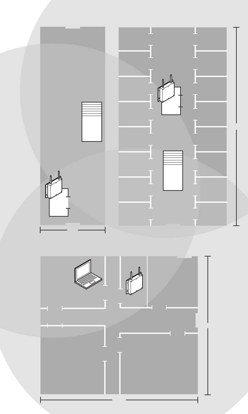
Figure 4 shows a typical site configuration. The Host (A) is located in Building 1.
The Building 1 Portal Gateway (B) is located near the electrical panel in the com-
munications/electronics room. This Portal Gateway will collect transactions from
the 12 controllers in Building 1. As you can see by the gray circle representing the
Portal’s range, it also extends to the entrance of Building 2 and the Parking Ga-
rage. This provides redundant coverage of those areas should either of the other
Portals go off line.
18
The Building 2 Portal Gateway (C) is positioned next to the electrical panel. With
48 rooms in this three-story dorm, front and rear access doors and access to the
elevator on three floors, this gateway provides coverage to 53 controllers. Its
range extends to all three floors of the building, and will also cover the pedestrian
access, and elevator of the Parking Garage. The Parking Garage Portal (D) is po-
sitioned to cover the pedestrian door near the dorm and the stairway and elevator
doors. Its range also extends to the entrance of Buildings 1 and 2.
19
Figure 4 Sample site installation plan
Building 2
C
Comm./
Elect.
Stair/
Elevators
3 Story Dorm Rooms
101-148
Double Occupancy
96 Students
200 ft
102
103
104
105
106
107
108
109101
110
111
112
113
114
115
116
Parking Garage
Stair/
Elevators
Portal
Gateway
D
50 ft
Building 1
Lecture 1
Admin.
6 Staff
Lecture 2
Housekeeping
10 Staff
B
A
250 ft
Host
Portal
Gateway
Electrical
Panel Box
150 ft
20
Plotting the Plan
If you don’t already have a site plan indicating building dimensions, distances be-
tween buildings, possible obstructions, parking segment, and other gated access
points, contact your facilities maintenance or project engineer. If none are avail-
able, you will need to visit the site, take measurements and draw up a plan of your
own.
Device Identification
Each device in the system will have its own unique identity. It will be important
for you to document that identity, along with capacities and locations, and to give
each device a common name such as “Parking Garage” or “Admin 1”. At a mini-
mum, you must record the Media Access Control number (MAC address) for each
device. This 12-digit number is assigned by the manufacturer of a network device
so that it can be recognized as a unique member of a network.
Note The MAC address is most commonly shown on the back of or inside the device, so
it’s important to record this number before you install the device.
When you move on to configure the Host computer, it is essential to have a list
identifying each controller lock and Portal Gateway recognized by the system.
We recommend creating a temporary label for each device that includes the MAC
address, device name, location, capacity, and type of antenna so that installers on
the site will have a reference for installing the correct device in a location.
Redundancy
In our sample plan, approximate Portal Gateway ranges are indicated by shaded
circles. As you can see, these circles overlap, creating a degree of redundancy
in the system. It is perfectly acceptable, in fact, desirable to create range redun-
dancy in your plan. This will provide additional coverage should a Portal Gateway
go off line, intentionally or otherwise. If the controllers find that the nearest Portal
Gateway is down, they will “search” for the nearest Portal Gateway.
Interference
Wi-Q and Omnilock Technology transfers information between devices in the form
of data packets over the 2.4 GHz ISM band. This band frequency is very heavily
used in many devices such as wireless computer networks (802.11 b and g) and
cordless phones, which increases the risk of lost packets, that is, packets that
do not make it from a controller to a Portal Gateway because of interference.
Interference can also reduce controller battery life due to the constant re-broad-
casting of packets and lost connections to the Portals.
21
To achieve maximum efficiency in AMS, this frequency range must be managed
effectively. Therefore, the installer must know the positions and channels of all
the 2.4 GHz wireless devices in the segment and ensure channels are assigned to
each device so that there is minimum frequency overlap with adjacent or nearby
devices.
Extended Range
It is likely that you will have locations in your segment separated by distances
greater than 300 feet. You may want to consider adding a Portal Gateway with a
directional antenna to increase the transmit range.
Note Actual distances will vary based on building construction.
Position Portal Gateways (Task 2)
Once all door hardware and controllers have been installed, you are ready to de-
termine the final placement of Portal Gateways using the results from the Wi-Q
Technology Site Survey Kit. The Site Survey Kit helps you determine the number and
optimum location of Portal Gateways and verify signal strength before permanently
installing the hardware. It is important to perform the Site Survey process as many
times as needed to determine the optimal position.
Note You will need to test signal strength at all door locations near the perimeter of the
coverage area as well as any location where a physical obstruction may cause
interference.
Antenna types
Wi-Q and Omnilock Technology provide two antenna types: Omni-directional,
designed to provide coverage in all directions; and Directional antennas that focus
the signal from point-to-point over longer distances and through obstacles. If you
have trouble verifying signals, you may need to consider some antenna type op-
tions. Figure 5 shows two available antenna types.
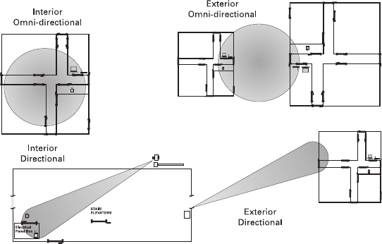
22
Figure 5 Selecting the antenna type that best suits your needs.
Power Supply
Portal Gateways must be located where they can receive 12 VDC power from a
transformer plugged into a dedicated power source. If this is not possible, ensure
they are plugged in to a 24/7 power circuit that cannot be turned off at a switch,
such as a light switch that might be turned off by a cleaning crew.
To make your final determination, you must also consider the following:
Access to Ethernet 10/100 Base T network connection.
Proximity to other I/O device(s) if used.
Placement within range of controllers.
Note Actual distances will vary based on building construction.

23
Troubleshooting
If you have problems establishing communication using the Wi-Q Technology Site
Survey Tool, refer to the following troubleshooting guide:
Next steps
When you are satisfied with signal performance, you can proceed to configure
Portal Gateways using Wi-Q AMS.
If... Then
The green light on the power supply does
not turn on...
Firmly press the power cord into the outlet on the outside
of the case. Confirm that the other end of the power cord is
plugged into a working electrical outlet.
The power supply is on, but the green
light on the Portal Gateway does not turn
on.
Ensure the power cord is firmly connected to the bottom of
the Portal Gateway.
The Stanley Site Survey application
freezes after clicking Connect.
Close the application and reconnect the Host PC to the Stan-
ley survey wireless network.
The Stanley Survey network is not listed
in the Wireless Network Connection
window.
Confirm that the green light on the power supply is on. En-
sure the power cord is firmly connected to the bottom of the
wireless router (under the foam).
The Stanley Site Survey application is not
receiving a signal from a beacon.
Ensure the beacon is powered up. Move the beacon closer
to the Stanley Site Survey kit.
When connecting the battery wires, the
beacon does not power up (the blue LED
on the circuit board remains off and no
confirmation tone sounds).
Disconnect the battery pack wires, wait 10 seconds, and
reconnect. If this does not work, replace the battery pack.
The Stanley Site Survey application is not
receiving signals from any beacons.
Ensure the Ethernet cord is connected to the wireless router
(under the foam). If this does not work, you might need to
change the advanced setup options for the application with
the assistance of your Stanley Security Solutions represen-
tative.
24
Install Portal Gateways (Task 8)
The most common installation site is inside an existing protected area such as a
locked room or other secure enclosure, or above ceiling level. If you are installing
inside a dealer-supplied locked enclosure, refer to the instructions provided with
that equipment. Figure 6 shows a Portal Gateway positioned in a protected area.
Figure 6 Installing a Portal Gateway in a protected area.
Connecting the Portal Gateway and Verifying Operation
Once the Portal Gateway is installed, connect and verify operation:
1 Connect the power supply to the Portal Gateway and plug the transformer into
a dedicated AC power supply (wall outlet). The Power Indicator light should
come on. See Figure 7.
Approx.
5 ft. 6-in. high
(eye level)
Portal
Gateway
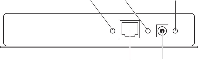
25
2 Insert the Ethernet cable into the Ethernet connection on the bottom of the
Portal Gateway. The Link Indicator light should come on. After about 30 sec-
onds, the yellow activity indicator light will flash under normal operation.
Figure 7 Connecting the Portal Gateway to Power and Ethernet Connections.
Note If no protected area is available, consider positioning the Portal Gateway inside
a locked enclosure designed for that purpose. Contact your dealer for more
information.
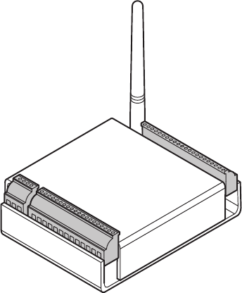
Installing a Wireless Access Controller
The Wi-Q Technology Wireless Access Controller (WAC) provides an optional,
cost effective way to retrofit an existing hard-wired application, or where the in-
stalled controller my be obsolete or unable to handle additional controller inputs.
It supports Wiegand-compatible keypad Controllers and is configured and moni-
tored in Wi-Q AMS the same as a standard controller.
Note Please check with your Stanley representative for a list of compatible controllers.
Using the Wireless Access Controller (Figure 8), you can add controllers or other
I/O devices to an overall wireless solution without the high cost of installing hard-
wire such as RS485 or CAT5 to the controller. You can position the controller at
the door or where suitable above the ceiling tile.
Activity Indicator
Ethernet
Connection
Power
Port
Link Indicator Power Indicator
26
Figure 8 Wireless Access Controller.
Installation
Specific installation methods are dependent on the device type and configuration
of the system; therefore, the WAC should be installed by a trained technician us-
ing the instructions provided with the controller.
WARNING: Wireless Access Controllers are intended for use in indoor or pro-
tected area. For other applications, such as outdoor use, contact the factory for
the appropriate NEMA enclosure. Changes or modifications not expressly ap-
proved by Stanley Security Solutions could void the user’s authority to operate
the equipment.
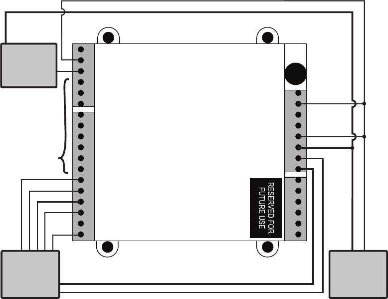
Wireless Access Control Wiring
The Wireless Access Controller (WAC) can be installed with its own 12 VDC
power supply or slaved to the existing installation. Figure 9 is a wiring diagram
illustrating both configurations.
27
Figure 9 Connecting devices to a WAC
Once the WAC is installed and all points connected, it will be recognized by Wi-Q
AMS as a ‘Controller’ in the system. For more information about configuring the
WAC in the software, see “I/O” on page 116.
Weigand
output
reader
12 VDC
Strike Power
Supply
by others
STRIKE NC (Relay 1)
STRIKE COM (Relay 1)
STRIKE NO (Relay 1)
SHUNT NC (Relay 2)
SHUNT COM (Relay 2)
SHUNT NC (Relay 2)
KEY (I/O)
GND
RQE (I/O)
DSM (I/O)
GND
DLS (I/O)
WIEGAND 0 (I/O)
GND
WIEGAND 1 (I/O)
RED
GND
GRN
ANT
DO NOT USE
GND
3.3V (10mA MAX)
DO NOT USE
– DC 9-24V
+ DC 9-24V
– DC 9-24V
+ DC 9-24V
+12 VDC
Connect
as required
GND
(–)
(+)
(+ Power)
(+ Power)
Electric
lock
28
Install Door Hardware (Task 9)
This section provides general instructions for installing your controllers. Complete
instructions for installing locks are packaged with the hardware. You will also
find instructions for Stanley Wi-Q Technology Best 45HQ mortise locks, Best 9KQ
Cylindrical Locks, Best EXQ Trim, Omnilock 45KOM mortise locks, and Omnilock
9KOM cylindrical locks as Appendices to this manual.
Before You Begin
Before you begin, take a few moments to review the following consider-
ations:
Record device MAC address before installing device. You will need this when
configuring the controller in the software.
Wi-Q and Omnilock Technology locks will work from -31°F to 151°F.
Note Extreme heat will cause a reduction in wireless signal strength and can cause a
loss of connectivity while the heat remains.
Note Alkaline batteries cease to operate if they reach a temperature of -20°F.
Wi-Q and Omnilock Controllers are designed for use on 1-3/4-inch doors. If you
need to install on non-standard doors, contact Stanley Customer Service for
more information.
Lockset instructions are given for right-hand doors (as determined from outside
the door). If you are installing a left-hand door, see the instructions provided
with your lockset for hand change instructions.
If you are installing locksets on unprepared (un-drilled) doors, use the template
provided with your specific lockset.
Please refer to the Appendices or the instructions provided with your particular
lock to complete these steps. Once this is done, check controller operation as
described in the following paragraphs.
29
Check Controller Operation
Verify controller operation using the steps appropriate for your controller type
(Magnetic Card or keypad). If the system does not operate properly, see Trouble-
shooting, at the end of the section.
Magnetic Card Check
If your system has a magnetic card controller (mag card), default Programmer
ID cards are supplied with the software. You will need these cards when you are
ready to sign on the controllers.
To perform a magnetic stripe card verification:
1 Determine if the magnetic card type is Track 2 or Track 3.
2 Select the default Programmer ID card that matches the type for your magnetic
card controller.
3 Insert and remove the magnetic card. The magnetic stripe on the card should
be aligned with the ‘V’ mark by the card slot. The lights on the top of the Con-
troller will flash green once and unlock, then during the open delay time, it will
flash green five times. Once this occurs, the card controller light will flash red
and lock.
4 While unlocked, check for proper lock operation.
Keypad Check
If your Controller is a keypad type, perform the following steps:
1 At the keypad, enter the default Programmer ID, 1234#. The green light on top
of the card controller will flash once and the lock will unlock, then during the
open delay time, it will flash green five times. Once this occurs, the controller
red light will flash and the lock will relock.
2 While unlocked, check for proper lock operation.

30
Troubleshooting mortise and cylindrical locks
If the mechanism doesn’t unlock, refer to the following table:
Troubleshooting EXQ Exit Hardware trim
If the mechanism doesn’t unlock, refer to the following table:
For additional troubleshooting instructions, see the Service Manual for the hard-
ware.
Once you have installed and tested your Controllers, you are ready to sign them
on in your system. To do this, Wi-Q AMS software must be installed on your Host
computer. At a minimum, you will need to create your Segment and add your
Portal Gateways to the Segment Tree before you can sign on the Controllers. See
“Add and Configure Portal Gateways (Task 7)” on page 67. Once that is done
you can return to the site and sign on the controllers. See “Sign on and Configure
Controllers (Task 10)” on page 84.
Verify Signal Strength, Voltage and Packet Radio
LEDs Sounder You should...
Single red flash — Use the card at a moderate speed.
Red flashes 3 short tones Use the temporary operator card provided
with the lock.
Green flashes —Check the motor connection.
— — Check the battery connection.
LEDs Sounder You should...
Single red flash — Use the card at a moderate speed.
Red flashes 3 short tones Use the temporary operator card provided
with the lock
or
Perform a door reset to restore to the fac-
tory default settings (the lock may already
be associated (programmed).
Green flashes —Check the motor connection.
Alternating red and green
flashes
—Check the motor connection.
— — Check the battery connection.
31
If you used the Wi-Q Technology Site Survey Kit, you have already verified basic con-
troller signal strength. Once the controllers are signed on, you can use the Statistics
Monitor application to further measure controller performance, including controller
voltage (battery level), and the packet ratio (the number of packets received vs the
number of packets sent) of the controller. For more information about the Statistics
Monitor application, see “Statistics Monitor” on page 191.
32
Stanley Wi-Q AMS provides powerful suites of tools to manage your system: Con-
figurator, Transactions and Statistics Monitor. View reports from all applications
using Reports, and perform archivals and imports using Administrator.
Once the software is installed, you will find the Configurator shortcut on your
desktop. You can access all applications from the Configurator main menu. You
can also access these applications from the Windows Start Menu.
The following setup tasks are covered in this section:
Task 3 — Prepare your Computer
Task 4 — Gather and Organize Segment Data
Task 5 — Install Wi-Q AMS Software
3 Software Installation

33
Prepare Your Computer (Task 3)
To prepare your computer for the installation of the Wi-Q AMS software, you must
ensure that your system is equipped with an appropriate operating system, data-
base and server and configure your Windows Firewall Ports.
Recommended System Limits
It is important to ensure your Host computer or computers are adequate to handle
the system. The following table lists the recommended system limits for running
Wi-Q AMS.
Hardware configuration
Parameter
Config 1 Config 2* Config 3* Config 4*
CPU Speed 1 cores @ 3GHz 2 cores @ 3GHz 4 cores @ 3GHz 8 cores @ 3GHz x 2
machines (SQL server
& communication
server)
RAM 1 GB 4 GB 4 GB 8 GB
Hard Disk 40 GB 40 GB 40 GB 100 GB
OS Windows XP,
Windows 7
Professional,
or Windows 7
Ultimate
Windows 7
Ultimate 64 bit
Server 2003 32 bit,
Server 2008 32
bit, or Server 2008
64 bit
Server 2008 x64
SQL Version 2005 Express or
newer
2008 Standard 2008 Standard 2008 Standard
Portal Gateways 50 100 250 1000
Devices 300 1000 3000 10000
Users 1000 5000 10000 50000
Segments 1 1 1 1
Ethernet 1000 Base T 1000 Base T 1000 Base T 1000 Base T
* — requires tuning of system parameters during installation by Stanley Security Solutions Technical Support
34
Configure Windows Firewall Ports
Several ports must be enabled in your Windows firewall settings to allow proper
communication with AMS. The following ports must be enabled:
Port 23
Port 80
Port 1433
Port 1434
Port 8000
Port 11000
Port 5353
If your firewall is disabled, then all ports are open by default. If the firewall is on,
perform the following steps in order to add the required ports listed above:
35
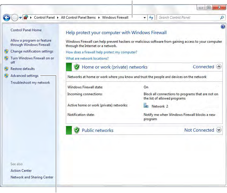
Note The screenshots below reflect a Windows 2007 operating system. Navigating
through the firewall settings in other editions of Windows will be slightly different.
1 Navigate to your Windows Firewall settings from your PC’s control panel. See
Figure 10. Then, click on Advanced settings.
Figure 10 Windows Firewall
Navigate to Windows Firewall
Click on Advanced settings
36
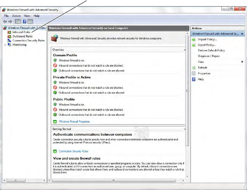
2 Select Inbound Rules.
Figure 11 Inbound Rules
Select Inbound Rules
37
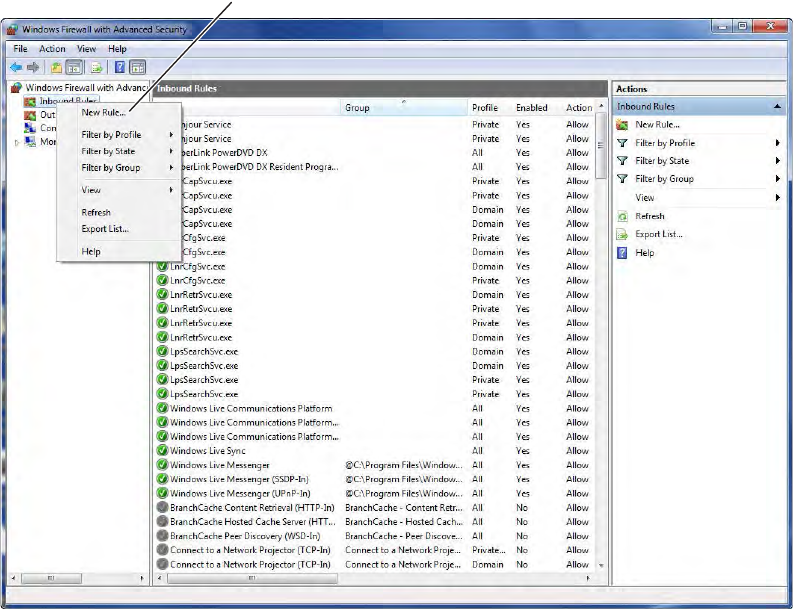
3 Right click on Inbound Rules to open an option menu. Select New Rule from the
menu.
Figure 12 New Rule
Select New Rule
38
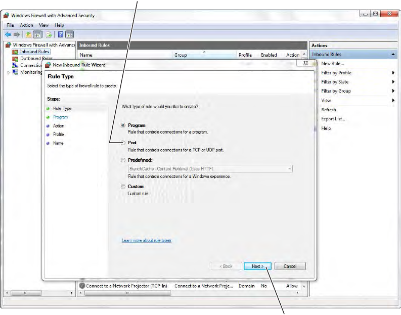
4 In the New Inbound Rule Wizard window, select Port. Click Next to continue.
Figure 13 Create Port Rule
Select Port
Click Next
39
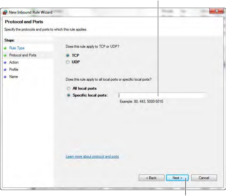
5 Enter the following ports into the “Specific local posts” field: 23, 80, 1443, 1434,
8000, 11000, 5353. Then, click Next to continue.
Figure 14 Enter Ports
Enter ports: 23, 80, 1443, 1434, 8000, 11000, 5353
Click Next
40
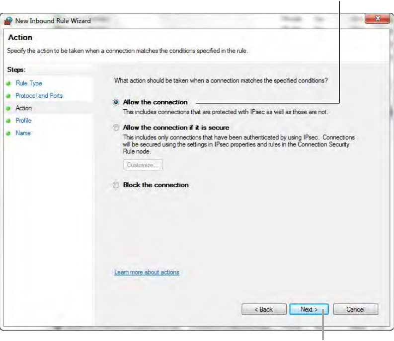
6 Select Allow the connection. Click Next to continue. See Figure 15.
Figure 15 Allow the Connection
Select Allow the connection
Click Next
41
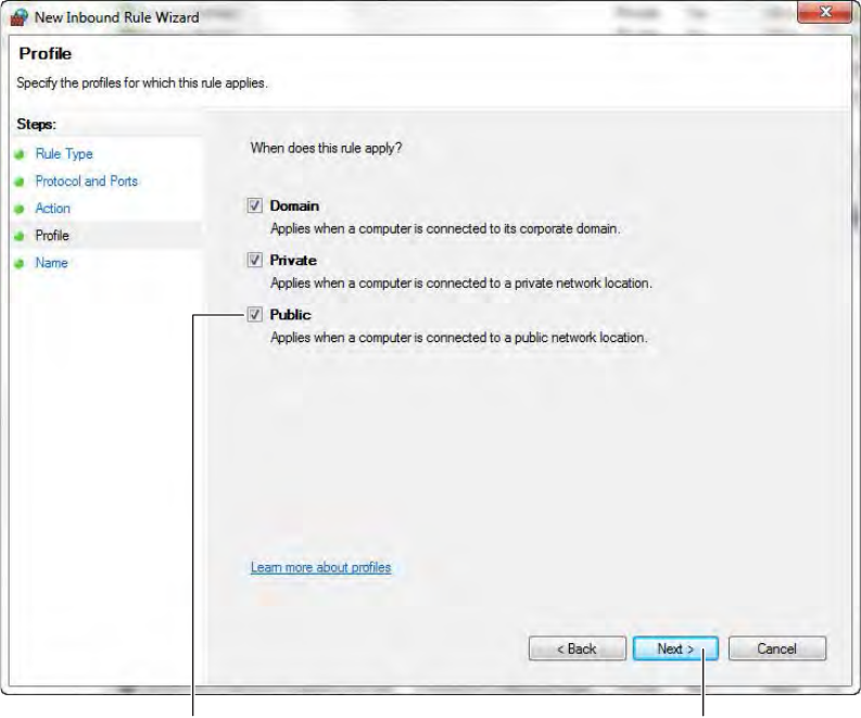
7 De-select the Public option. Click Next.
Figure 16 De-select Public
De-Select Public Click Next
42
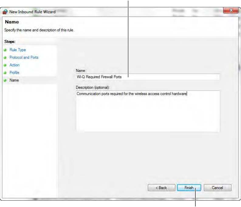
8 Give the new rule a name that can be easily identified by an administrator.
Once finished, click Finish. See Figure 17.
Figure 17 Name the Rule
Name the Rule
Click Finish
43
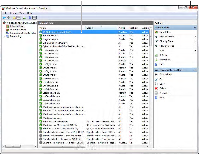
9 The new rule now appears in the list. The Firewall Settings module may now be
closed. See Figure 18.
Figure 18 Inbound Rules List
Gather and Organize Segment Data (Task 4)
As the technical team works on planning and installing hardware using the Site
Plan, a program administrator or other person responsible for the software side of
program setup should be making plans to populate and configure Wi-Q AMS.
Device Information
You will need the MAC numbers, device names, capacities, and physical locations
of all Portal Gateways so that you can easily identify them and assign them to the
correct location within the AMS Segment Tree. Ensure your site technical team
will provide you this information as they work their way through the site.
New Rule shows in list Click to close

44
User Information
You will also need to gather the names of users, define their access requirements,
organize user and timezone groups, and decide how you will use other features
configurable within AMS.
It will be helpful to create a table listing what you know about each user. Start-
ing with a list of names, think about building a table that defines basic information
about each user; such as, User Type, User Group, Shift, and so on. Following is a
very simple example:
What User Groups will help you manage security? Do you have shift workers who
are allowed on site only during certain days or hours? Will there be areas off lim-
its to certain groups? Do some users need extra time to pass through a door, such
as to accommodate a food cart or wheel chair? Start thinking about these ele-
ments and begin organizing the data as soon as possible so you’ll be ready when
your equipment and software are ready. It is a good idea to use a spreadsheet
software such as Microsoft® Excel® for this purpose. That way you can sort the
data to help you plan your segment.
Importing Data
Do you have an existing database that already contains much of the information you need?
It is likely you can modify a version and import it into AMS using the program’s System
Administrator feature. If you have a large organization, this will save you time and reduce
data entry error. See “Importing Data from a Legacy OFM Database” on page 170.
Last User Type
Alverez
Bennet Fred
Ford Aldo
Manager
General
General
Bldg.
A
A
B
User Group
Admin
Lecture
Service
Timezone
Default
Default
Service 1
First
Alicia
Shunt
Default
30 sec.
30 sec.

45
Install Software (Task 5)
The AMS software is installed in three steps: Install the Database Server compo-
nent, Install Wi-Q AMS Web Services, Install Applications.
Note The installation may detect missing prerequisites during the installation process.
Have your original Microsoft Windows installation disks ready for use if prompted
(Configuration #5 – Server PC (Pro and Enterprise Region Systems). In addition, be
prepared to address the following conditions during the setup:
Beginning Installation
1 If you have not already done so, download the Wi-Q AMS Software from the
Stanley Technical Support website
or
Insert the software disc into your machine’s disc reader.
Note If you have downloaded the installation files to your machine, it is recommended
that you save the folder directly on your local hard drive to keep the path to the
files as short as possible.
2 Click on the .exe file that contains “Bootstrap”
(Example: WiQBootstrap.exe).
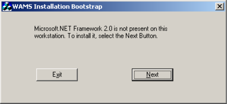
3 Wi-Q AMS Setup checks your workstation for any missing prerequisites, such
as Microsoft.NET Framework. If the following dialog box opens, click Next. If
not, proceed to Step 4.
If... Then
If you plan to use a secure socket
layer (SSL) connection (connecting
via the internet)
You plan to use a basic
authentication
You plan to use certificate
mapping
A client certificate file must be generated. See
your Network Administrator.
A local administrator user account, login, and
password must be generated for the system to
log into. (Instructions are presented in Portal
Gateway Setup, Setup tab, Host Access Settings.)
A valid certificate must be obtained
from a certificate authority for IIS.
See your Network Administrator.
46
Figure 19 Installation Bootstrap
a The Microsoft .NET Framework Setup wizard welcome screen opens. Click
Next to continue.
b Read the End-User License Agreement. To continue with the installation,
click the checkbox at the bottom. Then click Install. The installation may
take a few minutes.
c When the installation is complete, click Finish.
Note It is recommended that you reboot your machine after any missing prerequisites
are installed before continuing on with the installation.
d After rebooting your machine, click the “Bootstrap” .exe file again.
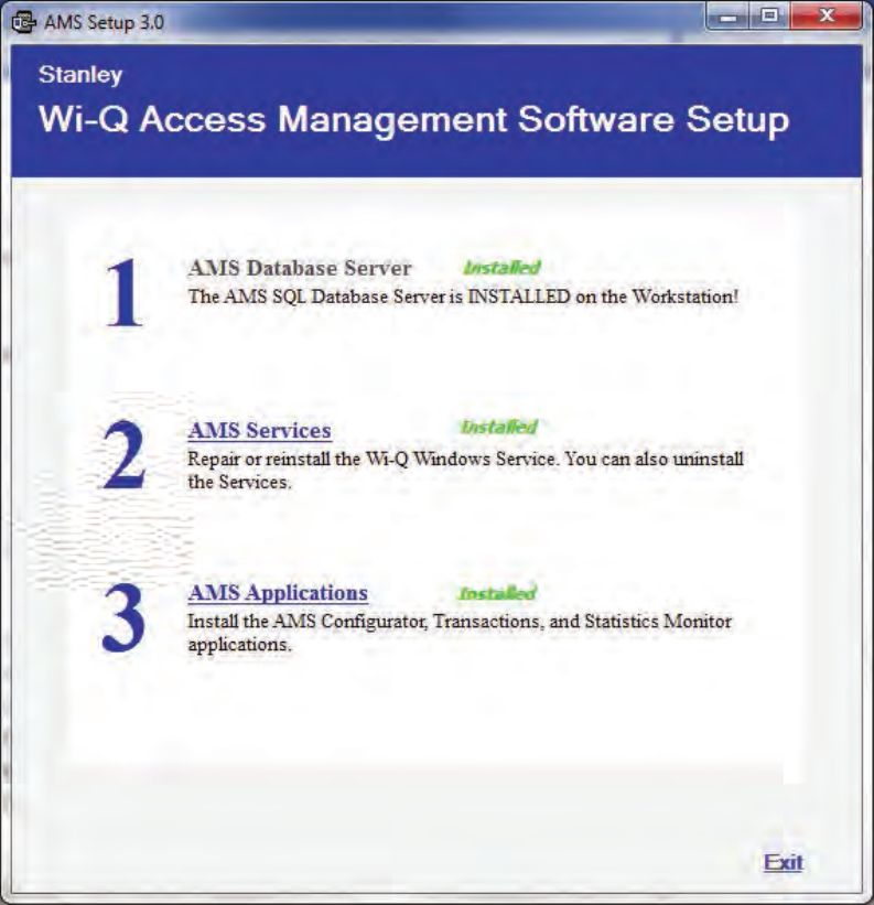
4 The AMS Setup Main page opens, Figure 20. It is important to perform the
steps in the sequence presented.
Note You may wish to install the services and database on one machine (such as the
Host) and the AMS Applications only at other machines. This can be done by
selecting the appropriate application from the System Setup windows.
Note The screen shots in this User Guide are from a Stanley Wi-Q AMS system.
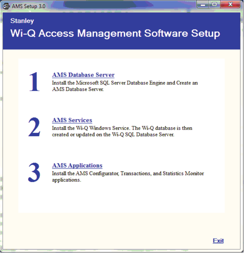
47
Figure 20 AMS Setup
48
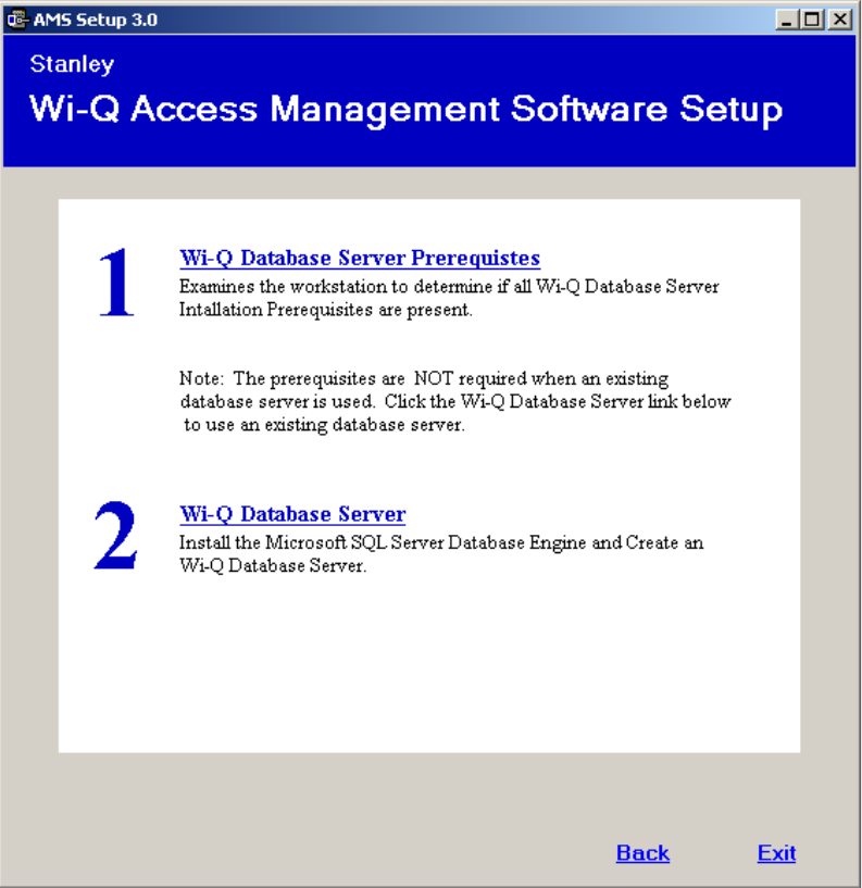
Step 1
1 Click the AMS Database Server link. If a similar dialog box opens with a link to
install Prerequisites, click the link.
Figure 21 Database Server Prerequisites
2 You may be prompted to install a number of prerequisites, including Microsoft
Windows Installer and Windows PowerShell. To install the latest versions of
these prerequisites, it is recommended that you click the website links provided
and download directly from the Microsoft website. Once you’ve downloaded
the setup files, follow the installation prompts provided.
Note It is recommended that you reboot your machine after any missing prerequisites
are installed before continuing on with the installation.
49
3 Once all the prerequisites have been installed, click the link on the main setup
screen to install the AMS Database Server.
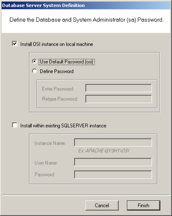
4 The Database Server System Definition dialog box opens. Choose whether to
install the server on a local machine or within an existing SQL Server instance.
If you choose to install on a local machine, decide whether to use the default
password or define a new password. If you choose to install within an existing
server, enter the instance name and associated user name and password. Then
click Finish.
Figure 22 Database Server System Definition
5 The SQL Database Server will install now. This may take several minutes.
50
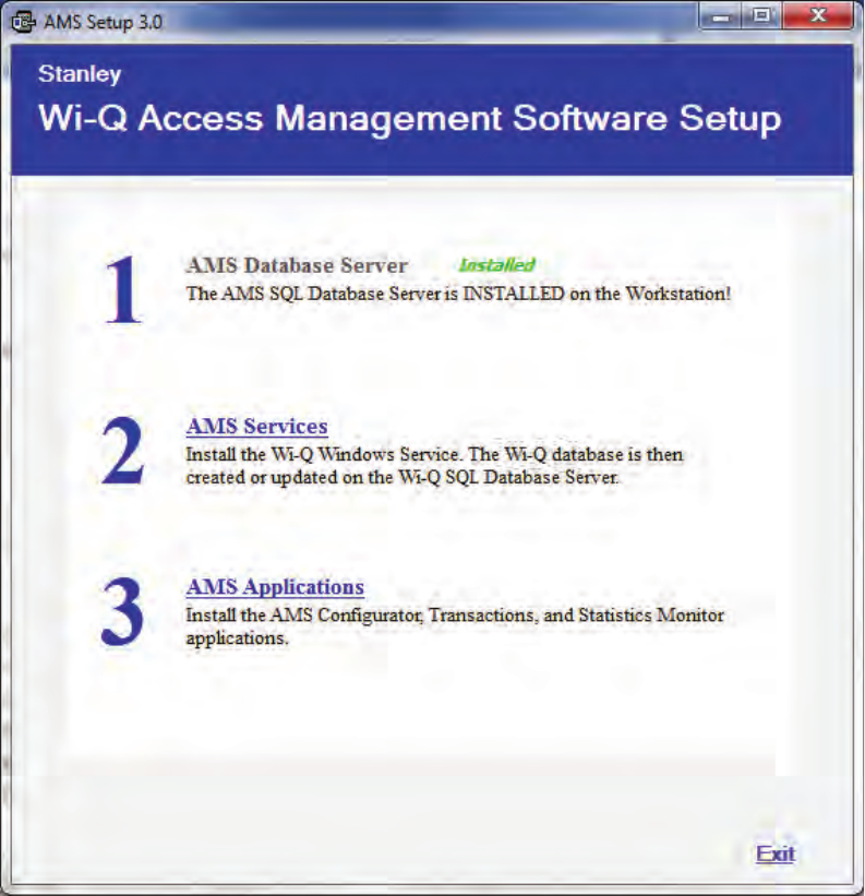
6 When the server is successfully installed, you will see “Installed” next to Step
1. As you work through the process, steps that have been completed or don’t
need attention will no longer have clickable links.
Figure 23 AMS Database Server Successfully Installed
51
Step 2
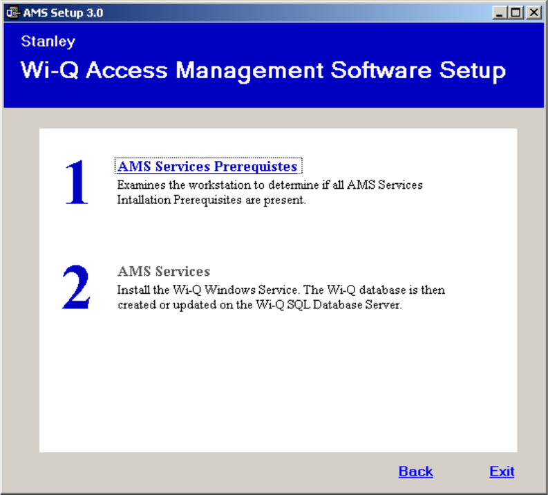
1 On the Setup main page, click the AMS Services link.
2 If a similar dialog box opens with a link to install Prerequisites, click the link.
See Figure 24.
Figure 24 Install Prerequisites
a You may be prompted to install Apple® Bonjour®. Bonjour networking tech-
nology is used by the Portal Configuration Tool to locate and list all Portal
Gateways on the network. Click the link to begin installing Bonjour.
b The Bonjour Print Services window opens. Click Next to continue.
52
Figure 25 Bonjour Print Services Installer
c Read the License Agreement. To continue with the installation, click on “I
accept the terms in the license agreement,” then press Next.
Figure 26 Bonjour Print Services License Agreement
53
d Read the information about Bonjour Print Services. Then press Next.
Figure 27 Bonjour Print Services Information
54
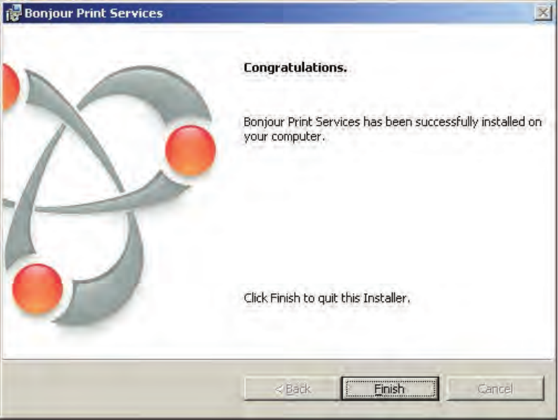
e In the Installation Options section, decide whether or not to create a desk-
top shortcut and/or schedule automatic updates for Bonjour. Choose your
destination folder and then select Install.
Figure 28 Bonjour Installation Options
55
f Once the Bonjour Print Services Installation is complete, press Finish.
Figure 29 Bonjour Print Services Installation Complete
3 Click on AMS Services to install the Wi-Q/Omnilock Windows Service and cre-
ate a database.
4 Click Next to continue past the Welcome page.
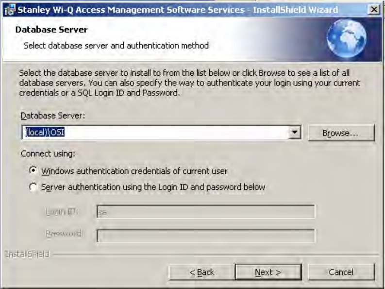
5 On the Database Server dialog box, browse to your database server and select
your connection method. In the Connect Using section, choose your connection
method. If you choose Server authentication, provide the Login ID and Pass-
word for the server. See Figure 30
56
Figure 30 InstallShield Wizard Database Server
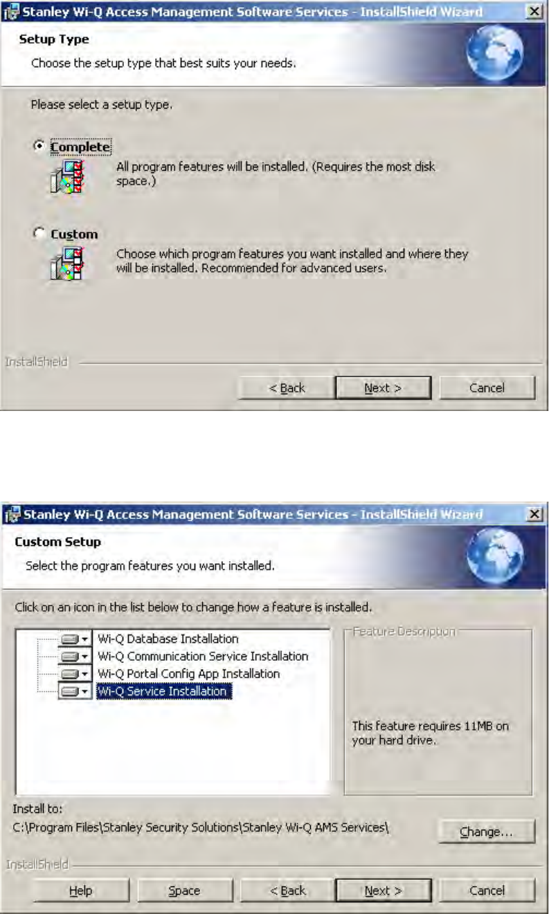
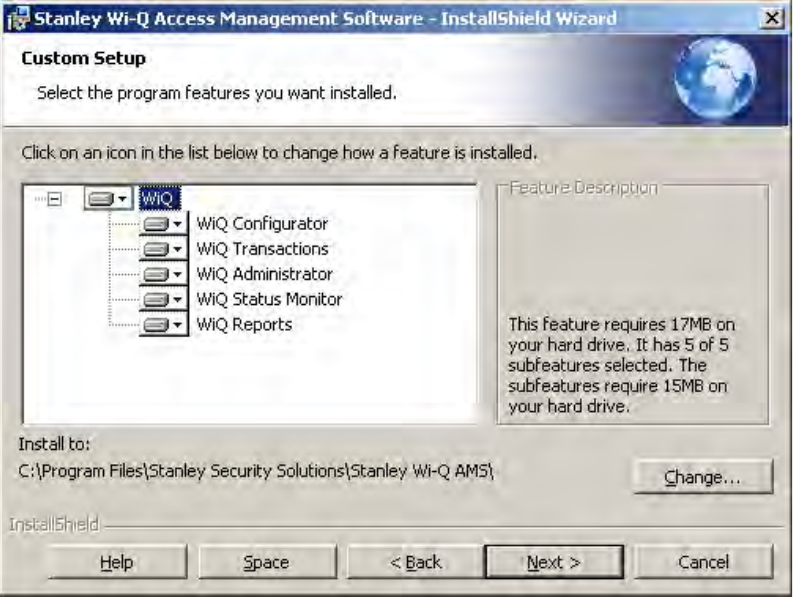
6 In the Setup Type dialog box (Figure 31), select a Complete or Custom install.
Selecting Complete will run installations for the Database, Communication
Service, Portal Config App and Wi-Q/Omnilock Service. Selecting Custom
will allow you to choose which components to install. Once you’ve made your
selection, press Next to continue.
57
Figure 31 Setup Type
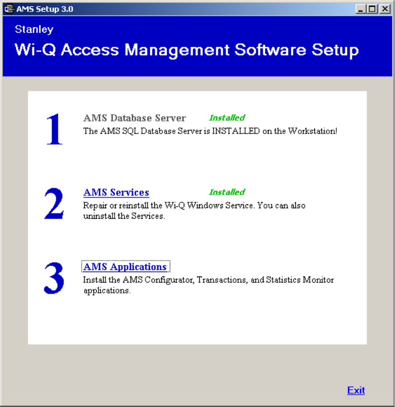
Figure 32 shows the installation components available in a Custom Setup.
Figure 32 Custom Setup
58
Clicking on the icons to the left of each component will bring up installation
options. If you decide on a Custom Setup, you must select an installation option
for each component. Then click Next to continue.
7 The wizard is now ready to begin installation. Click Install.
8 Once the installation is complete, click Finish.
Step 3
1 On the Setup main page, click the AMS Applications link.
Figure 33 Install AMS Applications
2 On the InstallShield Wizard Welcome screen, click Next to continue.
59
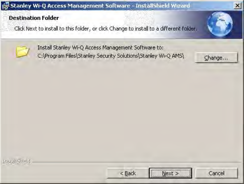
3 On the Destination Folder screen, click Change if you would like to change the
install folder location and browse to the desired location. Then, click Next.
Figure 34 Destination Folder
4 In the Setup Type dialog box, select a Complete or Custom install. Selecting
Complete will run installations for the Configurator, Transactions, Administra-
tor, Status Monitor and Reports applications. Selecting Custom will allow you
to choose which components to install. Once you’ve made your selection, press
Next to continue.
60
Figure 35 shows the installation components available in a Custom Setup.
Figure 35 Custom Setup
Clicking on the icons to the left of each component will bring up installation
options. If you decide on a Custom Setup, you must select an installation option
for each component. Then click Next to continue.
5 The wizard is now ready to begin installation. Click Install.
6 Once the installation is complete, click Finish.
61
The installation of all three components is now complete.
Figure 36 Successful System Setup
Click Exit on the Setup window. Wi-Q AMS will be accessible through your Start
Menu.
Note It is recommended that you reboot your machine after installation is complete.
If you chose a non-standard database server location in Step 1, you must reboot
your machine now.
62
4 Configuring Segments, Portal Gateways
and Controllers
This chapter contains detailed steps to perform the following tasks:
Task 6: Create your Segment
Task 7: Add and Configure Portal Gateways
Task 10: Sign on and Configure Controllers
After segment creation, this chapter discusses Portal Gateway and Controller
configuration. However, it is perfectly acceptable to add Users, User Groups and
any special Timezones you will need before configuring Portals and Control-
lers. An advantage to adding Users and User Groups before you add Portals and
Controllers is that they will be available as you configure each new Portal and
Controller in the system. You can also add Portals, Controllers, users and user
groups as you go, building the system in any way that makes it efficient with the
data that you have available.
Note The terms “Controller” and “Reader” are used synonymously throughout this
chapter.
63
Create Your Segment (Task 6)
It is important to give some thought to how you will go about configuring a seg-
ment in AMS. If you have not already done so, it may be helpful to review the
Getting Started Guide.
Logging in to Configurator
To get started, open your Configurator module. You can access it via the icon on
your desktop or from the Windows Start Menu (Programs>Stanley Security Solu-
tions).
The Wi-Q AMS splash screen appears briefly, then the Login dialog box opens.
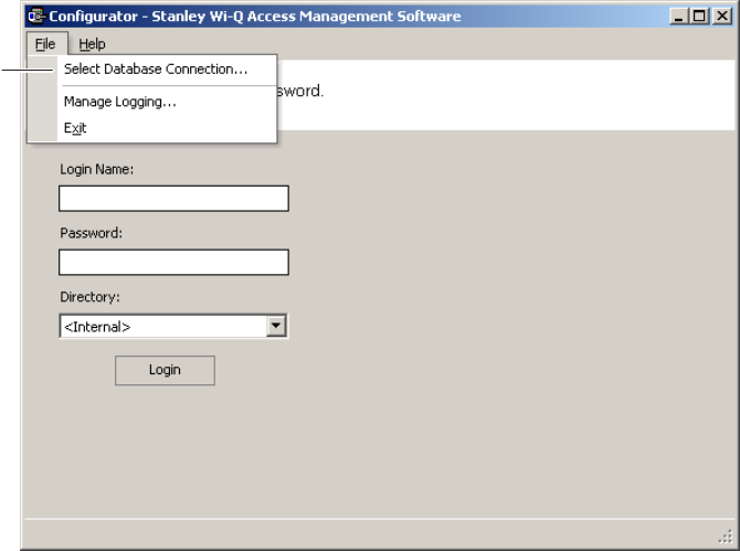
Selecting the Database Connection
When you start up AMS, the system defaults to the database installed on the Host
computer. If for some reason your database resides on a computer other than the
one running AMS, you must select the database before you login.
To select a database on a different computer
1 From the File menu, select Select database connection from the drop-down list.
Figure 37 Select Database Connection
The Database Connection dialog box opens. See Figure 38.
Figure 38 Database Connection Window
Click on Select
Database
Connection
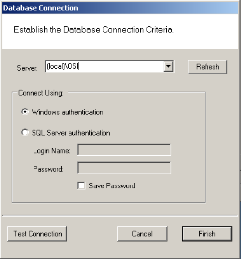
64
2 In the Server field, select the server location from the drop-down list.
3 Under Connect Using, select either Windows authentication or SQL Server
authentication. If you select SQL Server, enter the login name and password for
that server.
4 Click Test Connection.
5 Click Finish. You are ready to login to AMS using your desired database.
Login Information
When you enter the system for the first time, the default, case-sensitive, User
Name and Password are:
Login: Admin
Password: Admin
1 Enter the Login Name and Password.
2 Select Login. You are ready to start setting up your new segment.
65
When you select Login, the Define a New Segment dialog box opens.
Define a New Segment
1 In the Segment Name box, enter a unique name for your segment.
Figure 39 Define a New Segment
2 Select Finish. The Configurator dialog box opens on the Segment Tab. The new
segment name appears in the Selected Segment box and AMS assigns it a
unique Segment ID.
Figure 40 Identifying the Segment name and ID
Note Once you have successfully logged in, it is recommended that you change the default
User Name and Password to ensure system security.
Segment name
Segment ID
66
To change the Password
1 At the top left corner of the Configurator dialog box, select File>Change Pass-
word. The Set Password of User dialog box opens.
Figure 41 Set Password of User
2 Enter the new password
3 Retype the new password.
4 Select Finish.
WARNING: Be sure to keep a record of your new password in a locked safe that
is available to your senior management team!
67
Add and Configure Portal Gateways (Task 7)
Portal Gateways can now be added and configured within the software. Portals
are configured from the factory with an IP address of 192.168.1.200. When config-
uring a Portal Gateway, it is best to connect directly to the Portal before placing
it on the network. This removes the possibility of duplicate IP addresses on the
network.
You can change the IP address of your Portals with the Portal Configuration Mod-
ule.
Note All Portal Gateway IP address must be unique across the entire system.
Configuring a Portal Gateway with the Portal Configuration Module
Perform the following steps to change your Portal Gateway’s IP address.
1 Connect the Portal Gateway to the Host either over the network or directly via
crossover Ethernet cable (recommended). For more information on connecting
a Portal Gateway, see “Connecting the Portal Gateway and Verifying Opera-
tion” on page 24.
2 Open the Portal Configuration module (Start Menu>Stanley Security Solutions>Stanley
Wi-Q AMS Tools).
3 Portals available on the network will automatically be listed in the Portal Con-
figuration module.
Figure 42 Portal Gateways Available on the Network
68
4 Select a portal from the list.
5 At this point, you may change the IP address from the factory setting to one
from the range you’ve created. Click on Update IP Configuration to update the
selected portal.
6 Select IPv4 and/or IPv6 and enter the IP address.
7 You may need to adjust the SubNet Mask/Network Destination and Gateway to
match your network. Consult your network administrator for details.
8 If you wish to generate a SSL certificate for a more secure connection, click
on the SSL Enabled checkbox, then click OK.
Note If you enable SSL, you must create a certificate and load the certificate into your
system.
Figure 43 Update IP Configuration
69
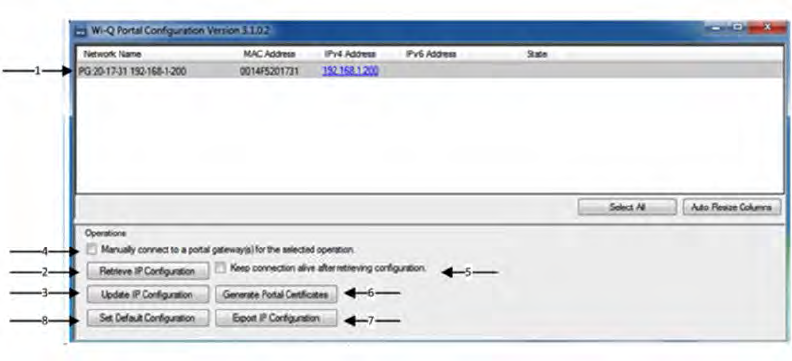
Portal Configuration Features and Functions
Review this section for additional information regarding the Portal Configuration
window. See Figure 44.
Figure 44 Portal Configuration Window
1 Portals on the Network grid
Provides a list of Portal Gateways on the network. It shows the status of the
last operation performed, the portal network name, a hyperlink that opens the
corresponding status page, portal MAC address and portal IP configuration
data.
2 Retrieve IP Configuration Scan
When checked, attempts to retrieve the current IP Configuration for the
corresponding portal. This requires direct communication with the portal con-
figuration service, which only runs for one hour after a reboot. If the service is
not running, the IP Configuration data will return unknown data.
3 Update IP Configuration
Updates the IP Configuration of the selected portal. This requires direct
communication with the portal configuration service. The “New Portal IP Con-
figuration” fields are used for the new IP Configuration data.
4 Manual Connection
When checked, allows a portal to be configured by IP address. Some net-
70
works do not allow port 5353 to be open, which is required by the application
when scanning for portals. This allows manual connection to the portal so
the portal can be configured. You must click on Update IP Configuration after
selecting this box.
5 Keep Connection Alive Checkbox
Allows the connection with the portal to continue, otherwise a reboot will oc-
cur after the action selected.
6 Generate Portal Certificates
Generates a portal certificate that is sent to the portal and stored to the file
system. Enable this box when data encryption is required. Multiple portals
can be selected when generating certificates.
7 Export Portal IP Configuration
Exports the portal IP configuration for the selected portals.
Set Default Configuration
Clear Transactions
When checked, allows you to clear all transactions from portals you select in
the list above. This may be selected in combination with the Set Back to Factory
Default checkbox. .
Set Back to Factory Default
When checked, allows you to set change the IP address(es) of the portal(s) you
select in the list above back to factory default (192.168.1.200). This may be select-
ed in combination with the Clear Transactions checkbox.
71
Once you’ve configured your Portal Gateways with the Portal Configuration mod-
ule, you can add them into your Wi-Q AMS Software.
Adding Portal Gateways to AMS
Portals can be added to your system in two ways:
Adding — normally use this method if the number of Portal Gateways is man-
ageable. This is a manual method that requires manual entry of the IP address
of each Portal Gateway.
Bulk Importing — normally use this method for large systems. This is done
through the System Administrator application through the ‘Import Portals’
selection.
72
Adding Portal Gateways One at a Time
Refer to Figure 45.
1 In the Configurator application, click the Portals Tab.
2 Click Add and the Configure New Portal Gateway screen opens.
3 In the Workstation field, select the location of your server.
4 Enter the name and description of the Portal Gateway.
Note Normally name Portal Gateways by their location. For large systems, work out a
naming scheme that makes it easy to locate the Portal Gateway in your segment.
5 Enter the IP address of the Portal Gateway. You will need to get IP addresses
from your network administrator.
6 Enter the port.
Figure 45 Configure New Portal Gateway screen
7 Click the ellipsis button next to the Channels field and select at least two chan-
nels that the Portal Gateway will use to communicate. Check with your network
administrator to make sure the channels are available.
73
8 Click the ellipsis button next to the Update Interval field. Here you can set how
often the system will update the Portal Gateway with changes you’ve made to
users, readers, timezones, and other functional changes to the database.
9 Click the ellipsis button next to the Transactions field to select which, if any, Portal
Gateway transactions you want to enable and which you want to make a ‘priority.’
Priority transactions will be uploaded immediately rather than waiting for the next
‘update interval’ that was set in the field above. Two transactions are available:
Portal Firmware Update
Portal Radio Start Failed
If you click on Select All, a dialog box window will ask you to confirm your
choice and it will also ask if you would like to enable priorities as well.
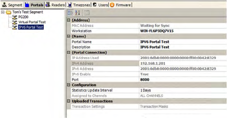
10 If you generated SSL certificates within the Portal Configuration module, you
may browse to your Portal Gateway’s certificate by clicking on the ellipsis
button next to the SSL Certificate field. The Certificate can be found in your
Program Files at the path shown below (Figure 46). The file is located within a
folder named for the Portal Gateway’s IP address. Select the file with the .pfx
extension, and click Open.
Figure 46 Path to Certificate File
11 Click Finish.
The Portal(s) you have added will now be visible in the Segment Tree. See “View-
ing the Segment Tree” on page 79. You can check the operational status of your
Portal(s) by clicking on the top folder within your Segment Tree.
74
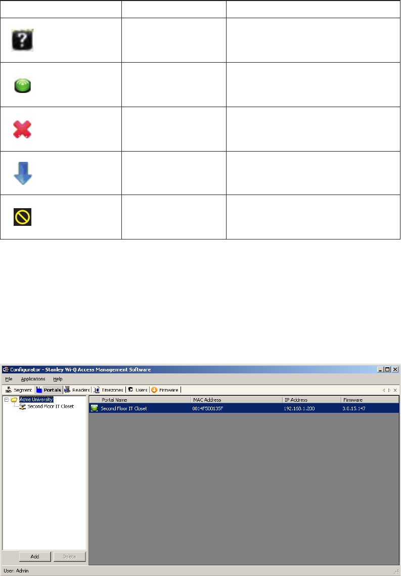
Portal Gateway Operational Status
When you are on the Portals tab within the Configurator module, you can click on the
top folder within your Segment Tree, and the right side of the screen will change to a
list of Portals in your system. The icon next to each Portal will give you the Portal’s
operational status. Five different status icons are present in the system for Portal
Gateways:
If your Portal Gateways have blue down arrow icons, restart your Communica-
tion Server. See “Restarting your Communication Server”. After you restart your
Communication Server, your Portal Gateway status icons should change to green
circles, indicating that the devices are online. See Figure 47.
Figure 47 Portal Gateway with Green Circle Icon
Icon Name Description
Question Mark Device is loading.
Green Circle Device is online.
Red X Device is offline.
Blue Down Arrow Portal Gateway or Controller is not assigned
to a workstation or the workstation is not
running.
Out-of-Date Firmware Incompatible or Out-of-Date Firmware, all
features may not be supported
75
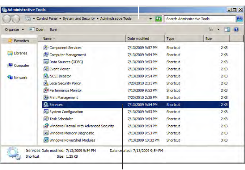
Restarting your Communication Server
If you need to restart your Communication Server, navigate to your system’s Ser-
vices via Administration Tools. See Figure 48.
Figure 48 Navigate to Services
Next, locate “Stanley Wi-Q Communication Service” in the list of services. Right-
click on the line and select Restart.
Navigate to Administrative Tools
Click to Open Services
76
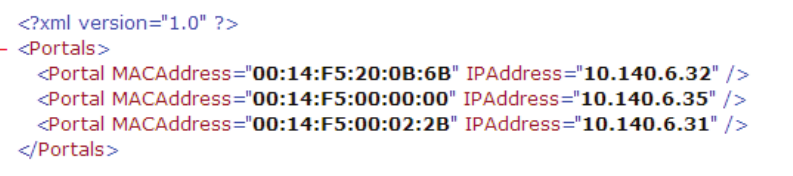
Importing Portal Gateways in Bulk
Before you can import Portal Gateways in bulk, you must generate an XML bulk
import file using the Portal Configuration module.
Generating an XML Bulk Import File
The XML file you will generate documents and cross-references Portal Gateways’
Mac addresses and IP addresses. Perform the following steps inside the Portal
Configuration module.
1 Click on Scan to generate a list of Portals in your system.
2 Select all the Portals you wish to add to your AMS software.
3 Click on Export Portal IP Configurations (see Figure 44).
4 Choose a location to save your XML file, and click Save. Figure 49 shows a
sample XML file.
Figure 49 Sample XML file
Once you have generated your XML bulk import file, perform the following steps.
1 Start the System Administrator module (Applications dropdown menu inside
Configurator).
2 Click the Import Portals link from the Import pane. See Figure 50.
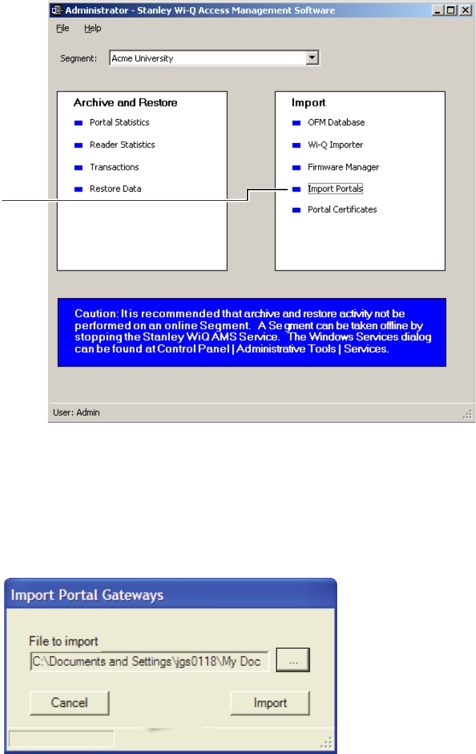
77
Figure 50 System Administrator Portal Gateway Import
3 The Import Portal Gateways dialog displays.
4 Click the ellipsis button and locate the bulk import XML file.
5 Click Open.
Figure 51 Import Portal Gateways
6 Click Import.
Note The Portals are imported (or updated) and a results box details the import. The
MAC addresses should automatically show up in Portal Gateways’ properties.
Click the Import
Portals Link
78
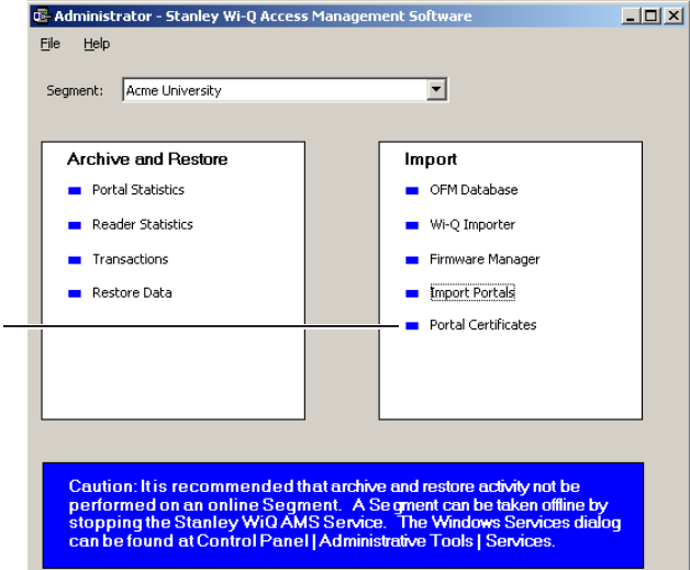
Importing Portal SSL Certificates
If you previously generated SSL certificates for your Portal Gateways, you may
import them now. Perform the following steps.
1 From the System Administrator application, click the ‘Portal Certificates’ link
under the Import pane. See Figure 52.
Figure 52 System Administrator Portal Certificates link
2 Choose the Portal Gateway that you want to import an SSL certificate to and
click the ellipsis button next to it. Then find the certificate file (see Figure 46)
and click Open.
3 When finished with importing all the Portal Gateway SSL certificates, click Fin-
ish.
The Portals you have added will now be visible in the Segment Tree. See “View-
ing the Segment Tree”. You may now check the operational status of your Portal
Gateways. See “Portal Gateway Operational Status” on page 74.
Click the Portal
Certificates Link
79
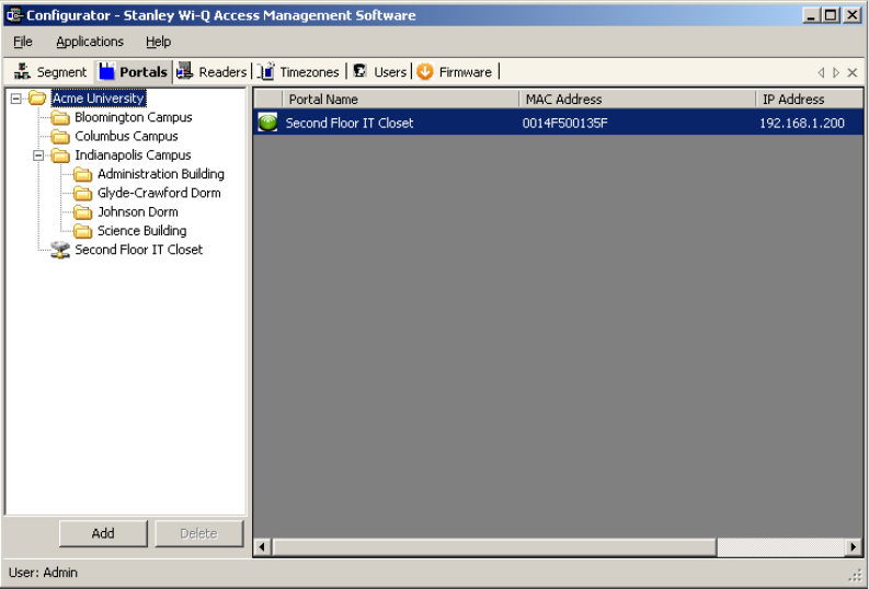
Viewing the Segment Tree
The Segment Tree is a visual representation of the locations and associations of
the Portal Gateways, associated Controllers and I/O devices in your segment. As
you configure your Portal Gateways, sign on Controllers and configure additional
hardware in your system, you can drag them to the folders and subfolders you
create in the Segment Tree.
Figure 53 shows an example Portal Gateway in the Segment Tree.
Figure 53 Portal Gateway visible in Segment Tree
To view the Segment Tree
1 In the Segment tab, select the segment you wish to work with.
2 Click on the Portals tab. The Segment Tree pane displays on the left, and a list
of all prepared devices displays on the right. The first item in the Segment Tree
is the folder for the selected segment, in this case, Acme University.
The Segment Tree is also viewable from within the Readers tab. See “Adding Con-
trollers to the Segment Tree” on page 89.
Organizing your Segment Tree
You can organize your Segment Tree by Portals and Controllers, or by building
locations, or by any other method you prefer. Remember, the Segment Tree is pro-
vided as a visual aid and does not affect the actual hardware or communication to
the devices.
The first level below the Segment level in the tree might contain, for example,
folders for Portals and Controllers, or folders for building locations. You can create
sub-items in each folder as needed, for example: First Floor, Second Floor, offices,
laboratories, and so on. There is no specific protocol for creating the hierarchy;
only that it makes sense to your operation so that when you add other elements to
Portal
Gateway in
Segment Tree
80
the system, you can easily locate the Controllers to be assigned. Once you create
Segment folders of your own, you can move your Portals to the appropriate fold-
ers.
Note To delete a folder, you must already have moved any devices in that folder to a
different location.
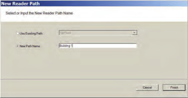
To create a new segment item folder
1 Right click on the parent folder and select New Path from the drop down list.
The New Reader Path dialog box opens.
Figure 54 Defining a New Reader Path
2 Select New Path Name and enter the name.
3 Select Finish. The new path folder is added to the Segment Tree. Repeat the
process to create the folders needed to define your Segment Tree. Figure 55
shows a Segment Tree with several added folders and sub-folders.
Select New
Path Name and
enter a name
81
Figure 55 Folders and Sub-Folders in the Segment Tree
Moving Portal Gateways within the Segment Tree
Once you have created the Segment Tree with folders and sub-folders, you can
move Portal Gateways into the appropriate folders.
Click on the Portals tab. Select the desired Portal Gateway from within the Seg-
ment Tree and drag it to the desired folder.
82
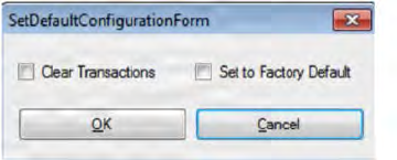
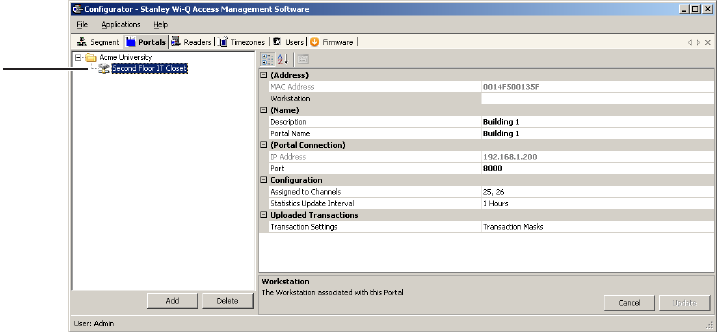
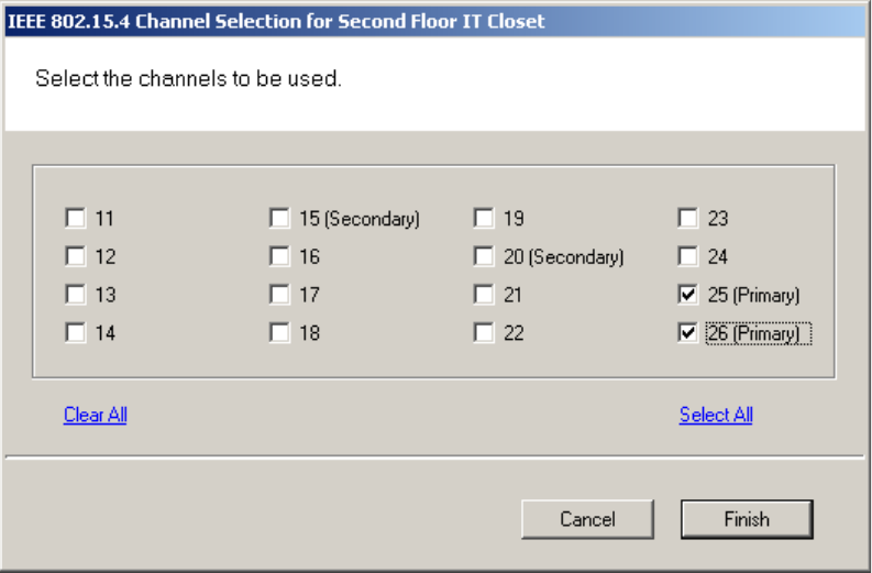
Assign Portal Channels
Portal Gateways default to All Channels; however, you can assign specific chan-
nels if needed. For example, if you have configured a new wireless component to
operate on channel 17, you will want to disable channel 17 in the Portal channel
configuration.
To assign Portal channels
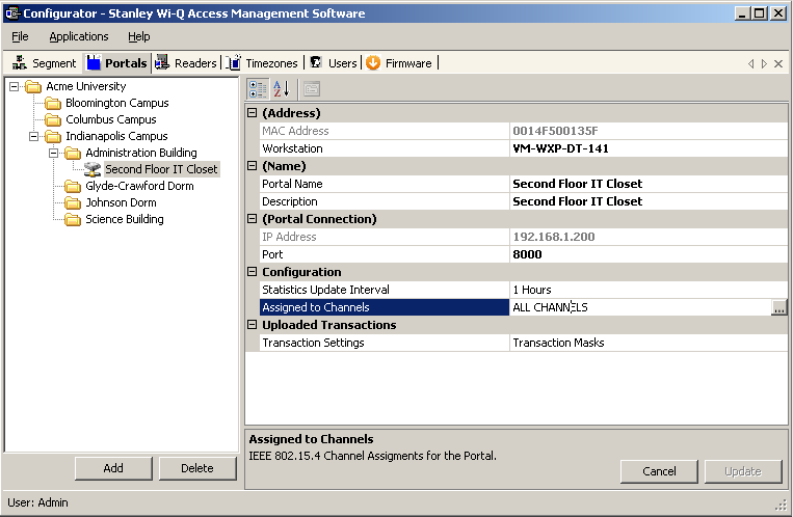
1 Click on the Portal tab, and select the desired Portal from the Segment Tree. Click-
ing on a Portal will display Portal properties on the left.
Figure 56 Portal Properties
2 Under the Configuration category, click in the Assigned to Channels field. The
ellipsis button appears at the far right of the field. Click the ellipsis button to
open the Channel Selection window.
83
Figure 57 Portal Channel Selection
3 Enable or disable channels as needed (at least one channel must be selected).
4 Click Finish to save your settings.
84
Sign on and Configure Controllers (Task 10)
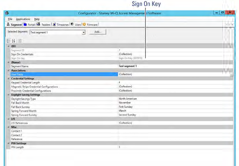
Each segment created in AMS is assigned a discrete Sign On Key number. Select
a segment and you will find this number in the ID Category of the Configurator
module’s Segment Tab.
Figure 58 Signing on readers from the Segment tab
If your segment uses Controllers with keypads, you must enter this number at
each Controller to establish connection between the Controllers and the Portals,
and ultimately to a segment in the software. If you use card readers, you can
create a sign-on card to use at each reader. Either way, you must sign on each
Controller in the system to register them in the database and ultimately establish
communication with the software.
Note Readers associated with Single Door Controllers are configured, signed on, and
monitored in AMS exactly like any other networked keypad Controller in the
system.
85
Signing on Keypad Controllers
If your segment uses keypad Controllers, use the following steps, in sequence, to
register each Controller in the system. Once this is done, the readers will appear
in the <New Segment Items> folder, viewable in the Readers tab Segment Tree.
Note The following sequence is timed. Be sure to have your segment sign on key ready
to enter at the appropriate time.
1 At a keypad Controller, press the following number sequence on the keypad:
5678# (Wi-Q) or 5678 (Omnilock and WAC). The green light will flash three
times.
2 Within five or six seconds, begin to enter the six-digit segment sign on key
number, followed by #. You will have about five seconds to enter each number.
The sequence will time out if more than five seconds elapses between num-
bers.
3 Once the key number is completed, the reader begins to alternately flash green
and red to signify that it is searching for Portal Gateways in range. If the se-
quence was completed successfully, three green flashes indicate the Controller
has accepted the sign on key.
4 If you see three red flashes, the Controller has not accepted the number or you
have exceeded the time limit. Begin again at step two, and continue until you
receive three green flashes.
Note Once a Controller has been signed on, all sign-on functionality is disabled unless it
is deep-reset.
Signing on Card Readers
If your segment uses card readers, you may want to register one of your cards
with a segment credential number. This card will be used to sign on card readers
to the system. You can register a separate card and hold it specifically for this
purpose, or register one that belongs to a user such as the Administrator’s card.
Once this is done, you will use the card to sign on each reader in the system.
86
To register a card with a segment credential
1 In the Configurator’s Segment tab, select the segment to which the readers
belong.
2 In the ID Category, click in the Sign On Credentials field and select the ellipsis
button at the far right of the field. The Segment Credentials Setup property
sheet opens.
Figure 59 Segment Credentials Setup
3 Select the type of card you will use. If your card type is not listed, select Add.
The Add Credential to Segment dialog box opens.
Figure 60 Add Credential to Segment
87
4 Select the card type from the drop-down list, in this case, Magnetic Card. The
Segment (Magnetic) Card Credential Number Setting dialog box opens.
Figure 61 MAG Card Settings
5 You can enter the card’s 16-digit credential number manually; or, you can scan
the card at a local scanning wedge, or select a reader where the card will be
scanned.
To Scan a card locally, select Card Reader and Select Scan. You will have about
30 seconds from the time you select Scan to actually scan the card through a
reader.
To Scan at a reader, select Reader and select the reader from the drop-down
list to scan at from the drop-down list, then select Scan. You will have about
30 seconds from the time you select Scan to actually scan the card through a
reader (this option is available only if the reader has been signed on).
6 Select Finish to save your settings and return to the Segment Credentials Setup
dialog box, or Cancel if you decide not to create the number. The number ap-
pears in the Credential Number category and the card is now registered. If you
will use a Prox card, see the following additional steps to complete registra-
tion.
88
Completing the Credential for a Prox card
1 Under the Proximity Card category, Enforce Expiration Date, select True or
False, depending on your preference. If you select true, you will need to reg-
ister a new card when the expiration date occurs. If False, the card will not
expire.
2 Under Proximity Card Type, select the type of encryption the card uses from
the dropdown menu.
3 Select Finish. Once this is done, you can use this card to sign on card readers.
To sign on card readers
1 At each card reader, scan the card you registered with the segment credential.
2 Once this is done, the readers will appear in the <New Segment Items> folder,
viewable in the Readers tab Segment Tree.
Note Once a reader has been signed on, all sign-on functionality is disabled, that is,
removed from the database. If you wish to use the reader in a different capacity,
that will require a new sign on. You will need to perform a reset to restore its sign
on capability.
89
Adding Controllers to the Segment Tree
Within 10 to 15 seconds after you sign on a controller, it will appear in the Configu-
rator <New Segment Items> folder, viewable in the Readers tab. The folder will
appear in red to indicate that it has received new Controllers. See Figure 62.
Figure 62 <New Segment Items>
You can move new Controllers into sub-folders within the Segment Tree by drag-
ging them to the desired location. When all new Controllers have been assigned to
segment folders, the <New Segment Items> folder will be empty and the display
color will change from red to black. You can move segment sub-folders to differ-
ent locations in the tree and the Controllers within will move with them.
If you expand your segment by adding new Controllers, the new Controllers will
appear again in the red <New Segment Items> folder so that they can be assigned
a location in the Segment Tree.
When you first configure a Controller, you will have the option to configure a new
Controller or copy parameters from one that has already been configured.
90
Copying Reader Parameters
The Copy Reader Parameters feature is useful when you have more than one
reader that serves the same users and user groups or will be assigned a special
Timezone Group. This feature is available when you first bring a Controller from
the <New Segment Items> folder to the Segment Tree, and as a right-mouse-click
copy function. It makes sense then that if you are going to use this feature you will
want to configure the Users and User Groups before configuring the readers. See
“User Groups” on page 103 and “Adding Users to the Segment” on page 121 for
steps to create these parameters.
Configuring New Controllers
When you create a new Controller, its name is displayed in the Reader Proper-
ties section on the right, and it is automatically assigned to the Master Timezone.
Users, User Groups, and Timezone Groups will be available to the Controllers only
if they have already been configured. If not, you can configure the Controllers first
with default parameters and return to assign Users, User Groups and any Time-
zone Groups after they are created.
To configure a new Controller
1 Drag your Controller out of the <New Segment Items> folder and into your
desired sub-folder in the Segment Tree.
2 If you are configuring your first controller, select the Controller within the tree, and
the Reader Properties sheet will show on the right.
If you have signed on more than one Controller into your segment, a window
will open to ask if you would like to copy a configuration from another reader or
create a new configuration. See Figure 63.
If you select Copy Configuration from, you can choose a reader in the drop-
down list from which to copy configuration settings.
91
Figure 63 New Reader Configuration
When you have made your selection, click OK. If you are copying reader prop-
erties, a window will open asking if you would like to proceed. Click Yes to
proceed.
Field Category Definitions
The following is a list of Reader property field categories and their functions.
Reader Name
The Reader name displays automatically. You may change it by typing over the
default name.
Associations
If you have already configured User Groups and Users, you can assign them to the
readers now. If you have not yet configured these parameters, or don’t wish to do
it now, you can come back later to add these settings.
Configuration
Under the Configuration category, you can configure various reader settings, such
as default settings for Channels, Beacon Time, Operate and Shunt times, and add
delays depending on how the reader will be used.
Assigned to Channels — New readers default to All Channels; however, you can
assign specific channels if needed. For example, if an existing wireless compo-
nent operates on Channel 17, you will want to disable Channel 17 in the reader
channel configuration. See “Assigning Reader Channels”.
92
Beacon Time — The default Beacon Time for a reader is one minute; however,
you can manually input a different value anywhere from 10 seconds to 1 day. Keep
in mind, the more frequent the beacon time, the more battery power used.
Note For best results, it is recommended that beacon time be set to no lower than 1
minute.
Default Operate Time — The Default Operate time is three seconds. You can
manually enter a different value as needed.
Default Shunt Time — The Default Shunt Time is three seconds. You can manually
enter a different value as needed. This feature is useful for readers that will be
used to accommodate wheelchairs or other equipment that may need additional
time to get through the door before the alarm is triggered.
Operate Delay — This feature is useful during situations where, for example, a
guard may want a chance to visually confirm the identity of the user before ac-
cess is granted.
Shunt Delay — This feature is useful when the users accessing this reader typi-
cally need more time to pass through the door after it unlocks; such as, someone
in a wheelchair or someone who will move equipment through the doorway.
Statistics Update Interval — Manually enter the desired reader polling time.
Wiegand Device — Define if applicable.
First Card Unlock Authority — The reader requires authority to leave the door
unlocked when in an ‘unlock with ID’ access mode.
Card Formats Assignments — Assign card formats to the reader.
Assigning Reader Channels
Perform the following steps to assign reader channels.
1 In the Reader tab, select the desired reader within the Segment Tree.
2 In the Reader Properties sheet, under the Configuration category, click in the
Assigned to Channels field. The ellipsis button appears at the far right of the
field.
3 Click the ellipsis button to display the Channel Selection for the Reader.
93
Figure 64 Reader Channel Selection
4 Select your desired channels.
5 Click Finish to save your settings.
Note When changing a reader’s channels, ensure that it can connect to a Portal
Gateway on the same channel. For example: if a reader is changed to use only
Channel 17, the Portal’s channels must include Channel 17.
Reader Control
The Reader Control dropdown list corresponds to settings configured under the
Reader Control sub tab in the Timezones tab. See “Configuring Timezones” on
page 137 for more information.
94
Uploaded Transactions
Click on the Transaction Masks ellipsis button, the Configure Controller Transac-
tions dialog box will open.
Figure 65 Configure Controller Transactions
Here, you can determine what transaction types will show up in the Transactions
application. If you make a transaction a priority by checking the Priority checkbox,
it will come through immediately instead of waiting until the next beacon. If you
click on the Select All or Clear All buttons, a dialog box will open to ask if you want
to include Priorities as well. Select Yes or No.
95
96
This chapter will provide detailed information on configuring the AMS Software.
Now that Portal Gateways and Controllers have been added to and configured within
the software, you are ready to configure your segment even further. The first part of
this chapter will discuss the configurable items within the different categories of the
Segment tab.
Associations
In the Associations category of the Segment tab, you can select from a set of sup-
plied User Fields or add your own and create User Groups for your segment.
User Fields
Wi-Q AMS supplies you with a set of common User Fields which are available
in the User Tab when you start adding users. You are also supplied with a set of
additional User Fields and Categories that you can add to the system if needed. If
you do not find the fields and categories you need to fully define your user param-
eters, you can create your own and they will be available from the User Tab. When
you add and remove User Fields, the changes affect all segments in the system.
Adding Additional User Fields
1 In the Segment tab, click on User Fields and select the ellipsis button at the far
5 Configure AMS Software (Task 11)
97
right of the field. The User Field Management dialog box opens.
Figure 66 User Field Management
2 Click the Select Fields button at the bottom of the dialog box. The Select Seg-
ment User Fields dialog box opens. Additional pre-defined User Fields are listed
on the right.
98
Figure 67 Select Segment User Fields
3 To add one of these fields, select the checkbox next to the field and select
<<Add. The field is transferred to the User Fields in Facility box on the left.
Figure 68 User Fields in Facility
4 Select Finish. Once you add the field to a Segment, it will appear on the Users
99
Tab in the Configurator module. See the next few sections for steps to com-
plete this process.
Creating New User Fields
If the field you wish to add does not appear in the User Fields list on the right, you
can add one of your own. Once this is done, you can add it to an existing Category,
or create a new Category for the field. You can add any number of new fields and
new categories.
Perform the following steps to To create a New User Field.
1 In the Select Segment User Fields dialog box, select Add Field at the bottom of
the box. The Add, Remove, and Configure System User Fields dialog box opens.
Figure 69 Add, Remove and Configure System User Fields
2 Under Specifications, Category, select the category under which you wish the
new field to appear from the drop down list, for example, Statistics.
Note If the category you want is not available, you can also create your own category.
See “Adding a New User Fields Category” on page 101.
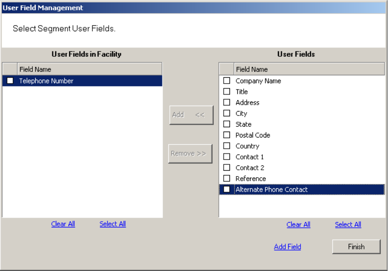
100
3 In the Field Name category on the right, type in a new name for the new field.
In the example, we used Alternate Phone Contact.
4 Select Update. When you click Finish, the Select Segment User Fields dialog
box shows that your new field is now available for selection.
Figure 70 User Field added to list
5 Select the Checkbox next to the field and click <<Add. The field is transferred
to the User Fields in Segment box on the left.
6 Select Finish. The new field is now added to the User Field Management dialog
box.