dormakaba USA SDC2K Wireless Electronic Lock User Manual Manual 3
Stanley Security Solutions, Inc. Wireless Electronic Lock Manual 3
Contents
Manual 3
201
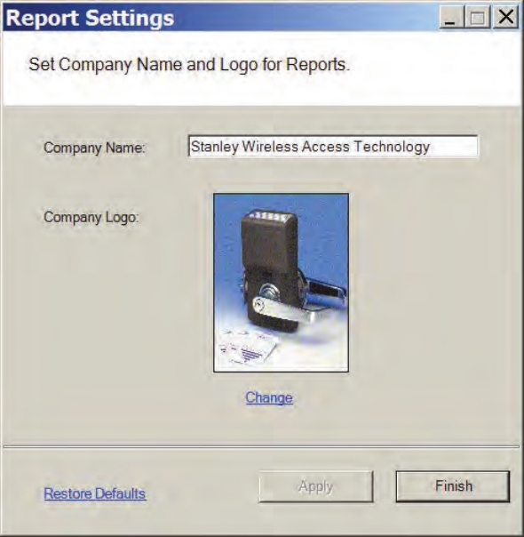
Configure Report Settings
You can include your company or organization name and logo with any report.
AMS supports both .bmp and .jpg image formats. Perform the following steps:
1 In the Segment box, select the Segment for which you wish to create the set-
ting.
2 Select Options>Report Settings. The Set Company Name and Logo for Reports
dialog box opens.
Figure 147 Setting up a company name for a report
3 In the Company Name field, type in the company name you wish to appear on
your reports.
4 Under Company logo, click the Change link. Use the Select Logo browser to
navigate to the file you wish to include.
5 Click Open. The file is now uploaded to the Reports settings.
6 Click Finish to save your settings and begin working with Reports.

202
Generating a Report
This section presents steps to create some example reports. Once you are famil-
iar with the basic operations, you will be able to create your own reports using the
selections available in Reports. First we’ll look at a Users of Readers report with
All Users selected. Then we’ll look at a filtered report using the options under the
Report Settings categories.
Note The Reports application won’t show much data until you have configured your
system added Users and User Groups, and begun collecting transactions. Once
this occurs, you can experiment with the options to get the reports that will be
most significant for your operation.
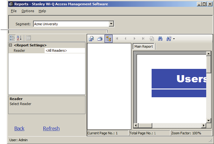
To Generate a Report
1 In the Reports main screen, under the User Reports box, click on Users of
Readers. Reports opens at the basic users of Readers Reports generator.
2 In the Segment box, select the Segment you wish to report on.
3 Available report settings are listed on the left, and the results are shown on the
right. For this particular report, the default will be <All Readers>.
Figure 148 Viewing System Reports
4 Use the scroll bars to view the data, use menu icons to export, print, scroll
through multi-paged reports, or use the Zoom tools to get a closer look.
5 If you have a large number of readers, Click the Toggle Group Tree icon and
203
highlight a specific reader to jump to its section in the report.
Figure 149 Toggle Group
6 Click Run Report (bottom left of screen) to return to the Report Generator
screen.
Generating Filtered Reports
The report generator defaults to print all records. For example, when you select
the Users of Readers report, report content displays users of all readers in the
system. You can filter the report to display the users of only one specific reader,
as in the following example.
Toggle group
button
204
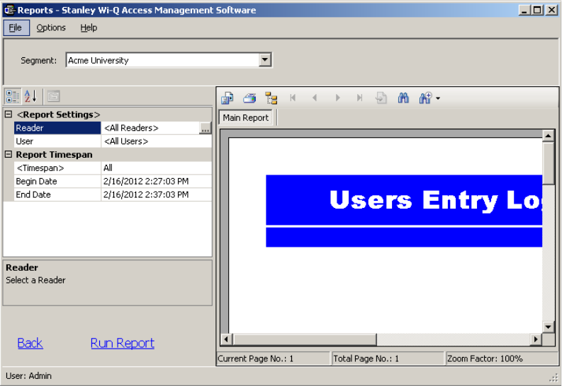
To create filtered report
1 In the Reports main screen, select the Segment you wish to report on.
2 Under the User Reports box, click on Users Entry Log. The report opens (Figure
155). In this report set up, more selections are available for this report than for
the Users of Readers report, including Reader, User, and Report Timespans.
You can use any or all of these selections to filter your report. Each report type
will have different selections available depending on the data available for the
report. The defaults are always All.
Figure 150 Users of Readers Report
3 To select a specific reader for this report, click on the Reader field’s ellipsis
button. The Select Reader dialog box opens.
4 Clear the All Readers box just below the drop-down list box.
5 Select the reader to filter from the drop-down list.
6 Click Finish. The report results will display data for only the reader you select-
ed.

205
Generating Larger Reports
The more records you include in your report, the longer the report will take to gen-
erate. During report generation, you can use other AMS applications; however,
you can generate only one report at a time in the Reports application. If you define
a report that will take more than 30 minutes to generate based on the records
included, the software will present the following message:
In the example, AMS detected that the defined report contains over 30,000 re-
cords and will take more than 30 minutes to generate. If this is acceptable, simply
select Yes and the report will be generated. Select No if this is an inconvenient
time to generate the report, or review your report definitions to see if you can fur-
ther filter the report and still get the information you need. When you select Yes,
the report begins to generate and AMS displays the Elapsed Time as the report
runs.
Printing and Exporting Reports
Once you are satisfied with your report, you can print to a local or networked
printer, or export the report in several formats. Your results will be determined
by the options you select and how you wish to use the data. For example if you
export to a Microsoft Excel file, you may get a different formatting result than if
you export to an Adobe Acrobat file or print directly from AMS. However, you may
wish to export to an Excel file and use the data in another format. The following
example was printed from an Adobe Acrobat .pdf file exported from Reports. It
retains all the formatting as displayed in Reports.

206
Figure 151 Sample report file
To print a report
1 Create the report using the features described in the previous sections.
2 Click the Printer icon in the menu bar.
3 Navigate to the printer you wish to use.
4 Print using the appropriate actions for the chosen printer.
207
To export a report
1 Create the report using the features described in the previous sections.
2 In the menu bar, click the Export Report option.
3 In the Export Report dialog box, select a format type from the drop-down list.
The available types are:
Crystal Reports (*.rpt)
Adobe Acrobat (*.pdf)
Microsoft Excel (*.xls)
Microsoft Excel Data Only (*.xls)
Microsoft Word (*.doc)
Rich Test Format (*.rtf)
4 Navigate to the location you wish to export to.
5 Enter a filename for the file.
6 Click Save.
Now you can use the report in any manner you wish, depending on the format
exported.
208
7 Advanced Troubleshooting
This section provides an overview on the Portal Gateway status webpage. You
can access the status webpage for a specific Portal Gateway in one of two ways:
Inside the Portal Configuration Module, select Scan. Locate the desired Portal
in the list and click on its hyperlink. See Figure 43 on page 68.
Type your desired Portal’s IP address directly into your internet browser.
Your browser will display the status of your Portal Gateway and associated de-
vices. See Figure 157.

209
Figure 157 Portal Gateway Status Webpage
The Portal Gateway Status webpage provides the following information:
1 Last System Boot
Last time Portal Gateway was reset or rebooted.
2 Radio and Channel
Shows the channel associated with each radio in the Portal.
3 Associated Devices List
Shows which devices are associated with the Portal.
4 MAC Address
Column shows the MAC Address of each associated device.
5 Associate Time
Column shows the time that the Controller last associated with the Portal.
6 Beacon
Column shows the time of the last Controller beacon.
7 %
Column shows progress percentage of pending operations.
1
2
3
45 6 7 8 9 10 11 12 13
Status Page Generated 03/06/2012-16:18:39
Last System Boot 03/05/2012-17:02:45
Portal MAC 0014f5201731
Radio 1 at channel 20 PAN_id 6401
Radio 4 at channel 15 PAN_id 6402
Associated Devices 15 Maximum allowed 64
MAC ADDRESS Stat Associate Time Beacon % F/W Rev R PG_RSS RDR_RSS - FLAGS PEND
01 0014f5404e9e 0000 03/05/12-17:04:10 16:18:26 none 003.000.038 1 -28 -19 - 000300043 -|--------|-
02 0014f5403854 0000 03/05/12-11:41:38 16:18:30 none 003.000.038 1 -28 -19 - 000300043 -|--------|-
03 0014f54010d9 0000 03/05/12-17:04:19 16:17:07 none 003.000.038 4 -19 -19 - 000300043 -|--------|-
04 0014f5401241 0000 03/05/12-17:04:19 16:18:10 none 003.000.038 4 -19 -27 - 000300043 -|--------|-
05 0014f5201abc 0000 03/06/12-11:26:31 16:17:56 none 003.000.038 1 -28 -28 - 000300043 -|--------|-
06 0014f540127e 0000 03/05/12-17:04:24 16:18:08 none 003.000.038 1 -23 -28 - 000300043 -|--------|-
07 0014f5404ee1 0000 03/05/12-17:04:27 16:17:39 none 003.000.038 1 -28 -19 - 000300043 -|--------|-
08 0014f52001d0 0000 03/05/12-17:04:38 16:18:15 none 003.000.038 1 -22 -26 - 000300043 -|--------|-
09 0014f54012c1 0000 03/05/12-17:04:44 16:18:27 none 003.000.038 4 -49 -26 - 000300043 -|--------|-
10 0014f5400003 0000 03/05/12-17:04:48 16:17:40 none 003.000.038 1 -27 -38 - 000300043 -|--------|-
11 0014f5400002 0000 03/05/12-17:04:53 16:18:32 none 003.000.038 1 -28 -28 - 000300043 -|--------|S
12 0014f54010ca 0002 03/06/12-11:28:04 16:16:46 45 003.000.038 1 -28 -19 - 000300043 U|S-------|-
13 0014f520173d 0000 03/05/12-18:11:32 16:18:29 none 003.000.038 1 -19 -36 - 000300043 -|--------|-
14 0014f5401301 0000 03/05/12-17:05:09 16:17:31 none 003.000.038 1 -28 -19 - 000300043 -|--------|-
15 0014f540126d 0000 03/05/12-17:05:26 16:18:31 none 003.000.038 1 -29 -25 - 000300043 -|--------|-
210
8 F/W Rev
Column shows the firmware version number of associated Controller.
9 R
Column shows which radio the Controller is connecting to in the Portal Gate-
way. Radio 1 is on the right side of the Portal. Radio 4 is on the left side of the
Portal.
10 PG_RSS
Column shows the signal strength of the Controller as received at the Portal.
This signal strength ranges from -18 (highest) to -91 (lowest).
11 RDR_RSS
Column shows the signal strength of the Portal as received at the Controller.
This signal strength ranges from -18 (highest) to -91 (lowest).
12 FLAGS
Column shows the current operational status of the associated device.
13 PEND
Column shows the abbreviation of the message currently in
operation.

211
Status Flags in the FLAGS Column
The following is a list of the bits in the FLAGS column and their corresponding
Portal Gateway status flags and definitions (Figure 157, item 12).
Note The typical Wi-Q and Omnilock device status code is 00030043. This is the example
used in the chart below.
Bit Portal Gateway Status Flag Definition
Right
END 3Bit 0 CONTROLLER_IS_ASSOCIATED Set when the Controller is first associated with
the Portal.
Bit 1 CONTROLLER_IS_VALID Set during association, after the Portal
receives a beacon from the Controller.
Bit 2 CONTROLLER_CONFIG_REQUIRED
Set during association, cleared by Portal
Communication Service after Controller
configuration.
Bit 3 CONTROLLER_ASSOC_PENDING_LIF Set during association to indicate that Portal
requires LIF (Lock Information Frame) data.
4Bit 4 CONTROLLER_BEGIN_TRANSMISSION Set when Portal first transmits data to the
Controller.
Bit 5 CONTROLLER_DEEP_RESET_PENDING Portal must disassociate Controller when it
receives the next beacon.
Bit 6 CONTROLLER_VALID_INTERVALS
Set when Controller interval assignment has
been received from the PC Communication
Service.
Bit 7 NOT USED
0Bit 8 CONTROLLER_RETRY_LIMIT_
EXCEEDED
Set when the retry limit on any command has
been hit; used to limit downloads to firmware
only.
Bit 9 NOT USED
Bit 10 NOT USED
Bit 11 NOT USED
0Bit 12 NOT USED
Bit 13 CONTROLLER_PREFERRED_PG_
ENABLED Set when Controller is locked to the Portal.
Bit 14 CONTROLLER_FIRMWARE_PENDING_
DN
Set when the firmware commit has been sent
to indicate that the disassociation is pending.
Bit 15 CONTROLLER_FIRMWARE_PENDING
Set when firmware update is scheduled for
the Controller, cleared when firmware commit
is sent.
3Bit 16 CONTROLLER_REPORT_TIME
_UPDATED
Set during association and when report time
is updated
Bit 17 CONTROLLER_LIF_IS_VALID Set when a LIF beacon is received
Left
END Bit 18-31 NOT USED

212
Update Flags in the PEND Column
Figure 158 is a section of the Associated Devices listed in Figure 157. Notice that items
11 and 12 have letters U and S in the PEND column. These letters are update flags,
and they stand for controller information that is being updated. The placement of the
update flags within the column denotes update status.
Figure 158 PEND Column Codes
The following is a list of the Update Flags that may be visible in PEND column.
Associated Devices 15 Maximum allowed 64
MAC ADDRESS Stat Associate Time Beacon % F/W Rev R PG_RSS RDR_RSS - FLAGS PEND
01
0014f5404e9e 0000 03/05/12-17:04:10 16:18:26 none 003.000.038 1 -28 -19 - 000300043
-|--------|-
11
0014f5400002 0000 03/05/12-17:04:53 16:18:32 none 003.000.038 1 -28 -28 - 000300043
-|--------|S
12
0014f54010ca 0002 03/06/12-11:28:04 16:16:46 45 003.000.038 1 -28 -19 - 000300043
U|S-------|-
13
0014f520173d 0000 03/05/12-18:11:32 16:18:29 none 003.000.038 1 -19 -36 - 000300043
-|--------|-
14
0014f5401301 0000 03/05/12-17:05:09 16:17:31 none 003.000.038 1 -28 -19 - 000300043
-|--------|-
15
0014f540126d 0000 03/05/12-17:05:26 16:18:31 none 003.000.038 1 -29 -25 - 000300043
-|--------|-
SSegment (PIN length, DST times)
CCard Formats
LController configuration (beacon time, channels, transaction masks, etc.)
UUsers
TTImezone Intervals
IWAC I/O
FFirmware
PPing (missing LIF data after association or update)

213
Figure 159 shows the significance of update flag placement between the dividing
lines in each entry of the PEND column.
Figure 159 Update Flag Placement in PEND Column
Item 11 in Figure 158 shows that the Controller’s Segment download is complete
pending LIF verification.
Item 12 in Figure 158 shows that the Controller’s Users are currently downloading,
with 45% complete, and the Controller’s segment update is pending.
Note Only one update flag will be positioned at the left or right, but it is possible for
more than one flag at a time to be in the center of an entry in the PEND column.
Left Center Right
–|– – – – – – – –|–
Currently
downloading
Pending
updates
Download complete
pending LIF verification
214
A Glossary
10Base-T The most common Ethernet wiring standard.
access level An access control relationship made between a
controller or controllers and a time zone or time
zones. An access level is assigned to a badge
ID for the purpose of granting access through a
controller or controllers during a specified time.
access panel A circuit board with on-board memory that is
responsible for making most of the decisions in an
access control system.
activation/deactivation date The date that a credential becomes active or
expires.
antipassback A configuration limiting the ability of consecutive
uses for a credential at a reader. Usually,
configured with readers installed on both the
secure and non-secure side of an opening. Once
a credential has been used in a reader to gain
access on one side of the opening, the credential
cannot be used in the same reader until the
credential is used to gain access to a reader from
215
the opposite side of the opening.
APB exempt Antipassback exempt. The cardholder with this
privilege is exempt from antipassback rules.
badge The credential or token that carries a cardholder’s
data.
badge ID Part of the access control information that is
encoded to a token. This information, usually
numerical, is unique to a particular credential
holder.
card format The way that data is arranged and ordered on the
card.
cardholder An individual who is issued a particular credential.
chassis type The designation that defines the physical lock
type. Three types exist: cylindrical, mortise, or exit
hardware. See those terms for more information.
common door A configuration setting that allows for the
allocation of duplicate badge ID ranges in separate
offline locks.
communication port The connector on the bottom of a Lock that allows
the lock to be connected to a reader.
communication server The server application designed to provide
network services to access panels, controllers,
PCs and PDAs.
credential A physical token, usually a card or fob, encoded
with access control information.
cylindrical Lock chassis that installs into a circular bore in the
door.
deadbolt override The ability for an authorized credential to retract
both the spring latch and the deadbolt when the
deadbolt is engaged
directional antenna An antenna type optimized to focus signal from
point-to-point over longer distances and through
obstacles.
216
dual access The requirement for the presentation of two
separate, authorized credentials in order to gain
entry through an access controlled opening.
ethernet The most common networking standard in the
world, formally known as IEEE 802.3.
exit hardware Lock chassis type that supports exit hardware trim
lock.
extended unlock The extra period of time the lock will unlock when
an authorized credential with extended unlock
privileges is presented.
guest A feature that enables you to add and delete
cardholders to and from a lock without having to
go out to a lock to reprogram it.
Host The computer on which Wi-Q AMS software is
installed and set up to manage Portal Gateways
and readers on the network.
IP address The numeric address (like 192.168.1.1) that
identifies each device in a TCP/IP network.
input A hardware connection point used for status
reporting of a particular sensor.
intelligent system controller (ISC) See access panel.
I/O device A device, such as an alarm or parking gate that can
be configured to operate on the network using a
Wireless Access Controller.
issue code Part of the access control information contained
on a credential that allows reuse of the badge
ID when a credential is lost, damaged, or stolen.
Usually one or two digits in length, this code
increments forward when creating a new
credential. Access is granted only when the badge
ID and the issue code match the current database
information.
MAC address The Media Access Control number (MAC).
A unique, 12-digit number assigned by the
217
manufacturer of a network device.
mortise A lock chassis that installs into a mortised cavity
in the edge of a door.
omni-directional antenna An antenna type optimized to provide signal
coverage in all directions.
packet A discrete chunk of data, being transferred on a
TCP/IP or other addressable network.
passage mode The ability to double present an authorized
credential within the strike time to unlock an
opening. The lock is returned to its original status
by a second, double presentation of an authorized
credential.
portal gateway The Portal Gateway is a wireless device
connected to the Host computer through a secure
connection to transfer data signals from Wireless
Controller locks to and from the Host computer.
request to exit A sensor usually installed on the non-secure side
of the door that will mask the door position switch
upon activation.
segment code Part of the access control information that can be
encoded to a credential. This information, usually
numerical, is unique to a group of credentials.
Usually this feature is used to authenticate a
credential to a particular organization.
sign-on key Number generated within AMS to establish the
connection between the readers and the Portals,
and ultimately to a segment in the software.
site survey kit The Wi-Q Technology Site Survey Kit tool used
to determine optimum Portal Gateway location to
verify signal strength before permanently installing
the hardware.
time interval A specific range of time, which corresponds to a
particular day or days of the week. A time zone can
be comprised of several, individual intervals.
218
time zone A defined range of time for assignment to various
access control activities. A time zone may be
applied to a reader or readers when creating an
access level, to a reader to change the mode of
operation, to a relay to activate and deactivate, to
an input to mask and unmask, and a host of other
operations.
unlock duration The time that the lock momentarily unlocks.
use limit A configuration limiting a credential to a defined
number of uses.
Web Interface The software program that allows setup and
communication between the Portal Gateway and
the Host Computer.
Wi-Q Technology Provides efficient, online access control decisions
at the door.
Wireless Access Controller Wireless Access Controller provides additional
capability to connect stand-alone controllers and
locks.
219
wireless reader lock The wireless reader lock controls user access at
the door and grants user requests according to
how they are configured in the software.
220
B Lock installation

1
Planning the installation
BEST ACCESS SYSTEMS
a Product Group of Stanley Security Solutions, Inc.
Contents
These installation instructions describe how to install your
93KQ Cylindrical Lock. Topics covered include:
Planning the installation
............................................... 1
Preparing the door and door jamb
..............................2
Installing the lock
...........................................................7
Completing the installation
........................................13
Patents
Products covered by one or more of the following patents:
5,590,555 5,794,472 5,083,122 6,720,861
Site survey
Use the following survey to record information about the
installation site. You need this information to determine
how to prepare the door for the lock.
Door information
Door handing and bevel:
❑Left hand (LH)
❑Left hand, reverse bevel (LHRB)
❑Right hand (RH)
❑Right hand, reverse bevel (RHRB)
Door thickness: inches (1 3/4″ to 2 1/4″)
Environment information
Ambient temperature:
❑Is within specifications. See the tables below.
This product meets the following Locked Door Outdoor
test requirements for ANSI/BHMA 156.25:
This product meets the following Full Indoor test require-
ments for ANSI/BHMA 156.25:
Side of door Range
Outside –31°F to +151°F (–35°C
to +66°C)
Side of door Range
Inside and out-
side
+32°F to +120°F (0°C to +49°C)
Components checklist
Use the following checklist to make sure that you have the
items necessary to install your Electronic Wireless Cylin-
drical Lock.
Components provided in the box:
❑Chassis with outside lever and outside rose liner
assembly
❑Top and bottom inside covers
❑Fire plate
❑Battery holder with batteries
❑Inside rose liner
❑Outside escutcheon assembly
❑Inside lever
❑Throw member package
❑Latch
❑Hub washers
❑Trim hole insert package
❑Plastic bushing package
❑Escutcheon screw package
❑Door status switch assembly
❑Strike package
❑Bar code ID sticker (for your records)
❑Installation template and instructions
Other components:
❑Core and control key
❑Temporary operator card
Special tools checklist
Use the following checklist to make sure that you have the
special tools necessary to install your Electronic Wireless
Cylindrical Lock.
❑KD303 Drill jig
❑T20 TORX® bit driver
❑KD325 Strike plate locating pin
❑KD315 Faceplate marking chisel
Installation Instructions for
Wi-Q™ Technology 9KQ Cylindrical Locks
Installation Instructions for Wi-Q™ Technology 9KQ Cylindrical Locks
2
Preparing the door and door jamb
BEST ACCESS SYSTEMS
a Product Group of Stanley Security Solutions, Inc.
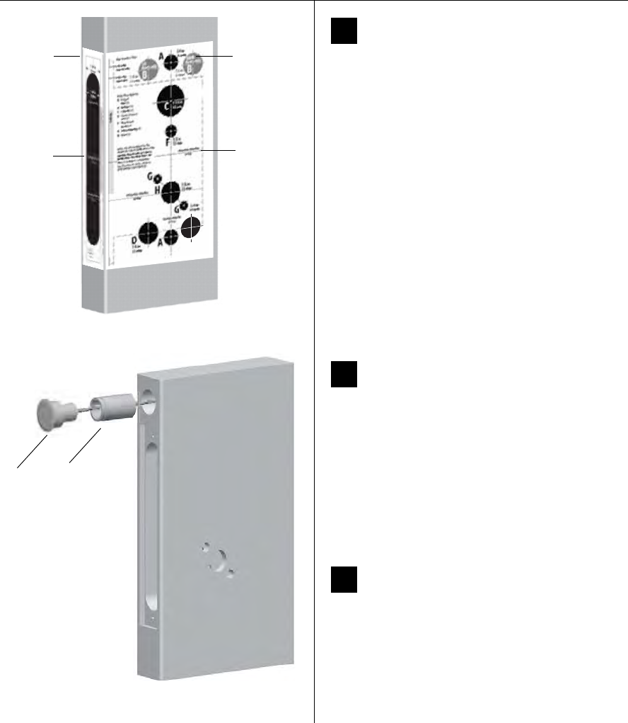
1Position template and mark drill points
Note: If the door is a fabricated hollow metal door,
determine whether it is properly reinforced to support
the lock. If door reinforcement is not adequate, consult
the door manufacturer for information on proper rein-
forcement. For dimensions for preparing metal doors,
see the
Q01 and G02 Templates—Installation Specifi-
cations for 93KQ Cylindrical Locks
.
Note: If the door is a LH or RH door, mark the inside of
the door. If the door is a LHRB or RHRB door, mark the
outside of the door.
For uncut doors and frames
1 Measure and mark the horizontal centerline of the
lever (the centerline for the chassis hole) on the door
and door jamb. Mark the vertical centerline of the door
edge.
Note: The recommended height from the floor to the
centerline of the crossbore or chassis hole is 38”
.
2 Fold the
Q05 Template—Installation Template for
93KQ Cylindrical Locks
on the dashed line and carefully
place it in position on the high side of the door bevel.
Note: For steel frame applications, align the template’s
horizontal centerline for the latch with the horizontal
centerline of the frame’s strike preparation.
3 Tape the template to the door.
4 Center punch the necessary drill points. Refer to the
instructions on the template.
For doors with standard cylindrical preparation
1 Fold the
Q05 Template—Installation Template for
93KQ Cylindrical Locks
on the dashed line. Looking
through the hole from the opposite side of the door,
align the template so that you see the template
outline of the 2 1/8″diameter chassis hole.
2 Tape the template to the door.
3 Center punch the necessary drill points. Refer to the
instructions on the template.
Figure 1 Positioning the template
Installation template
Centerline of lock
Installation Instructions for Wi-Q™ Technology 9KQ Cylindrical Locks
3
Installation Instructions for Wi-Q™ Technology 9KQ Cylindrical Locks
Preparing the door and door jamb
BEST ACCESS SYSTEMS
a Product Group of Stanley Security Solutions, Inc.
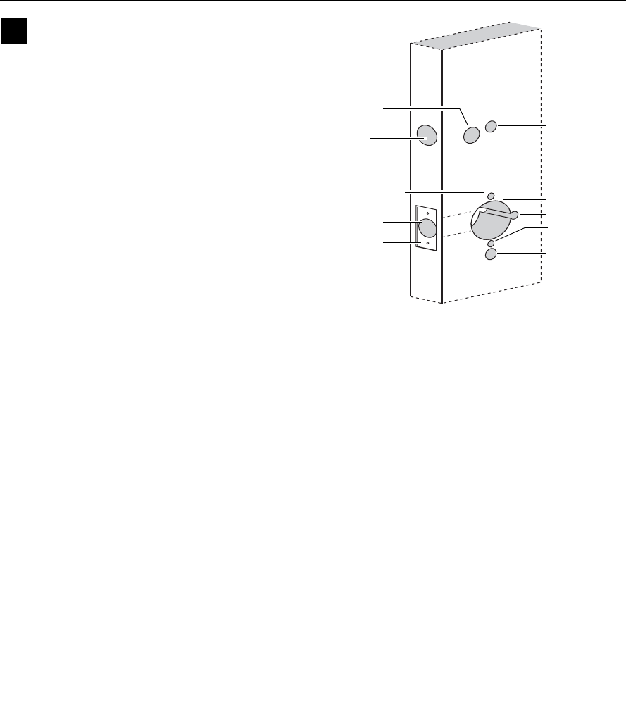
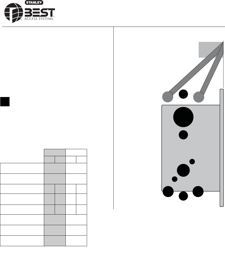
2Drill holes and mortise for latch face
1 Drill the holes listed below:
■upper and lower trim holes
◆5/8″ diameter
◆through door
■harness hole
◆3/4″ diameter
◆through door
■motor wire hole
◆7/16″ diameter
◆through door
◆before drilling chassis hole
■chassis hole
◆2 1/8″ diameter
◆through door
◆after drilling motor wire hole
■latch hole
◆1″ diameter
◆meets chassis hole
■door status switch hole
◆1″ diameter
◆meets harness hole
■anti-rotational hole, see “Use drill jig to drill
through-bolt holes” on page 5.
◆5/16” diameter
◆through door
Note 1:
To locate the center of a hole on the opposite
side of the door, drill a pilot hole completely through
the door.
Note 2:
For holes through the door, it is best to drill
halfway from each side of the door to prevent the door
from splintering.
2 Mortise the edge of the door to fit the latch face.
3 Drill the holes for the screws used to install the latch.
Figure 2 Drilling holes and mortising for the latch face
Latch hole
Upper trim hole
Harness
hole
Motor wire hole
Chassis hole
Lower trim hole
Latch face
mortise
Inside of door
Door
status
switch hole
Anti-rotational
hole
Anti-rotational
hole
Installation Instructions for Wi-Q™ Technology 9KQ Cylindrical Locks
3
Installation Instructions for Wi-Q™ Technology 9KQ Cylindrical Locks
Preparing the door and door jamb
BEST ACCESS SYSTEMS
a Product Group of Stanley Security Solutions, Inc.
2Drill holes and mortise for latch face
1 Drill the holes listed below:
■upper and lower trim holes
◆5/8″ diameter
◆through door
■harness hole
◆3/4″ diameter
◆through door
■motor wire hole
◆7/16″ diameter
◆through door
◆before drilling chassis hole
■chassis hole
◆2 1/8″ diameter
◆through door
◆after drilling motor wire hole
■latch hole
◆1″ diameter
◆meets chassis hole
■door status switch hole
◆1″ diameter
◆meets harness hole
■anti-rotational hole, see “Use drill jig to drill
through-bolt holes” on page 5.
◆5/16” diameter
◆through door
Note 1:
To locate the center of a hole on the opposite
side of the door, drill a pilot hole completely through
the door.
Note 2:
For holes through the door, it is best to drill
halfway from each side of the door to prevent the door
from splintering.
2 Mortise the edge of the door to fit the latch face.
3 Drill the holes for the screws used to install the latch.
Figure 2 Drilling holes and mortising for the latch face
Latch hole
Upper trim hole
Harness
hole
Motor wire hole
Chassis hole
Lower trim hole
Latch face
mortise
Inside of door
Door
status
switch hole
Anti-rotational
hole
Anti-rotational
hole
Installation Instructions for Wi-Q™ Technology 9KQ Cylindrical Locks
4
Preparing the door and door jamb
BEST ACCESS SYSTEMS
a Product Group of Stanley Security Solutions, Inc.
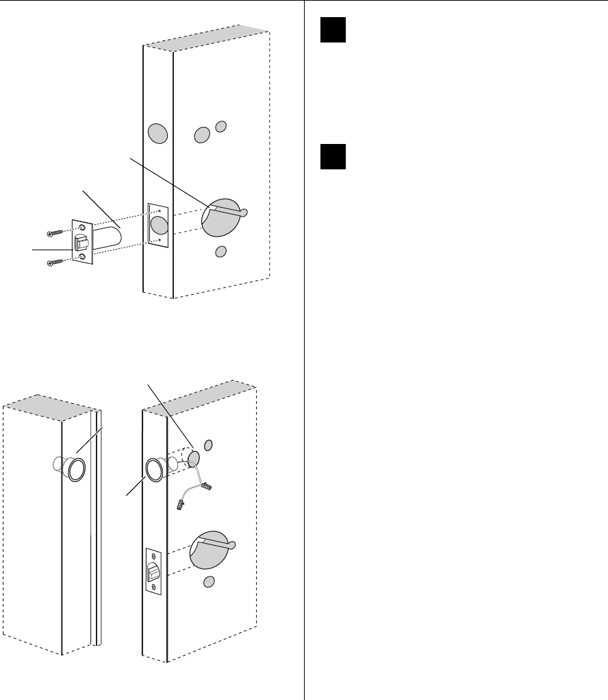
3Install latch
1 Install the latch in the door.
Note: The latch tube prongs should be centered and
should project into the chassis hole.
2 Check that the door swings freely.
4Install door status switch and magnet
1 On the door jamb, mark the drill point for the
1″diameter magnet hole. This hole should be directly
opposite the door status switch reader harness hole
when the door is closed.
2 Drill a 1″diameter hole for the magnet, at least 1 3/4″
deep.
3 Insert the magnet in the hole.
4 Insert the door status switch assembly into the door
status switch hole in the edge of the door, feeding the
connectors out the harness hole to the inside of the
door, as shown in Figure 4.
Figure 3 Installing the latch in the door
Latch
Location of latch
tube prongs
Chassis hole
Inside of door
Figure 4 Installing the door status switch and magnet
Magnet
Harness hole
Inside of door
Door
status
switch
Door jamb
Installation Instructions for Wi-Q™ Technology 9KQ Cylindrical Locks
5
Installation Instructions for Wi-Q™ Technology 9KQ Cylindrical Locks
Preparing the door and door jamb
BEST ACCESS SYSTEMS
a Product Group of Stanley Security Solutions, Inc.
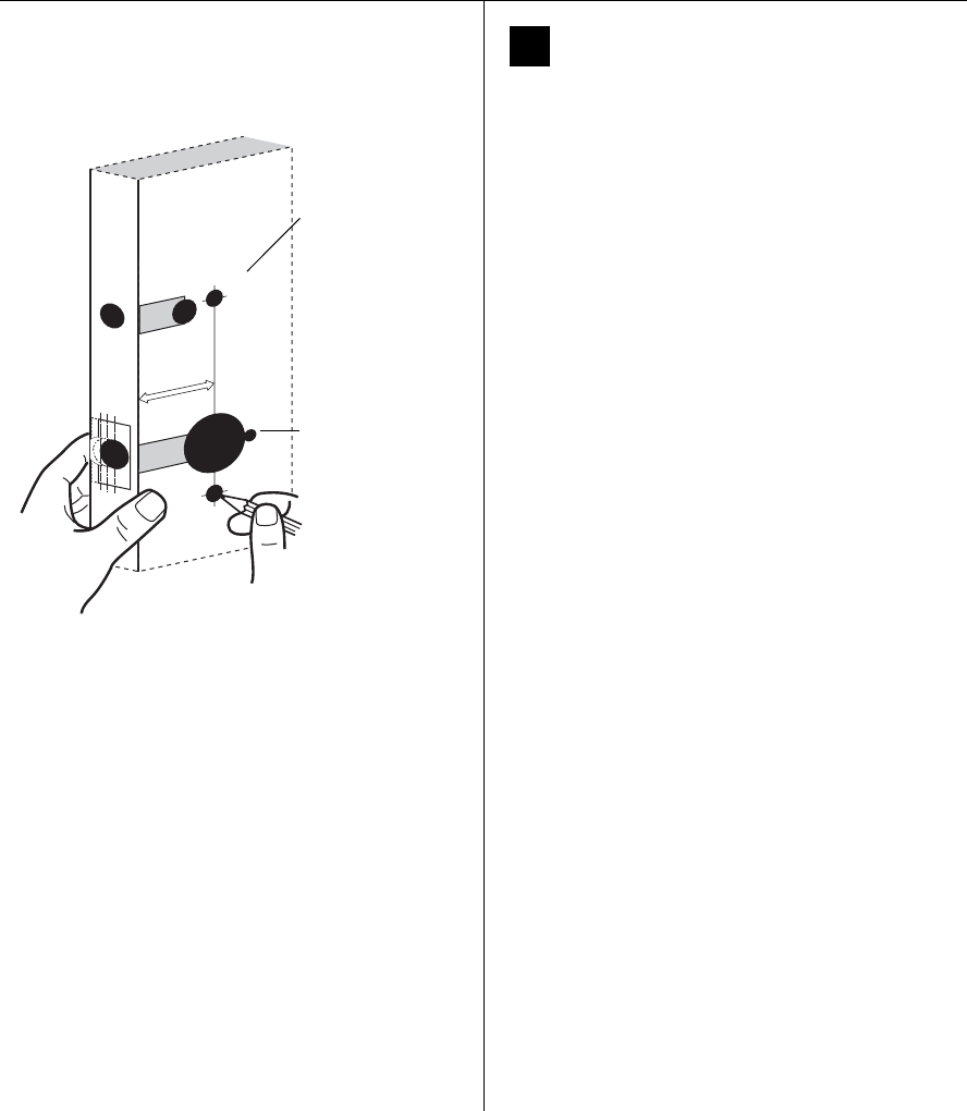
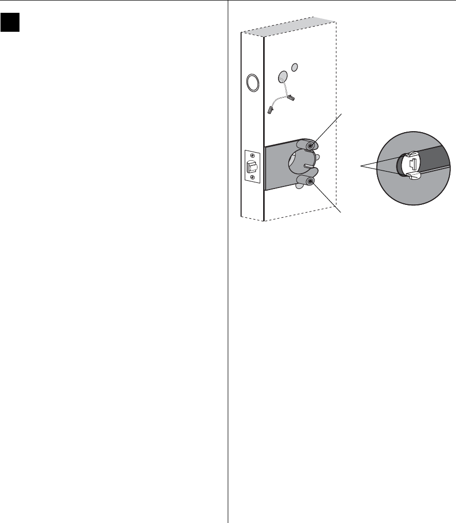
5Use drill jig to drill through-bolt holes
1 Press the drill jig (KD303) onto the door, engaging it
with the latch tube prongs (see the close-up in
Figure 5). Make sure the front edge of the jig is parallel
with the door edge.
2 Drill the through-bolt holes (5/16″diameter) halfway
into the door.
3 Turn over the drill jig and repeat steps 1 and 2 from the
opposite side of the door.
Note: Replace the drill jig after 10 door preparations.
Figure 5 Installing the drill jig and drilling the
through-bolt holes
Latch
tube
prongs
Drill upper through-bolt
hole.
Drill lower through-bolt hole.
Inside of door
Installation Instructions for Wi-Q™ Technology 9KQ Cylindrical Locks
6
Preparing the door and door jamb
BEST ACCESS SYSTEMS
a Product Group of Stanley Security Solutions, Inc.
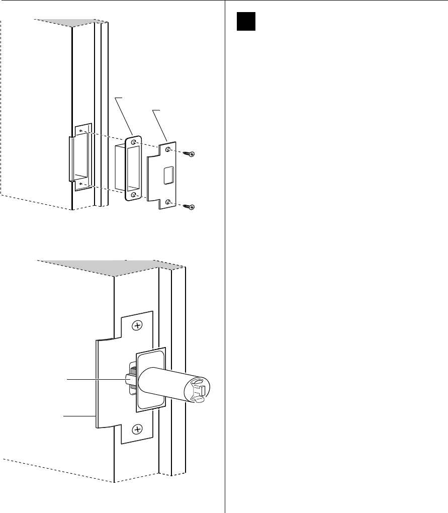
6Install strike box and strike plate
1 In alignment with the center of the latchbolt, mortise
the door jamb to fit the strike box and strike plate.
2 Drill the holes for the screws used to install the strike
box and strike plate.
3 Insert the strike box and secure the strike with the two
screws provided.
4 Check the position of the deadlocking plunger against
the strike plate.
Caution:
The deadlocking plunger of the latchbolt
must make contact with the strike plate, as shown
in Figure 6b. The plunger deadlocks the latchbolt
and helps prevents someone from forcing the
latch open when the door is closed.
Figure 6a Installing the strike box and strike plate
Strike box
Strike plate
Door jamb
Figure 6b Aligning the deadlocking plunger with the
strike plate
Strike plate
Deadlocking
plunger
Door jamb
Installation Instructions for Wi-Q™ Technology 9KQ Cylindrical Locks
7
Installation Instructions for Wi-Q™ Technology 9KQ Cylindrical Locks
Installing the lock
BEST ACCESS SYSTEMS
a Product Group of Stanley Security Solutions, Inc.
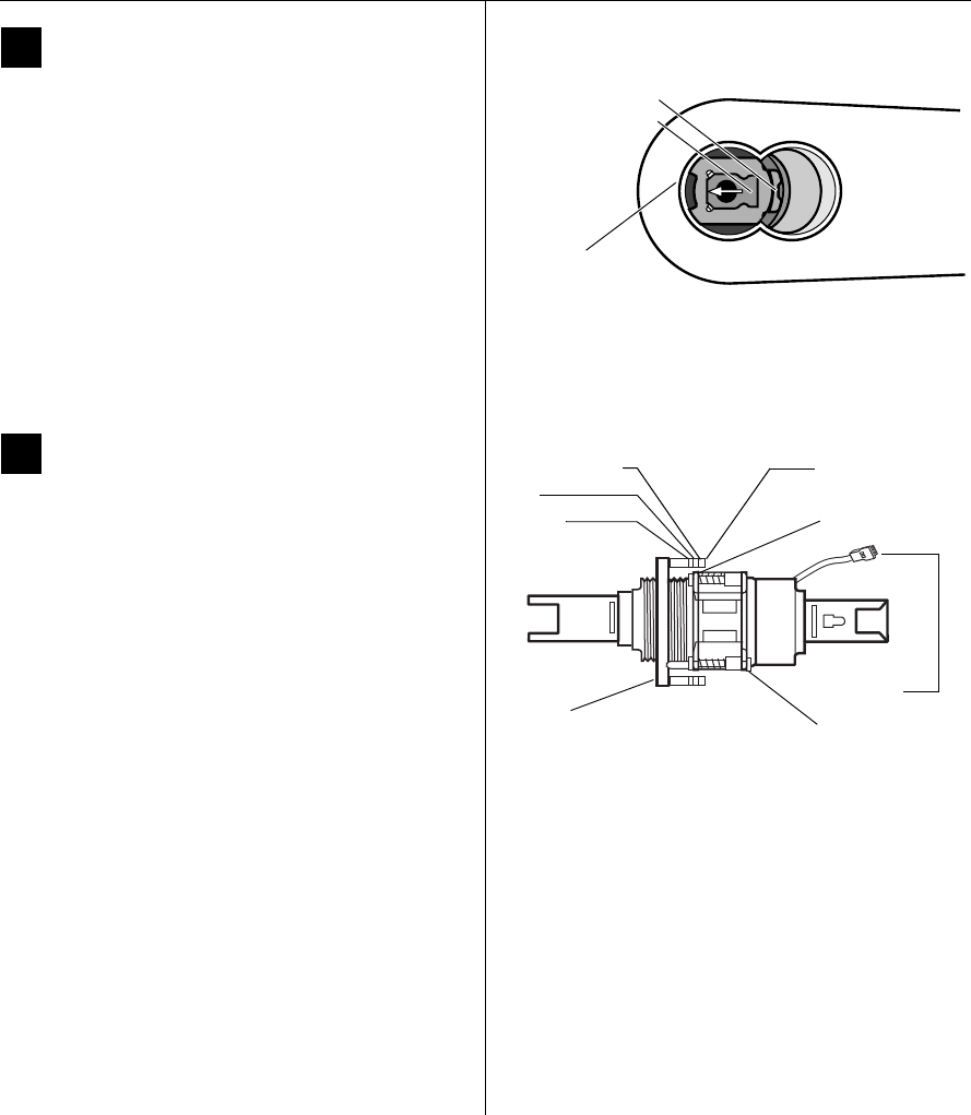
7Remove outside lever or knob
1 Insert the control key into the core and rotate the key
15 degrees to the right.
2 Insert a flat blade screwdriver into the figure-8 core
hole and into the lever.
3 Press the screwdriver blade in the direction of the
arrow in Figure 7.
Note: You cannot remove the lever if the screwdriver
blade is inserted too far past the keeper.
4 Slide the lever or knob off of the sleeve.
Caution:
Be careful that you do not disconnect the
lever keeper spring.
8Adjust for door thickness
1 Determine the door’s thickness.
2 Pull the rose locking pin and rotate the outside rose
liner until the proper groove on the through-bolt stud
lines up with the hub face.
Figure-8
core hole
Figure 7 Removing the outside lever
Insert screwdriver
blade here.
Lever keeper
Figure 8 Adjusting the rose liner for the door
thickness
1 3/4″
2″
2 1/4″ groove Through-
bolt stud
Hub face
Outside
rose liner Rose locking pin
Motor wire
Installation Instructions for Wi-Q™ Technology 9KQ Cylindrical Locks
8
Installing the lock
BEST ACCESS SYSTEMS
a Product Group of Stanley Security Solutions, Inc.
9Install lock chassis and engage
retractor in latch
From the outside of the door, insert the lock chassis
into the 2 1/8″ chassis hole, routing the motor wire
through the notch.
Caution:
Make sure that the latch tube prongs
engage the chassis frame and that the latch
tailpiece engages the retractor.
10 Install the trim hole insert, bushing,
and hub washer on outside of door
1 On the outside of the door, insert the trim hole insert
into the upper trim hole, as shown in Figure 10.
2 Insert the bushing into the harness hole.
3 Slide a hub washer over the chassis sleeve so it rests on
the hub.
Figure 9 Installing the lock chassis and engaging the
retractor in the latch
Latch tube
prong
Retractor
Latch
tailpiece
Chassis
Chassis frame
Latch tube
prong
Notch
Inside of door
Figure 10 Installing the outside trim hole insert,
bushing, and hub washer
Trim hole insert
Bushing
Hub washer
Hub
Outside of door
Installation Instructions for Wi-Q™ Technology 9KQ Cylindrical Locks
9
Installation Instructions for Wi-Q™ Technology 9KQ Cylindrical Locks
Installing the lock
BEST ACCESS SYSTEMS
a Product Group of Stanley Security Solutions, Inc.
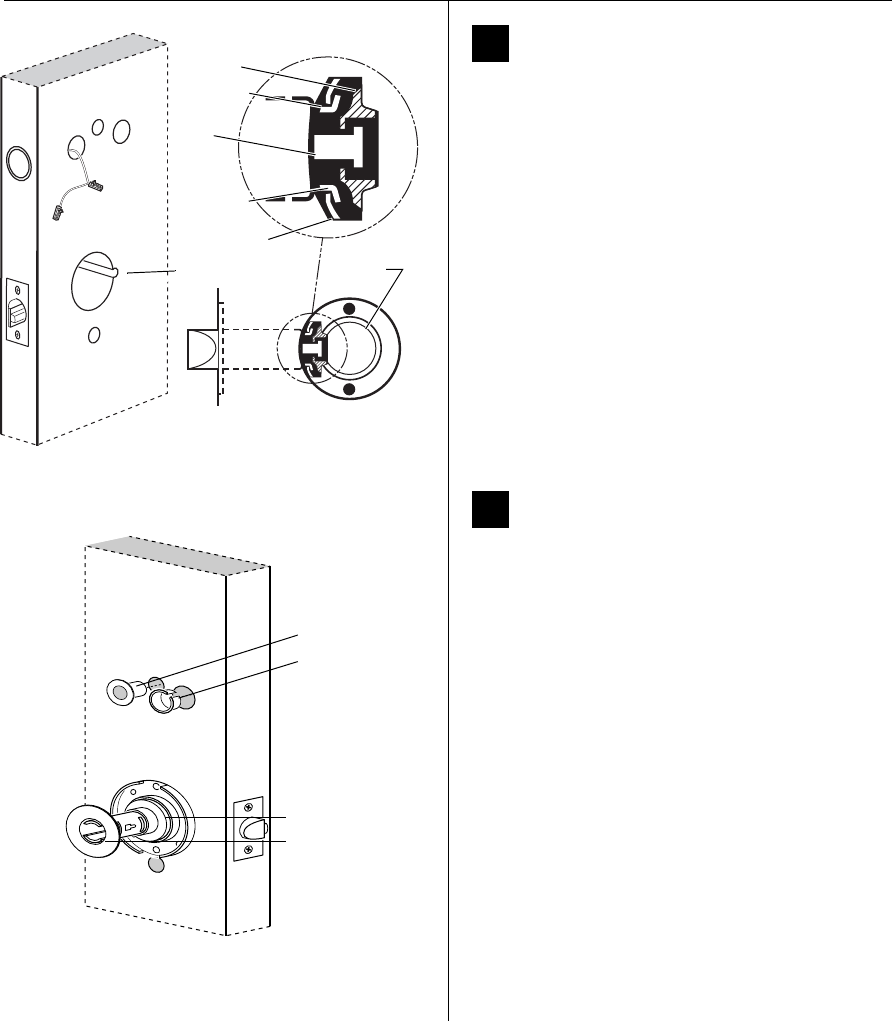
11 Install fire plate
Position the fire plate on the inside of the door so that the
chassis fits through the square opening in the fire plate, as
shown in Figure 11.
12 Install through-bolts and
inside rose liner
1 Place the inside rose liner on the chassis, aligning the
holes in the rose liner with the holes prepared in the
door, as shown in Figure 12.
Caution:
Make sure that the motor wire is pulled
toward the top of the fire plate and avoid routing
it over any surface that could damage the
sleeving or wire insulation.
2 Install the through-bolts through the rose liner and
door in the top and bottom holes.
Caution:
Make sure that there is clearance for the
motor wire between the rose liner and the door.
3 Tighten the rose liner to the door and fire plate with
the through-bolts.
4 Install the hub washer over the rose liner.
Figure 11 Installing the fire plate
Inside of door
Fire plate
Figure 12 Installing the through-bolts and rose liner
(9K shown)
Inside of door
Motor wire
Rose liner
with RQE
Hub
washer
Through-bolt
RQE
connector
Installation Instructions for Wi-Q™ Technology 9KQ Cylindrical Locks
10
Installing the lock
BEST ACCESS SYSTEMS
a Product Group of Stanley Security Solutions, Inc.
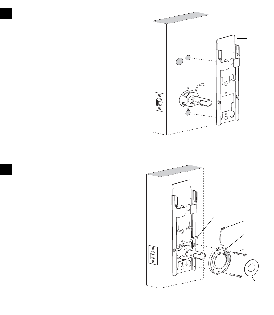
13 Route wire harness and position
outside escutcheon
1 From the outside of the door, feed the motor
connector, battery connector, door status switch, and
antenna wire, through the harness hole.
Caution:
When routing the connectors, make sure
the wire harness is not routed across any sharp
edges or over any surface that could damage its
sleeving or wire insulation.
2 On the inside of the door, insert the two countersunk
mounting screws into the holes at the top and bottom
of the fire plate.
3 Tighten the mounting screws until the fire plate is
securely mounted to the door.
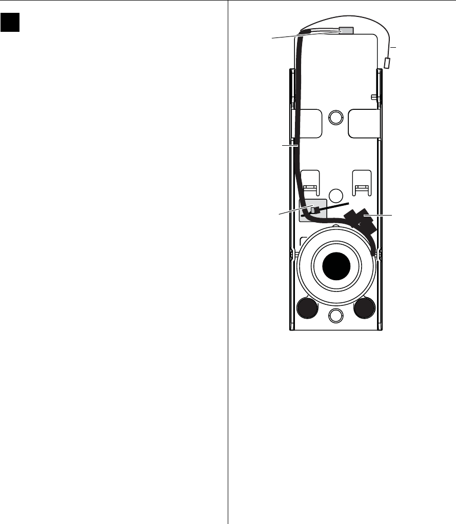
14 Route wires on fire plate
1 Route the motor connector wire, RQE connector, and
door status connector underneath the side tabs as
shown in Figure 14.
2 Route the battery connector and antenna wire above
the side tabs. See Figure 15 for additional detail.
Figure 13 Feeding the wire harness connectors through
the harness hole
Motor connector
Outside escutcheon
Outside of door
Battery connector
Door status
connector
Antenna wire
RQE connector
Harness hole
RQE connector
Figure 14 Routing the wires on the fire plate
Inside of door
Motor connector
Battery connector
Side tabs
Door
status
connector
Antenna wire
RQE connector
Door status
connector
Installation Instructions for Wi-Q™ Technology 9KQ Cylindrical Locks
11
Installation Instructions for Wi-Q™ Technology 9KQ Cylindrical Locks
Installing the lock
BEST ACCESS SYSTEMS
a Product Group of Stanley Security Solutions, Inc.
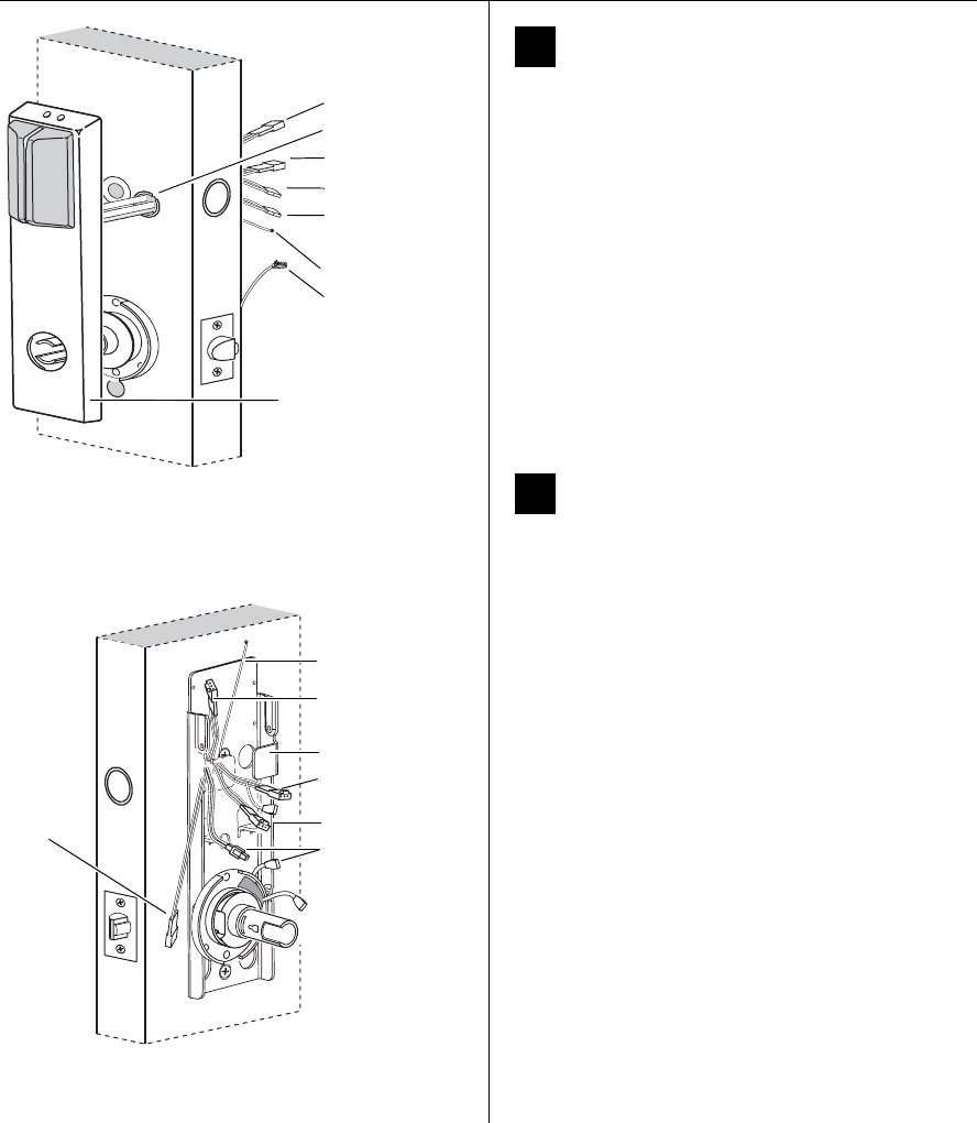
15 Connect motor wires, RQE, and
door status switch
1 From the inside of the door, make the following
connections:
◆Motor
◆RQE
◆Door status switch
2 Insert the plastic wire tie through the mounting clip
and secure the wires as shown in Figure 15. See Figure
15 for additional detail.
Caution:
When making the motor connection,
make sure:
◆there are no loose wire connections where the
wires are inserted into the connectors
◆the connectors are firmly mated.
Wire connection Color No. of
wires
No. of
pins
Motor Yellow-Gray 2 2
RQE Orange-Brown 2 3
Door status White 22
Figure 15 Routing the wires (view of the inside
escutcheon)
Route wire
harness on
the left side
of the fire
plate.
Mounting
clip and
wire tie
Dress wires so
that wire connec-
tors are mated
here. Use electric
tape to affix them
as needed.
Antenna wire
Battery
connector
Installation Instructions for Wi-Q™ Technology 9KQ Cylindrical Locks
12
Installing the lock
BEST ACCESS SYSTEMS
a Product Group of Stanley Security Solutions, Inc.
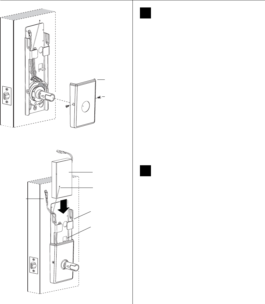
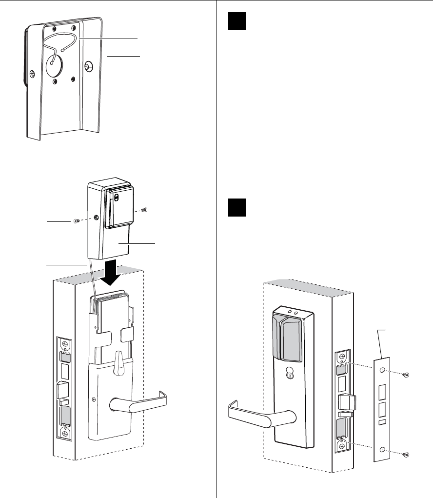
16 Install bottom cover
(inside escutcheon)
1 Making sure that the cover does not pinch the
wires, guide the bottom cover over the chassis onto
the fire plate.
2 Use two cover screws to secure the cover to the side of
the fire plate, as shown in Figure 16.
Note: Phillips Type 2 and T20 Torx options are available
for the cover mounting screws.
Caution:
Dress all wires away from possible pinch
points before putting the bottom cover in place.
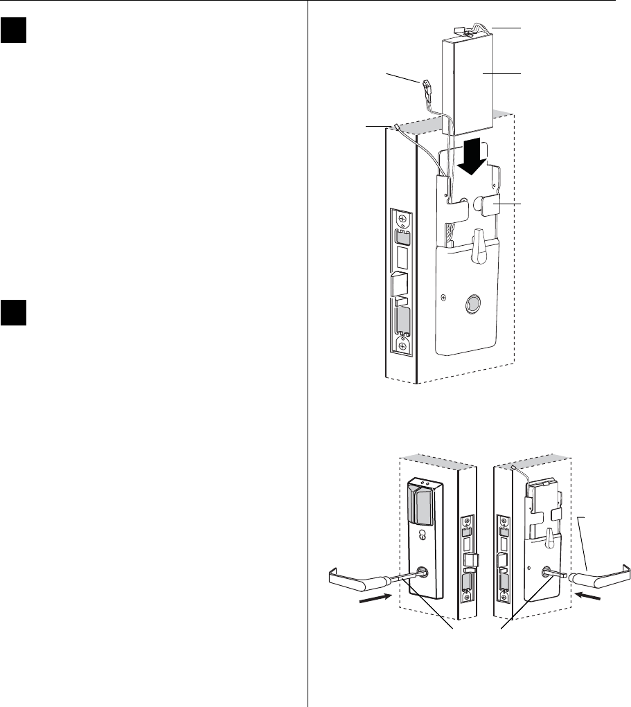
17 Install battery holder
1 Position the battery wires against the fire plate
side wall, as shown in Figure 17.
2 Slide the battery holder behind the fire plate side tabs
until it rests on the bent battery holding tabs.
Caution:
When routing the battery wires, make
sure the wires are not routed across any sharp
edges or over any surface that could damage their
sleeving or wire insulation.
3 Connect the battery holder to the battery connector
on the wire harness.
Caution:
When connecting the battery holder,
make sure:
◆there are no loose wire connections where the
wires are inserted into the connectors.
◆the connectors are firmly mated.
Figure 16 Installing the bottom cover
Inside of door
Cover
screws
Bottom
cover
Figure 17 Installing the battery holder, eight-cell
Inside of door
Battery holder
Battery wires
Battery holding
tabs
Fire plate side
tabs
Antenna
Installation Instructions for Wi-Q™ Technology 9KQ Cylindrical Locks
13
Installation Instructions for Wi-Q™ Technology 9KQ Cylindrical Locks
Completing the installation
BEST ACCESS SYSTEMS
a Product Group of Stanley Security Solutions, Inc.
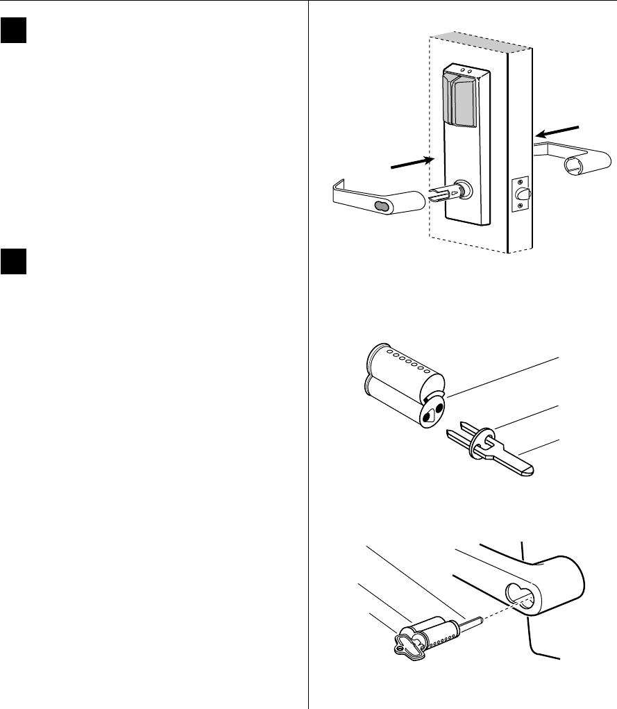
18 Install inside and outside levers
Note: To use a core and throw member from a manu-
facturer other than BEST with a Electronic Stand-alone
Lock, see the
Installation Instructions for 9K Non-inter-
changeable Cores & Throw Members
(T56093) and
skip task 19.
■With the handle pointing toward the door hinges,
position a lever on the outside sleeve and push firmly
on the lever until it is seated. Repeat, placing the other
lever on the inside sleeve.
19 Install core and throw member
1 Install the blocking plate onto the throw member.
Caution:
You must use the blocking plate to
prevent unauthorized access.
For 6-pin core users only: Install the plastic spacer
(not shown, supplied with permanent cores) instead of
the blocking plate, on the throw member.
2 Insert the control key into the core and rotate the key
15 degrees to the right.
3 Insert the throw member into the core.
4 Insert the core and throw member into the lever with
the control key.
5 Rotate the control key 15 degrees to the left and
withdraw the key.
Caution:
The control key can be used to remove
cores and to access doors. Provide adequate
security for the control key.
Figure 18 Installing the levers
Outside of door
Figure 19a Installing the blocking plate and throw
member
Core
Blocking
plate
Throw
member
Figure 19b Installing the core
Core
Control
key
Throw
member
Installation Instructions for Wi-Q™ Technology 9KQ Cylindrical Locks
12
Installing the lock
BEST ACCESS SYSTEMS
a Product Group of Stanley Security Solutions, Inc.
16 Install bottom cover
(inside escutcheon)
1 Making sure that the cover does not pinch the
wires, guide the bottom cover over the chassis onto
the fire plate.
2 Use two cover screws to secure the cover to the side of
the fire plate, as shown in Figure 16.
Note: Phillips Type 2 and T20 Torx options are available
for the cover mounting screws.
Caution:
Dress all wires away from possible pinch
points before putting the bottom cover in place.
17 Install battery holder
1 Position the battery wires against the fire plate
side wall, as shown in Figure 17.
2 Slide the battery holder behind the fire plate side tabs
until it rests on the bent battery holding tabs.
Caution:
When routing the battery wires, make
sure the wires are not routed across any sharp
edges or over any surface that could damage their
sleeving or wire insulation.
3 Connect the battery holder to the battery connector
on the wire harness.
Caution:
When connecting the battery holder,
make sure:
◆there are no loose wire connections where the
wires are inserted into the connectors.
◆the connectors are firmly mated.
Figure 16 Installing the bottom cover
Inside of door
Cover
screws
Bottom
cover
Figure 17 Installing the battery holder, eight-cell
Inside of door
Battery holder
Battery wires
Battery holding
tabs
Fire plate side
tabs
Antenna
Installation Instructions for Wi-Q™ Technology 9KQ Cylindrical Locks
13
Installation Instructions for Wi-Q™ Technology 9KQ Cylindrical Locks
Completing the installation
BEST ACCESS SYSTEMS
a Product Group of Stanley Security Solutions, Inc.
18 Install inside and outside levers
Note: To use a core and throw member from a manu-
facturer other than BEST with a Electronic Stand-alone
Lock, see the
Installation Instructions for 9K Non-inter-
changeable Cores & Throw Members
(T56093) and
skip task 19.
■With the handle pointing toward the door hinges,
position a lever on the outside sleeve and push firmly
on the lever until it is seated. Repeat, placing the other
lever on the inside sleeve.
19 Install core and throw member
1 Install the blocking plate onto the throw member.
Caution:
You must use the blocking plate to
prevent unauthorized access.
For 6-pin core users only: Install the plastic spacer
(not shown, supplied with permanent cores) instead of
the blocking plate, on the throw member.
2 Insert the control key into the core and rotate the key
15 degrees to the right.
3 Insert the throw member into the core.
4 Insert the core and throw member into the lever with
the control key.
5 Rotate the control key 15 degrees to the left and
withdraw the key.
Caution:
The control key can be used to remove
cores and to access doors. Provide adequate
security for the control key.
Figure 18 Installing the levers
Outside of door
Figure 19a Installing the blocking plate and throw
member
Core
Blocking
plate
Throw
member
Figure 19b Installing the core
Core
Control
key
Throw
member
Installation Instructions for Wi-Q™ Technology 9KQ Cylindrical Locks
14
Completing the installation
BEST ACCESS SYSTEMS
a Product Group of Stanley Security Solutions, Inc.
20 Install top cover
(inside escutcheon)
1 Connect the antenna to its mating connector.
2 Place the top cover against the door and above the fire
plate. Slide the top cover down toward the bottom
cover as shown in Figure 20b.
Caution:
As you slide the top cover onto the fire
plate, feed the antenna wire down into the
bottom cover. Be sure not to pinch the antenna
wire on the bottom cover as you slide the top
cover into place.
3 Use two cover screws to secure the cover to the side of
the fire plate, as shown in Figure 20b.
Note: Phillips Type 2 and T20 Torx options are available
for the cover mounting screws.
Figure 20a Inside view of top cover
Top cover
Antenna wire
Figure 20b Installing the top cover
Top cover
Inside of door
Cover screws
Antenna wire

Installation Instructions for Wi-Q™ Technology 9KQ Cylindrical Locks
BEST ACCESS SYSTEMS
a Product Group of Stanley Security Solutions, Inc.
15
Installation Instructions for Wi-Q™ Technology 9KQ Cylindrical Locks
Completing the installation
21 Test lock
For 9KQ Locks with keypad:
To test the lock for proper operation before the lock is pro-
grammed, follow these instructions:
1 Press
1234.
2 Press
#.
The green light flashes and the locking mechanism
unlocks.
3 Turn the lever and open the door.
For all other locks:
To test the lock for proper operation before the lock is pro-
grammed, use the temporary operator card that came
with the lock. This card is for temporary use only. After
permanent cards have been programmed for the lock, the
temporary card should be deleted.
1 Use the temporary operator card to activate the lock.
Note: If the lock has a proximity card reader, it may
have already been activated by the presence of an
object near the card reader.
2 Use the temporary operator card to access the lock.
3 The green light flashes and the locking mechanism
unlocks.
4 Turn the lever or knob and open the door.
5 With the door closed, insert and turn the key to
unlatch the door.
If the mechanism doesn’t unlock, refer to the follow-
ing table. For additional troubleshooting instructions,
see the Service Manual
.
LEDs Sounder You should
Single
red flash
— Use the card at a moderate
speed.
Red
flashes
3 short
tones
Use the temporary operator
card provided with the lock.
Green
flashes
— Check the motor connection.
— — Check the battery connection.
BEST ACCESS SYSTEMS
a Product Group of Stanley Security Solutions, Inc.
© 2008–09 Stanley Security Solutions, Inc
T82619/Rev B 3109013 ER-7991-12 Oct 2009
BEST ACCESS SYSTEMS
a Product Group of Stanley Security Solutions, Inc
1
Contents
These installation instructions describe how to install your
45HQ Mortise Lock. Topics covered include:
Preparing the door
........................................................ 1
Configuring and installing the mortise case
.............. 3
Installing the trim
.......................................................... 4
Completing the installation
.......................................... 9
Patents
Products covered by one or more of the following patents:
6,720,861
1Identify holes to drill
1 Determine the lock function to be installed.
Caution: Determine the inside and outside, hand, and
bevel of the door.
2 See the
Holes by Function
table and Figure 1 to
determine the holes to be drilled for the lock function.
Functions
Holes by Function
DV TV
Holes to drill I/S O/S I/S O/S
AForged trim
(2 holes)†
† Determine trim holes based on trim type.
Through
door
Through
door
BHarness†Through
door
Through
door
CStandard cylinder ■■
DSensor & motor wire
(2 holes) ■ ■
FThumb turn ■
GTrim mounting
(2 holes)‡
‡ Because these holes pass through the mortise pocket,
it is recommended that each hole be drilled separately
rather than straight through.
Through
door
Through
door
HLever†† Through
door
Through
door
JDoor sensing channel
(2 holes)
DO NOT
DRILL
See Figure
1
B
J
BA
A
C
F
H
DD
G
G
J
J
Figure 1 Identifying holes to drill
For hole sizes, see the
Q06 Template
(T82606).
Installation Instructions for
Wi-Q™ Technology 45HQ Mortise Locks
Installation Instructions for Wi-Q™ Technology 45HQ Mortise Locks
BEST ACCESS SYSTEMS
a Product Group of Stanley Security Solutions, Inc
Preparing the door
2
2Align templates
Note: If the door is a fabricated hollow metal door,
determine whether it is properly reinforced to support
the lock. If door reinforcement is not adequate, consult
the door manufacturer for information on proper
reinforcement. For dimensions for preparing metal
doors, see the Q03 Template—Installation
Specifications for 45HQ Mortise Locks (T82603).
1 Separate the four templates provided on the
Q06
Template—Installation Template for 45HQ Mortise
Locks
(T82606).
2 Position one of the door edge templates on the door,
making sure that the lock case mortise shown on the
template aligns with the mortise pocket prepared in
the door.
3 Using the centerlines on the door edge template as a
guide, position the appropriate door template on each
side of the door. You need to take the bevel into
account. Tape the templates to the door.
3Center punch and drill holes
1 Center punch the necessary drill points. See the
instructions on the template.
2 Drill the holes.
Note 1: To locate the center of a hole on the opposite
side of the door, drill a pilot hole completely through
the door.
Note 2: For holes through the door, it is best to drill
halfway from each side of the door to prevent the door
from splintering.
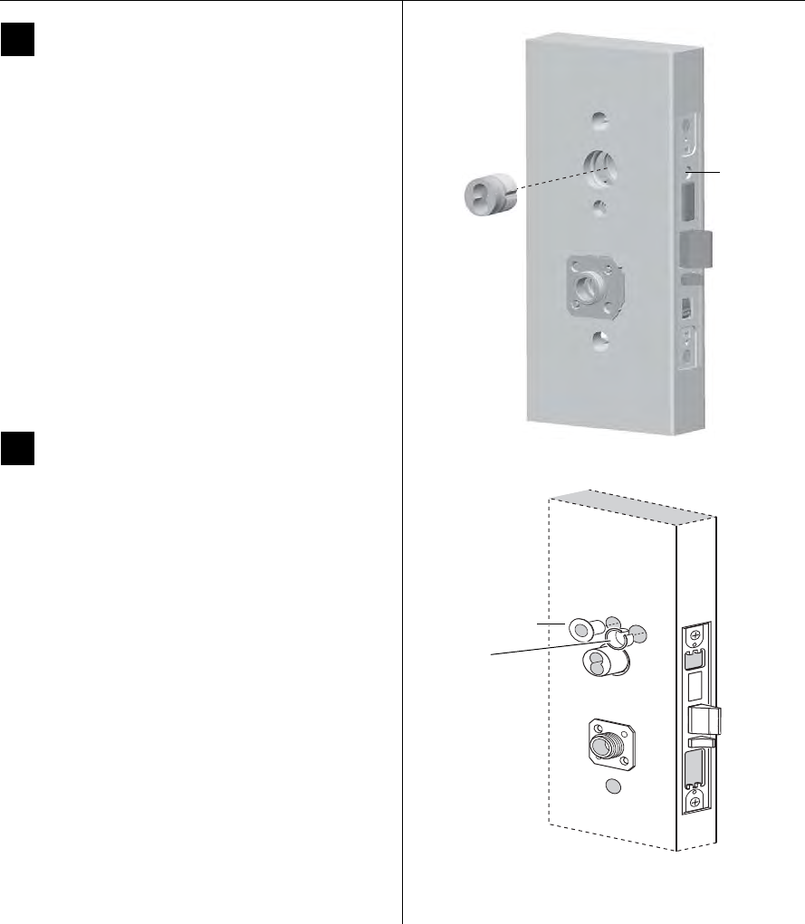
4Install door status switch
(optional for deadbolt TV function locks
only)
1 Position the shield on the door status switch with the
notch facing downwards (towards the mortise
pocket).
Caution: Make sure the wires are not routed across any
sharp edges or over any surface that could damage its
sleeving.
Figure 2 Aligning the templates
Installation
template
Door edge
template
Centerline
Centerline
Figure 3 Installing the door status switch
Door
status
switch
Shield
Installation Instructions for Wi-Q™ Technology 45HQ Mortise Locks
BEST ACCESS SYSTEMS
a Product Group of Stanley Security Solutions, Inc
3
Installation Instructions for Wi-Q™ Technology 45HQ Mortise Locks
Configuring & installing the mortise case
2 Feed the wires for the door status switch into the door
status switch hole and through the channel into the
mortise cavity and out through one of the sensor and
motor wire holes.
3 Press fit the door status switch assembly into the door
status switch hole.
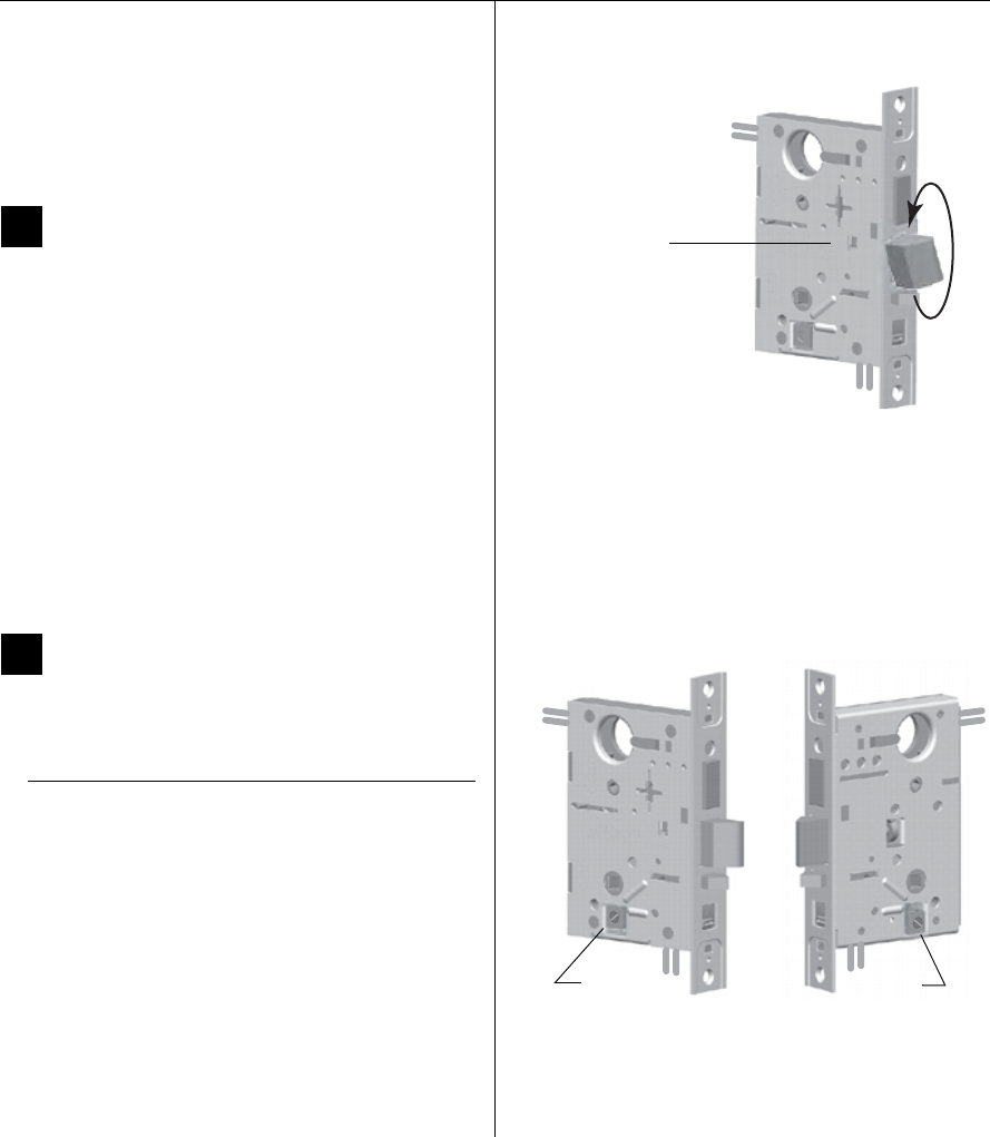
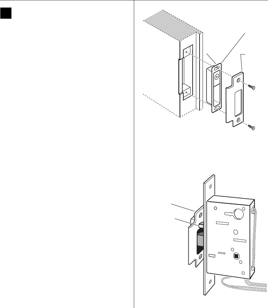
5Rotate latchbolt
(if necessary)
Note: If a function specific mortise case was ordered,
some steps for configuring the case have already been
performed at the factory.
1 Determine whether you need to rotate the latchbolt to
match the handing of the door.
Note: The angled surface of the latchbolt must contact
the strike when the door closes.
2 If you need to rotate the latchbolt, insert a flat blade
screwdriver into the latch access point approximately
1/2″ into the case and press to extend the latch out of
the case. See Figure 4.
3 Rotate the latchbolt 190 degrees (slightly past 180
degrees) and allow it to retract into the case.
6Position hub toggles
(if necessary)
1 Check whether the hub toggles are in the proper
position for the lock. See the table below and Figure 5.
Note: For LH & LHRB doors, the inside is the back side
of the case and the outside is the cover side of the
case.
For RH & RHRB doors, the inside is the cover side of the
case and the outside is the back side of the case. The
cover is mounted to the case with four screws.
2 To change the position of a hub toggle, remove the
toggle screw, move the toggle into the desired
position, and re-tighten the screw.
Hub toggle positions
Function Hub toggle positions
DV, T V Inside down (always unlocked) &
outside up (lockable)
Figure 4 Rotating the latchbolt
Latch access point
Figure 5 Positioning hub toggles
Hub toggleHub toggle
Installation Instructions for Wi-Q™ Technology 45HQ Mortise Locks
BEST ACCESS SYSTEMS
a Product Group of Stanley Security Solutions, Inc
Installing the trim
4
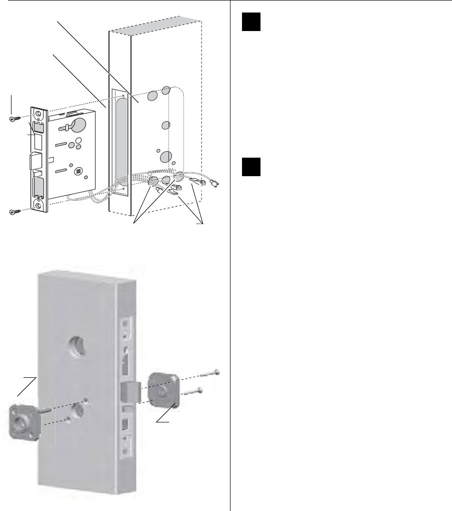
7Install mortise case
1 Drill the holes for the case mounting screws.
2 Insert the mortise case into the mortise cavity, while
feeding the sensor and motor wires into the mortise
cavity and out the two sensor & motor wire holes to
the inside of the door as shown in Figure 6.
Note: The armored front of the mortise case self-
adjusts to the door bevel.
3 Secure the mortise case with the case mounting
screws.
8Install trim mounting plates
1 Insert the outside trim mounting plate through the
door and mortise case.
2 Position the inside trim mounting plate opposite the
outside trim mounting plate and screw them securely
in place.
Caution: Do not overtighten the trim mounting plate
screws. Overtightening may damage the locking
mechanism.
3 By temporarily installing a lever, test the lock to make
sure that it doesn’t bind.
Figure 6 Installing the mortise case (inside of door)
Sensor & motor
wire holes
Mortise case
Mortise cavity
Case
mounting
screws
Sensor wires
and motor
wires
Figure 7 Installing the trim mounting plates
Outside
mounting
plate
Inside
mounting
plate
Installation Instructions for Wi-Q™ Technology 45HQ Mortise Locks
BEST ACCESS SYSTEMS
a Product Group of Stanley Security Solutions, Inc
5
Installation Instructions for Wi-Q™ Technology 45HQ Mortise Locks
Installing the trim
9 Install concealed cylinder & core
1 Use a cylinder wrench to thread the cylinder into the
mortise case so that the groove around the cylinder is
even with the door surface as shown in Figure 8.
Caution: A malfunction can occur if the cylinder is
threaded in too far.
2 Secure the cylinder in the mortise case with the
cylinder retainer screw.
3 Insert the control key into the core and rotate the key
15 degrees to the right.
4 With the control key in the core, insert the core into
the cylinder.
5 Rotate the control key 15 degrees to the left and
withdraw the key.
Caution: The control key can be used to remove cores
and to access doors. Provide adequate security for the
control key.
10 Install trim hole insert and bushing
1 Insert the trim hole insert into the upper trim hole on
the outside of the door, as shown in Figure 9.
2 Insert the bushing into the harness hole on the outside
of the door, as shown in Figure 9.
Figure 8 Installing the concealed cylinder
Cylinder
retainer
screw
Figure 9 Installing the trim hole insert and bushing
Trim hole insert
Bushing
Outside of door
Installation Instructions for Wi-Q™ Technology 45HQ Mortise Locks
BEST ACCESS SYSTEMS
a Product Group of Stanley Security Solutions, Inc
Installing the trim
6
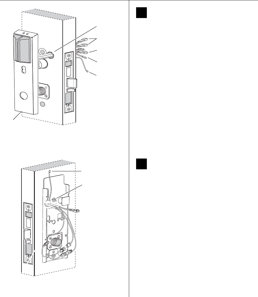
11 Route wire harnesses and position
outside escutcheon
1 From the outside of the door, feed the motor
connector, battery connector, and sensor connectors
through the harness hole.
Caution: When routing the connectors, make sure the
harnesses are not routed across any sharp edges or over
any surface that could damage their sleeving or wire
insulation.
2 Perform these steps:
a Firmly press the outside escutcheon in position on
the door. The core should be flush with the outer
surface of the escutcheon.
b If necessary, adjust the cylinder depth plus or
minus one turn so that the core is flush with the
outer surface of the escutcheon.
c Secure the cylinder in the mortise case with the
cylinder clamp screw.
3 Rest the outside escutcheon on the door by inserting
the trim studs into the trim holes.
12 Install fire plate
1 From the inside of the door, feed the wiring through
the fire plate harness hole.
2 Position the fire plate on the door so that the inside
mounting plate fits through the square opening in the
fire plate.
3 Insert the two counter sunk mounting screws into the
holes at the top and bottom of the fire plate.
4 Tighten the mounting screws until the fire plate is
securely mounted to the door.
Figure 10 Feeding the wire harness connectors through
the harness hole
Motor
connector
Outside
escutcheon
Outside of door
Sensor
connectors
Battery
connector
Harness
hole
Antenna
Figure 11 Installing the fire plate
Inside of door
Mounting
screws
Antenna
wire
Installation Instructions for Wi-Q™ Technology 45HQ Mortise Locks
BEST ACCESS SYSTEMS
a Product Group of Stanley Security Solutions, Inc
7
Installation Instructions for Wi-Q™ Technology 45HQ Mortise Locks
Installing the trim
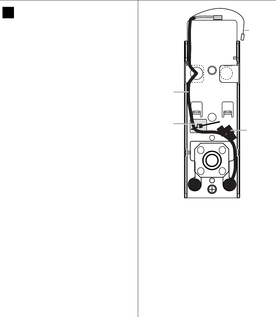
13 Connect wire harnesses
1 From the inside of the door, make the following
connections:
2 Insert the plastic wire tie through the mounting clip
and secure the wires as shown in Figure 12.
Note: It is physically possible to connect the key
override sensor connector from the mortise case to the
battery connector from the wire harness. To avoid this
mistake, connect only the connectors with matching
wire colors.
Caution: When making the motor connection and
sensor connections, make sure:
◆there are no loose wire connections where the
wires are inserted into the connectors
◆the connectors are firmly mated
Wire connection Colors No. of
wires
No. of
pins
Motor Yellow-gray 2 2
Key override sensor Gray 23
Deadbolt sensor Blue 23
RQE Orange-brown 2 3
Door sensing White 22
Latchbolt sensing Purple 22
Figure 12 Routing the wires
Route wire
harness on
the left side
of the fire
plate.
Mounting
clip and
wire tie
Dress wires so
that wire
connectors are
mated here.
Use electric
tape to affix
them as
needed.
Antenna wire
Installation Instructions for Wi-Q™ Technology 45HQ Mortise Locks
BEST ACCESS SYSTEMS
a Product Group of Stanley Security Solutions, Inc
Installing the trim
8
14 Install bottom cover
(inside escutcheon)
1 Position the battery wires above the side tabs and
against the side of the fire plate, as shown in
Figure 13.
2Optional for Thumb Turn option only: Make sure
that the Thumb Turn is in the upright position, as
shown in Figure 13.
3Making sure that the cover does not pinch the
wires, guide the bottom cover over the chassis onto
the fire plate.
Note: Phillips Type 2 and T20 Torx options are available
for the cover mounting screws.
Figure 13 Installing the bottom cover
Inside of door
Bottom
cover
Cover
screws
Battery wires
Thumb turn
(optional)
Antenna wire
Installation Instructions for Wi-Q™ Technology 45HQ Mortise Locks
BEST ACCESS SYSTEMS
a Product Group of Stanley Security Solutions, Inc
9
Installation Instructions for Wi-Q™ Technology 45HQ Mortise Locks
Completing the installation
15 Install battery holder
1 Position the battery wires against the fire plate
side wall, as shown in Figure 14.
2 Slide the battery holder behind the fire plate side tabs
until it rests on the bent battery holding tabs.
Caution: When routing the battery wires, make sure the
wires are not routed across any sharp edges or over any
surface that could damage their sleeving or wire
insulation.
3 Connect the battery pack to the battery connector on
the wire harness.
Caution: When connecting the battery pack, make sure:
◆there are no loose wire connections where the
wires are inserted into the connectors.
◆the connectors are firmly mated.
16 Install inside and outside levers
1 Unscrew the inside spindle one full turn to allow the
spindles to turn freely.
2 With the handle pointing toward the door hinges,
insert the outside lever and spindles assembly into the
lock from the outside of the door.
3 Slide the inside lever onto the inside spindle and
secure it with the set screw.
4 Making sure that the core is positioned properly in the
outside escutcheon (DV and TV function Locks only)
and the escutcheons are aligned properly on the door,
tighten the escutcheon mounting screws.
Note: If a core is not available, you can use the cylinder
wrench to help you align the core opening in the
escutcheon.
5 Turn the levers to check that they operate smoothly.
Figure 14 Installing the battery holder
Inside of door
Battery holder
Battery wires
Battery wires
Battery holding
tabs
Antenna
wire
Figure 15 Installing the levers
Spindles
Location
of set
screw
Outside of door Inside of door
Spindles
Outside of door
Installation Instructions for Wi-Q™ Technology 45HQ Mortise Locks
BEST ACCESS SYSTEMS
a Product Group of Stanley Security Solutions, Inc
Completing the installation
10
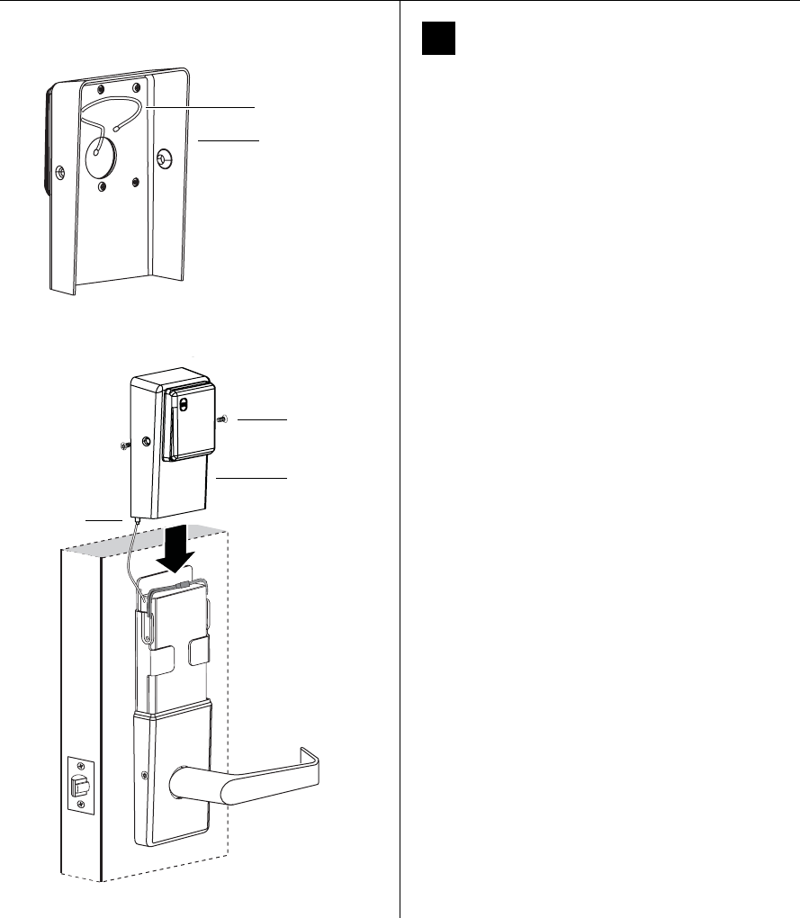
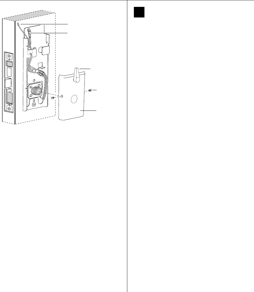
17 Install top cover
(inside escutcheon)
1 Connect the antenna to its mating connector.
2 Place the top cover against the door and above the fire
plate. Slide the top cover down toward the bottom
cover as shown in Figure 17.
Caution: As you slide the top cover onto the fire plate,
feed the antenna wire down into the bottom cover. Be
sure not to pinch the antenna wire on the bottom cover
as you slide the top cover into place.
3 Use two cover screws to secure the cover to the side of
the fire plate, as shown in Figure 17.
Note: Phillips Type 2 and T20 Torx options are available
for the cover mounting screws.
18 Install mortise case faceplate
1 Secure the mortise case faceplate to the mortise case
with the faceplate mounting screws.
2 Check the lock for proper operation.
Figure 16 Inside view of top cover
Top cover
Antenna wire
Figure 17 Installing the top cover
Inside of door
Wireless cover
Cover screws
Antenna wire
Figure 18 Installing the mortise case faceplate
Outside of door
Mortise
case
faceplate
Faceplate
mounting
screws
Installation Instructions for Wi-Q™ Technology 45HQ Mortise Locks
BEST ACCESS SYSTEMS
a Product Group of Stanley Security Solutions, Inc
11
Installation Instructions for Wi-Q™ Technology 45HQ Mortise Locks
Completing the installation
19 Install strike box and strike plate
1 Insert the strike box into the mortise in the door jamb.
Place the strike plate over the strike box and secure the
strike with the screws provided.
2 Check the position of the auxiliary bolt against the
strike plate.
Caution: The auxiliary bolt must make contact with the
strike plate. The auxiliary bolt deadlocks the latchbolt
and prevents someone from forcing the latch open
when the door is closed. If the incorrect strike is
installed, a lock-in can occur.
Note: The recommended gap between the door and
jamb is 1/8″.
Figure 19a Installing the strike box and strike plate
Strike
box with
magnet
Strike
plate
Door jamb
Make sure to
position the
magnet at
the top.
Figure 19b Positioning the strike
Auxiliary bolt
Strike plate

Installation Instructions for Wi-Q™ Technology 45HQ Mortise Locks
BEST ACCESS SYSTEMS
a Product Group of Stanley Security Solutions, Inc
12
Testing the lock
20 Test lock
For 45HQ Locks with keypad
To test the lock for proper operation before the lock is
programmed, follow these instructions:
1 Press
1234.
2 Press #.
The green light flashes and the locking mechanism
unlocks.
3 Turn the lever and open the door.
For all other locks:
To test the lock for proper operation before the lock is
programmed, use the temporary operator card that came
with the lock. This card is for temporary use only. After
permanent cards have been programmed for the lock, the
temporary card should be deleted.
1 Use the temporary operator card to activate the lock.
Note: If the lock has a proximity card reader, it may
have already been activated by the presence of an
object near the card reader.
2 Use the temporary operator card to access the lock.
The green light flashes and the locking mechanism
unlocks.
3 Turn the lever and open the door.
If the mechanism doesn’t unlock, refer to the following
table. For additional troubleshooting instructions, see the
Service Manual
.
For all locks
1 Insert and turn the key to unlatch the door.
For all TV function locks
2 From the inside of the door, turn the turn knob and
make sure that the deadbolt operates properly.
LEDs Sounder You should
Single
red flash
— Use the card at a moderate speed.
Red
flashes
3 short
tones
Use the temporary operator card
provided with the lock.
Green
flashes
— Check the motor connection.
— — Check the battery connection.
©2008–2009 Stanley Security Solutions, Inc
T82623/Rev C 3108931 ER-7991-12 Oct 2009
BEST ACCESS SYSTEMS
a Product Group of Stanley Security Solutions, Inc.
1
Introduction
These installation instructions describe how to install your
BEST® Wi-Q Technology™ EXQ Series Exit Hardware Trim.
Electronic Stand-Alone Exit Hardware Trim is available for
use with the following types of wide stile exit devices:
Precision® brand manufactured by Stanley (2000 Series),
Von Duprin® (98/99 Series), and Sargent® (8800 Series).
Not all features are available for all exit device configura-
tions. The table below details what sensors are available
for which exit device configurations:
n
Device DSa
a. Door position sensing
TSb
b. Request-to-exit (PHI touchbar monitoring)
LSc
c. Latch sensing
Precision
Rim (2100) ■■■
Surface Vertical (2200) ■■■
Mortise (2300) ■
Wood Door Concealed (2700) ■■■
Concealed Vertical (2800) ■■■
Von Duprind
d. Von Duprin is a registered trademark of Von Duprin, Inc.
Rim ■ ■
Surface Vertical ■
Concealed Vertical ■
Sargente
e. Sargent is a registered trademark of Sargent Mfg. Co.
Rimf
f. Latch must have lift-type trim input (8863)
■
Contents
These instructions cover the following topics:
Planning the installation................................................ 1
Preparing the door.......................................................... 3
Installing the exit hardware and trim ........................... 7
Completing the installation ......................................... 16
Site survey
Use the following survey to record information about the
installation site and hardware application.
Exit hardware type:
Door handing and bevel:
❑Left-hand reverse bevel (LHRB)
❑Right-hand reverse bevel (RHRB)
Door type:
Door thickness: inches (1-3/4″ to 2-1/4″)
Components checklist
Use the following checklist to make sure that you have the
items necessary to install your EXQ Exit Hardware Trim.
❑rim ❑surface vertical rod
❑mortise ❑concealed vertical rod
❑Wood ❑Metal
❑Escutcheon and
lever assembly
Installation Instructions for
Wi-Q Technology™ EXQ
Exit Hardware Trim
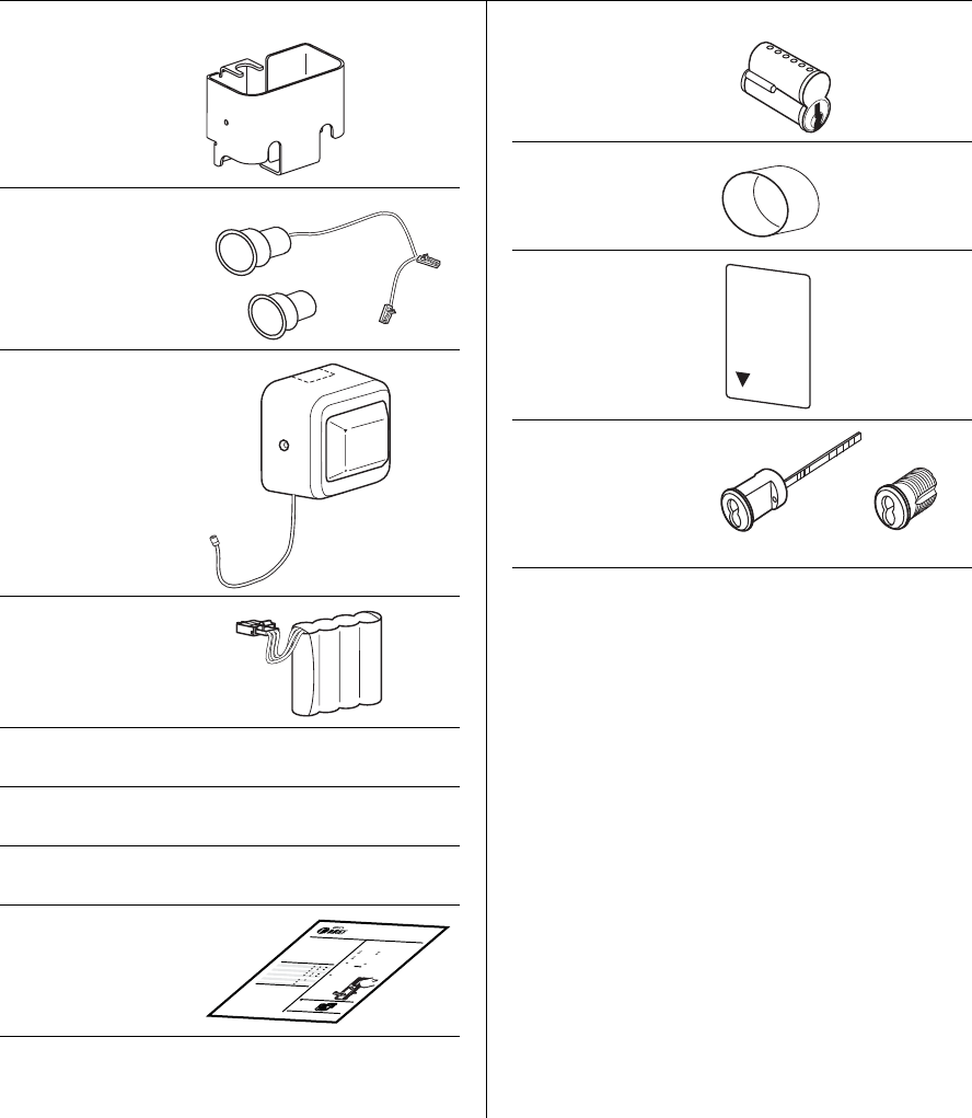
Installation Instructions for Wi-Q Technology™ EXQ Exit Hardware Trim
2BEST ACCESS SYSTEMS
a Product Group of Stanley Security Solutions, Inc.
❑Battery bracket
❑Door position
switch with
magnet
❑Battery cover with
antenna
❑Battery pack
❑Battery cover screw
package
❑Bar code ID sticker
(for your records)
❑Cable ties, butt-
splices, and tape
❑Installation
templates and
instructions
BEST ACCESS SYSTEMS
a Product Group of Stanley Security Solutions, Inc.
1
Introduction
These installation instructions describe how to install your
BEST® Wi-Q Technology™ EXQ Series Exit Hardware Trim.
Electronic Stand-Alone Exit Hardware Trim is available for
use with the following types of wide stile exit devices
manufactured by Stanley-Precision Hardware (2000
Series) and VonDuprin® (98/99 Serie s):
Not all features are available for all exit device configura-
tions. The table below details what sensors are available
for which exit device configurations:
n
Contents
These instructions cover the following topics:
Planning the installation................................................1
Preparing the door.......................................................... 4
Installing the exit hardware and trim............................8
Completing the installation..........................................15
Device DS
a
a. Door position sensing
TS
b
b. Request-to-exit (PHI touchbar monitoring)
LS
c
c. Latch sensing
Precision
Rim (2100)
Surface Vertical (2200)
Mortise (2300)
Wood Door Concealed (2700)
Concealed Vertical (2800)
Von Duprin
Rim
Surface Vertical
Concealed Vertical
Site survey
Use the following survey to record information about the
installation site and hardware application.
Exit hardware type:
Door handing and bevel:
Left-hand reverse bevel (LHRB)
Right-hand reverse bevel (RHRB)
Door type:
Door thickness: inches (1-3/4″ to 2-1/4″)
Components checklist
Use the following checklist to make sure that you have the
items necessary to install your EXQ Exit Hardware Trim.
rim surface vertical rod
mortise concealed vertical rod
Wood Metal
Escutcheon and
lever assembly
Battery bracket
Installation Instructions for
Wi-Q Technology™ EXQ
Exit Hardware Trim
Tools required
Use the following checklist to make sure that you have the
tools necessary to install your EXQ Exit Hardware Trim.
For Precision® Hardware and Sargent installations
❑1-3/8” dia hole saw (EV function only)
❑1-1/8” dia hole saw
For Von Duprin® installations
❑2” dia hole saw
❑3/4” dia hole saw
For BEST® cylinders
❑BEST ED211 cylinder wrench
For surface vertical exit devices
❑Razor blade
❑7-pin core (only
included if ordered
with trim)
❑Cylinder mounting
sleeve (for Von
Duprin functions
only)
❑Temporary
operator card
❑Key cylinder and
keys (only included
if ordered with
trim).
❑Electric drill (preferably corded) ❑Straight edge
❑Jigsaw ❑Square
❑Wire snips ❑Pencil/marker
❑Wire strippers ❑7/16” dia drill bit
❑Phillips screwdriver ❑7/8” dia drill bit
❑Measuring tape ❑1” dia hole saw
BEST
Temporary
Operator
Rim cylinder Mortise cylinder
OR
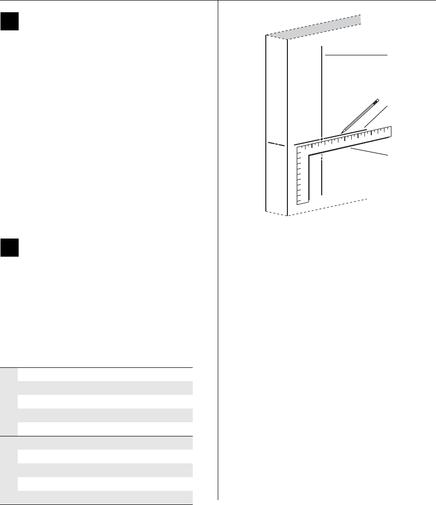
Installation Instructions for Wi-Q Technology™ EXQ Exit Hardware Trim
BEST ACCESS SYSTEMS
a Product Group of Stanley Security Solutions, Inc.
3
Installation Instructions for Wi-Q Technology™ EXQ Exit Hardware Trim
Preparing the door
1Mark centerlines
Note 1: If retrofitting to an existing exit hardware instal-
lation, skip this task. Instead, remove the exit hardware
from the door.
Note 2: If the door is a fabricated hollow metal door,
determine whether it is properly reinforced to support the
lock. If door reinforcement is not adequate, consult the
door manufacturer for information on proper reinforce-
ment.
1 Prepare the push side of the door according to the exit
device manufacturer’s installation instructions.
Note: The tape-on template supplied with the EXQ trim
will supersede the exit device template in the trim area.
2 Transfer horizontal and vertical centerlines to the out-
side of the door face.
Note: When measuring from the edge of the door, take
into account the door bevel (if any).
2Determine required door prep
1 Determine which template is applicable (Q08 for Preci-
sion and Sargent, Q07 for Von Duprin) and discard the
other one.
2 Based on the kind of exit device you have, use the table
below to locate the appropriate door preparation.
3 On the template, circle the holes needed for your instal-
lation and cross out those that are not applicable.
n
Device Figure
Precision
Rim (2100) Figure 2
Surface Vertical (2200) Figure 3
Mortise (2300) Figure 4
Wood Door Concealed (2700) Figure 3
Concealed Vertical (2800) Figure 3
Von Duprin
Rim (with RQE) Figure 5
Rim (without RQE) Figure 7
Surface Vertical Figure 7
Concealed Vertical Figure 7
Sargent Rim Figure 6
Figure 1 Marking centerlines on outside door face
Vertical
centerline
Horizontal
centerline
Straight
edge
Note: Follow the Precision 2300
door preparation for Sargent,
ignoring any steps directly per-
taining to the mortise lock or
key cylinder.
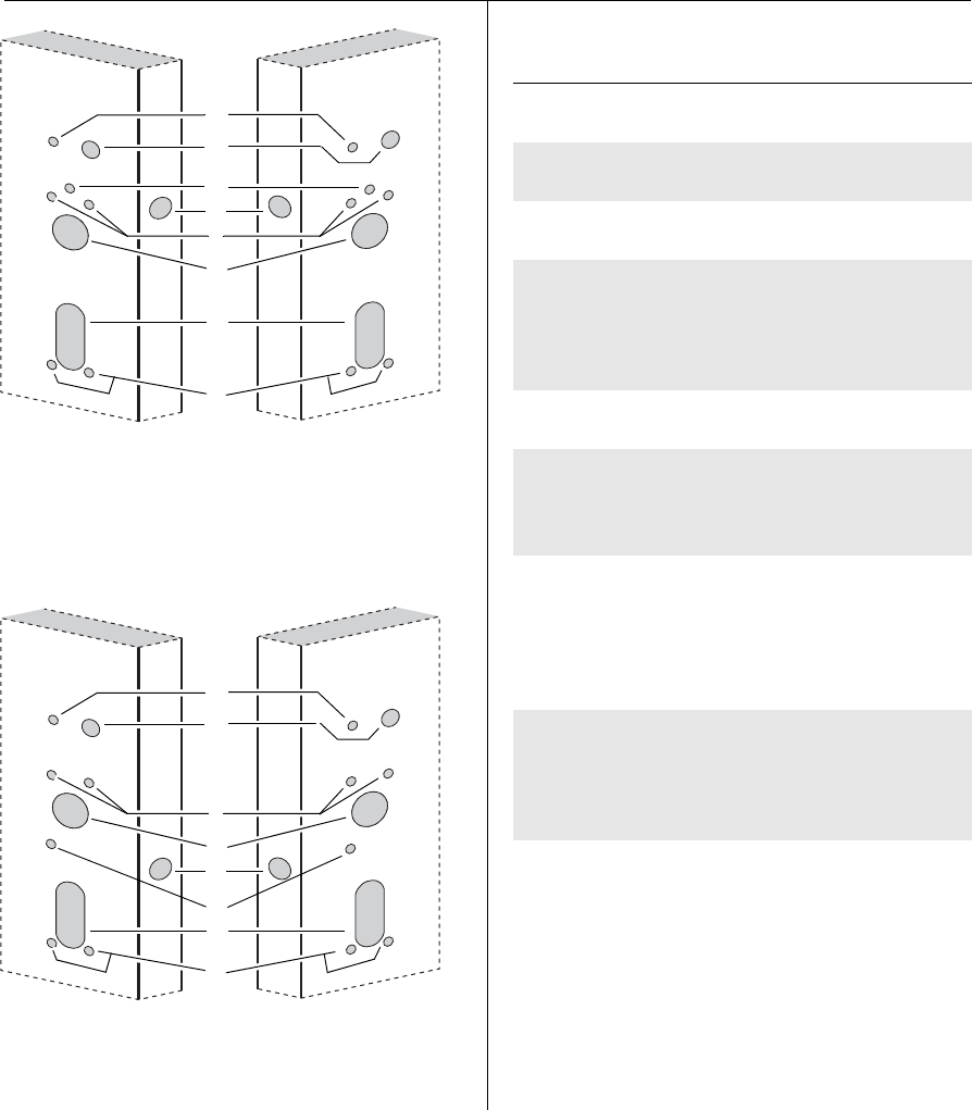
Installation Instructions for Wi-Q Technology™ EXQ Exit Hardware Trim
BEST ACCESS SYSTEMS
a Product Group of Stanley Security Solutions, Inc.
4
Preparing the door
Hole Description Instructions
ABattery bracket hole 7/16″ diameter, thru
door
BBattery bracket/har-
ness hole
7/8″ diameter, thru door
CSensor harness rout-
ing hole
7/16″ diameter, thru
door
DDoor sensing switch
mounting hole and
channel
1” diameter hole,
drilled 1-3/4” deep, then
7/16” channel to intersect
door sensing wire routing
hole.
EEscutcheon mount-
ing holes
7/16″ diameter, thru
door
FDoor sensing switch
magnet hole (in door
frame or opposing
door leaf)
1” diameter hole,
drilled 1-3/4” deep
(NOT SHOWN).
GCylinder hole Precision: 1-3/8″ dia-
meter, thru door (for
2300, only into mortise
cavity)
Von Duprin: 2″diameter
thru door
HLift finger slot Precision/Sargent:
1-1/8″diameter slot, thru
door
Von Duprin: 3/4″diame-
ter slot, thru door
Figure 2 Outside door prep for use with
Precision exit hardware, 2100 Series
Outside of RHRB doorOutside of LHRB door
A
B
D
E
C
G
H
E
Figure 3 Outside door prep for use with
Precision exit hardware, 2200, 2700,
and 2800 Series
Outside of RHRB door
Outside of LHRB door
A
B
D
E
C
G
H
E
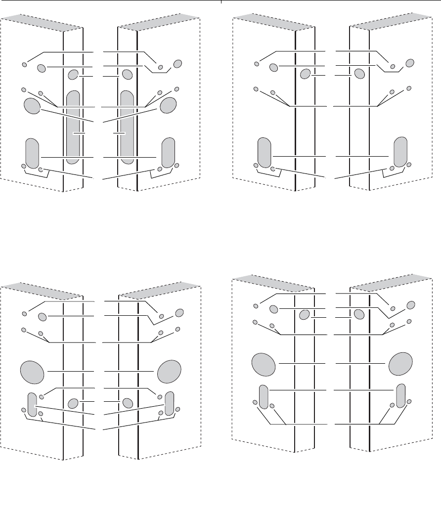
Installation Instructions for Wi-Q Technology™ EXQ Exit Hardware Trim
5
Installation Instructions for Wi-Q Technology™ EXQ Exit Hardware Trim
Preparing the door
BEST ACCESS SYSTEMS
a Product Group of Stanley Security Solutions, Inc.
Figure 4 Outside door prep for use with
Precision exit hardware, 2300 Series
Outside of RHRB doorOutside of LHRB door
A
B
D
E
G
H
E
mortise
cavity
Figure 5 Outside door prep for use with
Von Duprin exit hardware, Rim with RQE only
Outside of RHRB door
Outside of LHRB door
E
G
C
D
E
H
A
B
Figure 6 Outside door prep for use with
Sargent 8863 exit hardware
Outside of RHRB doorOutside of LHRB door
A
B
D
E
H
E
Figure 7 Outside door prep for use with
Von Duprin exit hardware. Use for all Von
Duprin vertical rods and rim without RQE
Outside of RHRB doorOutside of LHRB door
E
G
D
E
H
A
B
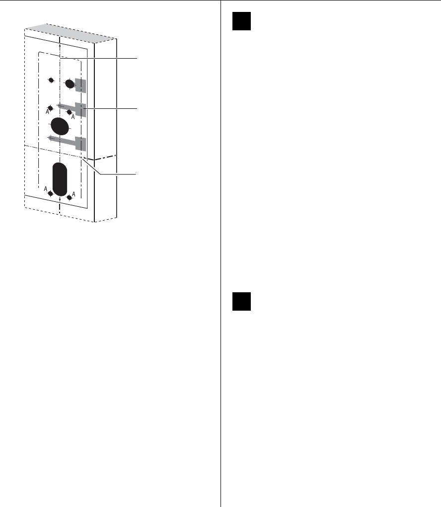
Installation Instructions for Wi-Q Technology™ EXQ Exit Hardware Trim
BEST ACCESS SYSTEMS
a Product Group of Stanley Security Solutions, Inc.
6
Preparing the door
3Position trim template and mark drill
points
1 For new installations
a Cut the applicable template along the dashed lines.
b Align the horizontal and vertical centerlines
marked on the template with the centerlines
marked on the OUTSIDE of the door (from step 1).
See Figure 8.
For retrofit installations
Align the mounting holes for the escutcheon and
lock stile case shown on the template with the
mounting holes already present in the door.
Note: The outside escutcheon is mounted using the
four lock stile case mounting holes (‘A’ holes); these
holes must be 7/16″ in diameter and drilled com-
pletely through the door.
2 Tape the template to the OUTSIDE of the door in the
properly aligned position.
3 Center punch the necessary drill points. Refer to the
instructions on the template and the figures of the
previous step.
4Mortise for mortise case and faceplate
(mortise exit devices only)
Note: If retrofitting the EXQ Exit Hardware Trim to an
existing exit hardware installation, skip this task.
Mortise the edge of the door for the mortise case and
faceplate; follow the instructions provided by the exit
hardware manufacturer.
Figure 8 Positioning the trim template,
Q08 LHRB shown
Trim template
Horizontal centerline
of lock
Vertical centerline
of lock
Outside of door
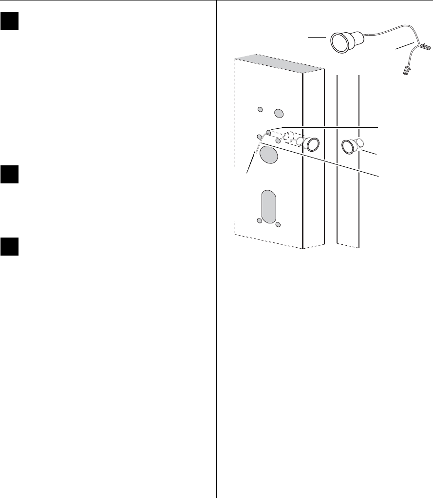
Installation Instructions for Wi-Q Technology™ EXQ Exit Hardware Trim
BEST ACCESS SYSTEMS
a Product Group of Stanley Security Solutions, Inc.
7
Installation Instructions for Wi-Q Technology™ EXQ Exit Hardware Trim
Installing the exit hardware and trim
5Drill holes
Caution: Double-check for the correct lock func-
tion, hand, and bevel before drilling.
1 Drill the trim holes that are required for your applica-
tion; follow the instructions on the trim template and
refer to the figures in step 2.
Note 1: To locate the center of a hole on the opposite
side of the door, drill a small pilot hole through the door.
Note 2: For holes through a wood door, drill halfway
from each side of the door to keep the door from splinter-
ing.
6Install mortise case
(mortise exit devices only)
Install the mortise case in the door; follow the instruc-
tions provided by the exit hardware manufacturer.
7Install door sensing switch
1 Clip off the purple wires and connector and remove.
2 Clip off the connector from the white door sensing
harness (with black sleeving) and leave as much wire
as possible. See Figure 9. These wires will be butt-
spliced to the sensing harness from the trim. See
“Route sensor wires” on page 14.
3 Route the door sensing switch wires through the chan-
nel and out through the wire routing hole to the exit
device side. See Figure 9.
4 Press-fit the door sensing switch into the 1” diameter
hole in the door.
5 Mark and drill 1” diameter hole in the frame, aligned
with the door position switch (for the magnet).
Note: For double-door applications, this hole will be into
the edge of the opposing door leaf (not the frame).
6 Press-fit the door sensing magnet into the 1” diameter
hole in the frame.
Figure 9 Installing the door sensing switch and magnet,
Precision 2100 shown
Door sensing
magnet
Door sensing
harness
Wire routing
hole
Inside Door Frame
See Q07 and
Q08 templates
for other door
sensing wire
routing.
Door sensing
switch Clip both
connectors
off here
Route
the door
sensing
harness
to the
inside.
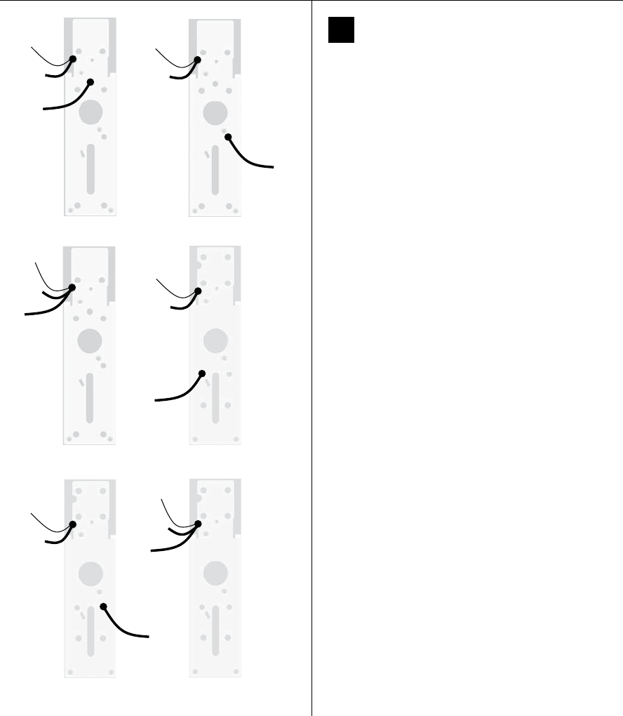
Installation Instructions for Wi-Q Technology™ EXQ Exit Hardware Trim
BEST ACCESS SYSTEMS
a Product Group of Stanley Security Solutions, Inc.
8
Installing the exit hardware and trim
8Re-route sensor harness (if applicable)
Looking at the back of the trim, compare it to the pictures
in Figure 10. If your trim does not match the proper pic-
ture, then follow the applicable steps below to re-route
the sensor harness.
Figure 10 Variations of EXQ Trim rear view
PHI Rim
(2100) PHI Vertical
(2200/2700/2800)
PHI Mortise (2300)
& Sargent (8800)
Von Duprin
Rim (LHRB)
Von Duprin
Rim (RHRB)
Von Duprin
Verticals
Antenna
cable
Primary
harness
Sensor
harness
Antenna
cable
Primary
harness
Sensor
harness
Antenna
cable
Primary
harness
Sensor
harness
Antenna
cable
Primary
harness
Sensor
harness
Antenna
cable
Primary
harness
Sensor
harness
Antenna
cable
Primary
harness
Sensor
harness
Installation Instructions for Wi-Q Technology™ EXQ Exit Hardware Trim
BEST ACCESS SYSTEMS
a Product Group of Stanley Security Solutions, Inc.
9
Installation Instructions for Wi-Q Technology™ EXQ Exit Hardware Trim
Installing the exit hardware and trim
1 Carefully peel the black gasket off of the back of the
trim. Set it aside to be re-applied later.
2 Remove the backplate from the trim by removing the
four screws that attach it.
3 While the gasket and backplate are removed, change
the handing of the trim if necessary.
Do so by removing the four threaded guide pins and
retaining ring as shown in Figure 11, pulling out and
flipping the lever 180 degrees, and then reassembling.
For Precision 2100 devices
4 Re-route the sensor harness out through the alternate
wire-routing hole as shown in Figure 12.
5 Reattach the backplate ensuring that the springs are
properly seated and wires are not pinched.
6 Reapply the gasket.
Figure 11 Changing the hand of the trim (if needed)
Retaining
ring
Guide pins
Lever
Yoke finger
Figure 12 Re-routing the sensor harness for Precision
2100 exit devices
Route
sensor
harness
here
Backplate
Sensor
harness

Installation Instructions for Wi-Q Technology™ EXQ Exit Hardware Trim
BEST ACCESS SYSTEMS
a Product Group of Stanley Security Solutions, Inc.
9
Installation Instructions for Wi-Q Technology™ EXQ Exit Hardware Trim
Installing the exit hardware and trim
1 Carefully peel the black gasket off of the back of the
trim. Set it aside to be re-applied later.
2 Remove the backplate from the trim by removing the
four screws that attach it.
3 While the gasket and backplate are removed, change
the handing of the trim if necessary.
Do so by removing the four threaded guide pins and
retaining ring as shown in Figure 11, pulling out and
flipping the lever 180 degrees, and then reassembling.
For Precision 2100 devices
4 Re-route the sensor harness out through the alternate
wire-routing hole as shown in Figure 12.
5 Reattach the backplate ensuring that the springs are
properly seated and wires are not pinched.
6 Reapply the gasket.
Figure 11 Changing the hand of the trim (if needed)
Retaining
ring
Guide pins
Lever
Yoke finger
Figure 12 Re-routing the sensor harness for Precision
2100 exit devices
Route
sensor
harness
here
Backplate
Sensor
harness
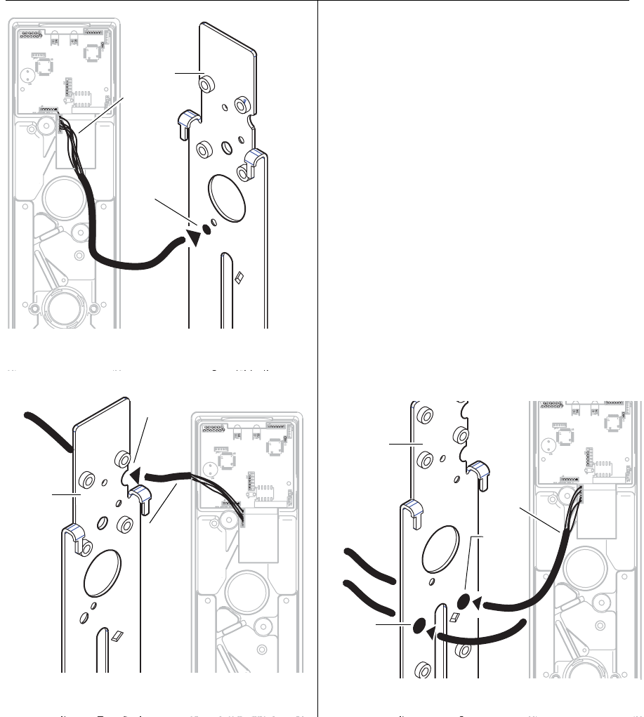
Installation Instructions for Wi-Q Technology™ EXQ Exit Hardware Trim
BEST ACCESS SYSTEMS
a Product Group of Stanley Security Solutions, Inc.
10
Installing the exit hardware and trim
For Precision 2200, 2700 and 2800 devices
4 Re-route the sensor harness around the cylinder hole
and around the escutcheon boss, then out through the
alternate wire-routing hole as shown in Figure 13.
5 Reattach the backplate ensuring that the springs are
properly seated and wires are not pinched.
6 Reapply the gasket.
For Precision 2300 and Sargent 8800 devices
4 Re-route the sensor harness toward the top of the
escutcheon to the same area as the battery cable,
antenna cable and relay shunts. See Figure 14.
5 Reattach the backplate ensuring that the springs are
properly seated and wires are not pinched.
6 Reapply the gasket.
For Von Duprin Rim devices with RQE
4 Re-route the sensor harness around the cylinder hole
and around the escutcheon boss, then out through
one of the alternate wire-routing holes (based on
handing) as shown in Figure 15.
5 Reattach the backplate ensuring that the springs are
properly seated and wires are not pinched.
6 Reapply the gasket.
Figure 13 Re-routing the sensor harness for Precision
2200, 2700 and 2800 exit devices
Route
sensor
harness
here
Backplate
Sensor
harness
Route
sensor
harness
here
Backplate
Sensor
harness
Figure 14 Re-routing the sensor harness for Precision 2300
and Sargent 8800 exit devices
Route
sensor
harness
here for
LHRB
Backplate
Sensor
harness
Figure 15 Re-routing the sensor harness for Von Duprin
with RQE
Route
sensor
harness
here for
RHRB
Installation Instructions for Wi-Q Technology™ EXQ Exit Hardware Trim
BEST ACCESS SYSTEMS
a Product Group of Stanley Security Solutions, Inc.
11
Installation Instructions for Wi-Q Technology™ EXQ Exit Hardware Trim
Installing the exit hardware and trim
For Von Duprin vertical rod devices and rim without
RQE
4 Re-route the sensor harness as shown in Figure 16.
5 Reattach the backplate ensuring that the springs are
properly seated and wires are not pinched.
6 Reapply the gasket.
9Install cylinder (Von Duprin only)
1 To determine the correct spindle length, try the cylin-
der in the door while holding the escutcheon and lock
stile case in place.
Then break off the spindle at the groove where it will
engage correctly with the latching mechanism.
If necessary break off the mounting screws as shown in
Figure 17.
2 From the front of the escutcheon, insert the cylinder
into the cylinder opening.
3 Holding the cylinder in position in the escutcheon,
insert the cylinder mounting sleeve through the back
of the escutcheon, over the cylinder.
4 Orient the cylinder and clamp plate as shown in
Figure 17. From the back of the escutcheon, secure the
cylinder and mounting sleeve using the clamp plate
and mounting screws.
Figure 16 Re-routing the sensor harness for Von Duprin
vertical rod and rim without RQE exit devices
Route
sensor
harness
here
Sensor
harness
Backplate
Figure 17 Installing the cylinder for Von Duprin
rim and rod exit devices
Rim
cylinder
Screws
Spindle Clamp
plate
Break off the
screws here.
Orient the
curve toward
the cylinder.
Mounting
sleeve
Escutcheon
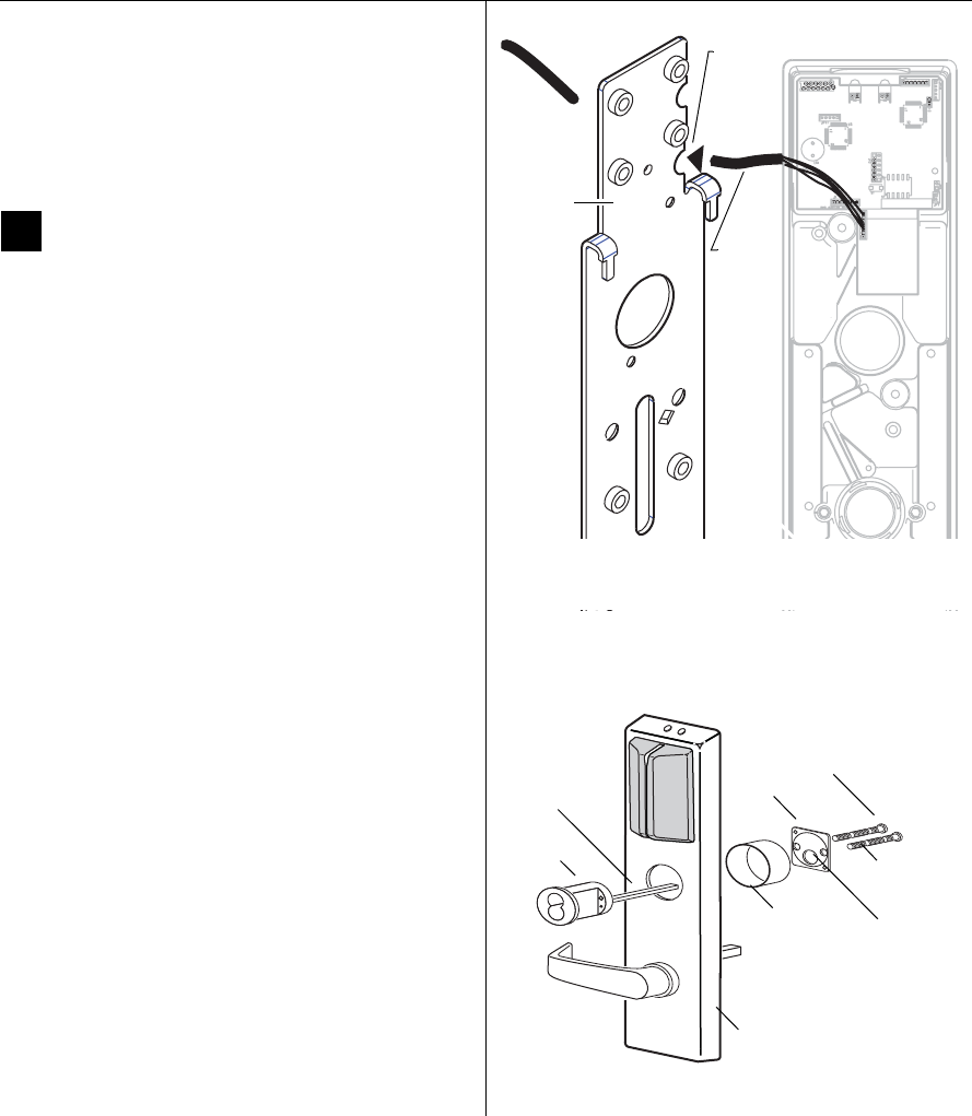
Installation Instructions for Wi-Q Technology™ EXQ Exit Hardware Trim
BEST ACCESS SYSTEMS
a Product Group of Stanley Security Solutions, Inc.
11
Installation Instructions for Wi-Q Technology™ EXQ Exit Hardware Trim
Installing the exit hardware and trim
For Von Duprin vertical rod devices and rim without
RQE
4 Re-route the sensor harness as shown in Figure 16.
5 Reattach the backplate ensuring that the springs are
properly seated and wires are not pinched.
6 Reapply the gasket.
9Install cylinder (Von Duprin only)
1 To determine the correct spindle length, try the cylin-
der in the door while holding the escutcheon and lock
stile case in place.
Then break off the spindle at the groove where it will
engage correctly with the latching mechanism.
If necessary break off the mounting screws as shown in
Figure 17.
2 From the front of the escutcheon, insert the cylinder
into the cylinder opening.
3 Holding the cylinder in position in the escutcheon,
insert the cylinder mounting sleeve through the back
of the escutcheon, over the cylinder.
4 Orient the cylinder and clamp plate as shown in
Figure 17. From the back of the escutcheon, secure the
cylinder and mounting sleeve using the clamp plate
and mounting screws.
Figure 16 Re-routing the sensor harness for Von Duprin
vertical rod and rim without RQE exit devices
Route
sensor
harness
here
Sensor
harness
Backplate
Figure 17 Installing the cylinder for Von Duprin
rim and rod exit devices
Rim
cylinder
Screws
Spindle Clamp
plate
Break off the
screws here.
Orient the
curve toward
the cylinder.
Mounting
sleeve
Escutcheon
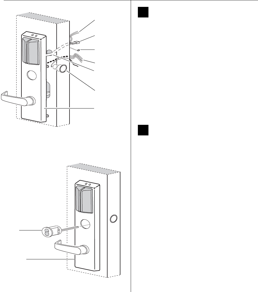
Installation Instructions for Wi-Q Technology™ EXQ Exit Hardware Trim
BEST ACCESS SYSTEMS
a Product Group of Stanley Security Solutions, Inc.
12
Installing the exit hardware and trim
10 Route wire harnesses and position
escutcheon
1 From the outside of the door, feed the antenna wire
and battery connector (with relay shunt) through the
battery bracket/harness hole as shown in Figure 18.
Caution 1: When routing the connectors, make
sure the harnesses are not routed across any
sharp edges or over any surface that could
damage their sleeving or wire insulation.
Caution 2: Do not strain the wire harness either by
pulling too hard on it or by dangling the
escutcheon from it.
2 Route the sensor harness through the door (same hole
as the door sensing wires).
3 Rest the escutcheon on the door by inserting the trim
studs into the mounting holes.
11 Install cylinder (Precision devices)
For rim and vertical rod exit device installations (rim
cylinder)
1 To determine the correct spindle length, try the cylin-
der in the door while holding the escutcheon and lock
stile case in place.
Then break off the spindle at the groove where it will
engage correctly with the latching mechanism.
Break off the mounting screws at the groove where
they will secure the clamp plate to the cylinder.
2 Insert the cylinder through the cylinder opening in the
escutcheon and into the door as shown in Figure 19.
3 Orient the cylinder and clamp plate as shown in
Figure 20. From the inside of the door, secure the cyl-
inder using the clamp plate and mounting screws.
Figure 18 Feeding the wires through the door
Escutcheon
Outside of door
Battery
connector
Battery
bracket/
harness hole
Relay shunt
(Future use)
Antenna
wire
Sensor harness
Door sensing
switch and
wires
Rim
cylinder
Figure 19 Installing the cylinder
Escutcheon
Outside of door
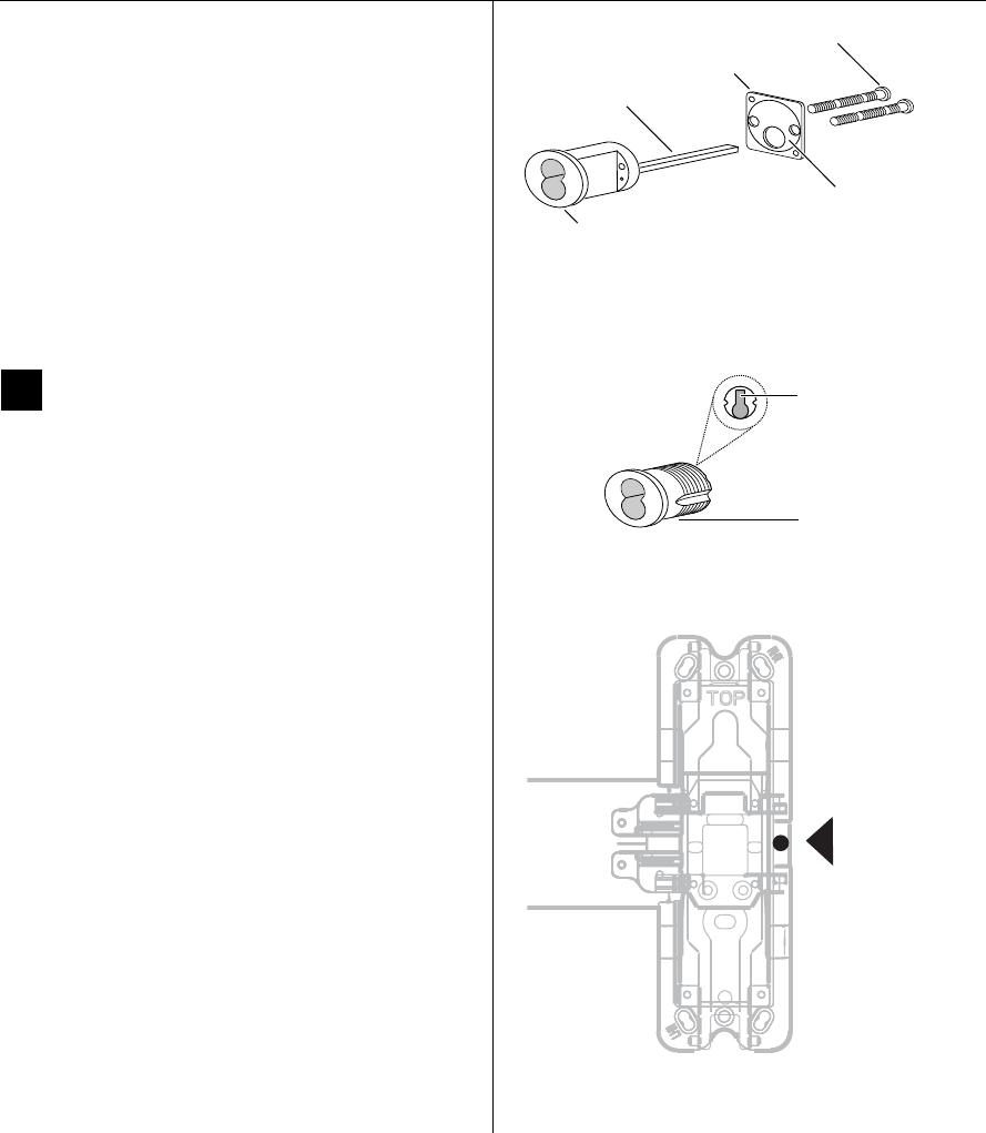
Installation Instructions for Wi-Q Technology™ EXQ Exit Hardware Trim
BEST ACCESS SYSTEMS
a Product Group of Stanley Security Solutions, Inc.
13
Installation Instructions for Wi-Q Technology™ EXQ Exit Hardware Trim
Installing the exit hardware and trim
For mortise exit device installations
(mortise cylinder)
1 For doors less than 2″ in thickness, place the cylin-
der ring provided on the cylinder.
2 Rotate the cylinder cam to the 12 o’clock position, as
shown in Figure 21.
3 Using a cylinder wrench (ED211), insert the cylinder
through the cylinder opening in the escutcheon and
screw the cylinder into the mortise case. Make sure
that the figure-8 hole is in the 12 o’clock position.
Caution: Do not screw the cylinder in too tightly.
Doing so may cause users to be locked out.
12 Install exit hardware and
secure escutcheon
For Precision 2200, 2700 and 2800 exit devices only
■Drill a 5/16” hole through the front part of the chassis
as shown in Figure 22. (This hole is used to pass the
sensor harness and door position switch wires into the
chassis area.)
For all exit devices
1 Make any adjustments to the exit hardware necessary
for compatibility with lever function outside trim.
2 Install the exit hardware (lock stile case, touch bar
assembly, latches and rods [if applicable], and related
hardware); follow the instructions provided by the exit
hardware manufacturer.
Note: The escutcheon is secured on the outside of the
door by the screws used to mount the lock stile case on
the inside of the door.
Caution: When securing the escutcheon, make
sure that it does not pinch any wires.
Figure 20 Rim cylinder components
Rim
cylinder
Screws
Spindle
Clamp plate
Orient the curve
toward the cylinder.
Figure 21 Mortise cylinder components
Mortise cylinder
Cam in 12 o’clock
position
View of the back
of the cylinder
Figure 22 Drilling 5/16” hole for Precision 2200, 2700,
and 2800 exit devices only
Drill 5/16”
hole thru the
face of the
chassis here.
Drill ONLY
for 2200,
2700 and
2800 devices
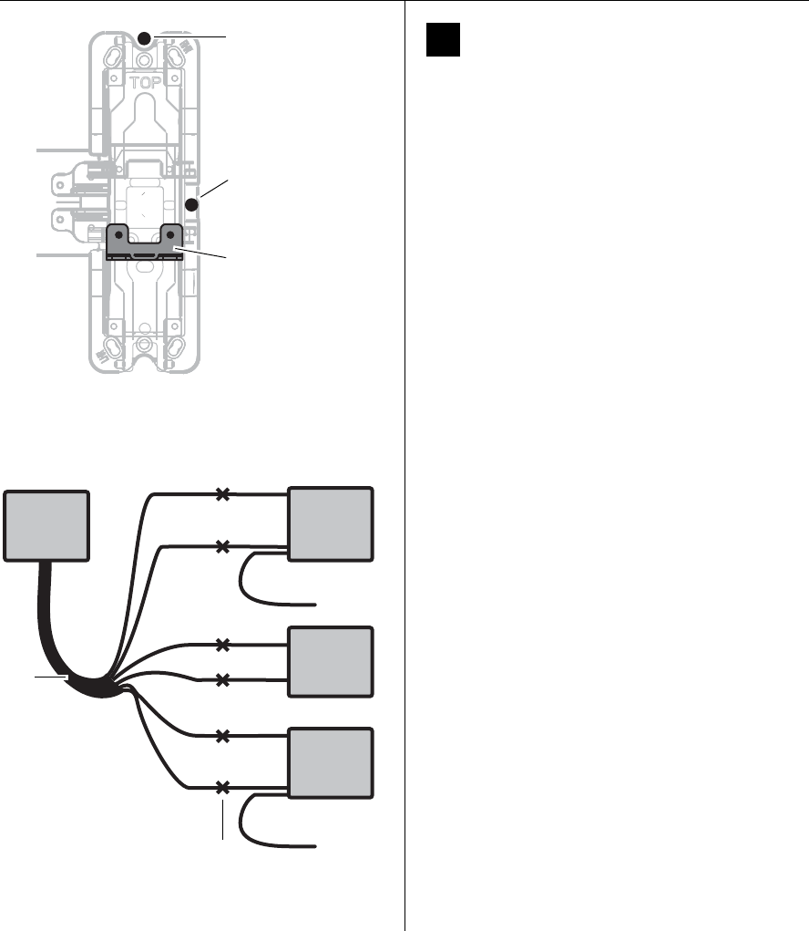
Installation Instructions for Wi-Q Technology™ EXQ Exit Hardware Trim
BEST ACCESS SYSTEMS
a Product Group of Stanley Security Solutions, Inc.
14
Installing the exit hardware and trim
13 Route sensor wires
Use the following table to determine sensing wire
functions:
1 Pull wires from the sensor harness, door position
switch, latchbolt switch, and touchbar switch to the
top of the device head as shown in Figure 23.
Note: For Precision 2300, Sargent 8800, or any Von
Duprin application without RQE, pull the door position
switch and sensor harness wires into the battery bracket
area rather than the device head.
Note: For Von Duprin applications with RQE, touchbar
switch wires must be re-routed into the device head in
such a way as to avoid any pinching or contact with
moving parts. The sensor harness can be routed into the
head area through any suitable hole in the chassis.
2 Cut the wires to the appropriate length (that is,
remove the excess to leave minimal slack after the
spliced connections).
3 Strip the wire ends for connection using the butt-
splices.
4 Make wire connections as detailed in Figure 24 or Fig-
ure 25 using the butt-splices (provided).
Note: For Sargent devices, connect the door position
switch to the two white sensor harness wires.
Note: In the case of unused wires, be sure to cover the
ends with electrical tape.
Wire function Colors No. of
wires
Touchbar monitoring (RQE) Orange and tan 2
Door sensing White 2
Latchbolt sensing Red and blue 2
Figure 23 Pulling sensor harnesses to the top of the
device head
Pull sensor
wires to top of
device head
(shaded area)
Wire entry from
trim for vertical
rod (2200, 2700,
2800) device
Wire entry from
trim for rim
(2100) device
Red Violet
NO
Blue Blue
COM
Wht Wht
Red
NC
Not used
Wht Wht
Org Org
NC
Tan Tan
COM
Latchbolt
switch
EXQ Trim
Door
position
switch
Touchbar
switch
Yellow
NO
Not used
Figure 24 Schematic diagram for connecting Precision
sensor harness wires
Sensor
harness
Butt
splices
NO = Normally Open
NC = Normally Closed
COM = Common
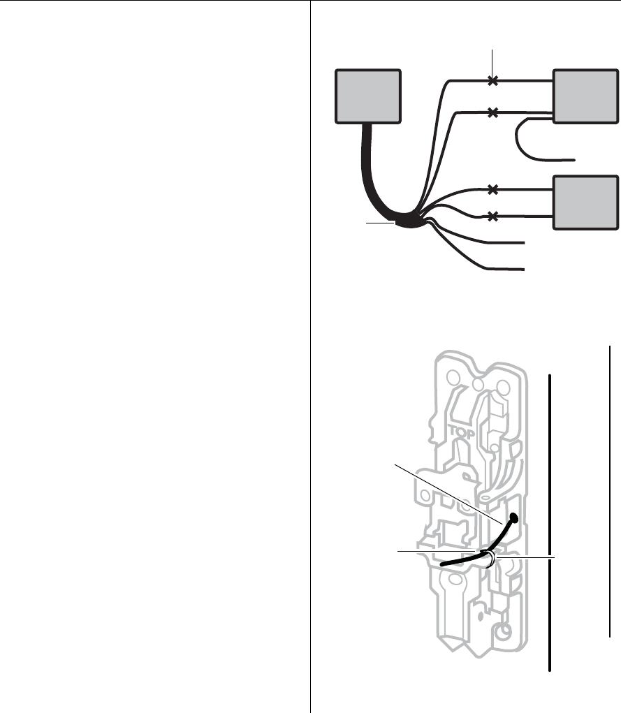
Installation Instructions for Wi-Q Technology™ EXQ Exit Hardware Trim
BEST ACCESS SYSTEMS
a Product Group of Stanley Security Solutions, Inc.
15
Installation Instructions for Wi-Q Technology™ EXQ Exit Hardware Trim
Installing the exit hardware and trim
5 Make sure to route and dress the wires so that they do
not interfere with any moving parts.
6 Tape the wires to the device head (some tape is pro-
vided).
Note: For Precision 2200, 2700, and 2800 exit devices,
use cable ties in addition to the tape, to hold wires as
shown in Figure 26.
7 Install the case cover.
Org
NC
Blue
Tan
COM
Red
Wht Wht
Wht Wht
Red
Blue
Touchbar
switch
EXQ Trim
Door
position
switch
NO
Yellow Not used
Figure 25 Schematic diagram for connecting Von Duprin
sensor harness wires
Butt
splices
Sensor
harness
Not used
}
NO = Normally Open
NC = Normally Closed
COM = Common
TOP
Figure 26 Using cable ties to hold wires for Precision
2200, 2700, and 2800 exit devices
Use cable tie
here to secure
the sensor
harness
Sensor har-
ness coming
thru the 5/16”
hole
described in
Figure 17
Cable tie
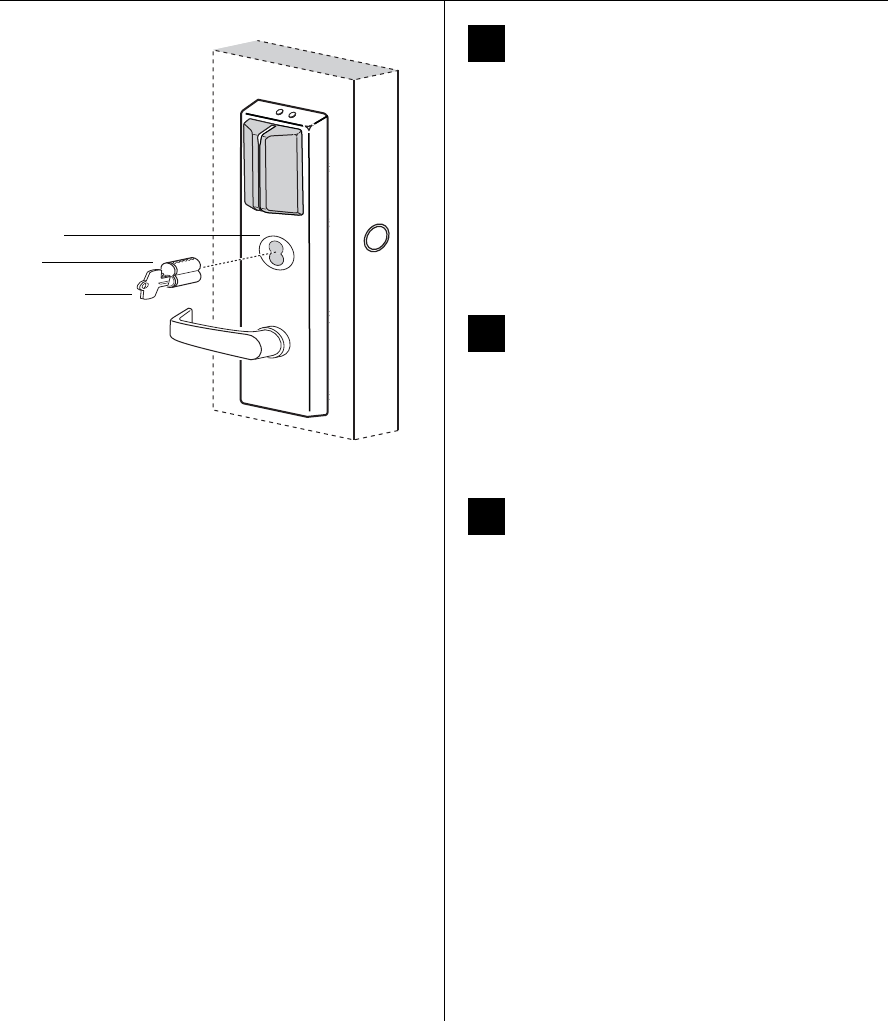
Installation Instructions for Wi-Q Technology™ EXQ Exit Hardware Trim
BEST ACCESS SYSTEMS
a Product Group of Stanley Security Solutions, Inc.
16
Installing the exit hardware and trim
14 Install core
1 Insert the control key into the core and rotate the key
15 degrees to the right.
2 With the control key in the core, insert the core into
the cylinder as shown in Figure 27.
3 Rotate the control key 15 degrees to the left and with-
draw the key.
Caution: The control key can be used to remove
cores and to access doors. Provide adequate secu-
rity for the control key.
15 Install mortise case faceplate
(mortise exit devices only)
1 Secure the mortise case faceplate to the mortise case;
follow the instructions provided by the exit hardware
manufacturer.
2 Check the lock for proper operation.
16 Install strike(s)
Note: If retrofitting the trim to an existing exit hardware
installation, skip this task.
1 Install the strike(s) in the door frame or door stop; fol-
low the instructions provided by the exit hardware
manufacturer.
2 Check the lock for proper alignment between the
strike(s) and latch(es).
Figure 27 Installing the core
Control key
Core
Outside of door
Cylinder
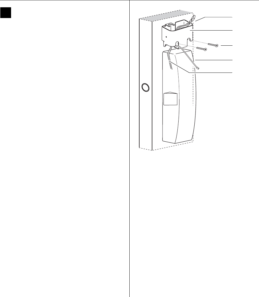
Installation Instructions for Wi-Q Technology™ EXQ Exit Hardware Trim
BEST ACCESS SYSTEMS
a Product Group of Stanley Security Solutions, Inc.
17
Installation Instructions for Wi-Q Technology™ EXQ Exit Hardware Trim
Completing the installation
17 Install battery bracket on door
1 Position the battery bracket on the inside of the door
as shown in Figure 28.
Note: If installing with a surface rod exit device, the bat-
tery bracket is mounted over the upper rod.
2 Secure the battery bracket to the door using two of the
mounting screws provided.
Note: For doors less than 2″ in thickness, use the
1 1/4″ screws. For doors 2″ or greater, use the
1 3/4″ screws.
Caution: When routing the wire harness, make
sure the wires are not routed across any sharp
edges or over any surface that could damage their
sleeving or wire insulation. Keep away from any
moving parts.
3 Tape all wires to the bracket using the tape provided.
Note: For Precision 2300, Sargent 8800, or any Von
Duprin exit device without RQE, sensor harness and door
position switch wires will also be run into this area of the
battery bracket. Figure 28 Installing the battery bracket on the door
Mounting
screws
Inside of door
Battery
bracket
Antenna
wire
Battery
connector
Relay shunt
wires
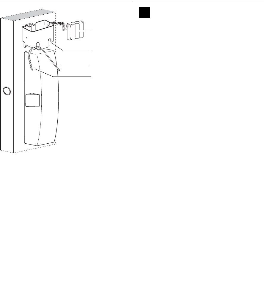
Installation Instructions for Wi-Q Technology™ EXQ Exit Hardware Trim
BEST ACCESS SYSTEMS
a Product Group of Stanley Security Solutions, Inc.
18
Completing the installation
18 Install battery pack in bracket
1 Connect the battery pack to the battery connector on
the wire harness as shown in Figure 29.
Caution: When connecting the battery pack,
make sure:
—there are no loose wire connections where the
wires are inserted into the connectors
—the connectors are firmly mated.
2 Place the battery pack in the holder inside the battery
bracket and dress the wire harness inside the bracket.
Caution: The battery pack fit will be snug. Make
sure you do not damage the sleeving on the bat-
tery pack. Doing so may cause the batteries to
drain.
3 If installing with a surface vertical rod device,
dress the wire harness inside the bracket to the left of
the rod so that the harness will not interfere with the
movement of the rods.
We recommend that you loosely coil the harness and
use a cable tie to secure the coil. To avoid damaging
the harness, do not put any sharp bends in it or flex it
close to the connectors.
Caution: Failure to dress the wire harness away
from the rod could damage the wire harness,
causing the lock’s electronics to not work prop-
erly.
Figure 29 Connecting the battery pack
Battery pack
Inside of door
Battery bracket
Antenna wire
Relay shunt
wires
Installation Instructions for Wi-Q Technology™ EXQ Exit Hardware Trim
BEST ACCESS SYSTEMS
a Product Group of Stanley Security Solutions, Inc.
19
Installation Instructions for Wi-Q Technology™ EXQ Exit Hardware Trim
Completing the installation
19 Install battery/antenna cover
1 If installing with a surface vertical rod exit device,
carefully use a razor blade to remove the knockouts for
the rod from the battery cover. See Figure 30.
2 Connect the antenna to its mating connector.
3 Coil the antenna wire carefully inside the battery
cover.
Caution: Carefully bend, but do not twist or kink
the antenna wire. Doing so may significantly
reduce or completely interrupt signal transmis-
sion.
4 Making sure that the battery/antenna cover does
not pinch any wires, place the battery/antenna cover
over the bracket and battery.
5 Secure the battery cover with the provided self-tap-
ping screws.
Caution: Tighten screws firmly but do not over-
tighten. Over-tightening may strip screw holes or
crack the cover.
Figure 30 Installing the battery cover over the battery
bracket and connecting the antenna
Battery/
antenna cover
Antenna wire
Battery bracket
Carefully bend,
but DO NOT
TWIST OR KINK
the antenna
wire!
Knockout
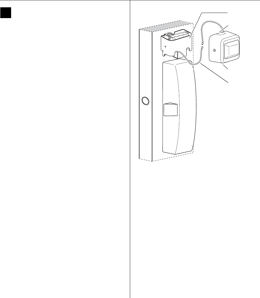
Installation Instructions for Wi-Q Technology™ EXQ Exit Hardware Trim
20
Completing the installation
BEST ACCESS SYSTEMS
a Product Group of Stanley Security Solutions, Inc.
20 Test lock
For EXQ Locks with keypad only:
To test the lock for proper operation before the lock is pro-
grammed, follow these instructions:
1 Press
1234.
2 Press
#.
The green light flashes and the locking mechanism
unlocks.
3 Turn the lever and open the door.
For all other locks:
To test the lock for proper operation before the lock is pro-
grammed, use the temporary operator card that came
with the lock. This card is for temporary use only. After
permanent cards have been programmed for the lock, the
temporary card should be deleted.
1 Use the temporary operator card to activate the lock.
2 Use the temporary operator card to access the lock.
The green light flashes and the locking mechanism
unlocks.
3 Turn the lever or knob and open the door.
4 With the door closed, insert and turn the key to
unlatch the door.
If the mechanism doesn’t unlock, refer to the follow-
ing table.
Important: When the trim and exit hardware
installation is complete, perform all testing specified
by the exit hardware manufacturer.
LEDs Sounder You should
Single red
flash
1 short
tone
Use the card at a
moderate speed.
Single red
flash
3 short
tones
Use the temporary opera-
tor card provided with
the lock.
or
Perform a door reset to
restore to the factory
default settings (the lock
may already be associ-
ated/programmed)
Alternating
red and
green
flashes
none Check the motor
connection.
none none Check the battery
connection.
©2008–2009 Stanley Security Solutions, Inc. and Stanley Logistics, Inc.
T82621/Rev D 3108554 ER-7991-12 April 2009
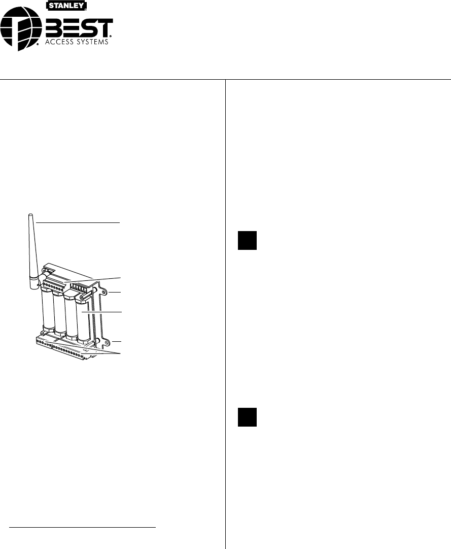
1
BEST ACCESS SYSTEMS
a Product Group of Stanley Security Solutions, Inc.
Introduction
The WQX Wireless Access Controller (WAC) controls
access to one door or access point. It runs on four AA
batteries, or can be externally powered with a DC
power supply. The WAC can be purchased integrated
in a box with power supply or can be purchased stand-
alone. If purchased as a stand-alone unit the power
supply powering the WAC (WQX alone with no other
devices connected) must be able to deliver at least
500mA.
Figure 1 Wireless Access Controller, shown without
cover
Antenna
Mounting hole
Terminals
Four AA
Batteries
Power terminal
Mounting hole
a
Site survey
If a site survey has not been completed, contact your
Stanley Representative.
Components checklist
Use the following checklist to make sure that you have
the items necessary to install your Wireless Access Con-
troller.
a. Power for WAC device only. Calculate power
requirements for attached readers separately.
Components provided in the box
❑Wireless Access Controller with antenna
❑Batteries
❑Documentation
Optional components
❑Indoor ceiling mount omni-directional antenna
❑Indoor wall mount directional antenna
❑Outdoor mount directional antenna
❑Outdoor mount omni-directional antenna
❑Enclosure
1Mount Wireless Access Controller
The standard WAC comes with a small antenna, but
you may need a supplemental antenna for your appli-
cation. See the Site Survey Tool Quick Reference Guide
for more antenna information.
1 Determine the appropriate location for the wireless
single door controller, making sure that the
antenna will have maximum exposure for signal
transmission.
2 Mount the Wireless Access Controller box.
3 Screw on antenna as shown in Figure 1 so that it’s
vertical and upright.
4 Install batteries if needed.
2Install other hardware as necessary
Make sure all other system components are mounted
and installed. System components may include:
■Electronic or electric lock or strike
■Request-to-exit switch
■Power supply for lock or strike
■Reader: either magstripe, proximity, keypad or com-
bination readers. The default reader is a Weigand,
26-bit, 8-bit word type.
Installation Instructions for
Stanley Wi-Q™ Technology
WQX-WAC Wireless Access Controllers

Manufacturer Part number
Stanley 909028065
Indala FP2511A
XceedID XF-1050-B
HID 5355AGK00
Essex KTP-163-SN
Installation Instructions for Stanley Wi-Q™ Technology WQX-WAC Wireless Access Controllers
BEST ACCESS SYSTEMS
a Product Group of Stanley Security Solutions, Inc.
2
Planning the installation
■Sensors: door, latch, deadbolt, key, and/or other.
Note: Some sensors may be included inside the lock.
The BEST 45HW may include door, latch, deadbolt,
and key sensors.
3Pull wire and make connections to
wireless access controller
1 Determine what connections you need to make
based on your application.
2 Using Figure 2 and Table 1 make the connections.
Table 1 WAC Connections and descriptions
Terminal Description
Strike NC
Normally-closed terminal
where the locking mechanism
connects
Strike COM
Common return path for cur-
rent through the locking mech-
anism
Strike NO
Normally-open terminal where
the locking mechanism con-
nects
SHUNT NC
Normally-closed relay terminal
that shunts door force alarm if
access is granted or RQE is acti-
vated
SHUNT COM Return path for the shunt relay
SHUNT NO Normally-open terminal for the
shunt relay
KEY Detects and reports a key-over-
ride event
GND Return path for the key-over-
ride switch and RQE
RQE Request-to-exit input
DS Door status input
GND Return path for door status and
latch status
LS Latch status input
WIEGAND 0 Wiegand D0 terminal
GND
Ground (the wiegand reader
must be grounded at this
point)
WIEGAND1 Wiegand D1 terminal
RED Red LED control input
GND LED ground point
GRN Green LED control input
ANT Antenna connection
Negative DC
terminal
Power connection
Negative DC
terminal
Power connection. Use the
extra negative DC terminal to
‘daisy-chain’ power to another
wireless access controller or
reader.a
a. Make sure the power supply is of appropriate
wattage to supply enough power.
Positive DC 9–24V
terminal
Power connection
Positive DC 9–24V
terminal
Power connection. Use the
extra positive DC terminal to
‘daisy-chain’ power to another
wireless access controller or
reader.a
Important note: When using the WAC to daisy-chain
other devices, be sure that the other devices will
accept the voltage supplied to the WAC.
Table 1 WAC Connections and descriptions
Terminal Description
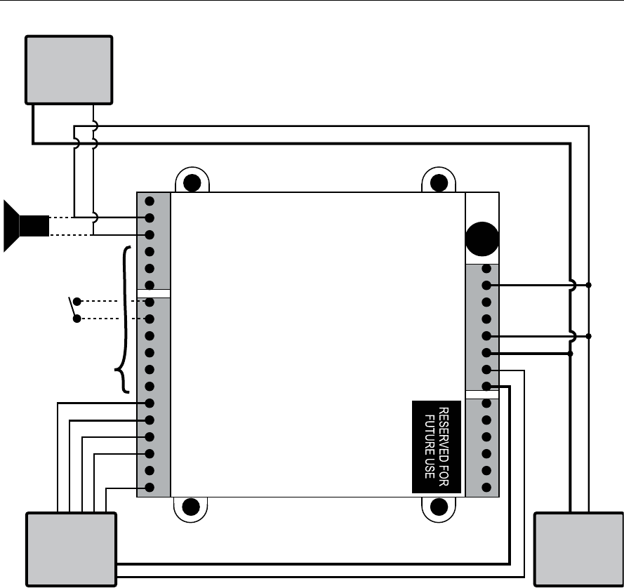
Figure 2 Wireless Access Controller, typical installation.
See Table 1 for a description of connections.
Weigand
output
reader
12 VDC
Strike Power
Supply
by others
Electric
lock, strike
or maglock
STRIKE NC (Relay 1)
STRIKE COM (Relay 1)
STRIKE NO (Relay 1)
SHUNT NC (Relay 2)
SHUNT COM (Relay 2)
SHUNT NC (Relay 2)
KEY (I/O)
GND
RQE (I/O)
DSM (I/O)
GND
DLS (I/O)
WIEGAND 0 (I/O)
GND
WIEGAND 1 (I/O)
RED
GND
GRN
ANT
DO NOT USE
GND
3.3V (10mA MAX)
DO NOT USE
– DC 9-24V
+ DC 9-24V
– DC 9-24V
+ DC 9-24V
+12 VDC
Connect
as required
Output
device (example
shown: horn)
Input switch
GND
(–)
(+)
(+ Power)
(+ Power)
Installation Instructions for Stanley Wi-Q™ Technology WQX-WAC Wireless Access Controllers
3
Installation Instructions for Stanley Wi-Q™ Technology WQX-WAC Wireless Access Controllers
Planning the installation
BEST ACCESS SYSTEMS
a Product Group of Stanley Security Solutions, Inc.

Installation Instructions for Stanley Wi-Q™ Technology WQX-WAC Wireless Access Controllers
BEST ACCESS SYSTEMS
a Product Group of Stanley Security Solutions, Inc.
4
Planning the installation
4Sign on WAC
The process of bringing a WAC into the Stanley Wi-Q™
Access Management System (AMS) is known as signing
on.
If the connected reader doesn’t have a keypad, a sign-
on keypad is required. If no wired keypad is installed, a
sign-on keypad is available as accessory WQD-WAC-
PAD.
Connect the sign-on keypad to the WAC Wireless
Access Controller
1 Once the WAC is wired, connect the sign-on keypad
to the WAC reader terminal.
Signing on a WAC Wireless Access Controller
2 Enter 5678 on the keypad.
This will cause the green LED to blink the on the WAC
three times.
3 Enter the sign-on key for the facility in the AMS
database.
Note: The sign-on key can be found under the facility
sign-on credential field in the Wi-Q Technology™
Access Management System (AMS). Refer to the Stan-
ley Wi-Q AMS User Guide.
You should see the red and green LEDs blinking and
the blue light turns ON to indicate that the radio on
the board is active. Once the reader signs on to one of
the portal gateways in your facility, the green LED on
the WAC blinks three times. At this point the WAC
should appear under the New Facility Item folder in
AMS (it may take up to 2 minutes for this to occur).
5Test WAC
For Wireless Access Controller with keypad only:
To test the WAC for proper operation before It’s pro-
grammed, follow these instructions:
1 Press 1234.
2 Press #.
The green light flashes and the locking mechanism
unlocks or you should hear a relay click.
3 Operate the lock and open the door.
For Wireless Access Controllers wired to card
readers:
To test the lock for proper operation before the lock is
programmed, use the temporary operator card that
came with the device. This card is for temporary use
only. After permanent cards have been programmed
into the device, the temporary card will no longer
unlock the lock (once users are programmed into the
WAC).
1 Using the installed reader to access the lock, pres-
ent the temporary operator card to gain access.
The green light flashes and the locking mechanism
unlocks.
If the mechanism doesn’t unlock, use the on-board
LEDs and refer to the following table.
WAC
on-board
LEDs
You should
Single red
flash
Use the card at a moderate speed.
Three red
flashes
Use the temporary operator card
provided with the lock.
or
Perform a deep reset to restore to
the factory default settings (the lock
may already be associated/pro-
grammed)
Installation Instructions for Stanley Wi-Q™ Technology WQX-WAC Wireless Access Controllers
5
Installation Instructions for Stanley Wi-Q™ Technology WQX-WAC Wireless Access Controllers
Planning the installation
BEST ACCESS SYSTEMS
a Product Group of Stanley Security Solutions, Inc.
Resetting the WAC
The WAC has two reset functions:
■Soft reset – restores previous functionality. Use this
under normal operation. It will reset the WAC, but
DOES NOT ERASE USERS.
■Hard reset – restores factory settings. Use this reset
only when moving the WAC or after exhausting all
other troubleshooting options.
none Check the battery connection.
no blue
light
Reset. Sign-on the WAC using the
sign-on procedure.
LEDs You should
Single red
flash
Use the card at a moderate
speed.
Three red
flashes
Use the temporary operator
card provided with the lock.
WAC
on-board
LEDs
You should
Using the soft reset function
■Hold the reset button until the green LED flashes
five times and then release. See Figure 3.
Lights will alternate red/green rapidly.
The WAC is restored to its previous functionality
Using the hard reset function
Caution: Use this procedure only to restore the
factory default settings. Performing these steps
will erase all user data that may have been
programmed into the WAC.
■Hold the reset button for up to 30 seconds — until
the green LED flashes and then the red LED flashes
three times. Then release. See Figure 3.
All users are erased and the WAC is restored to its
factory default settings.
Figure 3 Using the reset button
Reset
button
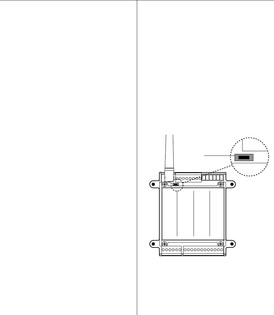
Installation Instructions for Stanley Wi-Q™ Technology WQX-WAC Wireless Access Controllers
BEST ACCESS SYSTEMS
a Product Group of Stanley Security Solutions, Inc.
4
Planning the installation
4Sign on WAC
The process of bringing a WAC into the Stanley Wi-Q™
Access Management System (AMS) is known as signing
on.
If the connected reader doesn’t have a keypad, a sign-
on keypad is required. If no wired keypad is installed, a
sign-on keypad is available as accessory WQD-WAC-
PAD.
Connect the sign-on keypad to the WAC Wireless
Access Controller
1 Once the WAC is wired, connect the sign-on keypad
to the WAC reader terminal.
Signing on a WAC Wireless Access Controller
2 Enter 5678 on the keypad.
This will cause the green LED to blink the on the WAC
three times.
3 Enter the sign-on key for the facility in the AMS
database.
Note: The sign-on key can be found under the facility
sign-on credential field in the Wi-Q Technology™
Access Management System (AMS). Refer to the Stan-
ley Wi-Q AMS User Guide.
You should see the red and green LEDs blinking and
the blue light turns ON to indicate that the radio on
the board is active. Once the reader signs on to one of
the portal gateways in your facility, the green LED on
the WAC blinks three times. At this point the WAC
should appear under the New Facility Item folder in
AMS (it may take up to 2 minutes for this to occur).
5Test WAC
For Wireless Access Controller with keypad only:
To test the WAC for proper operation before It’s pro-
grammed, follow these instructions:
1 Press 1234.
2 Press #.
The green light flashes and the locking mechanism
unlocks or you should hear a relay click.
3 Operate the lock and open the door.
For Wireless Access Controllers wired to card
readers:
To test the lock for proper operation before the lock is
programmed, use the temporary operator card that
came with the device. This card is for temporary use
only. After permanent cards have been programmed
into the device, the temporary card will no longer
unlock the lock (once users are programmed into the
WAC).
1 Using the installed reader to access the lock, pres-
ent the temporary operator card to gain access.
The green light flashes and the locking mechanism
unlocks.
If the mechanism doesn’t unlock, use the on-board
LEDs and refer to the following table.
WAC
on-board
LEDs
You should
Single red
flash
Use the card at a moderate speed.
Three red
flashes
Use the temporary operator card
provided with the lock.
or
Perform a deep reset to restore to
the factory default settings (the lock
may already be associated/pro-
grammed)
Installation Instructions for Stanley Wi-Q™ Technology WQX-WAC Wireless Access Controllers
5
Installation Instructions for Stanley Wi-Q™ Technology WQX-WAC Wireless Access Controllers
Planning the installation
BEST ACCESS SYSTEMS
a Product Group of Stanley Security Solutions, Inc.
Resetting the WAC
The WAC has two reset functions:
■Soft reset – restores previous functionality. Use this
under normal operation. It will reset the WAC, but
DOES NOT ERASE USERS.
■Hard reset – restores factory settings. Use this reset
only when moving the WAC or after exhausting all
other troubleshooting options.
none Check the battery connection.
no blue
light
Reset. Sign-on the WAC using the
sign-on procedure.
LEDs You should
Single red
flash
Use the card at a moderate
speed.
Three red
flashes
Use the temporary operator
card provided with the lock.
WAC
on-board
LEDs
You should
Using the soft reset function
■Hold the reset button until the green LED flashes
five times and then release. See Figure 3.
Lights will alternate red/green rapidly.
The WAC is restored to its previous functionality
Using the hard reset function
Caution: Use this procedure only to restore the
factory default settings. Performing these steps
will erase all user data that may have been
programmed into the WAC.
■Hold the reset button for up to 30 seconds — until
the green LED flashes and then the red LED flashes
three times. Then release. See Figure 3.
All users are erased and the WAC is restored to its
factory default settings.
Figure 3 Using the reset button
Reset
button
Installation Instructions for Stanley Wi-Q™ Technology WQX-WAC Wireless Access Controllers
6BEST ACCESS SYSTEMS
a Product Group of Stanley Security Solutions, Inc.

Stanley Omnilock
a Product Group of Stanley Security Solutions, Inc.
1
Planning the installation
T83303/Rev C 3132330 ER-7991-12 Mar 2011
Contents
These installation instructions describe how to install
your 9KOM Cylindrical Lock. Topics covered include:
Planning the installation.............................................. 1
Preparing the door and door jamb............................. 2
Installing the lock .......................................................... 7
Completing the installation......................................... 9
Site survey
Use the following survey to record information about
the installation site. You need this information to deter-
mine how to prepare the door for the lock.
Door information
Door handing and bevel:
❐ Left hand (LH)
❐ Left hand, reverse bevel (LHRB)
❐ Right hand (RH)
❐ Right hand, reverse bevel (RHRB)
Door thickness: 1-3/4 to 2 inches (44 to 50 mm). If other
than 1 3/4” (44 mm), see “Optional: Adjust for door
thickness” on page 6.
Environment information
a. See Stanley installation instruction Addendum (T83317) Extreme
Weatherized Installation for the extreme weatherized model.
Model Side of
door
Temperature
Range Exposure
Standard Outside +32°F to +129°F
0°C to +54°C
Drip proof. Inad-
vertent water
splash accepted.
Weatherized Outside -4°F to +129°F
-20°C to +54°C
Direct exposure to
rain and snow
Extreme
Weatherized a
Outside -40°F to +129°F
-40°C to + 54°C
Direct exposure to
rain and snow
Inside +32°F to +129°F
0°C to +54°C N/A
Components checklist
Use the following checklist to make sure that you have
the items necessary to install your Electronic Stand-
alone Cylindrical Lock.
Components provided in the box:
❐ Outside lever
❐ Inside lever
❐ Throw member package
❐ Latch
❐ Strike package
❐ Through-bolt screws
❐ Installation template and instructions
❐ Four AA size batteries (or 2 weatherized packs)
Other components:
❐ Programming Default ID Card (provided with
software)
Special tools checklist
Use the following checklist to make sure that you have
the special tools necessary to install your Electronic
Stand-alone Cylindrical Lock.
❐ KD303 Drill jig
❐ KD325 Strike plate locating pin
❐ KD315 Faceplate marking chisel
Installation Instructions for
Stanley Omnilock 9KOM
Cylindrical Locks
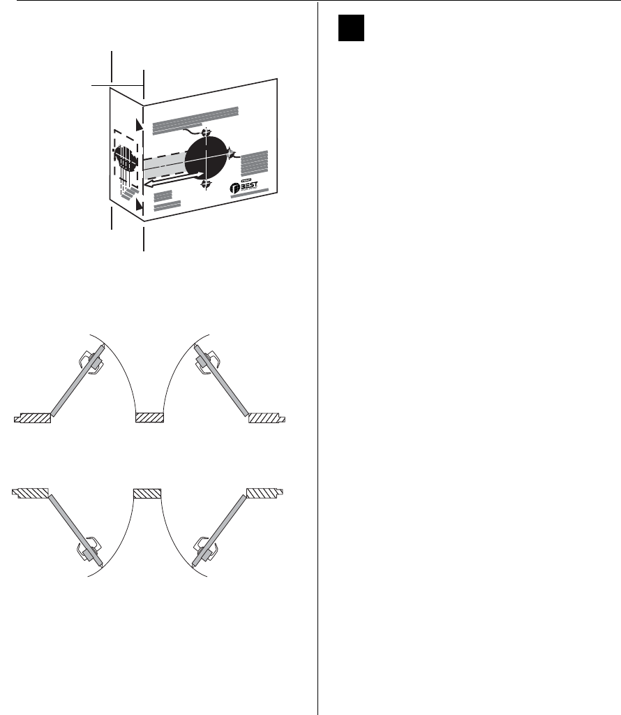
Installation Instructions for Stanley Omnilock 9KOM Cylindrical Locks
Stanley Omnilock
a Product Group of Stanley Security Solutions, Inc.
2
Preparing the door and door jamb
1Position template and mark drill
points
Note: If the door is a fabricated hollow metal door,
determine whether it is properly reinforced to
support the lock. If door reinforcement is not
adequate, consult the door manufacturer for
information on proper reinforcement. For
dimensions for preparing metal doors for locks with
2 3/4” (70 mm) backset, see Template T56052 or
T56053 Door and Frame Preparation for 63K, 73KC,
83K, and 93K Cylindrical Locks.
Note 1: If the door is a LH or RH door, mark the
inside of the door. If the door is a LHRB or RHRB door,
mark the outside of the door. See Figure 2.
Note 2: For Extreme Weatherized model template,
see Installation Addendum for Stanley Omnilock
9KOM Extreme Weatherized Locks (T83319).
For uncut doors and frames
1 Measure and mark the horizontal centerline of the
lever (the centerline for the chassis hole) on the
door and door jamb. Mark the vertical centerline
of the door edge.
Note: The recommended height from the floor to
the centerline of the lock (centerline of 2 1/8” (54
mm) hole) is 40 5/16” (1024 mm).
2 Fold the template on the dashed line and
carefully place it in position on the high side of
the door bevel as shown in Figure 1.
Note: For steel frame applications, align the
template’s horizontal centerline for the latch with
the horizontal centerline of the frame’s strike
preparation.
3 Tape the template to the door.
4 Center punch the necessary drill points. Refer to
the instructions on the template.
Template for 2 3/4
"
Backset
6K, 7KC, 8K and 9K Cylindrical Locks with RQE
Figure 1 Positioning the template
High edge of
door bevel
Outside
Outside
Left hand (LH) Right hand (RH)
Left hand
reverse bevel
(LHRB)
Right hand
reverse bevel
(RHRB)
Figure 2 Door handing chart
Left hand (LH) Outside Right Hand (RH)
Left hand
reverse bevel
(LHRB)
Outside
Right hand
(RHRB)
reverse bevel
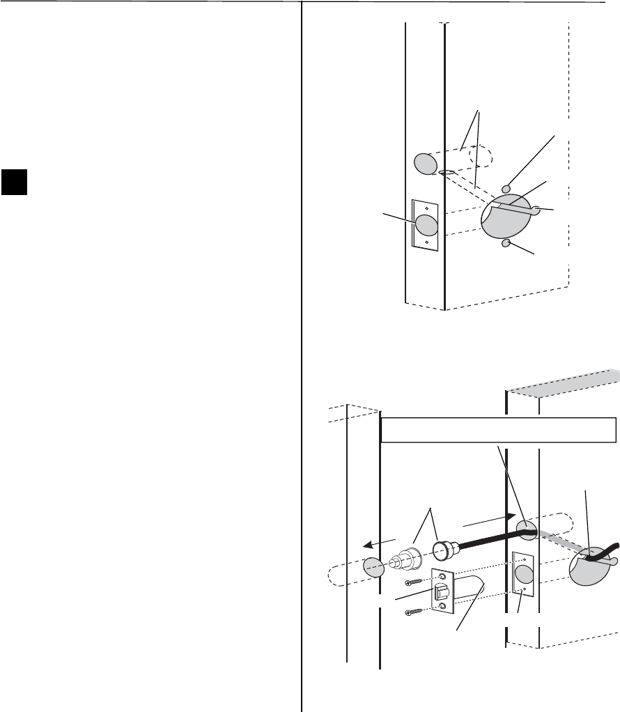
Installation Instructions for Stanley Omnilock 9KOM Cylindrical Locks
Stanley Omnilock
a Product Group of Stanley Security Solutions, Inc.
3
Installation Instructions for Stanley Omnilock 9KOM Cylindrical Locks
Preparing the door and door jamb
For doors with standard cylindrical preparation
1 Fold the template on the dashed line. Looking
through the hole from the opposite side of the
door, align the template so that you see the
template outline of the 2 1/8” (54 mm) diameter
chassis hole.
2 Tape the template to the door and enter punch the
necessary drill points.
2Drill holes and mortise for latch face
Note: To locate the center of a hole on the opposite
side of the door, drill a pilot hole completely through
the door.
1 Drill the holes in order listed below:
■ motor wire hole
◆ 7/16” (11 mm) diameter through door
◆ always drill before drilling chassis hole
■ chassis hole
◆ 2 1/8” (54 mm) diameter through door
◆ drill after drilling motor wire hole
■ latch hole
◆ 1” (25 mm) diameter
◆ meets chassis hole
■(OPTIONAL) Door Status Switch
◆ 1” (25 mm) diameter on door
◆ 1” (25 mm) diameter on jamb
◆ 1-3/4” (44mm) deep on door
◆ 1” (25 mm) deep on jamb
Note: The latch tube prongs should be centered and
should project into the chassis hole.
2 Mortise the edge of the door to fit the latch face.
3 Drill the holes for the latch screws.
4 Install the latch in the door as shown in Figure 4.
5 For optional door status switch: Position the bit
inside the hole. Then drill a 3/8” (10mm) channel at
an angle that will connect the door status switch
hole to the chassis hole as shown in Figure 4.
6 Press fit both switch pieces as shown in Figure 4.
7 Check that the door swings freely.
Figure 3 Drilling holes and mortising for the latch face
Latch hole
Inside of door
Optional door status
switch holes
Mounting hole
Chassis hole
Motor wire
notch
Mounting hole
Figure 4 Installing the latch in the door
Location of latch
tube prongs
Chassis hole
Inside of door
Optional door
status switch
Caution: Make sure the wires are not routed across any sharp
edges or over any surface that could damage the sleeving.
Latch mortise
Latch
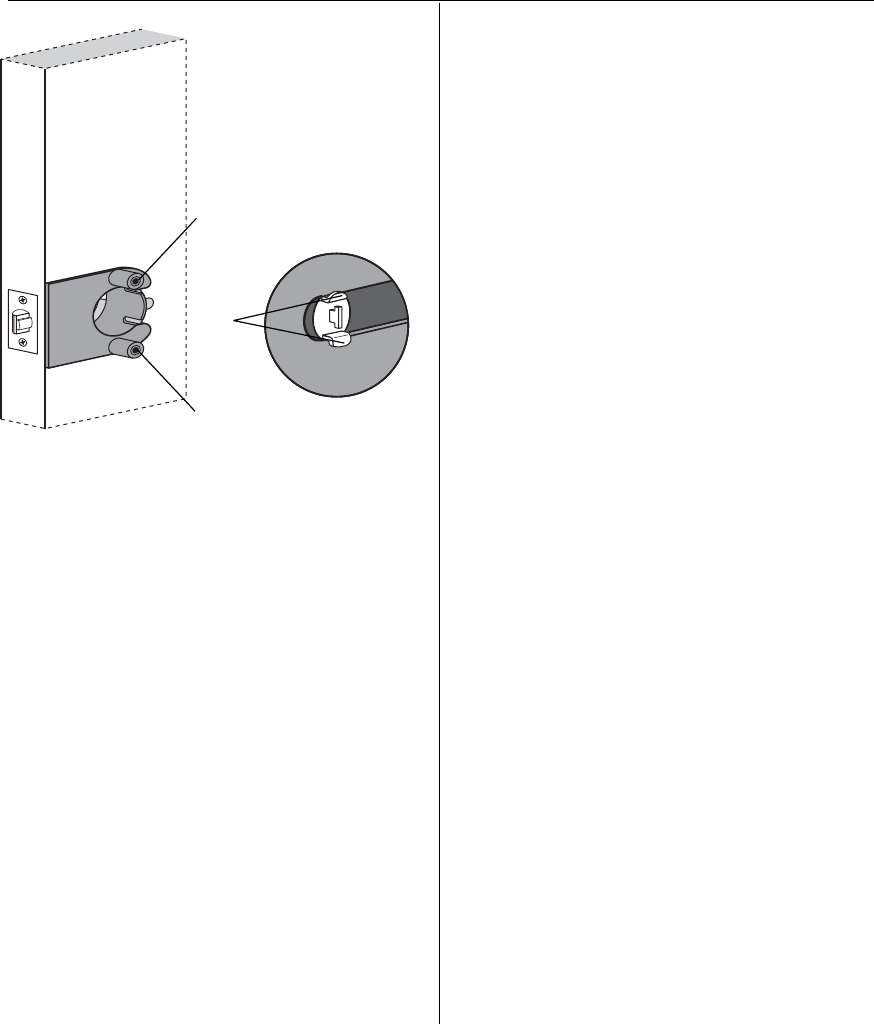
Installation Instructions for Stanley Omnilock 9KOM Cylindrical Locks
Stanley Omnilock
a Product Group of Stanley Security Solutions, Inc.
4
Preparing the door and door jamb
Use drill jig to drill through-bolt holes
1 Press the drill jig (KD303) onto the door, engaging
it with the latch tube prongs (see the close-up in
Figure 5). Make sure the front edge of the jig is
parallel with the door edge.
2 Drill the through-bolt holes (5/16(8 mm)
diameter) halfway into the door.
3 Turn over the drill jig and repeat steps 1 and 2
from the opposite side of the door.
Note 2: Replace the drill jig after 10 door
preparations.
Figure 5 Installing the drill jig and drilling the
through-bolt holes
Latch
tube
prong
Drill upper through-bolt hole.
Drill lower through-bolt hole.
Inside of door
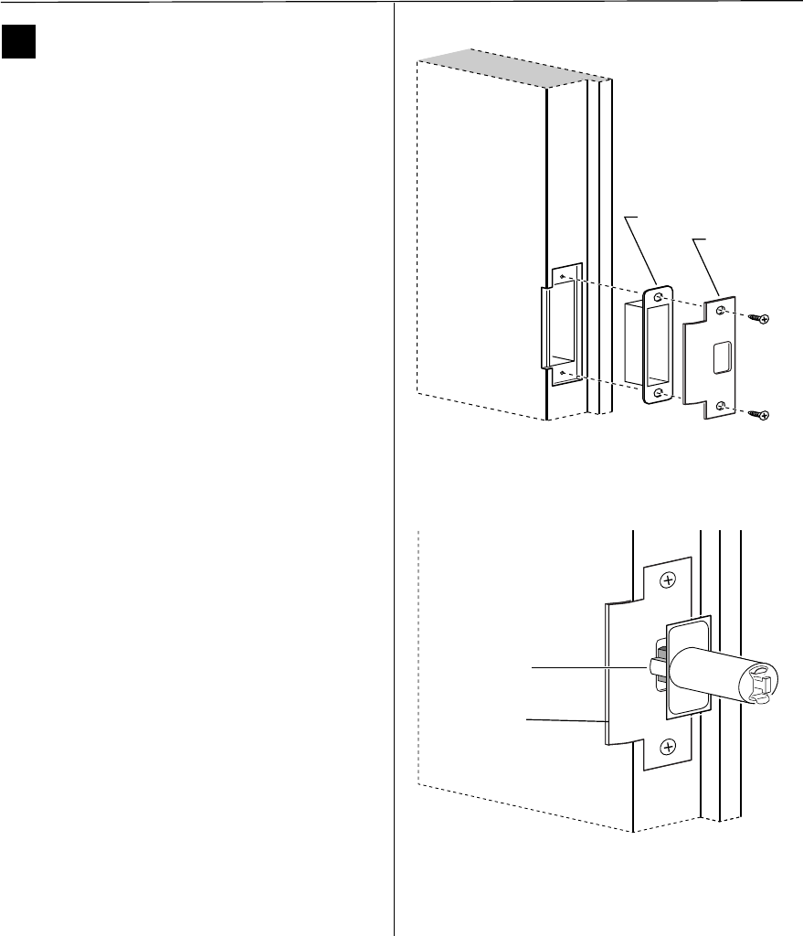
Installation Instructions for Stanley Omnilock 9KOM Cylindrical Locks
Stanley Omnilock
a Product Group of Stanley Security Solutions, Inc.
5
Installation Instructions for Stanley Omnilock 9KOM Cylindrical Locks
Preparing the door and door jamb
3Install strike box and strike plate
1 Align with the center of the latchbolt, then
mortise the door jamb to fit the strike box and
strike plate. See Figure 6.
2 Drill the holes for the screws used to install the
strike box and strike plate.
3 Insert the strike box and secure the strike with the
two screws provided.
4 Check the position of the deadlocking plunger
against the strike plate.
Caution: The deadlocking plunger of the
latchbolt must make contact with the strike
plate, as shown in Figure 7. The plunger
deadlocks the latchbolt and helps prevent
someone from forcing the latch open when
the door is closed.
Figure 6 Installing the strike box and strike plate
Strike box
Strike plate
Door jamb
Figure 7 Aligning the deadlocking plunger with the
strike plate
Strike plate
Deadlocking
plunger
Door jamb
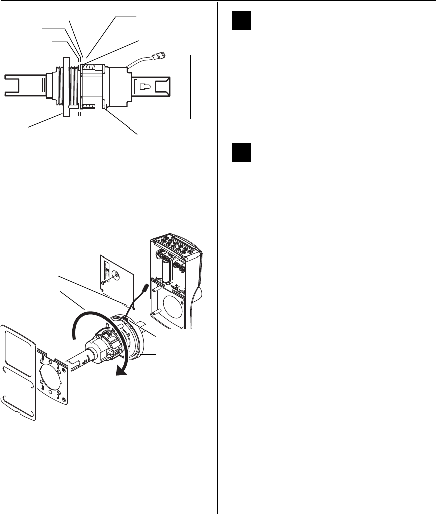
Installation Instructions for Stanley Omnilock 9KOM Cylindrical Locks
Stanley Omnilock
a Product Group of Stanley Security Solutions, Inc.
6
Preparing the door and door jamb
4Optional: Adjust for door thickness
Note: The default door thickness is 1 3/4” (44 mm).
If your door is thicker than 1 3/4” (44 mm), use the
following instructions.
1 Determine the door’s thickness.
2 Pull the rose locking pin and rotate the outside
rose liner until the proper groove on the
through-bolt stud lines up with the hub face. See
Figure 8.
5Optional: Adjust handing
Note: This is required only if the lock hand does not
meet your application. The lockset is normally
preset for a right-hand door. Verify the handing of
the lock per Figure 2 and, if required, change the
handing of the lock.
1 In order: remove the gasket, battery cover, and
back plate. See Figure 9.
2 Remove the chassis.
3 Rotate the chassis 180 degrees clockwise (looking
at the back or opposite the latch).
Note: Do not pull the wire.
4 Pry off the rose that holds the wire in place.
5 Re-route the wire back through the opening in
the rose.
6 Press the rose back on.
7 Reinstall the chassis.
Figure 8 Adjusting the rose liner for the door
1 3/4” (44 mm)
2” (51 mm)
2 1/4” (57 mm)groove Through-bolt stud
Hub face
Outside
rose liner Rose locking pin
Motor wire
Figure 9 Adjusting the rose liner for the door
Gasket
Battery cover
Back plate
Rotate chassis
180 degrees
clockwise
Rose
Re-route wire
Opening
Installation Instructions for Stanley Omnilock 9KOM Cylindrical Locks
Stanley Omnilock
a Product Group of Stanley Security Solutions, Inc.
7
Installation Instructions for Stanley Omnilock 9KOM Cylindrical Locks
Installing the lock
6Install batteries
Four alkaline AA batteries (or two weatherized packs,
if installing a weatherized unit) are furnished with
your Omnilock system and must be installed before
proceeding.
Note: For the Extreme Weatherized model, see
Installation Addendum for Stanley Omnilock 9KOM
Extreme Weatherized Locks (T83319) for battery
and escutcheon installation.
1 Remove the gasket from the rear of the housing
assembly as shown in Figure 10.
2 Remove the screw from the battery cover and
remove the cover.
3 Install batteries with proper polarity as shown in
Figure 11. (For weatherized battery packs, simply
connect the wires from the battery pack to the
circuit board as shown in Figure 12.)
Note: Be sure red and black motor wires are
connected before attempting step 4. Align the wires
together so that the wire colors match.
4 Press and hold the reset button on the PC board
(as shown in Figure 11) until the green light on
the keypad flashes (about three seconds), then
release the button. If the green light does not
flash see “Troubleshooting” on page 10.
5 Replace the battery cover. See Figure 10. Make
sure that the tabs on the lower edge of the
battery cover are hooked over the edge of the
back plate and secure the cover with the screw.
6 Replace the gasket. See Figure 10. Make sure that
it is inside the edge of the housing.
7 A label on the housing assembly battery cover
indicates the magnetic card track (track 2 or track
3) that the system is set to read. See Figure 10.
Figure 10 Installing batteries
Housing assembly
AA Batteries
Back plate
Battery cover
Gasket
Pan head
Track setting
label
Reset button
Motor connector
Red wire
Black wire
Terminal block
Figure 11 Using the reset button
Figure 12 Weatherized battery packs
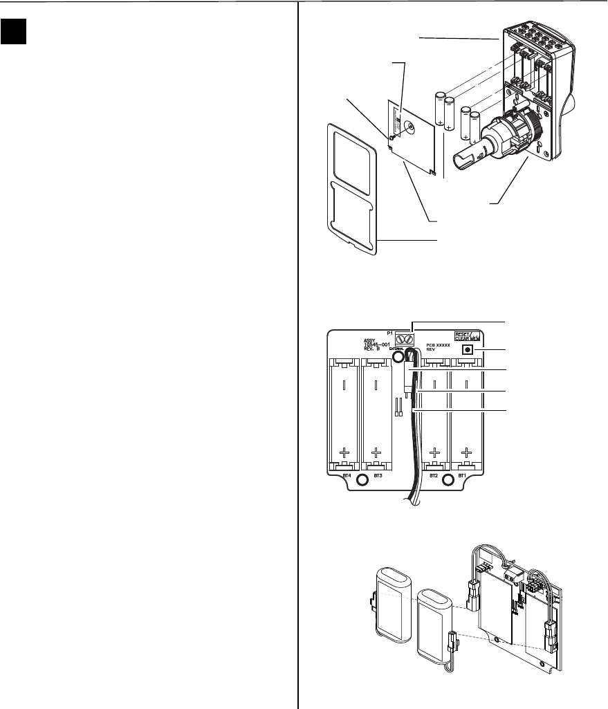
Installation Instructions for Stanley Omnilock 9KOM Cylindrical Locks
Stanley Omnilock
a Product Group of Stanley Security Solutions, Inc.
6
Preparing the door and door jamb
4Optional: Adjust for door thickness
Note: The default door thickness is 1 3/4” (44 mm).
If your door is thicker than 1 3/4” (44 mm), use the
following instructions.
1 Determine the door’s thickness.
2 Pull the rose locking pin and rotate the outside
rose liner until the proper groove on the
through-bolt stud lines up with the hub face. See
Figure 8.
5Optional: Adjust handing
Note: This is required only if the lock hand does not
meet your application. The lockset is normally
preset for a right-hand door. Verify the handing of
the lock per Figure 2 and, if required, change the
handing of the lock.
1 In order: remove the gasket, battery cover, and
back plate. See Figure 9.
2 Remove the chassis.
3 Rotate the chassis 180 degrees clockwise (looking
at the back or opposite the latch).
Note: Do not pull the wire.
4 Pry off the rose that holds the wire in place.
5 Re-route the wire back through the opening in
the rose.
6 Press the rose back on.
7 Reinstall the chassis.
Figure 8 Adjusting the rose liner for the door
1 3/4” (44 mm)
2” (51 mm)
2 1/4” (57 mm)groove Through-bolt stud
Hub face
Outside
rose liner Rose locking pin
Motor wire
Figure 9 Adjusting the rose liner for the door
Gasket
Battery cover
Back plate
Rotate chassis
180 degrees
clockwise
Rose
Re-route wire
Opening
Installation Instructions for Stanley Omnilock 9KOM Cylindrical Locks
Stanley Omnilock
a Product Group of Stanley Security Solutions, Inc.
7
Installation Instructions for Stanley Omnilock 9KOM Cylindrical Locks
Installing the lock
6Install batteries
Four alkaline AA batteries (or two weatherized packs,
if installing a weatherized unit) are furnished with
your Omnilock system and must be installed before
proceeding.
Note: For the Extreme Weatherized model, see
Installation Addendum for Stanley Omnilock 9KOM
Extreme Weatherized Locks (T83319) for battery
and escutcheon installation.
1 Remove the gasket from the rear of the housing
assembly as shown in Figure 10.
2 Remove the screw from the battery cover and
remove the cover.
3 Install batteries with proper polarity as shown in
Figure 11. (For weatherized battery packs, simply
connect the wires from the battery pack to the
circuit board as shown in Figure 12.)
Note: Be sure red and black motor wires are
connected before attempting step 4. Align the wires
together so that the wire colors match.
4 Press and hold the reset button on the PC board
(as shown in Figure 11) until the green light on
the keypad flashes (about three seconds), then
release the button. If the green light does not
flash see “Troubleshooting” on page 10.
5 Replace the battery cover. See Figure 10. Make
sure that the tabs on the lower edge of the
battery cover are hooked over the edge of the
back plate and secure the cover with the screw.
6 Replace the gasket. See Figure 10. Make sure that
it is inside the edge of the housing.
7 A label on the housing assembly battery cover
indicates the magnetic card track (track 2 or track
3) that the system is set to read. See Figure 10.
Figure 10 Installing batteries
Housing assembly
AA Batteries
Back plate
Battery cover
Gasket
Pan head
Track setting
label
Reset button
Motor connector
Red wire
Black wire
Terminal block
Figure 11 Using the reset button
Figure 12 Weatherized battery packs
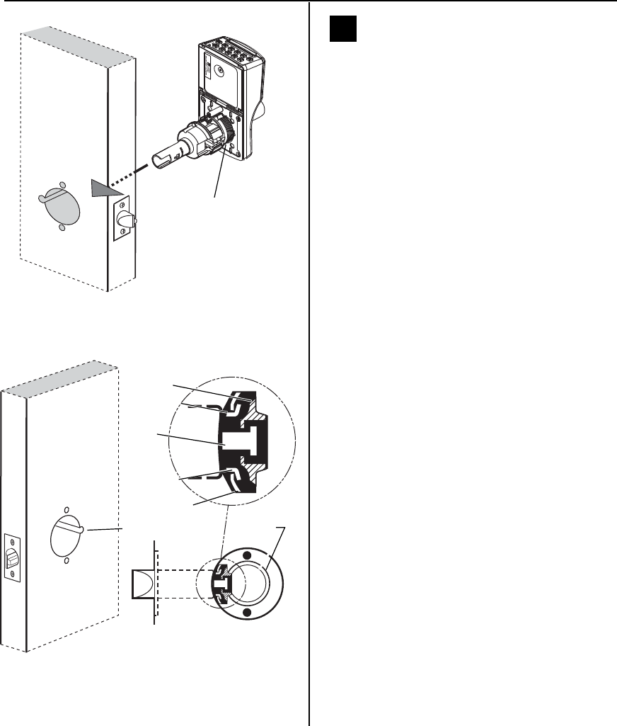
Installation Instructions for Stanley Omnilock 9KOM Cylindrical Locks
Stanley Omnilock
a Product Group of Stanley Security Solutions, Inc.
8
Installing the lock
7Install outside escutcheon and lock
chassis and engage retractor in
latch
1 From the outside of the door, insert the lock
chassis and outside escutcheon into the 2 1/8” (54
mm) chassis hole. See Figure 13.
2 Make sure that the latch tube prongs engage the
chassis frame and that the latch tailpiece engages
the retractor. See Figure 14.
Figure 13 Installing the outside escutcheon and lock
chassis
Inside of door
Outside escutcheon
and chassis
Figure 14 Installing the lock chassis and engaging the
retractor in the latch
Latch tube
prong
Retractor
Latch
tailpiece
Chassis
Chassis frame
Latch tube
prong
Notch
Installation Instructions for Stanley Omnilock 9KOM Cylindrical Locks
Stanley Omnilock
a Product Group of Stanley Security Solutions, Inc.
9
Installation Instructions for Stanley Omnilock 9KOM Cylindrical Locks
Installing the lock
8Install through-bolts, inside rose
and lever
1 Place the inside rose liner on the chassis, aligning
the holes in the rose liner with the holes prepared
in the door as shown in Figure 15.
2 Install the through-bolts through the rose liner
and door in the top and bottom holes.
3 Tighten the rose liner on the door with the
through-bolts.
4 Press the inside rose onto the rose liner.
5 Push the inside lever onto the chassis shaft until it
clicks in place.
9Install outside lever, core and throw
member
For a non-IC lever handle
1 Place the cylinder inside the outside lever. See
Figure 16.
2 Install the retainer into the outside lever.
3 Insert the key into the cylinder and rotate the key
90 degrees clockwise. Slide the lever assembly
onto the chassis shaft until the lever clicks as it
engages against the lever catch.
4 Pull on the lever to test that the lever catch is
engaged. Turn the key back to the original
position and remove it from the cylinder.
For interchangeable core handles
1 Push the outside lever onto the chassis shaft until
the lever clicks as it engages against the lever
catch.
2 Install the blocking plate onto the throw
member, then install the throw member in the
core. See Figure 17.
Caution: You must use the blocking plate to
prevent unauthorized access.
For 6-pin core only: Install the plastic spacer (not
shown, supplied with permanent cores), instead
of the blocking plate, on the throw member.
Figure 15 Installing the through-bolts and rose liner
Through-bolt
Inside of door
Rose liner
Inside rose
Chassis shaft
Figure 16 Installing outside lever (applies to both IC
and non-IC levers)
Key
Outside lever
Push pin
Retainer
Cylinder
Figure 17 Installing the core
Core
Control
key
Throw
member
Blocking plate
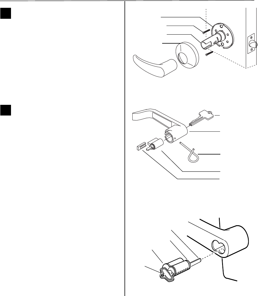
Installation Instructions for Stanley Omnilock 9KOM Cylindrical Locks
Stanley Omnilock
a Product Group of Stanley Security Solutions, Inc.
10
Installing the lock
3 Insert the control key into the core and rotate the
key 15 degrees to the right.
4 Insert the throw member into the core.
5 Insert the core and throw member into the lever
with the control key
6 Return the control key to the original position
and withdraw the key.
Caution: The control key can be used to
remove cores and to access doors. Provide
adequate security for the control key.
10 Test lock
To test the lock for proper operation before the lock
is programmed:
For keypad locks
1 Press 1234 for the 2000 series, or 5011234
for the 500 series.
The green light flashes and the latch unlocks.
2 Turn the lever and open the door.
During the unlock time, the green light flashes. Then
the red light flashes and the latch relocks.
For magnetic stripe or proximity card only locks
Note: If the lock has a proximity card reader, it may
have already been activated by the presence of an
object near the card reader.
1 Align the magnetic stripe card with the V mark by
the card slot.
2 Insert and then remove the card.
The green light flashes and the latch unlocks.
3 Turn the lever and open the door.
During the unlock time, if using the Programming
Default ID Card, the green light flashes. Then the red
light flashes and the latch relocks.
Troubleshooting
If the mechanism does not unlock, remove the bat-
tery cover and check for proper orientation and seat-
ing of the batteries and motor connector. Ensure that
wires are not pinched. Reset the electronics by press-
ing and holding the reset button on the circuit board
until the light flashes green (approx three seconds),
then release. See Figure 12.
The system will go through a self-test and the green
light will flash five times. You will hear the lock
unlock, then relock three times. A red flash indicates
a PC board or drive system problem. If a red flash or
no flash is observed, check for proper orientation
and seating of the batteries and motor connector,
ensure that wires are not pinched, then repeat the
reset process.
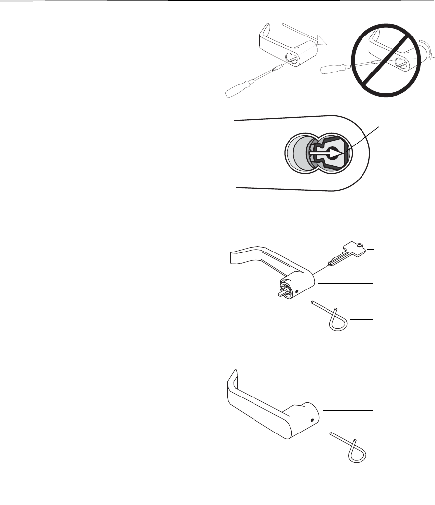
Installation Instructions for Stanley Omnilock 9KOM Cylindrical Locks
Stanley Omnilock
a Product Group of Stanley Security Solutions, Inc.
11
Installation Instructions for Stanley Omnilock 9KOM Cylindrical Locks
Installing the lock
Removing the levers (when needed)
Removing the IC outside lever
1 Insert the control key into the core and rotate the
key 15 degrees to the right.
2 Remove the core and throw member from the
lever.
3 Insert a flat blade screwdriver into the figure-8
core hole and against the trapezoid-shaped lever
keeper.
4 Push the screwdriver blade in the direction of the
arrow in Figure 18.
Caution: Use the flat of the screwdriver to
push the lever keeper sideways. Using the
screwdriver tip to pry the keeper at an angle
may result in unseating the retaining spring.
For assistance, contact your local Stanley
Omnilock dealer.
M
Note: You will not be able to remove the lever if the
screwdriver blade is inserted past the keeper into
the center hole.
5 Slide the lever from the sleeve.
Removing the non-IC outside lever
1 Insert the key into the cylinder and turn it 45
degrees clockwise.
2 Depress the lever catch through the hole in the
outside lever by using the push pin or other
suitable tool. See Figure 19.
3 Slide the outside lever off.
Removing the inside lever
1 Depress the lever catch through the hole in the
inside lever by using the push pin or other
suitable tool as shown in Figure 20.
2 Slide the inside lever off.
Note: Reinstall lever(s) according to “Install
through-bolts, inside rose and lever” on page 9, or
“Install outside lever, core and throw member” on
page 9
Figure 18 Push the lever keeper to remove the lever
Lever keeper
Figure 19 Removing the outside non-IC lever
Push pin
Outside lever
Turn key 45
degrees
clockwise
Figure 20 Removing the inside lever
Push pin
Inside lever
Stanley Omnilock
a Product Group of Stanley Security Solutions, Inc.
12

Stanley Omnilock
a Product Group of Stanley Security Solutions, Inc.
1
Planning the installation
T83312/Rev B 3132456 ER-7991-12 Feb 2011
Contents
These installation instructions describe how to install
your 45HOM Mortise Lock. Topics covered include:
Planning the installation...........................................1
Preparing the door and door jamb..........................4
Installing the lock........................................................7
Completing the installation......................................9
Site survey
Use the following survey to record information
about the installation site. You need this information
to determine how to prepare the door for the lock.
Door information
Door handing and bevel:
If a handing change is required, see “Rotate latchbolt
(if necessary)” on page 4.
❐ Left hand (LH)
❐ Left hand, reverse bevel (LHRB)
❐ Right hand (RH)
❐ Right hand, reverse bevel (RHRB)
Door thickness: 1-3/4 to 2 inches (44 to 50 mm).
Environment information
a. See Stanley installation instruction Addendum (T83317)
Extreme Weatherized Installation for the extreme weatherized
model installation.
Model Side of
door
Temperature
Range Exposure
Standard Outside +32°F to +129°F
0°C to +54°C
Drip proof.
Inadvertent
splashing of
water spray
acceptable.
Weatherized Outside -4°F to +129°F
-20°C to +54°C
Direct exposure
to rain and snow
Extreme
Weatherized a
Outside -40°F to +129°F
-40°C to + 54°C
Direct exposure
to rain and snow
Inside +32°F to +129°F
0°C to +54°C N/A
Installation Instructions for
Stanley Omnilock 45HOM
Mortise Locks
Components checklist
Use the following checklist to make sure that you
have the items necessary to install your Omnilock
Mortise Lock.
Components provided in the box:
❐ Inside and outside trim cassettes
❐ Inside and outside rose and rose ring
❐ Outside escutcheon assembly
❐ Mortise case assembly
❐ Mortise cylinder and collar
❐ Outside lever and spindle assembly
❐ Inside lever
❐ Strike package
❐ Installation template and instructions
❐ Screw package
❐ Mortise case faceplate
❐ Batteries
❐ Torx T15 driver
❐ 1/8” hex wrench
Other components:
❐ Programming Default ID Card (provided with
software)
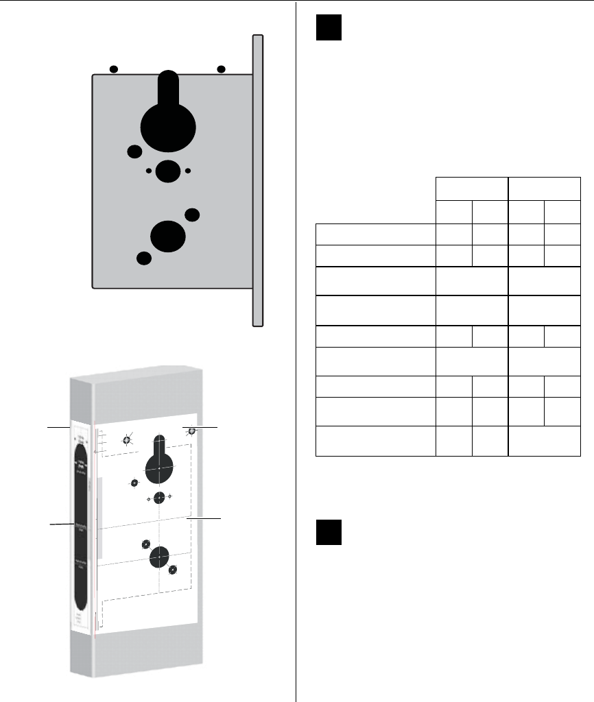
Installation Instructions for Stanley Omnilock 45HOM Mortise Locks
Stanley Omnilock
a Product Group of Stanley Security Solutions, Inc.
2
Planning the installation
1Identify holes to drill
1 Determine the lock function to be installed.
2 Determine the inside and outside, hand, and
bevel of the door.
3 See the Holes by Function table and Figure 3 to
determine the holes to be drilled for the lock
function.
2Position template and mark drill
points
Note: If the door is a fabricated hollow metal door,
determine whether it is properly reinforced to
support the lock. If door reinforcement is not
adequate, consult the door manufacturer for
information on proper reinforcement. For
dimensions for preparing metal doors, see the OM2
Template — Installation Specifications for
45HOM Mortise Locks (T83318).
Functions
Holes by Function DV TV
Door side In Out In Out
ACylinder ■■
BThumb turn ■
CLever aThrough
door
Through
door
DTrim mounting
(2 holes) a
a. Because these holes pass through the mortise pocket, it is
recommended that each hole be drilled separately rather
than straight through.
Through
door
Through
door
EGrounding hole ■■
FThrough bolt hole Through
door
Through
door
GStandoff hole ■■
HThumb turn mounting
screw (2 holes) ■
J Door Status Switch
(Optional)
Door
Edge
A
B
C
D
E
F
HH
FGG
D
For hole sizes, see
the OM1 Template
T83316
Figure 1 Identifying holes to drill
Horizontal center line
of lock
3/8 in
10 m
m
7/8
in
23
m
m
HB
1/2 in
13 mm
Horizontal center line
of lever
Align to edge of door
r.
Note:Us e this template for the
insideof a LH or LHRB door
or the outside (keyed side) of
a RH or RHRB door.
Detach here
Strike lip
Lowedge
(narrowside)
Flat edge –
no bevel
Highedge
(wide side)
A
E
FF
D
D
5/16 in
8 mm
1/8 in
3 mm
3/16 in
5 mm
3/16 in
5 mm
Hole Descriptions
A Cyinder (1)
B Thumb turn (1)
C Lever (1)
D Trim mounting (2)
E Grounding(1)
F Module bolt(2)
G Module sta ndoff(2)
H Thumb turn
mountingscrew(2)
G
5/16 in
8 mm
3/8 in
10 mm
A
G
5/16 in
8 mm
C
1 1/4 in
32 mm
Verticalcenter line
of lever
Toensureaccuratedoorpreparation,useonlyfactory-
printedtemplates.Do notusecopiesorfacsimilies.
Figure 2 Aligning the templates
Installation
template
Door edge
template
Centerline
Centerline
Installation Instructions for Stanley Omnilock 45HOM Mortise Locks
Stanley Omnilock
a Product Group of Stanley Security Solutions, Inc.
3
Installation Instructions for Stanley Omnilock 45HOM Mortise Locks
Planning the installation
1 Separate the templates provided on the OM1
Template — Installation Template for 45H Mortise
Locks (T83316).
Note: If installing an Extreme Weatherized model,
see Installation Addendum for Stanley Omnilock
45HOM Extreme Weatherized Locks (T83317). This
includes the template for locating the extreme
weatherized module mounting holes.
2 Position one of the door edge templates on the
door, making sure that the lock case mortise
shown on the template aligns with the mortise
pocket prepared in the door.
3 Using the centerlines on the door edge templates
as guides, position the appropriate door template
on each side of the door. You need to take the
bevel into account. Tape the templates to the
door.
3Center punch and drill holes
1 Center punch the necessary drill points. See the
instructions on the template.
2 Drill the holes.
Note 1: To locate the center of a hole on the
opposite side of the door, drill a pilot hole
completely through the door.
Note 2: For holes through the door, it is best to drill
halfway from each side of the door to prevent the
door from splintering.
4Optional: Install door status switch
(Optional for TV function wireless
locks only)
1 Locate the centerpoint for the door status switch
2 1/2” (64mm) above the top of the faceplate
mortise on the edge of the door as shown in
Figure 4.
2 Drill a 1” (25 mm) diameter hole 1 3/4” (44 mm)
deep for the door status switch.
3 Position the drill so the tip of the bit is
approximately 1”(25 mm) into the hole and the
Outside
Outside
Left hand (LH) Right hand (RH)
Left hand
reverse bevel
(LHRB)
Right hand
reverse bevel
(RHRB)
Figure 3 Door Handing Chart
Figure 4 Installing the door status switch
Door status
switch
Optional for Wireless TV Models
Door status
switch sensor
Centerline
Door
Door Jamb
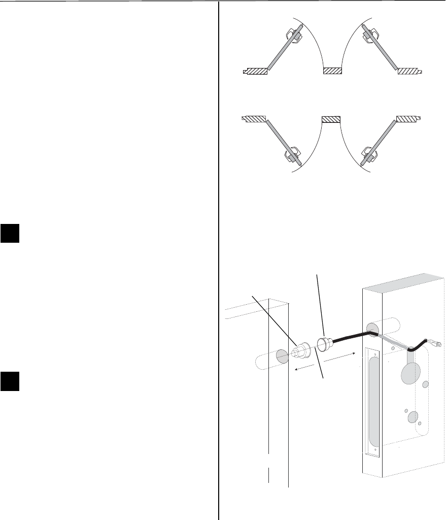
Installation Instructions for Stanley Omnilock 45HOM Mortise Locks
Stanley Omnilock
a Product Group of Stanley Security Solutions, Inc.
3
Installation Instructions for Stanley Omnilock 45HOM Mortise Locks
Planning the installation
1 Separate the templates provided on the OM1
Template — Installation Template for 45H Mortise
Locks (T83316).
Note: If installing an Extreme Weatherized model,
see Installation Addendum for Stanley Omnilock
45HOM Extreme Weatherized Locks (T83317). This
includes the template for locating the extreme
weatherized module mounting holes.
2 Position one of the door edge templates on the
door, making sure that the lock case mortise
shown on the template aligns with the mortise
pocket prepared in the door.
3 Using the centerlines on the door edge templates
as guides, position the appropriate door template
on each side of the door. You need to take the
bevel into account. Tape the templates to the
door.
3Center punch and drill holes
1 Center punch the necessary drill points. See the
instructions on the template.
2 Drill the holes.
Note 1: To locate the center of a hole on the
opposite side of the door, drill a pilot hole
completely through the door.
Note 2: For holes through the door, it is best to drill
halfway from each side of the door to prevent the
door from splintering.
4Optional: Install door status switch
(Optional for TV function wireless
locks only)
1 Locate the centerpoint for the door status switch
2 1/2” (64mm) above the top of the faceplate
mortise on the edge of the door as shown in
Figure 4.
2 Drill a 1” (25 mm) diameter hole 1 3/4” (44 mm)
deep for the door status switch.
3 Position the drill so the tip of the bit is
approximately 1”(25 mm) into the hole and the
Outside
Outside
Left hand (LH) Right hand (RH)
Left hand
reverse bevel
(LHRB)
Right hand
reverse bevel
(RHRB)
Figure 3 Door Handing Chart
Figure 4 Installing the door status switch
Door status
switch
Optional for Wireless TV Models
Door status
switch sensor
Centerline
Door
Door Jamb
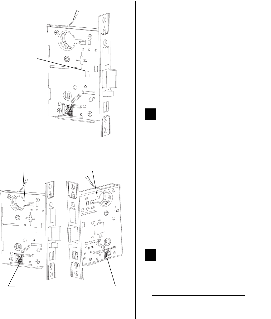
Installation Instructions for Stanley Omnilock 45HOM Mortise Locks
Stanley Omnilock
a Product Group of Stanley Security Solutions, Inc.
4
Configuring & installing the mortise
bit is close to the top edge of the hole. Then drill a
3/8” (10mm) channel at approximately a 35°
angle from the door status switch hole into the
mortise cavity as shown in Figure 4.
Caution: Make sure the wires are not routed
across any sharp edges or over any surface
that could damage the sleeving.
4 Press fit the door status switch assembly into the
door status switch hole.
5 On the door jamb, drill a corresponding hole for
the door status switch sensor. Use the door switch
centerline as a guide. Press fit the sensor into the
jamb.
5Rotate latchbolt (if necessary)
Note: If a function specific mortise case was
ordered, some steps for configuring the case have
already been performed at the factory.
1 Determine whether you need to rotate the
latchbolt to match the handing of the door.
Note: The angled surface of the latchbolt must
contact the strike when the door closes.
2 If you need to rotate the latchbolt, insert a flat
blade screwdriver into the latch access point
approximately 1/2” (13 mm) into the case and
press to extend the latch out of the case. See
Figure 5.
3 Rotate the latchbolt past 180 degrees, keeping
constant pressure on the latch access point. Then
allow the latch to rotate back slightly and retract
into the case.
6Position hub toggles (if necessary)
1 Check whether the hub toggles are in the proper
position for the lock. See the table below.
Hub toggle positions
Inside down (always unlocked)
Outside up (lockable)
Figure 5 Rotating the latchbolt
Latch access point
Hub toggle Hub toggle
Figure 6 Positioning hub toggles
Cover side Case (back) side
Installation Instructions for Stanley Omnilock 45HOM Mortise Locks
Stanley Omnilock
a Product Group of Stanley Security Solutions, Inc.
5
Installation Instructions for Stanley Omnilock 45HOM Mortise Locks
Installing the trim
2 For LH & LHRB doors, the inside is the case (back)
side of the case and the outside is the cover side
of the case. For RH and RHRB doors, the inside is
the cover side of the case and the outside is the
case (back) side of the case. The cover is mounted
to the case with four screws.
3 To change the position of a hub toggle, loosen
the toggle screw, move the toggle into the
desired position, and re-tighten the screw.
7Install mortise case
1 Drill the holes for the case mounting screws.
2 Insert the mortise case into the mortise cavity,
while feeding the motor wires and any optional
sensor wires into the mortise cavity and keyhole
to the inside of the door as shown in Figure 7.
Note: The armored front of the mortise case self-
adjusts to the door bevel.
3 Secure the mortise case with the case mounting
screws.
8Install trim mounting plates
1 Insert the outside trim mounting plate through
the door and mortise case.
Option DV TV Stand
Alone Wireless
Key Overide Sensor
(KOS) ■ ■ ■� ■
Request-to-Exit
(RQE) ■ ■� ■
Door Status Switch
(DS) a
a. Door status switch is located differently for DV and TV
functions.
■ ■� ■
Latch Status
Switch (LS) ■■
Mortise case
Case
mounting
screws
Figure 7 Installing the mortise case
Door Status Switch
(TV location shown)
Motor wire
DS (white)
RQE (org/brown)
LS/LSM (purple)
KOS (gray)
(red/black)
Figure 8 Installing the trim mounting plates
Outside trim
Inside trim
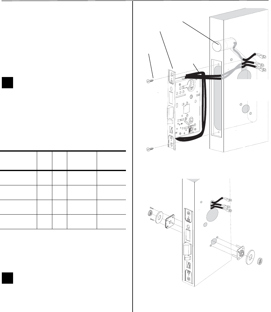
Installation Instructions for Stanley Omnilock 45HOM Mortise Locks
Stanley Omnilock
a Product Group of Stanley Security Solutions, Inc.
5
Installation Instructions for Stanley Omnilock 45HOM Mortise Locks
Installing the trim
2 For LH & LHRB doors, the inside is the case (back)
side of the case and the outside is the cover side
of the case. For RH and RHRB doors, the inside is
the cover side of the case and the outside is the
case (back) side of the case. The cover is mounted
to the case with four screws.
3 To change the position of a hub toggle, loosen
the toggle screw, move the toggle into the
desired position, and re-tighten the screw.
7Install mortise case
1 Drill the holes for the case mounting screws.
2 Insert the mortise case into the mortise cavity,
while feeding the motor wires and any optional
sensor wires into the mortise cavity and keyhole
to the inside of the door as shown in Figure 7.
Note: The armored front of the mortise case self-
adjusts to the door bevel.
3 Secure the mortise case with the case mounting
screws.
8Install trim mounting plates
1 Insert the outside trim mounting plate through
the door and mortise case.
Option DV TV Stand
Alone Wireless
Key Overide Sensor
(KOS) ■ ■ ■� ■
Request-to-Exit
(RQE) ■ ■� ■
Door Status Switch
(DS) a
a. Door status switch is located differently for DV and TV
functions.
■ ■� ■
Latch Status
Switch (LS) ■■
Mortise case
Case
mounting
screws
Figure 7 Installing the mortise case
Door Status Switch
(TV location shown)
Motor wire
DS (white)
RQE (org/brown)
LS/LSM (purple)
KOS (gray)
(red/black)
Figure 8 Installing the trim mounting plates
Outside trim
Inside trim
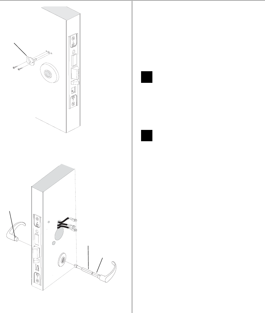
Installation Instructions for Stanley Omnilock 45HOM Mortise Locks
Stanley Omnilock
a Product Group of Stanley Security Solutions, Inc.
6
Installing the lock
2 Position the inside trim mounting plate opposite
the outside trim mounting plate and screw them
securely in place.
Caution: Do not overtighten the trim
mounting plate screws. Overtightening may
damage the locking mechanism.
3 Temporarily install a lever and test the lock to
make sure that it doesn’t bind.
9Install thumb turn (TV function only)
1 Orient the thumb turn so it points up when the
deadbolt is retracted, and toward the hinge edge
of the door when the deadbolt is extended.
2 Install the thumb turn using the two screws
provided. See Figure 9.
10 Install inside and outside levers
1 Unscrew the inside spindle one full turn to allow
the spindles to turn freely. See Figure 10.
2 Remove the label from the inside spindle.
3 With the handle pointing toward the door hinges,
insert the outside lever and spindle assembly into
the lock from the outside of the door.
4 Slide the inside lever onto the inside spindle and
secure it with the set screw.
5 Turn the levers to check that they operate
smoothly.
Figure 9 Installing the thumb turn
Thumb turn
Inside door
Figure 10 Installing the levers
Location
of set screw
Spindle Assembly
on Outside door
Inside spindle
Outside spindle
Installation Instructions for Stanley Omnilock 45HOM Mortise Locks
Stanley Omnilock
a Product Group of Stanley Security Solutions, Inc.
7
Installation Instructions for Stanley Omnilock 45HOM Mortise Locks
Installing the lock
11 Install batteries
Four alkaline AA batteries (or two weatherized packs
if installing a weatherized unit) are furnished with
your Omnilock system and must be installed before
proceeding with operation verification and system
installation.
Note: For the Extreme Weatherized model, see
Addendum (T83317) Extreme Weatherized
Installation for battery and escrutcheon
installation.
1 Remove the gasket from the rear of the housing
assembly as shown in Figure 11.
2 Remove the screw from the battery cover and
remove the cover.
3 Install batteries with proper polarity as shown in
Figure 12. (For weatherized battery packs, simply
connect the wires from the battery pack to the
circuit board as shown in Figure 13.)
Note: Be sure red and black motor wires are
connected before attempting step 4. Align the wires
together so that the wire colors match.
4 Press and hold the reset button on the PC board
(as shown in Figure 12) until the green light on
the keypad flashes (about three seconds) then
release the button. If green light does not flash,
see “Troubleshooting” on page 12.
5 Replace the battery cover. See Figure 11. Make
sure that the tabs on the lower edge of the
battery cover are hooked over the edge of the
back plate and secure the cover with the screw.
6 Replace the gasket. See Figure 11. Make sure that
it is inside the edge of the housing.
Figure 11 Installing batteries
Housing assembly
AA Batteries
Back plate
Battery cover
Gasket
Track setting
label
Screw
Figure 12 Using the reset button
Reset button
Figure 13 Installing weatherized batteries
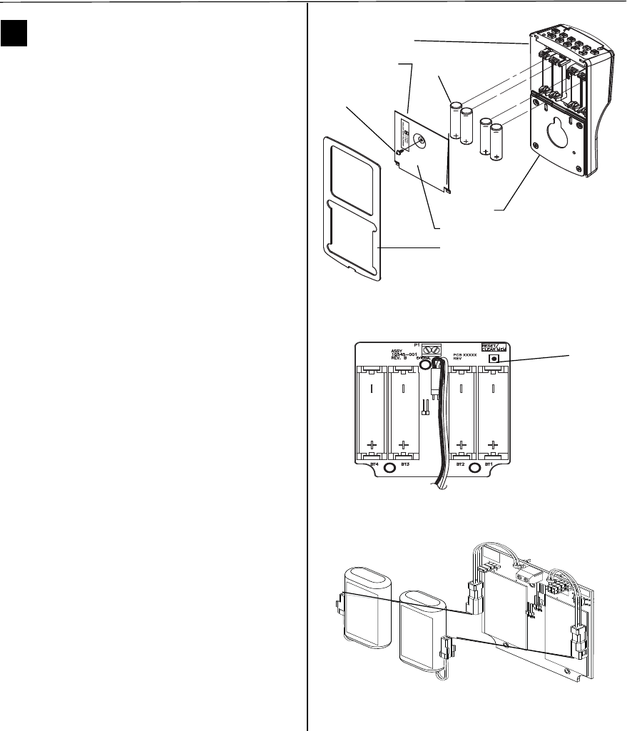
Installation Instructions for Stanley Omnilock 45HOM Mortise Locks
Stanley Omnilock
a Product Group of Stanley Security Solutions, Inc.
7
Installation Instructions for Stanley Omnilock 45HOM Mortise Locks
Installing the lock
11 Install batteries
Four alkaline AA batteries (or two weatherized packs
if installing a weatherized unit) are furnished with
your Omnilock system and must be installed before
proceeding with operation verification and system
installation.
Note: For the Extreme Weatherized model, see
Addendum (T83317) Extreme Weatherized
Installation for battery and escrutcheon
installation.
1 Remove the gasket from the rear of the housing
assembly as shown in Figure 11.
2 Remove the screw from the battery cover and
remove the cover.
3 Install batteries with proper polarity as shown in
Figure 12. (For weatherized battery packs, simply
connect the wires from the battery pack to the
circuit board as shown in Figure 13.)
Note: Be sure red and black motor wires are
connected before attempting step 4. Align the wires
together so that the wire colors match.
4 Press and hold the reset button on the PC board
(as shown in Figure 12) until the green light on
the keypad flashes (about three seconds) then
release the button. If green light does not flash,
see “Troubleshooting” on page 12.
5 Replace the battery cover. See Figure 11. Make
sure that the tabs on the lower edge of the
battery cover are hooked over the edge of the
back plate and secure the cover with the screw.
6 Replace the gasket. See Figure 11. Make sure that
it is inside the edge of the housing.
Figure 11 Installing batteries
Housing assembly
AA Batteries
Back plate
Battery cover
Gasket
Track setting
label
Screw
Figure 12 Using the reset button
Reset button
Figure 13 Installing weatherized batteries
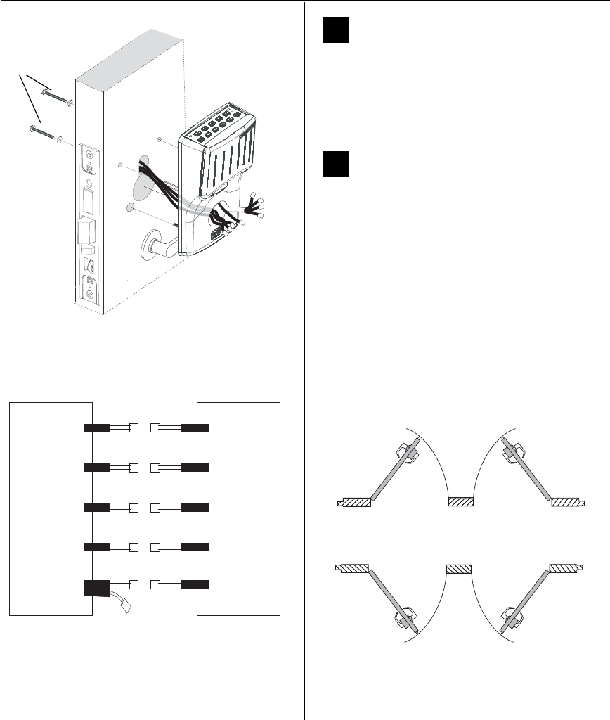
Installation Instructions for Stanley Omnilock 45HOM Mortise Locks
Stanley Omnilock
a Product Group of Stanley Security Solutions, Inc.
8
Installing the lock
12 Install outside escutcheon
1 Ensure that no wires are pinched when attaching
the escutcheon to the door.
2 Insert the standoffs and grounding spring into the
predrilled holes. Use screws and washers to attach
the escutcheon from the inside of the door.
13 Connecting escutcheon wires
1 Connect the red and black motor wire from the
mortise case to the red and black escutcheon
motor wire. Align the wires together so that the
wire colors match.
2 Connect the color-coded wires of the escutcheon
wiring harness to the corresponding wire options
on your mortise case. Some wires may not be
used.
Note: Two RQE status switches are installed in the
mortise case. However, only the switch for the inside
of the lock needs to be connected. You will need to
connect the ‘Case Side’ pair of RQE wires for LH and
LHRB doors or the ‘Cover Side’ pair of RQE wires for
RH and RHRB doors. See Figure 16. Wires are
labeled.
Figure 14 Installing the outside escutcheon
Screws and
washers
Mortise Escutcheon
Motor
Key Override
Sensor
Request to
Exit
Door Status
Switch
Latch Status
Switch
Motor
Key Override
Sensor
Request to
Exit
Door Status
Switch
Latch Status
Switch
Red/black Red/black
Gray Gray or Yellow
White White
Purple Purple
Orange/Brown Orange
Figure 15 Simplified wiring diagram
Outside
Outside
Left hand (LH) Right hand (RH)
Left hand
reverse bevel
(LHRB)
Right hand
reverse bevel
(RHRB)
Figure 16 Door Handing Chart
Installation Instructions for Stanley Omnilock 45HOM Mortise Locks
Stanley Omnilock
a Product Group of Stanley Security Solutions, Inc.
9
Installation Instructions for Stanley Omnilock 45HOM Mortise Locks
Finishing the installation
14 Install cylinder
1 Push any excess wires into the escutcheon
housing. Make sure no wires are pinched.
1 Make sure cylinder collar is positioned on the
cylinder.
2 Thread the cylinder into the mortise case. Rotate
the cylinder until the cylinder is flush against the
collar and the cylinder cam is in the 12 o’clock
position. See Figure 17.
Caution: A malfunction can occur if the
cylinder is threaded in too far.
3 Secure the cylinder in the mortise case with the
cylinder retainer screw.
15 Install mortise case faceplate
1 Secure the mortise case faceplate to the mortise
case with the faceplate mounting screws. See
Figure 18.
2 Check the lock for proper operation.
Figure 17 Installing the standard cylinder
Cylinder
Cylinder
retainer
screw
Cylinder collar
Figure 18 Installing the mortise case faceplate
TV Faceplate
DV Faceplate
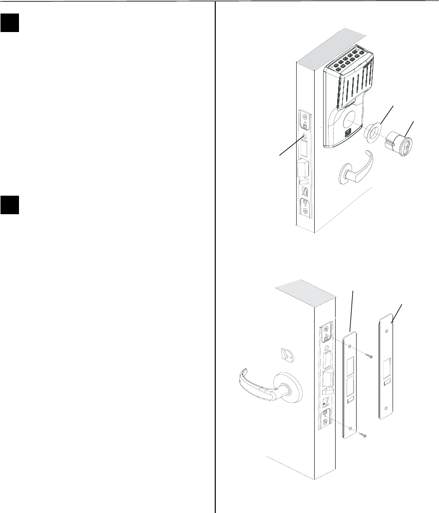
Installation Instructions for Stanley Omnilock 45HOM Mortise Locks
Stanley Omnilock
a Product Group of Stanley Security Solutions, Inc.
9
Installation Instructions for Stanley Omnilock 45HOM Mortise Locks
Finishing the installation
14 Install cylinder
1 Push any excess wires into the escutcheon
housing. Make sure no wires are pinched.
1 Make sure cylinder collar is positioned on the
cylinder.
2 Thread the cylinder into the mortise case. Rotate
the cylinder until the cylinder is flush against the
collar and the cylinder cam is in the 12 o’clock
position. See Figure 17.
Caution: A malfunction can occur if the
cylinder is threaded in too far.
3 Secure the cylinder in the mortise case with the
cylinder retainer screw.
15 Install mortise case faceplate
1 Secure the mortise case faceplate to the mortise
case with the faceplate mounting screws. See
Figure 18.
2 Check the lock for proper operation.
Figure 17 Installing the standard cylinder
Cylinder
Cylinder
retainer
screw
Cylinder collar
Figure 18 Installing the mortise case faceplate
TV Faceplate
DV Faceplate
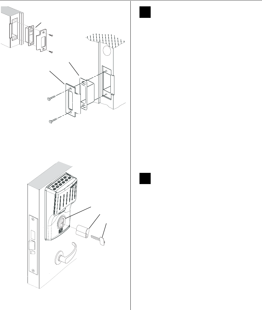
Installation Instructions for Stanley Omnilock 45HOM Mortise Locks
Stanley Omnilock
a Product Group of Stanley Security Solutions, Inc.
10
Finishing the installation
16 Install strike box and strike plate
1 If the door jamb has not been mortised for the strike
box and strike plate, perform these steps:
a On the door jamb, locate the horizontal
centerline of the strike (3/8” (10mm) above the
centerline of the lock), as well as the vertical
centerline of the strike.
b Mortise the door jamb to fit the strike box and
strike plate.
c Drill the holes for the screws used to install the
strike box and strike plate.
2 Insert the strike box into the mortise in the door
jamb. Place the strike plate over the strike box
and secure the strike with the screws provided.
Note: If installing a DV wireless model with a Door
Status Switch, ensure that the magnet is located at
thetop of the strike box. See Figure 19.
3 Check the position of the auxiliary bolt against the
strike plate (or the filled area of the strike box).
Note: The recommended gap between the door
and jamb is 1/8” (3 mm).
17 Install core
1 Insert the control key into the core and rotate the
key 15 degrees (midway between the 12 o'clock
and 1 o'clock positions) to the right.
2 With the control key in the core, insert the core
into the cylinder.
3 Return the control key to the 12 o’clock position
and withdraw the key.
Caution: The control key can be used to
remove cores and to access doors. Provide
adequate security for the control key.
Figure 19 Installing the strike box and strike plate
Strike box
Strike plate
Strike box with DSS magnet
Figure 20 Installing the core
Control key
Core
Cylinder

Installation Instructions for Stanley Omnilock 45HOM Mortise Locks
Stanley Omnilock
a Product Group of Stanley Security Solutions, Inc.
11
Installation Instructions for Stanley Omnilock 45HOM Mortise Locks
Finishing the installation
18 Check operation
Check the operation of the lock. For example, check
that:
❐ door latches and opens properly
❐ deadbolt operates properly
❐ key access works
❐ door gap is 1/8” (3 mm)
❐ auxiliary bolt is held inside the case when the door
is closed.
For assistance, contact your local Stanley Omnilock
dealer.
19 Test lock
To test the lock for proper operation before the lock
is programmed, follow these instructions:
For keypad locks
1 Press 1234 for the 2000 series, or 5011234
for the 500 series.
The green light flashes and the latch unlock.
2 Turn the lever and open the door.
During the unlock time, the green light flashes. Then
the red light flashes and the latch relocks.
For magnetic stripe or proximity card locks only
Note: If the lock has a proximity card reader, it may
have already been activated by the presence of an
object near the card reader.
1 Align the magnetic stripe card with the V mark by
the card slot.
2 Insert and then remove the card.
The green light flashes and the latch unlocks.
3 Turn the lever and open the door.
During the unlock time, if using the Programming
Default ID Card, the green light flashes. Then the red
light flashes and the latch relocks.
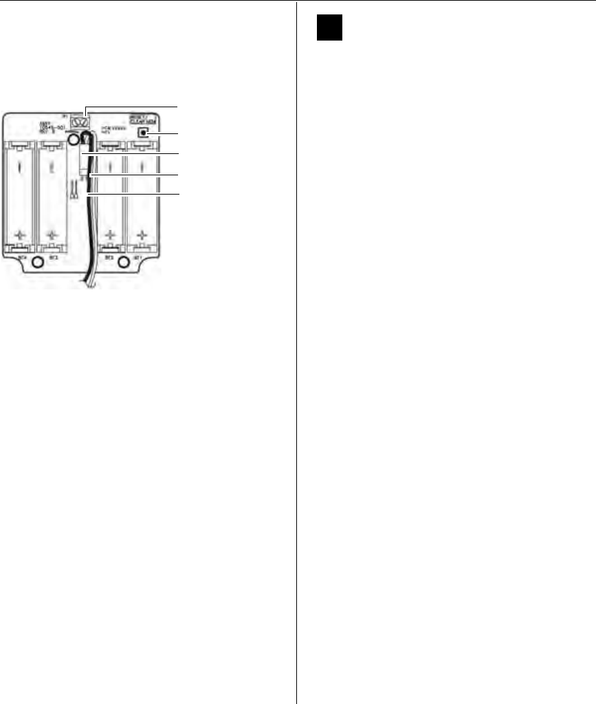
Installation Instructions for Stanley Omnilock 45HOM Mortise Locks
Stanley Omnilock
a Product Group of Stanley Security Solutions, Inc.
12
Finishing the installation
20 Troubleshooting
If the mechanism doesn’t unlock, remove the battery
cover and check for proper orientation and seating of
the batteries and motor connector. Ensure that wires
are not pinched. Reset the electronics by pressing
and holding the reset button on the circuit board
until the light flashes green (approximately three
seconds), then releasing the botton. See Figure 21.
Note: The system will go through a self-test and the
green light will flash five times. You will hear the
lock unlock, then relock three times. A red flash
indicates a PC board or drive system problem. If a
red flash or no flash is observed, check for proper
orientation and seating of the batteries and motor
connector, ensure that wires are not pinched, then
repeat the reset process.
Check operation
1 Press 1234 for the 2000 series, or 5011234
for the 500 series.
During the unlock time, the green light flashes; then
the red light flashes and the latch relocks.
2 Turn the lever and open the door.
3 If your system has a magnetic card reader, verify
proper operation of the system using the
magnetic card reader; otherwise, see “Test lock”
on page 11.
A label on the housing assembly battery cover indi-
cates the magnetic card track (track 2 or track 3) that
the system is set to read. See Figure 11.
Figure 21 Using the reset button
Reset button
Motor connector
Red wire
Black wire
Terminal block