dormakaba USA SDC2K Wireless Electronic Lock User Manual Manual 2
Stanley Security Solutions, Inc. Wireless Electronic Lock Manual 2
Contents
Manual 2
101
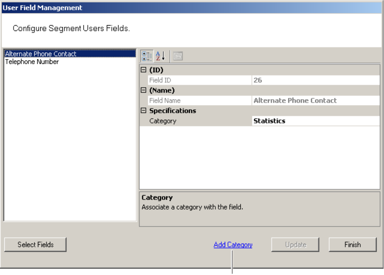
Adding a New User Fields Category
1 In the User Field Management of Segment dialog box, click the Add Category
Link at the bottom of the dialog box.
Figure 71 Add Category
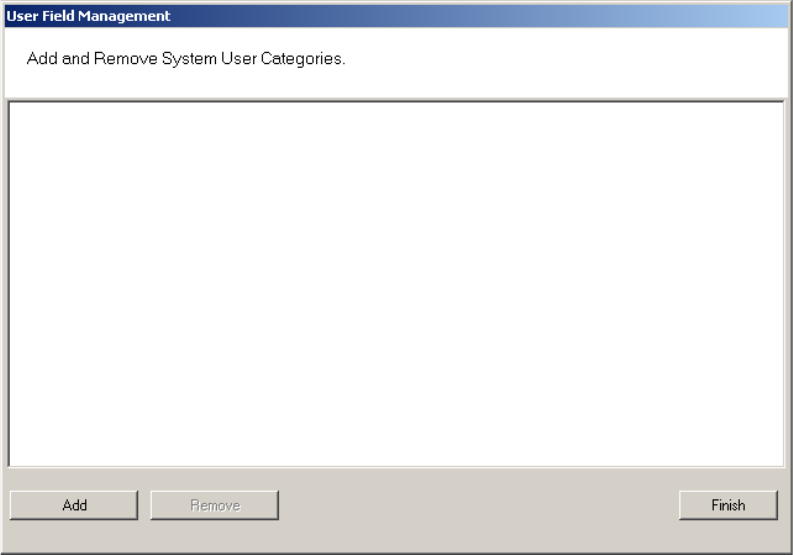
2 The Add and Remove System User Categories window opens.
Add Category
102
Figure 72 Adding and Remove System User Categories
3 Click the Add button. “Category 1” appears in the text box.
4 Double-click on “Category 1” to rename it.
5 Click Finish. In the Configure Segment Users Fields dialog box, the new cat-
egory is now available for selection from the Category drop-down list. Now you
can select this category when defining a new User Field.
103
Removing User Fields and Categories
You can also remove added User Fields and Categories from the system. The sys-
tem will not allow you to do this, however, if the field or category is in use. Before
you remove the field or category, ensure there are no records assigned to them,
then perform the following steps.
To remove User Fields from the system
1 In the User Fields Management dialog box, click the Select Fields button at the
bottom of the dialog box.
2 From the User Fields in Facility list on the left, select the fields you wish to re-
move and click Remove>>. The field is moved to the User Fields list on the right,
and remains inactive unless you add it back to the list.
3 Click Finish. The field is no longer available in the User Fields list.
To remove added Categories from the system
1 In the User Field Management window, select Add Category.
2 The Add and Remove System User Category window opens.
3 Select the category you wish to remove, and click Remove. Click Finish when
you are done.
User Groups
User Groups are a convenient way to define properties that will affect certain
groups of individuals in your system. For example, if your Administrative personnel
have different hours or entry parameters, you can create an Administrative group,
make that group a Timezone Group and assign administrative personnel to that
group.
You can define any number of User Groups, such as Administrative, General, Labo-
ratories, Dormitories, Night Shift, Contractors, and so on.
Adding User Groups
1 In the Users Tab, Associations category, click the User Groups field. Select
the ellipsis button at the far right of the field. The User Group Setup dialog box
opens.
104
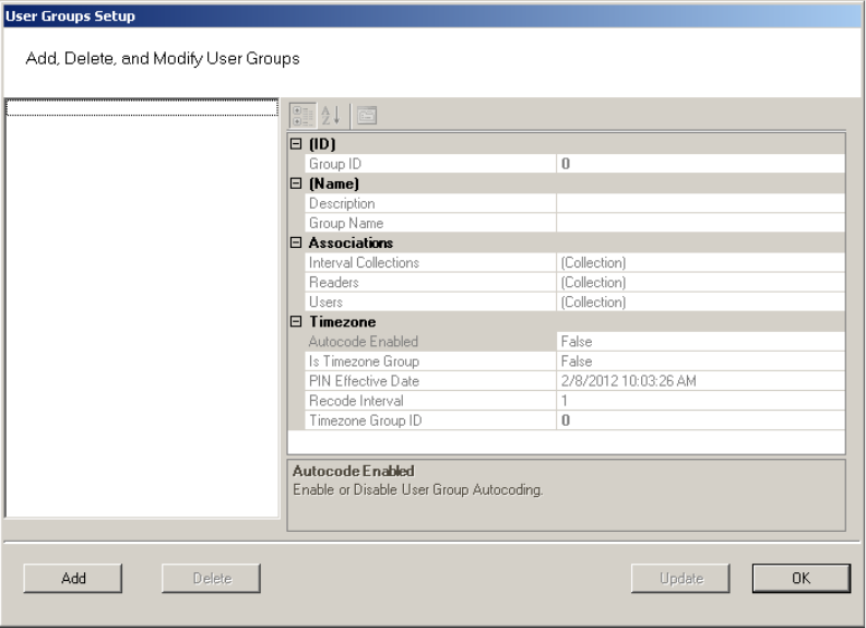
Figure 73 User Groups Setup
2 The groups you create display on the left. The group’s ID, Name, Associations
and Timezone appear on the right.
3 Select Add. A new Group (Group1) is created and displays on the left.
4 In the Group Name box, replace the name Group1 with a name for the new
group (for example, Administrative).
5 Select OK.
Note Once you have added users to the system via the Users Tab, you can assign them
to these User Groups.
Removing User Groups
In the User Group Setup dialog box, select the group you wish to remove and se-
lect the Delete button. The group is immediately removed from the list, along with
its associations.
Associating Users with User Groups
1 In the Segment Tab, Associations category, click the User Groups field.
2 Select the ellipsis button at the far right of the field.
3 In the User Groups Setup dialog box, select the group you wish to associate
105
with users.
4 In the Associations category, click in the Users field and select the ellipsis but-
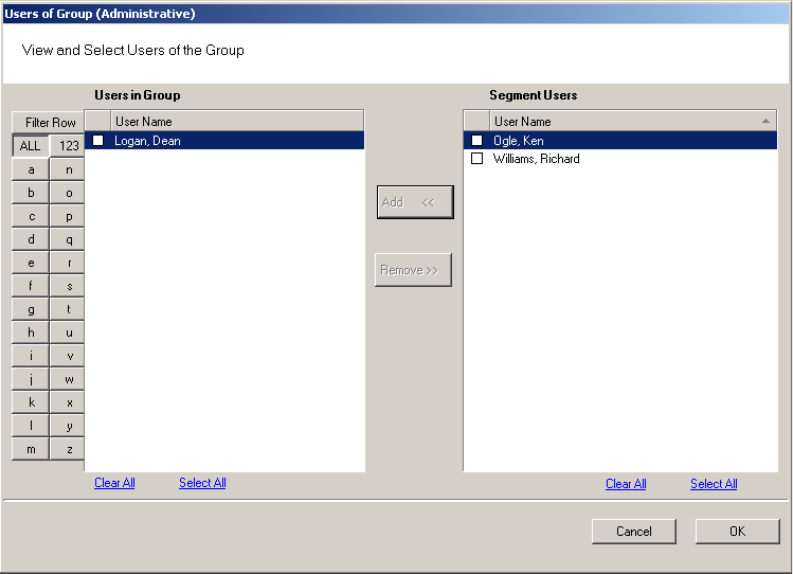
ton. The Users of Group dialog box opens.
5 All users in the segment not already assigned to the group are displayed under
Segment Users list on the right.
Figure 74 Users of Group
Note Users will not appear in the Segment Users list until they have been added to the
system. If you have a large number of users, you can use the Alphabetic sorter
buttons on the left of the list to more quickly find a specific user.
6 Select the checkbox next to the users you wish to associate with the User
Group.
7 Select <<Add. The User names will be removed from the Segment Users list on
the right and display under Users in Group list on the left.
8 Select OK to close the Users of Group dialog box.
106
Removing Users from User Group
1 In the User Groups Setup dialog box, select the group in which the user cur-
rently resides.
2 In the Associations category, click on the Users field, and select the ellipsis
button. The Users of Group dialog box opens.
3 From the Users in Group list on the left, select the checkbox next to the user
you wish to remove from the group.
4 Select Remove. The user name will be removed from Users in Group list on the
left and moved back to the Segment Users list on the right. Select OK to close
the Users of Group dialog box.
Timezone User Groups
You can create up to 512 Timezone User Groups to further define access levels for
the Master Timezone. These can restrict access of a certain group of employees
to a specific time period. Perform the following steps to create a timezone user
group.
1 In the Segment Tab, select the Segment to which you wish to add a new Time-
zone User Group.
2 In the Associations Category, select User Groups and click the ellipsis button at
the far right of the field. The User Groups Setup dialog box opens.
107
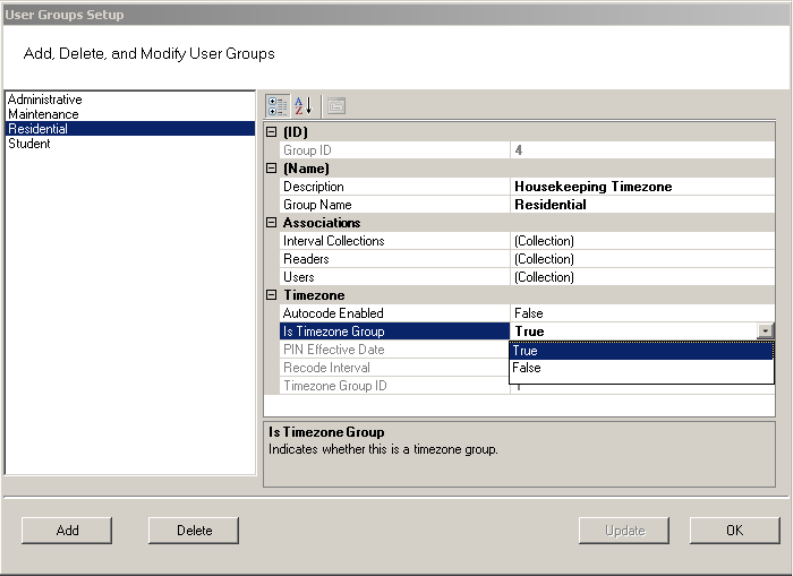
Figure 75 Creating a Timezone User Group
3 Select Add. Group1 is created.
4 In the Name Category, Description, enter a description for the group, for ex-
ample: Housekeeping Timezone.
5 In the Group Name, replace Group1 with the name of your new user group, for
example, Residential.
6 Under Timezone, change the Is Timezone Group default setting from False to
True. Select Update to continue creating groups.
7 Select OK to save the new Timezone group.
Once you have created a Timezone group, you will need to set up access times
to apply to that group. For more information about Timezones and Timezone User
Groups, see “Configuring Timezones” on page 137.
108
Credential Settings
Keypad credentials, magnetic card settings, and proximity card settings are all set in
this category. Detailed steps are presented in the following sections.
Keypad Credential Length
If your access system will have or currently has cards encoded with keypad cre-
dentials, you may set the number of digits required here.
Note Keypad credential length must be set before you add users to the system.
Perform the following steps to set the Keypad Credential Length.
1 In the Segment Tab, under the Credential Settings category, click in the Keypad
Credential Length field.
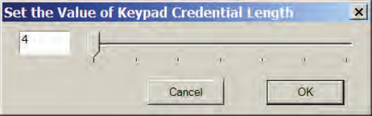
2 Click the ellipsis button at the far right of the field. The Set value of Keypad
Credential Length dialog box opens.
Figure 76 Setting the Credential Length
3 Enter the length or slide the bar to select the position of the Keypad Credential
length you will use on segment cards.
4 Select OK to save your settings and exit the box.
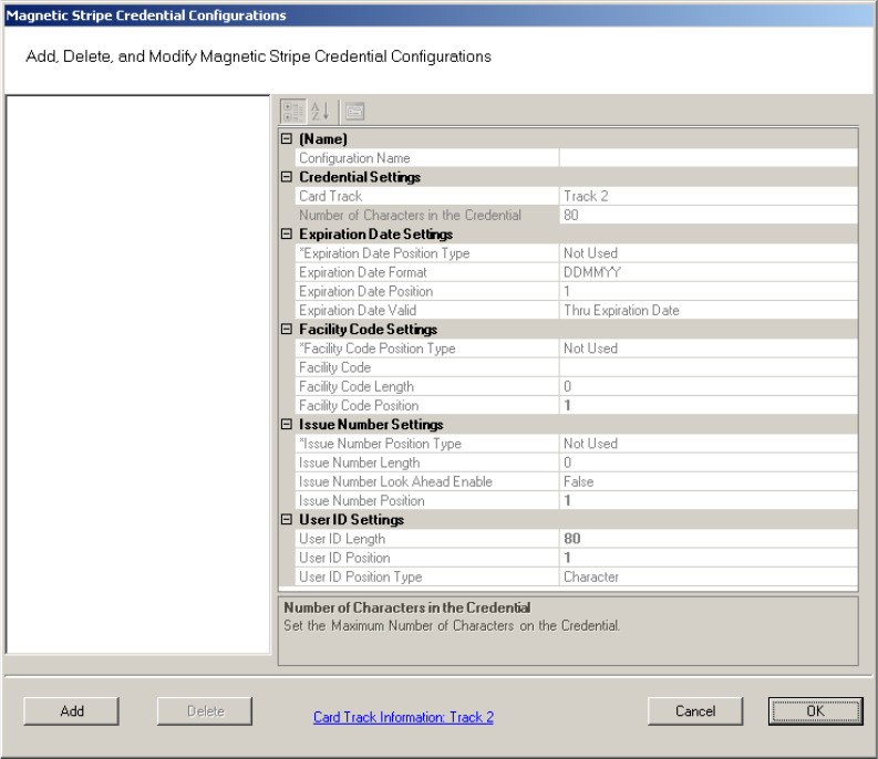
Magnetic Stripe Credential Configurations
Before Magnetic cards can be used in the system, you must configure AMS to
accept the card types and settings. Figure 77 shows the Magnetic Stripe Credential
Configurations Window. Default settings will be sufficient for most systems.
Most users will use Track 2 cards and will not need to set up any type of advanced
card parameters. Wi-Q AMS default Expiration Date, Segment Code, and Issue
Number settings to Not Used, and no other changes need to be made.
Stanley Security Solutions currently stocks and provides Track 2 or Track 3
magnetic cards. These cards conform to ISO standards and can be ordered pre-
encoded or blank. The system can be used with either Track 1, Track 2, or 3 cards,
however you can only encode 1 type within the same segment.
109
Figure 77 Magnetic Stripe Credential Configurations
If you must make changes to the default settings, click Add to create a new
Magnetic Stripe card configuration, and give a name to your configuration in the
Configuration name field.
110
Credential Settings
Wi-Q AMS can be configured to accept coding from existing Track 1(210 BPI),
Track 2 (75 BPI) or Track 3 (210 BPI) cards as long as the code does not exceed the
maximum number of characters for that track and/or controller. Magnetic cards
are configured as Track 2 by default. Perform the following steps to change to
change the segment track setting for encoding cards:
1 In the Magnetic Stripe Credential Configurations window, click the Card Track
Information link at the bottom of the window.
2 The Define Magnetic Stripe Card Track Information window opens. Specify the
desired track from the dropdown menu. Then click Finish.
3 Click OK to exit the Magnetic Stripe Credential Configurations window.
4 In the Segment tab, click Update at the bottom right to update your segment.
Card Track Limits
Wi-Q AMS is flexible and may accept coding from existing Track 2 or Track 3
cards as long as they do not exceed the maximum number of characters for that
track and/or controller. These characters include any digits and field separators,
however they exclude the starting and ending sentinels. Refer to the Stanley
Security Knowledge Base or contact Technical Support for controller hardware
track limits.

111
Character codes and counts
The software recognizes data on a magnetic card stripe using ANSI standard
codes formatted to either a field separator or character count. Following is a brief
description of each type.
Field Separator — Field Separator (FS) character, generally represented as an
equal sign (=) to separate two independent data fields. A card using this method
might have the owner’s individual ID encoded at the beginning of the stripe fol-
lowed by the FS character then the global segment ID. The fields can be in either
order, or there can be more than two fields, which could be required for compat-
ibility with pre-existing systems, and any one of them can be set up as User ID,
Segment ID, Card Issue ID, or Expiration Date.
Following is an example of encoded data using field separators on Track 2.
Figure 78 Data Fields
;
1576=3492657182=0=060113
FIELD 1: Facility Code = 1576
FIELD 2: User ID Number (Max 19 digits)
ID Number = 3492657182
FIELD 3: Card Issue ID
0 = First Issue
FIELD 4: Card Expiration Date
060113 = MMDDYY = June 1, 2013

112
Character Count — You can set up a character count from the beginning of each
ID. For example, the Segment ID could start at the beginning of the data stripe,
digit count of 1. If the Segment ID has eight digits, the User ID would be set to
start at digit count of 9. This method requires all data groups with exception of the
last one, to have a fixed number of digits. Following is an example of encoded data
using character counts on Track 2.
Figure 79 Character count fields
Note If you are not using the default settings for Magnetic Stripe Credential
Configurations, make sure that Expiration Date Position Type, Facility Code
Position Type, Issue Number Position Type and User ID Position Type are all set to
either must be set to “Field” (Field Separator) or “Character” (Character Count);
you cannot mix types.
;
157634926571820060113
Facility Code Starts at Character 1
Facility Code = 1576
User ID Number Starts at Character 5
ID Number = 3492657182
Card Issue ID Starts at Character 15
0 = First Issue
Card Expiration Date Starts at Character 16
060113 = MMDDYY = June 1, 2013
113
Expiration Date Settings
Perform the following steps to define a card expiration date.
1 In the Magnetic Stripe Credential Configurations window, under the Expiration
Date Settings category, click in the Expiration Date Position Type field.
2 Select either Character or Field from the drop-down list. The Expiration Date
Format, Position and Valid list boxes activate.
3 In the field next to Expiration Date Format, select the date format you need
from the drop down list (MMDDYY, etc.).
4 In the field next to Expiration Date Position, enter the value to represent either
the field position or the character number where the expiration date appears
on the card stripe.
5 In the field next to Expiration Date Valid, select either To or Thru Expiration
date.
6 Select OK to save your settings and exit the box.
Note If you use the character code format and select the six-digit expiration date
format, the value of your next setting (Facility Code Settings) must start with
character position 7. If you enter an incorrect value, the system will report an error
message. Review the “Character codes and counts” on page 111 if you need
clarification.
Facility Code Settings
Perform the following steps to define a facility code type, position and length.
1 Under the Facility Code Settings category, click in the Facility Code Position
Type field.
2 Select either Character or Field from the drop-down list. The Facility Code
fields below activate.
3 In the field next to Facility Code, enter your Facility Code number.
4 In the field next to the Facility Code Length, enter the length.
5 In the field next to Facility Code Position, enter the facility code position.
6 Select OK to save your settings and exit the box.
114
Issue Number Settings
You can issue a replacement card to a user in lieu of issuing a new User ID. The
Card Issue ID consists of one or two digits from 0 through 99. After using the card
with an incremented (higher number) Card Issue ID in a reader, that lock will no
longer accept cards with the same User ID that have a lower Card Issue ID.
Perform the following steps to define an issue number position.
1 In the Issue Number Settings category, click in the Issue Number Position Type
field.
2 Select either Character or Field from the drop-down list. The Issue Number
fields below activate.
3 Enter the Issue Number length.
4 Click the Issue Number Look Ahead Enable field, and select true or false from
the dropdown menu.
5 Enter the Issue Number position.
6 Select OK to save your settings and exit the box.
User ID Settings
You can specify the position of the User ID code in the credential number either
by character or field position. Perform the following steps to modify the User ID
Settings.
1 Enter the User ID Length.
2 In the User ID Position field, enter the position number.
3 In the User ID Position Type field, specify Character or Field.
4 Select OK to save your settings and exit the box.
5 Select Finish to save all your settings.
115
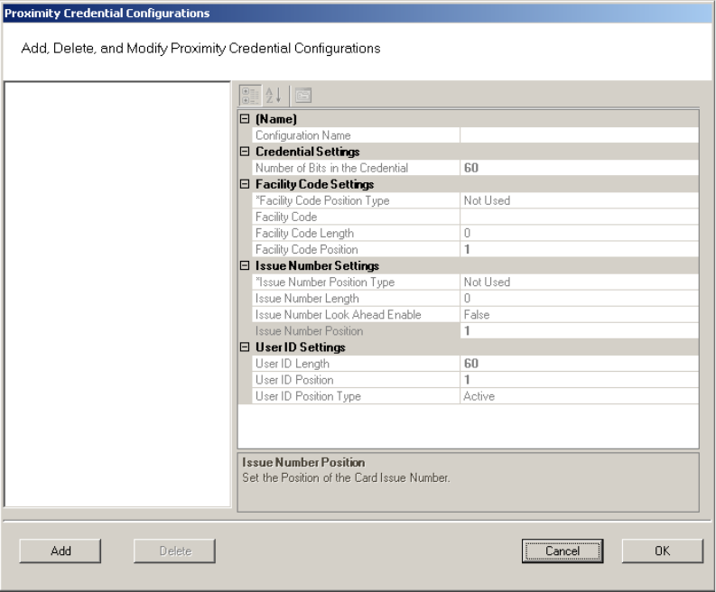
Proximity Credential Configurations
If you are using proximity cards in your system, you can add card configurations
by clicking on the Proximity Credential Configurations field and selecting the ellip-
sis button at the far right. Figure 80 shows the Proximity Credential Configurations
window.
Figure 80 Proximity Credential Configurations
To add a card configuration, perform the following steps.
1 Click Add. Give your new configuration a name in the Configuration Name field.
2 Under Credential Settings, select Number of Bits in the Credential. Change the
number to the right (default 60) to match the number of bits on your card.
3 If your card is configured to include the facility code, change Facility Code
Position type to Active. The facility code fields below will activate.
a Enter your facility code in the Facility Code field.
b Change the Facility Code Length to match the number of bits in your facility
code.
c Change the Facility Code Position to match your card.
Note Issue Number Settings are not configurable for proximity cards. Proceed to User
116
ID Settings.
4 Under the User ID Settings category, change the User ID Length to the number
of bits used for User IDs on your card. Set the User ID Position.
5 When finished, click OK.
Daylight Saving Settings
You can set Wi-Q AMS to automatically respond to Daylight Saving Time settings.
When you select North American as the Daylight Saving Type, the system de-
faults to standard Daylight Saving Time settings. When you select Europe as the
Daylight Saving Type, the system defaults to the settings for Europe. When you
select Southern Hemisphere, the system defaults to the settings for the Southern
Hemisphere. Once the settings are selected, the system will adjust to Daylight
Saving Time automatically.
To change Daylight Savings Settings, place the cursor in the field next to Daylight
Saving Type and select the type you wish to use. The settings below change to the
defaults for that setting.
I/O
If you are using input/output devices in your system, they are recognized and
defined similar to a Controller.
For example, if you are using a WAC to collect transactions from an alarm, you will
see it in your Segment Tree as a “Reader” when its associated Portal Gateway is
brought online. You can define and modify I/O events for the controller under I/O
References.
Adding and Modifying I/O References
1 In the Segment tab, click the I/O References field, and click the ellipsis button
at the far right. The I/O References Setup dialog box opens.
117
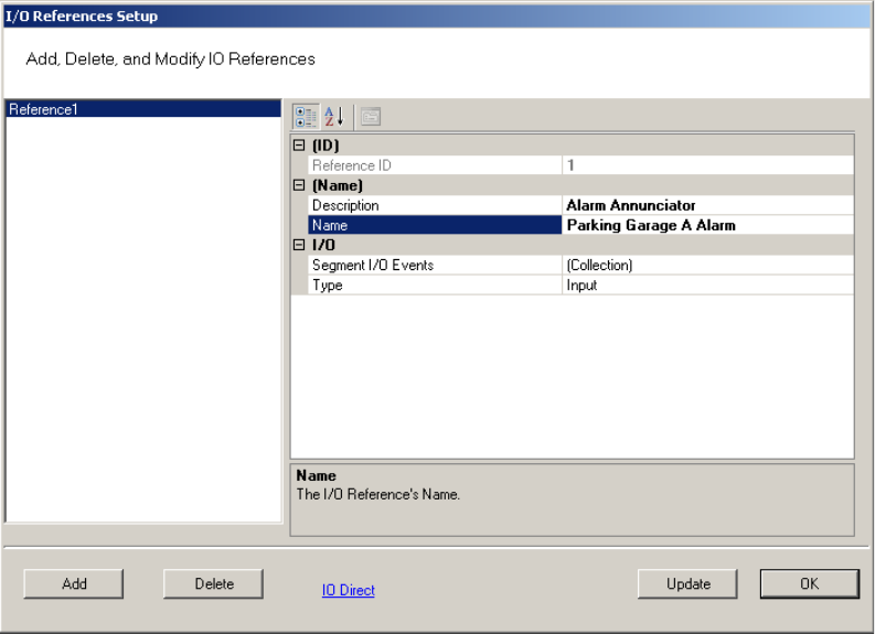
Figure 81 I/O References Setup
Here, you define an event and type for the reference. The system creates an I/O
reference point in the left column of the dialog box and assigns it a reference ID
number.
2 Click Add.
3 Under Description, replace the default description “Reference1’ with a descrip-
tion that will have meaning for your segment, such as Alarm Annunciator.
4 Under Name, replace the default name “Reference1” with a name that will have
meaning for your segment, such as Parking Garage A Alarm.
5 Under the I/O category, click the Segment I/O Events field and select the ellip-
sis button at the far right. This will open the I/O Events Setup window.
118
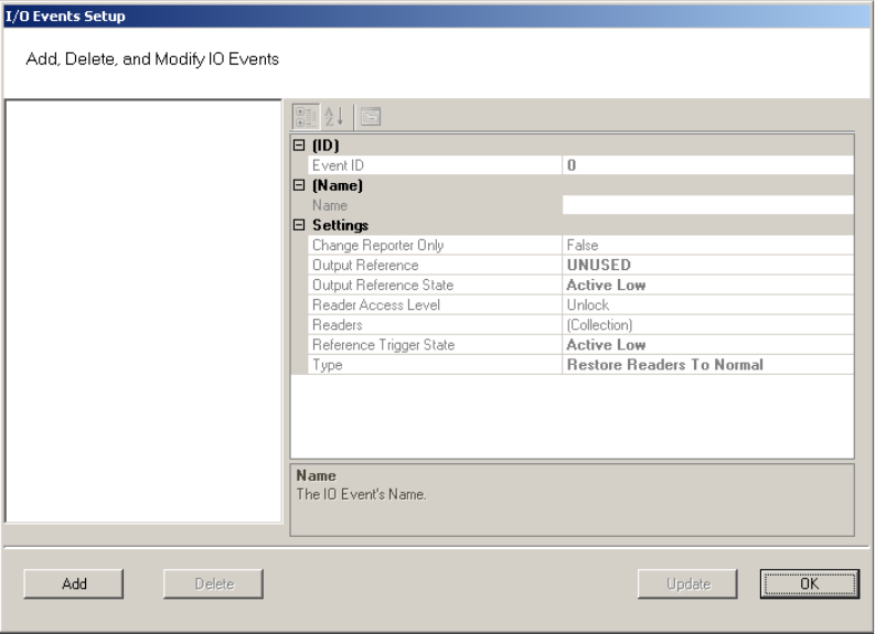
Figure 82 I/O Events Setup
From here you can create an event, check the device’s current state of operation,
define an access level, associate it with a reader in the system, define a trigger
state (high or low), and define the type of event to be triggered.
Note: The system recognizes the WAC as any other “reader” in the system. It will appear
in the referenced dialog boxes as a reader; however, you will recognize it by its
MAC address.
6 Click the Add button. The system creates an Event ID and adds it to the list in
the left hand column.
7 Enter a name for the event, such as Fire Alarm A.
8 Under the Settings Category, click the Readers field and click the ellipsis but-
ton.
9 This will open up a new window. See Figure 83. Select a device from the Read-
ers in Segment section that will be associated with the event.
10 Click Add << to add it to the list of Readers Associated with I/O Event list.
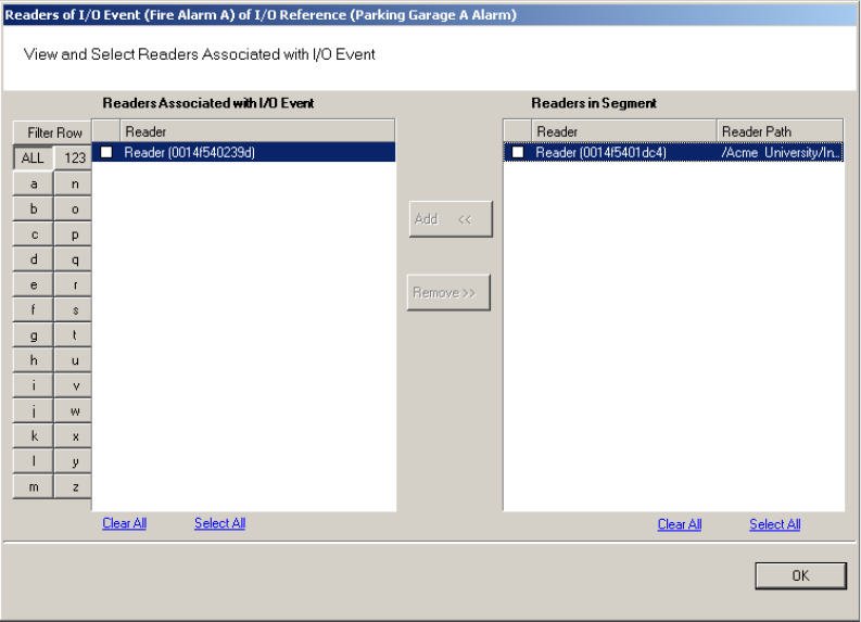
119
Figure 83 Associating an I/O event with a Reader
11 Click OK to save the association and return to the Setup dialog.
12 In the Reader Access level field, select either Unlock or Lockout from the drop-
down list.
13 In the Reference Trigger State field, select either Active High or Active Low
from the drop-down list (this reference will act as a toggle from one state to
the other).
14 Under Type, select the event type from the drop-down list.
Restore Readers To Normal
Change Output Reference
Override Reader Access Level
Override Timezone User Group Access
Restore Output Reference To Normal.
15 Click Update and continue defining devices then click Finish to save your set-
tings and exit the dialog box.
120
Misc
This category contains three fields (Contact 1, Contact 2, and Reference) that you
can use to store any miscellaneous information you that will be helpful to you and
your system. For example, you may decide to enter the phone number or email ad-
dress for Stanley Technical Support in case you experience technical difficulties.
PIN Settings
If your system will require user PINs, you may set the PIN length here. Perform
the following steps.
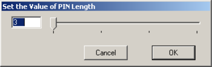
1 Click in the PIN Length field, and select the ellipsis button at the far right. The
PIN Length window opens.
Figure 84 Set the Value of PIN Length
2 Set the value to a number between 3 and 6 by typing it in or sliding the bar to
select the position of the PIN length you will use on segment cards. Then, press
OK.

121
Adding Users to the Segment
The system is now ready for you to add users. Follow the steps in this section the
first time you enter users, and each time you add a new user to the system. To get
started, navigate to the Users tab within the Configurator module.
Before You Begin
Before you begin adding users to the system for the first time, be prepared to ad-
dress the following items:
Note If you do not have this information, contact your System Administrator before you
begin.
If... Then...
You plan to use only keypad Controllers AMS assigns a unique keypad credential to each new
user and automatically registers it with the system.
You plan to use card readers You must know the card type and settings required for
that type.
You plan to use a serial scanning device at your
computer to register user credentials
The scanning device must be attached to the com-
puter com port and you must be able to identify that
port (Com1, Com 2) when you register the credential.
You plan to use local readers to register cre-
dentials
Know the reader name and locations to be used.
You plan to manually enter the credential
numbers
Have a credential number list or creating conventions
ready to enter.
122
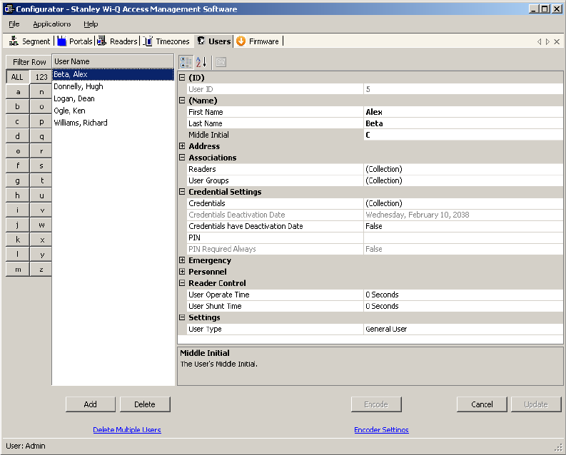
Users Tab Overview
Figure 85 Users Tab
In the Users Tab, all users currently in the system display in the list on the left. If
you have a large number of users, you can use the alphabet buttons on the far left
to quickly sort through the list. Users Categories display on the right. By default,
these categories display as shown; however you can click the A-Z sort button to
display categories alphabetically. Here you can add or remove users from the sys-
tem, set their credentials, and include any personal information needed to identify
that person in the system.
If an ellipsis button displays when you select a field, additional parameters are
available for selection. From here you will define user name and address informa-
tion and access parameters such as readers, user groups, credentials, PIN, and so
on.
Note If you see a need for additional fields to define for your Users, contact your System
Administrator. They can add more fields to the Users Tab, or create additional User
Fields unique to your organization.
123
The following sections describe each category in the Users Tab, and present steps
for adding and configuring users in the system.
ID — When you add a user, the system automatically assigns them a unique ID
and displays the number in the User ID field.
Name — Provides entry fields for Users’ first and last name and middle initial.
Adding a User Name
1 In the Users Tab, select the Add User button. In the ID category, the system will
display a new unique User ID.
2 In the First Name line, highlight and replace the default text (example: User1)
with a first name.
3 In the Last Name field, highlight and replace the default text
(“_New”) with a last name. Add a Middle Initial if needed.
Note The Update button will flash to remind you to update your settings. You can update
each time you add a user, or wait until all user information is added. The software
will automatically update your settings when you exit the Users tab.
User Defined Categories and Fields— If your segment has been configured with
user defined categories and fields, such as Address, City, Zip Code, enter the
information as configured.
Associations — In this category, you associate Users with Readers and User
Groups. This task defines which readers will recognize the User’s requests for
entry and exit. If User Groups have been created for your organization, these will
also be available for selection from the Associations category.
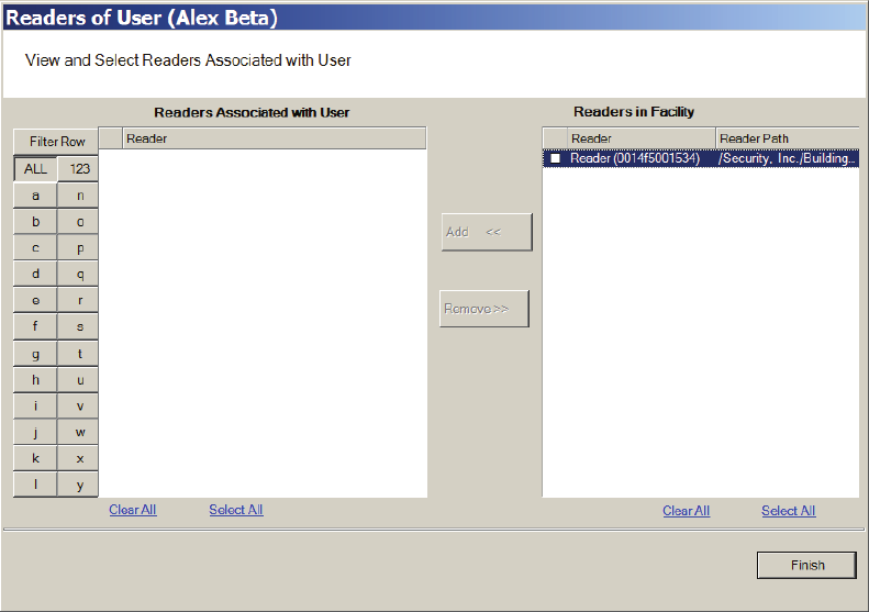
To associate a user with readers
1 In the Associations category, click inside the Readers field, and select the el-
lipsis button at the far right.
2 The Readers of User dialog box opens and displays a list of readers available to
the User.
Figure 86 Readers of User
124
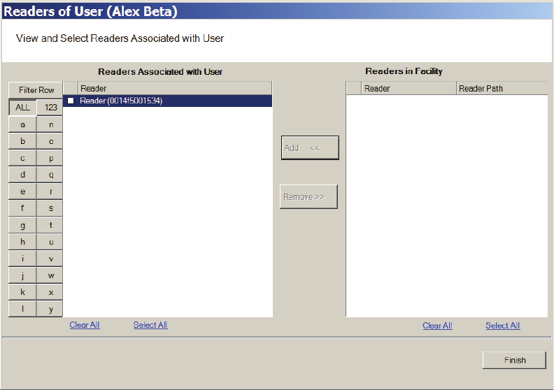
3 Select the reader(s) from Readers in Segment.
4 Select Add <<. The selected readers are moved from the Readers in Segment
list to the Readers Associated with User list on the left. You can associate a
user with any number of readers.
Figure 87 Selecting a reader to associate with a user
5 Select OK to save your settings and return to the Users Tab.
User Groups
If User Groups have been created for your segment, these will already be as-
sociated with readers. For example, a User Group may have been defined for
Laboratory Building 1. Laboratory Building1 might have six readers. By assigning
the User to the Laboratory Building 1 Users Group, they will automatically be as-
sociated with all the readers in that group.
A User Group may also be defined as a Timezone Group. Timezone User Groups
further define access levels for the Master Timezone. You can restrict access of
certain groups of employees to a specific time period. For example, you may have
a housekeeping group designated as a Timezone Group with restricted access
to dormitories from 8:00 a.m. to 4:00 p.m., weekdays only. You would then assign
Users from the housekeeping department to this group. Steps to add users to User
Groups are presented in the following section. For more information about creat-
ing Timezone Groups, see “Timezone User Group Collections” on page 142.
125
Perform the following steps to add a user to a User Group.
To add a user to a User Group
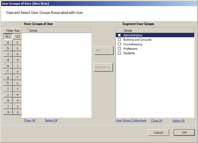
1 When adding or editing a User, in the Associations Category, click in the User
Groups field and click the ellipsis button. The User Groups of User dialog box
opens.
Figure 88 User Groups of User
2 Select the group(s) to associate with this user and click the Add << button. The
groups are added to the User of Groups list.
3 Select OK to save your selections and return to the Users Tab. You can add or
change User Groups for a user any time by returning to this list.
Credential Settings
Wi-Q AMS tracks individual requests for access or exit from the segment by their
unique credentials, and each request is recorded as a transaction in the database
for reference. Whether your organization uses keypad Controllers or card readers,
each user will be assigned a unique credential number. Under Credential Set-
tings, you will enter the credential ID and number, select a credential type, and set
additional parameters related to the credential type. You can add another level of
security by combining an individual’s credential with a personal ID number (PIN).
If your organization requires a PIN, you will enter them here. Credential setup is
a two-step process: First you will select the credential type to be used, then you
126
will register the credential.
Keypad Type — The default credential type in AMS is Keypad. When you add a
user to the system, the software assigns them a unique keypad credential num-
ber, then automatically registers it with the system. If your segment uses only
keypads, once you add the new user name, you can skip to Adding PINs and
Expirations Dates.
Card Type — If your segment uses card type credentials, you must select the card
type, enter the appropriate settings, and then register the credential number with
the system.
To select the card type
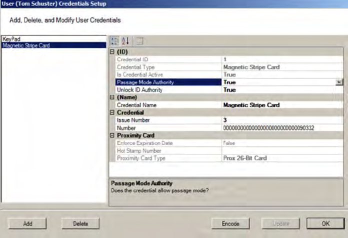
1 In the Users Tab, Credentials line, select the ellipsis button. The User Creden-
tials Setup dialog box opens. The credential types are listed on the left and the
categories available for each type are listed on the right.
Figure 89 Selecting a User Credential type
127
2 Select the type of credential the reader will use, for example, Keypad. The
credential options in the categories on the right will change, depending on the
type selected.
Passage Mode Authority — User credential has the authority to activate passage
mode with 2 entries.
1st Card Unlock Authority — User credential has the authority to leave the door
unlocked when in an ‘unlock with ID’ access mode.
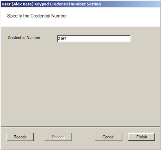
3 Under the credential category, click the Number field and click the ellipsis but-
ton. The Specify the Credential Number dialog box opens.
Figure 90 Enter a user credential number
4 If you wish to have the software generate a new number, select Recode. Or,
you may type in the user’s credential number. Click Finish. You can change the
credential number at a later date if needed.
5 Now you are ready to register the credential.
Note If the credential type you need is not in the list of card types on the left, you can
add one. See “Adding a Credential Type” on page 131.
Credentials Deactivation Date — You can define whether a user’s credentials
can be automatically de-activated based on an expiration date. This is useful, for
example, when entering credentials for a temporary employee or contractor. If the
credential can expire, select True from the drop-down list next to the Credentials
have Deactivation Date field, and then enter the de-activation date in the Creden-
128
tials Deactivation Date field. If the credential cannot be de-activated, select False
from the drop-down list. The default deactivation date is 26 years to ensure a
user’s credential is not inadvertently deactivated.
Registering the Credential
When you click on the Number field below the Credential category and select the
ellipsis button, the Specify the Credential Number dialog box opens. From here,
you can enter the credential number manually, scan the user’s card with a scan-
ning device connected to your computer, or specify a reader where the user will
scan their card. Steps to register each type of card are presented in the next few
sections.
Note If you use the reader scan method, the card used must be unassigned.
To register a Keypad credential
1 Keypad credentials are automatically registered by the system, and no further
steps are required.
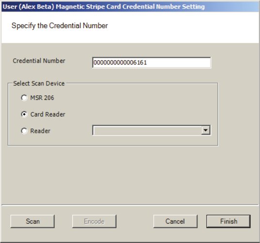
To register a Magnetic Stripe Card credential
1 From the User Credential Setup dialog box, select Mag Card from the list.
2 Click in the Number field and select the ellipsis button. The Users Magnetic
Stripe Card Credential Number Setting dialog box opens.
Figure 91 Entering a Magnetic Card credential number
129
3 Enter a Credential Number manually (must be less than 16 characters, zeros
will be appended) or select a scan device.
Using a scanning device to register a credential
You can use a scanning device connected to your computer to register a creden-
tial.
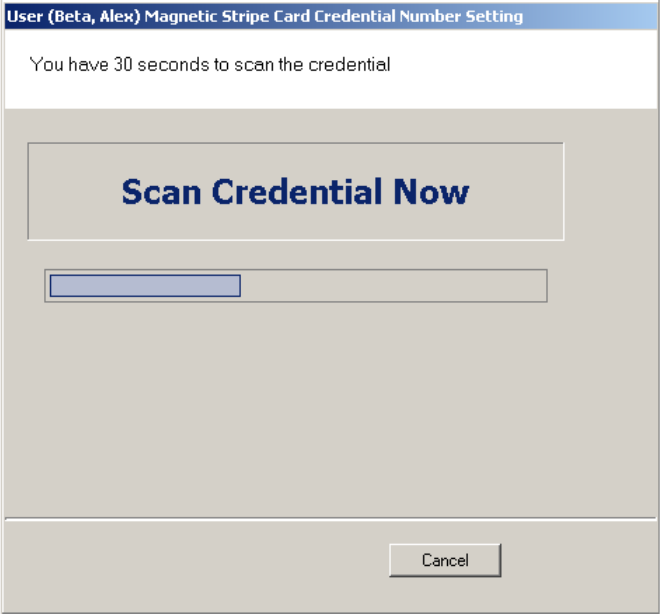
1 Select Card Reader. When you are ready to scan the card, select the Scan but-
ton. You will have 30 seconds to scan the card.
Figure 92 Scan Credentials
2 When recognized, the number will display in the Credential Number text box.
3 Select Finish and return to the Credential Setup dialog box.
Using a local reader
You can use a local reader to scan the card credentials.
1 Select Reader, and then use the drop-down list to navigate to the reader where
the card will be scanned. When you are ready to scan the card, select the Scan
button. You will have 30 seconds to scan the card. When recognized, the num-
ber will display in the Credential Number text box.
2 Select Finish and return to the Credential Setup dialog box.
130
Note You may need to expand the drop-down list to view all available readers. Use the
highlighted area in the lower right corner.
Registering a Prox card credential
In the Proximity Card category, review the Prox Card Type. If the default entry
is not the one you will use, select the field and use the down-arrow to select the
correct type from the list.
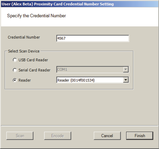
To register a Prox Card Credential
1 Select Prox Card from the list on the left. Click the ellipsis in the Number field,
under the Credential category. The User Proximity Card Credential Number
Setting dialog box opens
Figure 93 Entering a Proximity Card credential number
2 Enter a Credential Number manually (must be less than 16 characters, zeros
will be appended) or select a scan device:
USB Card Reader
If you have a MSR 206 USB Card reader connected to your computer, select MSR
206.
1 When you are ready to scan the card, select the Scan button. You will have
30 seconds to scan the card. When recognized, the number will display in the
Credential Number text box.
131
2 Select Finish and return to the Credential Setup dialog box.
Serial Card Reader
If you have a Serial Card Reader connected to your computer, select Serial Card
Reader and then select the appropriate com port from the drop-down list.
1 When you are ready to scan the card, select the Scan button. You will have
30 seconds to scan the card. When recognized, the number will display in the
Credential Number text box.
2 Select Finish and return to the Credential Setup dialog box.
Adding a Credential Type
At least one credential type must be defined for the system. The default credential
type in Wi-Q AMS is Keypad. If you use other than keypad credential types, you
can add them to the User Credentials Setup dialog box.
To add a card type to the list
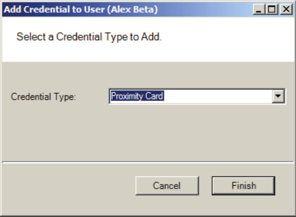
1 In the Users Credentials Setup dialog box, select the Add button. The Add Cre-
dential to User dialog box opens
Figure 94 Add Credential to User
2 Select the Credential Type from the drop-down list, in this case, Proximity Card.
3 Select Finish. The User <Proximity Card> Credential Number Setting dialog box
opens.
4 Now, you may manually enter a credential number or scan the credential with a
132
scanning device.
PIN
You can add a level of security by requiring PIN numbers in addition to creden-
tials for all users, or for specific Timezone Intervals. The default displays the PIN
number as asterisks in the fields; however you can choose to show the actual PIN
numbers.
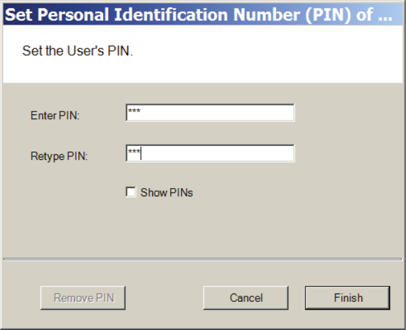
To add a PIN Number for a User
1 Under Credential Settings, click the ellipsis button in the field next to PIN. The
Set Personal Identification Number dialog box opens.
Figure 95 Set PIN of User
2 Select the Show PINs check box if you wish to view the numbers instead of
asterisks as you type them in.
3 Enter a PIN number for the user. Retype the PIN below.
4 Click Finish to save the PIN and exit the dialog box.
Reader Control
The system defaults the amount of time from the moment a reader unlocks until
it relocks, and the amount of time a door can stay open before an alarm will be
triggered. You can modify reader operate and shunt times for individual users. For
example, to be ADA compliant, a user who is in a wheelchair or uses a walker may
need more time to pass through a door. You can increase the shunt time for this
133
user.
To modify User Operate Time
In the Reader Control category, click the ellipsis button next to the User Operate
Time and select the amount of time you wish to leave the reader in the unlocked
position.
To modify User Shunt Time
In the Reader Control category, click the ellipsis button next to User Shunt Time
and select the amount of time you wish to allow for passage before an alarm will
be triggered.
Settings
Each segment user will be assigned a User and Access type, depending on the
tasks they perform and the access mode needed to perform those tasks. The
system supports three different types of users: General Users, Managers, and
Programmers. You can have up to 65,000 individual users in the system and they
can be of any User Type. User types are briefly described in the following para-
graphs.
General Users — The majority of users will be assigned as General Users. They
are allowed entry only when the access level is set to ID Required. General Users
never have access when the reader is in Lockout.
Manager — Managers are one of the most useful types of IDs. This User Type
provides the capability to change the access level of a reader with a few simple
key presses. These changes can and will be overridden by the time schedule or
another manager or programmer. A user with Manager privileges is always al-
lowed access to a reader. For example, when a segment requires an individual to
have access at all hours of the day without giving any extra privileges, that indi-
vidual will be assigned Manager Privileges
Programmer — Programmers can scan all channels at the keypad reader as well
as reset the reader to respond to keypad commands as in manager mode.
Note Managers and programmers are indistinguishable from a general user when no
keypad is present.
For a list of Manager and Programmer system override codes, see “System Over-
rides” on page 160.
134
To assign User Type
1 Under the User Tab, in the Settings category, select the field next to User Type.
2 Select a User Type from the drop-down list.
Portal and Reader Control and Messaging
Wi-Q AMS provides a number of features to reset and restore normal operations,
override locks and access levels, and temporarily remove reader association with
a Portal. These right-click functions send real-time instant messages to the hard-
ware from within the software.
Portal Controls
You can delete, reset and restore a Portal to normal operation without going to
the physical location of the Portal. These functions are accessible via a right-click
in the Readers tab of the Configurator module. You can also delete a Portal from
the system with the right-click function.
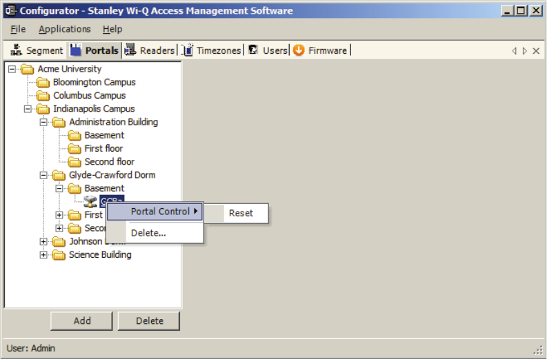
To access right-click Portal messaging
1 In the Portals Tab, right-click on the Portal and select the option from the drop-
down list. The software will ask you if you wish to proceed with the operation.
2 Click Yes. If the Portal is online, the operation is performed. If for any reason
the Portal is offline and unable to execute the command, the message will
become obsolete after five minutes.
135
Figure 96 Right-click Portal messaging options
Note Momentary unlocks and overrides must be recognized and executed by the Portal
within five minutes of the command or they become obsolete. This feature ensures
that commands executed during period when the hardware cannot respond are
not executed when the hardware is back online.
Reader Controls
You can delete, reset and restore a reader to normal operation without going to
the physical location of the reader. In addition to these commands, you can mo-
mentarily unlock, override the access level, perform a deep reset and remove the
reader’s association to a Portal all from within the software. These functions are
accessible via a right-click in the Readers tab of the Configurator module. You can
also delete a reader from the system with the right-click function.
Note To delete more than one reader at a time, hold down the control key (CTRL) and
select using the left mouse key.
To Access Right-Click Reader Messaging
1 In the Readers tab Segment Tree, right-click on the reader and select the option
from the drop-down list. The software will ask you if you wish to proceed with
the operation.
2 Click Yes. If the reader is online, the operation is performed. If for any reason
the reader is offline and unable to execute the command, the message will
136
become obsolete after five minutes.
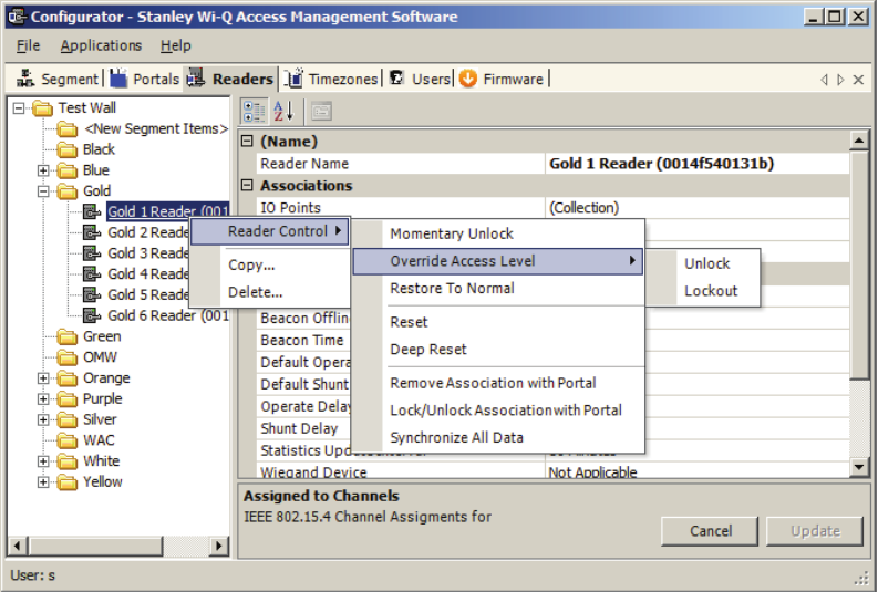
Figure 97 Right-click reader messaging options
Momentary Unlock — A user with appropriate permissions can override the stan-
dard Timezone conditions to temporarily unlock the door controlled by a reader.
The reader goes through a normal unlock-lock cycle where the default shunt and
operate times apply. As soon as the command is executed, the standard Timezone
conditions are restored.
Override Access Level — A user with appropriate permissions override the
reader’s access level. The override can be defined to last until the next timezone
interval occurrence or to remain until a restore to normal message is sent. As
soon as the command is executed, the standard Access Level conditions are
restored.
Restore to Normal — Immediately restores all standard normal operation.
137
Reset and Deep Reset — These options allow you to perform a reset and a deep
reset on a reader from within the software. The function is the same as perform-
ing a manual reset or deep reset at the reader hardware.
Remove Association with Portal — This command is useful when the reader has
associated with a different Portal or is being removed from the segment. When
you remove the reader’s association with the assigned Portal, it will search for
another Portal and resume communication.
Lock/Unlock Association with Portal — Locking a reader’s association with a
Portal will disallow its communication with other Portals. Unlocking an associa-
tion will re-allow communication with other Portals in range.
Synchronize All Data — This command will resend all reader information to the
Portal and update the reader hardware.
Note All overrides must be recognized and executed by the Portal within five minutes
of the command or they become obsolete. This feature ensures that commands
executed during period when the hardware cannot respond are not executed
when the hardware is back online.
Configuring Timezones
For the greatest majority of facilities, the default access level provided in the
Master Timezone gives you all the options you need to manage your segment.
The system works by defining different access levels at a controller rather than
different times of day the segment is locked or unlocked. However, it may become
necessary to define a new Timezone under certain circumstances. For example,
you may want to define a separate Timezone for a specific set of readers that
would operate on a totally different schedule from the main system. For this ap-
plication, you would create a different Timezone and then assign the readers to
that Timezone.
Timezones are created and configured in the Timezones tab within the Configura-
tor module. Three sub-tabs exist inside the Timezone tab:
Interval Collections — this is a collection of recurring ranges of time and days
of the week, such as 6:00 am to 6:00 pm weekdays AND 8:00 am to 8:00 pm
weekends.
Reader Control — this is where you assign access levels to readers and deter-
mine how the reader will operate during assigned timezone intervals.
User Group Collections: this is where you can add user groups to a collection
and define timezone intervals to the collection.
138
Note Readers can be assigned to only one Timezone.
To create a Timezone Interval Collection
1 Select the Interval Collections Tab under the Timezones Tab. The Interval Col-
lection window opens.
2 Click the Add button to create a new Timezone Interval Collection.
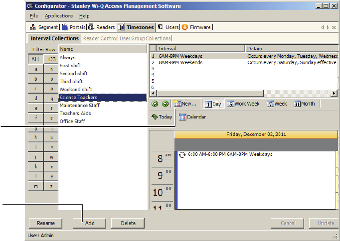
3 Click the New button to create a new interval.
Figure 98 Interval Collection
4 The Interval Configuration window opens.
Click New to
create a new
interval.
Click Add to
create an Interval
Collection.
139
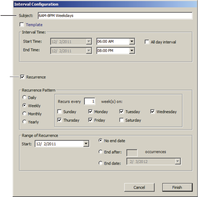
5 Enter a brief name for the Interval.
6 Select the Start and End Time of the Interval.
7 Click the Recurrence checkbox.
Figure 99 Interval Configuration
8 Select the Recurrence Pattern of the Interval.
9 Select the Range of Recurrence for the Interval.
10 Click Finish to save your new Interval. This Interval is now listed as one of the
intervals for the Interval Collection.
11 Repeat steps 3 to 9 to create other Intervals until the Interval Collection is
complete.
Name the
Interval. Tip:
usually good
practice to
name Intervals
by time ranges.
Click Recurrence if
the interval repeats.
140
Timezone Interval Template Feature
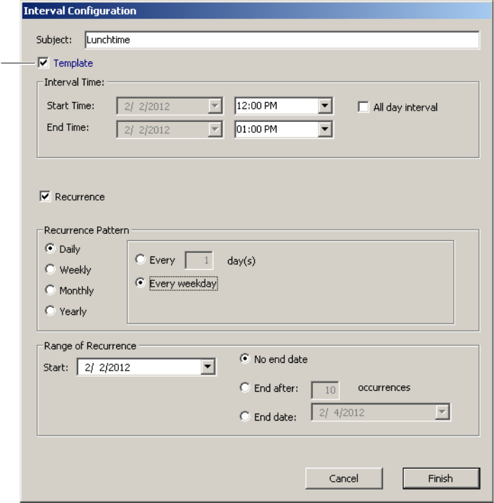
At the top of the Interval Configuration window, there is a “Template” checkbox.
Selecting this box will allow the timezone interval you configure to be used as a
template for other intervals. For example, if you create a “Lunchtime” interval col-
lection between 12pm and 1pm, and you select the “Template” checkbox (Figure
100), you can add that interval to an existing collection.
Figure 100 Interval Configuration Template
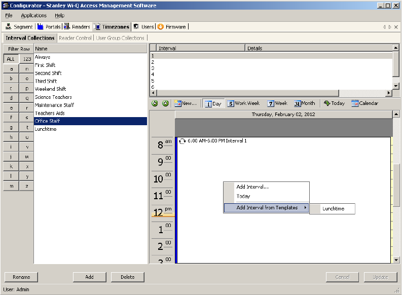
To add the “Lunchtime” interval to another collection , select the existing inter-
val collection from the list at the left, right-click in the calendar area, and select
“Lunchtime” from the Add Interval from Templates options. In our example, we
add the Lunchtime interval to the Office Staff Interval Collection. See Figure 101.
Template
141
Figure 101 Add Interval from Templates
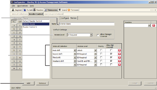
To create a Timezone Reader Control
1 Select the Reader Control Tab under the Timezones Tab. The Reader Control
Window opens.
2 Click Add to create a new Reader Control.
3 Enter a brief name for the Reader Control.
4 Select the default Access Level that will be operate for the Reader Control.
This access level can be overridden for specific Interval Collections.
5 Select the Interval Collections when the Reader Control will operate.
6 Use the red X to delete the interval collection if needed.
7 Click Update to complete the Reader Control.
8 Select the Readers that will operate under this Reader Control.
142
Figure 102 Reader Control
Timezone User Group Collections
You can create up to 32 Timezone User Groups to further define access levels for
the Master Timezone. You can restrict access of a certain group of employees to a
specific time period. For example, you may want to create a housekeeping group,
designate it as a Timezone Group, and then restrict access to dormitories only from
8:00 a.m. to 4:00 p.m., weekdays. This is a two step process. First, you will create a
Users Group and designate it as a Timezone Group; then you will define the Timezone
Interval for the new Timezone Group (you may want to review User Groups before
starting this task)
Name the
Reader Control.
Select what access
level is required for
this Reader Control.
Select the Interval
Collections when
the Reader Control
will operate.
Click Add to
create a new
Reader Control.
143
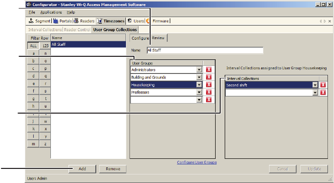
To create the Timezone User Group Collection
1 Select the User Group Collection Tab under the Timezones Tab. The User Group
Collection window opens.
2 Click Add to create a new User Group Collection.
3 Enter a brief name for the User Group Collection.
4 Select the User Groups that will be a part of the User Group Collection. You
must have set up User Group for the selections to be available.
5 Select the Interval Collections when the User Group Collection will operate.
You must have set up Interval Collections for the selections to be available.
6 Use the red X to delete the association of User Groups or Interval Collections
as needed. This will not delete the User Group or Interval Collections, it will
only delete the association.
7 Click Update to complete the User Group Collection.
Figure 103 Creating the timezone user group collection
Name the User
Group Collection
Select what what
User Groups will
make up the User
Group Collection
Select the Interval
Collection when the
User Group Collec-
tion will operate.
Click Add to
create a new
Reader Control.
144
6 Using and Managing the System
Wi-Q AMS and Omnilock provides powerful tools to manage your system: Con-
figurator, Transactions, Statistics Monitor and Reports.
If you are the Program Administrator responsible for setting up communications
between the software and system Portals and Controllers; you will spend most
of your time using Configurator. If you are in personnel or security, you may be
the person who adds users to the system and gives them access privileges and
IDs. You will spend most of your time on the Users tab of Configurator. If you are
responsible to oversee security for your organization, you will monitor all access
and alarm activity using Transactions. If you are the person responsible to ensure
the system is operating at maximum performance, you will use the Statistics
Monitor. If your organization is small, you may use all three! You can access all
applications from the Configurator main menu. You can also access these applica-
tions from the Windows Start Menu under Stanley Security Solutions.
145
Wi-Q AMS and Omnilock Configurator
The following sections describe the essential functions you can perform using
Configurator.
Launching Wi-Q AMS Configurator
When the software is loaded onto your computer, it places a shortcut to AMS on
your desktop.
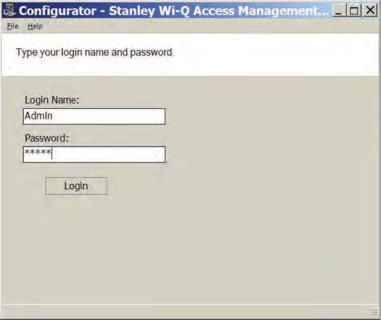
1 Double-click the Configurator icon to start the application. The splash screen
appears briefly, then the Login dialog box opens.
Figure 104 Logging in to Configurator
If you are a AMS User, your System Administrator or IT representative must
provide you a Login Name and Password. You will need this to login to the Con-
figurator. If you are a System Administrator, see “Logging in to Configurator” on
page 63 for more information about launching the software for the first time.
146
To Login to the Wi-Q AMS Configurator:
1 Enter your case-sensitive Login Name and Password.
2 Select Login. Configurator opens at the Segment tab.
3 If the System Administrator has created only one segment, you are ready to
begin. If more than one segment has been created, select the segment from
the drop-down list. Any elements you access in Configurator will be directed to
that segment.
WARNING: Once the System login and password have been personalized for your
segment, it is important to record the information in hard copy form and safeguard it
in a location known to management.
Managing Application Users
Wi-Q AMS and Omnilock ‘Application Users,’(AMS Users) as opposed to
‘cardholders,’ are those individuals who will operate one or all of software ap-
plications. For example, an application user might be a person in the Security
department who will use only the Transactions software to monitor system
access activity. Another AMS User might be a person in Human Resources or Ad-
ministration who is assigned to add users to the system or change their settings.
AMS Users must be added to the system as cardholders because they will re-
quire some type of physical access to the segment. However, they must also be
assigned as AMS Users and be given User names and Passwords if they are to
access and operate application software.
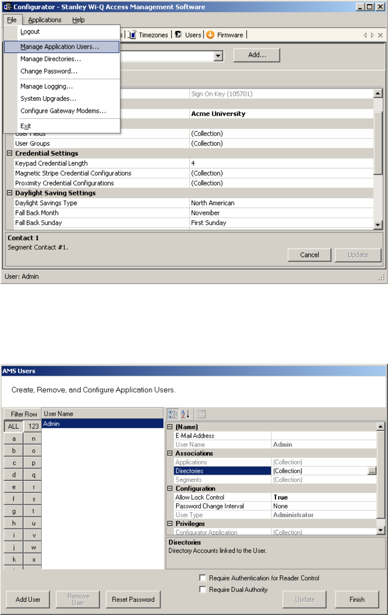
Access the Manage Application Users features via the Configurator File Menu.
147
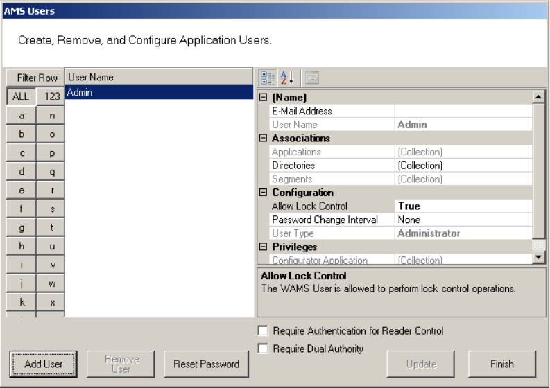
To Manage Applications Users:
1 From the Configurator main screen, select File>Manage Application Users. The
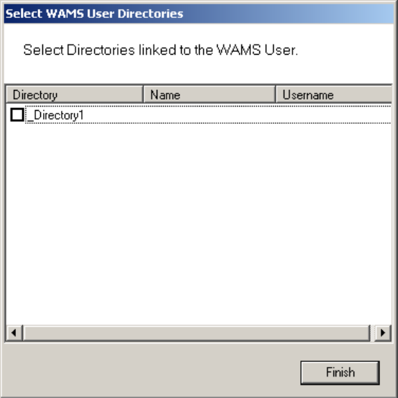
AMS Users dialog box opens.
Figure 105 AMS Users
From here you can add or remove an AMS User, associate them with applica-
tions and specific facilities, and configure their lock control privileges, password
change interval and assign a User Type. You can select whether require authenti-
cation for reader control or require dual authority for this user.
To add an AMS User:
1 In the AMS Users dialog box, click Add User. The system creates “User1” in
the left column.
2 In the Name category on the right, enter an e-mail address (optional), and the
user name.
3 Under Associations, click the Applications field, then click the ellipsis button at
the far right.
4 Select which application(s) the User will have access to. Then click Finish.
5 In the Directories field, click the ellipsis button. Select the directories linked to
the User. Then, click Finish.
6 In the Segments field, click the ellipsis button. Select which segments the User
148
will have access to and supply contact information as needed.
7 Under the Configuration category, in the Allow Lock Control field, select either
True or False from the drop-down list.
8 In the Password Change Interval field, select a change interval from the drop-
down list.
9 In the User Type field, select a User Type from the drop-down list. (User Types
are defined in the following paragraphs.)
10 If the user will require Authentication for Reader Control or Dual Authority,
select these options at the bottom of the sheet.
11 Click Finish to save your settings.
User Types
AMS Users can be one of four User Types: Administrator, Manager, Service, and
General. You will be assigned a User Type depending on which applications you
will log in to and operate.
Administrator — has access to all applications and all segments. This User Type
would be assigned to a System Administrator, that is, someone who is responsible
for set up and configuration.
Manager — has access to all applications. This type would, for example, be as-
signed to someone responsible for adding users to the system. As an additional
security measure, this type could be restricted to access specific segments only.
Service — has access to Transactions and Statistics Monitor. This User Type can
also be restricted to specific segments only, if needed.
General User — has access only to the Transactions and Reports applications for
specific facilities. This user type would be assigned to someone in Security for
example, who will monitor daily entry and exit activity and system alarms. They
can not access the Configurator application.
Once an Administrator has logged in to the system, they can add AMS Users to
the system. If you are designated as an AMS User, you will be assigned a login
User Name and Password to access the software application(s) you need.
149
Linking AMS Users’ Windows Accounts to Configurator
You can change the Configurator login settings so that your Windows account is
linked to Configurator. This way, when you are logged into your Windows account,
you won’t need a login ID or password when signing in to Configurator.
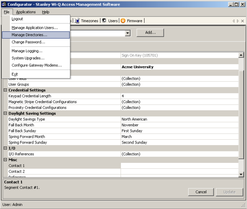
To link your Windows account to Configurator, perform the following steps.
1 From the Configurator File menu, select Manage Directories.
Figure 106 Manage Directories
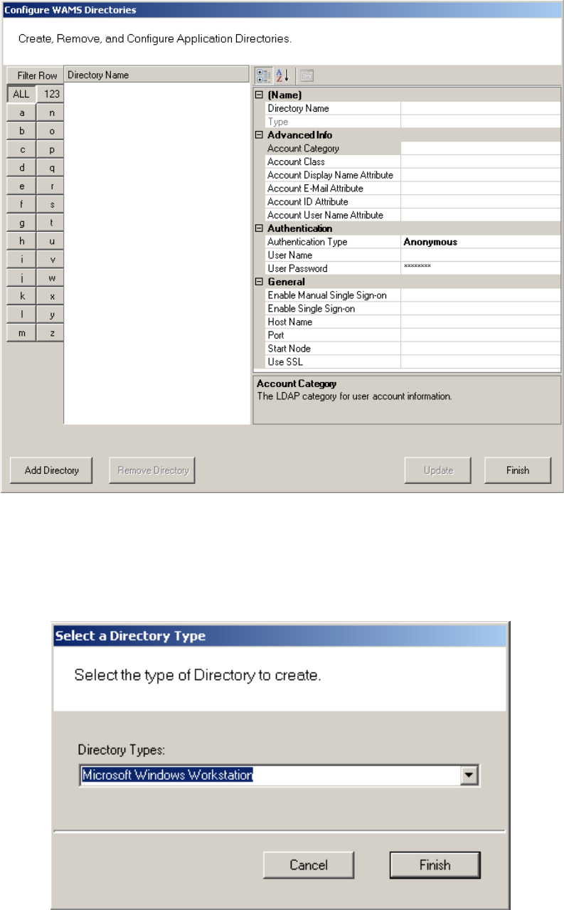
2 The Configure Directories dialog box opens. Click on Add Directory.
150
Figure 107 Configure Directories
3 The Select a Directory Type window opens. From the Directory Types drop-
down list, choose Microsoft Windows Workstation. Then, click Finish.
Figure 108 Select a Directory Type
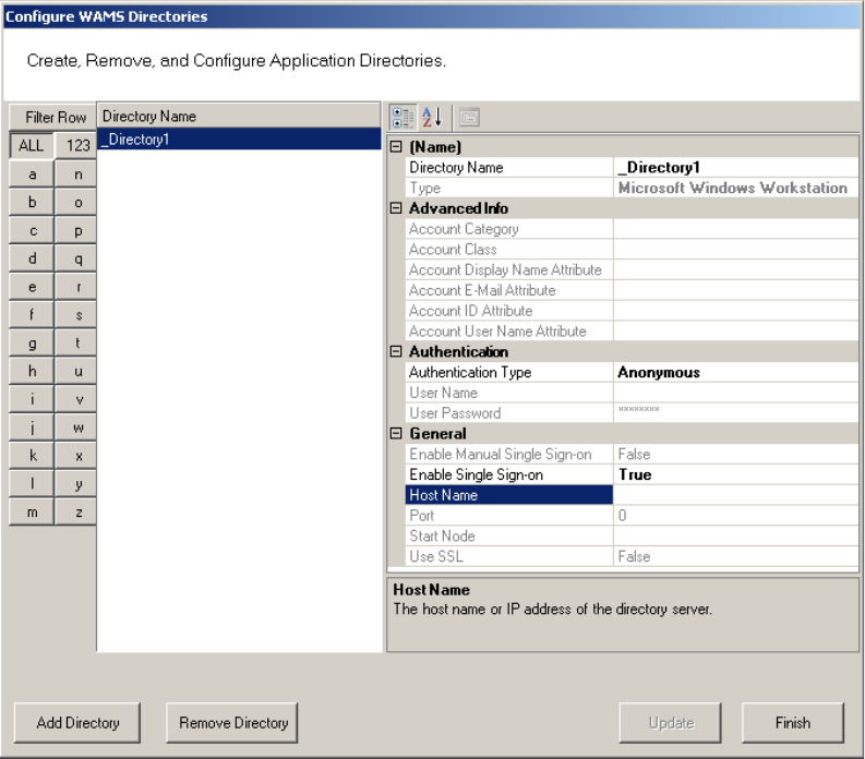
4 In the Directory Name field, specify a name for the new directory or leave in
151
the default name. In the Host Name field, under the General category, type in
the computer name of the host. Then, click Finish.
Figure 109 Directory and Host Names
152
5 From the Configurator File menu, select Manage Application Users.
Figure 110 Manage Application Users
6 The AMS Users dialog box opens. Click in the Directories field, under the As-
sociations column, and select the ellipsis button.
Figure 111 AMS Users
153
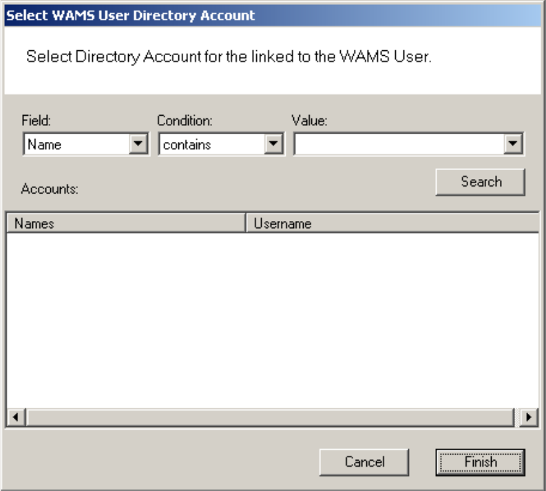
7 The Select User Directories window opens. Select the directory you created
previously.
Figure 112 Select User Directories
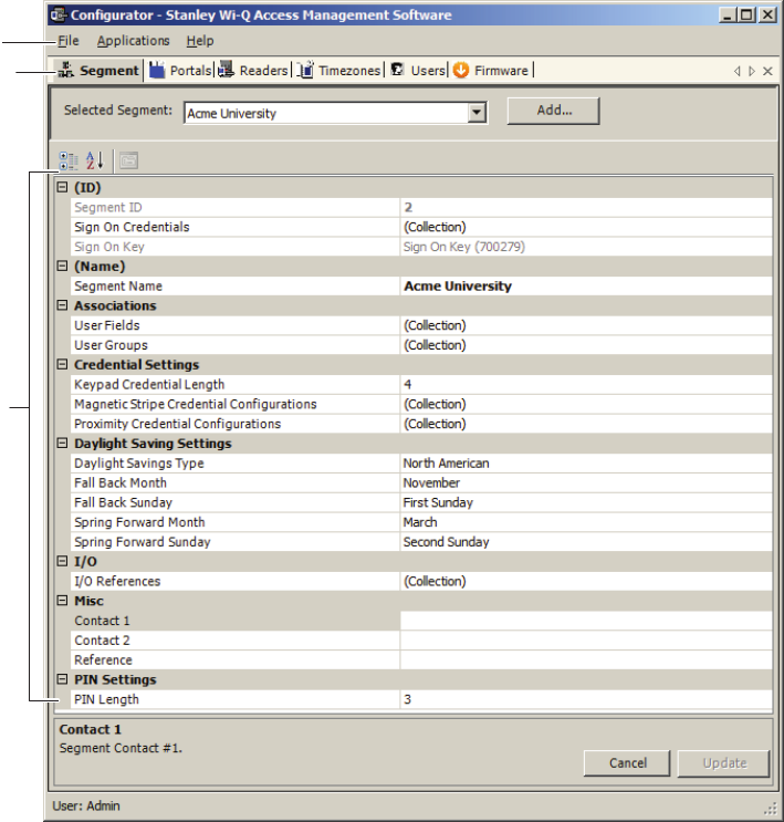
8 This will open the Select User Directory Account dialog box. Select Search,
and a list of users will be generated below. Select the desired Windows user
and then click Finish.
154
Figure 113 Select User Directory Account
9 Back in the Select User Directories window, the directory will now have a
checkmark. Click Finish.
As long as you are logged into Windows using the account you linked to in the
previous procedure, you will not be prompted to input a login ID and password the
next time you log into Configurator.
155
Configurator Overview
The following sections provide a brief overview of the Configurator module’s Dis-
play and Tab options.
Display Options
All tasks in Wi-Q AMS and Omnilock start from the Configurator, which has six
tabs: Segment, Portals, Readers, Timezones, Users, and Firmware. AMS operates
in the Windows environment using its standard Windows conventions. You can
use Configurator full screen or resize the window using the min/max buttons in
the top right corner of the window.
Following is the Segment Tab in minimized view with the scroll bar visible. This is
a useful option if you must run a number of other applications on your desktop and
need more space on your desktop.
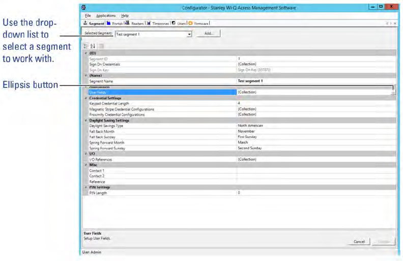
Figure 114 Segment Tab
In the Segment and Users Tabs, you can display items by category or sort alpha-
File Menu
Tab Options
Categories
156
betically. This is useful when displaying the Configurator in full-screen view. A
number of global operations are also available from the program File menu.
Segment Tab
Most Segment set up tasks are performed in the Segment Tab, Figure 114. Here,
the Program Administrator will create User Groups and configure the software to
work with the type of segment access cards or keypad credentials you will use.
If your Program Administrator has created more than one segment, you will first
select a segment to work with in the Segment Tab before moving on to work in the
other tabs.
Once you select a category within Configurator, you can use the ellipsis button to
configure additional settings.
Figure 115 Segment Tab Categories
157
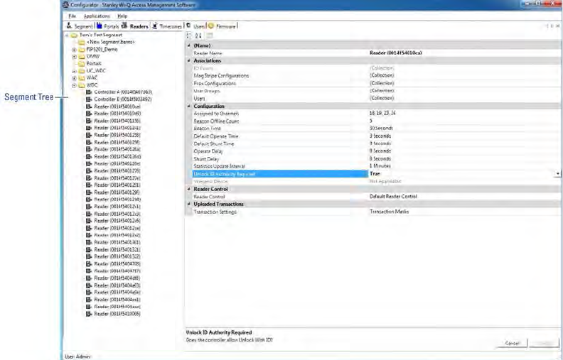
Portals and Readers Tabs
The Portals and Readers tabs displays the Segment Tree, which is a visual rep-
resentation of all Portal Gateways, Controllers, and I/O devices connected to the
software. Once the devices are organized in the Segment Tree, the various paths
to associate Controllers and Portals are available when you add new users to the
system.
Information about creating the Segment Tree and assigning devices to the vari-
ous folders in the tree is presented in Chapter 4, “Configuring Segments, Portal
Gateways and Controllers” on page 62. Typically, only the Program Administra-
tor will perform tasks using the Readers Tab, Figure 116.
Figure 116 Readers Tab
158
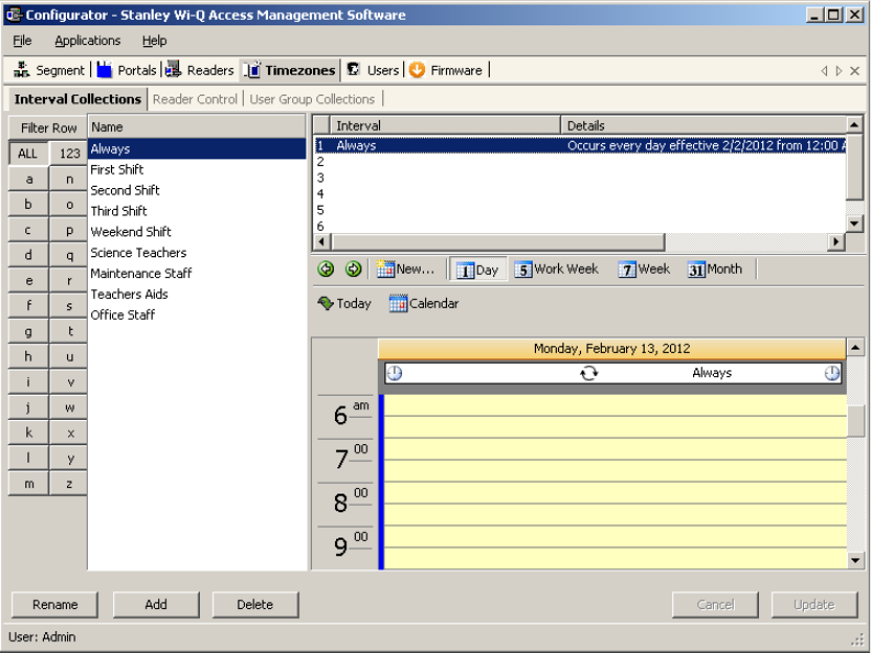
Timezones Tab
The software automatically assigns all Controllers to a Master Timezone. Your
Program Administrator can create any number of Timezone Intervals Collections
and Timezone User Group Collections to modify user access within the Master
Timezone. The Timezones tab displays the default Master Timezone, a calendar
that operates similar to Microsoft Outlook, and any Timezone User Groups that
have been created.
You can choose to display the calendar detail as one day, a work week, a full week
or by the month, or click on the calendar to display a specific date.
More information about creating Timezone Intervals and Timezone Groups is pre-
sented in later in Chapter 5, “Configure AMS Software (Task 11)” on page 96.
Figure 117 Setting up the Timezones
159
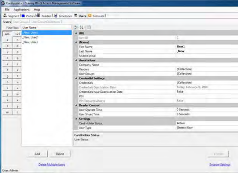
Users Tab
If you have been assigned responsibility to add or maintain general cardholder
users of the system, your tasks will be performed in the Users Tab. All users
currently in the system are displayed in the column at the left. To display a User
profile, simply select their name from the list.
Figure 118 Users Tab
More information about adding users to the system is presented in Chapter 5,
“Configure AMS Software (Task 11)” on page 96.
Firmware Tab
Firmware updates will be sent to you periodically by Stanley Technical Support.
You can upload these firmware files to your database by using the System Admin-
istrator Application, and then you can send the updates to your hardware from the
Configurator’s Firmware Tab. See “” on page 177.

160
System Overrides
Manager Override at Keypad Controller
When an AMS User is assigned the Manager Type, that user can change the cur-
rent access level at a Controller with a keypad. Once their credential has been
presented to a Controller and it has cycled, the following keys can be used to
change the Controller’s access level:
Note MC refers to Manager Credential.
Item WDC WAC Omnilock Function
Manager
Code
MC# MC MC Momentary Unlock.
Restore to
Normal
MC# + 0# MC + 0000 MC + 0 + CL Return to normal operation from an
override.
Toggle with
ID
MC# + 1# MC + 1111 MC + 1 + CL Places the device in a mode
to toggle between locked and
unlocked with a credential.
Unlock MC# + 2# MC + 2222 MC + 2 + CL Places the device in an unlocked
state.
Unlock with
ID
MC# + 3# MC + 3333 MC + 3 + CL Places the device in a mode to
unlock with credential.
Unlock with
ID and PIN
MC# + 4# MC + 4444 MC + 4 + CL Places the device in a mode to
unlock with credential and PIN.
ID
Required
MC# + 5# MC + 5555 MC + 5 + CL Places the device in a mode where
a credential is required to enter.
PIN
Required
MC# + 6# MC + 6666 MC + 6 + CL Places the device in a mode where
a PIN is required to enter.
Facility Card MC# + 7# MC + 7777 MC + 7 + CL Places the device in a mode where
all credentials with the correct
facility ID have access.
Lockout MC# + 8# MC + 8888 MC + 8 + CL Places the device in a mode where
only manager credentials have
access.
Toggle with
ID and PIN
MC# + 9# MC + 9999 MC + 9 + CL Place the device in a mode to
toggle between locked and
unlocked with a credential and
PIN.

161
Programmer Override at Keypad Reader
When an AMS User is assigned a Programmer Type, that user can present their
credential and perform the following.
Note PC refers to Programmer Credential.
Deep Reset
At times it may be necessary to perform a Deep Reset on a Controller. For exam-
ple, when you install a dial up gateway modem, you must temporarily clear reader
data. If the reset button inside the Controller housing is not accessible, you can
use the Programmer Override to perform a Deep Reset. You can also perform a
deep reset from within Configurator.
To Perform a Deep Reset from within Configurator
1 In the Configurator’s Readers Tab, navigate to the desired reader using the
Segment Tree.
2 In the list on the right, right-click on the reader and select Deep Reset from the
drop-down list. Reader data will be cleared.
3 To bring the reader back into the software, you must perform a standard sign
on procedure.
Note If the reader does not respond and perform the Deep Reset within five minutes, the
action will be aborted.
Item WDC WAC Omnilock Function
Programmer
Code
PC# PC PC Momentary Unlock.
Soft Reset PC# + 1# PC + 1111 PC + 1 Soft resets device.
Motor Reset PC# + 2# PC + 2222 PC + 2 Resets the motor drive.
Comm.
Processor
Reset
PC# + 7# PC + 7777 PC + 7 Resets the communication
processor.
Motor Test PC# + 8# PC + 8888 PC + 8 Runs motor test.
Deep Reset MC# + 9# MC + 9999 MC + 9 Deep resets device.
162
Segment Item Upgrades
As you continue to add users and readers to your system it may become neces-
sary to expand your Portal and reader capacities. This is performed via the File
menu in Configurator.
When you near maximum capacity in one or all of the system segment items, it’s
time to use one of the upgrade licenses you purchased with your system, or call
Stanley Security Solutions for additional Upgrades. You can purchase system
upgrades to expand the user and Controller capacity of each segment in your
organization.
Each Wireless Controller begins with support for 2000 user credentials and can be
upgraded to support up to 18000 Users. Upgrade licenses are available in maxi-
mum capacities of 2000, 10000, and 18000 users.
Each Portal Gateway begins with support for 16 readers and can be upgraded to
support 32 and 64 wireless readers. Upgrade licenses are available in maximum
capacities of up to 64 readers.
Determine Segment Reader and Portal Capacity
An AMS user with Administrator privileges can monitor system capacity by seg-
ment from within Configurator. From here it is easy to see how many licensed
upgrades are in use and how many are available.
To view Wi-Q AMS and Omnilock Upgrade use
1 In Wi-Q AMS Configurator, Segment Tab, select the Segment you wish to re-
view for upgrade use.
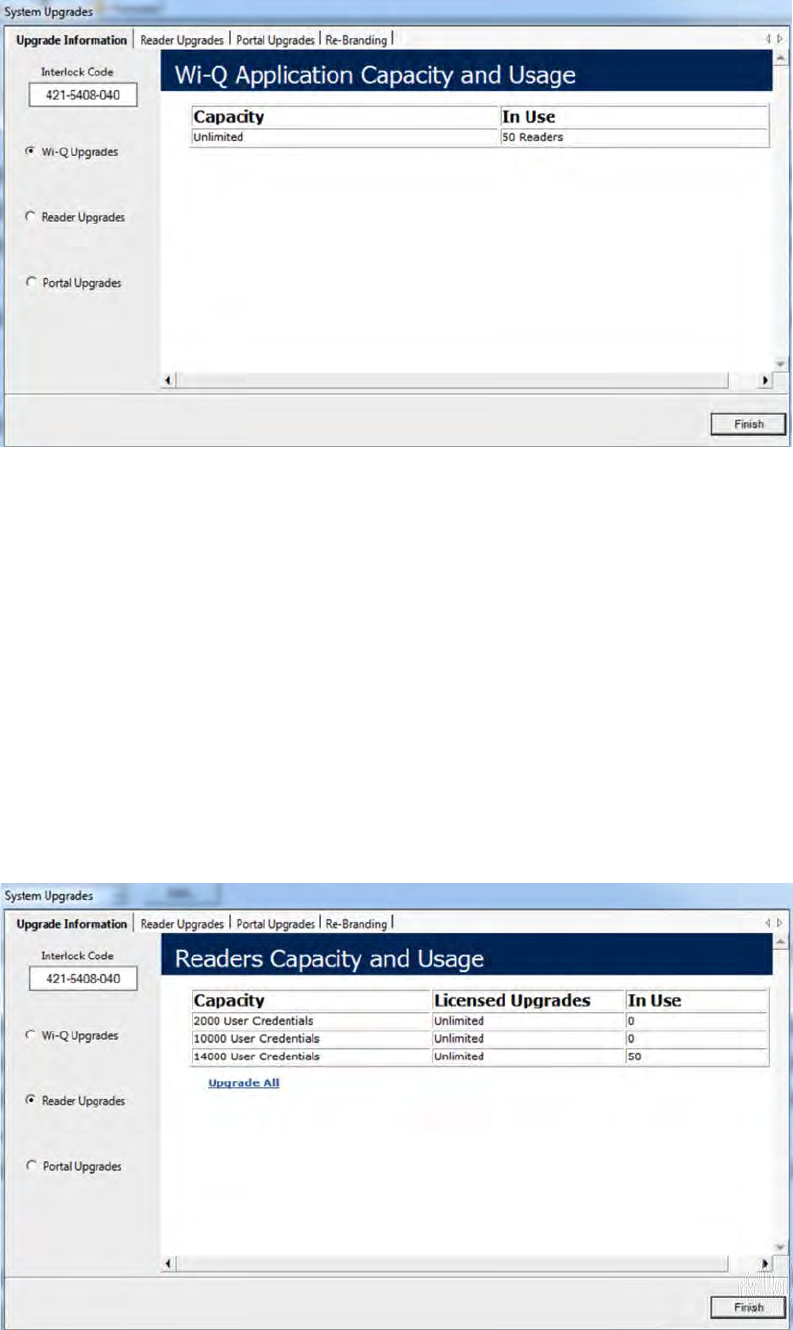
2 From the Wi-Q AMS Configurator File menu, select System Upgrades from the
dropdown list. The System Upgrades window opens at the Upgrade Informa-
tion Tab.
163
Figure 119 Upgrading your system capacity
AMS Upgrades
With the Wi-Q AMS Upgrades radio button selected on the left, the property
sheet displays the current reader capacity for the segment and how many of those
readers are currently in use.
Wi-Q AMS now offers free upgrades. All capacities can be set to unlimited with-
out a new interlock code.
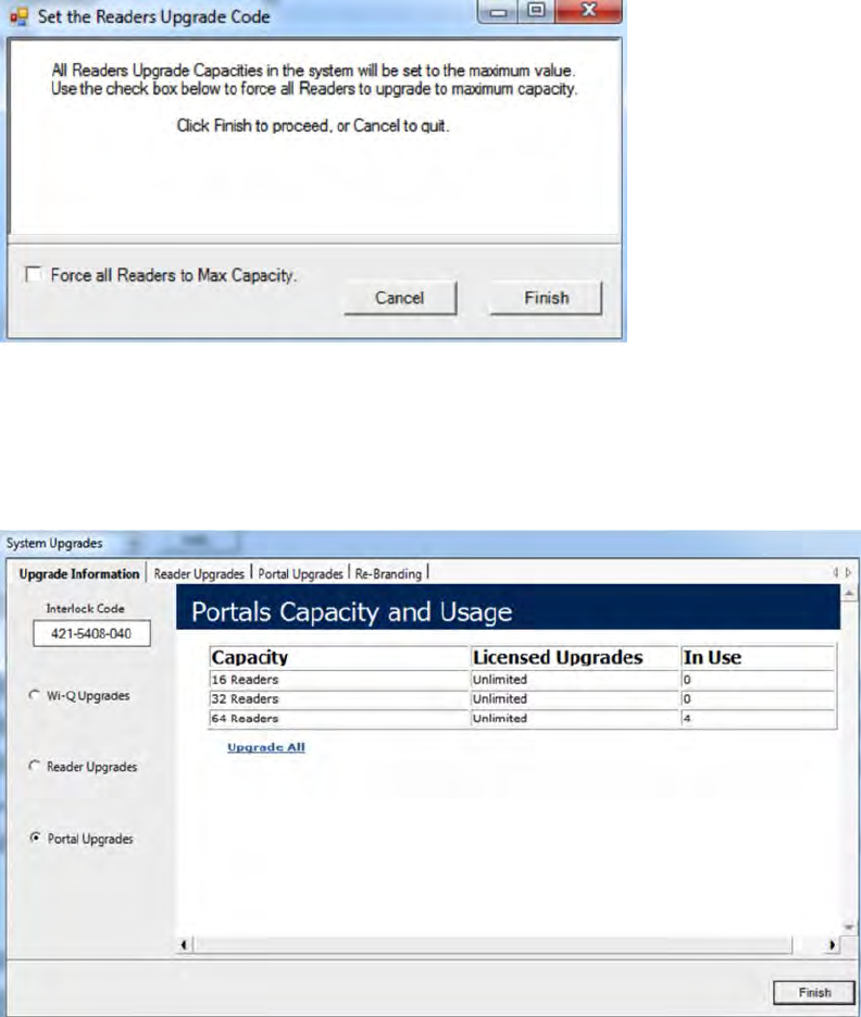
Reader Licenses in Use — With the Reader Upgrades radio button selected on
the left, the property sheet displays the number of Licensed Upgrades in each
user capacity value, and how many of those Licensed Upgrades are currently in
use.
164
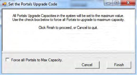
Select the upgrade all link if additional user capacity is needed.
Select force all readers to max capacity and click finish.
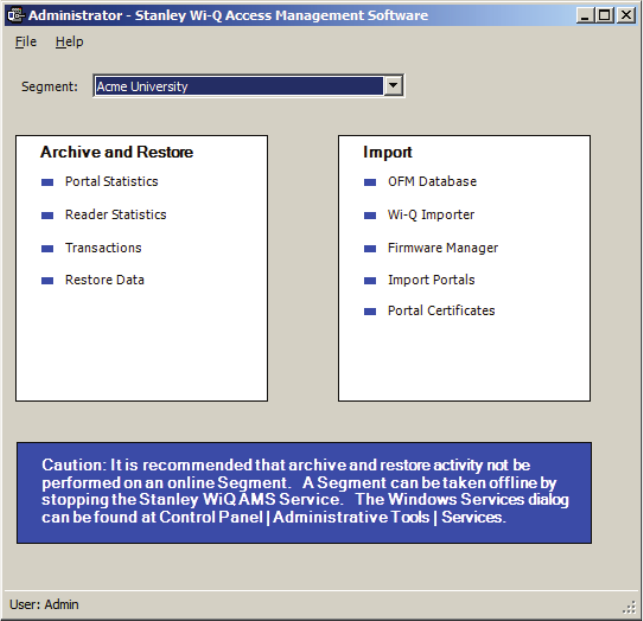
Portal Licenses in Use — With the Portal Upgrades radio button selected on the
left, the property sheet displays the number of Licensed Upgrades in each reader
capacity value, and how many of those Licensed Upgrades are currently in use.
165
Select the upgrade all link if additional reader capacity is needed.
Select force all portals to max capacity and click finish.
166
System Administrator
System Administrator is an application accessed inside Configurator or from the
Windows Start menu. With System Administrator, you can archive and restore
Portal statistics, reader statistics, and reader transactions. From here you can
also import data from an existing database or comma-delimited file. You must be
an AMS User with Administrator privileges to use this feature. It is a good idea
to archive records on a regular basis. It will be helpful to establish a protocol and
ensure that it is carried out according to plan.
Note Archiving and restoring transactions and statistics is not the same as performing a
full AMS database back up. Full back up and restore is performed using Microsoft
SQL Server Management Studio Express (installed with AMS). Complete steps are
described later in this chapter.
Establish an Archive Protocol
An industry best practice for use of any archiving systems is to establish a pro-
tocol for who, when and how much data to archive, depending on the volume and
nature of the data being archived. For security purposes, it will be important to
ensure the protocol is being implemented by also establishing an audit practice.
167
Using System Administrator
Figure 120 System Administrator
From here you can archive and restore statistics in the AMS database, import
data to AMS from the OFM Database, or import data from standard comma-delim-
ited files such as .txt and .csv.
Archiving Statistics in the AMS Database
It is important to maintain your database in optimum condition. On the basis of the
statistics volume in your segment, you should establish a protocol to regularly ar-
chive data that are not likely to be used again. For example, each month, you may
want to archive data that are three months old. When you archive records from
the software using the System Administrator application, the data is removed
from the database. The statistics can be fully restored to AMS in the future, if
necessary.
The archive feature operates the same for Portal statistics, Reader statistics,
and Transactions. The following steps illustrate how to archive Portal statistics;
however, the steps are the same for each type. You can archive statistics in all
devices or select a specific Portal or reader for archive.
Once you’ve selected the Portal or reader to archive, you can also select what
168
statistics to archive; for example, all statistics, only those statistics greater than a
specific ID, or specify a range of statistics older than a specific date.
To Archive Statistics
1 In the System Administrator application, select the segment for which you wish
to archive statistics.
2 In the main window, under Archive and Restore, select a Statistics type, such
as Portal Statistics.
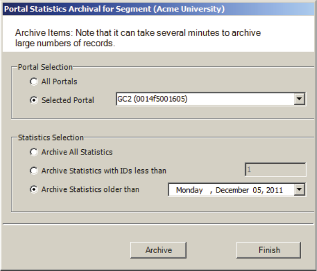
Figure 121 Portal Statistics Archival for Segment
3 In the Portal Selection box, select one of the following:
All Portals — All Portals’ data will be archived.
Selected Portal — Choose a Portal ID from the drop-down list. Data from only
that Portal will be archived.
169
4 In the Statistics Selection box, select one of the following:
Archive All Statistics — All statistics in the database will be archived.
Archive Statistics with IDs less than — Define an ID number. Only statistics
with IDs less than the defined number will be affected.
Archive Statistics older than — Select a date. Only data older than the date
selected will be archived.
5 When you have selected the appropriate options, click the Archive button and
click Yes if you wish to continue with the archive.
6 In the Windows browser, navigate to a folder or create a new one in which to
archive the file. You should create a filename that will be meaningful to your
segment (for example, all_Portals, or siteA_Portals). These files will be acces-
sible under this location should you wish to restore them at a later date.
7 Click OK. The system will display the status of the archive activity as it pro-
ceeds.
8 Click Finish to exit Portal Statistics Archive.
Restoring Data to the Database
You can restore data that have been archived by System Administrator back into
the database. Once this is done, you will be able to view them in Configurator and
its related applications.
To Restore Data to AMS
1 From the Configurator Segment Tab, select the segment for which you wish to
archive statistics.
2 From the Applications menu on the Configurator menu bar, select System Ad-
ministrator. The Systems Administrator window opens.
3 Select the Segment you wish to work with. From the left window pane, select
Restore Data. The Windows browser window opens.
4 Select the file you wish to restore to AMS, then click Open.
5 The system reports that the records will be restored to the Segment. Click
Yes to continue. The system will display the status of the archive activity as it
proceeds.
170
Importing Data from a Legacy OFM Database
You can import an entirely new segment into the software from a legacy OFM
database, or you can import all or some elements of data into an existing seg-
ment and overwrite any data with the latest data in the OFM. When you import an
entire segment from an OFM database, AMS creates a segment with the segment
name of the old database.
To Import Data to AMS
1 From the Applications menu on the Configurator menu bar, select System Ad-
ministrator. The System Administrator window opens.
2 From the right window pane, select OFM Database. The Windows browser
window opens.
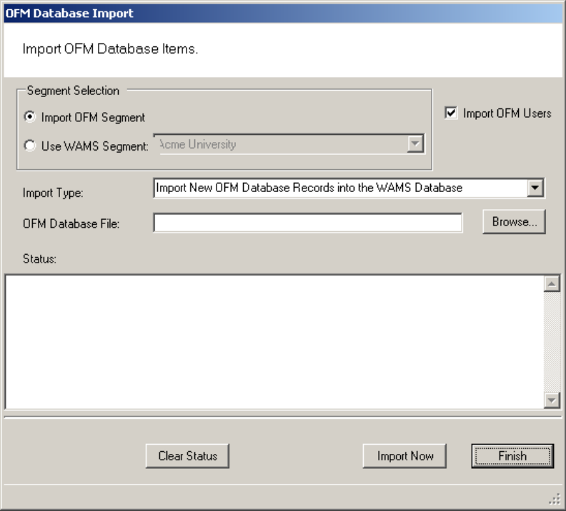
Figure 122 OFM Database Import
171
3 In the Segment Selection box, select one of the two options:
Import OFM Segment — This option imports a new segment in its entirety and
automatically gives it the name of the existing Segment in the OFM Database.
Use Segment — This option activates the drop-down list. Select the Segment
into which you wish to import data. It will import any new data and update any
existing records with the same ID based on the import type.
4 Select the Import OFM Users option if you want to include OFM Database ex-
isting Users and User Groups.
5 From the Import Type dropdown menu, select the type of import you wish to
perform:
Import New OFM Records into the Database — This will import only new re-
cords.
Merge New and Changed OFM Data into the Database — This will import all
data and add or update any records that are new since the last import.
6 Select Browse to find the OFM Database File.
7 Select Import Now. The data will begin to transfer and you will see the records
scroll through the Status window. This should take only a few minutes, depend-
ing on the size of the data being imported.
Import Data from a Standard Comma-Delimited File
You can also create a comma-delimited .txt or .csv file containing Names, Cre-
dentials and other AMS information and import the data directly to the database,
including any of the following data:
Last Name
First Name
Middle Initial
Proximity Card Credential
Proximity Card Type
Magnetic Stripe Card Credential
Keypad Credential
In addition, you can include data for any user fields created for the segment se-
lected for import.
AMS Importer imports files in a few easy steps:
Create the data file in the appropriate program, such as Microsoft Word, Excel,
172
or other text-based program and save it as a .txt or .csv format.
Prepare the Wi-Q AMS Import Utility to accept the file.
Import the data.
Send the Data to the database.
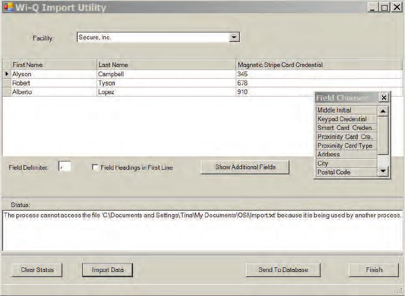
In the Import Utility, you can view the data as it imports into the window and
make any corrections to the file or column headers until you are satisfied with the
import before you actually send it to the database.
Detailed instructions are presented in the next few sections.
To prepare Wi-Q AMS Import Utility
1 From the Applications menu on the Configurator menu bar, select System Ad-
ministrator. The System Administrator window opens.
2 From the right window pane, select Wi-Q (or Omnilock) Importer. The Import
Utility opens.
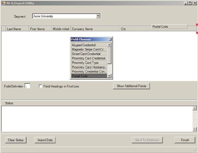
Figure 123 Import Utility
3 Use the cursor to drag the column headers into any order you wish.
173
4 If you wish to import additional data into user fields associated with the seg-
ment, click Show Additional Fields to display the Field Chooser and double-click
or drag to add them to the header.
5 Enter the appropriate Field Delimiter for the import file, the default is a comma.
6 If you have field headings in the first line of your data file, click the Field Head-
ing in First Line check box.
To import the data
1 Once all column headers are in the order you wish, click Import Data.
2 Navigate to the location of the data file you created and click Open.
3 The Data appears under the appropriate column headers in the upper window.
If the file is large, you can watch the progress in the Status box on the bottom
of the window.
Figure 124 Using the Import Utility
174
4 Review the data import. Scroll the window to ensure the data has imported in
the appropriate column headers. If not, you can rearrange the column headers
and import the file again. You can do this as many times as you need to ensure
you will get a good import.
5 Once you are satisfied that the data has imported as intended, click Send to
Database. The data will now appear in the appropriate fields throughout AMS.
Backing Up and Restoring Your AMS Database
Full backup and restore functions are performed outside of AMS using Microsoft
SQL Server Management Studio Express (installed with the software). You should
plan to perform this function on a regular basis. You can also use this program to
move the database to a different computer.
WARNING: This operation should be performed only by an IT professional who is
designated as an AMS User with Admin or Programmer privileges.
Backing Up the Database
Perform the following steps to back up the database.
1 Exit AMS.
2 From the Windows Start menu, select Programs>Microsoft SQL Server Man-
agement Studio Express. The connect to Server dialog box opens.
3 Enter the Server type, Server name, and choose your Authentication type.
Then, click Connect.
175
4 The program opens at the default database location.
Figure 125 Default database display in SQL Server
5 Double-click on databases, then right-click on the folder and select
tasks>Backup. The backup database dialog box opens.
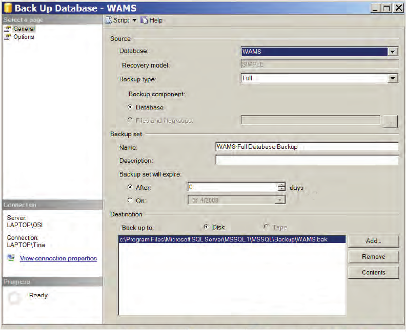
176
Figure 126 Backup Database
6 Define a Backup Type (full or differential) and add a description of the backup
(optional).
7 The default destination displays. You can change the destination, if needed,
for example if you wish to move the database to a new location on a different
computer.
8 Click OK. The backup progresses and the system reports when the backup is
complete.
To Restore the database
1 Exit AMS.
2 From the Windows Start menu, select Programs>Microsoft SQL Server Man-
agement Studio Express. The connect to Server dialog box opens.
3 Enter the Server type, Server name, and choose your Authentication type.
Then, click Connect.
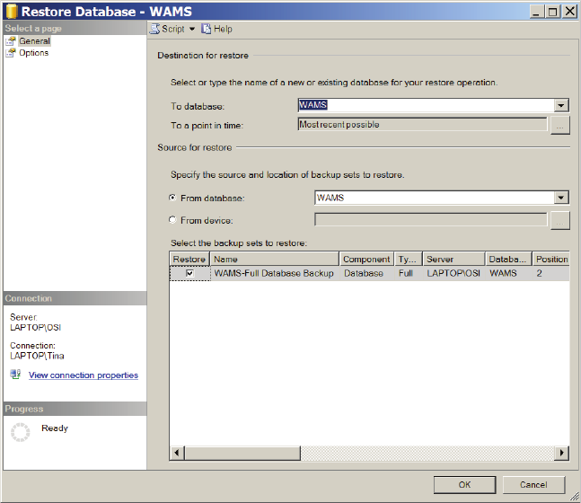
177
4 The program opens at the database location.
5 Double-click on databases, then right-click on the folder and select
tasks>Restore>database. The restore database dialog box opens.
Figure 127 Restore Database
6 The location defaults to the original location. You can specify a different loca-
tion, for example, if you wish to more the database to a different computer.
7 Specify the source from which to restore and select a backup set to restore.
8 Select the backup set you wish to restore from the available list.
9 Click OK. The restore progresses and the system reports when the restore is
complete.
178
Firmware Updates
Firmware updates will be sent to you periodically by Stanley Technical Support.
You can upload these firmware files to your database by using the System Admin-
istrator Application, and then you can send the updates to your hardware from
the Configurator’s Firmware Tab. This section will guide you through the firmware
update process.
Firmware File Types
Every Controller has two firmware files:
Application File: Software that provides the access control decision-making
functionality on a Controller
Bootloader File: Software that executes the reprogramming session on the
Controller
The application file is what is typically reprogrammed by the Stanley Team, but it
is possible that the bootloader file will require reprogramming as well. Controller
firmware files will always have a “binhe” file extension.
For Portal Gateways, only one file is required for reprogramming, and the file
name begins with the version number and ends with “image.bin.gzhe.”
Uploading Firmware Files
1 In the System Administrator application, choose Firmware Manager from the
Import list on the right. The Manage Firmware Files dialog box opens.
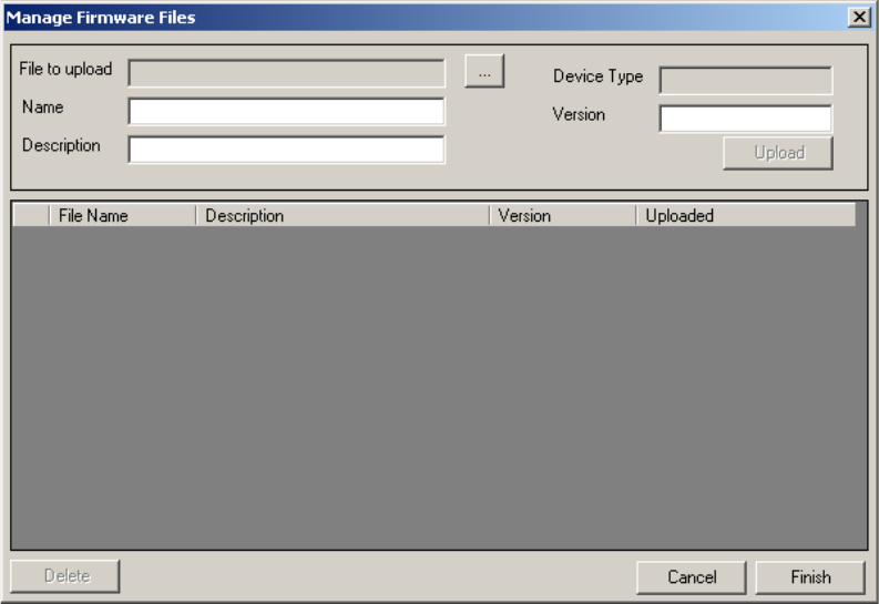
179
Figure 128 Manage Firmware Files
2 Click on the ellipsis button next to the File to upload field. Browse to your Portal
gateway or Controller file(s). Once you’ve located your file, click Open.
3 Provide a unique name and description of the firmware file. If you are upload-
ing a Controller firmware file, it is recommended that you build either “Boot” or
“Application” into your description name, depending on the file type.
4 Click Upload. The firmware file will be added to the list at the bottom of the
screen and added to your database.
To avoid confusion between updates, it is recommended that you only keep the
latest firmware files in your list. To remove older files, select the file(s) you wish to
delete and click on Delete.
5 Click Finish once all of your files are uploaded.
You are now ready to send the updates to your hardware.
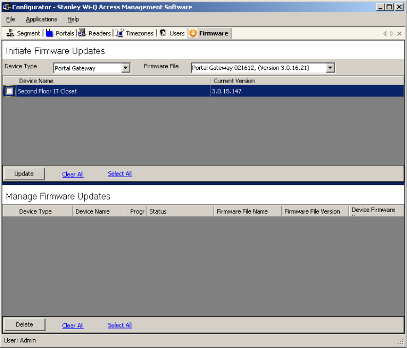
180
Firmware Reprogram
Perform the following steps to send firmware updates to your hardware.
1 If not already open, launch the Configurator application and click on the Firm-
ware tab.
Figure 129 Configurator Firmware Tab
2 Choose your device type from the dropdown menu, and choose the appropriate
firmware file.
Note If you are reprogramming both the Bootloader and Application files on a Controller,
you must update the Bootloader file first.
3 Check the boxes next to the devices that need updating. You can click Select
All or Clear All as needed.
4 Once you’ve made your selections, press Update.
5 The devices will be added to the Manage Firmware Updates queue below,
where you can view the download progress and status.
181
Transactions Monitor
Each time a user accesses the system, the software collects a transaction from
the Controller/Portal Gateway network. Once the system is signed on and users
begin accessing the system, transactions begin including any alarm activity. You
can monitor all this activity in Transactions. Access Transactions via the Windows
Start menu.
To Launch Transactions
1 Select Start>All Programs> Stanley Security Solutions >Stanley Wi-Q AMS>
Transactions.
2 Enter your Login and Password. Transactions opens at the Transactions Tab.
3 From here you can view all transaction and alarm activity for the segment you
select.
Note: If you have been assigned the Manager or Administrator User Type, you can
launch Transactions from the Applications menu in Configurator.
Transactions Overview
As activity takes place throughout the segment, AMS tracks each event as a
transaction. The most obvious use of Transactions is to recognize and investigate
when security has been compromised. You can immediately locate the source of
an alarm and take the action necessary to respond according to your segment
policy and procedure.
AMS gives each transaction in the database a unique ID, records the time and
type of transaction, the Controller where the transaction occurred and the User ID
and Group name associated with the transaction. You can monitor all this activity,
real time, from the Transactions application. The transactions can be organized
and sorted according to how you want to use the data. In addition, you can tempo-
rarily pause data updating if you need to review a transaction in more detail.
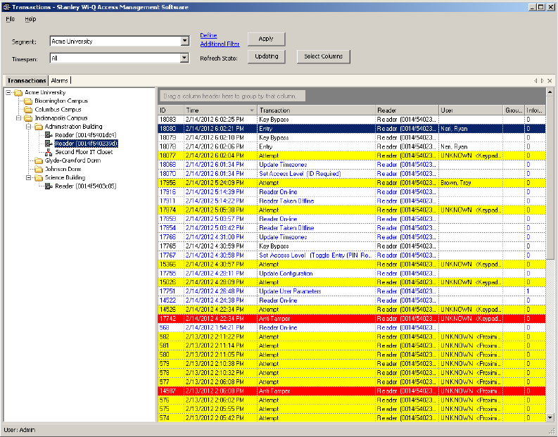
182
Transactions Tab
You can view all transactions as they occur in the Transactions Tab. Alarm trans-
actions such as Forced Entry or Anti Tamper display in red. Access requests
“attempted but not allowed” displays in yellow. Successful access requests
display in black on a white background.
Figure 130 Transactions
System transactions such as changing an access level or clearing an alarm dis-
play in blue on a white background. To review and respond to alarms, select the
Alarms Tab.
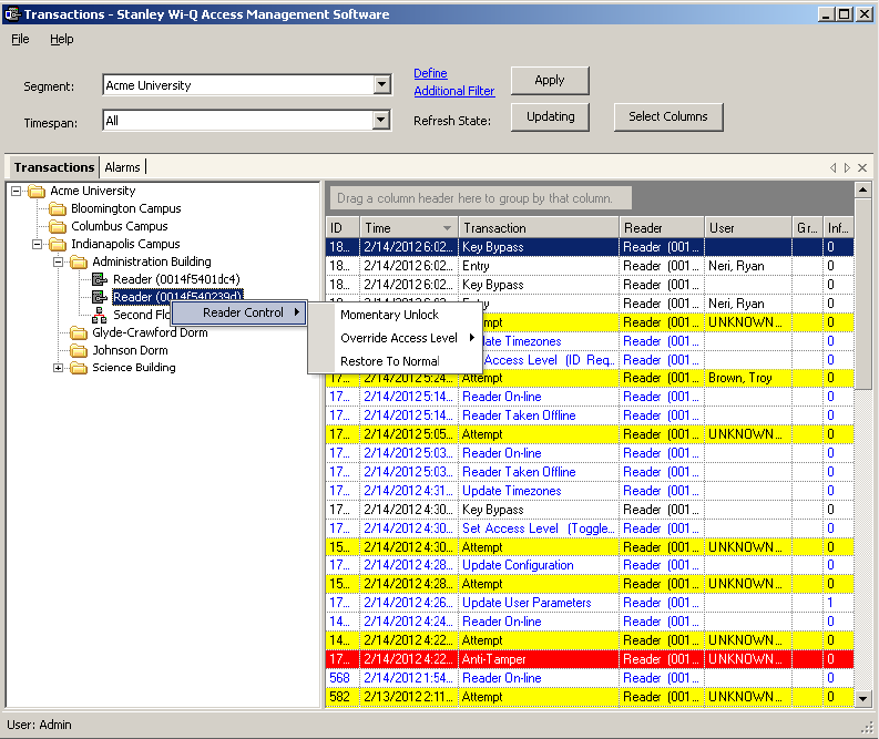
183
Reader and Portal Controls
You can access reader and Portal controls from inside the Transactions tab. From
here you can override access levels of readers to unlock or lockout one or a whole
related group of readers. To use this feature, simply right click on the Portal or
reader and select an option.
Figure 131 Accessing Portals and Readers in the Transactions tab
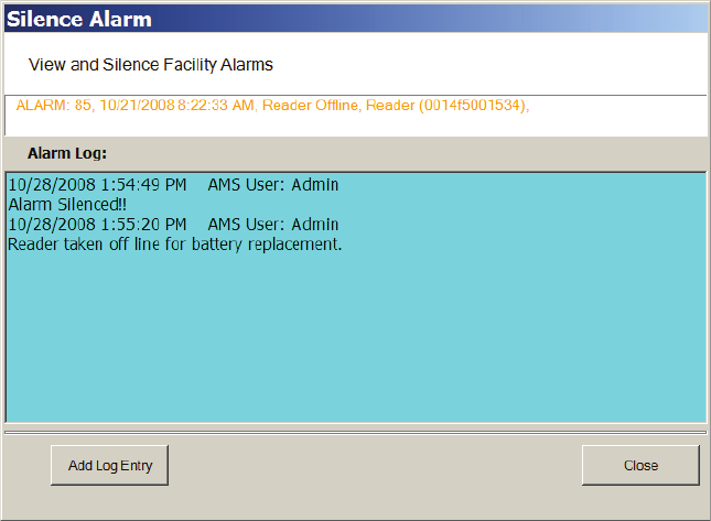
184
Alarms Tab
When an alarm is triggered, such as a door is blocked open or forced entry, the
system creates an alarm record. When you select the Alarms tab, unanswered
alarms display in red and activate an alarm sound .wav file on your computers
sound system.
When you “silence” an alarm in Transactions, you are simply telling the system
that you have recognized the alarm condition. The alarm sound .wav file will stop
on your computer system for that alarm and the display color changes from red to
yellow. A log will be generated recording the time and date the alarm was si-
lenced. You can add a comment to this log to further define the incident
Figure 132 Silencing an alarm in the Alarms tab
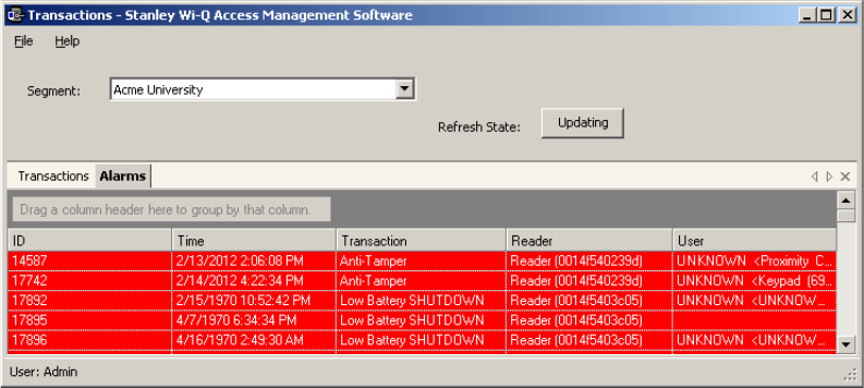
185
Create an Alarm Response Protocol
Remember, when you “Silence” an alarm in Wi-Q AMS Transactions, you are only si-
lencing a .wav file; you are not resolving the problem. It is important to establish Alarm
Response protocols within your segment and follow up with action. See “Responding
to Alarms” on page 188.
Figure 133 Alarms Tab
Transaction Types
The database records transactions by category. Under normal operating condi-
tions, the most common transaction types will be Entry and Request to Exit. The
system recognizes various alarm and status categories, such as:
Alarm Cleared (All)
Alarm Cleared (Forced Entry)
Anti-Tamper
Organizing and Sorting Transactions
AMS makes it easy to manage high transaction traffic. You could view every
transaction in the system, real time. However, in large systems where hundreds
of transactions can occur in a very short time, you may want to limit the number of
transactions displayed, or group them in a way that makes sense for system activ-
ity. For example, you can limit the transactions list to only those that occurred in
the last ten minute timespan; you can sort ascending or descending by column
header; and you can arrange the columns in any order you wish. In addition, you
can create a hierarchy, rather than a columnar view.
Display by Timespan
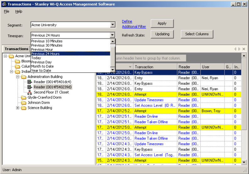
186
By default, Transactions displays all transactions in the order they occur. If you
are monitoring all transactions, you may want to simply watch them as they occur.
However, in large systems, your effort may best be served by limiting transactions
to only those that have occurred in the previous ten minutes, or previous hour. The
software gives you a number of options from All to year to date.
To set the display timespan
In the Transactions Tab, select the Segment you wish to monitor.
Under Timespan, select the timespan you wish to display from the drop-down list.
The display list on the right changes to reflect your selection.
Figure 134 Transactions Timespan
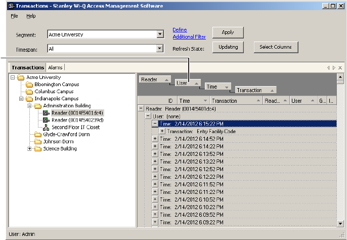
187
Sort by Column Header
You can sort Transactions by column header in ascending or descending order.
This is helpful, depending on what you are looking for. If you simply want to watch
transactions in the order they occur, the default setting—sorted by ID, descend-
ing—will display the most recent transaction on the top line of the list. However,
if you have an interest in viewing all the activity of a particular user, you can sort
alphabetically by User credential. As with common database programs, you can
move the columns in the column header to any order you wish. Transactions will
remember your changes and display in the new order when you next open the
program.
View Transactions in Tree Levels
You can display transactions similar to the way you view the Segment Tree in
Configurator. This is useful to minimize and organize the amount of data you view
at one time.
Figure 135 Transactions in Tree Levels
In this example, we placed Readers at the top of the tree; however, you can place
them in any hierarchy you wish. When you select the plus sign next to the top
level, the second and third level items expand to display. It’s easy to create a
Transactions Tree: simply drag and drop the column headers into position.
Transaction Filters
If you want to search for a specific transaction by certain criteria (user name,
Drag column
headers to
gray area.
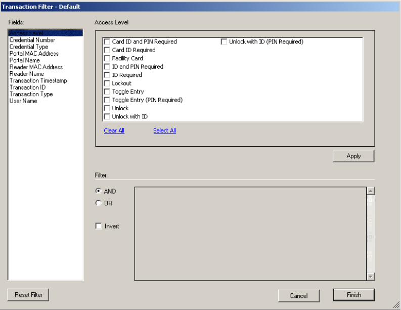
188
reader name, etc.), click on Define Additional Filter at the top of the Transactions
module. The Transaction Filter dialog box will open.
Figure 136 Transaction Filters
A list of fields is located on the left side of the dialog box. Clicking on a field will
bring up checkbox or dropdown options specific to the selected field. In Figure
141, the Access Level field is selected. Here, you can check multiple options. Once
you’ve selected your options, click Apply. The Filter section at the bottom of the
dialog box will reflect what filter you’ve applied.
You can turn on multiple filters with the use of the AND/OR selection options in
the Filter section. If you’d like to search your transactions by a specific access
level and reader name, apply both filters and select AND.
If you want to omit certain transactions from your list, you can click the Invert
checkbox once you’ve applied your filters. Inverting will adjust your list so that the
applied filters are not shown.
When finished creating filters, click Finish. If you would like to clear your filters,
click on Reset Filter.
Responding to Alarms
189
When an alarm occurs, the system immediately displays it in red in the Transac-
tions Tab. The alarm will be categorized as either an Anti-Tamper or a Forced
Entry type. At this point, you will take action according to your segment’s security
plan. In a small segment, you may simply dispatch a person to physically investi-
gate the source of the alarm. In larger facilities with I/O devices in the system, the
alarm may trigger a video recorder, a lighting plan, or other I/O device. In either
case, you will respond to the alarm in Transactions using the Alarms Tab.
As with the Transactions Tab, you can sort the alarms in ascending and descend-
ing order with a column, and change the order in which the columns display, and
create an Alarms Tree.
To respond to and silence an alarm
1 Select the Alarms Tab.
2 Double-click on an active alarm (displaying in red). The Silence Alarm text box
opens. Alarm details display in red text in the message area.
3 Click on Silence Alarm.
4 To add a log entry, click Add Log Entry.
5 Enter a comment in the text box.
6 When finished, click Add to Log.
7 The message entered will become the record for the alarm event.
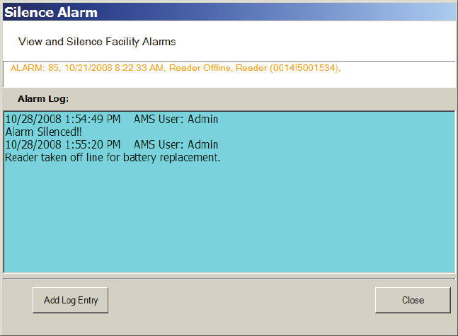
190
Figure 137 Log Entry Recorded
8 Select Close. In the Alarms Tab, the alarm line changes from red to yellow and
the alarm sound stops.
9 You can continue to add comments in the alarm’s log until the condition is
resolved.
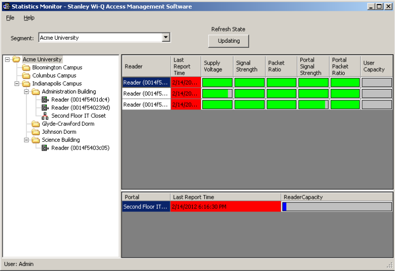
191
Statistics Monitor
The Statistics Monitor is a powerful tool that displays a real-time, color coded
overview of system performance. When you set up your new system, and want
to monitor ongoing system performance, you will use the Statistics Monitor.
This tool appears similar to the Configurator, displaying the Segment Tree for the
segment you select on the left of the screen, and the hardware categories on the
right. To check the performance of the entire system, select the segment at the
top of the tree. Reader statistics display at the top of the screen and Portal statis-
tics display at the bottom.
You can access the Statistics Monitor from the Applications menu at the top of
the Configurator Main Screen or launch it from the Windows Start menu as a
separate application
Reader Statistics
Figure 138 Viewing Reader Statistics
In this example, the system is performing well, delivering transactions at an ac-
ceptable level. To display the actual measurement, hover the cursor over a bar.
To get more detail; for example, to diagnose the problem of low signal for a partic-
ular reader, you can navigate to that reader in the Segment Tree and see data for
only that reader. You can also double-click the reader on the right panel. Specific
information for the selected reader displays in the list on the right.
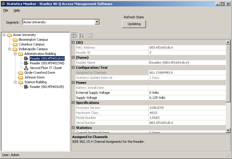
192
Figure 139 Display reader detail
Here, you can see the reader’s MAC Address, ID, Reader Name, and the Portal as-
sociated with it. You can also view the reader’s power performance.
Automatic Updates
The Updating button can be used to pause automatic updating to view a snap shot
of data. This is especially useful when viewing the top level, where the values may
be changing rapidly.
Configuration/Test
Under the Configuration/Test category inside a reader’s property list, you can see
the Statistics Update Interval. This value can be changed in the Readers tab of the
Configurator application. For more information on configuring readers, see Chap-
ter 4, “Configuring Segments, Portal Gateways and Controllers”.
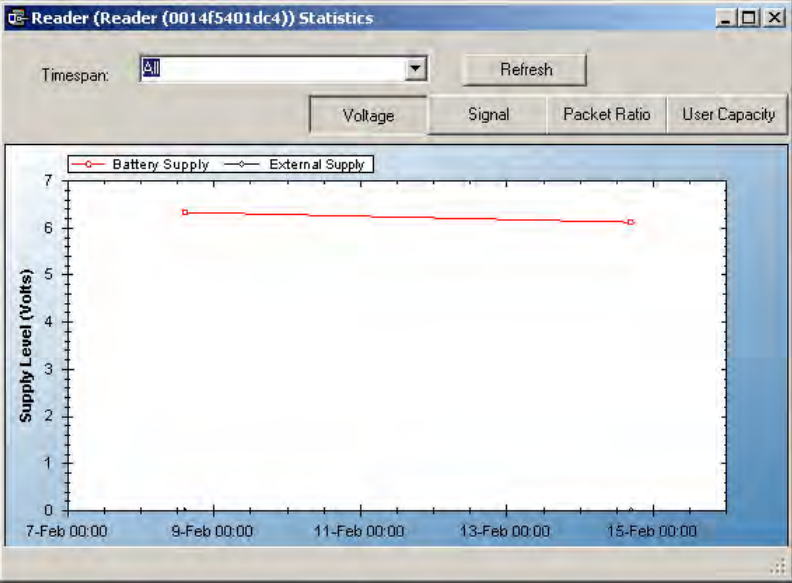
193
Power
To view individual reader performance:
1 Under the Power Category, place the cursor in the field next to Supply Voltage,
and select the ellipsis button.
2 The Reader Statistics chart opens at the Voltage Tab. From here you can also
check the Signal, Packet Ratio, and User Capacity.
Voltage Tab
The Voltage Tab displays battery and external power supply to ensure battery
integrity and longevity. If you see a downward trend, you should consider replac-
ing the battery for preventive maintenance.
Figure 140 Reader Statistics Voltage Tab
Every minute, the reader sends a beacon to the Portal Gateway with signal
strength, battery voltage, external supply voltage and packet transfer ratio infor-
mation. These statistics are stored at the rate defined by the Statistics Update
Interval.
Select Refresh to get the latest readings, or you can reset the timespan to various
intervals relevant to your diagnostic evaluation. You can move through the tabs as
you check the system performance.
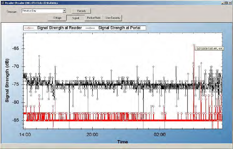
194
Signal Tab
The Signal Tab displays the signal strength at the reader and at the reader’s Por-
tal.
Figure 141 Reader Statistics Signal Tab
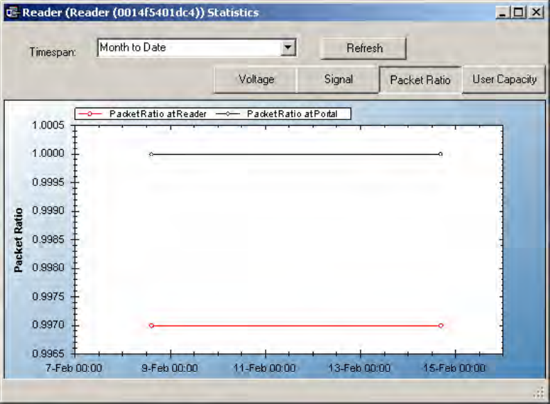
195
Packet Ratio Tab
The Packet Transfer Ratio at Reader is the number of valid packets received ver-
sus the total number of packets sent to the reader. The Packet Transfer Ratio at
Portal is the number of valid packets sent from the reader versus the total number
of packets received at the Portal. If the Packet Ratio is high (near 1, or 100%) your
readers are performing well, even though signal strength might be low. If signal
strength is high and Packet Ratio is low, you may have a problem at the reader, or
there may be interference on the channel that the Portal is using.
Figure 142 Reader Statistics Packet Radio Tab
User Capacity
This chart shows the Max allowable users for this reader and the current use. If
you find that the use is nearing capacity, you may want to consider upgrading the
reader capacity. See “Segment Item Upgrades” on page 162.
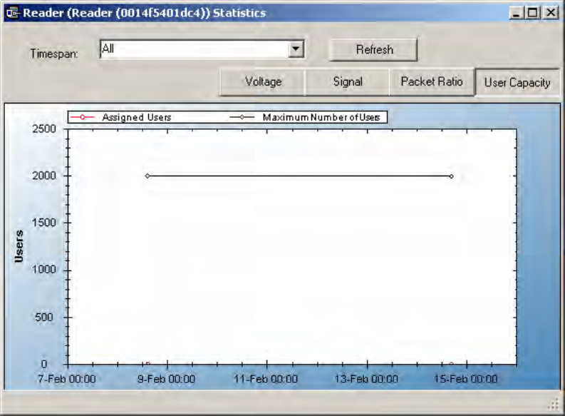
196
Figure 143 Reader Statistics User Capacity Tab
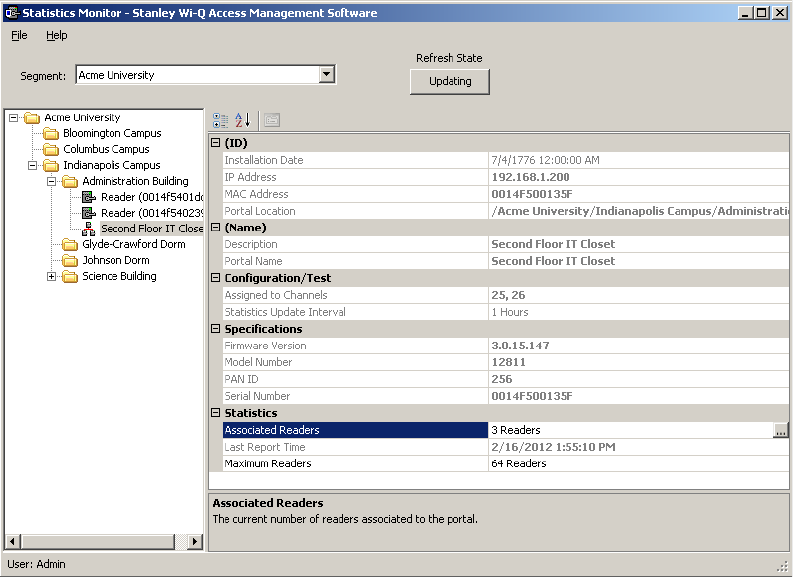
197
Portal Statistics
Portal Statistics display at the bottom of the Statistics Monitor. Select the top
level in the Segment Tree to display all Portals in the system. See Figure 143.
Clicking on a Portal within the Segment Tree in the Statistics Monitor will display
the Portal’s properties on the right.
Figure 144 Statistics Monitor Portal Properties
The Portal ID, Name, Specifications such as Firmware Version, Model Number,
PAN ID, and Serial Number display on the right. In the Statistics category, you can
see how many readers are associated with the Portal and its current maximum
reader capacity.
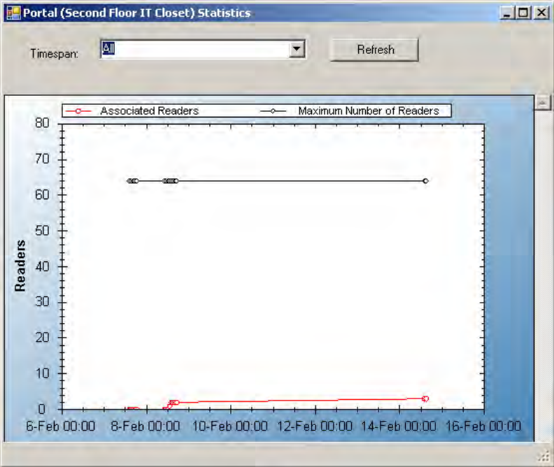
198
Portal Diagnostics
You can check the reader counts associated with a Portal over time for a detailed
look at Portal capacity. This is useful to determine if some readers are operating
intermittently or dropping out of range at intervals.
To review associated readers at Portals
1 In the Portal detail display, Statistics Category, place the cursor in the
Maximum number of Readers field and select the ellipsis button. The Portal
statistics chart opens for the Portal selected.
Figure 145 Portal Statistics
If the Associated Readers line appears steady and reflects the number of read-
ers you know are associated with the Portal, your readers are consistently being
recognized by the Portal. If this line is erratic; for example, showing a drop or
fluctuation on associated readers over time, you may want to review the readers
to see if there is a problem with power supply or signal that is making one or more
of them drop out of range.
Configuration/Test
199
In the Configuration/Test category, the Statistic Update Interval is visible. You can
modify this value in the Configurator application’s Portals Tab.
Reports
You can view a wide variety of reports based on data collected in Configurator
and Transactions. You can access Reports from the Applications menu at the top
of the Configurator Main Screen or launch it as a separate application.
To Launch Wi-Q AMS Reports
1 Select Start>All Programs> Stanley Security Solutions >Stanley Wi-Q AMS>
Wi-Q Reports.
2 Enter your Login and Password. Reports opens.
Reports Overview
The software provides seven reports that you can modify:
Users of Readers — Generate a report that lists all readers and the users cur-
rently assigned to them, or you can specify a particular reader and view only the
users for that reader.
Users of Groups — Generate a report that lists all user groups and the users cur-
rently assigned to them, or you can specify a particular user group and view only
the users for that group.
Users Entry Log — Generate a report that lists user entry data for all users and all
readers, or you can specify which readers and users to list. You can also specify a
timespan or Begin and End dates on which to report.
Users Entry/Exit Log — Generate a report that lists user entry/exit data for all
users and all readers, or you can specify which readers and users to list. You can
also specify a timespan or Begin and End dates on which to report.
Alarms Log — Generate a report by alarm for all readers in all timespans, or
specify which alarms, timespans, or Begin and End dates.
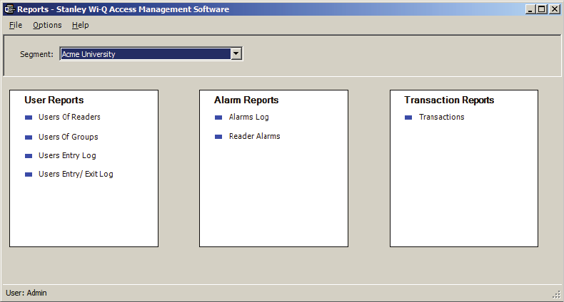
200
Reader Alarms — Generates a report by reader for all alarms in all timespans, or
specify which readers, timespans, or Begin and End dates.
Transactions — Generate a report for all transactions at all readers for all users
during all timespans, or specify which transactions you wish to list.
Creating Reports
The first step in creating reports in the software is to configure report settings.
Here you can enter your company name and include a picture or logo that will be
included in any files exported or printed from the application. Once you have con-
figured your report settings you are ready to choose a report type and generate
the report. From there you can print the report, or export the report to any number
of file formats such as .doc, .rtf, .rpt, etc.
To get started, launch Reports from the Configurator main menu.
Once you enter your login and password, the Reports main screen opens.
Figure 146 Reports