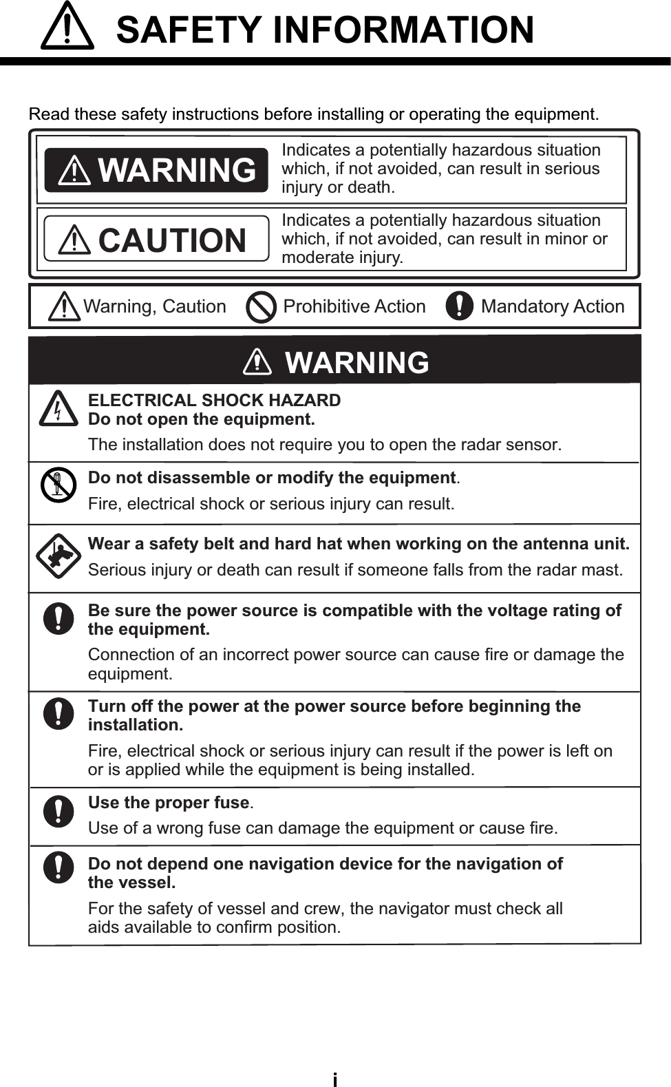
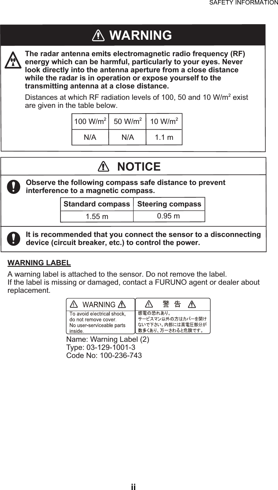
Furuno USA 9ZWRTR104 Transceiver for Radar Sensor DRS4DL User Manual

Furuno USA Inc Transceiver for Radar Sensor DRS4DL

User Manual I

www.furuno.comAll brand and product names are trademarks, registered trademarks or service marks of their respective holders.Installation ManualRADAR SENSORMODEL DRS4DLSAFETY INFORMATION.................................................................................................. iSYSTEM CONFIGURATION .......................................................................................... iiiEQUIPMENT LIST .......................................................................................................... iv1. INSTALLATION.......................................................................................................... 11.1 Installation Considerations....................................................................................................11.2 Installation of the Radar Sensor............................................................................................22. WIRING....................................................................................................................... 62.1 Power Requirement ..............................................................................................................62.2 Check Points After Installation ..............................................................................................63. MAINTENANCE, TROUBLE- SHOOTING................................................................. 83.1 Maintenance .........................................................................................................................83.2 Replacement of Fuse............................................................................................................83.3 Troubleshooting ....................................................................................................................93.4 Replacement of Magnetron...................................................................................................9PACKING LIST............................................................................................................ A-1OUTLINE DRAWING................................................................................................... D-1INTERCONNECTION DIAGRAM ................................................................................ S-1
The paper used in this manualis elemental chlorine free.・FURUNO Authorized Distributor/Dealer9-52 Ashihara-cho,Nishinomiya, 662-8580, JAPANA:0000Printed in JapanAll rights reserved.Z1:JAN.30, 2015Pub. No.IME-36370-Z1(TASU)DRS4DL 0 0 0 1 6 5 8 2 8 1 0
i SAFETY INFORMATION  Read these safety instructions before installing or operating the equipment.WARNINGIndicates a potentially hazardous situation which, if not avoided, can result in minor or moderate injury. Warning, Caution Prohibitive ActionCAUTION Mandatory ActionIndicates a potentially hazardous situation which, if not avoided, can result in serious injury or death. Wear a safety belt and hard hat when working on the antenna unit.Serious injury or death can result if someone falls from the radar mast.ELECTRICAL SHOCK HAZARDDo not open the equipment.The installation does not require you to open the radar sensor.Be sure the power source is compatible with the voltage rating of the equipment.Connection of an incorrect power source can cause fire or damage the equipment.Turn off the power at the power source before beginning the installation.Fire, electrical shock or serious injury can result if the power is left on or is applied while the equipment is being installed.WARNINGDo not disassemble or modify the equipment.Fire, electrical shock or serious injury can result.Use the proper fuse.Use of a wrong fuse can damage the equipment or cause fire.Do not depend one navigation device for the navigation of the vessel.For the safety of vessel and crew, the navigator must check all aids available to confirm position.
SAFETY INFORMATIONiiWARNINGThe radar antenna emits electromagnetic radio frequency (RF) energy which can be harmful, particularly to your eyes. Never look directly into the antenna aperture from a close distance while the radar is in operation or expose yourself to the transmitting antenna at a close distance.Distances at which RF radiation levels of 100, 50 and 10 W/m2 exist are given in the table below.100 W/m210 W/m250 W/m2N/A N/A 1.1 mWARNING LABELA warning label is attached to the sensor. Do not remove the label.If the label is missing or damaged, contact a FURUNO agent or dealer about replacement.Name: Warning Label (2)Type: 03-129-1001-3Code No: 100-236-743NOTICEObserve the following compass safe distance to prevent interference to a magnetic compass.It is recommended that you connect the sensor to a disconnecting device (circuit breaker, etc.) to control the power.Standard compass Steering compass1.55 m 0.95 m
iiiSYSTEM CONFIGURATIONPower supply12/24 VDC RADAR SENSORDRS4DLMulti Function DisplayTZTL12F/TZTL15F* TZT9/TZT14/TZTBBLANPre-attached power/LAN cable 1 m: Standard Supply* Software upgrade is required.Selectable power/LAN cableCP03-36400/CP03-36410/CP03-36420/CP03-36430(10/15/20/30 m)
ivEQUIPMENT LISTStandard supplyOptional supplyName Type Code No. Qty RemarksRadar Sensor RSB-127-104 000-027-200-00 1Installation Materials CP03-35701 001-265-920-00 1CP03-36400 000-027-211-00 1 Power/LAN cable 10 mCP03-36410 000-027-212-00 1 Power/LAN cable 15 mCP03-36420 000-027-213-00 1 Power/LAN cable 20 mCP03-36430 000-027-214-00 1 Power/LAN cable 30 mSpare Parts SP03-17901 001-351-470-00 1Documents IME-36370-* 000-165-828-10 1MDC-36370-* 000-165-829-10 1E32-01314-* 000-178-948-10 1Name Type Code No. Qty RemarksRadome Mount OP03-209 001-078-350-00 1
11. INSTALLATION1.1 Installation ConsiderationsGeneral considerations•  The radar sensor has no power switch. Therefore, it is recommended that you con-nect the sensor to a distribution switchboard with a switch for power control.Sensor placement•  Install the radar sensor on the hardtop, radar arch or on a mast on an appropriate platform. (For sailboats, a “radome mount” is optionally available for fixing the sen-sor to a mast.) Place the sensor where there is a good all-round view with, as far as possible, no part of the ship’s superstructure or rigging intercepting the scanning beam. Any obstruction will cause shadow and blind sectors. A mast for instance, with a diameter considerably less than the horizontal beam width of the radiator, will cause only a small blind sector, but a horizontal spreader or cross trees in the same horizontal plane as the radar sensor would be a much more serious obstruction; you would need to place the radar sensor well above or below it. Be sure there are no metallic objects near the antenna. See illustrations below for typical placement on a sailboat and powerboat.NOTICEDo not apply paint, anti-corrosive sealant or contact spray to coating or plastic parts of the equipment. Those items contain organic solvents that can damage coating and plastic parts, especially plastic connectors.Installation on a sailboat Installation on a powerboatTypical installation on a sailboat and power boatRadar sensorRadar sensorRadar sensorRadar sensorRadar sensorRadar sensorRear View(Rear View)(Rear View)Horizontal Beam Width12.5°12.5°
1.  INSTALLATION2•  It is rarely possible to place the radar sensor where a completely clear view in all directions is available. Thus, you should determine the angular width and relative bearing of any shadow sectors for their influence on the radar at the first opportunity after fitting.•  In order to reduce the chance of picking up electrical interference, avoid where pos-sible routing the power cable near other electrical equipment on-board. Also, avoid running the cable in parallel with other power cables.•  Select a location that does not allow water to accumulate at the base of the sensor.•  A magnetic compass will be affected if the radar sensor is too close to the compass. Observe the compass safe distances mentioned in the SAFETY INSTRUCTIONS to prevent interference to a magnetic compass.•  Do not paint the radome to ensure proper emission of the radar waves.•  When this radar sensor is to be installed on large vessels, consider the following points:•  The length of the standard supply power/LAN cable 1 m (from radome to the con-nector).•  The power/LAN cable runs between the radar sensor and display and comes in lengths of 10 m, 15 m, 20 m or 30 m. Select the length when purchasing.•  Deposits and fumes from a funnel or other exhaust vent can adversely affect the aerial performance and hot gases may distort the radiator portion. The radar sen-sor must not be mounted where the temperature is more than 55°C (131°F).1.2 Installation of the Radar SensorPrepare a wrench for M10 bolts for installation. Determine the suitability of the mount-ing location BEFORE permanently mounting the sensor. Incoming and outgoing sig-nals may overlap one another depending on the shape of the vessel, preventing communication between the radar and display. Set the sensor on the selected location and connect the sensor to the distribution switchboard and display unit. Turn on the sensor and the display unit. Check that the picture is updated with each sweep on the display unit. Some trial and error may be necessary to find a suitable location.Required tools for installationPrepare below tool before installation of radar sensor.•  A wrench for M10 bolts• A drill with 11 mm (0.43”) drill bit
1.  INSTALLATION3Installation on a platformInstallation of radar sensor to a platform is as shown below. Read below for the steps and details.1. Remove four each of hex bolts (M1020), flat washers and spring washers pre-attached to the bottom of the radar sensor.2. Construct a platform, cut four holes in the platform referring to the outline drawing and the mounting template at the back of this manual. Fasten the platform to the mounting location. The holes of the platform must be parallel with the fore and aft line.3. Put the radar sensor on the platform with the bow mark () on the sensor aligned with the ship’s bow.4. Use hex bolts*, flat washers and spring washers (removed at the first step) to at-tach the radar sensor to the platform. The torque for the bolts is 19.6 to 24.5 N•m. Apply marine sealant to the bolts.STERN BOWAlign bow mark (Δ) on radome with ship’s bow.Power/LAN cable (1 m)Drill holes referring to the outline drawing and the mounting templatePlatformHex bolt (M10×20)Spring washerFlat washerHex bolt (M10×20)Spring washerFlat washer×4PlatformSensor baseFlat washerHex boltSpring washerDetermine the length of bolts according to platform thickness.
1.  INSTALLATION4*See the table below to determine the bolt length.Platform thickness and bolt to use5. Connect the power/LAN cable pre-attached to the radar sensor with a power/LAN cable. The connector pin assignment is as below.Observe below guidelines for laying the power/LAN cable.Guidelines for laying the power/LAN cable•  The connectors must not strike any part of the vessel by wind, etc.•  The load applied to the connectors must not be more than the power/LAN cable.•  If the cable is passed through a mast on a sailboat, be sure the cable does not touch ropes (sheet, halyard, etc.).•  Do not fasten the cable to the hull.•  The cable must be fixed so no tension is applied to the connectors. To prevent tension, create a loop in the cable close to the sensor and tie the loop with cable ties, as in the figure below.•  Wrap the junction of the connectors with self-vulcanizing tape for waterproofing.•  Fasten the cable to the mast, etc. at the neck of each connector with a cable tie.6. Connect the power/LAN cable to the power source and display unit.Platform thickness Size of bolts to use5 mm or less M1020 (Supplied, prefastened to radome.)6 - 10 mm M1025 (Supplied as spare parts)Over 10 mm Supply locally.Connector pin assignment17 mmLoop cable and tie loop with cable ties. The minimum bend diameter is 80 mm.
1.  INSTALLATION5Installation with the radome mountThe optional radome mount lets you fasten the radar sensor to a mast on a sailboat.Name, Type: Radome Mount, OP03-209Code No.: 001-078-350How to assemble the bracket1. Fasten the fixing plates to brackets (1) and (2) with four M820 hex bolts.2. Fit brackets (1) and (2) loosely with support plates (1) and (2) using four M412 hex bolts, so that the gap between the brackets can be adjusted.3. Place the mounting plate on the bracket and fix it loosely with four M820 hex bolts.How to fasten the bracket to the mast1. Drill eight holes of 6.5 mm diameter in the mast and fix the bracket with eight stain-less steel rivets (local supply) of 6.4 mm diameter.2. Tighten the bolts on the bracket.3. Fasten the radar sensor to the bracket.Connect the power cable to the power source, observing the guidelines for laying the power cable shown on this page.Name Type Code No. QtyMounting plate 03-018-9001-0 100-206-740-10 1Support plate (1) 03-018-9005-0 100-206-780-10 1Support plate (2) 03-018-9006-0 100-206-790-10 1Bracket (1) 03-028-9101-1 100-206-811-10 1Bracket (2) 03-028-9101-2 100-206-812-10 1Fixing plate 03-028-9103-1 100-206-831-10 2Hex bolt w/washer M820 SUS304 000-162-955-10 8Hex bolt w/washer M412 SUS304 000-162-956-10 4Mounting plateSupport plate (1)Support plate (2)Bracket (1)Fixing plateM8×20ASSEMBLED RADOME MOUNTM8×20M8×20M4×12M10×25How to fasten the sensor to the radome mountBracket (2)RivetHow to assemble the radome mount
62. WIRING2.1 Power RequirementThe DRS4DL requires either 12 VDC or 24 VDC power. The 10/15/20 m cables are for 12 or 24 VDC, and the 30 m cable is for 24 VDC only. Connect the red cable to the positive terminal of ship’s battery; the blue cable to the negative terminal. A black ca-ble is a shielding cable for grounding.2.2 Check Points After InstallationBefore using the product, carry out the following:• Mechanical checks•  Turning the power on and initial setupMechanical checksCheck below points before switching on the DRS4DL.•  All washers are in place and bolts are fully tightened.•  All connections are secure.•  All connecting cables and wires are secured.•  If the cable is exposed to the weather, wrap the connection point with self-vulcaniz-ing tape. Secure connection with self-vulcanizing tapeConnect cables
2.  WIRING7Turning the power on and initial setupUse the information in this manual and the manual for TZTL12F/TZTL15F/TZT9/TZT14/TZTBB* to power the sensor and to proceed with initial setup.* Hereafter these units are referred to as “multifunction display device”.1. Press and hold down the power key of your multifunction display device until the unit is ON. The magnetron warm-up sequences start. When the warm-up se-quence is completed, the unit goes into the standby mode.2. Take the appropriate action on your multifunction display device to turn on the DRS4DL.3. If necessary, adjust the brightness and change the language on multifunction dis-play device.4. Ensure that all personnel are clear of antenna.5. Check if the menu items on multifunction display device are correctly displayed.6. Check if the heading is correctly aligned - targets should appear at their correct bearing relative to the boat’s bow. Adjust the alignment if necessary, referring to installation manual of your multifunction display device.7. Check the display timing, referring to installation manual of your multifunction dis-play device.WARNINGThe radar antenna emits electro-magnetic radio frequency (RF) energy, which can be harmful to the               human body and interfere with pace-               maker function. Never look directly               into the antenna aperture and keep               at least 1.1 m away from the radar                antenna while the radar is in operation.
83. MAINTENANCE, TROUBLE- SHOOTING3.1 MaintenanceRegular maintenance is important for good performance. Check the points mentioned below every 3 to 6 months to keep the radar sensor in good working order. Observe the safety instructions at the front of this manual when working on the mast.3.2 Replacement of FuseThe 5A fuse (Type: EFS0001-0001009, Code No.: 000-168-869-10) in the fuse holder on the power/LAN cable protects the radar sensor from over current and equipment fault. If you cannot turn on the power, check the fuse to see if it has blown. If the fuse has blown, find the reason before you replace the fuse. If the fuse blows again after the replacement, contact your dealer for advice.Check point ActionFixing bolts• Corrosion•  If they are tightly fastened• Replace corroded bolts.•  Tighten loosened bolts. •  Coat new bolts with marine sealant.Radome• Cracks• Foreign materialsIf a crack is found, repair it temporarily with a small amount of sealing compound or adhesive. Bring the unit to your dealer for permanent repairs.Foreign materials on the radome can cause a consider-able drop in sensitivity. Remove foreign materials with a freshwater-moistened cloth. Do not use commercial cleaners to clean the sensor; they can remove paint and markings or deform the plastic.WARNINGUse the proper fuse.Use of the wrong fuse can damage the equip-ment or cause fire.WARNINGDO NOT OPEN THE SENSOR.Electrical shock hazardThere are no user-serviceable parts inside. Only qualified personnel are allowed to work inside the equipment.
3.  MAINTENANCE, TROUBLE- SHOOTING93.3 TroubleshootingThe table below provides simple troubleshooting procedures to restore normal opera-tion. If you cannot restore normal operation, contact your dealer for advice.3.4 Replacement of MagnetronThe life expectancy of the magnetron is approx. 5,000 hours (including standby). The effectiveness of the magnetron decreases over time, causing lower-than-normal sig-nal strength and loss of echoes. If you feel the signal strength is low, contact your deal-er about replacement of the magnetron.Trouble RemedyThe power cannot be turned on.  •  Check if the power/LAN cable is connected to the power source and the power source is on.•  Check the power cable for damage.•  Check if the fuse has blown.Picture is not updated or the picture freezes. •  Check antenna cable.•  If the picture freezes, reboot the display unit.Marks and characters appear on the display, but echoes do not ap-pear. Check that the antenna cable is fastened.You changed the range, but the ra-dar picture does not change. •  Try to zoom in or out the radar display.•  Turn the power off and on.Used for long time and the signal strength is low. Have a technician check the magnetron.Name Type Code No.Magnetron 80-0691 001-266-460-00
FURUNO  DRS4DL  SP - 1  E3637S01A 141210 SPECIFICATIONS OF RADAR SENSOR DRS4DL  1 RADIATOR 1.1  Antenna type  Patch array antenna 1.2 Antenna length  18-inch 1.3  Horizontal beam width  5.2° typical (3 dB) 1.4  Vertical beam width  25° (3 dB) 1.5  Sidelobe attenuation  -20 dB (within ±20°), -25 dB (±20° or more) 1.6 Rotation  24 rpm  2 RADAR FUNCTION 2.1  Tx frequency  9410±30 MHz, P0N 2.2  Output power  4 kW 2.3 Duplexer  Ferrite circulator 2.4  Intermediate frequency  60 MHz 2.5  Range, Pulse length and Pulse repetition rate Range (NM) Pulse length (s) PRR (Hz approx.) 0.125 to 0.5 0.08  360 0.75 to 2  0.3  360 3 to 24  0.8  360 2.6  Minimum range  25 m 2.7  Range resolution  25 m 2.8  Range accuracy  1 % of range in use or 0.01 NM, which is the greater 2.9 Bearing resolution  5.2° 2.10 Bearing accuracy  ±1° 2.11  Warming up time  90 s  3 INTERFACE LAN  1 port, Ethernet 100Base-T, RJ45  4 POWER SUPPLY   12-24 VDC: 2.1-1.0 A  5 ENVIRONMENTAL CONDITIONS 5.1  Ambient temperature  -25°C to +55°C (storage: +70°C or less) 5.2  Relative humidity  95% or less at +40°C 5.3  Degree of protection  IP26 5.4  Vibration  IEC 60945 Ed.4  6 UNIT COLOR   N9.5 (cover), 2.5PB3.5/10 (bottom)
PACKING LIST03HP-X-9851 -0 DRS4DLN A M E O U T L I N E DESCRIPTION/CODE № Q'TY1/1ユニット UNITレーダーセンサーRADAR SENSORRSB-127-104000-027-200-001予備品 SPARE PARTS予備品SPARE PARTSSP03-17901001-351-470-001工事材料 INSTALLATION MATERIALS工事材料INSTALLATION MATERIALSCP03-35701001-351-480-001図書 DOCUMENT型紙TEMPLATEE32-01314-*000-178-948-1*1**装備要領書(英)INSTALLATION MANUAL (EN)IME-36370-*000-165-828-1*1**コ-ド番号末尾の[**]は、選択品の代表コードを表します。CODE NUMBER ENDING WITH "**" INDICATES THE CODE NUMBER OF REPRESENTATIVE MATERIAL.(略図の寸法は、参考値です。  DIMENSIONS IN DRAWING FOR REFERENCE ONLY.)03HP-X-9851型式/コード番号が2段の場合、下段より上段に代わる過渡期品であり、どちらかが入っています。 なお、品質は変わりません。TWO TYPES AND CODES MAY BE LISTED FOR AN ITEM.  THE LOWER PRODUCT MAY BE SHIPPED IN PLACE OF THE UPPER PRODUCT. QUALITY IS THE SAME.
FURUNO Worldwide Warranty for Pleasure Boats (Except North America)  This warranty is valid for products manufactured by Furuno Electric Co. (hereafter FURUNO) and installed on a pleasure boat. Any web based purchases that are imported into other countries by anyone other than a FURUNO certified dealer may not comply with local standards. FURUNO strongly recommends against importing these products from international websites as the imported product may not work correctly and may interfere with other electronic devices. The imported product may also be in breach of the local laws and mandated technical requirements. Products imported into other countries as described previously shall not be eligible for local warranty service.  For products purchased outside of your country please contact the national distributor of Furuno products in the country where purchased.  This warranty is in addition to the customer´s statutory legal rights.  1. Terms and Conditions of Warranty  FURUNO guarantees that each new FURUNO product is the result of quality materials and workmanship. The warranty is valid for a period of 2 years (24 months) from the date of the invoice, or the date of commissioning of the product by the installing certified dealer.     2. FURUNO Standard Warranty  The FURUNO standard warranty covers spare parts and labour costs associated with a warranty claim, provided that the product is returned to a FURUNO national distributor by prepaid carrier.  The FURUNO standard warranty includes:    Repair at a FURUNO national distributor   All spare parts for the repair     Cost for economical shipment to customer  3. FURUNO Onboard Warranty  If the product was installed/commissioned and registered by a certified FURUNO dealer, the customer has the right to the onboard warranty.    The FURUNO onboard warranty includes  •  Free shipping of the necessary parts   •  Labour: Normal working hours only •  Travel time: Up to a maximum of two (2) hours •  Travel distance: Up to a maximum of one hundred and sixty (160) KM by car for the complete journey  4. Warranty Registration  For the Standard Warranty - presentation of product with serial number (8 digits serial number, 1234-5678) is sufficient. Otherwise, the invoice with serial number, name and stamp of the dealer and date of purchase is shown.  For the Onboard Warranty your FURUNO certified dealer will take care of all registrations.    5. Warranty Claims  For the Standard Warranty - simply send the defective product together with the invoice to a FURUNO national distributor.   For the Onboard Warranty – contact a FURUNO national distributor or a certified dealer. Give the product´s serial number and describe the problem as accurately as possible. Warranty repairs carried out by companies/persons other than a FURUNO national distributor or a certified dealer is not covered by this warranty.  6. Warranty Limitations  When a claim is made, FURUNO has a right to choose whether to repair the product or replace it.  The FURUNO warranty is only valid if the product was correctly installed and used. Therefore, it is necessary for the customer to comply with the instructions in the handbook. Problems which result from not complying with the instruction manual are not covered by the warranty.  FURUNO is not liable for any damage caused to the vessel by using a FURUNO product.  The following are excluded from this warranty:  a. Second-hand product  b.  Underwater unit such as transducer and hull unit  c.  Routine maintenance, alignment and calibration services.  d.  Replacement of consumable parts such as fuses, lamps, recording papers, drive belts, cables, protective covers and batteries.  e.  Magnetron and MIC with more than 1000 transmitting hours or older than 12 months, whichever comes first.  f.  Costs associated with the replacement of a transducer (e.g. Crane, docking or diver etc.).  g.  Sea trial, test and evaluation or other demonstrations.  h.  Products repaired or altered by anyone other than the FURUNO national distributor or an authorized dealer.  i.  Products on which the serial number is altered, defaced or removed.  j.  Problems resulting from an accident, negligence, misuse, improper installation, vandalism or water penetration.  k.  Damage resulting from a force majeure or other natural catastrophe or calamity.  l.  Damage from shipping or transit.  m.  Software updates, except when deemed necessary and warrantable by FURUNO.  n.  Overtime, extra labour outside of normal hours such as weekend/holiday, and travel costs above the 160 KM allowance  o.  Operator familiarization and orientation.    FURUNO Electric Company, March 1, 2011
FURUNO Warranty for North America  FURUNO U.S.A., Limited Warranty provides a twenty-four (24) months LABOR and twenty-four (24) months PARTS warranty on products from the date of installation or purchase by the original owner. Products or components that are represented as being waterproof are guaranteed to be waterproof only for, and within the limits, of the warranty period stated above. The warranty start date may not exceed eighteen (18) months from the original date of purchase by dealer from Furuno USA and applies to new equipment installed and operated in accordance with Furuno USA’s published instructions.  Magnetrons and Microwave devices will be warranted for a period of 12 months from date of original equipment installation.  Furuno U.S.A., Inc. warrants each new product to be of sound material and workmanship and through its authorized dealer will exchange any parts proven to be defective in material or workmanship under normal use at no charge for a period of 24 months from the date of installation or purchase.  Furuno U.S.A., Inc., through an authorized Furuno dealer will provide labor at no cost to replace defective parts, exclusive of routine maintenance or normal adjustments, for a period of 24 months from installation date provided the work is done by Furuno U.S.A., Inc. or an AUTHORIZED Furuno dealer during normal shop hours and within a radius of 50 miles of the shop location.  A suitable proof of purchase showing date of purchase, or installation certification must be available to Furuno U.S.A., Inc., or its authorized dealer at the time of request for warranty service.  This warranty is valid for installation of products manufactured by Furuno Electric Co. (hereafter FURUNO). Any purchases from brick and mortar or web-based resellers that are imported into other countries by anyone other than a FURUNO certified dealer, agent or subsidiary may not comply with local standards. FURUNO strongly recommends against importing these products from international websites or other resellers, as the imported product may not work correctly and may interfere with other electronic devices. The imported product may also be in breach of the local laws and mandated technical requirements. Products imported into other countries, as described previously, shall not be eligible for local warranty service.  For products purchased outside of your country please contact the national distributor of Furuno products in the country where purchased.  WARRANTY REGISTRATION AND INFORMATION To register your product for warranty, as well as see the complete warranty guidelines and limitations, please visit www.furunousa.com and click on “Support”. In order to expedite repairs, warranty service on Furuno equipment is provided through its authorized dealer network. If this is not possible or practical, please contact Furuno U.S.A., Inc. to arrange warranty service. FURUNO U.S.A., INC. Attention: Service Coordinator 4400 N.W. Pacific Rim Boulevard Camas, WA 98607-9408 Telephone: (360) 834-9300 FAX: (360) 834-9400   Furuno U.S.A., Inc. is proud to supply you with the highest quality in Marine Electronics. We know you had several choices when making your selection of equipment, and from everyone at Furuno we thank you. Furuno takes great pride in customer service.

Navigation menu