Furuno USA 9ZWRTR104 Transceiver for Radar Sensor DRS4DL User Manual
Furuno USA Inc Transceiver for Radar Sensor DRS4DL
Contents
- 1. User Manual I
- 2. User Manual II Part 1
- 3. User Manual II Part 2
- 4. User Manual II Part 3
- 5. User Manual II Part 4
- 6. User Manual II Part 5
- 7. User Manual II Part 6
- 8. User Manual II Part 7
- 9. User Manual II Part 8
- 10. User Manual II Part 9
- 11. User Manual II Part 10
- 12. User Manual II Part 11
- 13. User Manual II Part 12
User Manual II Part 2
![1. SYSTEM INTRODUCTION1-111.7 How to Edit the Display IconsThe default home screen arrangement provides seven displays in configurations ac-cording to the equipment that you have in your network. If the arrangement does not meet your requirements, you can change the display icons as required. You can set a maximum of 10 display icons to show, and split a display screen up to three ways. For example, you can show the radar and sounder (fish finder) displays in a two-way split screen.The screen can be a full-screen, two-way split or three-way split. The displays avail-able depend on the display division selected and your system configuration. The table below outlines the display divisions and possible displays.1.7.1 How to add a new display icon1. Tap the [Home] icon to show the home screen.2. Tap the + icon. (If the icon is not shown, this means the capacity for display icons has been reached. Erase an unnecessary icon to make room. See paragraph 1.7.2.)3. Follow the instructions below to create a display icon.Your arrangement is then opened on the screen and the home screen is updated ac-cording to your arrangement.Display division Available displaysFull Plotter, weather, radar, sounder, instrument, cameraTwo-way split Plotter, radar, sounderThree-way split Plotter, radar, sounder, instrument, cameraAvailable displaysDisplay divisionCustom display areaCustom display areaDragdisplay divisionDragdisplay divisionDragdisplay typeDragdisplay typeTap to save icon.](https://usermanual.wiki/Furuno-USA/9ZWRTR104.User-Manual-II-Part-2/User-Guide-2522486-Page-1.png)
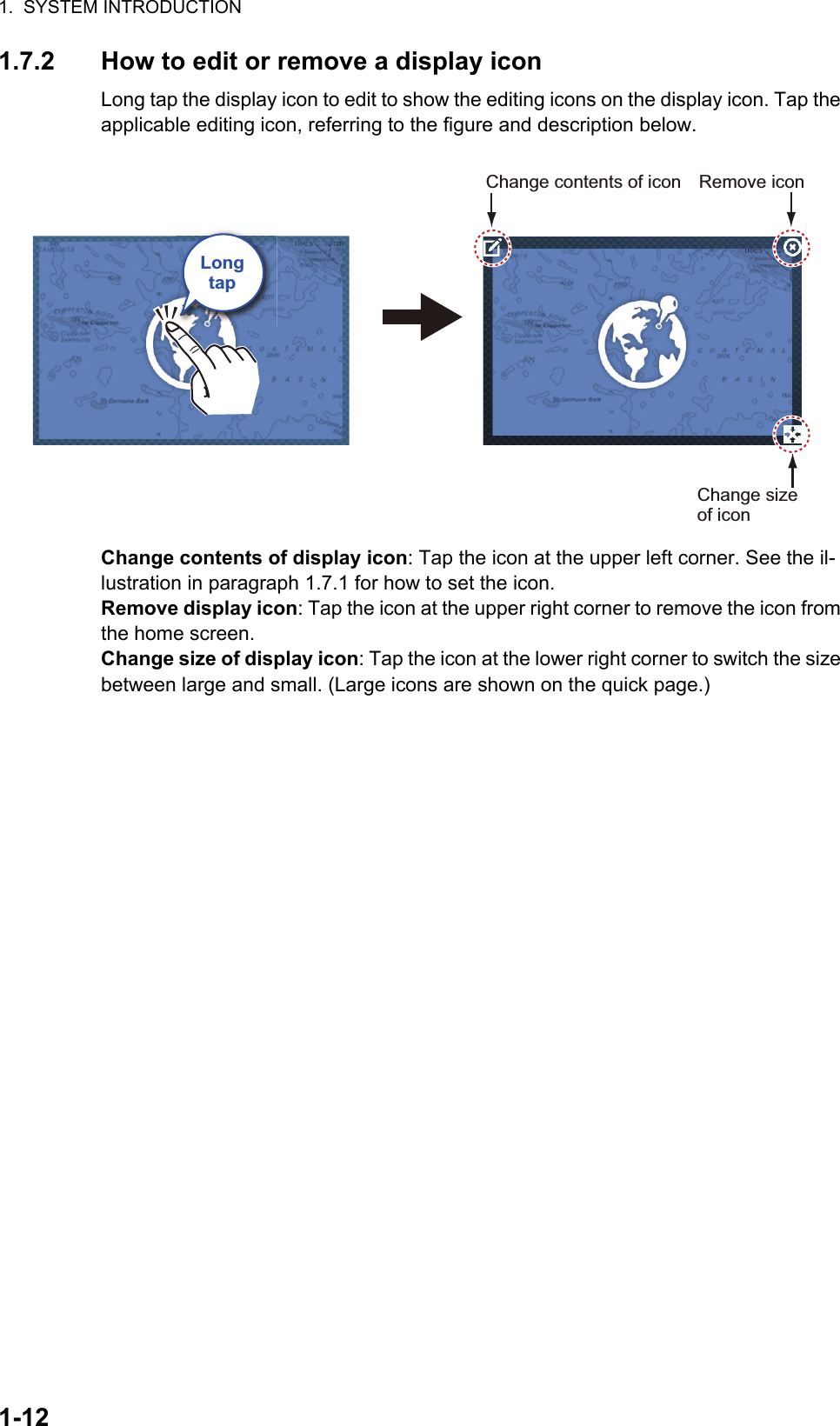
![1. SYSTEM INTRODUCTION1-131.8 Hidden FunctionsThis equipment has five functions that are normally hidden from view: quick page, slide-out menu, pop-up menu, [Layers] menu, and data area (navdata). Swipe or tap the screen at the locations shown below to access the functions. A function window is automatically erased from the screen when it is not operated with the time specified with [User Interface Auto-Hide] in the [General] - [Settings] menu. You can erase the window at any time by tapping the screen.Function descriptionThe quick page selects displays. The display icons set to large size appear on the quick page. (See paragraph 1.6.2.)The slide-out menu provides quick access to often-used functions in the active dis-play. The color of the function name changes according to function status as shown below. Unavailable functions are grayed out.SwipeSwipeSwipeSwipeSwipeSwipeSwipeSwipeSwipeTapSlide-out menuPop-up menuLayers menu*Quick pageData area* Radar sensor connected. [Radar Overlay], [Radar Rings], [Guard Zone 1] and [Guard Zone 2] do not appear with no radar sensor connection.](https://usermanual.wiki/Furuno-USA/9ZWRTR104.User-Manual-II-Part-2/User-Guide-2522486-Page-3.png)
![1. SYSTEM INTRODUCTION1-14The pop-up menu provide a subset of functions that are relevant to the object or lo-cation tapped. Unavailable functions are grayed out.The [Layers] menu mainly controls the items that are displayed on the top layer of the active display. Unavailable functions are grayed out. (This menu can also be accessed from the slide-out menu (where available)). The figure below shows the [Layers] menu for the radar and weather displays.The data area shows navigation data. See the next section for details.Hidden function availability and screen divisionDisplayCamera Instrument Plotter Radar Sounder WeatherLayers No No Yes Yes No YesPop-up Yes Yes Yes Yes Yes YesData area Yes Yes Yes Yes Yes YesQuick page Yes Yes Yes Yes Yes YesSlide-out Yes Yes Yes Yes Yes YesFull screen displays and hidden function availabilityLayers menu for radar displayLayers menu for weather displayABCA: Data area, [Layers] menu, pop-up menu, quick page B: Pop-up menu, quick page, slide-out menuC: [Layers] menu, pop-up menu, slide-out menu Three-way split screen hidden function availability](https://usermanual.wiki/Furuno-USA/9ZWRTR104.User-Manual-II-Part-2/User-Guide-2522486-Page-4.png)
![1. SYSTEM INTRODUCTION1-151.9 Data AreaThe data area at the left side of the screen shows various navigation data, in movable and editable data boxes. You can select the data to display, select format (analog or digital) and change the order of the data. Data availability depends on your system configuration.Note: The data display is also available in the two- and three-way split screens, on the left screen.Two types of data sets are available, navigation data and route data. Select the de-sired set with [DATA] or [ROUTE] at the bottom of the data area.1.9.1 How to change the order of the dataDrag and drop the data boxes to change their order.DataareaDataareaDATA ROUTE RADAR](https://usermanual.wiki/Furuno-USA/9ZWRTR104.User-Manual-II-Part-2/User-Guide-2522486-Page-5.png)
![1. SYSTEM INTRODUCTION1-161.9.2 How to change the contents of a data boxTap the data box to change, and the [MODIFY NAVDATA] pop-up menu appears. Tap the data to use on the pop-up menu.1.9.3 How to add data to a data area1. Tap any unoccupied area in the data area to display the [ADD NAVDATA] pop-up menu.Tap itemto changeTap an itemDATA ROUTE RADARCursororDATA ROUTE RADAR](https://usermanual.wiki/Furuno-USA/9ZWRTR104.User-Manual-II-Part-2/User-Guide-2522486-Page-6.png)
![1. SYSTEM INTRODUCTION1-172. Tap the data to add on the pop-up menu The added data appears at the bottom of the data display. [Cursor information] is added in the example shown below.1.9.4 How to delete a data boxTap the data box to delete, then tap [Remove] on the pop-up menu.DATA ROUTE RADAR](https://usermanual.wiki/Furuno-USA/9ZWRTR104.User-Manual-II-Part-2/User-Guide-2522486-Page-7.png)
![1. SYSTEM INTRODUCTION1-181.9.5 How to switch an indication between analog (graphic) and dig-italTap the data box for which to switch the indication, and the [MODIFY NAVDATA] pop-up menu appears. Use the [Graphic] flipswitch to switch between analog and digital. [ON] for analog, or [OFF] for digital.1.9.6 How to adjust the transparency of the data areaYou can adjust the degree of transparency for the data box with the [NavData Trans-parency] slider (or software keyboard) in the [Settings] - [Plotter] menu. The available degree of transparency is 0 - 80(%). (Alpha blending technology is used for transpar-ency effects.)Analog ([Graphic]: ON)ONDigital ([Graphic]: OFF)NON OFFDATA ROUTE RADAR DATA ROUTE RADAR](https://usermanual.wiki/Furuno-USA/9ZWRTR104.User-Manual-II-Part-2/User-Guide-2522486-Page-8.png)
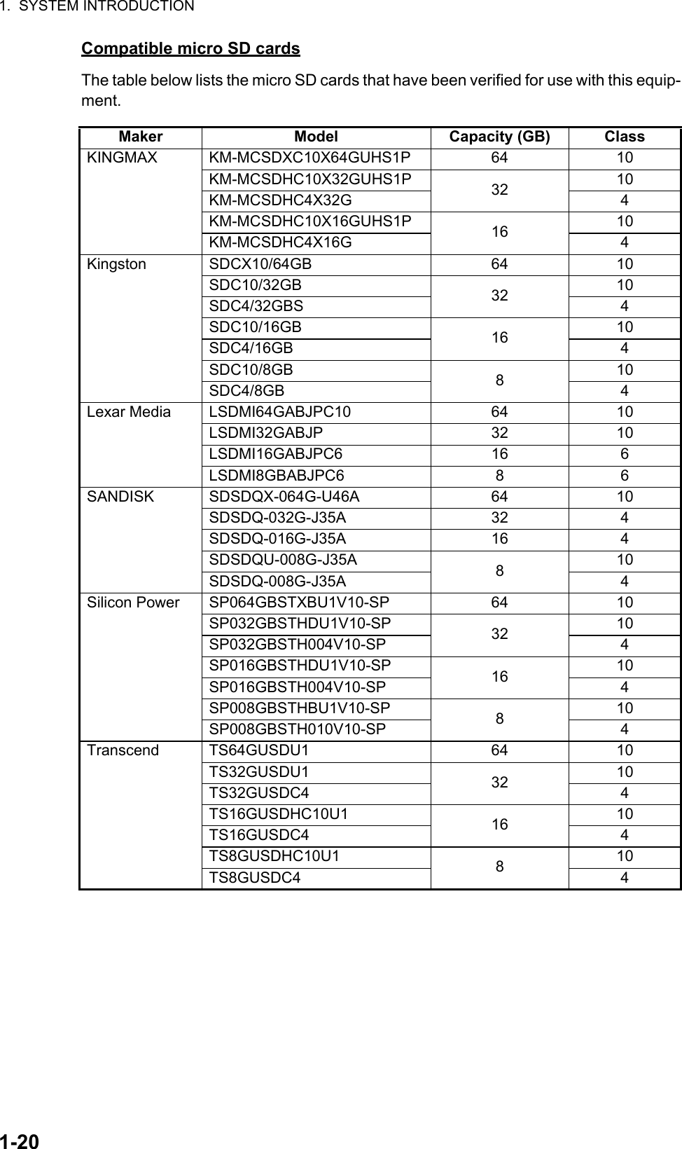
![1. SYSTEM INTRODUCTION1-211.11 Plotter IntroductionThe plotter provides a small world map in raster format. A vector chart for the US coastline (with Alaska and Hawaii) is provided also. The plotter section has functions to enter points, and create and plan routes.The plotter receives position information supplied from the built in GPS receiver. Your position is marked on the screen with the boat icon.The points and routes you have entered are shown on the screen. You can move, de-lete and edit the points and routes from a pop-up menu.The plotter alsoThe status bar, common to all modes, alerts you to equipment status. The color of both the bar and the status message change according to message category.- Red bar, yellow characters: warning (alarm violation, equipment error, etc.)- Yellow bar, black characters: caution (system message, etc.)When an alert condition occurs, the equipment beeps (if enabled), the name of the alert appears in the bar, and the bar flashes. You can stop the flashing and silence the beep by tapping the bar.The undo and redo icons are available for point and route operations.Undo: Reverse the last action.Redo: Repeat the last action.• Plots the track of your ship• Measures distances and bearings• Marks man overboard (MOB) position• Controls alarm functions• Follows routesUndo icon Redo iconSlider barOrientation mode switch2D/3D switchChart rangeActive routePointTrackCOGCOGReturn own ship to screen centerBoat iconBoat iconDataareaDataareaHome iconInactive route(Departure orarrival point,selectable on [Layers menu])HeadinglineHeadinglineDepth AlarmStatus barDATA ROUTE RADAR](https://usermanual.wiki/Furuno-USA/9ZWRTR104.User-Manual-II-Part-2/User-Guide-2522486-Page-11.png)