Furuno USA 9ZWRTR104 Transceiver for Radar Sensor DRS4DL User Manual
Furuno USA Inc Transceiver for Radar Sensor DRS4DL
Contents
- 1. User Manual I
- 2. User Manual II Part 1
- 3. User Manual II Part 2
- 4. User Manual II Part 3
- 5. User Manual II Part 4
- 6. User Manual II Part 5
- 7. User Manual II Part 6
- 8. User Manual II Part 7
- 9. User Manual II Part 8
- 10. User Manual II Part 9
- 11. User Manual II Part 10
- 12. User Manual II Part 11
- 13. User Manual II Part 12
User Manual II Part 2
1. SYSTEM INTRODUCTION
1-11
1.7 How to Edit the Display Icons
The default home screen arrangement provides seven displays in configurations ac-
cording to the equipment that you have in your network. If the arrangement does not
meet your requirements, you can change the display icons as required. You can set a
maximum of 10 display icons to show, and split a display screen up to three ways. For
example, you can show the radar and sounder (fish finder) displays in a two-way split
screen.
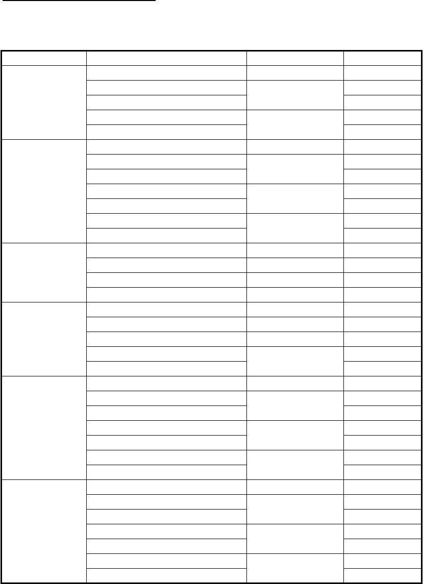
The screen can be a full-screen, two-way split or three-way split. The displays avail-
able depend on the display division selected and your system configuration. The table
below outlines the display divisions and possible displays.
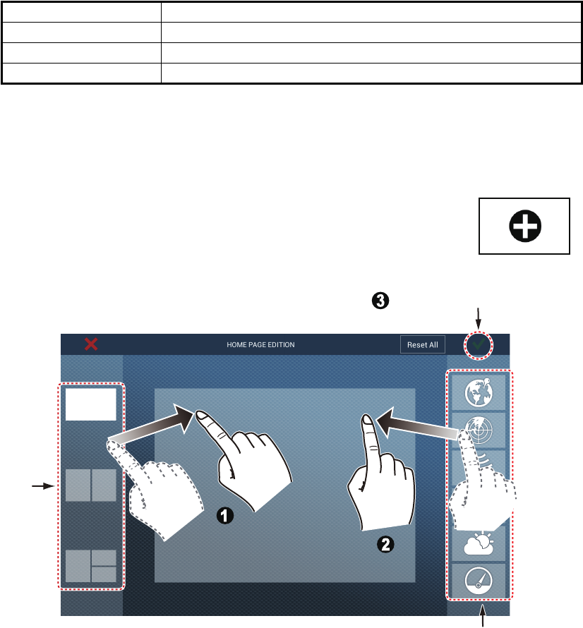
1.7.1 How to add a new display icon
1. Tap the [Home] icon to show the home screen.
2. Tap the + icon. (If the icon is not shown, this means the capacity
for display icons has been reached. Erase an unnecessary icon
to make room. See paragraph 1.7.2.)
3. Follow the instructions below to create a display icon.
Your arrangement is then opened on the screen and the home screen is updated ac-
cording to your arrangement.
Display division Available displays
Full Plotter, weather, radar, sounder, instrument, camera
Two-way split Plotter, radar, sounder
Three-way split Plotter, radar, sounder, instrument, camera
Available displays
Display
division
Custom display area
Custom display area
Drag
display
division
Drag
display
division
Drag
display
type
Drag
display
type
Tap to save icon.

1. SYSTEM INTRODUCTION
1-12
1.7.2 How to edit or remove a display icon
Long tap the display icon to edit to show the editing icons on the display icon. Tap the
applicable editing icon, referring to the figure and description below.
Change contents of display icon: Tap the icon at the upper left corner. See the il-
lustration in paragraph 1.7.1 for how to set the icon.
Remove display icon: Tap the icon at the upper right corner to remove the icon from
the home screen.
Change size of display icon: Tap the icon at the lower right corner to switch the size
between large and small. (Large icons are shown on the quick page.)
Long
tap
Remove icon
Change size
of icon
Change contents of icon
1. SYSTEM INTRODUCTION
1-13
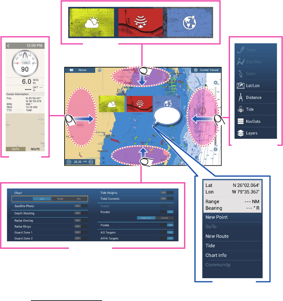
1.8 Hidden Functions
This equipment has five functions that are normally hidden from view: quick page,
slide-out menu, pop-up menu, [Layers] menu, and data area (navdata). Swipe or tap
the screen at the locations shown below to access the functions.
A function window is automatically erased from the screen when it is not operated with
the time specified with [User Interface Auto-Hide] in the [General] - [Settings] menu.
You can erase the window at any time by tapping the screen.
Function description
The quick page selects displays. The display icons set to large size appear on the
quick page. (See paragraph 1.6.2.)
The slide-out menu provides quick access to often-used functions in the active dis-
play. The color of the function name changes according to function status as shown
below. Unavailable functions are grayed out.
Swipe
Swipe
Swipe
Swipe
Swipe
Swipe
Swipe
Swipe
Swipe
Tap
Slide-out menu
Pop-up menu
Layers menu*
Quick page
Data area
* Radar sensor connected. [Radar Overlay], [Radar Rings],
[Guard Zone 1] and [Guard Zone 2] do not appear with no
radar sensor connection.
1. SYSTEM INTRODUCTION
1-14
The pop-up menu provide a subset of functions that are relevant to the object or lo-
cation tapped. Unavailable functions are grayed out.
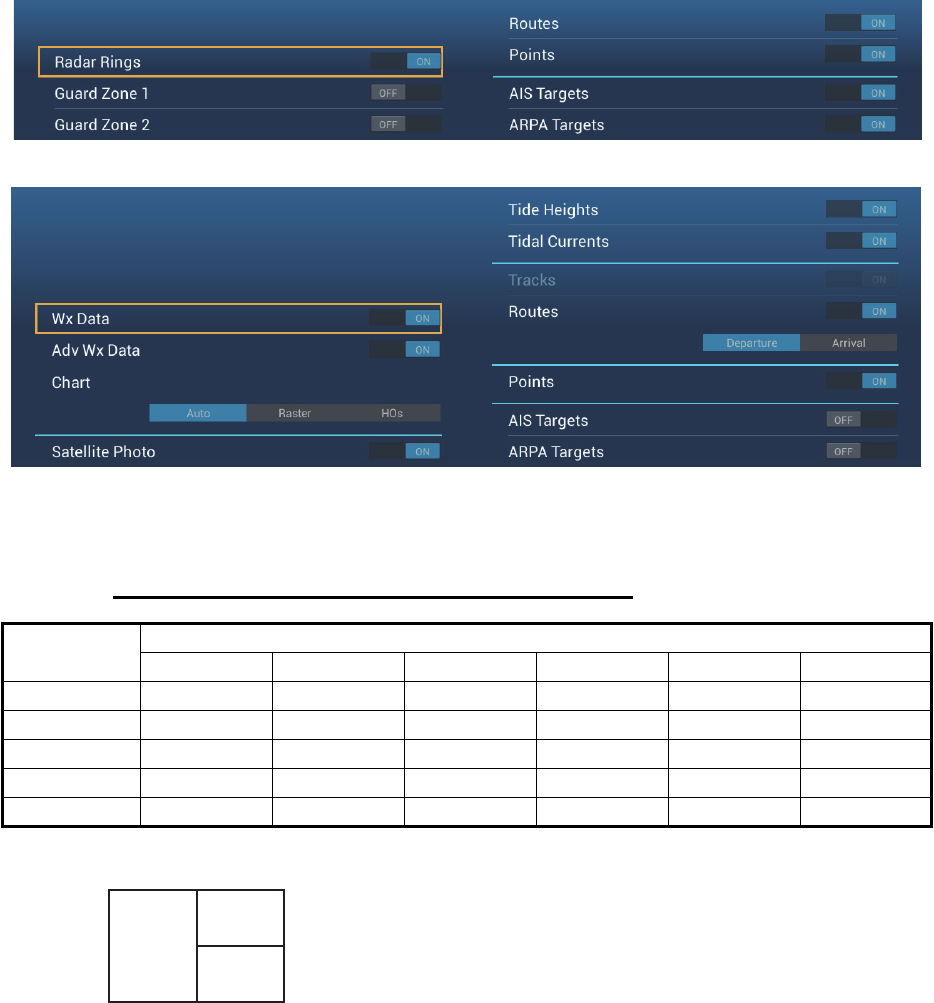
The [Layers] menu mainly controls the items that are displayed on the top layer of the
active display. Unavailable functions are grayed out. (This menu can also be accessed
from the slide-out menu (where available)). The figure below shows the [Layers] menu
for the radar and weather displays.
The data area shows navigation data. See the next section for details.
Hidden function availability and screen division
Display
Camera Instrument Plotter Radar Sounder Weather
Layers No No Yes Yes No Yes
Pop-up Yes Yes Yes Yes Yes Yes
Data area Yes Yes Yes Yes Yes Yes
Quick page Yes Yes Yes Yes Yes Yes
Slide-out Yes Yes Yes Yes Yes Yes
Full screen displays and hidden function availability
Layers menu for radar display
Layers menu for weather display
A
B
C
A: Data area, [Layers] menu, pop-up menu, quick page
B: Pop-up menu, quick page, slide-out menu
C: [Layers] menu, pop-up menu, slide-out menu
Three-way split screen hidden function availability
1. SYSTEM INTRODUCTION
1-15
1.9 Data Area
The data area at the left side of the screen shows various navigation data, in movable
and editable data boxes. You can select the data to display, select format (analog or
digital) and change the order of the data. Data availability depends on your system
configuration.
Note: The data display is also available in the two- and three-way split screens, on the
left screen.
Two types of data sets are available, navigation data and route data. Select the de-
sired set with [DATA] or [ROUTE] at the bottom of the data area.
1.9.1 How to change the order of the data
Drag and drop the data boxes to change their order.
Data
area
Data
area
DATA ROUTE RADAR
1. SYSTEM INTRODUCTION
1-16
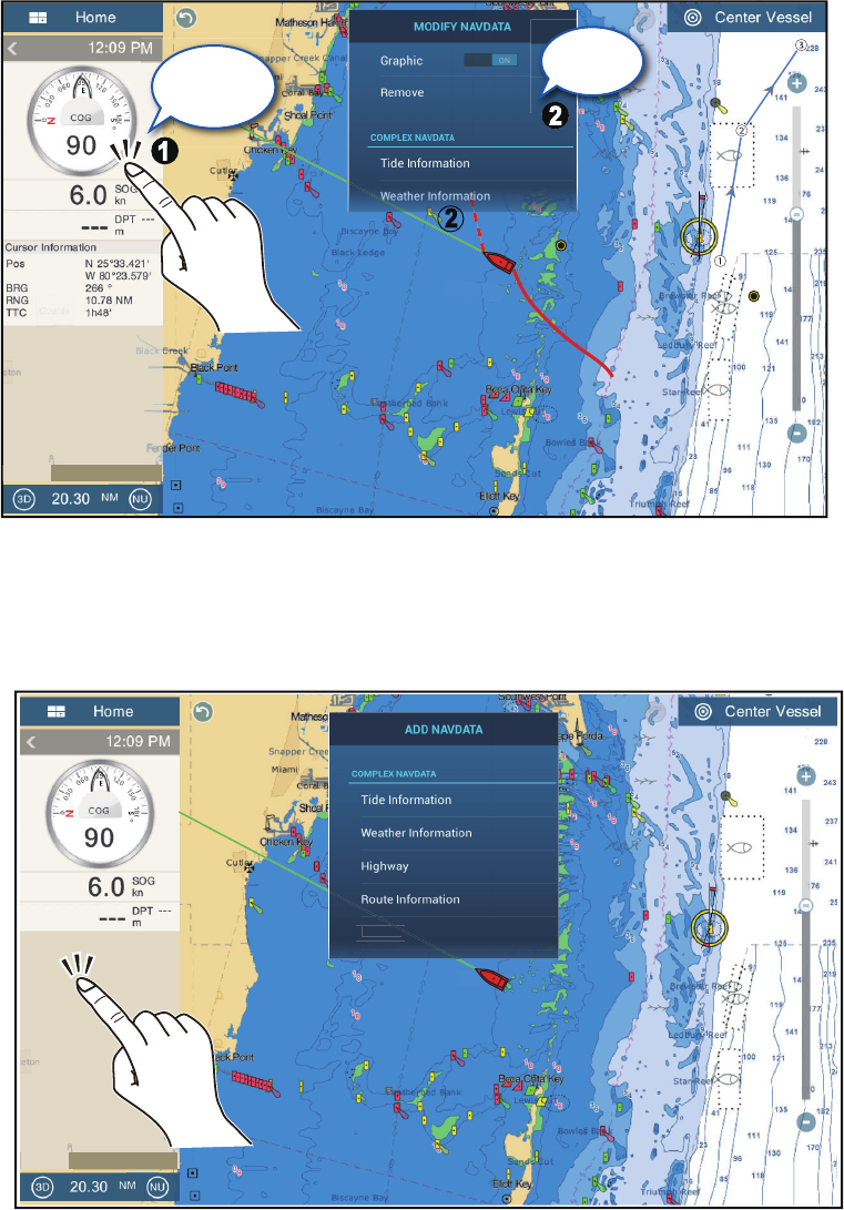
1.9.2 How to change the contents of a data box
Tap the data box to change, and the [MODIFY NAVDATA] pop-up menu appears. Tap
the data to use on the pop-up menu.
1.9.3 How to add data to a data area
1. Tap any unoccupied area in the data area to display the [ADD NAVDATA] pop-up
menu.
Tap item
to change
Tap an
item
DATA ROUTE RADAR
Cursor
or
DATA ROUTE RADAR
1. SYSTEM INTRODUCTION
1-17
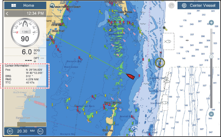
2. Tap the data to add on the pop-up menu The added data appears at the bottom
of the data display. [Cursor information] is added in the example shown below.
1.9.4 How to delete a data box
Tap the data box to delete, then tap [Remove] on the pop-up menu.
DATA ROUTE RADAR
1. SYSTEM INTRODUCTION
1-18
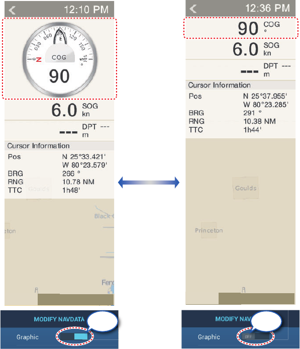
1.9.5 How to switch an indication between analog (graphic) and dig-
ital
Tap the data box for which to switch the indication, and the [MODIFY NAVDATA] pop-
up menu appears. Use the [Graphic] flipswitch to switch between analog and digital.
[ON] for analog, or [OFF] for digital.
1.9.6 How to adjust the transparency of the data area
You can adjust the degree of transparency for the data box with the [NavData Trans-
parency] slider (or software keyboard) in the [Settings] - [Plotter] menu. The available
degree of transparency is 0 - 80(%). (Alpha blending technology is used for transpar-
ency effects.)
Analog ([Graphic]: ON)
ON
Digital ([Graphic]: OFF)
N
ON OFF
DATA ROUTE RADAR DATA ROUTE RADAR
1. SYSTEM INTRODUCTION
1-19
1.10 Micro SD Cards
This equipment uses two types of micro SD cards, chart and data. The chart cards
contain charts and the data micro SD card stores plotter-related data such as tracks,
routes, points and generic data such as menu settings. Set and remove the card as
shown below. The Secure Digital Extended Capacity (SDXC) cards can also be used.
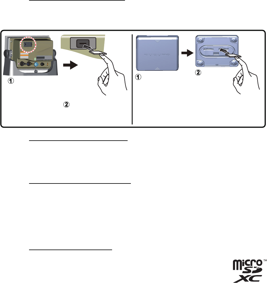
How to insert a micro SD card
Before inserting a chart card in the multi function display, turn off the power.
How to format a micro SD card
You do not normally need to format a data micro SD card. If the card becomes unread-
able, format the card with a formatting program that is compatible with the specifica-
tions of the micro SD card.
How to remove a micro SD card
1) Open the card slot cover at the rear of the display unit. (Remove the cover in case
of the SD card unit.)
2) Push the card to release the card from the card drive.
3) Remove the card with your fingers then close the lid (cover).
4) Close the card slot lid.
About the micro SD cards
• Handle the cards carefully. Improper use can damage the card and
destroy its contents.
• Make sure the slot lid (cover) is closed at all times.
• Remove a card with only your fingers. Do not use metal instruments
(like tweezers) to remove the card.
• Do not remove a card during the reading of or writing to the card.
Note: Use a micro SD card class 6 or higher for storing chart data.
Unfasten two
screws.
Push card into slot.
SD card unit (SDU-001)Chart card drive (multi function display)
Remove
cover.
Push card
into slot*.
* Right slot is for data card; left slot is for chart
card.
1. SYSTEM INTRODUCTION
1-20
Compatible micro SD cards
The table below lists the micro SD cards that have been verified for use with this equip-
ment.
Maker Model Capacity (GB) Class
KINGMAX KM-MCSDXC10X64GUHS1P 64 10
KM-MCSDHC10X32GUHS1P 32 10
KM-MCSDHC4X32G 4
KM-MCSDHC10X16GUHS1P 16 10
KM-MCSDHC4X16G 4
Kingston SDCX10/64GB 64 10
SDC10/32GB 32 10
SDC4/32GBS 4
SDC10/16GB 16 10
SDC4/16GB 4
SDC10/8GB 810
SDC4/8GB 4
Lexar Media LSDMI64GABJPC10 64 10
LSDMI32GABJP 32 10
LSDMI16GABJPC6 16 6
LSDMI8GBABJPC6 8 6
SANDISK SDSDQX-064G-U46A 64 10
SDSDQ-032G-J35A 32 4
SDSDQ-016G-J35A 16 4
SDSDQU-008G-J35A 810
SDSDQ-008G-J35A 4
Silicon Power SP064GBSTXBU1V10-SP 64 10
SP032GBSTHDU1V10-SP 32 10
SP032GBSTH004V10-SP 4
SP016GBSTHDU1V10-SP 16 10
SP016GBSTH004V10-SP 4
SP008GBSTHBU1V10-SP 810
SP008GBSTH010V10-SP 4
Transcend TS64GUSDU1 64 10
TS32GUSDU1 32 10
TS32GUSDC4 4
TS16GUSDHC10U1 16 10
TS16GUSDC4 4
TS8GUSDHC10U1 810
TS8GUSDC4 4
1. SYSTEM INTRODUCTION
1-21
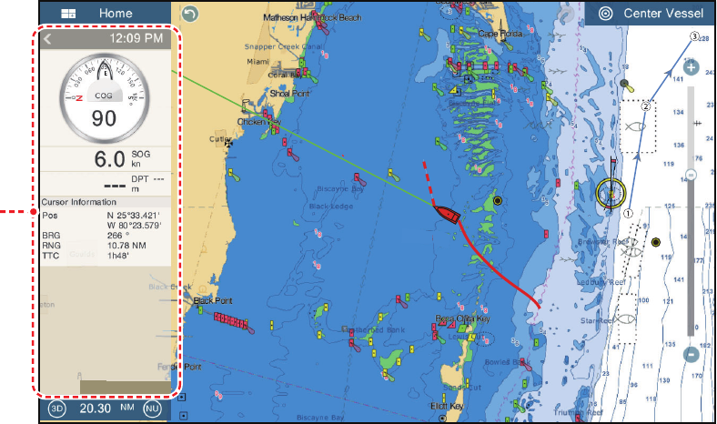
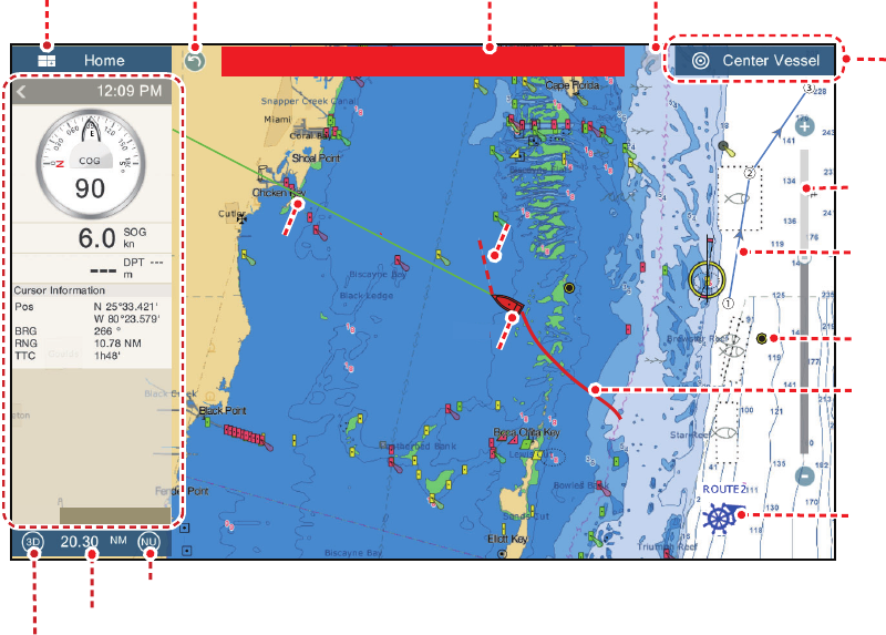
1.11 Plotter Introduction
The plotter provides a small world map in raster format. A vector chart for the US
coastline (with Alaska and Hawaii) is provided also. The plotter section has functions
to enter points, and create and plan routes.
The plotter receives position information supplied from the built in GPS receiver. Your
position is marked on the screen with the boat icon.
The points and routes you have entered are shown on the screen. You can move, de-
lete and edit the points and routes from a pop-up menu.
The plotter also
The status bar, common to all modes, alerts you to equipment status. The color of
both the bar and the status message change according to message category.
- Red bar, yellow characters: warning (alarm violation, equipment error, etc.)
- Yellow bar, black characters: caution (system message, etc.)
When an alert condition occurs, the equipment beeps (if enabled), the name of the
alert appears in the bar, and the bar flashes. You can stop the flashing and silence the
beep by tapping the bar.
The undo and redo icons are available for point and route operations.
Undo: Reverse the last action.
Redo: Repeat the last action.
• Plots the track of your ship
• Measures distances and bearings
• Marks man overboard (MOB) position
• Controls alarm functions
• Follows routes
Undo icon Redo icon
Slider bar
Orientation mode switch
2D/3D switch
Chart range
Active route
Point
Track
COG
COG
Return own
ship to
screen
center
Boat icon
Boat icon
Data
area
Data
area
Home icon
Inactive route
(Departure or
arrival point,
selectable on
[Layers menu])
Heading
line
Heading
line
Depth Alarm
Status bar
DATA ROUTE RADAR
1. SYSTEM INTRODUCTION
1-22
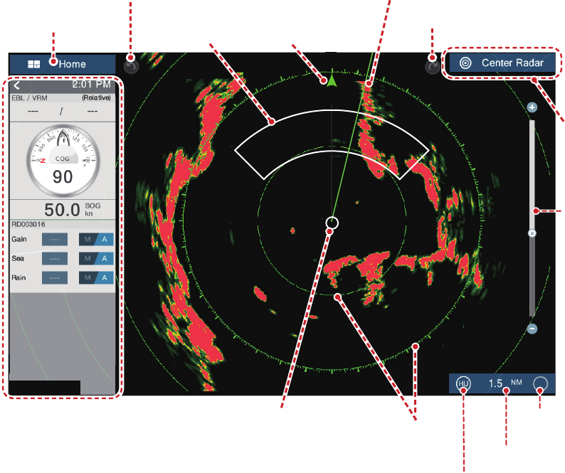
1.12 Radar Introduction
A radar system operates in the microwave part of the radio frequency (RF) range. The
radar detects the position and movement of objects. Objects are shown on the radar
display at their measured distances and bearings in intensities according to echo
strength.
The radar display is available in head-up and north-up modes and orientation in true
and relative motion. The relative motion display shows other ships movement relative
to your ship. The true motion display shows your ship and other objects in motion ac-
cording to their true courses and speeds.
A guard zone tells you when the radar targets are in the area you indicate. The trail of
targets can be shown in afterglow to monitor their movements.
Own ship position
Own ship position
Home icon
Undo icon
Guard zone
Guard zone
North mark
North mark
Slider
bar
Return own
ship icon to
screen
center.
Data
area
Data
area
Heading line
Heading line
Redo icon
㔎㔐
0
10
20
30
40
50
60
70
80
90
100
110
120
200
230
240
250 260 270
280
290
300
310
320
330
340
350
210
180
170
160
140
220
190
150
130
340
Range
TX/Standby
switch
Orientation mode switch
Fixed range
rings
Data
area
Data
area
TX
RADAR
DATA ROUTE