Furuno USA 9ZWRTR104 Transceiver for Radar Sensor DRS4DL User Manual
Furuno USA Inc Transceiver for Radar Sensor DRS4DL
Contents
- 1. User Manual I
- 2. User Manual II Part 1
- 3. User Manual II Part 2
- 4. User Manual II Part 3
- 5. User Manual II Part 4
- 6. User Manual II Part 5
- 7. User Manual II Part 6
- 8. User Manual II Part 7
- 9. User Manual II Part 8
- 10. User Manual II Part 9
- 11. User Manual II Part 10
- 12. User Manual II Part 11
- 13. User Manual II Part 12
User Manual II Part 7
6. RADAR
6-4
6.5 How to Reduce the Rain Clutter
When your ship is in or near rain or snow, the reflections from rain or snow appear on
the screen. These reflections have the name “rain clutter”. When the rain clutter is
strong, targets in or near the rain clutter are hidden in the clutter. Reflections from the
rain clutter are easily identified from true targets by their wool-like appearance.
The rain control breaks the continuous display of rain or snow reflections into a ran-
dom pattern. The rain control also helps to reduce the target clutter in good weather
in busy harbors. When the rain clutter hides targets, adjust the rain control (automatic
or manual) to reduce the clutter. After the rain clutter is gone, turn off the rain control
to prevent the loss of targets.
Like with gain, rain clutter can be adjusted from the pop-up menu or data area. See
the procedures in section 6.3.
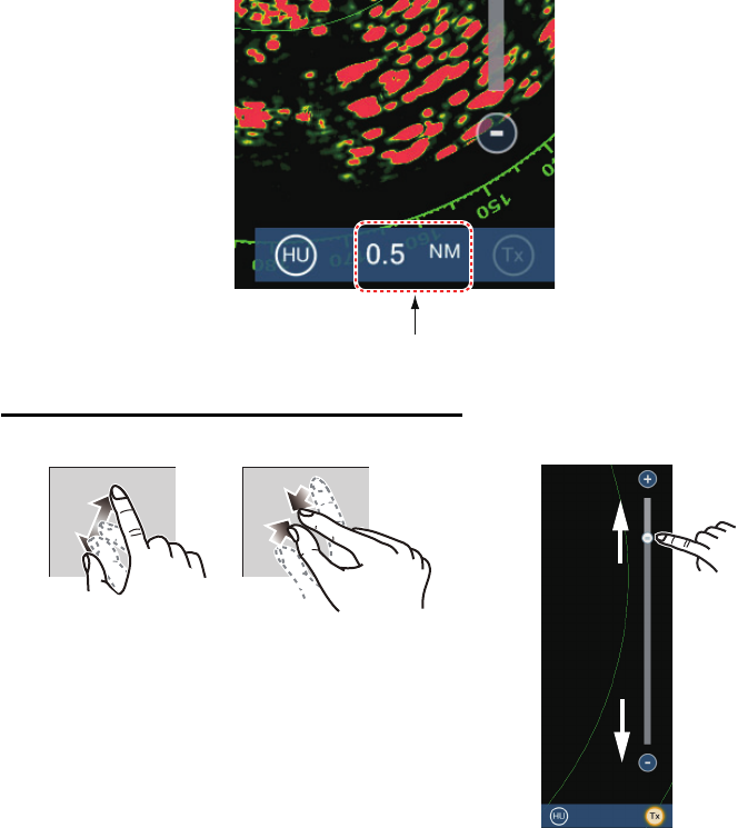
6.6 Range Scale
The range setting controls the size of the area (in nautical miles, kilometers or statute
miles) that appears on your screen. The range appears at the bottom right-hand cor-
ner of the screen.
How to zoom in or out the range scale
Range
Zoom in Zoom out
Method 1: Pinch screen
Method 2: Drag slider
3 NM
Zoom in
Zoom in
Zoom out
Zoom out
6. RADAR
6-5
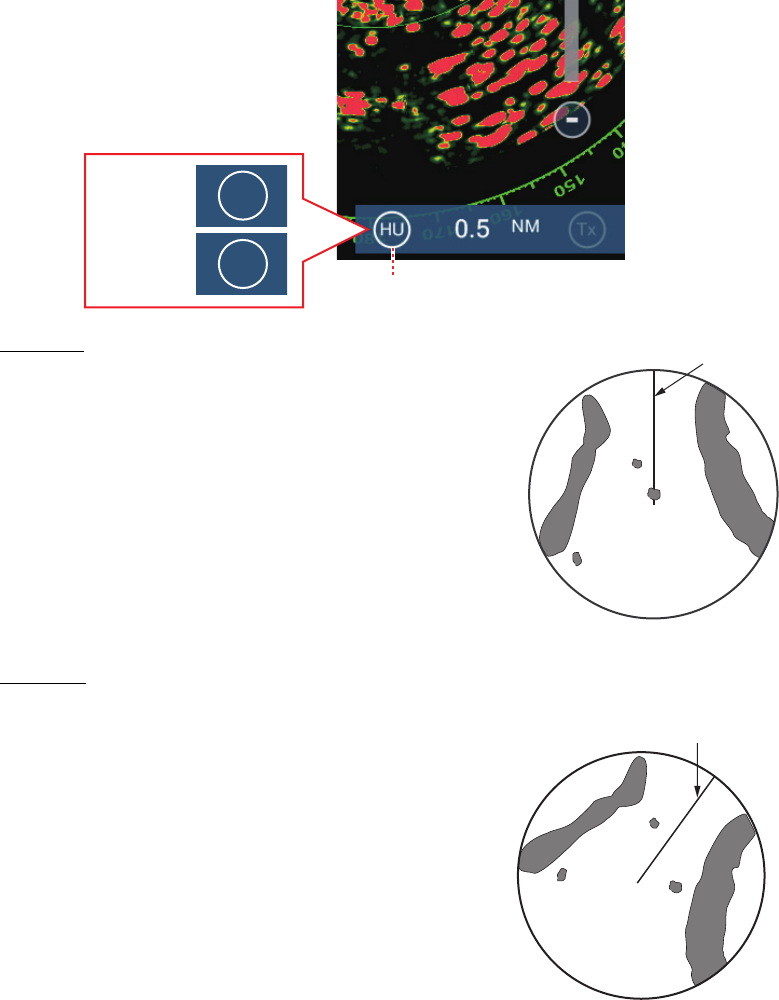
6.7 Orientation Mode
The orientation mode controls the relationship between your ship and all the other tar-
gets.
The heading data is required in the north-up mode. When the heading data is lost, the
orientation mode automatically goes to head-up. Restore the compass signal to show
the heading indication. Select the orientation mode again if necessary.
To select an orientation mode, tap the orientation mode icon [HU] (or [NU], whichever
is shown) icon at the bottom right corner of the screen to show [HU] (Head-up) or [NU]
(North-up) as required.
Head-up
A display without azimuth stabilization in which the
line that connects the center with the top of the
screen indicates your heading. Targets are shown at
their measured distances and in their directions rela-
tive to your heading.
North-up
Targets are shown at their measured distances and
their true (compass) directions from your ship. North
is at the top of the screen. The heading line changes
its direction according to your heading.
Orienatation mode switch
HU
NU
Head-up:
North-up:
Heading line
Heading line
6. RADAR
6-6
6.8 How to Measure the Range and Bearing from
Your Ship to a Target
You can measure the range or bearing to a target by the following four methods.
6.8.1 How to display the range rings
The range rings are the concentric solid circles about your ship. Use the fixed range
rings to get a rough estimate of the range to a target.
To show or hide the range rings, open the [Layers] menu then turn [Radar Rings] on
or off as required.
To measure the range with the range rings, count the number of rings between the
center of the screen and the target. Check the range ring interval and estimate the dis-
tance of the echo from the inner edge of the nearest ring.
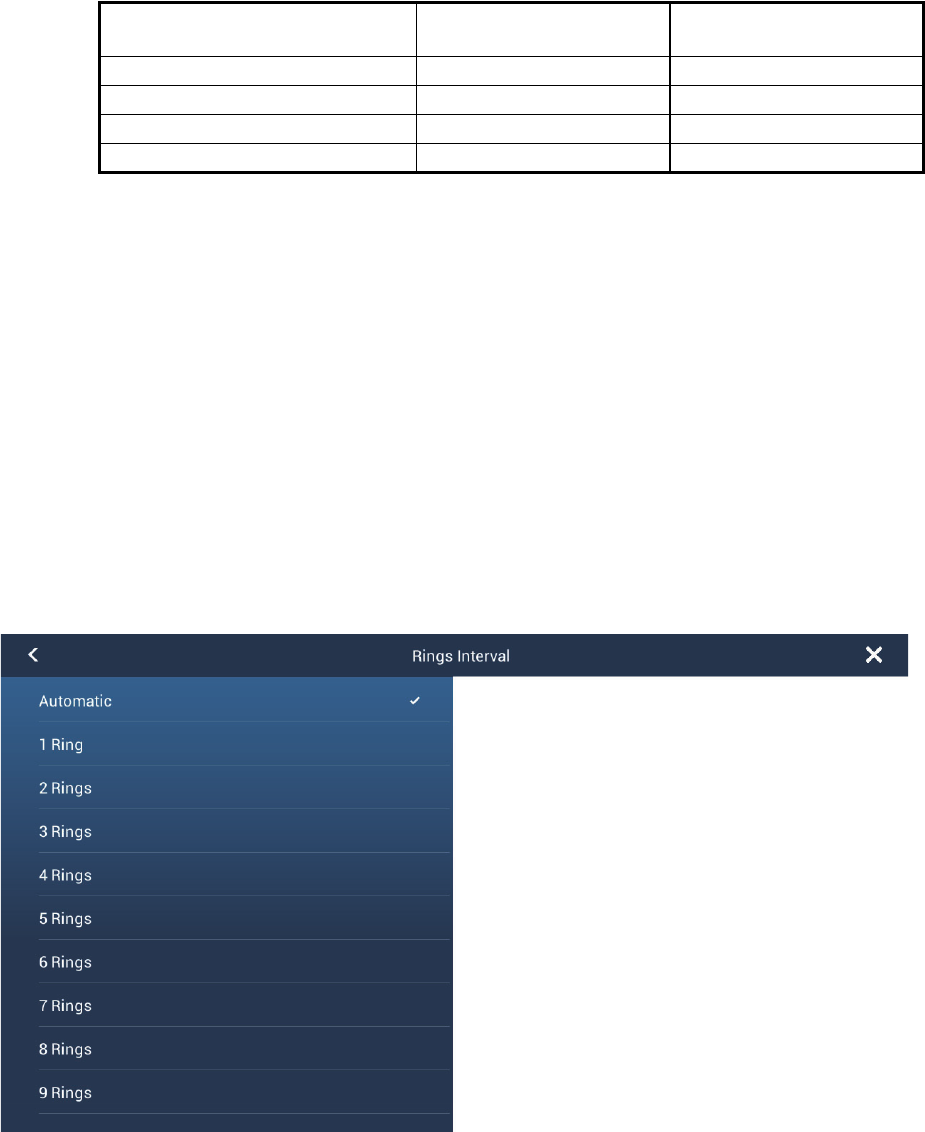
6.8.2 How to set the number of the range rings to show
1. Open the home screen, then tap [Settings] - [Radar].
2. Tap [Rings Interval].
3. Tap a number. [Automatic] automatically selects the number of rings according to
the range scale.
4. Tap the close button to finish.
Range
measurement
Bearing
measurement
Fixed range rings Yes No
Ruler Yes Yes
VRM (Variable Range Marker) Yes No
EBL (Electronic Bearing Line) No Yes
6. RADAR
6-7
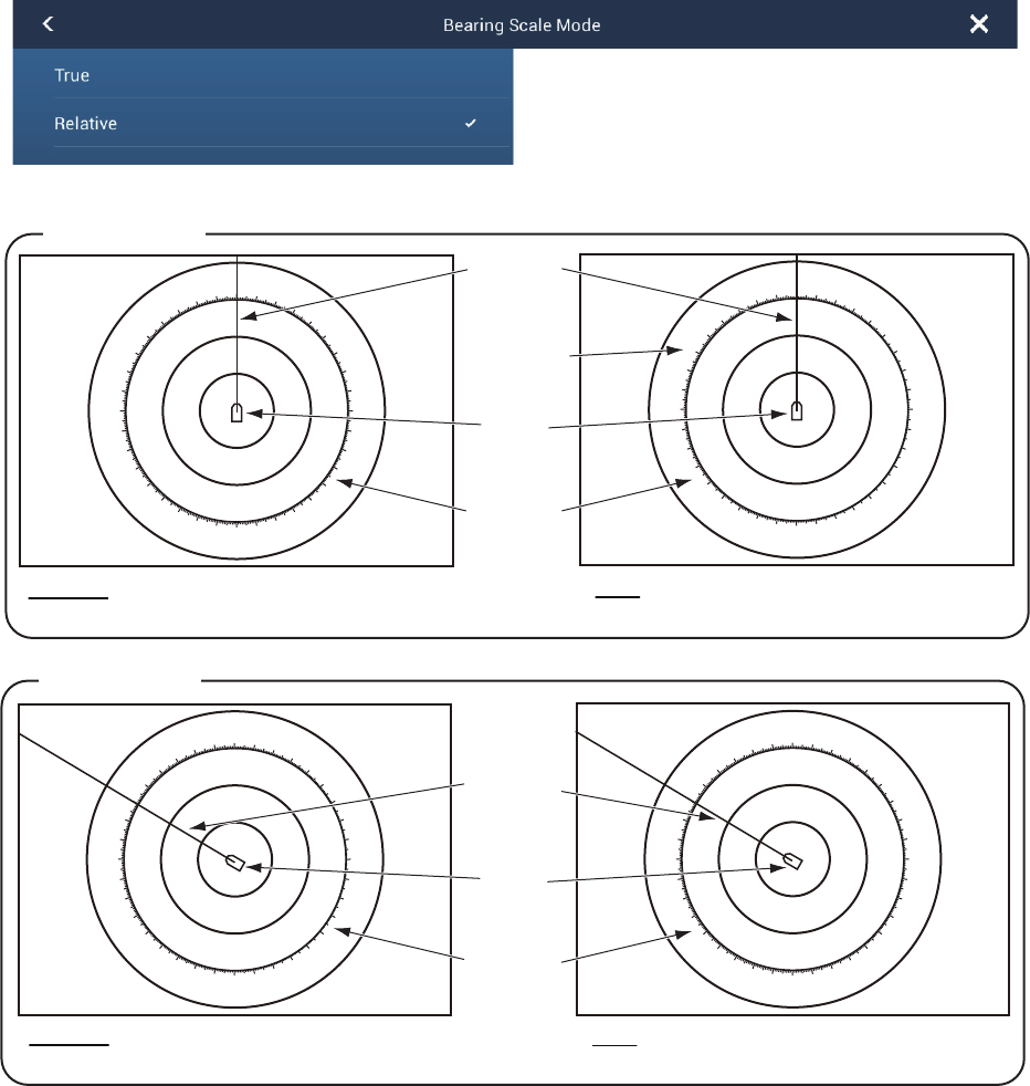
6.8.3 How to select the range rings mode
To select the range rings mode, open the home screen, then tap [Settings] - [Radar].
Set [Bearing Scale Mode] and [Relative] or [True].
Relative: Bearing scale is fixed and “0” is
at the top of the screen.
Boat
icon
010 20
30
40
50
60
70
80
90
100
110
120
130
140
150
160
170
180
190
200
210
220
230
240
250
260
270
280
290
300
310
320
330
340 350
0
10
20
30
40 50 60 70 80
90
100
110
120
130
140
150
160
170
180
190
200
210
220
230
240
250
260
270
280
290
300
310
320
330
340
350
010 20
30
40
50
60
70
80
90
100
110
120
130
140
150
160
170
180
190
200
210
220
230
240
250
260
270
280
290
300
310
320
330
340 350
0
10
20
30
40 50 60 70 80
90
100
110
120
130
140
150
160
170
180
190
200
210
220
230
240
250
260
270
280
290
300
310
320
330
340
350
North (“0”)
Heading
line
Bearing
scale
True: Bearing scale rotates according to
the movement of your ship.
Head-up mode
North-up mode
Relative: Bearing scale rotates according
to the movement of your ship.
True: Bearing scale is fixed and “0” is at
the top of the screen.
Boat
icon
Bearing
scale
Heading
line
6. RADAR
6-8
6.8.4 How to measure the range and bearing
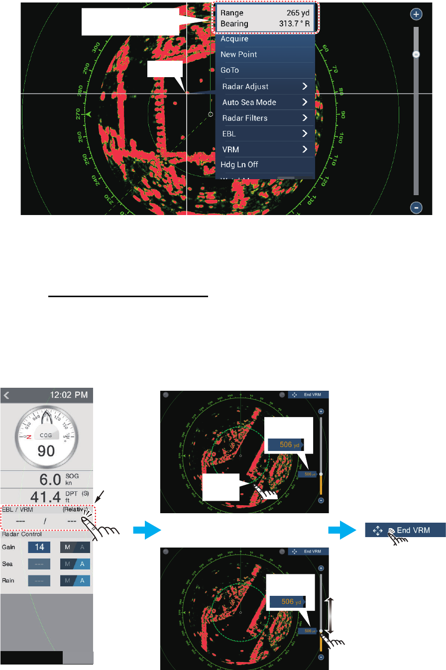
Tap an object to get the range and bearing. Read the range and bearing in the box.
6.8.5 How to measure the range with the VRM
The VRM is a dashed ring so that you can identify the ring from the fixed range rings.
Method 1: From the data area
Open the data area. Tap the VRM indication in the [EBL/VRM] data box. Drag the
VRM or slider to set the VRM. Tap [End VRM] to anchor the VRM and finish. The
range to the VRM appears to the left of the slider bar and in the [EBL/VRM] data box.
To clear the VRM, open the pop-up menu, the tap [EBL] and [Clear].
Object
Range and bearing
to object
Tap
here.
OR
Drag
slider
Drag
slider
Tap [End VRM]
to anchor VRM
and exit.
Drag
VRM
EBL/VRM
data box
Drag
VRM
Drag
VRM
Range to
object
Range to
object
RADAR
DATA ROUTE
6. RADAR
6-9
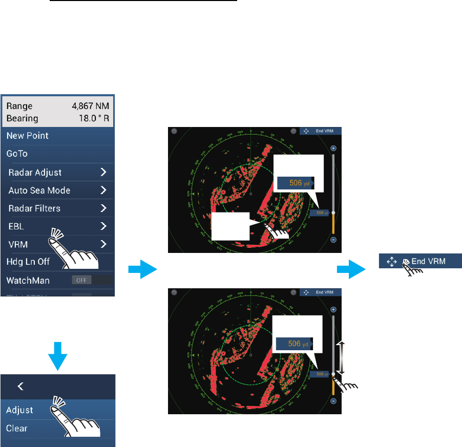
Method 2: From the pop-up menu
Tap the screen to show the pop-up menu, then tap [VRM]. Drag the VRM or slider to
set the VRM. Tap [End VRM] to anchor the VRM and finish. The range to the VRM
appears to the left of the slider bar.
To clear the VRM, open the pop-up menu, the tap [VRM] and [Clear].
Drag
slider
Drag
slider
OR
Drag
VRM
Drag
VRM
Drag
VRM
Tap screen to show
pop-up menu.
Tap [VRM].
Tap [Adjust].
Tap [End VRM]
to anchor VRM
and exit.
Range to
object
Range to
object
6. RADAR
6-10
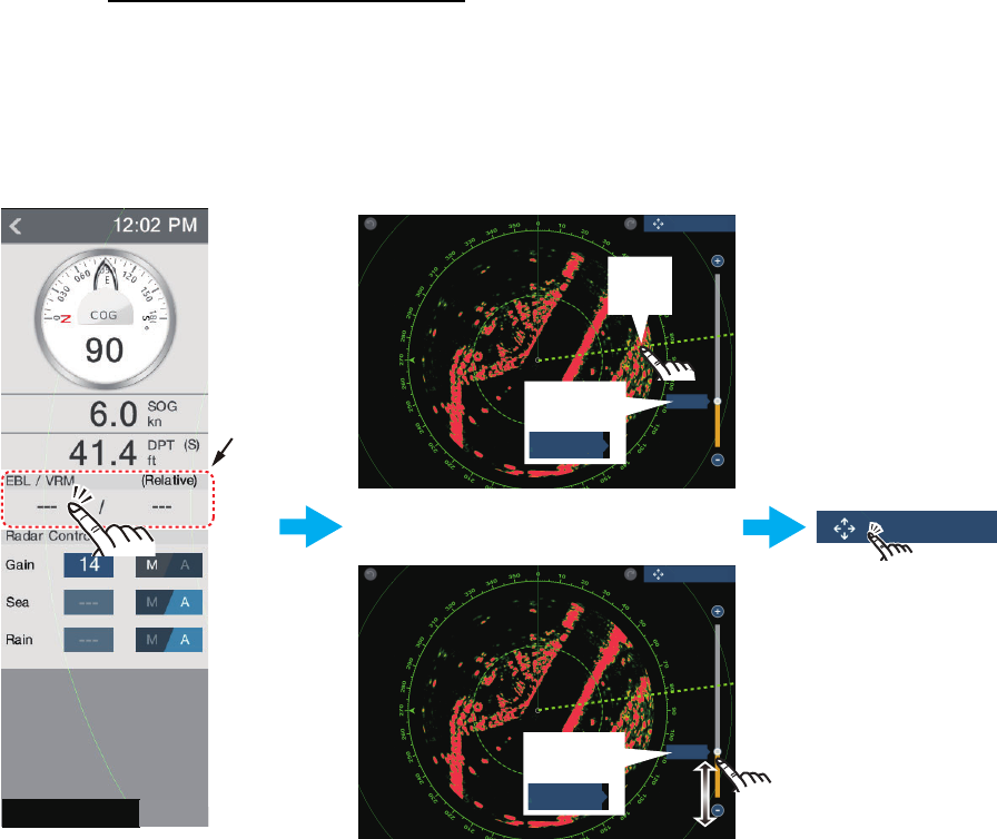
6.8.6 How to measure the bearing with the EBL
Method 1: From the data area
Open the data area. Tap the EBL indication in the [EBL/VRM] data box. Drag the EBL
or slider to set the EBL. Tap [End EBL] to anchor the EBL and finish. The range to the
VRM appears to the left of the slider bar and in the [EBL/VRM] data box.
To clear the EBL, open the pop-up menu, then tap [EBL] and [Clear].
OR
Drag
slider
Drag
slider
Tap [End EBL]
to anchor EBL
and exit.
Drag
VRM
EBL/VRM
data box
84.7°
84.7°
Bearing
to object
84.7°
Drag
EBL
Bearing
to object
84.7°
End EBL
End EBL
End EBL
RADAR
DATA ROUTE
6. RADAR
6-11
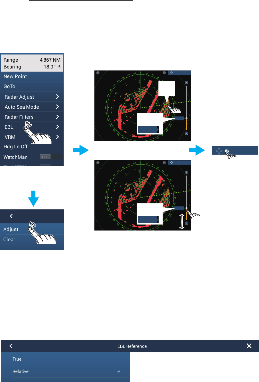
Method 2: From the pop-up menu
Tap the screen to show the pop-up menu, then tap [EBL]. Drag the EBL or slider to
set the EBL. Tap [End EBL] to anchor the EBL and finish. The range to the EBL ap-
pears to the left of the slider bar.
To clear the EBL, open the pop-up menu, then tap [EBL] and [Clear].
6.8.7 How to select the EBL reference
You can select the EBL reference from [True] or [Relative]. [True] means the bearing
is in reference to the north. [Relative] means the bearing is relative to the heading of
your ship. True bearing requires a heading sensor.
1. Open the home screen, then tap [Settings] - [Radar].
2. Tap [EBL Reference].
3. Tap [True] or [Relative].
4. Tap the close button to finish.
Tap screen to show
pop-up menu.
Tap [EBL].
Tap [Adjust].
OR
Drag
slider
Drag
slider
Tap [End EBL]
to anchor EBL
and exit.
Drag
VRM
84.7°
84.7°
Bearing
to object
84.7°
Drag
EBL
Bearing
to object
84.7°
End EBL
End EBL
End EBL
6. RADAR
6-12
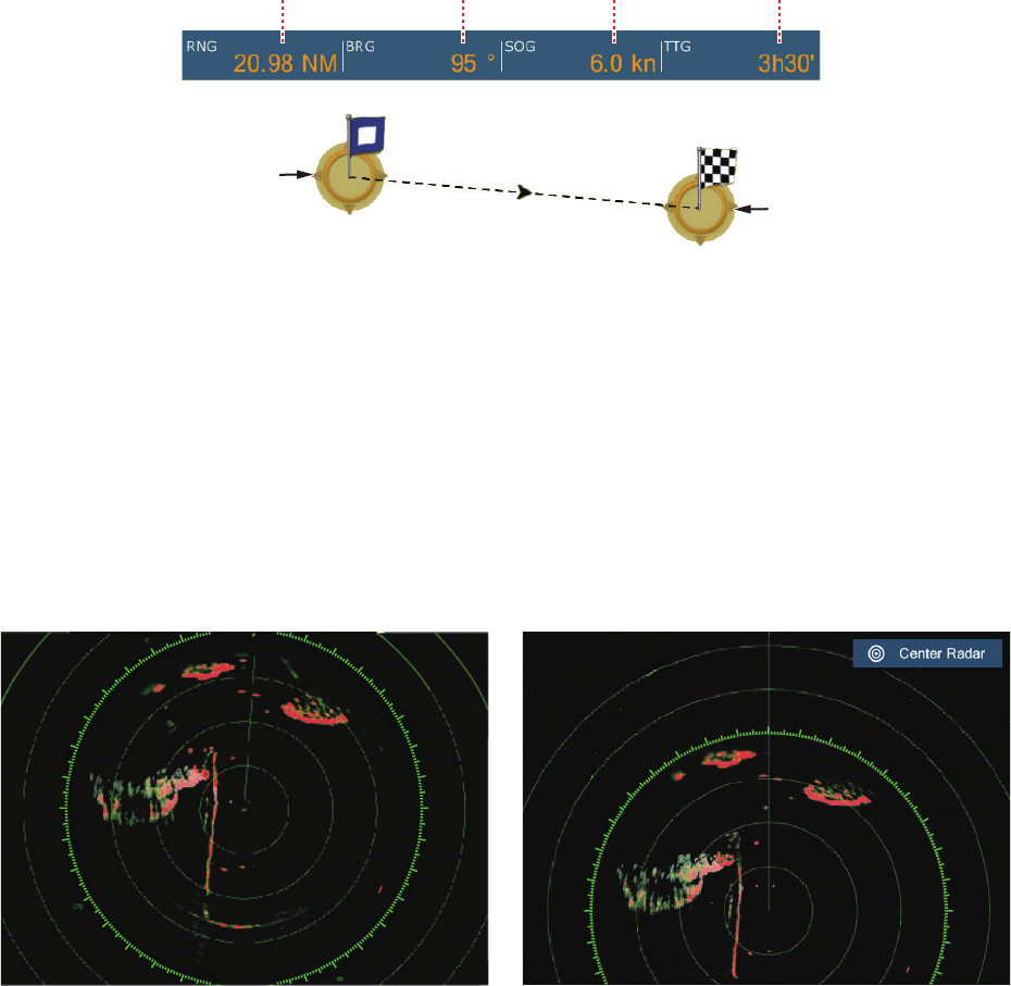
6.9 How to Measure the Range and Bearing Between
Two Targets
You can measure the range and bearing between any two targets with the ruler.
1. Open the slide-out menu then tap [Distance] to display the ruler, which has two
drag-gable circles connected with a line.
2. Drag the circles to set them on the objects for the measurement. The range and
bearing between the objects, SOG and TTG appear at the top of the screen.
3. Tap [Cancel Ruler] at the top right-hand corner of the screen to erase the ruler and
the indication.
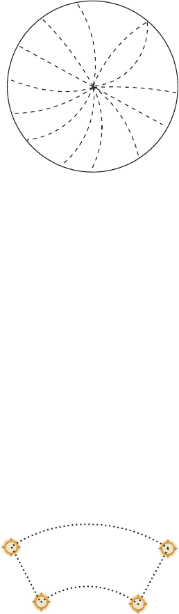
6.10 How to Off-center the Picture
You can off-center your position to expand the view field without selecting a larger
range scale. The position can be off-centered in the bow, stern, port or starboard di-
rection, but not more than 75% of the range in use.
Pan the radar display by dragging with a finger. To return your ship to the center of the
screen, tap [Center Radar] at the top right-hand corner of the screen.
Range Bearing
Speed Over the
Ground TTG
Starting location
2nd location
Normal picture Picture off-centered in stern direction
30
40
50
60
70
80
90
100
110
120
130
140
150
210
220
230
240
250
260
270
280
290
300
310
320
330
010
20
30
40
50
60
70
80
90
100
110
250
260
270
280
290
300
310
320
330
340
350
6. RADAR
6-13
6.11 Heading Line
The heading line indicates your heading in all orientation modes. This line connects
between your position to the outer edge of the radar display. The line is at zero de-
grees on the bearing scale in the head-up mode. The orientation of the line changes
in the north-up mode with the movement of your ship. If it is hard to identify the echoes
on the heading line, you can hide the heading line and range rings for a few seconds.
Open the pop-up menu then tap [Hdg Ln Off] to show or hide the heading line.
6.12 How to Reduce Radar Interference
Radar interference can occur when your ship is near
the radar of another ship that operates on the same fre-
quency band with your radar. The interference shows
on the screen in many bright dots. The dots can be ran-
dom or in the shape of dotted lines that run from the
center to the edge of the screen. You can identify the
interference from the normal echoes, because the in-
terference does not appear in the same location at the
next rotation of the antenna.
Turn off the interference rejector when there is no inter-
ference to prevent the loss of weak targets.
1. Tap the screen then tap [Radar Filters].
2. Turn [Int Reject] on or off as required.
6.13 Guard Zone
The guard zone provides aural and visual alarms against targets (ships, islands, land-
masses, etc.) that enter the area you set.
6.13.1 How to set the guard zone
Note: You can not set the guard zone with the MCU-002. Use the touch operation to
set the guard zone.
1. Open the [Layers] menu.
2. Turn on [Guard Zone 1] or [Guard Zone 2] as re-
quired. A guard zone appears with a circle at each
of its four corners.
3. Drag the circles to set the guard zone.
Note: To set a 360-degree guard zone, set the
same bearing for all four circles.
4. Tap [Done] at the top right-hand corner of the screen to complete the guard zone
and erase the circles.
If you need to readjust a guard zone, tap on a line of the guard zone to show the
pop-up menu then tap [Resize]. Drag the circles to adjust the guard zone. Tap [Done]
at top right corner to finish.
6. RADAR
6-14
6.13.2 How to activate or deactivate the guard zone
1. Tap on a line of the guard zone to show the pop-up menu.
2. Turn [Alarm] on or off as required. The alarm is active when the guard zone lines
are solid and the lines are dashed when the alarm is deactivated.
When a target enters an active zone, the aural alarm sounds (if active), the target
flashes, and the message "TARGET ALARM" flashes in the status bar. Tap the status
bar to silence the aural alarm and stop the flashing message. The message remains
in the status bar and the target continues to flash until the target leaves the guard zone
or the alarm is deactivated.
You can mute the audio alarm by turning off [Alarm Sound] in the [Settings] - [Alarm]
menu. (see paragraph 2.11.6).
6.13.3 How to hide the guard zone
Open the [Layers] menu and turn [Guard Zone 1] or [Guard Zone 2] off as required
The guard zone is erased from the screen.
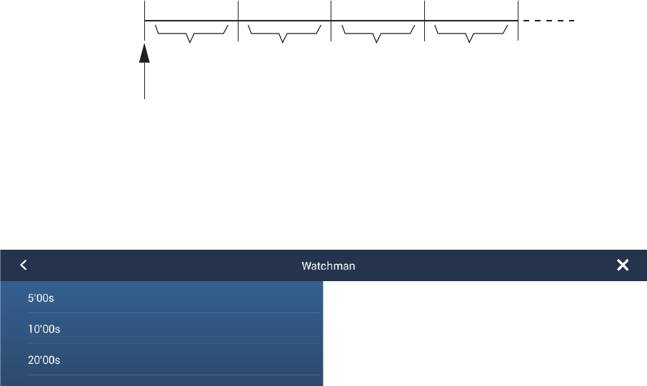
6.14 Watchman
The watchman feature transmits the radar for one minute at a specified time interval
(5, 10 or 20 minutes) to monitor the guard zone. If a target is found in the guard zone,
the watchman is canceled and the radar continues to transmit. This feature helps you
watch for targets in the area you set when you do not continuously require the radar.
1. Set a guard zone. See section 6.13. (Watchman does not operate unless a guard
zone is active. Set Watchman when the radar is in transmit state.)
2. Open the home screen, then tap [Settings] - [Radar].
3. Tap [Watchman].
4. Tap a watchman rest interval.
5. Tap the close button to finish.
6. On the radar display, tap the screen to show the pop-up menu. Turn [Watchman]
on to activate the watchman function.
1 min 1 min
TX TXST-BY ST-BY
Watchman starts
5, 10 or
20 min
5, 10 or
20 min
6. RADAR
6-15
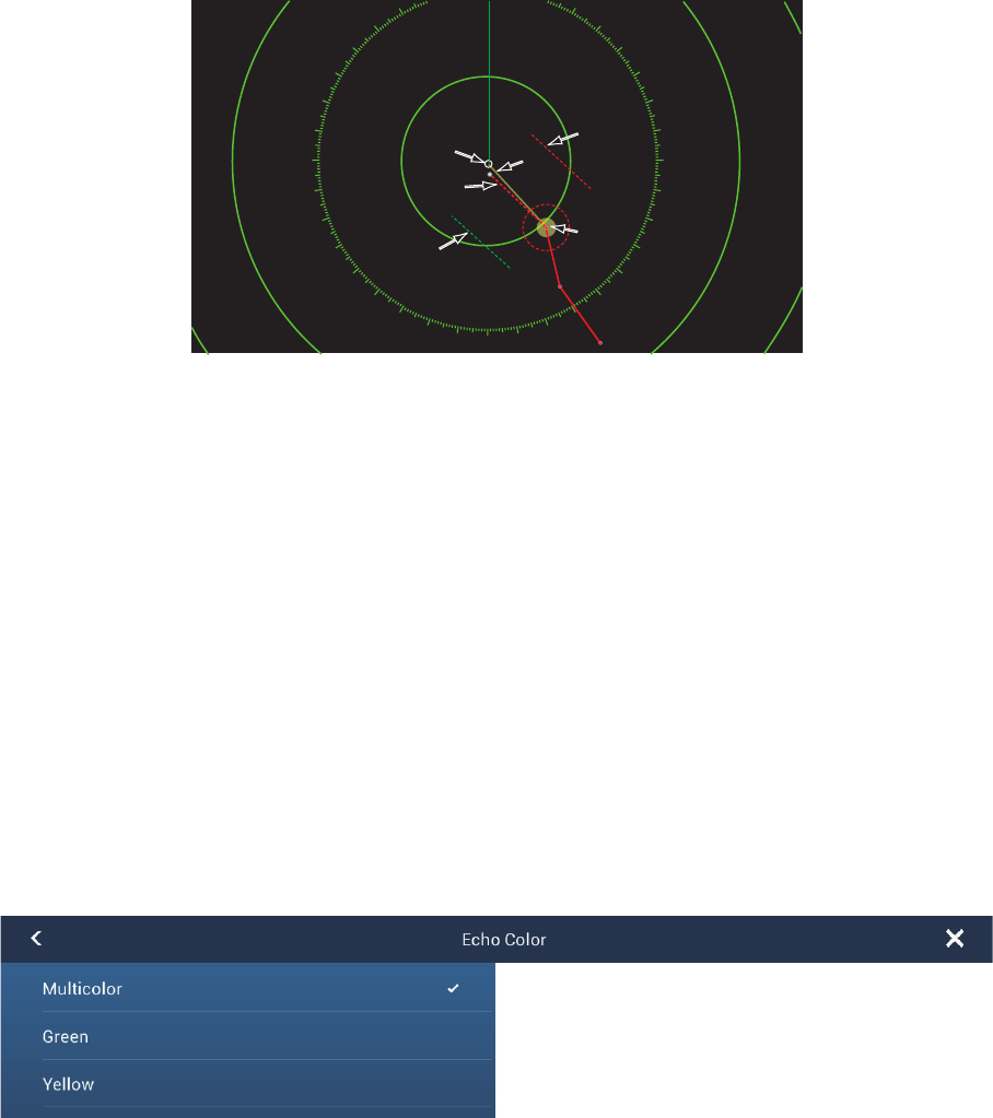
6.15 How to Show, Hide or Cancel an Active Route
You can show, hide the active route on the radar display. Open the [Layers] menu then
turn [Routes] on or off as required.
To cancel route navigation, tap any part of the route then tap [Stop Nav] on the pop-
up menu.
6.16 How to Show or Hide the Own Ship Icon
You can show or hide the boat icon on the radar display.
1. Open the home screen, then tap [Settings] - [Radar].
2. Turn [Own Ship Icon] on or off as required.
3. Tap the close button to finish.
6.17 Echo Color
Echo color is available in colors of green, yellow or multicolor.
1. Open the home screen, then tap [Settings] - [Radar].
2. Tap [Echo Color].
3. Tap a color.
4. Tap the close button to finish.
40
50
60
70
80
90
100
110
120
130
140
150
160
170
180
190
200
210
220
230
240
250
260
270
280
290
300
310
320
1
1
2
3
4
Go to point
Go to point
Your ship
Your ship’
s position
s position
6. RADAR
6-16
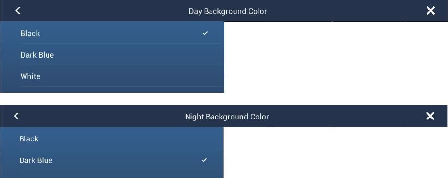
6.18 Background Color
You can select the background color for daytime and nighttime operations.
1. Open the home screen, then tap [Settings] - [Radar].
2. Tap [Day Background Color] or [Night Background Color] menu.
3. Tap a color.
4. Tap the close button to finish.
6.19 Radar Overlay Range Link
The radar overlay range link automatically keeps the display range and radar range in
sync. This feature helps you understand the relation between the radar and the chart.
You can activate or deactivate this feature from the plotter display. See
paragraph 3.2.3.[]
Note: The radar picture can look “out of focus” on long ranges when the range link is
active. This out of focus appearance does not indicate a problem, because it is a char-
acteristic of the digital zoom.
6. RADAR
6-17
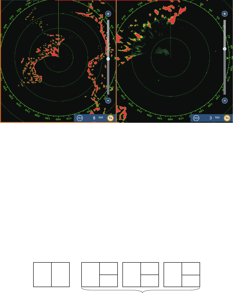
6.20 Dual-Range Display
The dual-range display scans and displays two different radar ranges at the same
time, with a single antenna. There is no time delay between the two pictures and you
have separate control of each picture. This feature lets you keep a close watch on
close-range targets while watching distant targets.
To get the dual-range display, set dual-range displays on the home screen. See
paragraph 1.7.1for the procedure. You can put the dual-range displays in the two-way
and three-way split screens.
The radar functions that are adjusted separately are as follows:
*: The no.1 screen is independent of the no.2 screen when the no.2 screen is in stand-
by. However, when the no.2 screen goes to transmit state, so does the no.1 screen.
• Active route (show or hide) • Gain
• Rain (rain clutter) • Sea (sea clutter)
• Heading line and rings (hide temporarily) • AIS/DSC (show or hide)
• Range • Range rings (show or hide)
• Orientation mode (head-up or north-up) • Trail (clear to restart)
• Auto sea mode ([Advanced] or [Coastal]) • Interference rejector
• Transmission* (Can not set stand-by mode separately)
Short range displayLong range display
Two-way split Three-way split
No.1
screen
No.2
screen
No.1
screen
No.2
screen No.1
screen No.2
screen
No.2
screen
No.1
screen

6. RADAR
6-18
6.21 Radar Menu
This section provides the descriptions for the radar menu items not mentioned earlier.
Radar Initial Setup
[Antenna Rotation]: Starts or stop antenna rotation. For the serviceman. See the in-
stallation manual.
[Antenna Heading Align]: Compensates for error in positioning of the antenna unit
at installation. See the installation manual for the adjustment procedure.
[Main Bang Suppression]: Reduces main bang, the clutter appearing at the screen
center. See the installation manual for the adjustment procedure.
[Enable Sector Blanking]: Sets the area(s) where to prevent transmission. For ex-
ample, set the area where an interfering object at the rear of the antenna would pro-
duce a dead sector (area where no echoes appear) on the display. See the installation
manual for the procedure.
[Antenna Position] items ([Longitudinal (from bow)], [Lateral (-Port)]): Set the posi-
tion of the radar antenna in relation to the bow and port.
Other items
[Antenna Height]: Set the height of the radar antenna above the waterline.
[Auto Tuning]: Activate or deactivate auto tuning.
[Tuning Source]: Selects the radar range for the adjustment, [Range 1] (long range),
[Range 2] ((short range).
[Manual Tuning]: Manually tune.
[Radar Monitoring]: Show various voltage levels, and ARPA data. For the service-
man.
[ARPA Advanced Settings]: Sets ARPA parameters. For the installer, serviceman.
Do not change the settings.
[Set Hardware to Factory Default]: For the serviceman. No use for the user.
[Reset Default Settings]: Restore default settings for items other than those in the
[RADAR INITIAL SETUP] section.
6. RADAR
6-19
6.22 How to Interpret the Radar Display
6.22.1 False echoes
Echo signals can appear on the screen at positions where there is no target or disap-
pear where there are targets. You can identify false targets when you understand why
the false echoes appear. A description of false echoes follows.
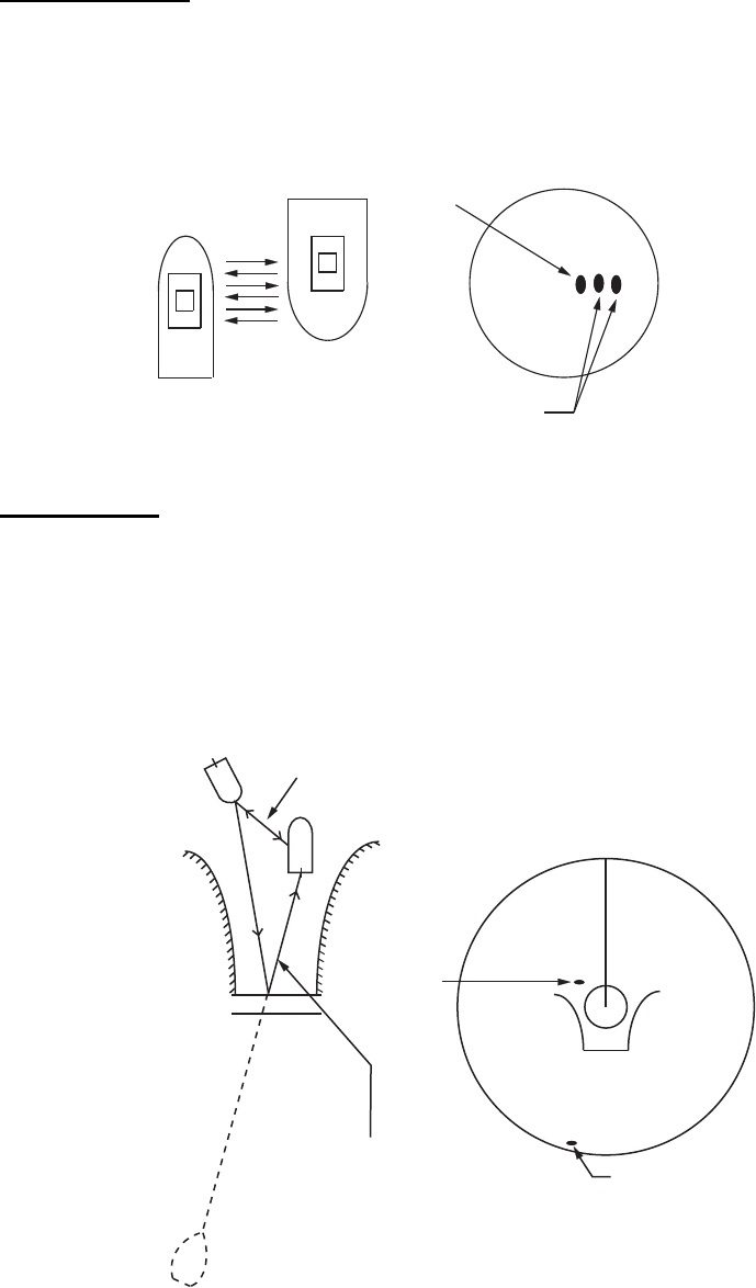
Multiple echoes
Multiple echoes occur when a transmitted pulse returns from a solid object like a large
ship, bridge, or breakwater. A second, a third or more echoes can be seen on the
screen at two, three or more times the true range of the target as shown below. You
can reduce and sometimes remove these multiple echoes if you decrease the gain, or
correctly adjust the sea clutter.
Virtual image
A large target near your ship can show at two positions on the screen. One of the po-
sitions is the true echo reflected by the target. The other position is a false echo which
is caused by the “mirror effect” of a large object on or near your ship. See the figure
shown below for an example of this type of false echo. If your ship gets near a large
metal bridge, for example, a false echo appears on the screen. The echo disappears
after move some distance from the bridge.
Own ship
Target
True
echo
Multiple
echo
Target ship
Your ship
True
echo
False
echo
Mirror image
of target ship
Route for direct reflection
Bridge
Route for
indirect reflection
6. RADAR
6-20
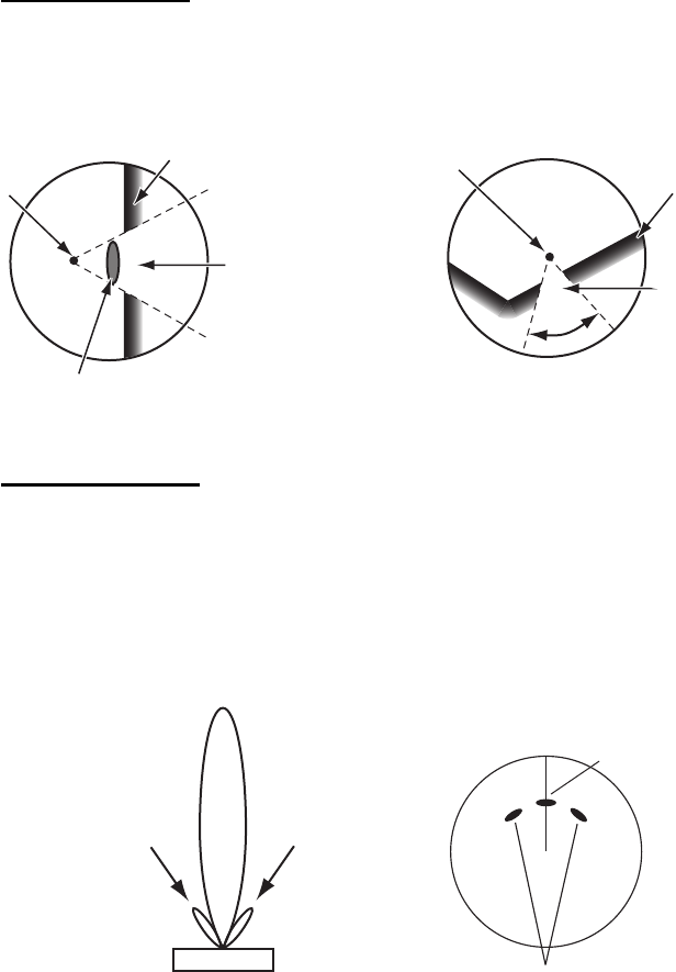
Sector blanking
Funnels, stacks, masts, or derricks in the path of the antenna stop the radar beam. If
the angle opposite the antenna is more than one or two degrees, a sector or shadow
sector appears on the screen. Targets are not displayed within the sector.
Sidelobe echoes
Each time the radar transmits, some radiation leaves on each side of the beam. This
lost energy has the name “sidelobes.” If a target is detected by both the sidelobes and
the mainlobe, the sidelobe echoes can appear at both sides of the true echo at the
same range. Sidelobes normally show only on short ranges and from strong targets.
You can reduce sidelobes if you reduce the gain, or correctly adjust the sea clutter.
Radar position
Large ship
Wharf and its echo
Sector blanking
occurs because
wharf is hidden
behind ship.
Radar position
Wharf and its echo
Sector blanking occurs
because obstruction
(like mast) is in path of
radar beam.
Size of blanking sector depends
on size of obstruction and range.
Mainlobe (beam)
Sidelobe Sidelobe
Antenna
True target
False echoes by sidelobes
6. RADAR
6-21
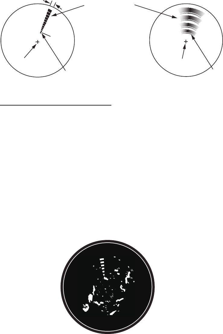
6.22.2 Search and rescue transponder (SART)
A ship in distress uses a radar-SART to show a series of dots on the radar display of
nearby ships to indicate distress. A SART transmits when it receives a radar pulse
from any X-Band (3 cm) radar within a range of approximately 8 nm. When a SART
receives a radar pulse, the SART transmits a response across all the radar frequency
band.
How to detect the SART response
• Use the range scale of 6 or 12 NM. The distance between the SART responses is
approximately 0.6 NM (1125 m) to identify the SART.
• Turn off all the automatic clutter filters.
• Turn off the interference rejector.
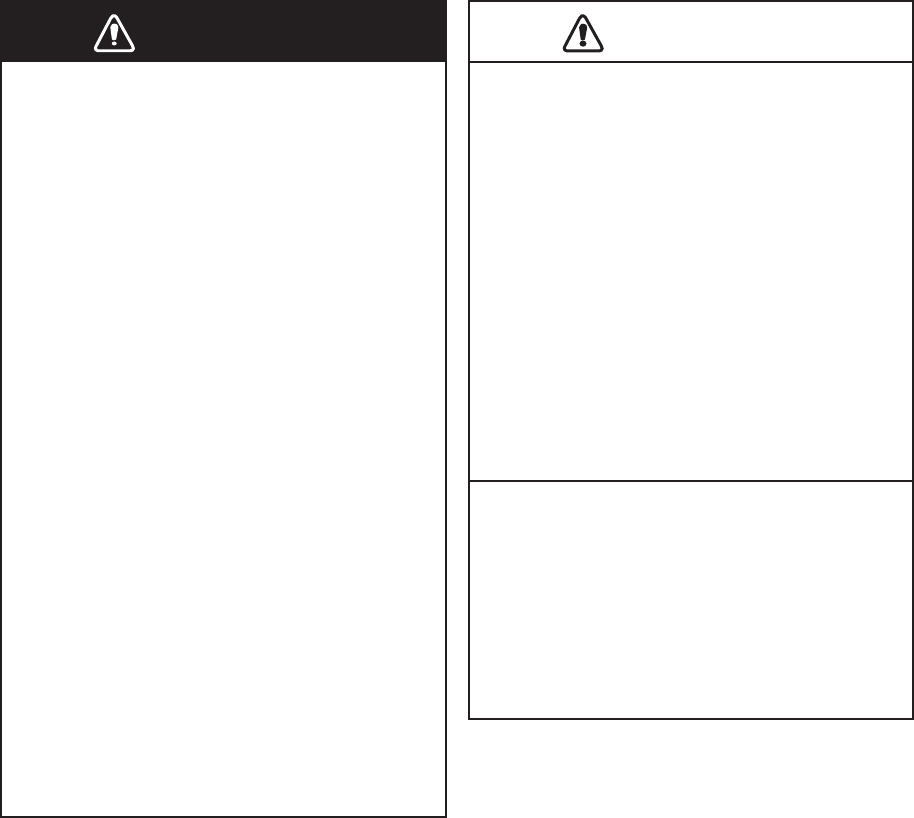
6.22.3 Racon (Radar Beacon)
A racon is a radar transponder that sends a characteristic signal when the racon re-
ceives a radar pulse (normally only the three-centimeter band). If the racon signal is
sent on the same frequency as that of the radar, the signal appears on the radar dis-
play. The racon signal appears on the radar in one of two methods:
• A line that starts just after the position of the Racon
• A Morse code signal displayed with a line just after the position of the Racon
Radar antenna beamwidth
Screen A: When SART is distant Screen B: When SART is close
Position of
SART
24 NM 1.5 NM
Own ship position
Own ship position
Echo from SART
(Lines of 12 dots
are displayed in
concentric arcs.)
Own ship position
Own ship position
Position of
SART
6. RADAR
6-22
6.23 ARPA Operation
The ARPA (Automatic Radar Plotting Aid) shows the movement of a maximum of 30
radar targets. The targets can be acquired manually or automatically. All 30 targets
can be acquired manually when the ARPA acquisition area is not active. If the ARPA
acquisition area is active, that total is equally divided between manual and auto acqui-
sition.
ARPA requires speed and heading data.
6.23.1 How to show or hide the ARPA display
1. Open the [Layers] menu.
2. Turn [ARPA Targets] on or off as required.
WARNING
WARNING
CAUTION
CAUTION
No one navigational aid should be relied
upon for the safety of vessel and crew.
The navigator has the responsibility to
check all aids available to confirm
position. Electronic aids are not a
substitute for basic navigational
principles and common sense.
· This auto plotter automatically tracks an
automatically or manually acquired radar
target and calculates its course and speed,
indicating them by a vector. Since the data
generated by the auto plotter are based on
what radar targets are selected, the radar
must always be optimally tuned for use
with the auto plotter, to ensure required
targets will not be lost or unwanted targets
such as sea returns and noise will not be
acquired and tracked.
· A target does not always mean a
landmass, reef, ships or other surface
vessels but can imply returns from sea
surface and clutter. As the level of clutter
changes with environment, the operator
should properly adjust the Sea, Rain and
Gain to be sure target echoes are not
eliminated from the radar screen.
The plotting accuracy and response of
this auto plotter meets IMO standards.
Tracking accuracy is affected by the
following:
· Tracking accuracy is affected by course
change. One to two minutes is required to
restore vectors to full accuracy after an
abrupt course change. (The actual amount
depends on gyrocompass specifications.)
· The amount of tracking delay is inversely
proportional to the relative speed of the
target. Delay ranges from 15 - 30 seconds
for high relative speed; 30 - 60 seconds for
low relative speed.
Display accuracy is affected by the
following:
· Echo intensity
· Radar transmission pulsewidth
· Radar bearing error
· Gyrocompass error
· Course change (your ship or target)