Furuno USA 9ZWRTR104 Transceiver for Radar Sensor DRS4DL User Manual
Furuno USA Inc Transceiver for Radar Sensor DRS4DL
Contents
- 1. User Manual I
- 2. User Manual II Part 1
- 3. User Manual II Part 2
- 4. User Manual II Part 3
- 5. User Manual II Part 4
- 6. User Manual II Part 5
- 7. User Manual II Part 6
- 8. User Manual II Part 7
- 9. User Manual II Part 8
- 10. User Manual II Part 9
- 11. User Manual II Part 10
- 12. User Manual II Part 11
- 13. User Manual II Part 12
User Manual II Part 11
11. WEATHER
11-9
11.5 Weather Data (NavCenter or Sirius)
The table below shows the weather data available for displaying according to weather
data server (NavCenter or Sirius).
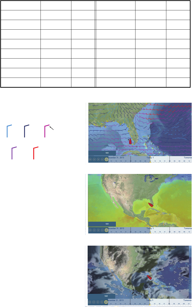
[Wind]: The wind forecast displays
the wind speed by color. The bar at
the top points in the wind direction.
[Waves]: The waves forecast dis-
plays wave height with color. 0 foot
(minimum) is displayed in light blue,
35 feet (maximum) in red.
[Cloud]: The cloud forecast dis-
plays cloud images. 8% of cloud
amount (minimum) is displayed in
white, 100% (maximum) in black.
The cloud amount under 8% is
transparent.
Items NavCenter Sirius Item NavCenter Sirius
Wind Yes Yes Currents Yes No
Waves Yes Yes Altimetry Yes No
SST Yes Yes Plankton Yes No
Cloud Yes No Buoys No Yes
Rain Yes No City No Yes
Pressure Yes Yes Storm No Yes
500mb Yes No Lightning No Yes
Air Temp Yes No Storm Tracks No Yes
1,621
<5 5<, <9
=
9<, <14
=
14<, <19
=
19<
=
Direction
Wind speed
in knot
( )
5.003
4,979
11. WEATHER
11-10
[Rain/Snow]: The rain/snow fore-
cast displays rain/snow images. 0.1
mm/hour of rainfall/snowfall (mini-
mum) is displayed in green, 5 mm/
hour (maximum) in dark violet.
[Air Temp]: The air temp forecast
displays the air temperature by col-
or. -45°C (-49°F) (minimum) is dis-
played in dark violet, 45°C (113°F)
(maximum) is displayed in red.
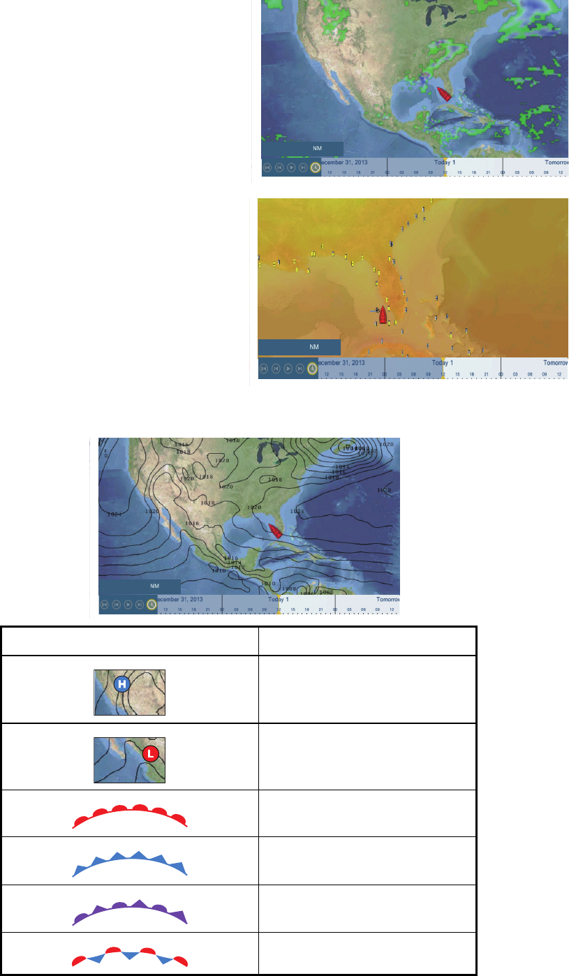
[Pressure]: The pressure forecast displays surface pressure.
Pressure icon Meaning
High pressure
Low pressure
Warm front
Cold front
Occluded front
Stationary front
4,979
1,621
1020
18
1,621
11. WEATHER
11-11
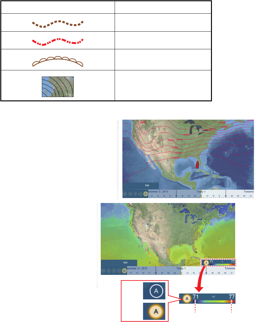
[500mb]: The 500mb forecast dis-
plays the contour lines over 500 mb.
[SST] (Sea surface tempera-
ture): This data layer shows the
temperature of the sea surface
in shades. Lower temperatures
are in dark blue, higher in red.
On the screen, you can turn on
or off the automatic SST scale
with tapping [A].
Set the minimum or maximum
value for which to show SST.
See page 3-5 for how to set the
value. This is available when
[Auto] is off.
Trough
Squall line
Dry line
Isobars
Pressure icon Meaning
1010
980
4,898
4,984
SST scale
You can turn the automatic SST scale adjustment
on or off by tapping the “A”.
OFF: SST can be adjusted manually, with the
range sliders.
ON: SST set according to the depth shading
selection set in the menu.
Minimum
value
ON
OFF
Maximum
value
11. WEATHER
11-12
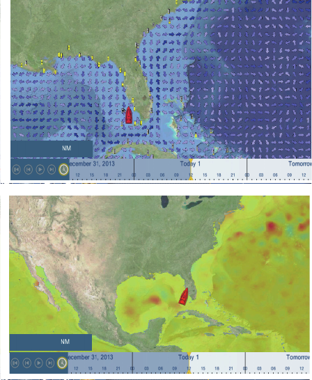
[Currents]: The current forecast dis-
plays the tidal current speed and di-
rection by blue arrow. The darker the
blue, the faster the current speed (0
to 2 kn).
[Altimetry]: The altimetry forecast
displays the sea height anomalies by
color. The large anomalies are dis-
played in red, smaller ones in light
green.
[Plankton]: The plankton forecast displays the plankton growth in tones of green. The
darker the green, the greater the density of plankton.
1,621
3,726
12-1
12. AIS, DSC MESSAGE
12.1 What is AIS?
AIS (Automatic Identification System) is a system that continuously transmits the iden-
tification and position of your ship to AIS-equipped ships within VHF range. All such
ships also receive data from other AIS-equipped ships and display their positions and
other relevant information. The AIS broadcasts this information over a VHF transceiv-
er. Data include:
12.2 How to Show or Hide the AIS Symbols
1. On the radar display or plotter display, open the [Layers] menu.
2. Turn [AIS Targets] on or off as required.
12.3 AIS Target Symbols
• Position • Call sign
• Name of ship • Speed over ground
• Course over ground • Name of position-fixing equipment
• Position of position-fixing equipment • Rate of turn
• Heading
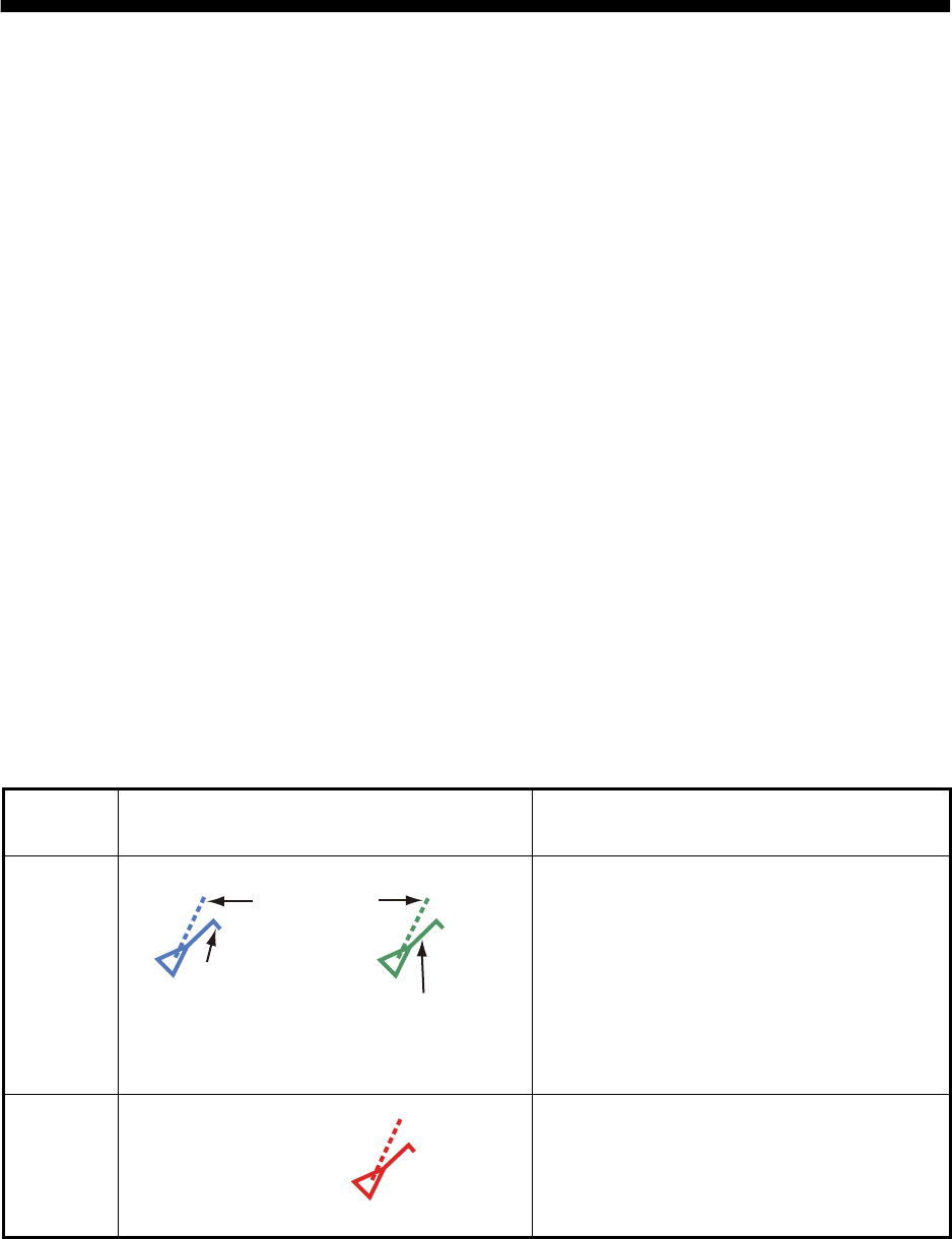
Target
type Symbol Description
Activated
AIS target
COG is indicated on the symbol with a dot-
ted line.
Danger-
ous AIS
target
The target whose values for both CPA and
TCPA are smaller than [CPA Alarm Value]
and [TCPA Alarm Value], which are set in
the [Settings] - [Targets] menu, is indicated
as a dangerous target.
Color: Blue for the Class A AIS
: Green for the Class B AIS
SOG and
COG vector
ROT (Rate of Turn)
Heading line
Color: Red
12. AIS, DSC MESSAGE
12-2
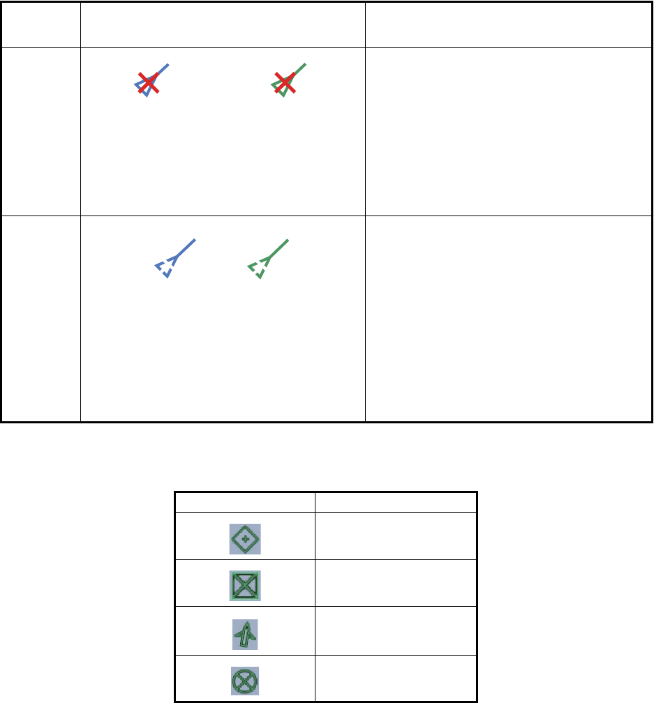
Other AIS symbols that may appear are shown in the table below.
Lost AIS
target
An AIS target becomes a lost target if a
signal is not received from the AIS target
for x* minutes. The lost target symbol is
erased if a signal is not received for an ad-
ditional x* minutes.
*: The time depends on the AIS transpon-
der. Check the operator’s manual for your
AIS transponder for information about lost
targets.
No CPA/
TCPA
target
AIS symbols are shown in a broken lines
in the following cases:
• No water or ground tracking speed of
your ship, or there is no speed data. All
AIS symbols are shown in broken lines.
• No speed data from AIS target. The
symbol of the corresponding AIS target
is shown in broken lines. A target with
neither a reported heading nor COG is
oriented toward the top of the operation-
al display area.
Symbol Meaning
AtoN
Base Station
Aircraft
SART
Target
type Symbol Description
Color
- AIS target: Blue for the Class A AIS
: Green for the Class B AIS
- Cross: Red
Color: Blue for the Class A AIS
: Green for the Class B AIS
12. AIS, DSC MESSAGE
12-3
12.4 Proximity AIS Target Alarm
The proximity AIS target alarm alerts you when an AIS target is within the distance you
specify. When an AIS target is within the distance set, the alarm indication "Proximity
AIS Alarm" flashes in the status bar and the audio alarm sounds. (See
paragraph 2.11.7).
1. Open the home screen, then tap [Settings] - [Targets].
2. Turn on [Proximity AIS Target Alarm].
3. Tap [Proximity AIS Target Alarm Value] to open the software keyboard.
4. Set the alarm value, then tap .
5. Tap the close button to finish.
12.5 How to Ignore Slow Moving AIS Targets
The proximity AIS target alarm may often sound in areas of heavy vessel traffic. You
can prevent frequent release of the alarm against slow, non-threatening targets by
specifying the maximum target speed that triggers the alarm. Any target whose speed
is lower than set here does not trigger the alarm.
1. Open the home screen, then tap [Settings] - [Targets].
2. Tap [Ignore Alarms for AIS Slower than...] to open the software keyboard.
3. Set a speed, then tap . The setting range is 0.0 - 9.9 (knots).
4. Tap the close button to finish.
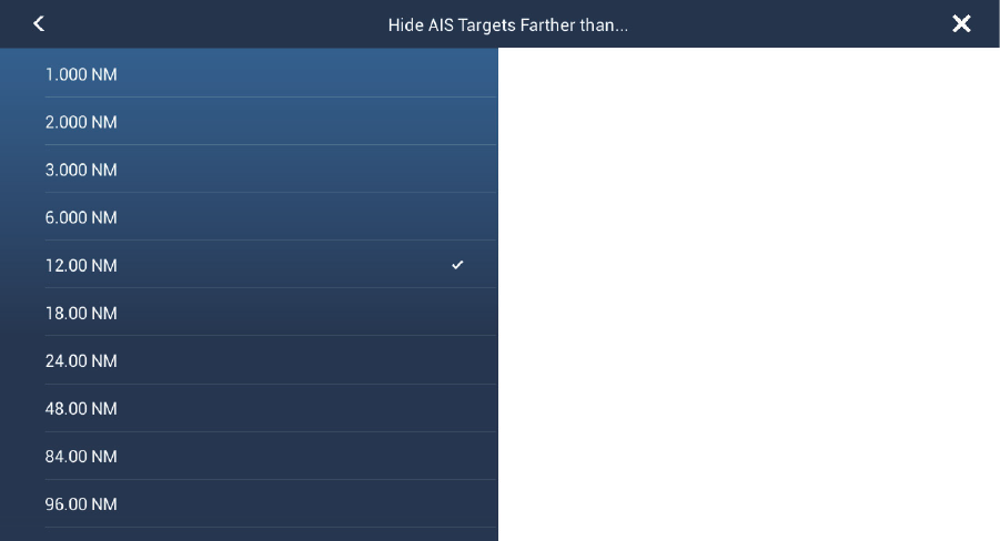
12.6 How to Hide AIS Targets
You can hide the AIS symbols that are beyond the distance you set here.
1. Open the home screen, then tap [Settings] - [Targets].
2. Tap [Hide AIS Targets Farther than...].
12. AIS, DSC MESSAGE
12-4
3. Tap a distance. Targets at a distance greater than selected here are not shown
on the screen.
4. Tap the close button to finish.
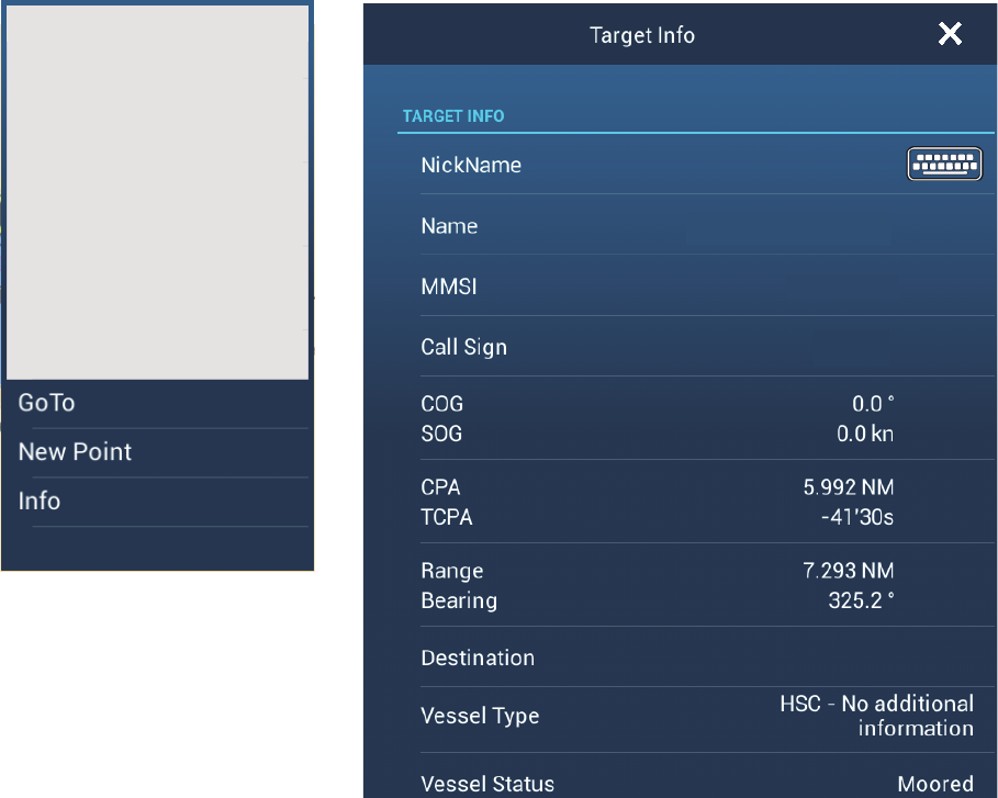
12.7 How to Display AIS Target Data
Tap an AIS target to display the simple information. To get detailed information, tap
the target (plotter or radar display) then tap [Info] on the pop-up menu.
12.8 How to Show or Hide the Target IDs
You can show or hide the target ID of AIS targets.
1. Open the home screen, then tap [Settings] - [Targets].
2. Turn [Display Target IDs] on or off as required.
3. Tap the close button to finish.
Simple information
Detailed information
FURUNO
Name FURUNO
MMSI 124365890
COG 0.0°
SOG 0.0 kn
Range 7.293 NM
Bearing 325.2°
CPA 5.992 NM
TCPA -41’30s
Last Update 30’42s
124365890
ZA1B2
12. AIS, DSC MESSAGE
12-5
12.9 AIS List
How to open the AIS list
1. Open the home screen, then tap [List] and [AIS].
How to display the detailed information for an AIS target
Tap the AIS target on the AIS list then tap [Detail].
AIS
Range/Bearing CPA/TCPA
Range/Bearing CPA/TCPA
Range/Bearing CPA/TCPA
Range/Bearing CPA/TCPA
Range/Bearing CPA/TCPA
CPA
APPARATION
836705890
AMBITIOUS
387650980
AQUAFARER
836705890
BOHEMIAN
180092461
BUTTRESS
180092461
FURUNO
FURUNO
12. AIS, DSC MESSAGE
12-6
How to find an AIS target on the plotter display
Tap the AIS target on the AIS list, then tap [Find On Chart]. The plotter display opens
and the selected AIS target is zoomed in.
How to edit an AIS nickname
1. Tap the AIS target to edit its nickname.
2. Tap [Edit Nickname] to display the software keyboard.
3. Enter the nickname. You can use a maximum of 20 alphanumeric characters.
4. Tap .
5. Tap the close button to finish.
12.10 How to Register an AIS or DSC Target to the
Buddies List
The buddies list provides a quick reference to ships’ MMSI and nickname. For exam-
ple, you might want to enter the MMSI and nickname of partner ships or ships that of-
ten operate in your area.
How to add an MMSI no. to the buddies list
1. Open the home screen, then tap [Settings] - [Targets].
2. Tap [Buddies List (AIS & DSC)].
3. Tap [Add Buddy] to open the numeric software keyboard.
4. Enter the MMSI number, then tap .
5. Tap the MMSI number just entered to show the software keyboard.
6. Enter the nickname, then tap .
7. Tap the close button to finish.
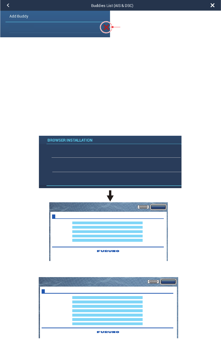
How to delete an entry from the buddies list
1. Open the home screen, then tap [Settings] - [Targets].
2. Tap [Buddies List (AIS & DSC)].
456987321 FURUNO
12. AIS, DSC MESSAGE
12-7
3. Tap the red “X” (to the right of the nickname) of the buddy to delete.
4. You are asked if you are sure to delete the buddy. Tap [OK].
5. Tap the close button to finish.
12.11 AIS Transponder FA-30, FA-50
The FURUNO AIS Transponder FA-30 (or FA-50) installs in the NavNet TZtouch2 net-
work and can be controlled from a NavNet TZtouch2 display. To access the menu for
the transponder, do as shown below. See the respective operator’s manual for details.
1. Connect the FA-30 (or FA-50) to the NavNet TZtouch2 network.
2. Open the home screen, then tap [Settings] - [Initial Setup].
3. Tap [FA30 Browser] or [FA50 Browser].
456987321 FURUNO
Tap to delete
from list.
Close
Initial Setup
Own Vessel Data
Message
Alarm Status
Sensor Status
Tests
For Service
FA-50
Close
Port Setup
Own Vessel Data
Sensor Status
Test
For Service
FA-30
OR
FAX30 Browser
FA30 Browser
FA50 Browser

12. AIS, DSC MESSAGE
12-8
12.12 DSC Message Information
The DSC (Digital Selective Calling) message information feature provides, on the plot-
ter and radar displays, the MMSI no. and position* of the ships that have transmitted
a DSC message to you. A hexagon-shaped marker marks the position of the ship at
the time the DSC was transmitted to you. The marker is color-coded according to the
type of DSC message sent, red for distress and green for non-distress.
* Position at the time of message transmission. Position information is not updated.
This feature requires connection of a DSC capable radiotelephone that outputs the
DSC sentence in NMEA 0183 format.
12.12.1 DSC message notification
When a DSC position report message is received, the message "DSC Position Report
Received" appears in yellow on the status bar at the top of the screen (see
paragraph 2.11.7). To delete the message, tap the status bar.
When a DSC distress message is received, the message "DSC Distress Call Re-
ceived" appears in red on the status bar at the top of the screen. To delete the distress
message, tap the status bar.
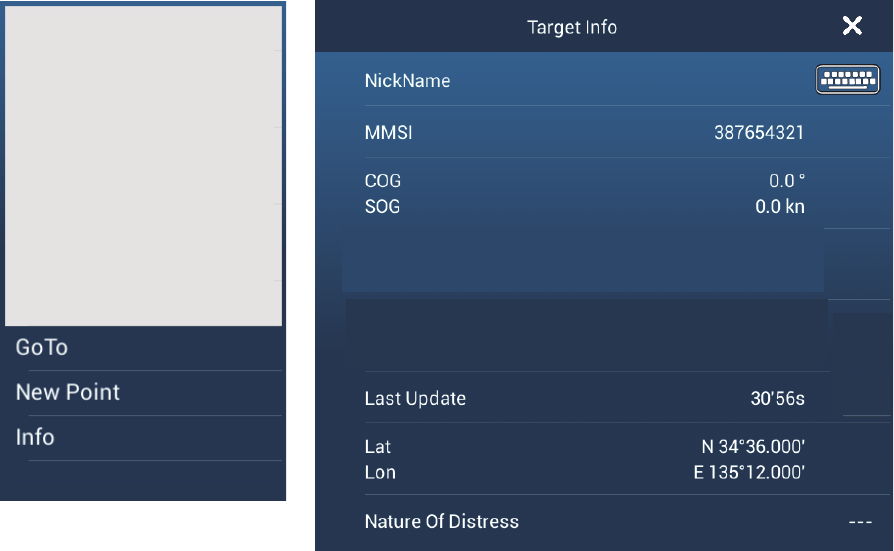
12.12.2 How to go to a DSC point
Tap the DSC marker to go then tap [Go To] on the pop-up menu.
Red: DSC marker for
distress message
Green: DSC marker for
non-distress message
333336789 333335678
MMSI no.
12. AIS, DSC MESSAGE
12-9
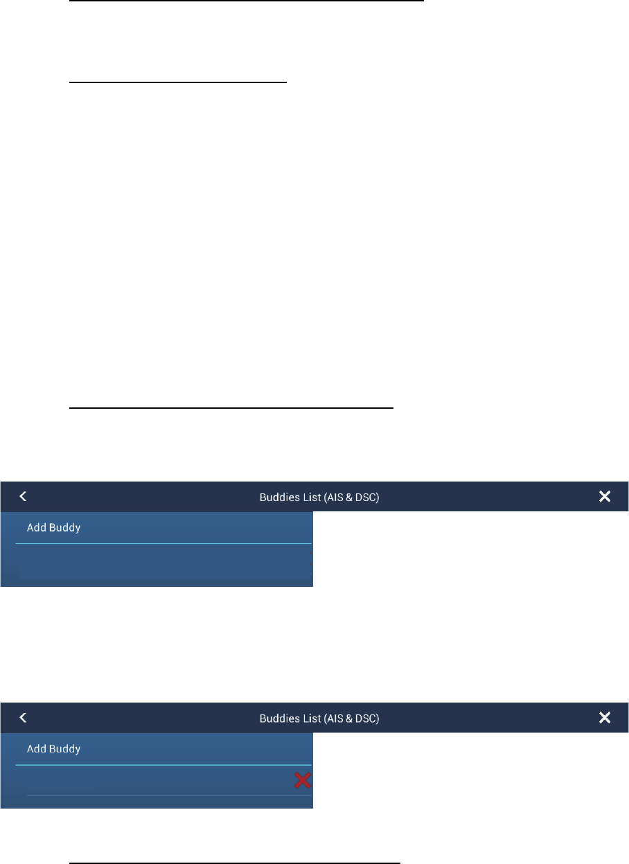
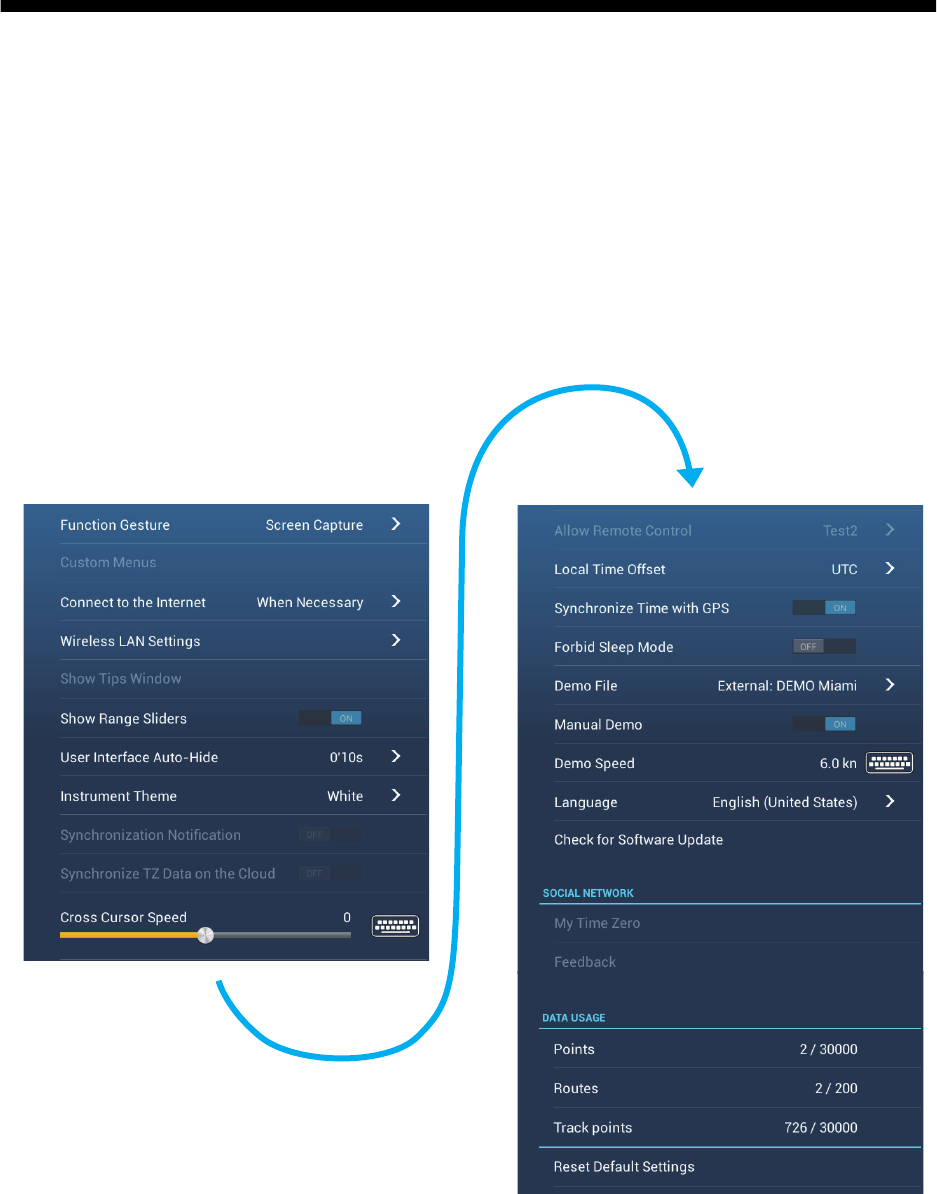
12.12.3 How to display DSC information
Tap a DSC marker to display the simple information (position, MMSI no. of the ship
that transmitted a DSC message, etc.). To get detailed information, tap a DSC marker,
then tap [Info] on the pop-up menu.
Simple information
Detailed information
MMSI 387654321
COG 0.0°
SOG 0.0 kn
Range 7.293 NM
Bearing 325.2°
CPA 5.992 NM
TCPA -41’30s
Last Update 30’42s
CPA 5.992 NM
TCPA 41’30s
Range 7.293 NM
Bearing 325.2°
12. AIS, DSC MESSAGE
12-10
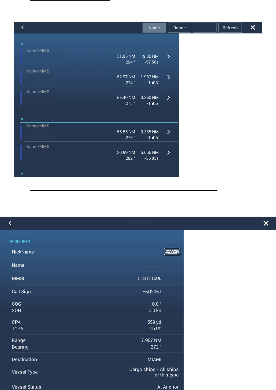
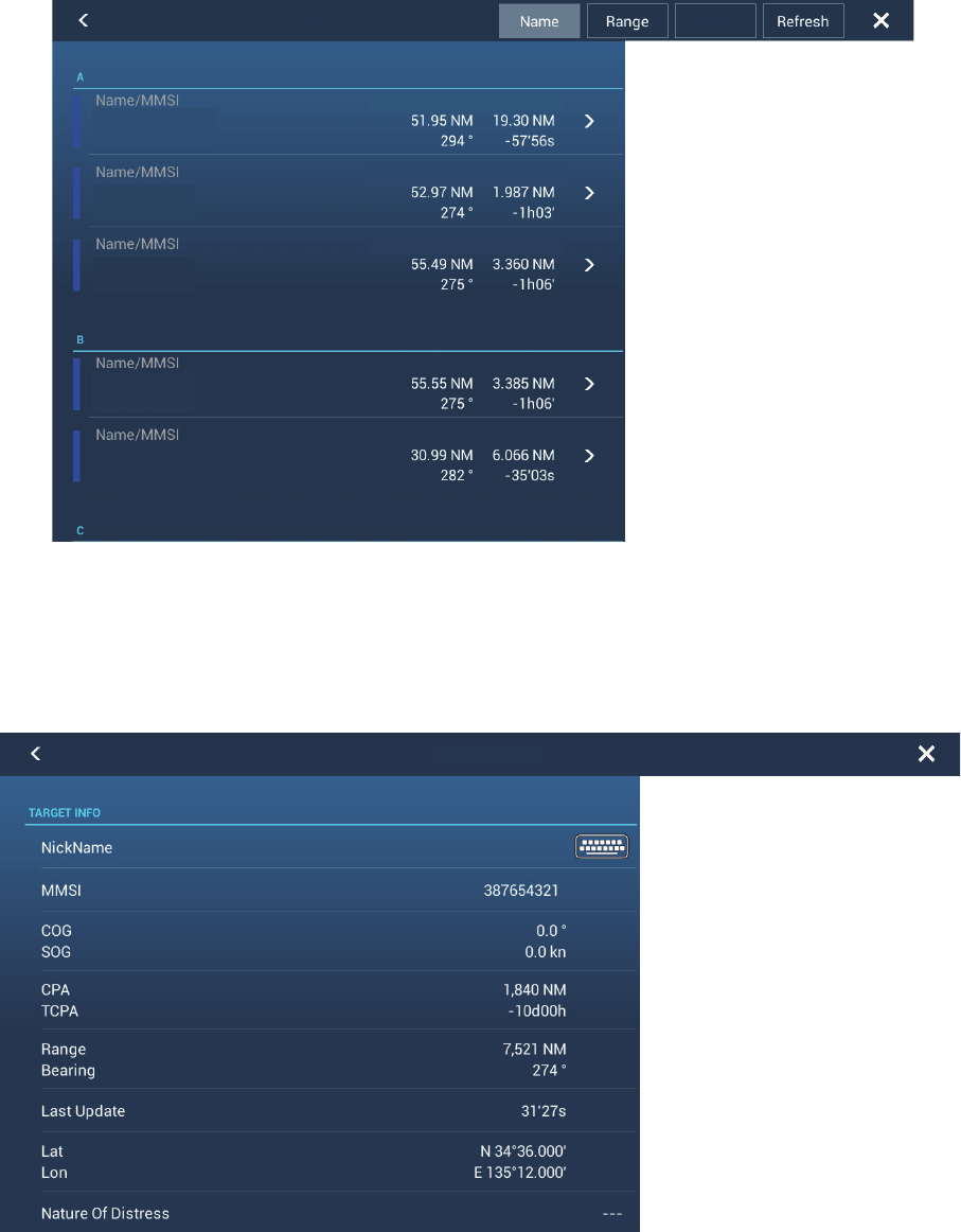
12.12.4 The DSC list
When you receive a DSC message, the message is automatically saved to the DSC
list. To help you quickly identify the DSC target on the plotter and radar displays, you
can replace the MMSI no. indication with the name of your choice; for example, ship’s
name.
1. Open the home screen, then tap [List] - [DSC].
2. Tap [Name], [Range] or [CPA] at the top of the list to sort the list.
[Name]: DSC targets sorted in alphanumeric order.
[Range]: DSC targets sorted by range in ascending order.
[CPA]: DSC targets sorted by CPA in ascending order.
To see the detailed information for a DSC target, tap a DSC then tap [Detail].
To put a DSC marker at the center of the plotter display, tap the DSC target then tap
[Find On Chart].
AIS
Range/Bearing CPA/TCPA
Range/Bearing CPA/TCPA
Range/Bearing CPA/TCPA
Range/Bearing CPA/TCPA
Range/Bearing CPA/TCPA
CPA
APPARATION
836705890
AMBITIOUS
387650980
AQUAFARER
836705890
BOHEMIAN
180092461
BUTTRESS
180092461
387654321
13-1
13. OTHER FUNCTIONS
Once you have become acquainted with your equipment, you can set it according to
your needs. You can change system configuration, change how the equipment oper-
ates and displays information, etc.
The descriptions contained in this section are those not previously mentioned.
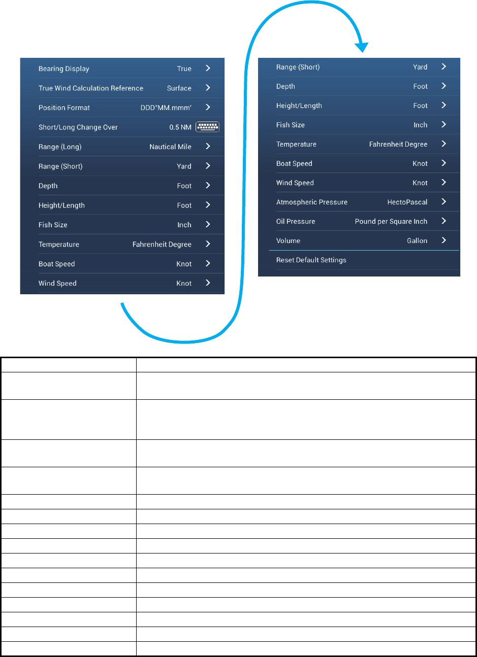
13.1 General Menu
The [General] menu contains items that once preset do not require frequent adjust-
ment.

13. OTHER FUNCTIONS
13-2
[General] menu description
*: In the demo displays, you can move the position for the boat icon to the position
tapped. Tap the screen to open the pop-up menu then tap [Move Boat].
Menu item Function Options
[Show Range
Sliders]
Show or hide the range sliders, which appear at
the right or left edge of the screen depending on
the display mode.
[ON], [OFF]
[User Interface
Auto-Hide]
Select the time to wait before closing a pop-up
menu when no operation is found.
[2 s], [3 s], [5 s], [10 s], [15 s]
[Local Time Off-
set]
Select the time difference between local time and
UTC time.
UTC -12:00 to UTC + 13:00
(at one-hour intervals)
[Synchronize
Time with GPS]
Activate or deactivate synchronizing time with
GPS.
[ON], [OFF]
[Cross Cursor
Speed]
Adjust the cross cursor speed. -7 to +7
[Demo File] Select the demo file to use with the demo mode.
[Manual Demo] Enable or disable the demo mode. [ON], [OFF]
[Demo Speed] Set the ship’s speed to use in the demo mode. 0 to 20 kn
[Check for Soft-
ware Update]
Update the software version. See section 13.5. -
[Reset Default
Settings]
Restore default settings for the [General] menu. -
13. OTHER FUNCTIONS
13-3
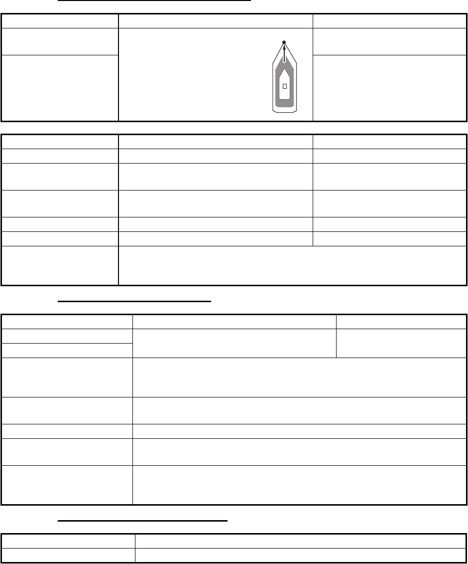
13.2 Units Menu
The [Units] menu sets the unit of measurement for speed, distance, depth, etc.
Menu item Options
[Bearing Display] [Magnetic], [True]
The mode (magnetic or true) of all heading and bearing data.
[True Wind Calculation
Reference]
[Ground], [Surface]
Select wind value to display from speed over ground or speed through
water (surface).
[Position Format] [DDD°MM.mmmm’], [DDD°MM.mmm’], [DDD°MM.mm’],
[DDD°MM’SS.ss”], [DDD.dddddd°]
[Short/Long Change Over] Set the distance at which to change between short and long range. Set
the long range here (0.0 to 2.0 NM)
[Range (Long)] [Nautical Mile], [Kilometer], [Mile]
[Range (Short)] [Foot], [Meter], [Yard]
[Depth] [Foot], [Meter], [Fathom], [Passi Braza]
[Height/Length] [Foot], [Meter]
[Temperature] [Fahrenheit Degree], [Celsius Degree]
[Boat Speed] [Knot], [Kilometer per Hour], [Mile per Hour], [Meter per Second]
[Wind Speed] [Knot], [Kilometer per Hour], [Mile per Hour], [Meter per Second]
[Atmospheric Pressure] [HectoPascal], [Millibar], [Millimeter of Mercury], [Inch of Mercury]
[Oil Pressure] [KiloPascal], [Bar], [Pound per Square Inch]
[Volume] [Gallon] (Gallon & Gallon/Hour), [Litre] (Litre & Litre/Hour)
[Reset Default Settings] Restore default settings for the [Units] menu.
13. OTHER FUNCTIONS
13-4
13.3 Initial Setup Menu
The [Initial Setup] menu, which is mainly for use by the installer of the equipment, sets
up the system according to the sensors connected. These adjustments require some
knowledge of marine electronics equipment. If you are unsure of your abilities, have a
qualified marine electronics technician make the adjustments. Inadequate adjustment
can affect performance.
GPS POSITION section, other items
DATA ACQUISITION section
INTERNAL GPS SETUP section
Menu item Description Options (setting range)
[Longitudinal (from
bow]
Enter the GPS antenna posi-
tioning bow-stern (Longitudi-
nal) and port-starboard
(Lateral) position from the or-
igin.
0 m to 999 m
[Lateral GPS Position
(-Port)]
-99 m to +9 m
Menu item Description Options (setting range)
[Boat Length] Set the length of your boat. 0 m to 999 m
[Size of Static Icon] Set the size of static (such as own ship)
icons.
50 to 150
[Depth Display] Select the start point for depth measure-
ment.
[Under Keel], [Under Sea Lev-
el]
[Transducer Draft] Set the transducer draft. 0.0 m to 99.9 m
[Keel Draft] Set the keel draft. 0.0 m to 99.9 m
[Graphic Instruments
Setup]
Set Min/Max Boat Speed, Min/Max Depth, Min/Max Sea Surface Tem-
perature, Engine(x2) (Max. RPM, Oil Pressure, Temperature), Reset In-
strument Pages, Reset Default Settings.
Menu Item Description Options (setting range)
[GP330B WAAS Mode] Select [ON] to use the WAAS mode for the
corresponding GPS antenna.
[ON], [OFF]
[WS200 WAAS Mode]
[Data Source] Select the source for each data to input to the system. If two or more
sources are connected for a data, select one using the pull-down dialog
box. The FURUNO products are shown at the upper part of the list.
[Sensor List] Show the information for sensors connected to your equipment. Also,
you can set “Nickname” for them here.
[NMEA0183 Output] Select [ON] to output NMEA sentences.
[NMEA 2000 PGN Output] Select [ON] for the PGN's (Parameter Group Number, CAN bus
(NMEA2000) message) to output from the CAN bus port.
[Sky View] Show the condition of GPS and GEO (WAAS) satellites. The bearing
and elevation angle of all GPS and GEO satellites (if applicable) in view
of your receiver appear. For the service technician.
Menu Item Description
[WAAS Mode] Set to [OFF] when using external GPS.
OriginOrigin
13. OTHER FUNCTIONS
13-5
SC-30 SETUP section
CALIBRATION section
DATA DAMPING section
FUSION section
BROWSER INSTALLATION section
Menu item Description Options (setting range)
[WAAS Mode] Select [ON] to use the WAAS mode. [ON], [OFF]
[Heading Offset] Enter the offset value for heading. -180° to +180°
[Pitch Offset] Enter the offset value for pitching. -90° to +90°
[Roll Offset] Enter the offset value for rolling. -90° to +90°
Menu item Description Options (setting range)
[Heading] Offset heading data. -180.0° to +180.0°
[Speed Through
Water]
Calibrate speed data. Enter amount in percentage. -50% to +50%
[Wind Speed] Offset wind speed data. Enter amount in percentage. -50% to ;50%
[Wind Angle] Offset wind angle data. -180° to +180°
[Sea Surface
Temperature]
Offset sea surface temperature data. -10°C to +10°C
Menu item Description Options (setting range)
[COG & SOG] Set data damping time. The lower the set-
ting the faster the response to change.
0 to 59 seconds
[Heading]
[Speed Through Water]
[Wind Speed & Angle]
[Rate of Turn]
Menu item Description Options (setting range)
[Connect to Fu-
sion]
Connect to your Fusion equipment.
[Fusion Auto
Vol7ue]
Set to [ON] to allow this unit to control the Fusion volume.
[Minimum
Speed]
Set the minimum speed threshold. Exceeding this
speed activates volume auto control.
0.0 kn to 19.9 kn
[Maximum
Speed]
Set the maximum speed threshold. 0.1 kn to 99.0 kn
[Volume In-
crease]
Set the amount of extra volume to output. 10% to +50%
Menu item Description Option (setting range)
[FAX30 Browser] Show the Facsimile Receiver FAX-30 display.
[FA30 Browser] Show the AIS Receiver FA-30 display.
[FA50 Browser] Show the AIS Receiver FA-50 display.
13. OTHER FUNCTIONS
13-6
Other items
[GRAPHIC INSTRUMENTS SETUP]
[GRAPHIC INSTRUMENTS SETUP] - [Depth]
[GRAPHIC INSTRUMENTS SETUP] - [Sea Surface Temperature]
[GRAPHIC INSTRUMENTS SETUP] - [Propulsion Engine]
Menu item Description Option (setting range)
[Chart Master Device] Set to ON to set this equipment as the chart master and share one System
ID and chart unlock code in the network.
[System ID] The system ID for this device within the network.
[IP Address] IP address for this unit within the network.
[Quick Self Test] Test the equipment.
[ServiceMan] Requires login password. For the serviceman.
[Event/Buzzer Port
Configuration]
Select from [Event Input] or [Buzzer Input ] to configure information sent to
the port.
[Event Input
Configuration]
Select what data is input as an event.
[Update Network
Equipments]
Update the list of equipment connected to the same network as this unit.
[Reset Default
Settings]
Reset the system to default settings.
Menu Item Description Options (setting range)
Maximum Boat Speed Set the transducer’s maximum detectable
speed
[1 kn] to [99 kn]
Maximum Wind Speed Set the transducer’s maximum detectable
speed
[1 kn] to [99 kn]
Menu Item Description Options (setting range)
Minimum Depth Set the transducer’s minimum detectable
depth
[1 m] to [19 m]
Maximum Depth Set the transducer’s maximum detectable
depth
[20 m] to [2000 m]
Menu Item Description Options (setting range)
Minimum SST Set the transducer’s minimum detectable
temperature
[0.00°C] to [98.99°C]
Maximum SST Set the transducer’s maximum detectable
temperature
[0.01°C] to [99.99°C]
Menu Item Description Options (setting range)
[Max. RPM] Set the maximum rpm of your engine to
show on the RPM display.
[1 rpm] to [20,000 rpm]
[Red Zone Oil Pressure] Set the starting value for the red zone area
of the oil pressure meter.
[0 psi] to [59 kPa]
Max. Oil Pressure Set the maximum oil pressure of your
engine.
[60 psi] to [144 psi]
Min. Temperature Set the minimum temperature for your
engine.
[0.00°C] to [99.00°C]
[Red Zone Temperature] Set the starting value for the red zone area
of the engine temperature indicator.
[0.01°C] to [999.00°C]
13. OTHER FUNCTIONS
13-7
[GRAPHIC INSTRUMENTS SETUP] - [Other Engine]
ENGINE & TANK SETUP
Menu Item Description Options (setting range)
[Max. RPM] Set the maximum rpm of your engine to
show on the RPM display.
[0 rpm] to [20,000 rpm]
[Red Zone Oil Pressure] Set the starting value for the red zone area
of the oil pressure meter.
[0 kPa] to [999 kPa]
Max. Oil Pressure Set the maximum oil pressure of your
engine.
[0 kPa] to [999 kPa]
Min. Temperature Set the minimum temperature for your
engine.
[0°C] to [99°C]
[Red Zone Temperature] Set the starting value for the red zone area
of the engine temperature indicator.
[0°C] to [999°C]
Reset Instrument Pages Resets all instrument pages to default. [OK], [Cancel]
Menu Item Description Options (setting range)
[Nickname] Change the nickname for the engine or tank.
[Used For Propulsion] Select which engine/tank is used to
calculate the distance which may be
traveled using the remaining fuel. [ON] uses
the engine/tank for calculations, [OFF]
ignores the engine/tank.
[ON], [OFF]
[Reset] Resets the engine/tank details to default [OK], [Cancel]
13. OTHER FUNCTIONS
13-8
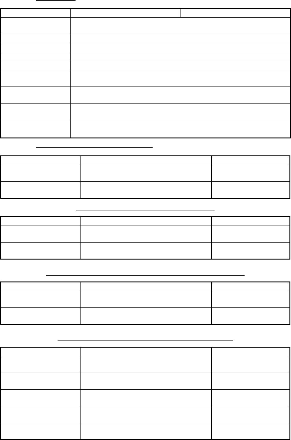
13.4 Facsimile Receiver FAX-30
The FURUNO Facsimile Receiver FAX-30 installs in the NavNet TZtouch2 network
and can be controlled from a NavNet TZtouch2 display. Below are the steps to start
fax operation.
1. Connect the FAX-30 to the NavNet TZtouch2 network.
2. Open the home screen, then tap [Settings] - [Initial Setup].
3. Tap [FAX30 Browser].
4. Tap [WX FAX] or [NAVTEX].
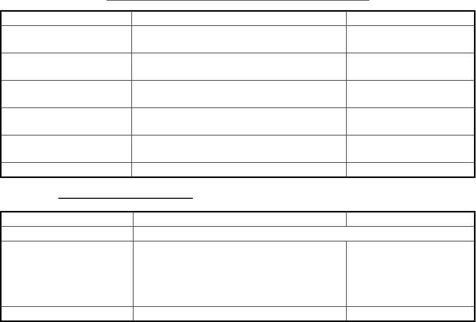
5. Refer to the Operator’s Manual of the FAX-30 for operation information.
The FAX-30 display can only be accessed by one NavNet TZtouch2 unit at a time.
When another NavNet TZtouch2 display accesses the FAX-30, control of the FAX-30
is given to that display after the picture has stopped completely. This sequence takes
approximately one minute.
FAXSIMILE RECEIVER
FAX-30
WX FAX
NAVTEX
LOGOUT
FAX30 Browser
FA30 Browser
FA50 Browser
MENU
100N JMH 3622.5kHz
XXXrpm
SN=11
SS=55
IOCXXX
STBY
CHANNEL SETUP
TIMER SETUP
EDIT STATION LIST
SYSTEM SETUP
RX MODE
<< Top
NEXT PAGE 1
/
2