Furuno USA 9ZWRTR104 Transceiver for Radar Sensor DRS4DL User Manual
Furuno USA Inc Transceiver for Radar Sensor DRS4DL
Contents
- 1. User Manual I
- 2. User Manual II Part 1
- 3. User Manual II Part 2
- 4. User Manual II Part 3
- 5. User Manual II Part 4
- 6. User Manual II Part 5
- 7. User Manual II Part 6
- 8. User Manual II Part 7
- 9. User Manual II Part 8
- 10. User Manual II Part 9
- 11. User Manual II Part 10
- 12. User Manual II Part 11
- 13. User Manual II Part 12
User Manual II Part 9
7. FISH FINDER (SOUNDER)
7-16
7.12 How to Enter an Event Mark, Go to an Event Mark
or a Position
You can put an event mark (at own ship position) on the sounder display. The point
also appears on the plotter display. You can set an event mark or a position as a go
to point.
How to enter an event mark
1. Tap the screen at the location where to put an event mark (for exam-
ple, on a fish symbol), then tap [New Point]
2. Tap an event mark. In the right example, a crab mark is put on a fish
symbol.
How to go to an event mark or a position
1. Tap a fish symbol (only in ACCU-FISH™ mode), event mark or a position to dis-
play the pop-up menu.
2. Tap [GoTo]. The selected symbol*, event mark* or position is highlighted on the
plotter display. For details, see section 4.11.
*: When [ACCU-FISH] is turned on from the pop-up menu.
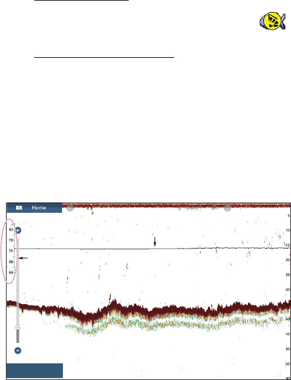
7.13 Temperature Graph
With water temperature data, you can plot sea surface temperature over time. Open
the pop-up menu and turn on [Temperature]. The temperature graph runs across the
screen from right to left. The temperature scale is at the left edge of the display. The
unit of measurement (°C or °F) can be selected with [Temperature] in the [Units]
menu.
294 ft
Temperature graph
Temperature scale
ft HF 37.1
7. FISH FINDER (SOUNDER)
7-17
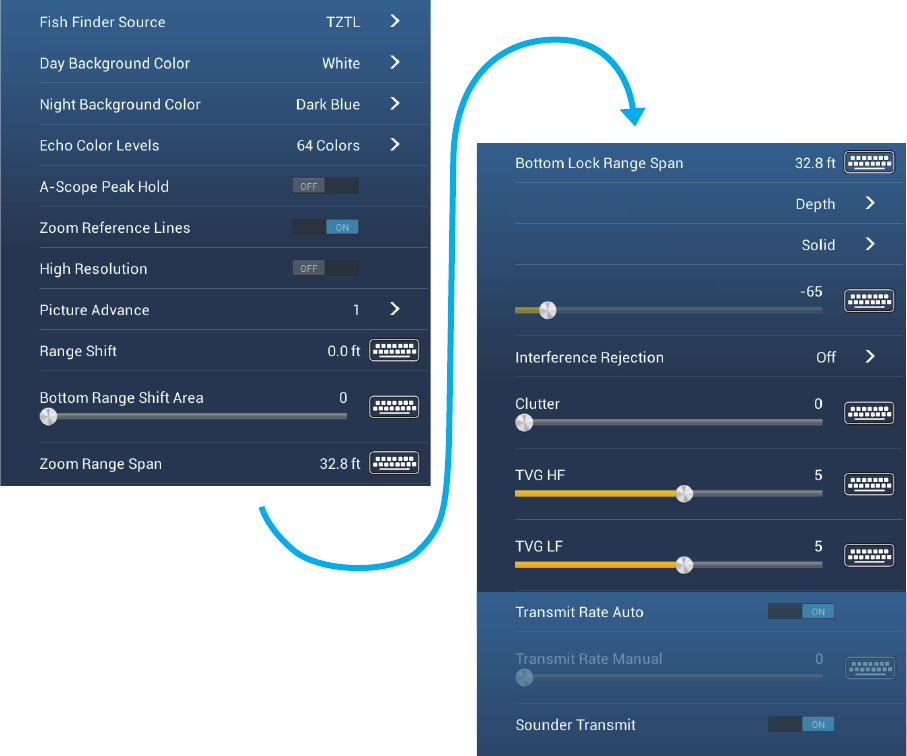
7.14 Sounder Menu
This section describes the fish finder functions not described in previous sections.
Open the home screen, then tap [Settings] - [Sounder].
[Day Background Color]: Select the background color for use during daylight hours.
The options are [White], [Light Blue], [Black] and [Dark Blue].
[Night Background Color]: Select the background color for use at nighttime. The op-
tions are [Black] and [Dark Blue].
[Echo Color Levels]: Select the number of colors shown on the screen. The selec-
tions are [8 Colors], [16 Colors] and [64 Colors].
[Zoom Reference Lines]: Show or hide the zoom marker, which appears in the bot-
tom lock and bottom zoom modes.
[High Resolution]: When you select [OFF], smoothed echoes are displayed, howev-
er, the screen resolution is lower. To get higher screen resolution and greater detail,
select [ON].
[Bottom Range Shift Area]: Select the area where to show the bottom echo, when
[Auto Range] is active. For example, setting 75% would place the bottom echo at a
position equivalent to 75% from the top of the screen.
ACCU-FISH Info
ACCU-FISH Symbols
ACCU-FISH Size Correction
7. FISH FINDER (SOUNDER)
7-18
[Heaving Correction]: When the ship is in rough seas, the bottom echo and the
echoes from fish are not stable, because the distance to the bottom changes. To re-
move this problem, the satellite compass sends pitch and roll data to the fish finder to
adjust the TX and RX beams. This function requires a FURUNO Satellite Compass.
Not applicable to the internal sounder.
[Transmit Rate Auto]: Automatically set the transmit rate according to ship’s speed,
and is inoperative when there is no speed data.
[Transmit Rate Manual]: Change the TX pulse repetition rate in 21 levels (21 is high-
est power.). Use 20 in normal use. Lower the TX rate in shallow waters to prevent the
second reflection echo.
[Sounder Transmit]: Turn on or off the sounder transmission.
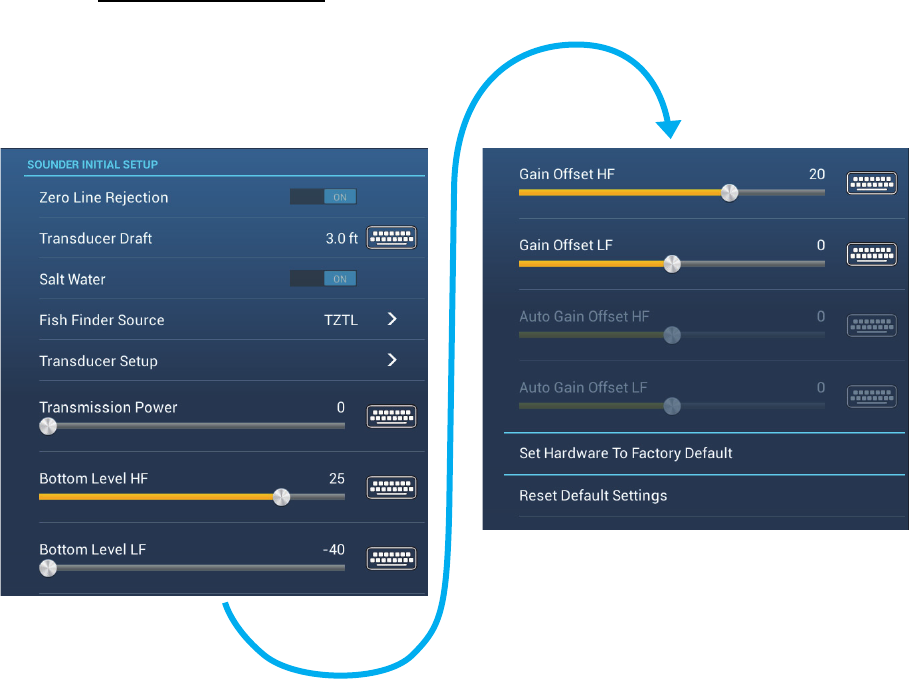
Sounder initial setup
[Zero Line Rejection]: Turn the zero line (transmission line) on or off. When turned
on, the transmission line disappears, which allows you to better watch fish echoes
near the surface. The length of the transmission line changes with transducer used
and installation characteristics.
[Transducer Draft]: Set the distance between the transducer and the draft line to
show the distance from the sea surface (Setting range: 0.0 to 99.9 ft).
[Salt Water]: Select [ON] to use this equipment in salt water.
[Fish Finder Source]: Select the sounder used, among DFF1, BBDS1, DFF3, FCV-
1150 or DFF1-UHD.
7. FISH FINDER (SOUNDER)
7-19
[Transducer Setup]: Select the method to setup the transducer, manually or by se-
lecting the model number.
[Manual]: Enter high/low frequencies and TX power.
[Model Number]: Select the type of the transducer connected.
[Transmission Power]: Interference can appear on the screen when the fish finder
on your ship and another ship have the same TX frequency. To prevent this interfer-
ence, lower your TX power and ask the other ship to lower their TX power. (Internal
sounder and external sounder other than DFF1-UHD)
[External KP]: Turn on to sync with external keying pulse. (For external sounder)
[Bottom Level HF (LF)]: The default bottom level setting (0) determines that two
strong echoes received in sequence are bottom echoes. If the depth indication is not
stable in the default setting, adjust the bottom level here. (For Internal, external sound-
er.)
[Gain Offset HF (LF)]: If the gain setting is wrong, or there is a difference in the gain
between the low and high frequencies, you can balance the gain for the two frequen-
cies here. (For internal, external sounder)
[Auto Gain Offset HF (LF)]: If the auto gain offset is wrong, or there is a difference in
the gain between the low and high frequencies, set an offset here to balance auto gain
for the two frequencies. (For internal, external sounder)
[STC HF (LF)]: Delete unnecessary echoes (plankton, air bubbles, etc.) near the sur-
face that hide the fish near the surface. The setting range is 0 to 10, and 0 is off. 10
deletes unnecessary echoes from the surface to approximately 16 ft. Make sure you
do not use more STC than necessary, because you can erase the small echoes near
the surface. (For DFF3, DFF1-UHD)
[Frequency Adjust HF (LF)]: You can adjust the TX frequency of both the low- and
high-frequency transducers. Use this feature when your fish finder and another fish
finder operate on the same frequency, causing interference. Change the frequency of
your transducer by enough percentage points to remove the interference. (For DFF3)
[TX Pulse HF (LF)]: The pulse length is automatically set according to range and
shift.Use a short pulse for better resolution and a long pulse when detection range is
important. To improve resolution on zoom displays, use [Short 1] or [Short 2]. [Short
1) improves the detection resolution, but the detection range is shorter than with [Std]
(pulse length is 1/4 of [Std]). [Short 2] raises the detection resolution, however detec-
tion range is shorter (pulse length is about 1/2 of [Std]) than [Std]. [Std] is the standard
pulse length, and is suitable for general use. [Long] increases the detection range but
lowers the resolution (about 1/2 compared to the [Std] pulse length). (For DFF3)
[Rx Band HF (LF)]: The RX bandwidth is automatically set according to pulse
length.To decrease noise, select [Narrow]. For better resolution, select [Wide]. (For
DFF3)
[Temperature Port]: Select the data source for water temperature. (For DFF3, DFF1-
UHD)
[MJ]: The water temperature data from the water temperature/speed sensor
[Low Frequency]: The low frequency measured water temperature
[High Frequency]: The high frequency measured water temperature
7. FISH FINDER (SOUNDER)
7-20
[Set Hardware to Factory Default]: Select this menu item to restore default settings
for the unit selected in [Fish Finder Source]. (External sounder only)
[Reset Default Settings]: Select this menu item to restore default settings for the
[Sounder] menu.
7.15 Interpreting the Display
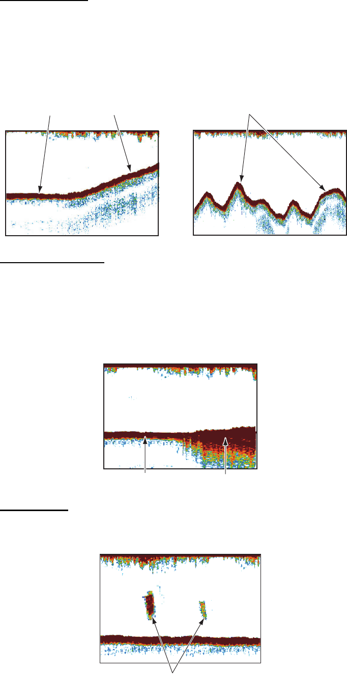
Zero line
The zero line (transmission line) shows the position of the transducer. The line disap-
pears from the screen when the range is shifted.
Bottom echoes
The strongest echoes are from the bottom, and are normally shown in reddish-brown
or red. The colors and the width change with bottom material, depth, sea condition,
installation, frequency, pulse length and sensitivity.
Zero
line
Range shifted
Second
bottom echo
Difference in sensitivity
Difference in depth
7. FISH FINDER (SOUNDER)
7-21
Bottom contour
The tail from a hard bottom is longer than the tail from a soft bottom, because the hard
bottom reflects more of the ultrasonic pulse. An echo from shallow water gives a stron-
ger reflection than the echo received from deep water. A longer bottom tail appears
on slopes, because of the difference in travel time at both edges of the beam angle.
For the rough bottom, echoes are reflected on many different planes, which displays
echoes in many layers, giving a 3D effect.
Nature of a bottom
The nature of a bottom is known from the intensity and length of the bottom tail. To
find the nature of a bottom, use a long pulse length and normal gain. For the hard and
rough bottom, the bottom echo is reddish-brown with a long tail. For the mud or sand
bottom, the bottom echo has less red and with a short tail. A bottom with a lot of small
particles can give a long tail on the low frequency picture.
Fish volume
The size and density of a school of fish are indicators of the quantity of fish.
Soft bottom Hard bottom Rough bottom
Rock base
Mud & sand
Large school
Large school
Small school
Small school
Size of school of fish
7. FISH FINDER (SOUNDER)
7-22
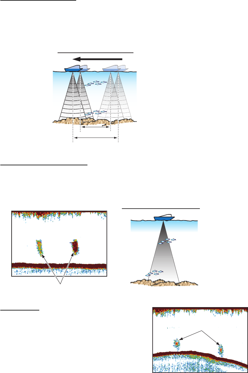
Size of a school of fish
Usually the size of fish echoes on the screen is proportional to the actual size of the
school of fish. However, if two fish echoes appear at different depths with the same
size, the school of fish at the shallower depth is larger because the ultrasonic beam
widens as it propagates and a school of fish in deep water is displayed larger.
Density of a school of fish
If two schools appear with the same color at different depths, the one in deeper water
is denser because the ultrasonic wave attenuates as it propagates and the school of
fish in deep water tends to be displayed in a weaker color.
Bottom fish
The echoes from the bottom are stronger than the
bottom fish echoes so that you can distinguish be-
tween them by colors. The bottom echoes are
normally shown in reddish-brown or red, the bot-
tom fish echoes in weaker color.
Sounding time for a deep school of fish
p
school
o
e for a deep
e
f
or
S
g
S
o
un
di
ng
tim
e
Sounding time for a shallow school of fish
Sounding time for a shallow school of fish
School depth and sounding time
Fish echo
Weak echo
Less reddish
(Sparse echo)
Reddish
(Dense echo)
a
k
ec
h
o
o
Strong echo
Difference in signal strength
Bottom fish echo
7. FISH FINDER (SOUNDER)
7-23
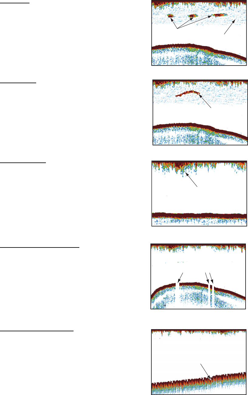
Plankton
A plankton layer appears as a large amount of
green or blue dots, and is a possible location for
fish. A plankton layer moves down in the day and
up at night.
Current rip
When two ocean currents of different speeds di-
rections and water temperatures meet, a current
rip occurs. A current rip appears on the screen as
shown in the right illustration.
Surface noise
When the sea is rough or the ship moves over a
wake, surface noise can appear at the top of the
screen.
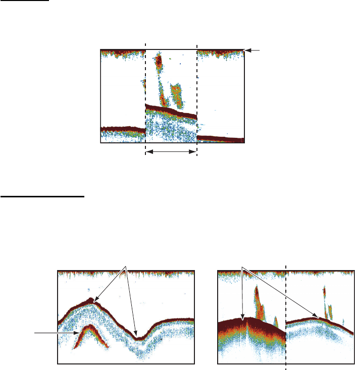
Air bubbles in the water
When the sea is rough or the ship makes a quick
turn, there can be blank spots in the bottom echo
(see the right illustration). These blank spots are
caused by air bubbles which stop the movement
of the sound wave. These air bubbles can occur
with the low frequency ultrasonic waves.
Unstable bottom echo
The bottom echoes can have a saw-tooth appear-
ance. This occurs in heavy weather because pitch-
ing and rolling changes the direction of the
ultrasonic pulses and the vertical motion of the
ship causes the distance to the bottom to change.
Plankton
School of fish
Current rip
Surface noise
Ultrasonic wave
blocked by air bubbles
Unstable bottom echo
7. FISH FINDER (SOUNDER)
7-24
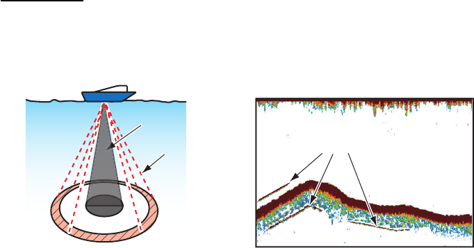
False echo
When an ultrasonic pulse is transmitted, some energy leaves from each side of the
beam. This energy has the name “sidelobe”. Echoes from sidelobes show on the
screen as false images like in the illustration shown below.
Mainlobe
Mainlobe
Sidelobe
Sidelobe False image
8-1
8. FILE OPERATIONS
Points and routes can be imported and exported and track can be exported, using mi-
cro SD cards (w/SD card unit) or USB flash drive. (The card drive at the rear of the
display unit is for chart cards.)
Note: DO NOT remove an SD card while it is being accessed, to prevent loss of data
or damage to the card.
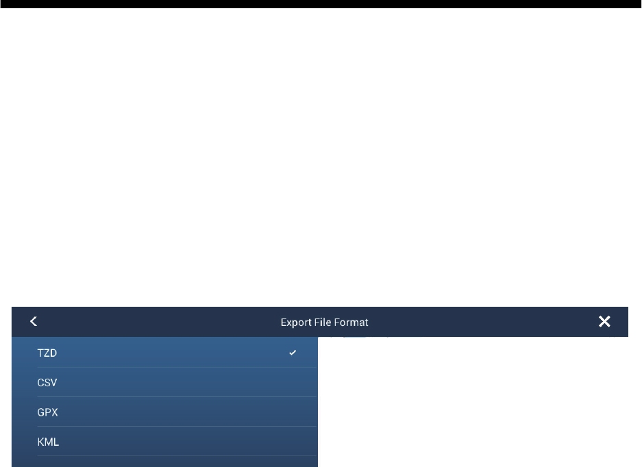
8.1 File Format
You can select the file format to use to export data.
1. Open the home screen, then tap [Settings] - [Files].
2. Tap [Export File Format].
3. Tap [TZD], [CSV], [GPX] or [KML].
[TZD]: For NavNet TZtouch2
[CSV]*: For use with NavNet 3D
[GPX]: For use with PC plotter
[KML]: For use with PC plotter
* The CSV format has the following export restrictions:
- 2000 points maximum
- 200 routes (100 points per route) maximum
- 10000 track points maximum
4. Tap the close button to finish.
8. FILE OPERATIONS
8-2
8.2 How to Export Points and Routes
When the capacity for point is reached, the oldest point is erased to clear space for
new point. A new route cannot be entered when the memory for routes is full. If you
need to save points and routes permanently, save them to a micro SD card.
1. Put a formatted micro SD card in the right hand card slot in the SD card unit.
2. Open the home screen, then tap [Settings] - [Files].
3. Tap [Export All Points & Routes].
4. Tap [SDCardRight].
5. You are asked if you are sure to export points and routes. Tap [OK].
6. The message "EXPORT SUCCEEDED" appears if the exporting was successful.
Tap [OK] to finish.
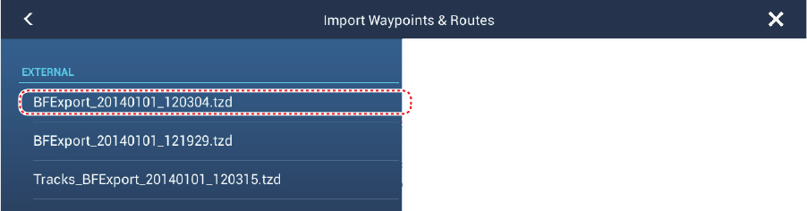
8.3 How to Import Points and Routes
You can import points and routes to the internal memory of a NavNet TZtouch2 unit.
1. Put the correct micro SD card in the SD card unit.
2. Open the home screen, then tap [Settings] - [Files].
3. Tap [Import Points & Routes]. A list of files stored on the SD card appear.
4. Tap the points and routes file to import. You are asked if you are sure to import
points and routes. Tap [OK].
5. The message "IMPORT SUCCEEDED" appears if the importing was successful.
Tap [OK] to finish.
Points and routes file
8. FILE OPERATIONS
8-3
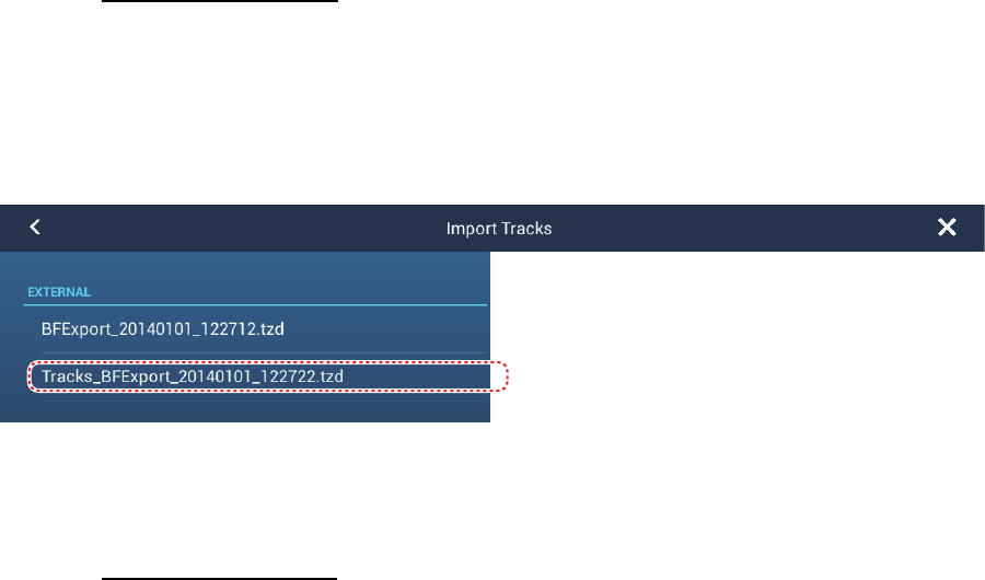
8.4 How to Import or Export Track
How to import track
You can import tracks to the internal memory of a NavNet TZtouch2 unit.
1. Put the correct micro SD card in the SD card unit.
2. Open the home screen, then tap [Settings] - [Files].
3. Tap [Import Tracks]. A list of files stored on the SD card appears. Tap a tracks file.
4. You are asked if you are sure to import tracks. Tap [OK].
5. The message "IMPORT SUCCEEDED" appears if the importing was successful.
Tap [OK] to finish.
How to export track
You can export tracks to a micro SD card.
1. Put a blank formatted micro SD card in the SD card unit.
2. Open the home screen, then tap [Settings] - [Files].
3. Tap [SDCardRightl].
4. You are asked if you are sure to export tracks. Tap [OK].
5. The message "EXPORT SUCCEEDED" appears if the exporting was successful.
Tap [OK] to finish.
8.5 How to Backup the Equipment Settings
You can save the settings to a micro SD card to use the settings on other NavNet
TZtouch2 units.
1. Put a blank formatted micro SD card in the SD card unit.
2. Open the home screen, then tap [Settings] - [Files].
3. Tap [BackUp Settings].
4. Tap [SDCardRight]
The message "EXPORT SUCCEEDED" appears if the exporting was successful. Tap
[OK] to finish.
Tracks file
Tracks file
8. FILE OPERATIONS
8-4
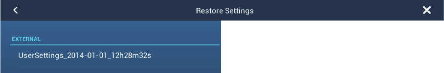
8.6 How to Load the Equipment Settings
You can load the saved settings in a micro SD card to this unit.
1. Put the correct micro SD card in the SD card unit.
2. Open the home screen, then tap [Settings] - [Files].
3. Tap [Restore Settings].
4. Tap [SDCardRight]. A list of user settings appears. Tap a user settings file.
5. You are asked if you are sure to restore settings. Tap [OK].
6. The message "IMPORT SUCCEEDED" appears if the importing was successful.
Tap [OK] to finish.
9-1
9. CAMERA/VIDEO/FUSION-Link
The camera/video function allows you to use your unit to play back images from a vid-
eo player, on-board camera, network camera or DVD player. Network camera images
can be seen across the NavNet TZtouch2 network. A video signal can be seen only
on the NavNet TZtouch2 unit that receives the video signal.
You can also set the video application to show the display of each video in turns. Fur-
ther, you can also adjust the brightness, contrast and color of each image.
FUSION-Link allows compatible NavNet TZtouch2 displays to
interface and achieve control of specialized FUSION marine
entertainment equipment.
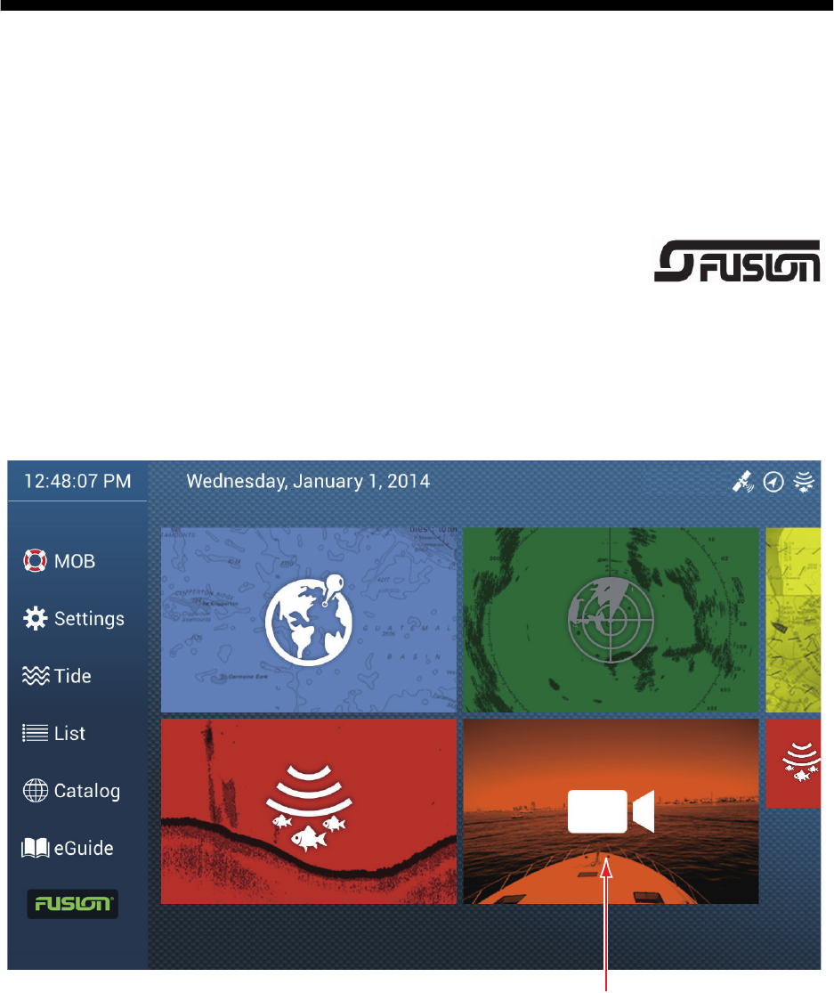
9.1 How to Display a Video Image
The camera application is included on the home screen. Tap the Home icon to show
the home screen. Tap the camera display icon to activate the camera display.
Camera display
9. CAMERA/VIDEO/FUSION-Link
9-2
9.2 Video Signal Type
There are three types of video signals connected to this equipment.
• Analog: Images from a video player, on-board camera or DVD player
• FLIR: Images from a FLIR brand infrared camera
• OceanView: Images from an Oceanview brand camera
9.3 How to Set the Video Display
9.3.1 How to set the video signal
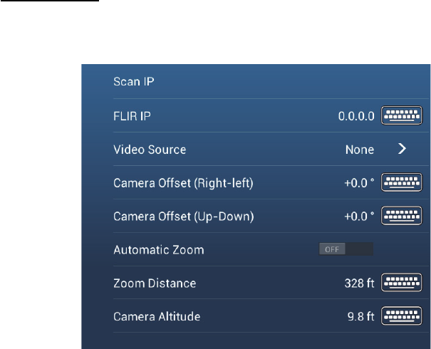
FLIR camera
Images from an infrared camera allow you to navigate easily at night or in bad weath-
er. Open the home screen, then [Settings] - [Camera] - [FLIR Installation].
Note: To use the PTZ function of the FLIR camera with the NavNet TZtouch2, a set-
ting (Nexus CGI Interface, port: 8090) is required at the FLIR camera. See the opera-
tor’s manual of the FLIR camera for details.
[Scan IP]: Tap [Scan IP] to scan the IP address automatically when connecting an
FLIR camera.
[FLIR IP]: Enter the IP address manually with the software keyboard then tap .
[Video Source]: Select the input source for the FLIR.
[Camera Offset (Right-left)]: Adjust the side position of the FLIR camera.
[Camera Offset (Up-Down)]: Adjust the up-and down position of the FLIR camera.
[Automatic Zoom]: Turn on to turn on the automatic zoom.
[Zoom Distance]: Set the distance to zoom automatically.
[Camera Altitude]: Set the altitude for the FLIR camera.
9. CAMERA/VIDEO/FUSION-Link
9-3
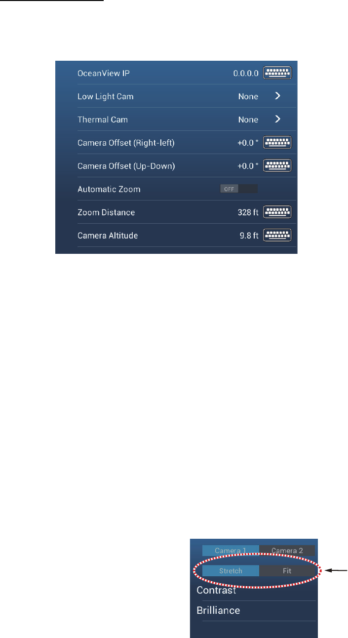
OceanView camera
Images from an OceanView camera allow you to navigate easily at night or in bad
weather. Open the home screen, then tap [Settings] - [Camera] - [OceanView Instal-
lation].
[OceanView IP]: Enter the IP address of the OceanView camera.
[Low Light Cam]: Select the low light camera (if any).
[Thermal Camera]: Select the thermal camera (if any).
[Camera Offset (Right-left)]: Adjust the side position of the FLIR camera.
[Camera Offset (Up-Down)]: Adjust the up-and down position of the FLIR camera.
[Automatic Zoom]: Turn on to turn on the automatic zoom.
[Zoom Distance]: Set the distance to zoom automatically.
[Camera Altitude]: Set the altitude for the FLIR camera.
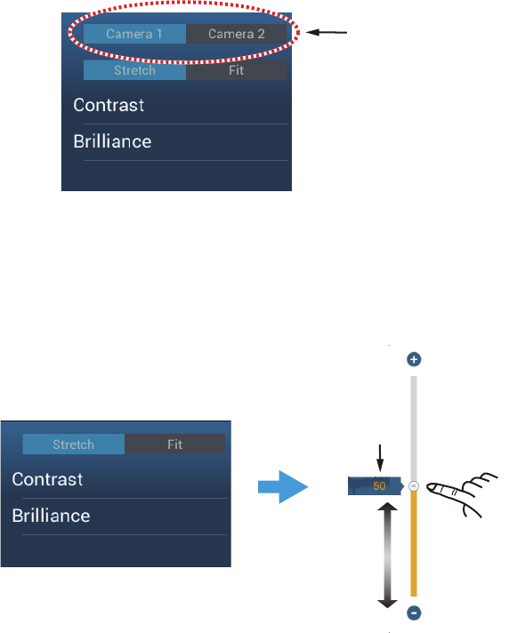
9.3.2 How to adjust the image size
You can adjust the image size from the pop-up menu.
1. In the camera mode, tap the screen to show the pop-up menu.
2. Tap the camera display to adjust.
3. Tap [Stretch] or [Fit].
[Stretch]: Shrink or enlarge the
image to fit the monitor’s width.
[Fit]: Shrink or enlarge the image
to fit the monitor’s height. The as-
pect ratio is kept, so a black bar
appears on the right and left sides
of the picture, but this is normal.
4. Adjust the top slider for width; bottom slider for height.
5. Tap the close button to finish.
Stretch, fit
9. CAMERA/VIDEO/FUSION-Link
9-4
9.3.3 How to switch your video inputs
If you have more than one camera installed, you can switch your video inputs from the
camera screen.
1. On a camera display, tap the screen to show the pop-up menu.
2. Tap the camera image to show, at the top of the window.
9.3.4 How to adjust the video image
Tap the screen to show the pop-up menu. Tap [Contrast] or [Brilliance], then drag the
slider to adjust.
Input sources
Drag slider
to set.
Current
setting
Tap screen to show pop-up menu.
Tap [Contrast] or [Brilliance].
9. CAMERA/VIDEO/FUSION-Link
9-5
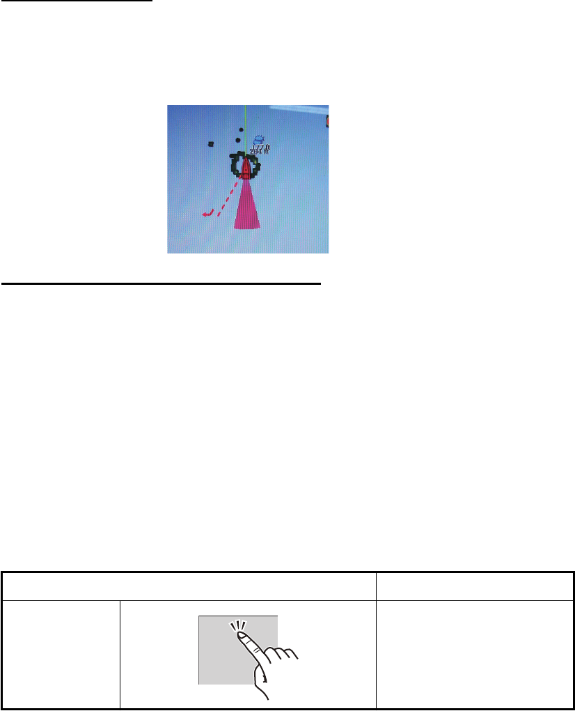
9.4 Control of FLIR Camera
[Camera FoV] menu
You can display the field of view by the FLIR camera on the plotter display.
1. Tap the boat icon to display the pop-up menu.
2. Tap [Cone]. The boat icon is put inside a red translucent circle.
[Move Camera] and [Lock Camera] menus
You can rotate the FLIR camera about the position you select (touch) on the plotter or
radar display. Open the pop-up menu then tap [Lock Camera]. To track the position,
tap [Move Camera] on the pop-up menu.
9.5 Tracking Active Waypoint, MOB
The camera can be set to automatically track the active waypoint and/or MOB. Open
the [Settings] - [Camera] menu and then turn on [Automatic Lock on Active Waypoint]
or [Automatic Lock on MOB] as required.
9.6 Touch Control on the Camera Display
Operation Function
Tap Opens the pop-up menu.
During zoom mode, center
the position tapped.
9. CAMERA/VIDEO/FUSION-Link
9-6
9.7 FUSION-Link
FUSION-Link allows compatible NavNet TZtouch2 displays to interface and achieve
control of specialized FUSION marine entertainment equipment.
9.7.1 How to access the FUSION screen and controls
The FUSION controls can be accessed in three methods:
• FUSION on the home screen
• Slide-out menu (minimized screen appears), and
• Function Gesture
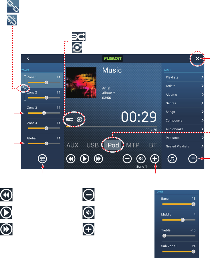
Method 1: FUSION icon (for full window)
Tap [FUSION] om the home screen.
Example1: iPod in the full screen
Drag
slider to
adjust
volume.
Show or hide [ZONES] panel.
Show or hide
[MENU] panel.
Tap: Goto previous title.
Hold down: Go back.
Close
button
Tap: Goto next number.
Hold down: Fast forward.
Swipe to
change
source.
Show or hide [TONES] panel
(tone controls).
Playback
Lower volume.
Raise volume.
Mute/unmute.
Select track/album.
Repeat on/off.
Globally
adjust
volume.
Zones 1 and 2 volumes synched.
Zones 1 and 2 volumes independent.