Furuno USA 9ZWRTR104 Transceiver for Radar Sensor DRS4DL User Manual
Furuno USA Inc Transceiver for Radar Sensor DRS4DL
Contents
- 1. User Manual I
- 2. User Manual II Part 1
- 3. User Manual II Part 2
- 4. User Manual II Part 3
- 5. User Manual II Part 4
- 6. User Manual II Part 5
- 7. User Manual II Part 6
- 8. User Manual II Part 7
- 9. User Manual II Part 8
- 10. User Manual II Part 9
- 11. User Manual II Part 10
- 12. User Manual II Part 11
- 13. User Manual II Part 12
User Manual II Part 12
13. OTHER FUNCTIONS
13-9
13.5 Software Update
You can update the software for this equipment via the internet. See section 1.18 for
how to connect to the internet. It is recommended to back up stored data (waypoints,
routes, etc.) to a micro SD card before updating the software, in case something
should go wrong during the updating.
1. Open the home screen, then tap [Settings] - [General].
2. Tap [Check for Software Update]. The following messages appear.
3. Tap [Yes].
The system starts updating. Do not turn off the power during the updating. The power
switch turns orange when the updating is completed.
iSoftware Update
Checking new version availability...
NEW VERSION DETECTED:
BILLFISH VERSION 1.0.0
(SIZE = 1.45 MB)
DO YOU WANT TO DOWNLOAD IT?
Yes
No
13. OTHER FUNCTIONS
13-10
13.6 How to Manage Your Charts
The NavNet TZtouch2 uses the same Mapmedia charts as NavNet 3D. Even though
NavNet TZtouch2 is a master-less system in networking, for charts one NavNet
TZtouch2 unit should be set as Chart Master to share the System ID, which will be
necessary to obtain an unlock code of a chart from Mapmedia.
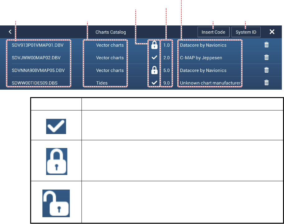
13.6.1 How to view your charts
Tap the Home icon to show the home screen, then tap [Catalog] to display your charts
catalog.
Icon Meaning
Free chart. An unlock code is not necessary.
Unlock code is necessary to use the chart. Tap the [Insert Code] but-
ton at the top of the [Charts Catalog]. Enter the unlock code then tap
to finish.
Unlock code entered for the chart.
System ID
display
Tap to enter
unlock code
Chart manufacturer
Chart file name Chart file type
Chart status
(see below)
Chart
version
no.

13. OTHER FUNCTIONS
13-11
13.6.2 How to update or add charts
Free (USA and NOAA) and for-fee NavNet TZtouch2 compatible charts are provided
by FURUNO and Mapmedia. Go to the URLs shown below to download chart data.
Download the chart file to your desktop. Unzip the file, then copy it to the root of a mi-
cro SD card. Insert the card into the SD card slot on the display unit, or the left card
slot in the SD Card Unit (SD-001). For the detailed procedure, refer to the instructions
on the FURUNO website.
A for-fee chart requires that you enter its chart unlock code. Go to the Home screen
and tap [Catalog] to show the [Charts Catalog] display. Tap the [Insert Code] button
then enter the chart unlock code from the software keyboard.
Where to obtain chart data:
FURUNO
http://www.furunousa.com/Products/Products.aspx?category=Prod-
ucts+%3a+NavNet+TZtouch+%3a+Charts+for+NavNet+TZtouch
Mapmedia
http://www.mapmedia.com/charts-catalog.html
13.6.3 How to delete charts
Before replacing a chart you should delete the old chart data on every NavNet
TZtouch2 unit. Only delete the chart data that you intend to replace or no longer re-
quire.
Open the charts catalog. Tap the trashcan icon of the chart to delete. You are asked
"ARE YOU SURE YOU WANT TO DELETE THIS FILE?" Tap [OK] to delete the file.
13. OTHER FUNCTIONS
13-12
This page is intentionally left blank.
14-1
14. MAINTENANCE, TROUBLE-
SHOOTING
This chapter has information about maintenance and troubleshooting that the user
can follow to care for the equipment.
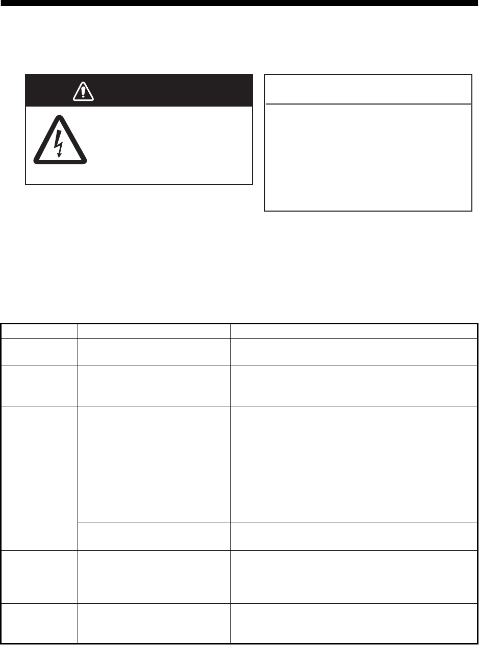
14.1 Maintenance
Routine maintenance helps keep your equipment in good condition and prevents fu-
ture problems. Check the items shown in the table below on a regular basis to help
keep your equipment in good condition for years to come.
Check item Check point Remedy
Cables Cable connection, corrosion Connect the cables that have loosened. Replace
any damaged cables.
Cabinet Dust on the cabinet Remove dust with a dry clean cloth. Do not use
commercial cleaners to clean the equipment - they
can remove paint and markings.
LCD Dust on the LCD Wipe the LCD carefully to prevent scratching, us-
ing tissue paper and an LCD cleaner. To remove
dirt or salt deposits, use an LCD cleaner, wiping
slowly with tissue paper so as to dissolve the dirt or
salt. Change paper frequently so the salt or dirt will
not scratch the LCD. Do not use solvents such as
thinner, acetone or benzene for cleaning. Also, do
not use degreaser or antifog solution, as they can
strip the coating from the LCD.
Waterdrops on the LCD Waterdrops on the LCD can slow touch response.
Wipe the LCD with a dry cloth to remove the water.
Radar
antenna
Foreign material on the radar
antenna
Foreign material can reduce sensitivity. Clean the
antenna with a cloth wetted with freshwater. Do not
use commercial cleaners to clean the radiator -
they can remove paint and markings.
Transducer Transducer face Marine growth on the transducer face can reduce
sensitivity. Remove any growth with a wooden
stick or fine grade sandpaper.
WARNING
ELECTRICAL SHOCK HAZARD
Do not open the equipment.
Only qualified persons can
work inside the equipment.
NOTICE
Do not apply paint, anti-corrosive
sealant or contact spray to plastic
parts or equipment coating.
Those items contain products that can
damage plastic parts and equipment
coating.
14. MAINTENANCE, TROUBLESHOOTING
14-2
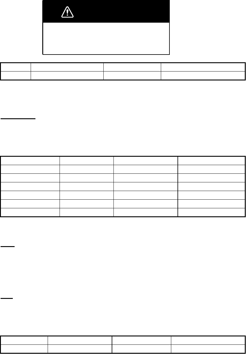
14.2 Fuse Replacement
The fuse in the fuse holder in the power cable protects the equipment from high elec-
tric current and equipment fault. If you cannot turn on the power, check the fuse to see
if it has blown. Find the reason for the blown fuse before you replace the fuse. If the
fuse blows again after the replacement, contact your dealer for information.
14.3 Life of the Parts
Magnetron
When a magnetron reaches the end of its life, targets do not appear on the radar dis-
play. If long-range performance appears to have decreased, contact your dealer about
replacement of the magnetron.
The total time of power-on ("ON TIME") and transmission ("TX TIME") are displayed
on the radar screen during the stand-by mode.
LCD
The life of the LCD is approximately 18,000 hours for the TZTL15F, and 25,000 hours
for the TZTL12F. The actual number of hours depends on ambient temperature and
humidity. When the brilliance cannot be raised sufficiently, contact your dealer about
replacement of the LCD.
Fan
The life of the fan is shown in the table below, and the actual life depends on ambient
temperature. When the fan does not rotate sufficiently, an applicable message ap-
pears. Turn off the power and contact your dealer about replacement of the fan.
WARNING
Use the proper fuse.
A wrong fuse can damage the equipment and
cause fire.
Name Type Code No. Remarks
Fuse FGBO-A 125V 5A PBF 000-155-853-10 12 VDC, 24 VDC
Radar Sensor Magnetron Code No. Approx. Life
DRS2D E3590 000-164-574-11 2,000 hours
DRS4D, DRS4DL E3571 000-146-867-11 2,000 hours
DRS4A MAF1421B 000-158-786-11 3,000 hours
DRS6A MAF1422B 000-158-788-12 3,000 hours
DRS12A MAF1565N 000-174-559-10 3,000 hours
DRS25A MG5436(E2V) 000-140-762-10 2,000 to 3,000 hours
Item Type Code No. Estimated Life
FAN MOTOR MFB52A-12HA-002 000-175-998-10 Approx. 21,000 hours

14. MAINTENANCE, TROUBLESHOOTING
14-3
14.4 Troubleshooting
This section provides simple troubleshooting procedures that the user can follow to re-
store normal operation. If you cannot restore normal operation, do not check inside the
unit. Have a qualified technician check the equipment.
14.4.1 General troubleshooting
14.4.2 Radar troubleshooting
14.4.3 Plotter troubleshooting
Problem Remedy
You can not turn on the power. • Check for blown fuse.
• Check that the power connector is fastened.
• Check for corrosion on the power cable connector.
• Check for damaged power cable.
• Check battery for correct voltage output.
Picture is not displayed properly. Turn off and on the power. If the picture is still improper, contact
your dealer for instructions.
Nothing appears on the screen
after you press the power switch.
Check if the unit is plugged in.
The display has frozen. Push the power switch until the screen goes blank. Turn the
power on again.
Problem Remedy
You tapped the [TX] icon on the
radar display to transmit but
nothing happens.
• Tap the [TX] icon again. (The icon is filled in white when the ra-
dar is in transmit state.)
• Check that the antenna cable is fastened.
• Check if the radar source is correct.
Marks and characters appear,
but echoes do not appear.
Check that the antenna cable is fastened.
Picture is not updated or the
picture freezes.
• Check antenna cable.
• If the picture has frozen, turn the power off and on again.
You tuned the receiver, but the
sensitivity is weak.
The magnetron may have reached its life. Have a technician
check the magnetron.
You changed the range, but the
radar picture does not change.
• Try to change the range again.
• Turn the power off and on again.
Poor discrimination in range. Adjust the sea control.
Range rings are not displayed. Check if [Range Rings] is turned on in the [Layers] menu.
You tapped the [TX] icon to
transmit. The "TX screen" ap-
pears momentarily, but the ra-
dar soon goes into stand-by.
This problem indicates that the overload protection has activated.
To restore normal operation, turn off all equipment in the network.
Wait a few seconds then turn on all the equipment.
Problem Remedy
Position is not fixed. Check for interfering objects near the display unit that might be
blocking reception.
The track of your ship is not
plotted.
The track display may be disabled. Check if [Tracks] is turned on
in the [Layers] menu.

14. MAINTENANCE, TROUBLESHOOTING
14-4
14.4.4 Fish finder troubleshooting
Problem Remedy
You selected a fish finder dis-
play, but no picture appears.
• Check that the transducer cable is fastened.
• Check that the fish finder source is correct.
• If you are using a network fish finder, check that it is properly
connected.
Marks and characters appear,
but no picture appears.
Check if the transducer cable is connected.
Picture appears but zero line
does not appear.
• The picture is shifted. Check the shift setting.
• Check if draft is set to zero or higher.
The picture sensitivity is too
low.
• If you are in the manual mode, check the gain setting.
• Check the transducer face for marine life or air bubbles.
• Bottom is too soft to return an acceptable echo.
The depth indication does not
appear.
• For manual operation, adjust gain and range to display the bot-
tom echo (in reddish-brown).
• Adjust bottom level HF/LF.
Noise or interference shows on
the display.
• Make sure the transducer cable is not near the engine.
• Check the ground.
• Check if another fish finder in the vicinity of your boat has the
same frequency as your fish finder.
• Try to reject the interference with [Interference Rejection] in the
[Settings] - [Sounder] menu.
AP-1
APPENDIX 1 MENU TREE
1
Settings
General
COG Vector (Distance, Time)
COG Vector Length (0 - 999.00(NM), 1.00)
COG Vector Time (0’10s, 0’30s, 1’00mn, 2’00mn, 5’00mn, 10’00mn,
15’00mn, 30’00mn 1h00’, 2h00’, 3h00’, 6h00’, 12h00’, 1d00h)
COG Vector Color (Red, Blue, Green, Yellow, Purple, Orange, Light-blue,
Black)
Heading Line Thickness (1 - 5 or 2 - 6, 1) (1 - 5=2D mode, 1 - 6=3D mode)
Vessel Icon Orientation (Heading, COG)
Track Interval (0’05s, 0’10s, 0’30s, 1’00mn, 5’00mn, 10’00mn)
Track Color (Fixed, Variable)
Fixed Color Setup (Red, Blue, Green, Yellow, Magenta, Orange, Cyan,
Black & White)
Variable Color (Depth, SST Range, SST Variation, Speed,
Bottom Discrimination)
Variable Color Setup (Open the dialog box for variable color setting.)
Track Thickness (1 - 10 or 2 - 11, 2) (1 - 10=2D mode, 2 - 11=3D mode)
Automatic Track Deleting (ON, OFF)
Delete All Tracks
Reset Default Settings
Default Route Color (Red, Blue, Green, Yellow, Magenta, Orange,
Cyan, Black & White)
Route Thickness (1 - 10 or 2 - 11, 2) (1 - 10=2D mode, 2 - 11=3D mode)
Navigate with Autopilot (ON, OFF) (Requires NAVpilot.)
Autopilot Step (2 - 30(°), 10)
Ask to Enter Route Name (ON, OFF)
Route Auto Zoom (ON, OFF)
WPT Switch Mode (Circle and Cross Line, Circle, Cross Line)
Switching Circle Radius (0 - 3278(ft), 200)
Waypoint Crossing Notification (ON, OFF)
End of Route Notification (ON, OFF)
Intelligent Route Waypoint Centering (ON, OFF)
Display XTE Lines (ON, OFF)
XTE Value (1 - 3278(ft), 200)
Cruising Speed for Planning (0 - 99(kt), 5)
Delete All Points & Routes
Reset Default Settings
Function Gesture (None, Facebook, Screen Capture, Event, Menu, Lists,
Tide, Fusion*, Fusion Bar*) * FUSION-Link equipment connected.
Connect to the Internet (Never, At Startup, When Necessary)
Wireless LAN Settings (Open the dialog box for Wireless LAN settings.)
Show Range Sliders (ON, OFF)
User Interface Auto-Hide (2 s, 3 s, 5 s, 10 s, 15 s)
Instrument Theme (Black, White)
Local Time Offset (UTC - 12:00 to UTC + 13:00)
Synchronize Time with GPS (ON, OFF)
Cross Cursor Speed (1 - 20, 8)
Demo File (Select file for use in demo mode.)
Manual Demo (ON, OFF)
Demo Speed (0 - 20(kn), 5)
Language (English, Others)
Check for Software Update
Data Usage (Shows number of points, routes and track points used.)
Reset Default Settings
Bold italic: Default setting
Ship &
Track
Routes

APPENDIX 1 MENU TREE
AP-2
1
Display Points Names (ON, OFF)
Default Point Symbol (Select the default icon for point.)
Default Point Color
(Red, Blue, Green, Yellow, Magenta, Orange, Cyan, Black & White)
Point Size (50 - 200(%), 100)
Icons Set (Classic, Modern)
Data to Be Recorded in Event Comment (None, Date, SST, Date And SST)
Record Event1 Automatically (ON, OFF)
Default Event 1 - 6 Symbol
Default Event 1 - 6 Color
Red Blue Green Yellow Purple Orange Light-blue Black
Delete All Points & Routes
Reset Default Settings
1
Points
Symbol1
default
Event1 default symbol
Event1 default symbol
Event3
default
symbol
Event3
default
symbol
Event2 default symbol
Event2 default symbol
Event4
default
symbol
Event4
default
symbol
Event5
default
symbol
Event5
default
symbol
Event6
default
symbol
Event6
default
symbol
Event1 Event2 Event3 Event4 Event5 Event6
default default default default default default
color color color color color color

APPENDIX 1 MENU TREE
AP-3
Grid Interval (Off, Very Small, Small, Medium, Large, VeryLarge)
Tide/Current Icons Size (50 - 150(%), 100)
NavData Transparency (0 - 80(%), 10)
PhotoFusion Transparency (0 - 80(%), 15)
Tide Range for PhotoFusion (0.0 - 60(ft), 0)
Tidal Currents Transparency (0 - 80(%), 25)
Radar Transparency (0 - 80(%), 20)
Range Link (ON, OFF)
Echo Color (Multicolor, Green, Yellow)
Depth Shading Transparency (0 - 80(%), 50)
Auto Depth Shading Color Scale (ON, OFF)
Minimum Value* (0000 - 33000(ft), 0)
Maximum Value* (00000 - 33000(ft), 200)
Depth Color Shade (Classic Hue, Inverted Classic Hue, Red Hue, Blue Hue,
Green Hue, Yellow Hue)
Auto Alti 3D Exaggeration (ON, OFF)
3D Alti Exaggeration (1 - 20, 3)
Reset Default Settings
Chart Object Size (50 - 200(%), 100%)
Chart Color Palette (S-52, Standard, Sunlight)
Chart Symbols (S-52, International)
Shallow Contour (0.0, 3.0, 6.0, 9.0, 12.0, 15.0, 18.0, 21.0, 24.0, 27.0, 30.0 (ft)
Safety Contour (0.0, 3.0, 6.0, 9.0, 12.0, 15.0, 18.0, 21.0, 24.0, 27.0, 30.0, 50.0,
70.0, 100, 200 (ft))
Deep Contour (0.0, 3.0, 6.0, 9.0, 12.0, 15.0, 18.0, 21.0, 24.0, 27.0, 30.0, 50.0,
70.0, 100, 200, 300, 500, 1,000, 2,000 (ft))
Text (Important) (ON, OFF)
Text (Other) (ON, OFF)
Display Buoy Names (ON, OFF)
Display Light Description (ON, OFF)
Display Light Sectors (ON, OFF)
Display Routes (ON, OFF)
Display Routes Bearings (ON, OFF)
Display Soundings (ON, OFF)
Display Soundings in Red (ON, OFF)
Obs. Depth Below Safety (ON, OFF)
Display Seabed (ON, OFF)
Cautionary Areas (ON, OFF)
Reset Default Settings
Shallower than... (0.0, 3.0, 6.0, 9.0, 12.0, 15.0,
18.0, 21.0, 24.0, 27.0, 30.0, 50.0, 70.0, 100(ft))
Plotter
1
1
* Auto Depth Shading
Color Scale OFF
Vector
Chart

APPENDIX 1 MENU TREE
AP-4
S-52 Vector Chart Display Mode (Custom, Base, Standard, Other, Fishing)
Unknown Object (ON, OFF)
Chart Data Coverage (ON, OFF)
Water and Seabed Features (ON, OFF)
Traffic Routes (ON, OFF)
Information Areas (ON, OFF)
Buoys & Beacons (ON, OFF)
Lights (ON, OFF)
Fog Signals (ON, OFF)
Radar (ON, OFF)
Information About Chart Data (ON, OFF)
Obstructions (ON, OFF)
Depth Contours, Cur., etc (ON, OFF)
Fishing Facilities (ON, OFF)
Services (Pilot, Signal Stations) (ON, OFF)
Harbour Facilities (ON, OFF)
Services and Small Craft Facilities (ON, OFF)
Land Features (ON, OFF)
Reset Default Settings
1
1
S-52
Display
Weather Load Weather File (Open the dialog box to select the weather file to load.)
Weather Data Server (NavCenter, Sirius)
Sirius Weather Radar (USNowRadar, CanadianRadar)
Zone Forecast (BBWX2 only)
Marine Warnings (BBWX2 only)
Tropical Infos (BBWX2 only)
Sirius Diagnostic (BBWX2 only)
Tidal Step (5 mn, 10 mn, 15 mn, 20 mn, 30 mn, 1 h, 2 h, 3 h, 6 h, 12 h)
Duration of Animation (5 s, 10 s, 15 s, 20 s, 30 s, 45 s, 1 mn, 2 mn, 3 mn)
Model (USA, Worldwide)
Forecast Days (1 - 16, 4)
Wind (ON, OFF)
Waves (ON, OFF)
Cloud (ON, OFF)
Rain/Snow (ON, OFF)
Air Temperature (ON, OFF)
Pressure (ON, OFF)
500mb (ON, OFF)
Sea Surface Temperature (ON, OFF)
Oceanic Currents (ON, OFF)
Altimetry (ON, OFF)
Plankton (ON, OFF)
Weather Color Transparency (0 - 80; 40%)
AUTO SST Color Scale (ON, OFF)
Reset Default Settings
Minimum Value (15 - 120(°F), 50°)
Maximum Value (15 - 120(°F), 90°)

APPENDIX 1 MENU TREE
AP-5
Radar Source (Select the antenna host name.)
Day Background Color (Black, Dark Blue, White)
Night Background Color (Black, Dark Blue)
Echo Color (Multicolor, Green, Yellow)
Rings Interval (Auto, 1, 2, 3, 4, 5, 6, 7, 8, 9)
Own Ship Icon (ON, OFF)
Echo Interpolation (ON, OFF)
Bearing Scale Mode (Relative, True)
EBL Reference (True, Relative)
Watchman (5 minutes, 10 minutes, 20 minutes)
Antenna Rotation (Auto, 24 RPM)
Antenna Heading Align (-180 - +180(°), 0)
Main Bang Suppression (0 - 100, 0)
Enable Sector (1, 2) Blanking (ON, OFF)
Start Angle* (0 - 360, 0)
End Angle* (0 - 360, 0)
Antenna Longitudinal Position (0 - 3275(ft), 20)
Antenna Lateral Position (-Port) (-320 - 320(ft), 0)
Antenna Height (For DRS: Under 3 m, 3 m - 10 m, Over 10 m)
(For IMO: 5 m, 7.5 m, 10 m, 15 m, 20 m, 25 m, 30 m, 35 m, 40 m, 45 m, 50 m)
Auto Tuning (ON, OFF)
Tuning Source (Range1, Range2)
Manual Tuning** (-50 - 50, 0)
Radar Monitoring (Open the radar monitor window.)
Radar Optimization
ARPA Advanced Settings (Open the dialog box for ARPA setting.)
Hardware Factory Default
Reset Default Settings
1
1
Radar
* Available when [Enable Sector (1, 2)
Blanking] is [ON].
Display Target IDs (ON, OFF)
Hide AIS Targets Farther than ... (1 NM, 2 NM, 3 NM, 6 NM, 12 NM, 18 NM,
24 NM, 48 NM, 84 NM, 96 NM)
Ignore Alarms for AIS Slower than... (0.0 - 9.9(kn), 1)
CPA/TCPA Alarm (ON, OFF)
CPA Alarm Value (0.01 - 99. 99(NM), 0.5)
TCPA Alarm Value (0 - 59(min), 10)
Proximity AIS Target Alarm (ON, OFF)
Proximity AIS Target Alarm Value (10 - 999(m), 100)
Buddies List (AIS & DSC) (Open the buddies list.)
Reset Default Settings
**Available when [Auto Tuning] is [OFF].
Targets

APPENDIX 1 MENU TREE
AP-6
Fish Finder Source (TZTL, network sounder name if connected)
Day Background Color (White, Light Blue, Black, Dark Blue)
Night Background Color (Black, Dark Blue)
Echo Color Levels (8 Colors, 16 Colors, 64 Colors)
A-Scope Peak Hold (ON, OFF)
Zoom Reference Lines (ON, OFF)
High Resolution (ON, OFF)
Picture Advance (4/1, 2/1, 1/1, 1/2, 1/4, 1/8, 1/16, Stop)
Range Shift (0 - 999(ft), 0)
Bottom Range Shift Area (15 - 85(%),75)
Zoom Range Span (6 - 350(ft), 30)
Bottom Lock Range Span (6 - 350(ft), 30)
ACCU-FISH Info (Depth, Fish Size)
ACCU-FISH Symbols (Off, Solid, Striped)
ACCU-FISH Size Correction (-80 - 100(%), 0)
Interference Rejection (Off, Low, Medium, High, Auto)
Heaving Correction (ON, OFF; external sounder only)
Clutter (0 - 100(%), 0)
TVG HF (0 - 9, 5)
TVG LF (0 - 9, 5)
Transmit Rate Auto (ON, OFF)
Transmit Rate Manual (0 - 21, 21)
Sounder Transmit (ON, OFF)
Fish Alarm (ON, OFF)
Fish Alarm for Bottom Lock (ON, OFF)
Fish Alarm Level (Low, Medium, High)
Zero Line Rejection (ON, OFF)
Zero Line Range (1.4 - 2.5, 2.0)
Transducer Draft (0.0 - 99.9(ft), 3.0)
Salt Water (ON, OFF)
Fish Finder Source (TZTL, network sounder name if connected)
Transducer Setup (Open the dialog box for transducer setting.)
Transmission Power (0 - 10, 10) (not available with DFF1-UHD
External KP (ON, OFF) (External sounder only.)
Bottom Level HF (-40 - +40)*
1
Bottom Level LF (-40 - +40)*
1
Gain Offset HF (-50 - +50)*
1
Gain Offset LF (-50 - +50)*
1
Auto Gain Offset HF (-5 - +5)*
1
Auto Gain Offset LF (-5 - +5)*
1
STC HF (0 - 10)*
2
STC LF (0 - 10)*
2
Frequency Adjust HF (-50 - 50)*
3
Frequency Adjust LF (-50 - 50)*
3
TX Pulse HF (Short 1, Short 2, Standard, Long)*
3
TX Pulse LF (Short 1, Short 2, Standard, Long)*
3
RX Band HF (Narrow Standard, Wide)*
3
RX Band LF (Narrow, Standard, Wide)*
3
Temperature Port (MJ Port, Low Frequency, High Frequency)*
4
Set Hardware to Factory Default (External sounder only)
Reset Default Settings
1
1
Sounder
Range Minimum Value (0 - 3600(ft), 0.0)*
Range Maximum Value (0 - 3600(ft), 10.0)*
Range Minimum Value(0 - 360(ft), 0.0)*
Range Maximum Value (0 - 360(ft), 1.0)*
* Value for internal
sounder. Different
with external
sounder.
*
1
Internal, DFF1, DFF3, BBDS1, DFF1-UHD
*
2
DFF3, DFF1-UHD
*
3
DFF3
*
4
DFF3, DFF1-UHD

APPENDIX 1 MENU TREE
AP-7
Alarm
1
Export File Format (TZD, CSV, GPX, KML)
Import Points & Routes (Open the dialog box for import.)
Export All Points & Routes (Open the dialog box for export.)
Import Tracks (Open the dialog box for import.)
Export Tracks (Open the dialog box for export.)
BackUp Settings (Open the dialog box for backup.)
Restore Settings (Open the dialog box for restoring.)
Bearing Display (Magnetic, True)
True Wind Calculation Reference (Ground, Surface)
Position Format (DDD°MM.mmmm’, DDD°MM.mmm’, DDD°MM.mm’,
DDD°MM’SS.ss”, DDD.dddddd°, Loran-C, MGRS)
Short/Long Change Over (0.0 - 2.0; 0.5 NM)
Range (Long) (Nautical Mile, Kilometer, Mile)
Range (Short) (Foot, Meter, Yard)
Depth (Foot, Meter, Fathom, Passi Braza)
Height/Length (Foot, Meter)
Fish Size (Inch, Centimeter)
Temperature (Fahrenheit Degree, Celsius Degree)
Boat Speed (Knot, Kilometer per Hour, Mile per Hour, Meter per Second)
Wind Speed (Knot, Kilometer per Hour, Mile per Hour, Meter per Second)
Atmospheric Pressure (HectoPascal, Millibar, Millimeter of Mercury, Inch of
Mercury)
Oil Pressure (KiloPascal, Bar, Pound per Square Inch)
Volume (Gallon, Liter)
Reset Default Settings
Hardware Alarm (ON, OFF)
XTE Alarm (ON, OFF)
Depth Alarm (ON, OFF)
Depth Alarm Value (0 - 900(ft), 30)
Sea Surface Temperature Alarm (Off, Over, Under, Within, Out of)
Temperature Alarm Value (32 - 140(°F), 70.00)
Temp. Alarm Range Minimum Value (15 - 160(°F), 60.0)
Temp. Alarm Range Maximum Value(15 - 160(°F),70.0)
Temp. Shear Alarm Value (30 - 50(°F), 33.0)
Speed Alarm (Off, Over, Under)
Speed Alarm Value (0 - 99.9(kn), 10.0)
Anchor Watch Alarm (ON, OFF)
Anchor Watch Alarm Value (1 - 3300(ft), 150)
Notification Sound (ON, OFF)
Alarm Sound (ON, OFF)
Sound Alarm Until Acknowledged (ON, OFF)
Save Log File as (Save log file to micro SD card.)
Reset Default Settings
1
Files
Units

APPENDIX 1 MENU TREE
AP-8
GPS POSITION
Longitudinal (from bow)
Lateral (-Port)
Boat Length
Size of Static Icon
Depth Display
Transducer Draft
Keel Draft
Graphic Instruments Setup
Minimum Boat Speed
Maximum Boat Speed
DEPTH
Minimum Depth
Maximum Depth
SEA SURFACE TEMPERATURE
Minimum Sea Surface Temperature
Maximum Sea Surface Temperature
PROPULSION ENGINE
Max. RPM
Red Zone Oil Pressure
Max. Oil Pressure
Min. Temperature
Red Zone Temperature
OTHER ENGINE (same options as PROPULSION ENGINE)
Reset Instrument Pages
Reset Default Settings
VIDEO INPUT 1
VIDEO INPUT 2
CONTROLLABLE CAMERA
FLIR Installation
OceanView
Installation
Camera
Connected (ON, OFF)
NickName (Camera 1)
Scan IP
FLIR IP
Video Source (None, Camera 1, Camera 2)
Camera Offset (Right-left) (0°)
Camera Offset (Up-Down) (0°)
Automatic Zoom (ON, OFF)
Zoom Distance (300 ft)
Camera Altitude (30 ft)
Connected (ON, OFF)
NickName (Camera 2)
OceanView IP
Low Light Cam (None, Camera 1, Camera 2)
Thermal Cam (None, Camera 1, Camera 2)
Camera Offset (Right-left) (0°)
Camera Offset (Up-Down) (0°)
Automatic Zoom (ON, OFF)
Zoom Distance (300 ft)
Camera Altitude (30 ft)
Automatic Lock on Active Waypoint (ON, OFF)
Automatic Lock on MOB (ON, OFF)
Reset Default Settings
Initial
Setup
(see
Inst.
Manual
for
details)
1

APPENDIX 1 MENU TREE
AP-9
DATA ACQUISITION
GP330B WAAS Mode
WS200 WAAS Mode
Data Source
Sensor List
NMEA 0183 Output
NMEA 2000 PGN Output
Sky View
INTERNAL GPS SETUP
WAAS Mode
SC-30 SETUP
WAAS Mode
Heading Offset
Pitch Offset
Roll Offset
CALIBRATION
Heading
Speed Through Water
Wind Speed
Wind Angle
Sea Surface Temperature
DATA DAMPING
COG & SOG
Heading
Speed Through Water
Wind Speed & Angle
Rate of Turn
BROWSER INSTALLATION
FAX30 Browser
FA30 Browser
FA50 Browser
Chart Master Device
System ID
IP Address
Quick Self Test
Serviceman
Event/Buzzer Port Configuration
Event Input Configuration
Reset Default Settings
1

AP-10
APPENDIX 2 RADIO REGULATORY
INFORMATION
Wireless Interoperability
This product is designed to be interoperable with any wireless LAN product that is based on direct
sequence spread spectrum (DSSS) and orthogonal frequency division multiplexing (OFDM) radio
technology and to comply with the following standards.
• IEEE Std 802.11b Standard on 2.4 GHz Wireless LAN
• IEEE Std 802.11g Standard on 2.4 GHz Wireless LAN
• IEEE Std 802.11n Standard on 2.4 GHz Wireless LAN
Safety
This product, like other radio devices, emits radio frequency electromagnetic energy. The level of
energy emitted by this device, however, is less than the electromagnetic energy emitted by other
wireless devices such as mobile phones. This product operates within the guidelines found in ra-
dio frequency safety standards and recommendations. These standards and recommendations
reflect the consensus of the scientific community and result from deliberations of panels and com-
mittees of scientists who continually review and interpret the extensive research literature. In
some situations or environments, the use of this product may be restricted by the proprietor of the
building or responsible representatives of the applicable organization. Examples of such situa-
tions include the following:
• Using this product onboard airplanes, or
• Using this product in any other environment where the risk of interference with other devices or
services is perceived or identified as being harmful.
If uncertain of the policy that applies to the use of wireless devices in a specific organization or
environment (an airplane, for example), ask for authorization to use this product before turning it
on.
Export Regulation
Radio wave certification is necessary at the export destination. The Wireless LAN of this product
operates in the 2.4 GHz band, which does not require a license in most countries. However, the
conditions for use of the wireless LAN depend on the country or the area.

APPENDIX 2 RADIO REGULATORY INFORMATION
AP-11
USA-Federal Communications Commission (FCC)
Below are descriptions for built-in Wireless LAN module.
This equipment has been tested and found to comply with the limits for a Class B digital device,
pursuant to Part 15 of FCC Rules. These limits are designed to provide reasonable protection
against harmful interference in a residential installation. This equipment generates, uses, and can
radiate radio frequency energy. If not installed and used in accordance with the instructions, it may
cause harmful interference to radio communications. However, there is no guarantee that interfer-
ence will not occur in a particular installation.
If this equipment does cause harmful interference to radio or television reception, which can be
determined by tuning the equipment off and on, the user is encouraged to try and correct the in-
terference by one or more of the following measures:
• Reorient or relocate the receiving antenna.
• Increase the distance between the equipment and the receiver.
• Connect the equipment to outlet on a circuit different from that to which the receiver is connect-
ed.
• Consult the dealer or an experienced radio/TV technician for help.
This device complies with part 15 of the FCC Rules. Operation is subject to the following two con-
ditions: (1) This device may not cause harmful interference, and (2) this device must accept any
interference received, including interference that may cause undesired operation.
Any changes or modifications not expressly approved by the party responsible for compliance
could void the user's authority to operate the equipment.
Caution: Exposure to Radio Frequency Radiation.
This equipment complies with FCC radiation exposure limits set forth for an uncontrolled environ-
ment and meets the FCC radio frequency (RF) Exposure Guidelines in Supplement C to OET65.
This equipment should be installed and operated keeping the radiator at least 20cm or more away
from person's body.
This device must not be co-located or operating in conjunction with any other antenna or transmit-
ter.

APPENDIX 2 RADIO REGULATORY INFORMATION
AP-12
Canada-Industry Canada (IC)
Below are descriptions for built-in Wireless LAN module.
This device complies with RSS 210 of Industry Canada.
Operation is subject to the following two conditions:
(1) This device may not cause interference, and
(2) This device must accept any interference, including interference that may cause undesired op-
eration of this device.
L'utilization de ce dispositif est autorisée seulement aux conditions suivantes:
(1) il ne doit pas produire de brouillage et
(2) l'utilisateur du dispositif doit étre prêt à accepter tout brouillage radioélectrique reçu, même si
ce brouillage est susceptible de compromettre le fomctionnement du dispositif.
Caution: Exposure to Radio Frequency Radiation.
This equipment complies with IC radiation exposure limits set forth for an uncontrolled environ-
ment and meets RSS-102 of the IC radio frequency (RF) Exposure rules. This equipment should
be installed and operated keeping the radiator at least 20cm or more away from person's body.
Cet équipement est conforme aux limites d'exposition aux rayonnements énoncées pour un envi-
ronnement non contr êolé et respecte les règles d'exposition aux fréquences radioélectriques
(RF) CNR-102 de l'IC. Cet équipement doit etre installé et utilise en gardant une distance de 20
cm ou plus entre le dispositif rayonnant et le corps.
To reduce potential radio interference to other users, the antenna type and its gain should be so
chosen that the equivalent isotropically radiated power (EIRP) is not more than that required for
successful communication.
FURUNO
TZTL12F/15F
SP - 1 E4487S01A-M
SPECIFICATIONS OF MULTI FUNCTION DISPLAY
TZTL12F/15F
1 GENERAL
1.1 Display
TZTL12F 12.1-inch wide TFT color LCD, 1280 x 800 (WXGA)
TZTL15F 15.6-inch wide TFT color LCD, 1366 x 768(XGA)
1.2 Indication system Raster-scan, non-interlace
1.3 Brightness 1000 cd/m2 typical (TZTL12F), 900 cd/m2 typical (TZTL15F)
1.4 Display colors 16,770,000 colors (plotter), 60 colors (echo), 16 colors (radar)
2 PLOTTER FUNCTION
2.1 Display mode Course plot, NAV data
2.2 Projection Mercator
2.3 Usable area 85° latitude or below
2.4 Memory capacity Track: 30,000 points, Route: 20,000 points
2.5 MOB 1 point
2.6 GPS receiver
3 RADAR INDICATION
3.1 Orientation mode Head-up, North-up (heading data required)
3.2 Echo trail 15/30s, 1/3/5/6/15/30 min. and continuous
3.3 Alarm Guard zone, Watchman, CPA/TCPA
4 SOUNDER INDICATION
4.1 Output 600 Wrms or 1 kWrms (MB-1100 required)
4.2 Frequency 50/200 kHz alternative output
4.3 Display mode AccufishTM, A-scope, Auto (Fishing/ Cruising/ Manual),
Temperature graph
4.4 Alarm Fish, Shear
5 OTHER FUNCTIONS
5.1 Instrument data display Weather sensor, Engine monitoring sensor or other instruments
required
5.2 Camera monitor IP camera or NTSC/PAL data required
5.2.1 Language Chinese, Danish, Dutch, Finnish, French, German, Greek, Italian
Japanese, Norwegian, Portuguese, Spanish, Swedish, Turkish,
UK/US
5.3 AIS information AIS receiver required
5.4 DSC display Target data required
5.5 Alarm Proximity AIS targets, Ignore AIS target, DSC receiving
FURUNO
TZTL12F/15F
SP - 2 E4487S01A-M
6 INTERFACE
6.1 Number of port
LAN 1 port, Ethernet 100Base-TX
NMEA2000 1 port (LEN=1)
USB 1 port, USB2.0
Video output 1 port, HDMI (TZTL12F:WXGA, TZTL15F: )
Video input 2 ports, NTSC/PAL
SD card slot 1, micro-SDXC
Contact closure 1, operator fitness signal (normal open)
6.2 Wireless LAN IEEE802.11b/g/n
Transmitting frequency 2.412 to 2.462 GHz
Output power 12 dBm max.
6.3 NMEA0183 (V2.0) sentences (Ethernet)
Input/output CUR, DPT, GGA, GSA, HDG, HDT, MDA, MTW, MWV, RSA, ROT,
VDM, VHW, VTG, XDR, ZDA
6.4 NMEA2000 PGN
Input 059392/904, 060928, 061184, 065280, 126208/720/992/996,
127237/245/250/251/257/488/489/505, 128259/267,
129025/026/029/033/038/039/040/041/538/540/793/794/798,
129025/026/029/033/038/039/040/041/538/540/793/794/798,
129808/809/810, 130306/310/311/312/313/314/577/578
Output 059392/904, 060928, 061184, 126208/464/720/992/996,
127250/251/257/258, 128259/267,
129025/026/029/033/283/284/285, 130306/310/312/313/314
7 POWER SUPPLY
6.1 Multi function display
TZTL12F 12-24 VDC: 2.6-1.3 A
TZTL15F 12-24 VDC: 3.2-1.6 A
6.2 Rectifier (option) 100-115/220-230 VAC, 1 phase, 50/60Hz
7 ENVIRONMENTAL CONDITIONS
7.1 Ambient temperature -15°C to +55°C
7.2 Relative humidity 95% or less at +40°C
7.3 Degree of protection IP56
7.4 Vibration IEC 60945 Ed.4
8 UNIT COLOR
N2.5 (fixed)

IN-1
INDEX
Numerics
2D/3D switch ............................................. 3-2
3D display
activating ................................................. 3-2
description............................................... 3-1
exaggeration ........................................... 3-3
A
ACCU-FISH
description............................................. 7-13
fish size correction ................................ 7-15
information ............................................ 7-15
setting.................................................... 7-14
showing/hiding symbol .......................... 7-15
Advanced Wx data .................................. 11-7
AIS
buddies list ............................................ 12-6
finding target on plotter display ............. 12-6
hiding AIS symbols out of
specified range ................................... 12-3
ignoring slow targets ............................. 12-3
list.......................................................... 12-5
locating target on plotter display ........... 12-6
lost target .............................................. 12-2
nickname of target................................. 12-6
proximity AIS target alarm..................... 12-3
showing/hiding symbols ........................ 12-1
target data with pop-up menu ............... 12-4
target details.......................................... 12-5
target IDs............................................... 12-4
target symbols....................................... 12-1
AIS list ..................................................... 12-5
AIS transponder (FA-30, FA-50) setup ... 12-7
Alarm sensitivity (fish finder) ................... 7-13
Alarms
alarm menu ........................................... 2-12
anchor watch......................................... 2-15
audio alarm silencing ............................ 2-12
audio alarm type.................................... 2-15
aural alarm on/off .................................. 2-15
bottom lock fish alarm ........................... 7-12
CPA/TCPA ............................................ 6-25
depth ..................................................... 2-13
fish......................................................... 7-12
hardware ............................................... 2-15
proximity AIS target............................... 12-3
speed .................................................... 2-14
SST ....................................................... 2-13
XTE ....................................................... 2-13
Alarms list................................................ 2-16
Anchor watch alarm ................................ 2-15
Animation radar....................................... 11-8
ARPA
automatic target acquisition .................. 6-23
clearing lost target................................. 6-24
CPA/TCPA alarm .................................. 6-25
manual target acquisition ...................... 6-23
showing/hiding display .......................... 6-22
stop tracking target................................ 6-24
target data ............................................. 6-24
A-scope display......................................... 7-5
B
Background color
fish finder............................................... 7-17
radar...................................................... 6-16
Boat icon
COG vector ............................................. 2-4
description............................................... 2-4
heading line............................................. 2-4
orientation................................................ 2-5
Bottom discrimination display.................... 7-6
Bottom level ............................................ 7-19
Bottom lock display ................................... 7-4
Bottom lock fish alarm
activating, deactivating.......................... 7-13
sensitivity............................................... 7-13
setting.................................................... 7-12
Bottom range shift area........................... 7-17
Bottom zoom display................................. 7-4
Buddies list.............................................. 12-6
C
Camera/Video
contrast adjustment................................. 9-4
FLIR camera............................................ 9-2
image size ............................................... 9-3
OceanView camera................................. 9-3
showing ................................................... 9-1
switching inputs....................................... 9-4
touch control............................................ 9-5
tracking active waypoint, MOB ................ 9-5
Charts
adding.................................................. 13-11
deleting................................................ 13-11
object information.................................... 2-7
panning.................................................... 2-3
range ....................................................... 2-2
S52 charts objects................................. 2-10
type.......................................................... 2-1
updating............................................... 13-11
vector charts text and object
information.............................................. 2-9
viewing ................................................ 13-10
zoom in, zoom out................................... 2-2
Clutter (fish finder)..................................... 7-9
COG vector ............................................... 2-4
Controls..................................................... 1-2
CPA/TCPA alarm .................................... 6-25
INDEX
IN-2
D
Data area
adding data to ........................................1-16
contents of data box...............................1-16
data format (analog or digital) ................1-18
deleting data box from............................1-17
description..............................................1-15
order of data...........................................1-15
transparency ..........................................1-18
Depth alarm .............................................2-13
Depth measurement ................................7-10
Depth shading overlay
description................................................3-4
settings.....................................................3-5
Display brilliance ........................................1-7
Display icons
description................................................1-9
editing........................................... 1-11, 1-12
removing ................................................1-12
Display selection
home screen ............................................1-9
quick page..............................................1-10
DSC list ..................................................12-10
DSC message
displaying ...............................................12-9
DSC list ................................................12-10
going to position of .................................12-8
notification of ..........................................12-8
Dual frequency display...............................7-3
Dual range radar ......................................6-17
E
EBL
bearing measurement with........... 6-10, 6-11
reference ................................................6-11
Echo color (radar) ....................................6-15
Echo history .............................................7-11
End of route notification ...........................5-12
Event mark
entering on fish finder display ................7-16
entering on plotter display ........................4-2
info ...........................................................4-2
Exporting
points........................................................8-2
routes .......................................................8-2
track .........................................................8-3
External KP ..............................................7-19
F
False echo
fish finder................................................7-24
False echoes
radar.......................................................6-19
Fan replacement ......................................14-3
FAX-30 (Facsimile Receiver) setup .........13-8
File format ..................................................8-1
Fish alarm
activating, deactivating...........................7-13
setting.....................................................7-12
Fish finder alarm
activating/deactivating............................7-13
Fish finder automatic operation..................7-7
Fish finder manual operation......................7-7
FLIR camera
controlling.................................................9-5
setting.......................................................9-2
Function gesture ......................................1-27
Fuse replacement ....................................14-2
FUSION-Link..............................................9-6
G
Gain
fish finder..................................................7-8
offset (fish finder) ...................................7-19
radar.........................................................6-2
Gain offset (fish finder).............................7-19
General menu ..........................................13-1
Guard zone
activating, deactivating...........................6-14
setting.....................................................6-13
showing/hiding .......................................6-14
H
Hardware alarm........................................2-15
Heading line
boat icon...................................................2-4
radar.......................................................6-13
Heaving correction ...................................7-18
High resolution (fish finder) ......................7-17
Home icon........................................ 1-8, 1-24
Home screen
display selection.......................................1-9
editing display icons ...............................1-11
introduction...............................................1-8
Hue.............................................................1-7
I
Importing
points........................................................8-2
routes .......................................................8-2
track .........................................................8-3
Initial setup menu.....................................13-4
Instrument display
adding indication ....................................10-6
changing position of data .......................10-5
editing indication ....................................10-5
full screen...............................................10-2
removing indication ................................10-5
showing ..................................................10-1
split screen .............................................10-3
steering ..................................................10-2
switching between displays....................10-4
theme .....................................................10-6
Interference
fish finder................................................7-10
radar.......................................................6-13
L
Language .................................................1-28
INDEX
IN-3
Layers menu ........................................... 1-14
LCD life ................................................... 14-2
LCD replacement .................................... 14-2
M
Magnetron replacement .......................... 14-2
Maintenance............................................ 14-1
Menu tree ................................................AP-1
MOB (Man OverBoard) ........................... 1-29
MOB mark ............................................... 1-29
Multiple echoes (radar) ........................... 6-19
N
NavCenter weather
data availability...................................... 11-9
data description..................................... 11-9
displaying .............................................. 11-5
downloading .......................................... 11-3
file loading ............................................. 11-5
setting.................................................... 11-2
NAVpilot
enabling use.......................................... 2-23
NAVpilot control box.............................. 2-23
steering to a point.................................. 4-13
O
OceanView camera................................... 9-3
Off center ................................................ 6-12
Orientation mode
plotter ...................................................... 2-3
radar........................................................ 6-5
Orientation mode switch............................ 2-3
plotter ...................................................... 2-3
radar........................................................ 6-5
Overlay range link ................................... 6-16
Overlays
depth shading.......................................... 3-4
radar........................................................ 3-6
satellite photo .......................................... 3-6
tidal current ........................................... 3-10
tide info.................................................... 3-8
Own ship icon (radar).............................. 6-15
P
Picture advance speed.............................. 7-9
Plotter menu............................................ 2-21
Points
default settings ........................................ 4-4
deleting.................................................... 4-6
deleting all ............................................... 4-6
description............................................... 4-1
editing from points list ............................. 4-8
editing on screen..................................... 4-7
entering on plotter display ....................... 4-1
exporting ................................................. 8-2
following with NAVpilot.......................... 4-13
going to event mark from fish finder...... 7-16
going to on-screen point........................ 4-11
going to point on points list.................... 4-13
going to position selected on screen..... 4-12
goto point information............................ 4-14
importing.................................................. 8-2
information............................................... 4-2
list............................................................ 4-8
moving..................................................... 4-5
moving point to screen center ............... 4-10
points used display.................................. 4-5
restarting navigation to.......................... 4-15
showing/hiding point names.................. 4-10
stopping navigation to ........................... 4-15
Points list................................................... 4-8
creating route from .................................. 5-2
Pop-up menu........................................... 1-14
Position of object (plotter) ......................... 2-6
Power & Brilliance window ................. 1-6, 1-7
Power on/off .............................................. 1-6
Power switch .............................. 1-2, 1-6, 1-7
Proximity AIS target alarm ...................... 12-3
Q
Quick page ..................................... 1-10, 1-13
R
Racon...................................................... 6-21
Radar overlay
description............................................... 3-6
range link............................................... 6-16
settings.................................................... 3-7
Radio regulatory information .................AP-10
Rain clutter ................................................ 6-4
Range
fish finder................................................. 7-7
plotter ...................................................... 2-2
radar........................................................ 6-4
Range and bearing between two objects
plotter ...................................................... 2-6
radar...................................................... 6-12
Range and bearing measurement
with cursor (radar) ................................... 6-8
Range measurement
fish finder............................................... 7-10
plotter ...................................................... 2-6
Range rings
bearing mode .......................................... 6-7
description............................................... 6-6
interval..................................................... 6-6
Range shift (fish finder) ............................. 7-8
Remote Control Unit (MCU-002)............... 1-5
Routes
auto zoom at arrival to go to point......... 5-11
color....................................................... 5-14
creating from points................................. 5-2
creating from points list ........................... 5-2
creating on plotter screen........................ 5-1
deleting.................................................... 5-7
deleting points or route points ................. 5-3
description............................................... 5-1
detailed information............................... 5-10
end of route notification......................... 5-12
INDEX
IN-4
exporting ..................................................8-2
extending..................................................5-4
finding on chart.........................................5-6
following in reverse direction..................5-10
following on-screen route .........................5-8
following route selected from the
routes list...............................................5-9
importing ..................................................8-2
inserting route points................................5-3
moving route points..................................5-3
navigation from selected route point ........5-9
removing points........................................5-4
restarting navigation...............................5-10
routes list..................................................5-4
routes menu ...........................................5-14
routes used display ..................................5-6
settings on routes menu.........................5-14
showing/hiding .........................................5-7
showing/hiding active route on radar .....6-15
skipping a route point .............................5-10
steering with NAVpilot ............................5-13
stop following .........................................5-10
waypoint arrival notification ....................5-12
waypoint switching mode .......................5-11
XTE lines................................................5-12
Routes list ..................................................5-4
Routes menu............................................5-14
RX band (fish finder) ................................7-19
S
S-52 charts cartographic objects .............2-10
S-52 display menu ...................................2-10
Safety instructions......................................... ii
SART .......................................................6-21
Satellite photo overlay................................3-6
SD cards
care of ....................................................1-19
compatible cards ....................................1-20
formatting ...............................................1-19
inserting..................................................1-19
loading equipment settings ......................8-4
removing ................................................1-19
saving equipment settings........................8-3
Sea clutter..................................................6-3
Sector blanking ........................................6-20
Sensor icons ..............................................1-8
Settings menu ..........................................1-24
Sidelobe echoes ......................................6-20
Single frequency display ............................7-2
Sirius weather
advanced Wx data .................................11-7
animation radar ......................................11-8
data availability.......................................11-9
data description......................................11-9
icons overview........................................11-8
setup ......................................................11-6
Wx radar.................................................11-7
Slide-out menu.........................................1-13
Soft cover...................................................1-2
Software update.......................................13-9
Sounder menu..........................................7-17
Speed alarm.............................................2-14
SST alarm ................................................2-13
Stand-by (radar).........................................6-1
STC (fish finder) .......................................7-19
System configuration................................... xii
T
Temperature graph ..................................7-16
Tidal current graph...................................3-11
Tidal current overlay
displaying ...............................................3-10
icon size .................................................3-10
information display .................................3-10
tidal current graph ..................................3-11
Tide graph..................................................3-9
Tide info overlay
displaying .................................................3-8
tide graph .................................................3-9
tide icon size ............................................3-8
tide information display ............................3-8
Touchscreen operations.............................1-3
Track
color ............................................. 2-17, 2-19
deleting...................................................2-20
deleting all ..............................................2-20
description..............................................2-16
exporting ..................................................8-3
importing ..................................................8-3
interval....................................................2-17
points used display.................................2-21
recording ................................................2-16
showing/hiding .......................................2-16
thickness ................................................2-20
Transducer draft.......................................7-18
Transducer setup .....................................7-19
Transmit (radar) .........................................6-1
Transmit rate (fish finder) .........................7-18
Troubleshooting
fish finder................................................14-4
general ...................................................14-3
plotter .....................................................14-4
radar.......................................................14-3
Tuning ........................................................6-1
TVG..........................................................7-11
TX pulse (fish finder)................................7-19
TX/Standby switch .....................................6-1
U
Units menu...............................................13-3
V
Vector charts text and objects....................2-9
Virtual image ............................................6-19
VRM
range measurement with.................. 6-8, 6-9
W
Watchman................................................6-14
INDEX
IN-5
Waypoint arrival notification .................... 5-12
Waypoint switching mode ....................... 5-11
Weather display
advanced Wx data ................................ 11-7
animation radar ..................................... 11-8
introduction............................................ 11-1
NavCenter data display......................... 11-5
NavCenter data download..................... 11-3
NavCenter weather file.......................... 11-5
NavCenter weather setup ..................... 11-2
selecting ................................................ 11-2
Sirius ..................................................... 11-6
Wx radar................................................ 11-7
Wireless LAN
connect to existing ................................ 1-30
creating network.................................... 1-31
forget all ................................................ 1-31
wireless terminal operation.................... 1-32
Wireless terminal operation..................... 1-32
Wx radar weather.................................... 11-7
X
XTE alarm ............................................... 2-13
XTE lines................................................. 5-12
Z
Zero line .................................................. 7-20
Zero line rejection.................................... 7-18
Zoom display selection (fish finder)........... 7-3
Zoom reference lines .............................. 7-17