ADC Telecommunications DVLRCSSMR Digivance Long Range Coverage Solution SMR System User Manual 75134
ADC Telecommunications Inc Digivance Long Range Coverage Solution SMR System 75134
Contents
Part 2 new manual
ADCP-75-134 • Issue A • April 2002 • Section 2: Description
Page 2-11
©2002, ADC Telecommunications, Inc.
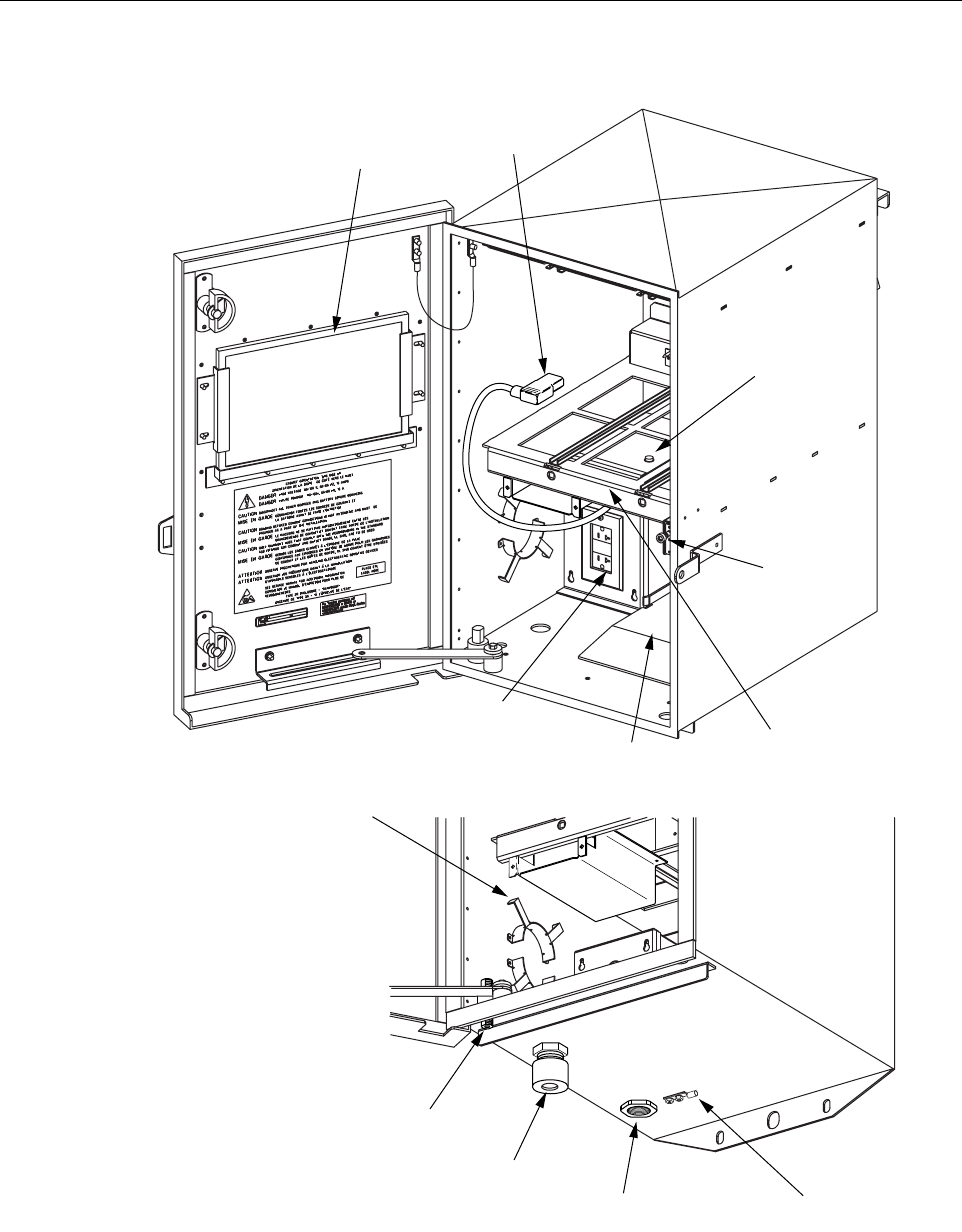
Figure 2-4. Remote Unit Cabinet User Interface
BOTTOM VIEW
OF CABINET
(7) GFCI OUTLET
(4) DOOR
SWITCH
(1) AIR INLET FILTER
(2) AC POWER
CORD
(3) CIRCUIT BREAKER
RESET SWITCH
(5) MODULE MOUNTING
SHELF
(6) BATTERY TRAY
(8) FIBER SLACK
SPOOL
(9) ANTENNA
CONNECTOR
(10) FIBER CABLE
CONNECTOR (11) THREADS FOR
AC CONDUIT FITTING (12) GROUNDING LUG
16793-A
FCC ID: F8I-DVLRCSSMR Class II Permissive Change
Manual - Part 2

ADCP-75-134 • Issue A • April 2002 • Section 2: Description
Page 2-12
©2002, ADC Telecommunications, Inc.
4 SPECTRUM TRANSPORT MODULE
The Spectrum Transport Module (STM), shown in Figure 2-5,serves as the handset servicing
device for the Digivance LRCS. The STM provides the following basic functions:
• Provides RF transmit and receive connections to the Dual Duplexer/Splitter.
• Provides optical connections to the HU.
•Convertsthe digitized forward path optical signal to adigitized RF signal.
•Convertsthe digitized RF signal to acomposite RF signal.
• Digitizes the reverse path composite RF signal.
•Convertsthe digitized reverse path RF signal to adigitized optical signal.
• Provides an RS-232 connection to alocal EMS computer.
• Transports alarm, control, and monitoring information via the optical fibers.
• Provides an AC power connection and battery power connection.
• Provides external alarm connection.
Table 2-2. Remote Unit Cabinet User Interface
REF
NO DEVICE FUNCTIONAL DESCRIPTION
1Airinlet filter A reusable filter that prevents the entry of dirt particles when out-
side air is pulled into the cabinet for cooling.
2ACpower cord Provides AC power to the STM.
3 Circuit breaker reset switch Used to reset the battery heater circuit following correction of an
overcurrent condition.
4Doorswitch Indicates to the fault detection and alarm reporting system if the
cabinet door is open (major alarm) or closed.
5 Module mounting shelf Provides amounting point for the STM and LPA modules.
6Batterytray Provides amounting point for the back-up battery (when used).
7120Vac GFCI outlet
(standard)
Standard 120 Vac GFCI outlet for connecting AC power tools or
test equipment.
8Fiberslack spool Provides astorage place for excess fiber pigtail slack.
9 Antenna connector Provides lightning surge protection for the antenna connection.
10 Fiber cable connector Provides both an entry point and strain relief for the fiber optic
cable.
11 3/4-inch NPT threaded hole Provides aconnection point for a3/4-inch AC conduit fitting.
12 Grounding lug Provides aconnection point for an external grounding cable.
ADCP-75-134 • Issue A • April 2002 • Section 2: Description
Page 2-13
©2002, ADC Telecommunications, Inc.
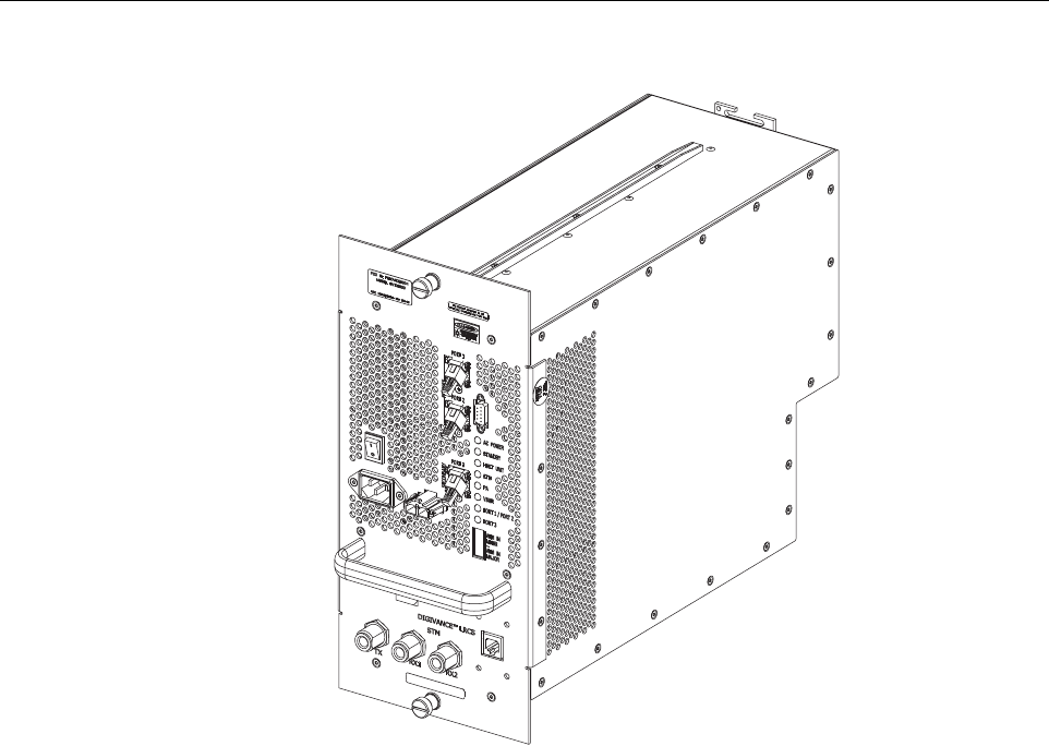
Figure 2-5. Spectrum Transport Module
4.1 Primary Components
The STM consists of an electronic circuit board assembly, power supply, and fan assembly that
are mounted within apowder-coated sheet metal enclosure. The metal enclosure provides a
mounting point for the electronic components and controls RF emissions. Except for the fan
unit, the electronic components are not user replaceable. The STM is designed for use within
the RU cabinet. Except for the LPA interface connector, all controls, connectors, indicators, and
switches are mounted on the STM front panel for easy access. Acarrying handle is provided on
the front of the STM to facilitate installation and transport.
4.2 Mounting
The STM mounts on ashelf within the RU cabinet. Arunner on the bottom of the STM meshes
with atrack on the mounting shelf. The runner and track guide the STM into the installed
position. The electrical interface between the STM and LPA is supported by aD-sub female
connector located on the rear side of the STM. Acorresponding D-sub male connector mounted
at the rear of the RU cabinet mounting shelf mates with the STM connector. Captive screws are
provided for securing the STM to the mounting shelf.
17620-A.eps

ADCP-75-134 • Issue A • April 2002 • Section 2: Description
Page 2-14
©2002, ADC Telecommunications, Inc.
4.3 Fault Detection and Alarm Reporting
The STM detects and reports the following faults: remote unit fault, optical fault, power fault,
temperature fault, power amplifier fault, and external (door open) fault. Various front panel
Light Emitting Diode (LED) indicators turn from green to red or yellow if afault is detected.
The status of the STM, the alarm state (major or minor), and other more detailed alarm
information is summarized and reported over the fiber optic link to the HU and also over the
service interface. In addition, the alarm state of the HU is received over the fiber optic link and
reported to the service interface. This detailed information may be accessed remotely through
the NOC/NEM interface or locally through the EMS software MI.
4.4 RF Signal Cable Connections
Transmit and receive coaxial cable connections between the STM and the DDS are supported
through three N-type female connectors. The TX connector is used for the RF forward path
transmit signal connection. The RX1 connector is used for the RF reverse path primary receive
signal connection. The RX2 connector is used for the RF reverse path diversity receive signal
connection. All coaxial jumper cables are provided with the DDS.
4.5 RF Signal Level Adjustment
The STM is equipped with adigital attenuator for adjusting the signal level of the forward path
RF output signal. The remote forward path attenuator adjusts the level of the output RF signal
at the RU antenna port and will add from 0to 20 dB of attenuation to the output signal level.
The attenuator can be set in 1dB increments. The attenuator is software controlled and is
adjusted through the NOC/NEM interface or the EMS software MI.
4.6 Optical Signal Connections
Optical connections between the STM and the HU are supported through three SC-type optical
connector ports. Port 1is used for the forward path optical signal connection. Port 2is used for
the reverse path primary optical signal connection. Port 3is used for the reverse path diversity
optical signal connection.
4.7 Service Interface Connection
The service interface connection between the STM and alocal laptop computer loaded with the
EMS software is supported by asingle DB-9 female connector. The service interface connector
provides an RS-232 DTE interface. The STM service interface connector supports local
communications with both the STM and the corresponding HU.
4.8 Powering
The STM is powered by 120 or 240 Vac (50 or 60 Hz) power which is supplied through athree-
conductor AC power cord. The power cord is provided with the RU cabinet. One end of the cord
is hard-wired to the AC power outlet box and the other end is terminated with amolded-on plug
ADCP-75-134 • Issue A • April 2002 • Section 2: Description
Page 2-15
©2002, ADC Telecommunications, Inc.
cap. The power cord connects to a3-wire AC cord connector mounted on the STM front panel.
Aswitch on the STM front panel provides AC power On/Off control.
The STM (and the connected LPA) may be powered by a24 Vdc back-up battery system which
is available as an accessory kit. Aconnector is provided on the STM front panel for connecting
the wiring harness for the back-up battery system.
4.9 Cooling
Continuous air-flow for cooling is provided by asingle fan mounted on the rear side of the STM
housing. An alarm is provided that indicates if ahigh temperature condition (>50º C/122º F)
occurs. If the temperature falls below 32º F(0º C), the fan automatically shuts off. The fan may
be field replaced if it fails.
4.10 User Interface
The STM user interface consists of the various connectors, switches, and LEDs that are
provided on the STM front panel. The STM user interface points are indicated in Figure 2-6 and
described in Table 2-3.
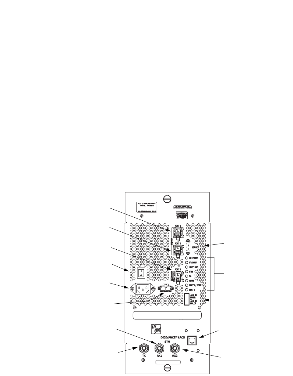
Figure 2-6. Spectrum Transport Module User Interface
17621-A
(4) ON/OFF
SWITCH
(5) AC POWER
CONNECTOR
(6) DC POWER
CONNECTOR
(1) PORT 1
CONNECTOR
(2) PORT 2
CONNECTOR
(3) PORT 3
CONNECTOR
(7) SERVICE
CONNECTOR
(8-15) LED
INDICATORS
(16) ALARM
CONNECTOR
(17) POWER
MONITOR
CONNECTOR
(18) PRIMARY
RECEIVER
CONNECTOR
(19) DIVERSITY
RECEIVER
CONNECTOR
(20) TRANSMITTER
CONNECTOR

ADCP-75-134 • Issue A • April 2002 • Section 2: Description
Page 2-16
©2002, ADC Telecommunications, Inc.
Table 2-3. Spectrum Transport Module User Interface
REF
NO
USER INTERFACE
DESIGNATION DEVICE FUNCTIONAL
DESCRIPTION
1PORT1SCconnector
(single-mode) Connection point for the forward path optical
fiber.
2PORT2SCconnector
(single-mode) Connection point for the reverse path primary
optical fiber.
3PORT3
(diversity unit only) SC connector
(single-mode) Connection point for the reverse path diversity
optical fiber.
41/0 On/Offrocker
switch Provides AC power on/off control.
5Nodesignation 3-wire AC power
cord connector Connection point for the AC power cord.
6Nodesignation 2- wire DC power
cord connector Connection point for the back-up battery power
cord.
7 SERVICE DB-9 connector
(female) Connection point for the RS-232 service inter-
face cable.
8ACPOWER Multi-colored LED
(green/red)
Indicates if the STM is powered by the AC power
source (green) or the back-up battery system
(red). See Note.
9 STANDBY Multi-colored LED
(green/yellow/red)
Indicates if the system is in the Normal state (off)
Standby state (blinking green), Test state (blink-
ing red), or Program Load state (blinking yel-
low). See Note.
10 HOST UNIT Multi-colored LED
(green/yellow/red)
Indicates if no alarms (green), aminor alarm
(yellow), or amajor alarm (red) is detected at the
HU. See Note.
11 STM Multi-colored LED
(green/yellow/red)
Indicates if the STM is normal (green) or faulty
(red). See Note.
12 PA Multi-colored LED
(green/yellow/red)
Indicates if the power amplifier is normal
(green), over temperature (yellow), has afan fail-
ure (yellow), or is faulty (red). See Note.
13 VSWR Multi-colored LED
(green/yellow/red)
Indicates if the forward path VSWR is above
(red) or below (green) the fault threshold.
14 PORT 1/PORT 2 Multi-colored LED
(green/yellow/red)
Indicates if the forward path optical signal
received from the HU is normal (green), if no sig-
nal is detected (red), or if errors are detected
(red). See Note.
15 PORT 3
(diversity unit only)
Multi-colored LED
(green/yellow)
Indicates if the diversity reverse path optical sig-
nal received by the HU is normal (green), if no
signal is detected (yellow), or if errors are
detected (yellow). See Note.
16 ALARM IN MINOR
ALARM IN MAJOR
Screw-type terminal
connector (14–26
AWG)
Connection point for two external alarm inputs.
The door-open switch lead wires are typically
connected to the major alarm terminals.
17 No designation RJ-45 jack Connection point for the power monitor cable.
ADCP-75-134 • Issue A • April 2002 • Section 2: Description
Page 2-17
©2002, ADC Telecommunications, Inc.
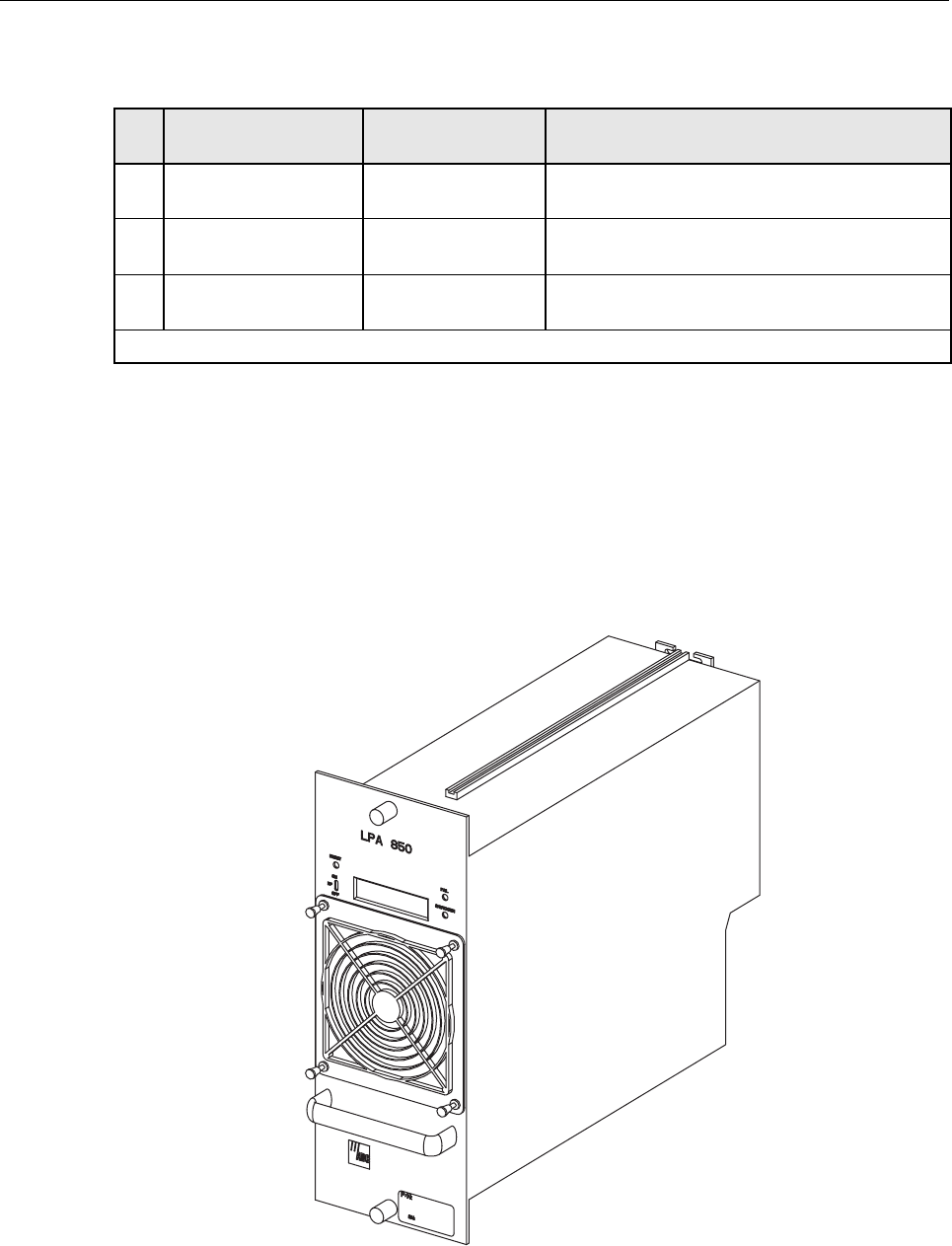
5 LINEAR POWER AMPLIFIER
The Linear Power Amplifier (LPA), shown in Figure 2-7,works is conjunction with the STM to
amplify the forward path RF output signal. The STM is interfaced with the LPA through the D-
sub connectors and wiring harness located at the rear of the RU cabinet. The RF signal is passed
to the LPA for amplification and then passed back to the STM for output via the STM’s
transmitter (TX) port. The STM also supplies DC power to the LPA through the same interface.
Figure 2-7. Linear Power Amplifier
18 TX N-type female RF
coaxial connector Connection point for the DDS forward path
transmitter cable.
19 RX1 N-type female RF
coaxial connector Connection point for the DDS reverse path pri-
mary receiver cable.
20 RX2 N-type female RF
coaxial connector Connection point for the DDS reverse path diver-
sity receiver cable.
Note: Amore detailed description of LED operation is provided in Section 5.
Table 2-3. Spectrum Transport Module User Interface, continued
REF
NO
USER INTERFACE
DESIGNATION DEVICE FUNCTIONAL
DESCRIPTION
16798-A

ADCP-75-134 • Issue A • April 2002 • Section 2: Description
Page 2-18
©2002, ADC Telecommunications, Inc.
5.1 Primary Components
The LPA consists of several electronic circuit board assemblies and two fan assemblies that are
mounted within apowder-coated sheet metal enclosure. The metal enclosure provides a
mounting point for the electronic components and controls RF emissions. Except for the fan
units, the electronic components are not user replaceable. The LPA is designed for use within
the RU cabinet. Except for the STM interface connector, all controls, indicators, and switches
are mounted on the LPA front panel for easy access. Acarrying handle is provided on the front
of the LPA to facilitate installation and transport.
5.2 Mounting
The LPA mounts on ashelf within the RU cabinet. Runners on the top and bottom of the LPA
mesh with tracks on the mounting shelf. The runners and tracks guide the LPA into the installed
position. The electrical interface between the STM and LPA is supported by aD-sub female
connector located on the rear side of the LPA. Acorresponding D-sub male connector mounted
at the rear of the RU cabinet mounting shelf mates with the LPA connector. Captive screws are
provided for securing the LPA to the mounting shelf.
5.3 Fault Detection and Alarm Reporting
The LPA in conjunction with the STM detects and reports the following faults: power amplifier
fault, output power fault, temperature fault, and fan fault. Various Light Emitting Diode (LED)
indicators located on the front panels of both the STM and LPA turn from green to red or yellow
if an LPA fault is detected. In addition, adigital display located on the LPA front panel provides
various fault messages. The status of the LPA, the alarm state (major or minor), and other more
detailed information is summarized and reported (by the STM) over the fiber optic link to the
HU and also to the service interface. This detailed information may be accessed remotely
through the NOC/NEM interface or locally through the EMU software MI.
5.4 Powering
The LPA is powered by various DC voltages which are supplied by the STM over the electrical
interface provided by the D-sub connectors and wiring harness mounted within the RU cabinet.
5.5 Cooling
Continuous air-flow for cooling is provided by apair of fans mounted at the front and the rear
side of the LPA housing. The front fan pulls cool air into the module and the rear fan exhausts
heated air out of the module. An alarm is provided that indicates if ahigh temperature condition
(>50º C/122º F) occurs or if afan failure occurs. Either fan may be field replaced if it fails.
5.6 User Interface
The LPA user interface consists of the various LEDs, message displays, and switches that are
provided on the LPA front panel. The LPA user interface points are described in Table 2-4 and
indicated in Figure 2-8.
ADCP-75-134 • Issue A • April 2002 • Section 2: Description
Page 2-19
©2002, ADC Telecommunications, Inc.
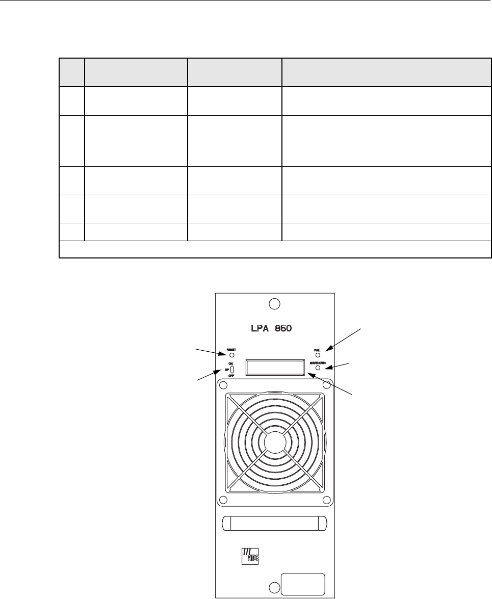
Figure 2-8. Linear Power Amplifier User Interface
Table 2-4. Linear Power Amplifier User Interface
REF
NO
USER INTERFACE
DESIGNATION DEVICE FUNCTIONAL
DESCRIPTION
1 RESET Momentary contact
push button switch Momentarily pressing the switch push button
clears all alarms and restarts the amplifier
2RFON OFF 2-position switch Placing the switch in the OFF position puts the
LPA in astandby state with RF output disabled.
Placing the switch in the ON position puts the
LPA in the normal state with RF output enabled.
3FAIL LEDindicator
(yellow) Indicates the LPA is normal (off) or faulty
(yellow).
4 SHUTDOWN LED indicator (red) Indicates the LPA is in service (off) or shutdown
(red).
5Nodesignation Digital display Provides status and alarm messages. See Note.
Note: Amore detailed description of the digital display messages is provided in Section 5.
(1) RESET
SWITCH
(2) RF ON/OFF
SWITCH
(3) FAIL
LED
(4) SHUTDOWN
LED
(5) DIGITAL
DISPLAY
16804-A
ADCP-75-134 • Issue A • April 2002 • Section 2: Description
Page 2-20
©2002, ADC Telecommunications, Inc.
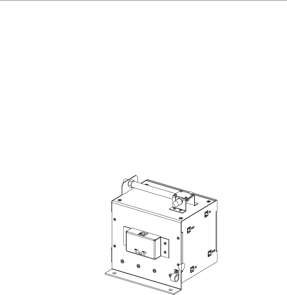
6 DUAL DUPLEXER/SPLITTER
The Dual Duplexer/Splitter (DDS), shown in Figure 9, serves as an interface device between the
STM and the primary and diversity antennas. The DDS provides the following basic functions:
• Provides aforward path RF transmit signal connection for the STM.
• Splits the forward path RF transmit signal for distribution to the two duplex filters.
• Provides aprimary and diversity reverse path RF receive signal connection for the STM.
• Duplexes the forward transmit and primary reverse path signals for connection to the
primary antenna.
• Duplexes the forward transmit and diversity reverse path signals for connection to the
diversity antenna.
• Provides RF signal connections to the primary and diversity remote antennas
• Provides switch selectable power level monitoring of the transmit signal at the primary
and diversity antenna ports.
Figure 2-9. Dual Duplexer/Splitter
6.1 Primary Components
The DDS consists of an RF signal splitter, apair of duplex filters, RF power monitor interface,
and asheet metal enclosure with integral mounting bracket. The DDS is designed for use within
the RU cabinet. The sheet metal enclosure provides amounting point for the DDS components
and ameans for securing the DDS within the cabinet. Cable connectors are mounted on the top,
front, left, and right sides of the DDS. The RF power monitor interface is mounted on the front
side of the DDS for easy access. The various components of the DDS are not user replaceable.
17622-A

ADCP-75-134 • Issue A • April 2002 • Section 2: Description
Page 2-21
©2002, ADC Telecommunications, Inc.
6.2 Mounting
The DDS mounts within the RU cabinet just below the STM and LPA modules and in front of
the battery tray. Screws are provided with the DDS for securing the DDS mounting bracket to
the bottom of the cabinet.
6.3 Transmit Signal Connections
The transmit signal connection to the DDS is through the RF signal splitter which is mounted on
top of the DDS enclosure. The splitter is equipped with N-type female connectors for both the
input and the output connections. The forward path transmit signal is supplied to the splitter
input connector over acoaxial jumper cable. The signals from the splitter output connectors are
supplied to the duplex filters. The duplex filters are equipped with SMA-type female connectors
for the transmit signal connections. Apair of hybrid-type coaxial jumper cables are used to link
the splitter output connectors to the duplexer input connectors. All cables required for the
transmit signal connections are provided with the DDS.
6.4 Receive Signal Connections
The receive signal connections to the DDS are through apair of SMA-type female connectors.
Aseparate connector is mounted on each duplex filter. The primary receive signal is supplied to
duplexer 1. The diversity receive signal is supplied to duplexer 2. Apair of hybrid-type coaxial
jumper cables are used to link the STM receiver connectors to the duplexer receive connectors.
All cables required for the receive signal connections are provided with the DDS.
6.5 Antenna Cable Connections
The antenna cable connections to the DDS are through apair of N-type female connectors. A
separate connector is mounted on each duplex filter. Duplexer 1connects to the primary (1)
antenna. Duplexer 2connects to the diversity (2) antenna. The DDS does not connect directly to
the antennas but instead connects to apair of lightning protectors that are mounted on the
bottom of the RU cabinet (see Section 3.5). Apair of coaxial jumper cables are provided
(included with the DDS) for connecting the duplexer connectors to the lightning protectors.
6.6 RF Power Level Monitor
The DDS provides apair of LED indicators that show when the antenna ports are being
monitored for the RF power level and also aswitch for selecting which port (ANT 1or ANT 2)
will be monitored or if both ports will be monitored. Each LED indicator turns on (green) to
indicate when the monitor function is active and off to indicate when the monitor function is
inactive. The power monitor switch is used to manually select whether both antenna ports will
be monitored (switch in center position) or if only one port will be monitored (switch in either
ANT 1or ANT 2position). When both ports are monitored, the STM will monitor one port for
10 seconds and then monitor the other port for ten seconds.
ADCP-75-134 • Issue A • April 2002 • Section 2: Description
Page 2-22
©2002, ADC Telecommunications, Inc.
6.7 User Interface
The DDS user interface consists of the various connectors, LEDs, and switches that are
provided on the exterior of the DDS. The DDs user interface points are indicated in Figure 2-10
and described in Table 2-5.
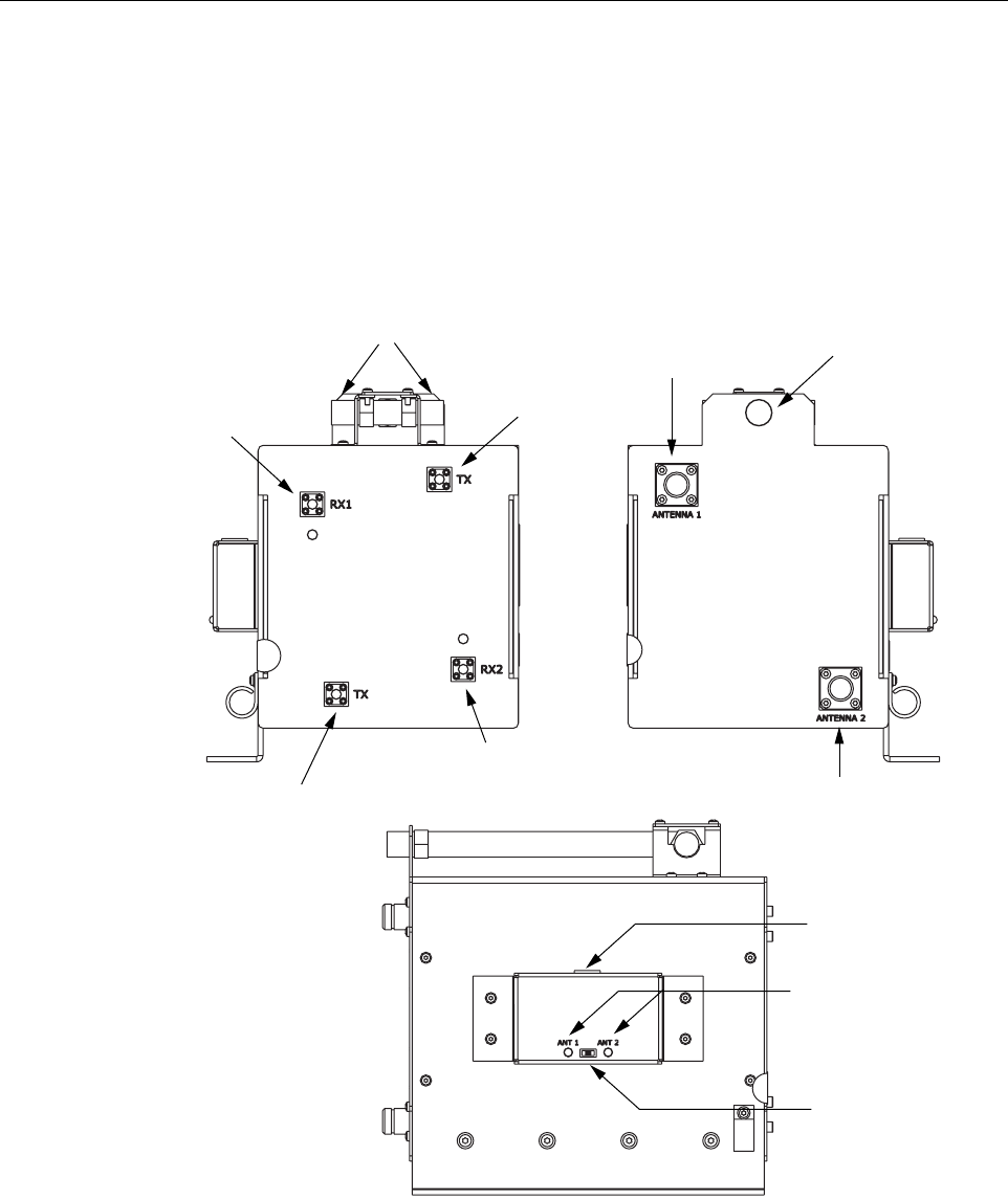
Figure 2-10. Dual Duplexer/Splitter User Interface
FRONT
RIGHT LEFT
(1) DUPLEXER 1
RECEIVE
CONNECTOR
(3) DUPLEXER 1
TRANSMIT
CONNECTOR
(7) DUPLEXER 1
ANTENNA
CONNECTOR
(8) DUPLEXER 2
ANTENNA
CONNECTOR
(2) DUPLEXER 2
TRANSMIT
CONNECTOR
(4) DUPLEXER 2
TRANSMIT
CONNECTOR
(6) SPLITTER TRANSMIT
INPUT CONNECTOR
(5) SPLITTER TRANSMIT
OUTPUT CONNECTORS
(9) POWER MONITOR
CABLE CONNECTOR
(10 & 11) POWER
MONITOR LEDS
(12) POWER
MONITOR SWITCH
17635-A

ADCP-75-134 • Issue A • April 2002 • Section 2: Description
Page 2-23
©2002, ADC Telecommunications, Inc.
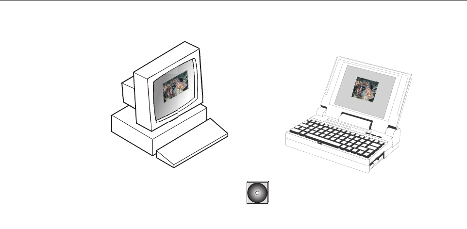
7 DIGIVANCE ELEMENT MANAGEMENT SYSTEM
The Digivance Element Management System (EMS) is anetwork management tool that provides
control and monitoring functions for the Digivance LRCS system. The EMS is used to provision
and configure new systems for operation, set system operating parameters, get system alarm and
status messages, and upgrade the system software. The EMS supports both local control by an
on-site service technician and remote control by aNetwork Operations Center (NOC).
7.1 Primary Components
The EMS, shown in Figure 2-11,consists of aPC-type desk-top computer (not provided) that is
loaded with the EMS software. The EMS software is stored on aCD-ROM that is shipped with
the HU. The EMS software must be installed on the EMS computer along with the Java 2
Version 1.3.1 Runtime Environment software which is also provided. Installation consists of
inserting the CD-ROM into the computer’s CD-ROM drive and then running the software install
programs. This places the Java 2Runtime Environment and EMS software files in assigned
folders on the computer’s hard drive.
Table 2-5. Dual Duplexer/Splitter User Interface
REF
NO
USER INTERFACE
DESIGNATION DEVICE FUNCTIONAL
DESCRIPTION
1RX1 SMAconnector
(female) Connection point for the reverse path receive
coaxial cable.
2RX2 SMAconnector
(female) Connection point for the reverse path diversity
receive coaxial cable.
3TX SMAconnector
(female) Connection point for the duplexer 1forward path
transmit coaxial cable.
4TX SMAconnector
(female) Connection point for the duplexer 2forward path
transmit coaxial cable.
5Nodesignation N-type connector
(female) Connection point for the duplexer 1forward path
transmit coaxial cable.
6Nodesignation N-type connector
(female) Connection point for the duplexer 2forward path
transmit coaxial cable.
7 ANTENNA 1 N-type connector
(female) Connection point for the antenna 1(primary)
coaxial cable.
8 ANTENNA 2 N-type connector
(female) Connection point for the antenna 2(diversity)
coaxial cable
9Nodesignation RJ-45 connector
(female) Connection point for the power monitor cable.
10 ANT 1LEDindicator
(green) Indicates if antenna port 1is being monitored
(green) or not (off).
11 ANT 2LEDindicator
(green) Indicates if antenna port 2is being monitored
(green) or not (off).
12 No designation 3-position switch Switch to select whether antenna port 1(ANT 1),
antenna port 2(ANT 2), or both antenna ports
(center) will be monitored.
ADCP-75-134 • Issue A • April 2002 • Section 2: Description
Page 2-24
©2002, ADC Telecommunications, Inc.
Figure 2-11. Alarm Network Unit
The EMS software may also be installed on aPC-type lap-top computer (not provided). Alap-
top version of the EMS computer can be used as aportable network management tool for
service and maintenance purposes. Alaptop EMS can be connected temporarily to asystem to
enter the initial configuration data or to trouble-shoot problems and then removed when the task
is completed. Permanent control and monitoring functions would be provided by the desk-top
EMS computer.
7.2 Service Interface Connection
The service interface connection between the EMS computer and the HU or RU requires that
the EMS computer be equipped with aDB-9 connector that is configured to provide an RS-232
DCE interface. Astraight-through RS-232 interface cable (accessory item) equipped with a
male DB-9 connector on one end and aPC-compatible connector on the other end is required to
link the EMS computer to the HU. When multiple HUs are networked together, the EMS
computer may be connected to the service connector on any one of the networked HUs.
7.3 NOC Interface Connection
The NOC interface connection between the EMS computer and the NOC requires that the EMS
computer be equipped with aconnector that is configured to provide an RS-232 ASCII
interface. The link between the EMS computer and the NOC would generally be supported by a
data network or dial-up modem. Cables and equipment (not provided) to support the RS-232
interface connection between the EMS computer and the data network or dial-up modem are
required.
CD-ROM WITH EMS
SOFTWARE
OR
PLUS
16803-A
ADCP-75-134 • Issue A • April 2002 • Section 2: Description
Page 2-25
©2002, ADC Telecommunications, Inc.
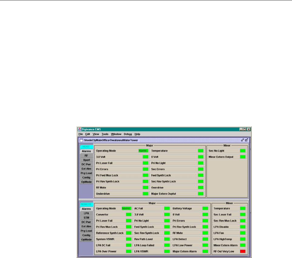
7.4 EMS Software User Interface
The EMS software provides two user interfaces: the Maintenance Interface (MI) and the
Network Operation Center-Network Element Manager (NOC/NEM) interface. Both interfaces
provide essentially the same functionality except only the MI can upgrade the HU/RU system
with new system software. In addition, only the NOC/NEM interface can record and playback
alarm data.
The MI is agraphical user interface that is presented at the EMS computer or on alaptop
computer. The MI is used for local control and monitoring operations. The MI presents aseries
of displays and screens, such as the one shown in Figure 2-12,to provide the user with alarm
and status information and to allow the user to set various operating parameters.
Figure 2-12. EMS Maintenance Interface Host/Remote Display
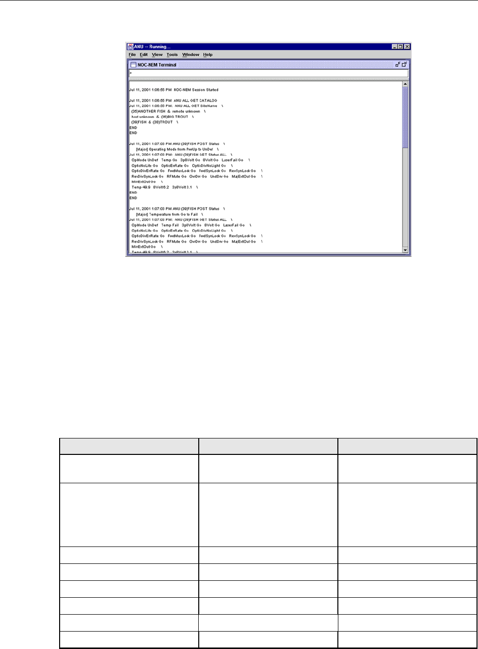
The NOC/NEM interface is acommand line interface that is presented at an NOC terminal. The
NOC/NEM interface is used for remote control and monitoring operations. The NOC/NEM
interface consists of ASCII text strings that are input as SET or GET commands which are
followed by the action or information required. Atext string response is received from the
specified system or systems to confirm the requested action or to report the requested
information. Examples of several typical NOC-MEM interface commands and the responses
received are shown in Figure 2-13.The NOC/NEM interface requires only aVT100 terminal/
emulator or aPC-type computer that is loaded with acommunication software such as
Procomm Plus. While primarily intended for use at the NOC, the NOC/NEM interface
commands may also be input from the EMS computer.
ADCP-75-134 • Issue A • April 2002 • Section 2: Description
Page 2-26
©2002, ADC Telecommunications, Inc.
Figure 2-13. NOC/NEM Interface Typical Commands
8 SPECIFICATIONS
Refer to Table 2-6 for the Digivance LRCS system typical specifications. All specifications
apply after afive minute warm-up period.
Table 2-6. System Typical Specifications
PARAMETER SPECIFICATION REMARKS
Optical - All Units
Fiber type 9/125, single-mode, dark
Number of fibers required
Non-diversity with WDM
Diversity with WDM
Non-diversity without WDM
Diversity without WDM
1
2
2
3
The wavelength division multi-
plexer (WDM) is an accessory
item.
Forward path wavelength 1550 ±20 nm
Reverse path wavelength 1310 ±20 nm
Diversity path wavelength 1310 ±20 nm
Optical budget 17 dB typical
System optical maximum –7 dBm
Optical connectors Industry standard SC Host, remote, and WDM

ADCP-75-134 • Issue A • April 2002 • Section 2: Description
Page 2-27
©2002, ADC Telecommunications, Inc.
RF Forward Path - SMR 800 MHz
System bandwidth 15 MHz
Frequency range 851 to 866 MHz
Gain of host/remote link 80.85 dB at band center and
room temperature Includes power amplifier.
Gain flatness 1.5 dB across freq. range
1dB variation across any 1.25
MHz channel
Gainvariation 1.5 dBovertempandunit-to-unit
Gain adjustment Software adjustable in 20 steps
of 1dB
Out-of-band rejection –40 dB bandwidth <30 MHz
Propagation delay < 6µsmaximum Excludes fiber delay.
Variable propagation delay
adjustability Software adjustable in 1µsincre-
ments over a 0 to 63 µsrange
Spurious free dynamic range –60 dBc
Tx peak to average 10 dB
Intermodulation –55 dBc at remote output
Maximum composite RF input
signal level –20 to –40 dBm, adjustable in 1
dB increments
(The host requires a–40 dB input
signal level)
–40 dBm with host attenuator at
0dB
–20 dBm with host attenuator at
20 dB
Txpathinsertionloss 6.0 dB
Output power 50 Watts at power amplifier out-
put
12 Watts (40.85 dBm) at each
DDS antenna port
RF Reverse Path - SMR 800 MHz
System bandwidth 15 MHz
Frequency range 806 to 821 MHz
Gain 30 dB at band center
Gain flatness 1.5 dB across frequency range
<1dB variation across any 1.25
MHz channel
Gain variation 3 dB over temperature and unit-
to-unit
Out-of-band rejection –40 dB bandwidth <30 MHz
Propagation delay < 6µsmaximum Excludes fiber delay
Variable propagation delay
adjustability Software adjustable in 1µsincre-
ments over a 0 to 63 µsrange
Table 2-6. System Typical Specifications, continued
PARAMETER SPECIFICATION REMARKS

ADCP-75-134 • Issue A • April 2002 • Section 2: Description
Page 2-28
©2002, ADC Telecommunications, Inc.
Intermodulation –62 dBc
System noise figure 8 dB
Composite RF output level –10 to –30 dBm, adjustable in 20
steps of 1 ± 0.25 dB increments With –40 dBm maximum com-
posite input signal level at the
remote unit.
Dynamic range 70 dB (two carriers)
Physical/Environmental/
Electrical - Host Unit
Dimensions (H×W×D) 3.5 × 17.2 × 15.3 inches
(89 ×437 ×389 mm) Dimension for width does not
include the mounting brackets
which can be installed for either
19- or 23-inch racks.
Mounting 19- or 23-inch rack EIA or WECO
Weight 18 lbs. (8.2 kg)
Weather resistance Indoor installation only
Operating temperature 0º to 50º C(32º to 122º F)
Storage temperature –40º to 70º C(–40º to 158ºF)
Humidity 10% to 90% No condensation
External alarm connector Screw-type terminals NO and NC relay contacts
DC power connector Screw-type terminal strip
RF coaxial cable connectors N-type (female)
Service connector DB-9 (female) RS-232 DTE interface
CAN connectors RJ-45 jack
Power input ± 24 or ±48 Vdc
Power consumption 55 watts
Current rating 1 Amp at –48 Vdc
Reliability at 25ºC MTBF 80,000 hours Excluding fans
Physical/Environmental/
Electrical - Remote Unit
Cabinet dimensions (H×W×D) 28.4 × 17.4 × 24.9 inches
(721 ×442 ×632 mm)
Mounting Wall or pole Pole mounting requires the pole
mount kit. (accessory)
Weight 120 lbs (54.4 kg) Includes modules but not battery
Weather resistance NEMA-3R, removable dust filter
Operating temperature –30º to 50º C(–22º to 122º F)
Storage temperature –40º to 70º C(–40º to 158ºF)
Humidity 10% to 90% No condensation
External alarm connector Screw-type terminals External alarm inputs
Table 2-6. System Typical Specifications, continued
PARAMETER SPECIFICATION REMARKS

ADCP-75-134 • Issue A • April 2002 • Section 2: Description
Page 2-29
©2002, ADC Telecommunications, Inc.
AC power connection 3/4- or 1/2-inch conduit Per local code or practice.
Antenna cable connector N-type (female)
Fiber optic cable size 0.375 to 0.875 inch (10 to 22
mm) diameter cable 9/125, single-mode, dark
Lightning protection 20 kA IEC 1000-4-5 8/20 µs
waveform
Service connector DB-9 (female) RS-232 DTE interface
Battery backup operation 1 hour
Power input 120 or 240 VAC , 50 or 60 Hz Operation on 240 VAC requires
removal of the 120 VAC outlet.
Power consumption 1200 watts
Current rating 9 Amps at 120 Vac
Reliability at 25ºC MTBF 50,000 hours Excluding fans, battery, and air
filter
Table 2-6. System Typical Specifications, continued
PARAMETER SPECIFICATION REMARKS

ADCP-75-134 • Issue A • April 2002 • Section 2: Description
Page 2-30
©2002, ADC Telecommunications, Inc.
Blank