ADC Telecommunications DVLRCSSMR Digivance Long Range Coverage Solution SMR System User Manual 75134
ADC Telecommunications Inc Digivance Long Range Coverage Solution SMR System 75134
Contents
Part 3 new manual

ADCP-75-134 • Issue A • April 2002 • Section 3: Host Unit Installation
Page 3-1
©2002, ADC Telecommunications, Inc.
SECTION 3: HOST UNIT INSTALLATION
1 BEFORE STARTING INSTALLATION . . . . . . . . . . . . . . . . . . . . . . . . . . . . . . . . . . . . . . . . . . . . . . . . . . . . . . . . . .3-1
1.1 Tools and Materials . . . . . . . . . . . . . . . . . . . . . . . . . . . . . . . . . . . . . . . . . . . . . . . . . . . . . . . . . . . . . . .3-1
1.2 Unpacking and Inspection. . . . . . . . . . . . . . . . . . . . . . . . . . . . . . . . . . . . . . . . . . . . . . . . . . . . . . . . . . .3-2
2 OSP FIBER CABLE INSTALLATION GUIDELINES . . . . . . . . . . . . . . . . . . . . . . . . . . . . . . . . . . . . . . . . . . . . . . . . . .3-2
3 WDM MOUNTING PROCEDURE (OPTIONAL ACCESSORY) . . . . . . . . . . . . . . . . . . . . . . . . . . . . . . . . . . . . . . . . . . .3-4
4 HU MOUNTING PROCEDURE . . . . . . . . . . . . . . . . . . . . . . . . . . . . . . . . . . . . . . . . . . . . . . . . . . . . . . . . . . . . . . .3-6
5 CHASSIS GROUND CONNECTION . . . . . . . . . . . . . . . . . . . . . . . . . . . . . . . . . . . . . . . . . . . . . . . . . . . . . . . . . . . .3-8
6 COAXIAL CABLE CONNECTIONS. . . . . . . . . . . . . . . . . . . . . . . . . . . . . . . . . . . . . . . . . . . . . . . . . . . . . . . . . . . . .3-8
7 OPTICAL CONNECTIONS. . . . . . . . . . . . . . . . . . . . . . . . . . . . . . . . . . . . . . . . . . . . . . . . . . . . . . . . . . . . . . . . . 3-10
7.1 Optical Connections Without WDM. . . . . . . . . . . . . . . . . . . . . . . . . . . . . . . . . . . . . . . . . . . . . . . . . . . . 3-10
7.2 Optical Connections With WDM . . . . . . . . . . . . . . . . . . . . . . . . . . . . . . . . . . . . . . . . . . . . . . . . . . . . . . 3-11
8 CONTROLLER AREA NETWORK CONNECTIONS . . . . . . . . . . . . . . . . . . . . . . . . . . . . . . . . . . . . . . . . . . . . . . . . . 3-13
9 SERVICE INTERFACE CONNECTION . . . . . . . . . . . . . . . . . . . . . . . . . . . . . . . . . . . . . . . . . . . . . . . . . . . . . . . . . 3-14
10 EXTERNAL ALARM SYSTEM CONNECTIONS . . . . . . . . . . . . . . . . . . . . . . . . . . . . . . . . . . . . . . . . . . . . . . . . . . . 3-15
11 DC POWER CONNECTIONS . . . . . . . . . . . . . . . . . . . . . . . . . . . . . . . . . . . . . . . . . . . . . . . . . . . . . . . . . . . . . . . 3-16
_________________________________________________________________________________________________________
1 BEFORE STARTING INSTALLATION
This section provides the installation procedures for the HU, the WDM mounting shelf
(accessory item), and the WDM (accessory item). Installation of the RU cabinet and RU
electronic modules may proceed separately from installation of the HU. The installation
procedures for the single band remote cabinet are provided in the Digivance Long-Range
Coverage Solution Single Band Remote Cabinet Mounting Instructions (ADCP-75-117) which
are shipped with the cabinet. The installation procedures for the STM and LPA electronic
modules and Dual Duplexer/Splitter are provided in the Digivance Long-Range Coverage
Solution Remote Unit Installation Instructions which are shipped with the STM. When all units
of the Digivance LRCS have been installed, refer to Section 4of this manual for the system
turn-up and test procedures.
Before beginning the installation, review the system design plan with the system engineer.
Make sure each equipment installation site is identified and located and all cable runs are
mapped out.
1.1 Tools and Materials
The following tools are required to complete the procedures in this section:
•Boxcutter
• Pencil or scribe
•Mediumsize flat-bladed screwdriver
• Phillips screwdriver (#2)
Content Page
FCC ID: F8I-DVLRCSSMR Class II Permissive Change
Manual - Part 3

ADCP-75-134 • Issue A • April 2002 • Section 3: Host Unit Installation
Page 3-2
©2002, ADC Telecommunications, Inc.
•TORXscrewdriver (T20 bit)
• Pliers
•Wirecutters
•Wirestripper
• Tool kit for attaching N-type male connectors to coaxial cable
• Multimeter
•Opticalpower meter
• Laser light source
The following materials are required to complete the procedures in this section:
• #18 AWG (1.0 mm) insulated stranded copper wire (for chassis grounding wire)
• #18 AWG (1.0 mm) red and black insulated copper wire (for DC power wires)
• Category 3or 5cable (for external alarm system wires)
•#6ring terminal (1) for #18 wire (for chassis ground wire connection)
•#6fork terminals (2) for #18 wire (for DC power wiring connection)
• Single-mode patch cord(s) with SC connectors (1, 2or 3depending on the application)
•Highperformance, flexible, low-loss 50-ohm coaxial cable
• N-type male connectors
•Wireties
1.2 Unpacking and Inspection
This section provides instructions for opening the shipping boxes, verifying that all parts have
been received, and verifying that no shipping damage has occurred. Use the following
procedure to unpack and inspect the HU and any accessories:
1. Open the shipping cartons and carefully unpack each component from the protective
packing material.
2. Check each component for broken or missing parts. If there are damages, contact ADC
(see section 6at the end of this manual) for an RMA (Return Material Authorization) and
to reorder if replacement is required.
2 OSP FIBER CABLE INSTALLATION GUIDELINES
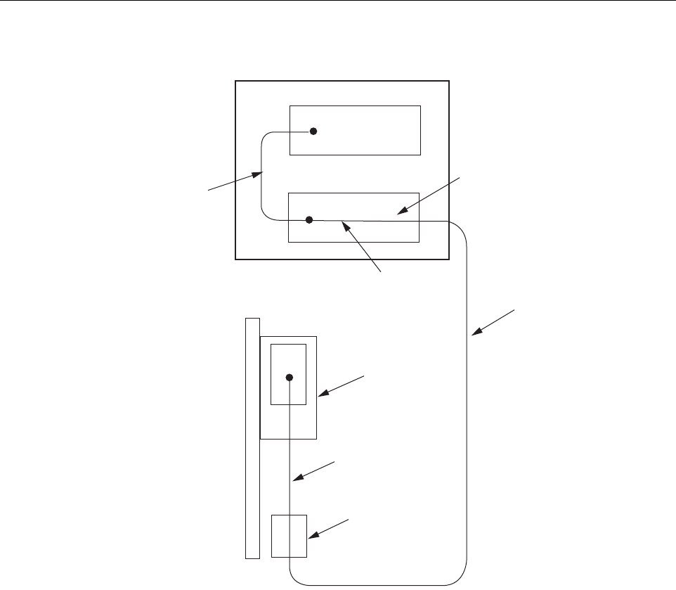
The outside plant (OSP) fiber optic cables should be routed between the HU and RU and
terminated before the equipment is installed. Adiagram of atypical OSP cable routing is shown
in Figure 3-1.At the HU, the OSP cable should be terminated at afiber distribution panel and
spliced to pigtails. Jumper patch cords may then be used to link the HU optical ports to the OSP
cable terminations. Whenever possible, aguideway such as the FiberGuide system should be
provided to protect the fiber optic patch cords from damage and to prevent excessive bending.
The procedures for connecting the OSP cable optical fibers to the HU is provided in Section 7.
ADCP-75-134 • Issue A • April 2002 • Section 3: Host Unit Installation
Page 3-3
©2002, ADC Telecommunications, Inc.
Figure 3-1. Typical OSP Cable Routing
At the RU, the OSP fiber optic cable should be spliced to aconnectorized outdoor-rated cable
(consisting of individual jacketed pigtails) which is routed into the RU cabinet. The individual
pigtails can then be connected directly to the STM optical ports. Aconnector is provided on the
bottom of the RU cabinet to seal the cable entry point and provide strain relief. The procedure
for routing the fiber cable into the RU cabinet and for connecting the pigtail leads to the STM is
provided in the Digivance LRCS Single Band SMR Remote Unit Installation Instructions
(ADCP-75-135).
When all splices and terminations are completed, test each fiber for optical loss as described in
Section 5 of this document. The optical loss budget for 9/125, single-mode, dark fiber is 17 dB
(typical). The power level of the received optical signal should not exceed –7 dBm to avoid
overdriving the optical receiver. If necessary, use an in-line optical attenuator to adjust the signal
level.
HOST UNIT
FIBER DISTRIBUTION PANEL
X
X
STM
REMOTE SITE
HOST SITE
PATCH
CORD
SPLICE
PIGTAIL
SPLICE
ENCLOSURE
INDOOR/OUTDOOR
CABLE WITH
PIGTAIL LEADS
OUTSIDE PLANT
CABLE
REMOTE UNIT
CABINET
16889-A
ADCP-75-134 • Issue A • April 2002 • Section 3: Host Unit Installation
Page 3-4
©2002, ADC Telecommunications, Inc.
3 WDM MOUNTING PROCEDURE (OPTIONAL ACCESSORY)
Abi-directional wavelength division multiplexer (WDM) is available as an accessory item for
non-diversity versions of the Digivance LRCS. If the application does not require the use of a
WDM, skip this section and proceed to Section 4.
The version of the WDM that is used with the HU consists of one or two WDM modules and a
WDM mounting shelf. Each WDM module can support two HU’s and each WDM mounting
shelf can hold two WDM modules. Afully loaded WDM mounting shelf can therefore support
four HU’s.
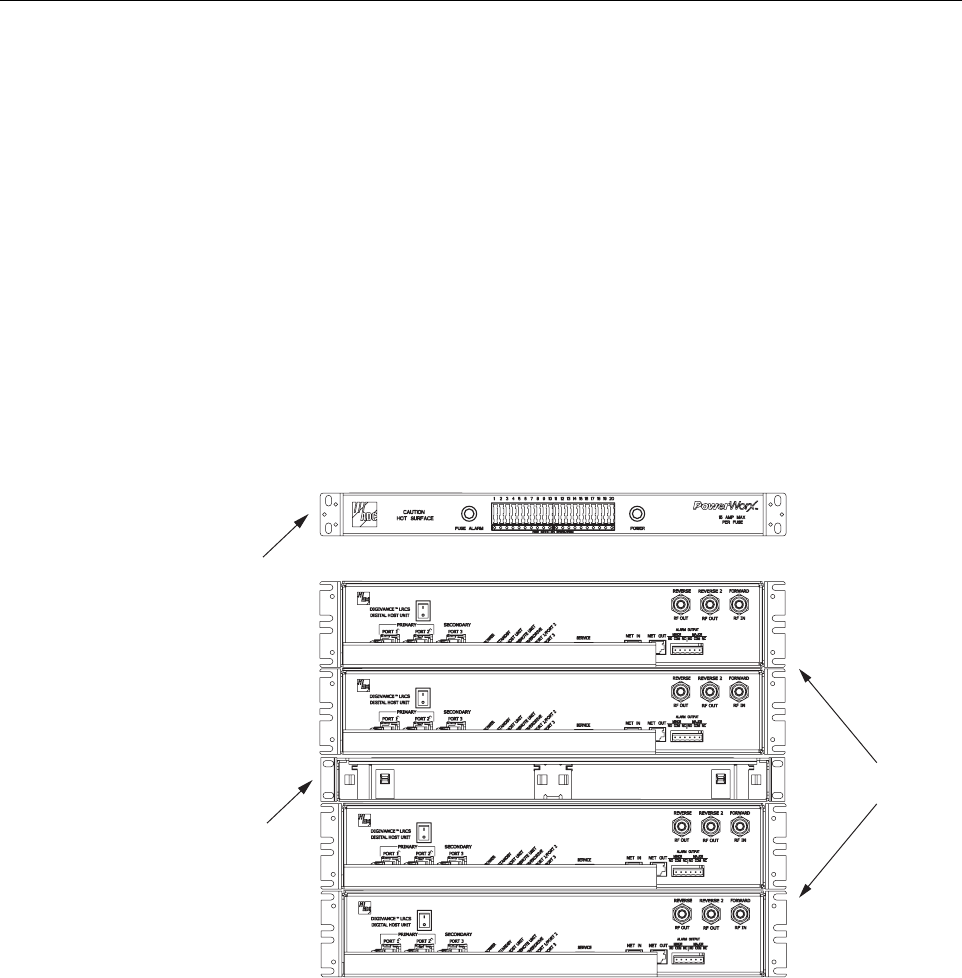
When multiple HU’s require connection to aWDM, the WDM mounting shelf and the HU’s
should be mounted in the equipment rack as shown in Figure 3-2.This configuration allows the
pigtail leads from the two WDM modules to be connected directly to the optical ports on any
one of the four HU’s.
Figure 3-2. Typical WDM and HU Configuration
The WDM mounting shelf may be mounted in either a19-inch or 23-inch EIA or WECO
equipment rack. Four #12-24 screws are provided for securing the mounting shelf to the rack.
Use the following procedure to install the WDM mounting shelf in the equipment rack and to
mount the WDM modules in the WDM mounting shelf:
1. The WDM mounting shelf is shipped with the mounting brackets installed for 19-inch EIA
rack installations. If installing the mounting shelf in a19-inch EIA rack, proceed to step 5.
If installing the mounting shelf in a19-inch WECO rack, a23-inch EIA rack, or a23-inch
WECO rack, proceed to step 2.
WDM MOUNTING
SHELF
(WITHOUT MODULES)
16886-A
POWERWORX
FUSE PANEL
HOST UNITS
ADCP-75-134 • Issue A • April 2002 • Section 3: Host Unit Installation
Page 3-5
©2002, ADC Telecommunications, Inc.
2. Remove both mounting brackets from the mounting shelf (requires Phillips screwdriver)
and save screws for reuse.
3. Locate the extra mounting brackets that are provided with the mounting shelf and select
the brackets that correspond to the rack type. Each mounting shelf includes extra brackets
for installing the mounting shelf in the rack types specified in step 1.
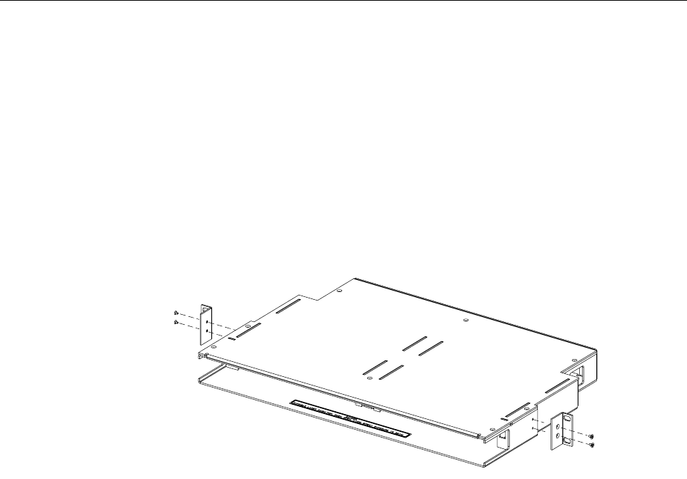
4. Install the replacement mounting brackets as shown in Figure 3-3.Use the screws
removed in step 2to attach the new brackets to the mounting shelf.
Figure 3-3. Installing the Replacement Mounting Brackets
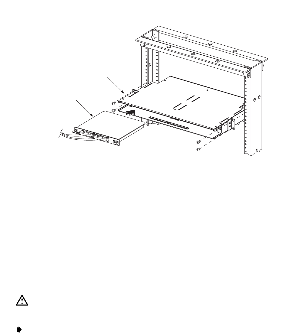
5. Position the WDM mounting shelf in the designated mounting space in the rack (per
system design plan) and then secure the mounting brackets to the rack using the four #12-
24 machine screws provided as shown in Figure 3-4.
6. Install each WDM module in the mounting shelf (see Figure 3-4). Arail on the side of the
module fits into aguide within the mounting.
7. Secure each WDM module to the mounting shelf by twisting the handle on each quarter-
turn fastener 90º.
8. Carefully store the pigtail leads from each WDM module. The routing and connection
procedures for the pigtails are provided in Section 7.
16885-A
ADCP-75-134 • Issue A • April 2002 • Section 3: Host Unit Installation
Page 3-6
©2002, ADC Telecommunications, Inc.
Figure 3-4. WDM Mounting Shelf and WDM Module Installation
4 HU MOUNTING PROCEDURE
The HU may be mounted in either a19-inch or 23-inch EIA or WECO equipment rack. Both
US standard and metric machine screws are included for rack mounting the HU. When loading
the HU in arack, make sure the mechanical loading of the rack is even to avoid ahazardous
condition such as aseverely unbalanced rack. The rack should safety support the combined
weight of all the equipment it holds. In addition, maximum recommended ambient temperature
for the HU is 50º C(122º F). Allow sufficient air circulation or space between units when the
HU is installed in amulti-rack assembly because the operating ambient temperature of the rack
environment might be greater than room ambient.
Use the following procedure to install the HU in the equipment rack:
1. The HU is shipped with the mounting brackets installed for 19-inch rack installations. If
mounting the HU in a19-inch rack, proceed to step 4. If mounting the HU in a23-inch
rack, proceed to step 2.
2. Remove both mounting brackets from the HU (requires TORX screwdriver with T20 bit)
and save screws for reuse.
Warning: Wet conditions increase the potential for receiving an electrical shock when
installing or using electrically powered equipment. To prevent electrical shock, never install or
use electrical equipment in awet location or during alightning storm.
Note: To insure that all optical connectors remain dust-free during installation, leave all dust
caps and dust protectors in place until directed to remove them for connection.
16888-A
WDM MODULE
WDM MOUNTING
SHELF
ADCP-75-134 • Issue A • April 2002 • Section 3: Host Unit Installation
Page 3-7
©2002, ADC Telecommunications, Inc.
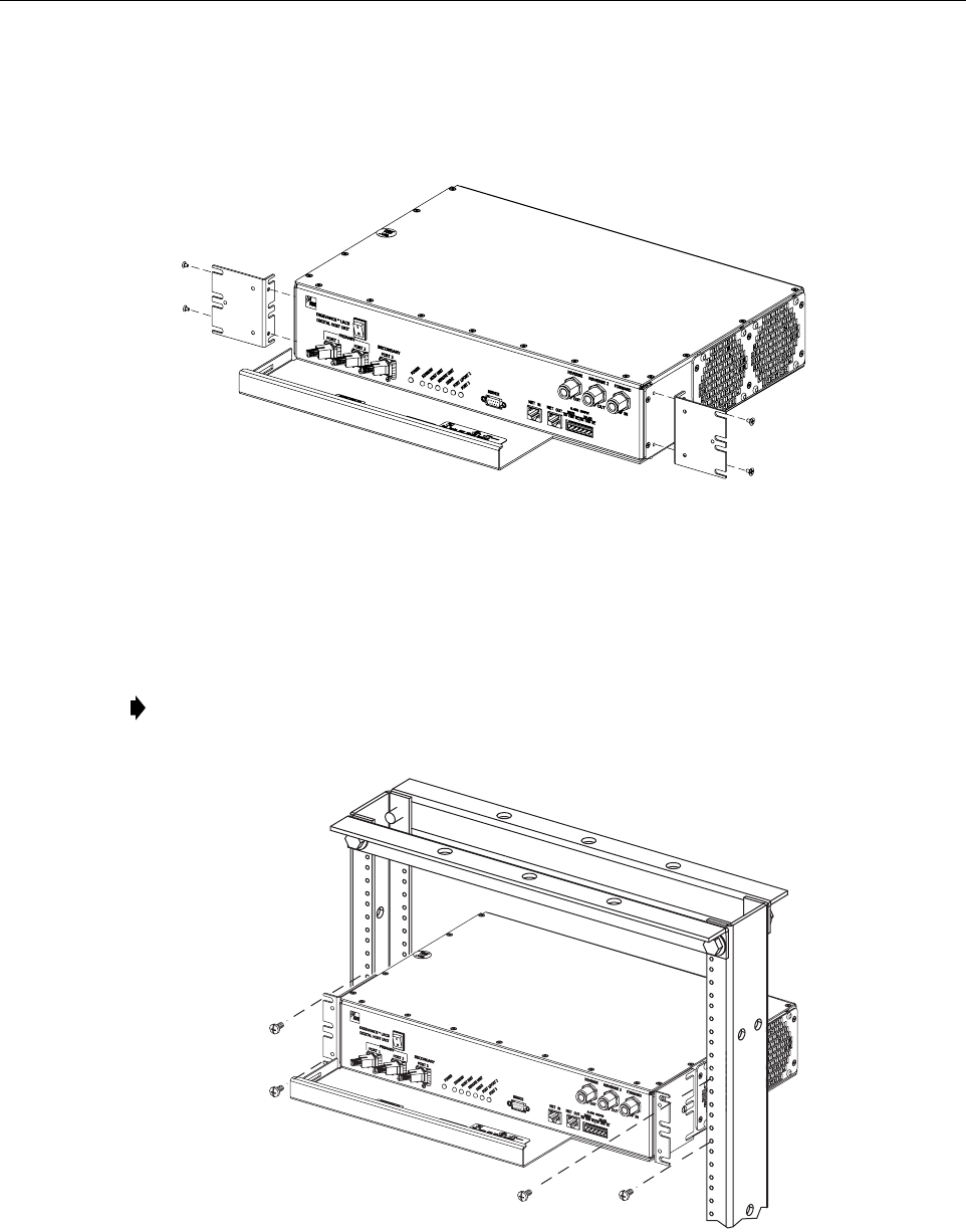
3. Reinstall both mounting brackets so the long side of the bracket is flush with the HU front
panel as shown in Figure 3-5.Use the screws removed in step 2to re-attach the brackets to
the HU chassis.
Figure 3-5. Installing the Mounting Brackets for 23-Inch Rack Installations
4. Position the HU in the designated mounting space in the rack (per system design plan) and
then secure the mounting brackets to the rack using the four machine screws provided (use
#12-24 or M6 x10 screws, whichever is appropriate) as shown in Figure 3-6.
Figure 3-6. HU Rack Mount Installation
Note: Provide aminimum of 3inches (76 mm) of clearance space on both the left and
right sides of the HU for air intake and exhaust.
16882-A
REMOVE AND REINSTALL MOUNTING
BRACKETS AS SHOWN FOR
INSTALLATION IN 23-INCH RACKS
16883-A
ADCP-75-134 • Issue A • April 2002 • Section 3: Host Unit Installation
Page 3-8
©2002, ADC Telecommunications, Inc.
5 CHASSIS GROUND CONNECTION
Astud is provided on the rear side of the chassis for connecting agrounding wire to the chassis.
Use the following procedure to connect the grounding wire to the chassis and to route the
grounding wire to an approved earth ground source.
1. Obtain alength of #18 AWG (1.00 mm) insulated stranded copper wire for use as achassis
grounding wire.
2. Terminate one end of the wire with aring terminal.
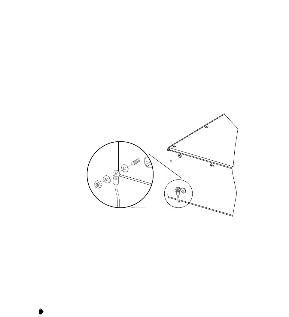
3. Locate the chassis ground stud at the rear of the HU as shown in Figure 3-7.
Figure 3-7. Chassis Ground Stud
4. Attach the ring end of the wire to the chassis ground stud (see Figure 3-7).
5. Route the free end of the chassis grounding wire to an approved (per local code or
practice) earth ground source.
6. Cut the chassis grounding wire to length and connect it to the approved ground source as
required by local code or practice.
6 COAXIAL CABLE CONNECTIONS
The RF interface between the HU and the EBTS is supported through either two (non-diversity)
or three (diversity) type Nfemale connectors mounted on the HU front panel. On non-diversity
units, one connector provides the coaxial cable connection for the forward path (downlink)
signal and the other connector provides the coaxial cable connection for the reverse path
(uplink) signal. On diversity units, athird connector provides the coaxial cable connection for
the diversity reverse path (uplink) signal.
Note: Be sure to maintain reliable grounding. Pay particular attention to ground source
connections.
16169-A
ADCP-75-134 • Issue A • April 2002 • Section 3: Host Unit Installation
Page 3-9
©2002, ADC Telecommunications, Inc.
In SMR installations, it is usually necessary to install an external attenuator in the forward path
link between the HU and the EBTS. The procedure for determining the value of the external
attenuator is provided in SECTION 4: OPERATION. The HU should be mounted as close as
possible to the EBTS to minimize cable losses. Use the following procedure to route the
forward and reverse path coaxial cables and connect them to the HU:
1. Obtain the required lengths of high performance, flexible, low loss 50-ohm coaxial
communications cable (RG-400 or equivalent) for all coaxial connections.
2. Route the forward and reverse path coaxial cables and the diversity reverse path cable (if
the HU supports diversity) between the HU and the EBTS interface (per system design
plan) and cut to the required length. Allow sufficient slack for dressing and organizing
cables at the HU and for installing an external attenuator in the forward path link.
3. Terminate each cable with atype Nmale connector following the connector supplier’s
recommendations.
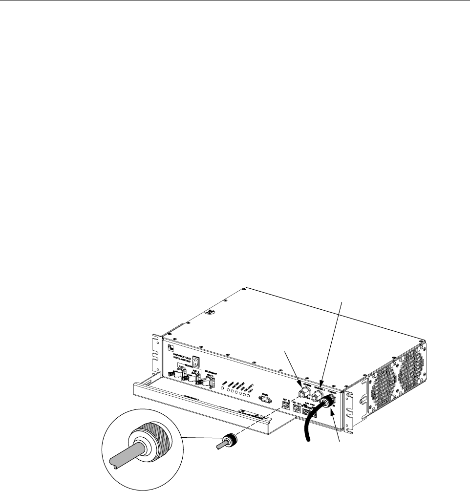
4. Connect the forward path cable to the FORWARD RF IN connector on the HU front
panel as shown in Figure 3-8.
Figure 3-8. Forward and Reverse Path Coaxial Cable Connections
5. Connect the reverse path cable to the REVERSE RF OUT connector on the HU front
panel (see Figure 3-8).
6. If the HU supports diversity, connect the diversity reverse path cable to the REVERSE 2
RF OUT connector on the HU front panel (see Figure 3-8).
7. Dress and secure cables at the HU.
8. Complete all remaining coaxial connections at the EBTS interface as specified in the
system design plan.
16887-A
TYPE-N MALE
CONNECTOR
FORWARD RF IN
CONNECTOR
(FORWARD PATH)
REVERSE
RF OUT CONNECTOR
(REVERSE PATH)
REVERSE 2
RF OUT CONNECTOR
(DIVERSITY REVERSE PATH)

ADCP-75-134 • Issue A • April 2002 • Section 3: Host Unit Installation
Page 3-10
©2002, ADC Telecommunications, Inc.
7 OPTICAL CONNECTIONS
The optical interface between the HU and the RU is supported by either two (non-diversity) or
three (diversity) optical ports. Each optical port consists of an SC optical adapter which is
mounted on the HU front panel. Port 1provides the optical fiber connection for the forward path
(downlink) signal. Port 2provides the optical fiber connection for the reverse path (uplink)
signal. Port 3provides the optical fiber connection for the diversity reverse path (uplink) signal.
The optical connections are dependent on whether or not aWDM (optional accessory) is
installed. If the installation does not include aWDM, proceed to Section 6.1 for the optical
connections procedure. If the installation does include aWDM, proceed to Section 6.2 for the
optical connections procedure.
7.1 Optical Connections Without WDM
Use the following procedure to connect the optical fibers when aWDM is not installed with the
HU:
1. Obtain two (non-diversity) or three (diversity) patch cords that are of sufficient length to
reach from the HU to the fiber distribution panel.
2. Designate one of the patch cords as the forward path link and the other as the reverse
path link and attach an identification label or tag next to the connector. For diversity
systems, designate and label or tag athird patch cord as the diversity reverse path link.
3. Remove the dust caps from the HU optical ports and from the patch cord connectors that
will be connected to the HU.
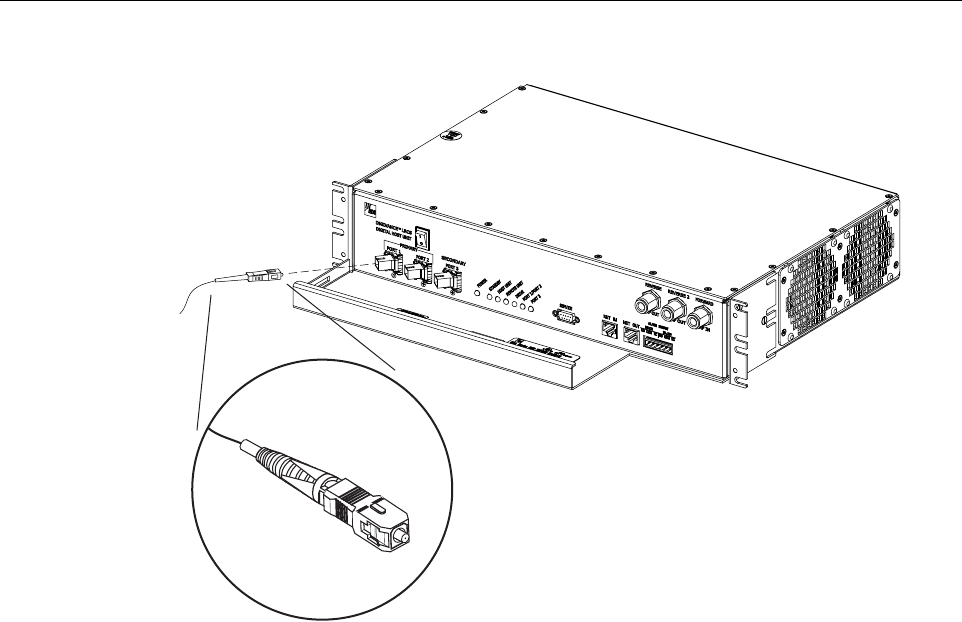
4. Clean each patch cord connector (follow connector supplier’s recommendations) and then
insert the connector into the appropriate optical port as shown in Figure 3-9 and as
specified by the following:
Port 1 - Forward path patch cord
Port 2 - Reverse path patch cord
Port 3 - Diversity reverse path patch cord
5. Route the patch cords from the HU to the fiber distribution panel.
Danger: This equipment uses aClass 1Laser according to FDA/CDRH rules. Laser radiation
can seriously damage the retina of the eye. Do not look into the ends of any optical fiber. Do not
look directly into the optical transmitter of any unit or exposure to laser radiation may result.
An optical power meter should be used to verify active fibers. Aprotective cap or hood MUST
be immediately placed over any radiating transmitter or optical fiber connector to avoid the
potential of dangerous amounts of radiation exposure. This practice also prevents dirt particles
from entering the connector.
Note: The HU optical adapters are angled to the left.Therefore, patch cords should always
be routed to the HU from the left side of the rack. Routing patch cords to the HU from the
right side of the rack may exceed the bend radius limitations for the optical fiber.
ADCP-75-134 • Issue A • April 2002 • Section 3: Host Unit Installation
Page 3-11
©2002, ADC Telecommunications, Inc.
Figure 3-9. Fiber Optic Cable Connections To Host Unit
6. Identify the OSP cable optical fiber terminations that correspond to the RU.
7. Designate one of the OSP fibers as the forward path link and the other as the reverse
path link and attach an identification label or tag next to the connector. For diversity
systems, designate and label or tag athird fiber as the diversity reverse path link.
8. Remove the dust caps from the OSP cable optical fiber adapters and from the patch cord connectors.
9. Clean each patch cord connector (follow connector supplier’s recommendations) and then
mate the connector with the appropriate OSP cable adapter.
10. Store any excess patch cord slack at the fiber distribution panel.
7.2 Optical Connections With WDM
Use the following procedure to connect the optical fibers when aWDM module is installed with
the HU:
1. Obtain apatch cord that is of sufficient length to reach from the WDM module to the fiber
distribution panel.
2. Remove the dust cap from one of the two optical ports on the WDM module and from the
patch cord connector that will be connected to the WDM module.
16893-A
ADCP-75-134 • Issue A • April 2002 • Section 3: Host Unit Installation
Page 3-12
©2002, ADC Telecommunications, Inc.
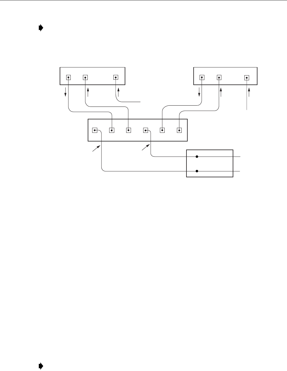
Figure 3-10. Fiber Optic Connections To WDM Module
3. Clean the patch cord connector (follow connector supplier’s recommendations) and then
insert the connector into one of the WDM module’s optical ports (port 1or 4).
4. Route the patch cord from the WDM to the fiber distribution panel.
5. Identify the OSP cable optical fiber termination that corresponds to the RU.
6. Remove the dust cap from the OSP cable optical adapter and from the patch cord
connector.
7. Clean the patch cord connector (follow connector supplier’s recommendations) and then
mate the connector with the appropriate OSP cable adapter.
8. Store any excess patch cord slack at the fiber distribution panel.
9. Remove the dust caps from the HU optical ports and from the WDM pigtails that will be
connected to the HU.
10. Clean each pigtail connector (follow connector supplier’s recommendations) and then
insert the connector into the appropriate optical port on the HU as shown in Figure 3-9 and
as diagramed in Figure 3-10.
Note: Each WDM module can support two separate HU’s. The WDM module ports are
numbered from 1through 6as shown in Figure 3-10.Ports 1through 3are used for HU #1
and Ports 4through 6are used for HU #2.
Note: The HU optical adapters are angled to the left.Therefore, pigtails should always be
routed to the HU from the left side of the rack. Routing pigtails to the HU from the right
side of the rack may exceed the bend radius limitations for the optical fiber.
PORT 1 PORT 2
HOST UNIT 1 HOST UNIT 2
PORT 1 PORT 2
PORT 3
PORT 3
16892-B
REVERSE
PATH
REVERSE
PATH
FORWARD
PATH
FORWARD
PATH
WAVELENGTH DIVISION
MULTIPLEXER
OSP CABLE
OPTICAL FIBERS
HOST UNIT 1
(BI-DIRECTIONAL FIBER
LINK WITH REMOTE UNIT)
HOST UNIT 2
(BI-DIRECTIONAL FIBER
LINK WITH REMOTE UNIT)
FIBER DISTRIBUTION
PANEL (FDP)
X
X
123 45 6
DIVERSITY
REVERSE PATH
DIVERSITY
REVERSE PATH
TO FDP
TO FDP