ADC Telecommunications DVLRCSSMR Digivance Long Range Coverage Solution SMR System User Manual 75134
ADC Telecommunications Inc Digivance Long Range Coverage Solution SMR System 75134
Contents
Part 4 new manual
ADCP-75-134 • Issue A • April 2002 • Section 3: Host Unit Installation
Page 3-13
©2002, ADC Telecommunications, Inc.
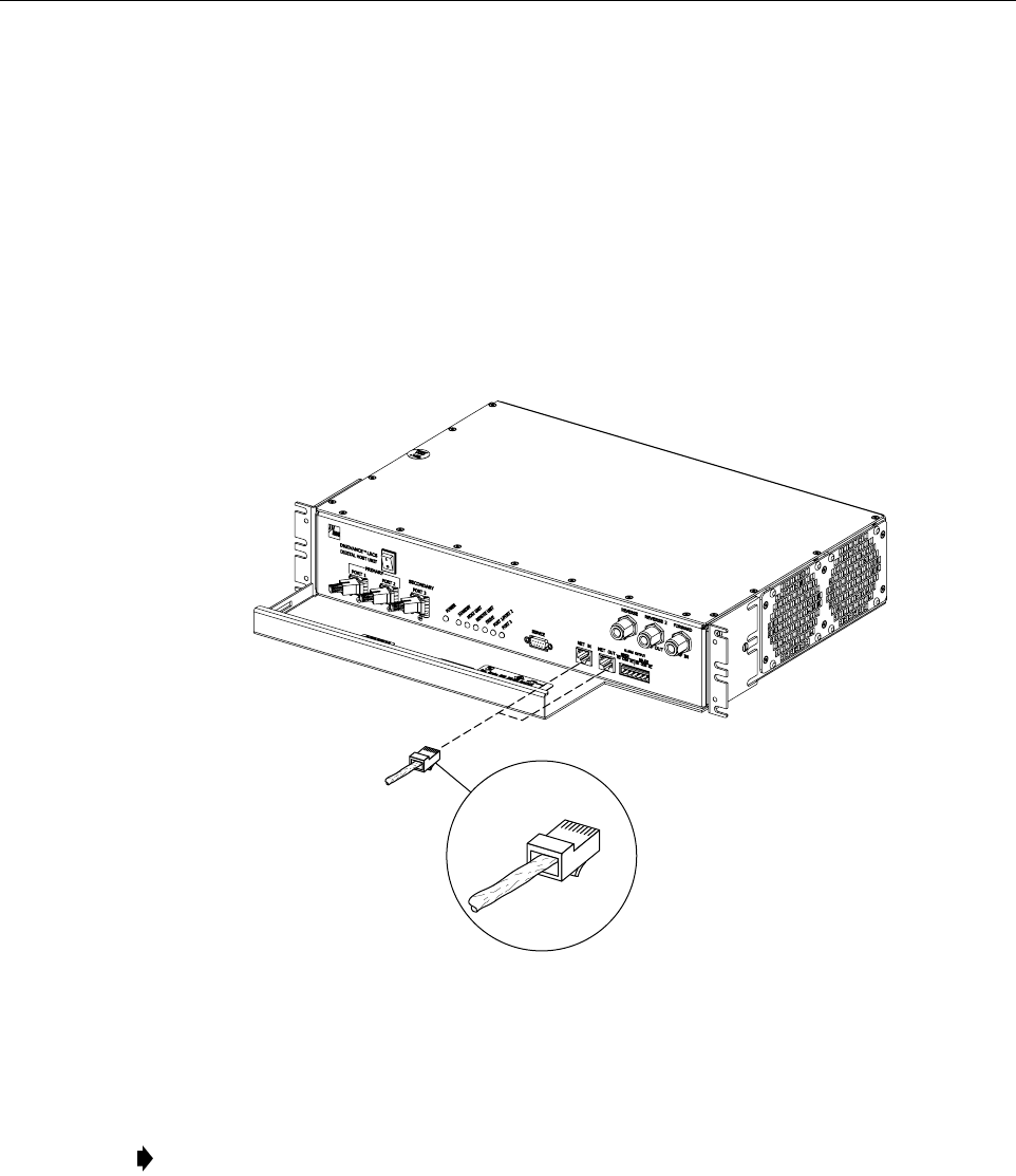
8 CONTROLLER AREA NETWORK CONNECTIONS
Controller area Network (CAN) interface connections between multiple HU’s are supported by
apair of RJ-45 jacks. One of the jacks is designated as the NET IN port and the other jack is
designated as the NET OUT port. The CAN interface allows up to 15 HU’s to be connected
together (in daisy-chain fashion) and controlled through asingle Digivance EMS computer. A
one meter long cable is provided with each HU for CAN connections. Use the following
procedure to connect CAN interface cables between multiple HU’s:
1. Connect one end of the CAN interface cable (provided with the HU) to either the NET IN
or NET OUT port on HU #1 as shown in Figure 3-11.
Figure 3-11. Controller Area Network Connections
2. Route the CAN interface cable to HU #2 and connect the cable’s free end to the port that is
the logical opposite of the network port the cable was connected to at HU #1.
3. If athird HU will be connected to the network, connect asecond CAN interface cable to
the remaining network port on HU #2.
4. Route the second CAN interface cable to HU #3 and connect the cable’s free end to the
port that is the logical opposite of the port that the cable is connected to at HU #2.
5. Repeat steps 3and 4for each additional HU that is added to the network up to atotal of 15
HU’s. Adiagram of typical CAN interface connections is shown in Figure 3-12.
Note: If connected to aNET OUT port at HU #1, connect to the NET IN port at HU #2. If
connected to aNET IN port at HU #1, connect to aNet OUT port at HU #2.
16901-A
RJ-45 CONNECTOR
DETAIL
FCC ID: F8I-DVLRCSSMR Class II Permissive Change
Manual - Part 4
ADCP-75-134 • Issue A • April 2002 • Section 3: Host Unit Installation
Page 3-14
©2002, ADC Telecommunications, Inc.
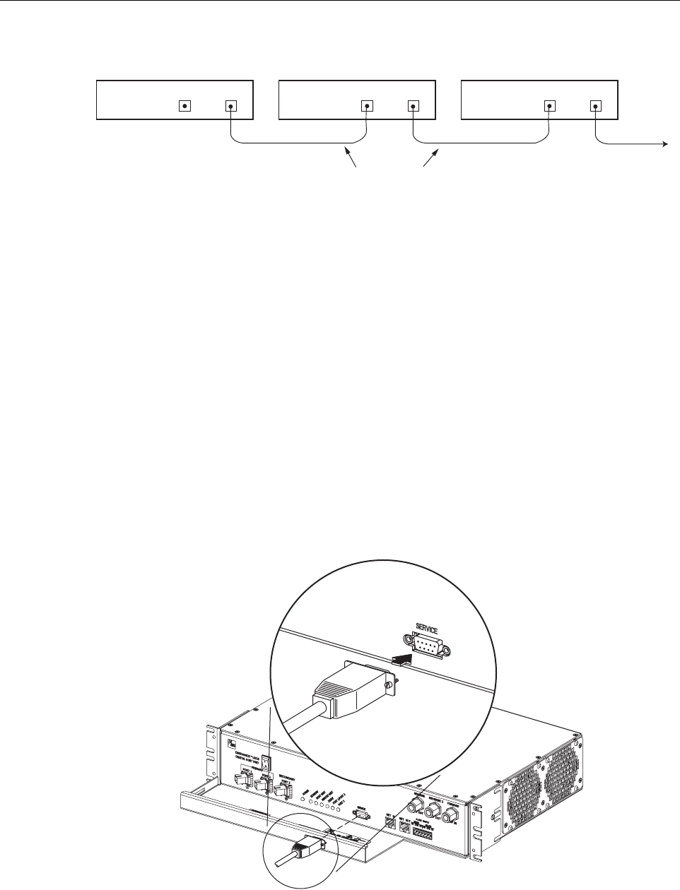
Figure 3-12. Configuring CAN Connections with Multiple Host Units
9 SERVICE INTERFACE CONNECTION
The service interface connection between the HU and the Digivance EMS computer is
supported by asingle DB-9 female connector. The service connector provides an RS-232 DTE
interface. Athree meter long straight-through RS-232 interface cable is provided with the HU
for connecting the EMS computer to the HU. Use the following procedure to install the service
interface cable:
1. Connect one end of the service interface cable (provided with HU) to the SERVICE port as
shown in Figure 3-13.
2. Route the service interface cable to the EMS computer and connect the free end of the
cable to the computer’s RS-232 DCE port. Refer to the user manual provided with the
computer to locate the required port.
Figure 3-13. Service Interface Connection
HOST UNIT 1 HOST UNIT 2 HOST UNIT 3
NET IN NET OUT NET IN NET OUT NET IN NET OUT
16900-A
CONTROLLER AREA NETWORK
INTERFACE CABLES
TO NEXT HOST UNIT
16890-A

ADCP-75-134 • Issue A • April 2002 • Section 3: Host Unit Installation
Page 3-15
©2002, ADC Telecommunications, Inc.
10 EXTERNAL ALARM SYSTEM CONNECTIONS
The alarm interface between the HU and an external alarm system is supported by asix-terminal
plug (with screw-type terminals) that connects to areceptacle mounted on the HU front panel.
The terminal plug provides connections to normally open (NO) and normally closed (NC) dry
type alarm contacts for both major and minor alarms. Acategory 3or 5cable is typically used to
connect the HU to the external alarm system. Use the following procedure to install the alarm
wiring and connect it to the HU:
1. Obtain the required length of category 3or 5cable.
2. Route the cable between the HU and the external alarm system (if not already routed) and
then cut to the required length. Allow sufficient slack for dressing and organizing the cable
at the HU.
3. Strip back the outer cable sheath and insulation to expose the wires at both ends of the
cable and strip back 0.2 inches (5 mm) of insulation from each wire.
4. Connect the Major alarm wire pair to the MAJOR COM/NC or MAJOR COM/NO
terminals (whichever is required by the external alarm system) on the HU alarm terminal
connector (supplied with HU) as shown in Figure 3-14.
Figure 3-14. External Alarm System Connections
5. Connect the Minor alarm wire pair to the MINOR COM/NC or MINOR COM/NO
terminals (whichever is required by the external alarm system) on the HU alarm terminal
connector (see Figure 3-14).
16884-A
ALARM
CONNECTOR
MAJOR
ALARM
WIRES
MINOR
ALARM
WIRES
ALARM CONNECTOR
DETAIL
ADCP-75-134 • Issue A • April 2002 • Section 3: Host Unit Installation
Page 3-16
©2002, ADC Telecommunications, Inc.
6. Connect the Major and Minor alarm wire pairs to the appropriate terminals on the external
alarm system.
7. Dress and secure cable per standard industry practice.
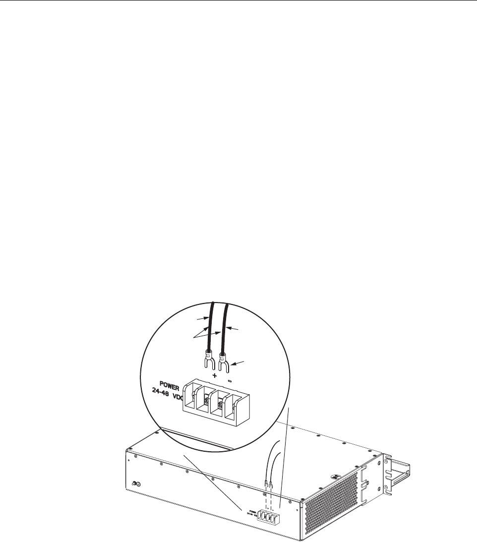
11 DC POWER CONNECTIONS
The HU is powered by ±24 or ±48 Vdc power. The power is fed to the HU through ascrew-
down type terminal strip located on the rear side of the unit. Power to the HU must be supplied
through afuse panel such as the 20 position PowerWorx fuse panel (available separately) and
the power must be protected with a 3 Amp GMT fuse. Use the following procedure to install the
power wiring:
1. Obtain one pair of #18 AWG (1.00 mm) red and black insulated copper wire for use as the
power wiring.
2. Terminate one end of each wire with afork terminal as shown in Figure 3-15.
3. Connect the power wires to the power terminal strip at the rear of the HU.
Figure 3-15. DC Power Connections
4. Route the free ends of the wires to the fuse panel and locate the terminals that will be used
for the power feed. Refer to the user manual provided with the fuse panel for specific
information.
5. Remove the fuse from the circuit that will power the HU.
FORK
TERMINALS
#18 AWG
(1.0mm)
COPPER
WIRE
+ (RED)
– (BLACK)
16891-A

ADCP-75-134 • Issue A • April 2002 • Section 3: Host Unit Installation
Page 3-17
©2002, ADC Telecommunications, Inc.
6. Connect the power wires to the appropriate terminals as specified in the fuse panel user
manual.
7. Dress and secure the power wiring at the fuse panel and the HU. The procedure for
checking the voltage level and verifying that the HU is ready to power up is provided in
SECTION 4: OPERATION.

ADCP-75-134 • Issue A • April 2002 • Section 3: Host Unit Installation
Page 3-18
©2002, ADC Telecommunications, Inc.
Blank

ADCP-75-134 • Issue A • April 2002 • Section 4: Operation
Page 4-1
©2002, ADC Telecommunications, Inc.
SECTION 4: OPERATION
1 BEFORE STARTING OPERATION . . . . . . . . . . . . . . . . . . . . . . . . . . . . . . . . . . . . . . . . . . . . . . . . . . . . . . . . . . . .4-1
1.1 Tools and Materials . . . . . . . . . . . . . . . . . . . . . . . . . . . . . . . . . . . . . . . . . . . . . . . . . . . . . . . . . . . . . . .4-1
1.2 Readiness Check . . . . . . . . . . . . . . . . . . . . . . . . . . . . . . . . . . . . . . . . . . . . . . . . . . . . . . . . . . . . . . . . .4-2
2 TURN-UP SYSTEM AND VERIFY OPERATION . . . . . . . . . . . . . . . . . . . . . . . . . . . . . . . . . . . . . . . . . . . . . . . . . . . .4-2
2.1 Turn-Up Procedure. . . . . . . . . . . . . . . . . . . . . . . . . . . . . . . . . . . . . . . . . . . . . . . . . . . . . . . . . . . . . . . .4-3
2.2 Download HU and RU System Software . . . . . . . . . . . . . . . . . . . . . . . . . . . . . . . . . . . . . . . . . . . . . . . . .4-6
2.3 Determine Baseline Forward Path Input Signal Level . . . . . . . . . . . . . . . . . . . . . . . . . . . . . . . . . . . . . . . .4-7
2.4 Enter Site Number and Site Name . . . . . . . . . . . . . . . . . . . . . . . . . . . . . . . . . . . . . . . . . . . . . . . . . . . . .4-9
2.5 Enter Host Forward Attenuation . . . . . . . . . . . . . . . . . . . . . . . . . . . . . . . . . . . . . . . . . . . . . . . . . . . . . . 4-10
2.6 Determine Output Signal Level at DDS Antenna Ports . . . . . . . . . . . . . . . . . . . . . . . . . . . . . . . . . . . . . . . 4-12
2.7 Enter Remote Forward Attenuation. . . . . . . . . . . . . . . . . . . . . . . . . . . . . . . . . . . . . . . . . . . . . . . . . . . . 4-12
2.8 Enter Host Reverse Attenuation . . . . . . . . . . . . . . . . . . . . . . . . . . . . . . . . . . . . . . . . . . . . . . . . . . . . . . 4-14
2.9 Enter Host Forward and Reverse Delay . . . . . . . . . . . . . . . . . . . . . . . . . . . . . . . . . . . . . . . . . . . . . . . . . 4-16
_________________________________________________________________________________________________________
1 BEFORE STARTING OPERATION
This section provides guidelines for turning-up the Digivance LRCS, verifying that all units are
operating properly, testing to ensure that all performance requirements are satisfied, and
correcting any installation problems. This process assumes that the various units have been
installed in accordance with the system design plan.
1.1 Tools and Materials
The following tools and materials are required in order to complete the procedures in this
section:
• Portable spectrum analyzer or RF power meter
•AC/DCvoltmeter
• External attenuators (if specified in system design plan)
• PC-type computer with Digivance Element Management System (EMS) software installed
• Straight-through RS-232 DB-9 interface cable (ADC part #1192835)
• Handset
• Pencil or pen
• Writing pad
Content Page

ADCP-75-134 • Issue A • April 2002 • Section 4: Operation
Page 4-2
©2002, ADC Telecommunications, Inc.
1.2 Readiness Check
Before starting the turn-up process, inspect the complete LRCS system to verify that all
components of the system are ready to be powered-up. This will ensure that no units of the
system will be damaged during turn-up and that all existing systems will continue to function
properly.
1.2.1 Host Unit Installation Checks
Complete the following checks at the HU prior to starting the turn-up process:
1. Verify that the ON/OFF switch on the HU is in the OFF position (press O).
2. At the fuse panel, install a 3 Amp GMT fuse in the circuit that supplies DC power to the HU.
3. Using aDC voltmeter, verify that the DC voltage level at the HU power terminals is
between ±24 or ±48 Vdc (can be either polarity).
4. Verify that all electrical and optical connections have been completed and that all optical
fibers, coaxial cables, and wires are properly routed and secured.
1.2.2 Remote Unit Installation Checks
Complete the following checks at the RU prior to starting the turn-up process:
1. Verify that the ON/OFF switch on the STM is in the OFF position (press O).
2. Verify that the RF ON/OF switch on the LPA in the OFF position.
3. At the AC breaker box, close the circuit breaker for the circuit that supplies AC power to
the RU.
4. Using an AC voltmeter, verify that the AC voltage level at the AC outlet is between 110
and 120 Vac (for 120 Vac powered systems) or between 220 and 240 Vac (for 240 Vac
powered systems).
5. Verify that all electrical and optical connections have been completed and that all optical
fibers, coaxial cables, and wires are properly routed and secured.
2 TURN-UP SYSTEM AND VERIFY OPERATION
The process of turning-up the system and verifying operation involves powering up the various
system components, verifying that the LED indicators show normal operation, setting the site
number and name, adjusting the RF signal levels, and adjusting the path delay.

ADCP-75-134 • Issue A • April 2002 • Section 4: Operation
Page 4-3
©2002, ADC Telecommunications, Inc.
2.1 Turn-Up Procedure
Use the following procedure to turn-up the system:
1. Temporarily disconnect the external alarm system or notify the alarm system provider that
testing is in progress.
2. If turning-up multiple HU and RU systems that have not been configured for operation
before, temporarily disconnect the CAN cables from the NET IN and NET OUT ports of
each HU.
3. Determine if the forward path input signal level at the Host Unit FORWARD RF IN port is
between –20 and –40 dBm and adjust level if required. Refer to Section 2.3 for the
calculation and adjustment procedure.
4. Connect the EMS computer (if not already connected) to the SERVICE connector on the
HU or STM front panel. If necessary, aseparate laptop computer loaded with the EMS
software can be temporarily connected and used to initially configure the system.
5. Place the ON/OFF switch on the HU in the ON position (press I).
6. Place the ON/OFF switch on the STM in the ON position (press I).
7. Wait 6to 8seconds for the HU and the RU modules to initialize and then observe the LED
indicators on the HU, STM and LPA. Refer to Section 5 for the troubleshooting
procedures if the indicators do not respond as specified.
8. Start up the Digivance EMS software program. The EMS main window will open as
shown in Figure 4-1.Note: The EMS software should be installed on aPC-type computer
and the PC’s COM port should be configured to interface with the HU. For information
about installing the EMS software and configuring the PC’s COM port, refer to the
Digivance Element Management System Software User Manual (ADCP-75-118).
Note: By default, all HU’s and RU’s are programmed with the same site number and
name. This can cause problems for the Digivance EMS if multiple HU’s with the same site
number and site name are networked together through the CAN interface. It is therefore
advisable to temporarily disconnect the CAN interface cables from the HU until aunique
site number and name can be entered for each HU and its corresponding RU.
HOST UNIT SPECTRUM TRANSPORT MODULE LINEAR POWER AMPLIFIER
POWER –Green AC POWER –Green FAIL –Off
STANDBY –Off STANDBY –Off SHUTDOWN –Red
HOST UNIT –Green HOST UNIT –Green Digital Display –FORCED
SHUTDOWN
REMOTE UNIT –Green STM –Green
DRIVE –Green, Yellow, or Red PA –Green
PORT 1/PORT 2 – Green VSWR –Green
PORT 3 – Green
(diversity unit only) PORT 1/PORT 2 – Green
PORT 3 – Green
(diversity unit only)

ADCP-75-134 • Issue A • April 2002 • Section 4: Operation
Page 4-4
©2002, ADC Telecommunications, Inc.
Figure 4-1. Digivance Element Management System Main Window
9. Open the View drop down menu and connect to the Host and Remote pair by selecting
“NotNamed/NotNamed”. The HOST Alarms display and the REMOTE Alarms display
will open within the main window as shown in Figure 4-2.
10. Download the system software to both the Host and the Remote unit. Refer to Section 2.2
for details.
Figure 4-2. Selecting Display Tabs
Click to view drop
down menu
Clicking on the tabs in
this list will open the cor-
responding display.
Host/Remote pair
site name

ADCP-75-134 • Issue A • April 2002 • Section 4: Operation
Page 4-5
©2002, ADC Telecommunications, Inc.
11. Click on the HOST Config tab and on the REMOTE Config tab (see Figure 4-2). The
HOST Config display and the REMOTE Config display will open within the main
window.
12. Enter the Site Number and Site Name for both the HOST and the REMOTE unit. Refer to
Section 2.4 for details.
13. Reconnect the CAN cables to the HU’s NET IN and NET OUT ports.
14. Verify that no Major (except Major Extern Alarm) or Minor alarms are being reported in
either the HOST or REMOTE Alarm displays and that all alarm fields (except Major
Extern Alarm) are green.
15. Click on the HOST RF tab (see Figure 4-2). The HOST RF display will open within the
main window.
16. Enter the Host Fwd Att (Forward Attenuation) values. This sets the forward input RF signal
level at the HU. Refer to Section 2.5 for details. By default, this value is set to 0dB. If the
DRIVE LED on the HU front panel was red, it should turn green when this step is completed.
17. Determine if the RF output power at each DDS ANTENNA port is at the correct level per
channel up to amaximum of 12 watts. Refer to Section 2.6 for details.
18. Click on the REMOTE LPA tab (see Figure 4-2). The REMOTE PA display will open
within the main window.
19. Enter the Remote Fwd Att value. This adjusts the RF output signal level at the STM
ANTENNA port. Refer to Section 2.7 for details. By default this value is set to 0dB.
20. Place the RF ON/OFF switch (on LPA front panel) in the ON position.
21. Verify that the SHUTDOWN LED indicator (on LPA front panel) turns from red to off and
the Digital Display message changes from FORCED SHUTDOWN to NORMAL
OPERATION.
22. Click on the HOST RF tab (see Figure 4-2). The HOST RF display will open within the
main window.
23. Enter the Host Rev Att (Reverse Attenuation), and Host Div Rev Att (Diversity Reverse
Attenuation) values. This sets the reverse output RF signal levels at the HU. Refer to
Section 2.8 for details.
24. If adelay adjustment is required per the system design plan, enter the Host Fwd Delay,
Host Rev Delay,and Host Div Rev Delay values. By default, the delay values are set to 0.
Refer to Section 2.9 for details.
25. If aseparate laptop computer loaded with the EMS software was used to initially
configure the system, disconnect the laptop computer from the SERVICE connector on the
HU front panel.
Note: Each HU and RU pair will generally remain permanently connected to aPC-type
desktop computer loaded with the EMS software. When two or more systems are
connected together through the CAN interface, only one EMS computer is required to
manage the networked HU and RU systems. The EMS computer may be connected to the
SERVICE power on any one of the HUs in the network.
ADCP-75-134 • Issue A • April 2002 • Section 4: Operation
Page 4-6
©2002, ADC Telecommunications, Inc.
26. Reconnect the external alarm system or notify the alarm system provider that the turn-up
process has been completed.
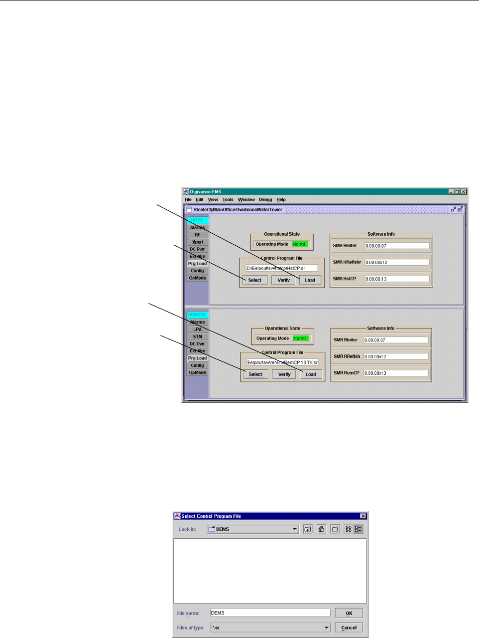
2.2 Download HU and RU System Software
The HU’s and RU’s may require asystem software download to make them operational. Use the
following procedure to download the system software:
1. Click on the HOST Prg Load tab and on the REMOTE Prg Load tab. The HOST Prg
Load display and the Remote Prg Load display will open within the EMS main window
as shown in Figure 4-3.
Figure 4-3. HOST and REMOTE Prg Load Displays
2. Click on the HOST Select button (see Figure 4-3). The Select Control Program File
window will open as shown in Figure 4-4.Browse until the folder where the Control
Program files are located is selected and the software files are displayed in the window.
Figure 4-4. Select Control Program File Window
Click to open Select Control
Program window for HOST
Click to start down-
load to HOST.
Click to start down-
load to REMOTE.
Click to open Select
Control Program win-
dow for REMOTE.

ADCP-75-134 • Issue A • April 2002 • Section 4: Operation
Page 4-7
©2002, ADC Telecommunications, Inc.
3. Select the required file to download and click on the OK button.
4. Click on the HOST Load button (see Figure 4-3)to start the download.
5. Repeat steps 2through 4for the REMOTE.
2.3 Determine Baseline Forward Path Input Signal Level
The level of the composite RF output signal at the FORWARD RF IN port at the HU will vary
depending on the type of BTS, the cable loss, and the number of channels present. To interface
with the HU, the signal level of the composite forward path RF signal must be adjusted to fall
within arange of –20 to –40 dBm.If the signal level is not within this range, it must be adjusted
to fall within this level through the use of an external attenuator. Use the following procedure to
measure and adjust the input RF signal level at the HU:
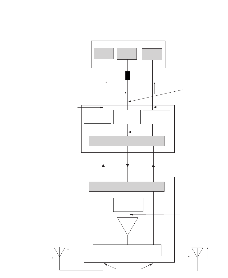
1. Connect aspectrum analyzer or power meter to the forward path output port at the EBTS.
The required signal levels and test points are shown in Figure 4-5.
2. Measure the RF level of asingle carrier, such as the control channel, in dBm. Make sure
the resolution bandwidth of the spectrum analyzer or power meter is narrow enough to
measure the power of the single 30 kHz channel only.
3. Verify that all carriers are coming in at equal power at bandwidth and adjust to the same
level if necessary.
4. Calculate the total composite signal power from the EBTS using the following formula:
Ptot = Pc+10Log N
Where,
Ptot is the total composite power in dBm
Pcis the power per carrier in dBm as measured in step 2, and
Nis the total number of channels.
5. Determine the total cable loss that is imposed by the forward path coaxial cable that links
the EBTS to the HU and also any insertion loss imposed by splitters or combiners.
6. Subtract the total cable loss and any insertion losses from the total composite power
calculated in step 4.
7. Subtract –30 (the midpoint of the required range) from the value determined in step 6. The
difference (which should be positive) equals the value of the external attenuator that is
required to reduce the forward path signal level to fall within the required range. The
following formula outlines the required calculations for steps 6and 7:
Ptot – (Cable and insertion loss) –(–30) =Value of external attenuator required
Note: If the input signal level is already within the required range of –20 to –40 dBm, then
no external attenuator is required.
ADCP-75-134 • Issue A • April 2002 • Section 4: Operation
Page 4-8
©2002, ADC Telecommunications, Inc.
Figure 4-5. Signal Levels, Test Points, and Adjustments
INPUT SIGNAL LEVEL
(-20 to -40 dBm
COMPOSITE)
HOST UNIT
ANTENNA 2
REMOTE UNIT
EXTENDED BASE
TRANSCEIVER STATION
17616-A
PRIMARY
RECEIVER
0 to 20 dB
ATTENUATOR
(HOST REV ATT)
0 to 20 dB
ATTENUATOR
(HOST DIV ATT)
OPTICAL LINK
ANTENNA 1
DUAL DUPLEXER/SPLITTER
ADJUSTMENTS TO INPUT
SIGNAL LEVEL AS SET BY HOST
FORWARD PATH ATTENUATOR
ADJUSTMENTS TO OUTPUT
SIGNAL LEVEL AS SET BY HOST
REVERSE PATH ATTENUATOR
ADJUSTMENTS TO OUTPUT
SIGNAL LEVEL AS SET BY HOST
DIVERSITY PATH ATTENUATOR
MAXIMUM OUTPUT SIGNAL
LEVEL AT DDS ANTENNA PORTS
ADJUSTMENTS TO
OUTPUT SIGNAL LEVEL
AS SET BY THE REMOTE
FORWARD ATTENUATOR
LPA
EXTERNAL
ATTENUATOR
TRANS-
MITTER
0 to 20 dB
ATTENUATOR
(HOST FWD ATT)
0 to 20 dB
ATTENUATOR
(REMOTE FWD ATT)
DIVERSITY
RECEIVER
RF, OPTICS,
AND CONTROL
RF, OPTICS,
AND CONTROL