ADC Telecommunications DVLRCSSMR Digivance Long Range Coverage Solution SMR System User Manual 75134
ADC Telecommunications Inc Digivance Long Range Coverage Solution SMR System 75134
Contents
Part 5 new manual
ADCP-75-134 • Issue A • April 2002 • Section 4: Operation
Page 4-9
©2002, ADC Telecommunications, Inc.
8. Select an attenuator that is as close to the value calculated in step 7as possible. Select a
value that will adjust the signal level of the composite input signal to fall within the
specified range.
9. Install the external attenuator in the coaxial cable that is connected to the FORWARD RF
IN port at the HU.
10. Subtract the value of the external attenuator used in step 9from the total composite signal
power (Ptot)and record the result. This value will be required when setting the attenuation
of the HU’s internal forward attenuator.
2.4 Enter Site Number and Site Name
All HU’s and RU’s are programmed with the same site number and site name. It is therefore
necessary to assign aunique site name and site number to the HU and RU before they can be
connected to the same CAN. Use the following procedure to assign aunique site number and
name to each HU and RU system:
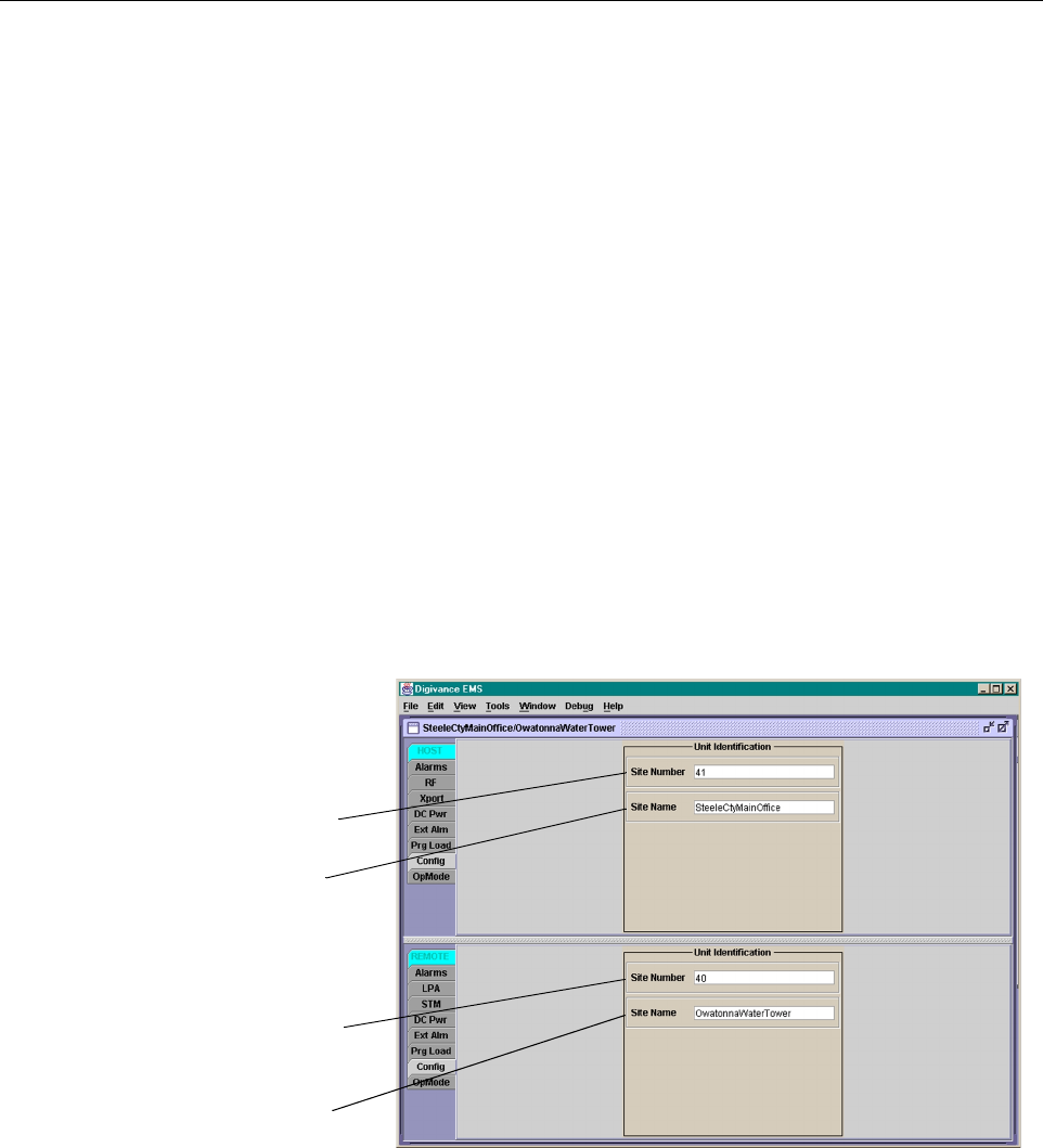
1. Click on the HOST Config tab and on the REMOTE Config tab. The HOST Config
display and the REMOTE Config display will open within the EMS main window as
shown in Figure 4-6.
Figure 4-6. HOST and REMOTE Config Displays
2. Right-click on the HOST Site Number (see Figure 4-6). The Site Number pop-up screen
will open as shown in Figure 4-4. Enter any odd number between 33 and 61 and then click
on OK to close the screen and make the changes take effect.
HOST Site Number
HOST Site Name
REMOTE Site Number
(Entered automatically
when the HOST site
number is selected)
REMOTE Site Name
Right-Click on the
point shown to open
pop-up screen
FCC ID: F8I-DVLRCSSMR Class II Permissive Change
Manual - Part 5

ADCP-75-134 • Issue A • April 2002 • Section 4: Operation
Page 4-10
©2002, ADC Telecommunications, Inc.
Figure 4-7. HOST Site Number Pop-Up Screen
3. Right-click on the HOST Site Name field (see Figure 4-6). The Site Name pop-up screen
will open. Enter aunique name for the HOST. The name may be up to 32 characters long
and must not contain any spaces. The name may include numbers, punctuation, and upper
or lower case letters and must always begin with aletter. Click on OK to close the screen
and make the changes take effect.
4. Check the REMOTE Site Number field (see Figure 4-6). The REMOTE Site Number
does not have to be entered. When the HOST Site Number is entered, the system will
subtract 1from the HOST Site Number and automatically enter the result for the
REMOTE Site Number.
5. Right-click on the REMOTE Site Name field (see Figure 4-6). The Site Name pop-up
screen will open. Enter aunique name for the REMOTE. The name may be up to 32
characters long and must not contain any spaces. The name may include numbers,
punctuation, and upper or lower case letters and must always begin with aletter. Click on
OK to close the screen and make the changes take effect.
2.5 Enter Host Forward Attenuation
The HU internal forward path attenuator setting determines the maximum composite output
signal level at the STM antenna port. The appropriate attenuation value for any particular
system is based on the number of channels the system is transporting and the signal level of the
composite forward path input signal input at the HU’s FORWARD RF IN port. The maximum
output power that can be provided by the system is 40.85 dBm (12 watts). The total forward
path gain that is provided by the system (with host and remote forward attenuators set to 0dB)
is 80.85 dBm. Use the following procedure to set the forward path attenuation to provide the
maximum composite output signal level:
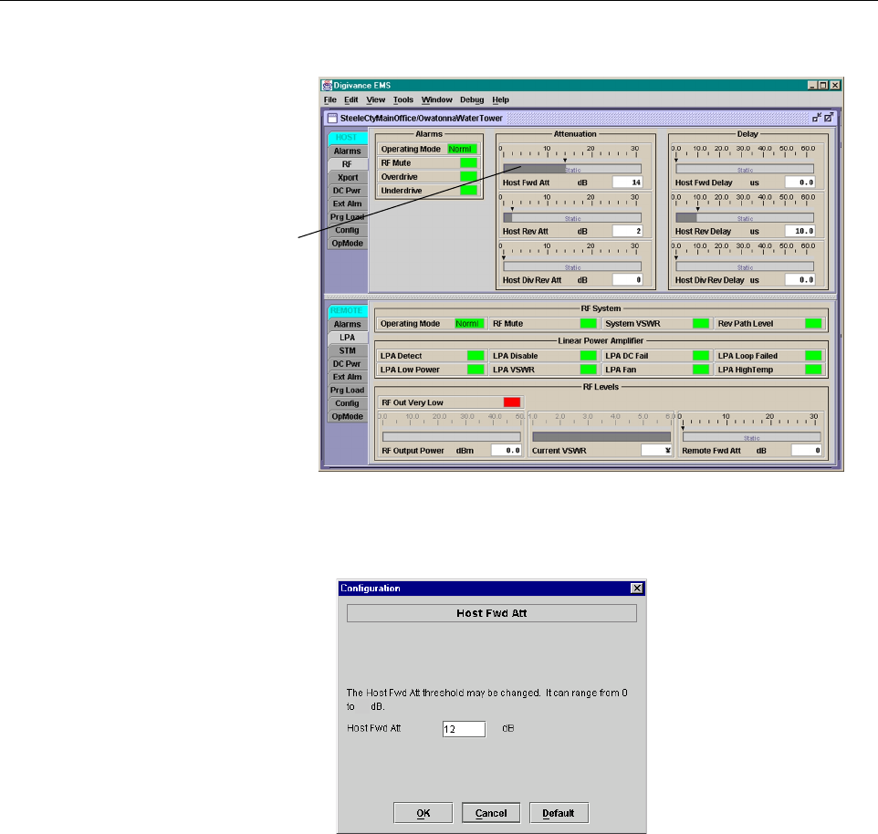
1. Click on the HOST RF tab. The HOST RF display will open within the EMS main
window as shown in Figure 4-8.
2. Right-click on the Host Fwd Att section of the display (see Figure 4-6). The Host Fwd
Att pop-up screen will open as shown in Figure 4-9.
3. Obtain the value of the total composite input signal level as determined in step 10 of
Section 2.3.
ADCP-75-134 • Issue A • April 2002 • Section 4: Operation
Page 4-11
©2002, ADC Telecommunications, Inc.
Figure 4-8. HOST RF Display
Figure 4-9. Host Fwd Att Pop-Up Screen
4. Determine the appropriate value to enter for the Host forward path attenuator by
subtracting the required system output level (per system design plan) from 80.85 (the total
system gain) and then adding the composite input signal level. The result (see sample
calculation) is the amount of attenuation required.
Atten Required =80.85 –(Required System Output Power) +(Composite Input Power)
5. Enter the attenuation value and click OK to close the pop-up screen and to make the
changes take effect.
Right-click here
to open Host Fwd
Att pop-up screen
20

ADCP-75-134 • Issue A • April 2002 • Section 4: Operation
Page 4-12
©2002, ADC Telecommunications, Inc.
2.6 Determine Output Signal Level at DDS Antenna Ports
The RF output signal level should be measured at the DDS ANTENNA ports to verify that
maximum composite signal level is at the required level. Use the following procedure to
determine the power level:
1. Verify that RF ON/OFF switch on the LPA in the OFF position.
2. Disconnect the antenna cable from the DDS ANTENNA 1port.
3. Connect aspectrum analyzer or RF power meter to the DDS ANTENNA 1port. (Check
the input rating of the test equipment and insert aPAD if necessary.)
4. Place the RF ON/OFF switch on the LPA in the ON position.
5. Measure the RF level of asingle carrier, such as the control channel, in dBm. Make sure
the resolution bandwidth of the spectrum analyzer or power meter is narrow enough to
measure the power of the single 30 kHz channel only.
6. Calculate the total composite signal power using the following formula:
Ptot = Pc+10Log N
Where,
Ptot is the total composite power in dBm
Pcis the power per carrier in dBm as measured in step 2, and
Nis the total number of channels.
7. Record the result calculated in step 6.
8. Place the RF ON/OFF switch on the LPA in the OFF position.
9. Disconnect the spectrum analyzer or RF power meter from the DDS ANTENNA 1port.
10. Re-connect the antenna cable to the DDS ANTENNA 1port.
11. Repeat procedure for the DDS ANTENNA 2port.
2.7 Enter Remote Forward Attenuation
The STM internal forward path attenuator setting is used to increase or reduce the power level
of the composite output signal level at the DDS antenna ports. The maximum composite output
signal level at the DDS antenna ports is set using the Host internal forward attenuator (see
Section 2.4). However, component variations may result in the output power at the DDS antenna
ports being slightly above or below the required power per channel. If this is the case, the STM
forward attenuator may be used in conjunction with the Host forward attenuator to add or
remove attenuation to produce the required output signal level. If less power is required, the
STM forward attenuator may be used to reduce the power level. The default setting is 0dB. Use
the following procedure to change the STM forward attenuation:
Note: To comply with Maximum Permissible Exposure (MPE) requirements, the
maximum composite output from the antenna(s) cannot exceed 1000 Watts EIRP and the
antenna(s) must be permanently installed in afixed location that provides at least 6meters
(20 feet) of separation from all persons.
ADCP-75-134 • Issue A • April 2002 • Section 4: Operation
Page 4-13
©2002, ADC Telecommunications, Inc.
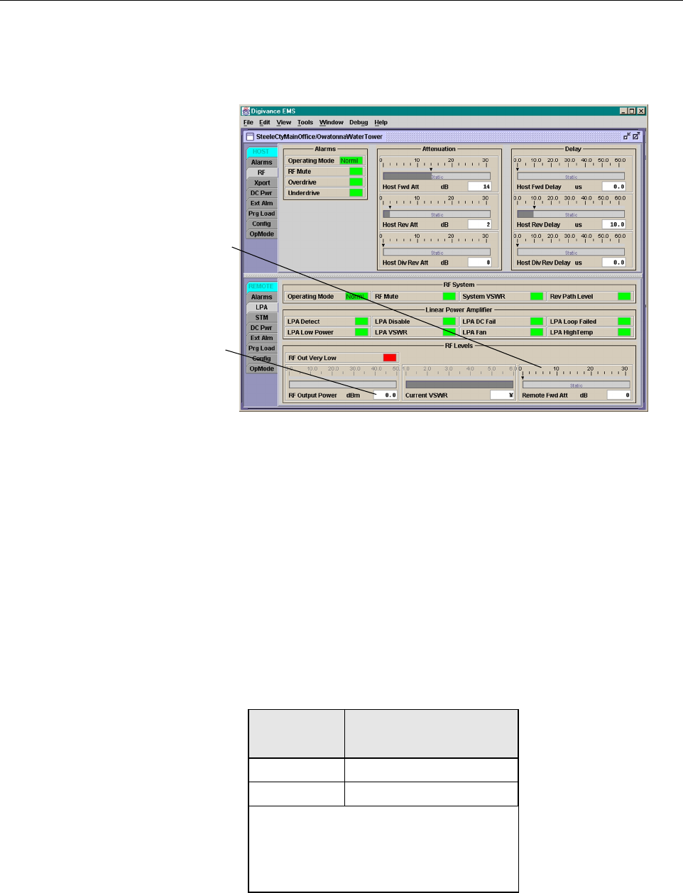
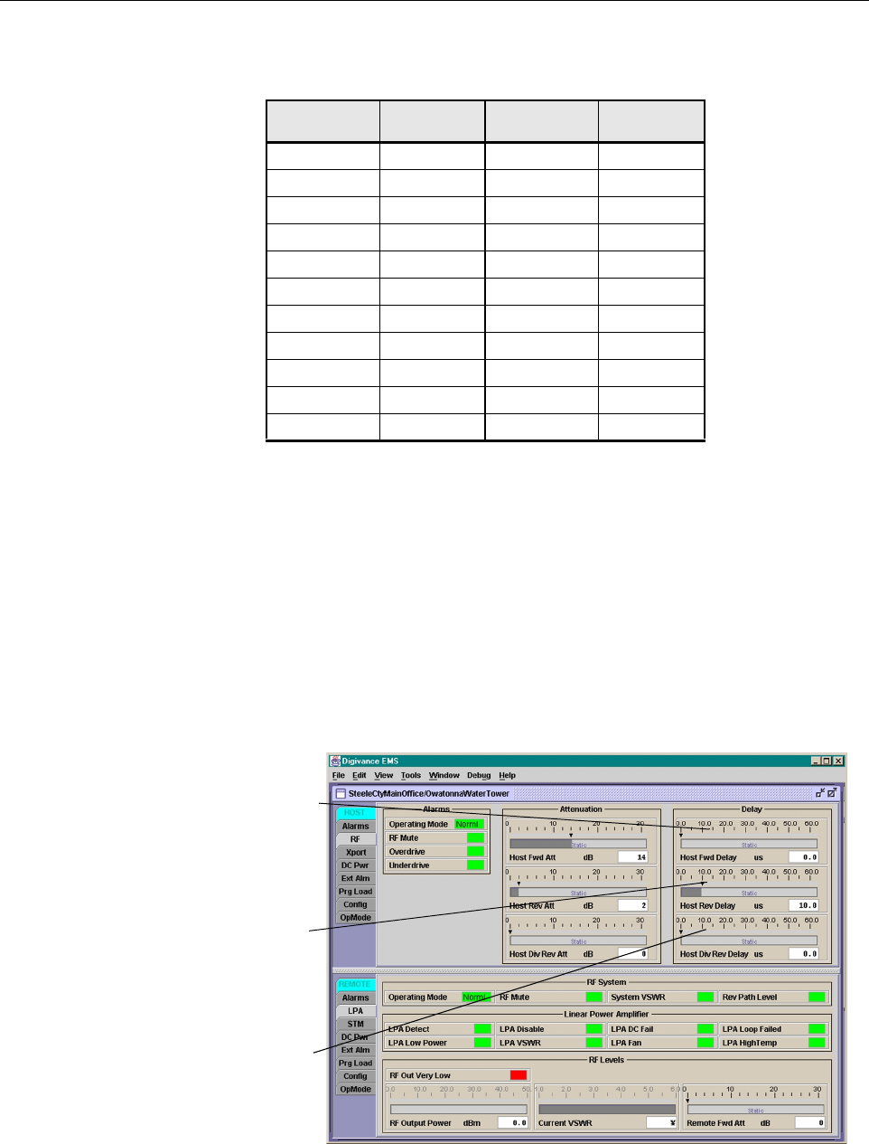
1. Click on the REMOTE LPA tab. The REMOTE LPA display will open within the EMS
main window as shown in Figure 4-10.
Figure 4-10. REMOTE LPA Display
2. Check the level of the RF output signal (as determined in Section 2.6)against the system
design plan specifications. Table 4-1 shows the output signal level required to provide 5
watts per channel. The maximum output signal level provided by the system is 40.85 dBm
(12 watts) at each DDS antenna port.
3. Determine if more or less attenuation is required to produce the required output signal level.
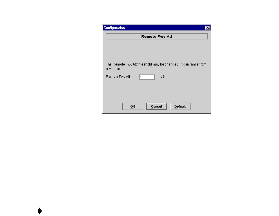
4. Right-click on the Remote Fwd Att section of the display (see Figure 4-10). The Remote
Fwd Att pop-up screen will open as shown in Figure 4-11.
Table 4-1. Composite Output Signal Levels
NUMBER OF
CHANNELS
OUTPUT SIGNAL LEVEL
REQUIRED TO PROVIDE 5
WATTS PER CHANNEL
137dBm
240dBm
When there are three or more channels, each
channel will always be less than 5watts per
channel because the system has amaximum
power output of 12 watts (40.85 dBm) per
DDS antenna port.
Right-click here to
open the Remote Fwd
Att pop-up screen
RF output signal level
ADCP-75-134 • Issue A • April 2002 • Section 4: Operation
Page 4-14
©2002, ADC Telecommunications, Inc.
Figure 4-11. Remote Fwd Att Pop-Up Screen
5. Enter the required attenuation value and click OK to close the pop-up screen and to make
the changes take effect.
6. Verify that the appropriate RF output signal level appears in the RF Pwr-VSWR Low
section (see Figure 4-10). This is primarily areference value and should not take the place
of external test equipment when determining the power level of the composite RF output
signal. Depending on the modulation type and number of channels, the EMS software may
report apower level that is higher or lower than the actual RF output signal.
2.8 Enter Host Reverse Attenuation
The level of the RF signal that should be input to the EBTS will vary depending on the type of
EBTS, the receive distribution, and the number of channels present. To interface with the EBTS,
the reverse path signal level must be adjusted to provide the signal level required by the EBTS.
The HU provides from 10 to 30 dB of gain in the reverse path. Use the following procedure to
set the reverse path gain:
1. Check the EBTS manufacturer’s specifications to determine the composite signal level
required at the EBTS reverse path input port.
2. Determine the overall gain and loss imposed on the signal by the antenna, antenna cable,
and by the cables that connect the HU to the EBTS.
3. Determine the amount of gain required to raise the reverse path signal to the level required
at the EBTS.
4. Click on the HOST RF tab. The HOST RF display will open within the EMS main
window as shown in Figure 4-12.
Note: To comply with Maximum Permissible Exposure (MPE) requirements, the
maximum composite output from the antenna(s) cannot exceed 1000 Watts EIRP and the
antenna(s) must be permanently installed in afixed location that provides at least 6meters
(20 feet) of separation from all persons.
20
ADCP-75-134 • Issue A • April 2002 • Section 4: Operation
Page 4-15
©2002, ADC Telecommunications, Inc.
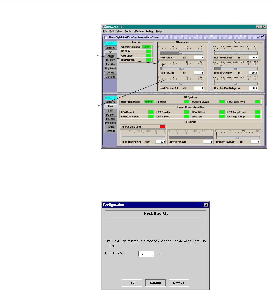
Figure 4-12. HOST RF Display
5. Right-click on the Host Rev Att section of the display (see Figure 4-12). The Host Rev
Att pop-up screen will open as shown in Figure 4-13.
Figure 4-13. Host Rev Att Pop-Up Screen
6. Enter the attenuation value that will provide the required gain. Refer to Table 4-2 for the
attenuation values and the corresponding gain values.
7. Click OK to close the pop-up screen and to make the changes take effect.
8. Repeat the process for the diversity reverse path by right-clicking on the Host Div Rev Att
section (see Figure 4-12)and then entering the required attenuation value in the Host Div
Rev Att pop-up screen.
9. Click OK to close the pop-up screen and to make the changes take effect.
Right-click here to
open the Host Rev Att
pop-up screen
Right-click here to
open the Host Div Rev
Att pop-up screen
20
ADCP-75-134 • Issue A • April 2002 • Section 4: Operation
Page 4-16
©2002, ADC Telecommunications, Inc.
2.9 Enter Host Forward and Reverse Delay
The forward and reverse delay function allows entry of from 0to 63 µsec of delay in the
forward and reverse paths. This feature is used when multiple systems are used to transport the
same channel and there is asignificant difference in the path delay between systems. Additional
delay may be entered to balance the overall system delay. The amount of delay required must be
calculated by the RF engineer and should be included in the system design plan. The default
setting is 0µsec. Use the following procedure to change the forward and reverse path delay:
1. Click on the HOST RF tab. The HOST RF display will open within the EMS main
window as shown in Figure 4-14.
Figure 4-14. HOST RF Display
Table 4-2. Reverse Path Setting
ATTENUATION
SETTING
GAIN
PROVIDED
ATTENUATION
SETTING
GAIN
PROVIDED
0dB →30 dB 11 dB →19 dB
1dB 29 dB 12 dB 18 dB
2dB 28 dB 13 dB 17 dB
3dB 27 dB 14 dB 16 dB
4dB 26 dB 15 dB 15 dB
5dB 25 dB 16 dB 14 dB
6dB 24 dB 17 dB 13 dB
7dB 23 dB 18 dB 12 dB
8dB 22 dB 19 dB 11 dB
9dB 21 dB 20 dB 10 dB
10 dB 20 dB - -
Right-click here to
open the Host Fwd
Delay pop-up screen
Right-click here to
open the Host Rev
Delay pop-up screen
Right-click here to
open the Host Div Rev
Delay pop-up screen
ADCP-75-134 • Issue A • April 2002 • Section 4: Operation
Page 4-17
©2002, ADC Telecommunications, Inc.
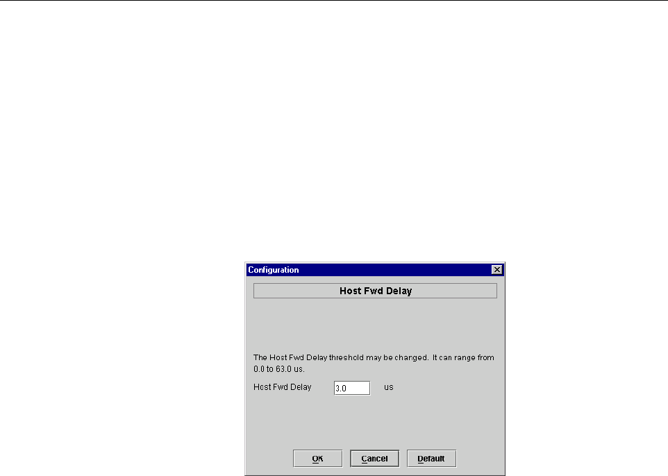
2. Right-click on the Host Fwd Delay section of the display (see Figure 4-14). The Host
Fwd Delay pop-up screen will open as shown in Figure 4-15.
3. Obtain the value of the forward delay as specified in the system design plan.
4. Enter the forward path delay value and click OK to close the pop-up screen and to make
the changes take effect.
5. Repeat the process for reverse delay and diversity reverse delay by right-clicking on the
appropriate delay section (see Figure 4-14)and then entering the required delay value in
the pop-up screen.
6. Click OK to close each pop-up screen and to make the changes take effect.
Figure 4-15. Host Fwd Delay Pop-Up Screen

ADCP-75-134 • Issue A • April 2002 • Section 4: Operation
Page 4-18
©2002, ADC Telecommunications, Inc.
Blank

ADCP-75-134 • Issue A • April 2002 • Section 5: Maintenance
Page 5-1
©2002, ADC Telecommunications, Inc.
SECTION 5: MAINTENANCE
1 SYSTEM MAINTENANCE OVERVIEW . . . . . . . . . . . . . . . . . . . . . . . . . . . . . . . . . . . . . . . . . . . . . . . . . . . . . . . . . .5-1
1.1 Tools and Materials . . . . . . . . . . . . . . . . . . . . . . . . . . . . . . . . . . . . . . . . . . . . . . . . . . . . . . . . . . . . . . .5-1
2 FAULT DETECTION AND ALARM REPORTING. . . . . . . . . . . . . . . . . . . . . . . . . . . . . . . . . . . . . . . . . . . . . . . . . . . .5-2
3 FAULT ISOLATION AND TROUBLESHOOTING. . . . . . . . . . . . . . . . . . . . . . . . . . . . . . . . . . . . . . . . . . . . . . . . . . . .5-6
4 TEST PROCEDURES. . . . . . . . . . . . . . . . . . . . . . . . . . . . . . . . . . . . . . . . . . . . . . . . . . . . . . . . . . . . . . . . . . . . 5-11
4.1 Optical Power Test. . . . . . . . . . . . . . . . . . . . . . . . . . . . . . . . . . . . . . . . . . . . . . . . . . . . . . . . . . . . . . . 5-11
4.2 Optical Loopback Test . . . . . . . . . . . . . . . . . . . . . . . . . . . . . . . . . . . . . . . . . . . . . . . . . . . . . . . . . . . . 5-12
5 MAINTENANCE PROCEDURES . . . . . . . . . . . . . . . . . . . . . . . . . . . . . . . . . . . . . . . . . . . . . . . . . . . . . . . . . . . . . 5-13
5.1 Scheduled Maintenance . . . . . . . . . . . . . . . . . . . . . . . . . . . . . . . . . . . . . . . . . . . . . . . . . . . . . . . . . . . 5-13
5.2 Remote Unit Cabinet Filter Cleaning Procedure . . . . . . . . . . . . . . . . . . . . . . . . . . . . . . . . . . . . . . . . . . . 5-14
5.3 Host Unit Fan Replacement Procedure . . . . . . . . . . . . . . . . . . . . . . . . . . . . . . . . . . . . . . . . . . . . . . . . . 5-15
5.4 Spectrum Transport Module Fan Replacement Procedure . . . . . . . . . . . . . . . . . . . . . . . . . . . . . . . . . . . . 5-17
5.5 Linear Power Amplifier Fan Replacement Procedure . . . . . . . . . . . . . . . . . . . . . . . . . . . . . . . . . . . . . . .5-19
_________________________________________________________________________________________________________
1 SYSTEM MAINTENANCE OVERVIEW
This section explains the Digivance LRCS fault detection and alarm reporting system, provides
amethod for isolating and troubleshooting faults, and provides test and maintenance
procedures. The Digivance LRCS requires minimal regular maintenance to insure continuous
and satisfactory operation. Components that require regular replacement, cleaning, or testing
include the HU and RU fans and the RU air-filter and back-up battery,
Maintenance also includes diagnosing and correcting service problems as they occur. When an
alarm is reported, it will be necessary to follow asystematic troubleshooting procedure to locate
the problem. Once the source of the problem is isolated, the appropriate corrective action can be
taken to restore service. The only internal components that can be replaced are the cooling fans
which mount in the HU, STM, and LPA. The failure of any other component within aunit will
required replacement of that unit.
1.1 Tools and Materials
The following tools and materials are required in order to complete the procedures in this
section:
•ESDwrist strap
•IRfiltering safety glasses
• Patch cords with SC connectors
•10dB in-line SC optical attenuators
•Opticalpower meter (1550 and 1310 nm)
• Laser light source
•TORXscrewdriver (with T10 bit)

ADCP-75-134 • Issue A • April 2002 • Section 5: Maintenance
Page 5-2
©2002, ADC Telecommunications, Inc.
•Batterymaintenance tools (see PRC-SERIES OPERATING AND FIELD SERVICE
MANUAL for tool recommendations)
2 FAULT DETECTION AND ALARM REPORTING
The Digivance LRCS on-board embedded software detects various unit and system faults and
reports them as either Major or Minor alarms. Amajor alarm indicates that the system has failed
in away that directly affects RF transport performance. This usually means that some calls or
perhaps all calls cannot be made over the system. AMinor alarm means that system
performance is not affected or in some cases, that the performance may no longer be optimal.
Four types of faults cause aminor alarm to be reported: overtemperature, fan failure, diversity
path failure, and an external minor fault (user defined fault). All other faults are reported as a
Major alarm.
Reporting of Major and Minor alarms is accomplished through the HU alarm contacts, the unit
front panel LED’s, the EMS software Maintenance Interface (MI), and the Network Operations
Center -Network Element Manager (NOC/NEM) interface.
The HU is equipped with aset of both normally open (NO) and normally closed (NC) alarm
contacts which are used to report both Major and Minor alarms to an external alarm system. The
alarm contacts summarize the inputs so that any Major or Minor alarm will trigger an alarm
report to the external alarm system.
The HU, STM, and LPA front panel LED indicators are used to indicate unit and system status
and to convey alarm information. In addition to LED indicators, the LPA is also equipped with a
Digital Display that provides status messages. Adescription of the Host Unit, Spectrum
Transport Module, and Linear Power Amplifier LED indicators is provided respectively in
Table 5-1,Table 5-2,and Table 5-3.
The EMS software MI provides both asummary and amore detailed list of alarm information
that includes unit and module level faults, circuit faults, and measured value faults such as
voltages, RF power, and temperature. Asummary showing alist of all systems and their current
alarm status is presented through the Alarm OverView display. Adetailed list of alarm
information is presented through the HOST alarm display and the REMOTE alarm display. All
the inputs that the system reports as alarms are shown in the HOST and REMOTE alarm
displays.
The NOC/NEM interface provides the same summary and detailed list of alarm information as
the EMS software MI but in an ASCII text string format. Sending the command GET
ALARMSUMMARY produces alist of all systems and their current alarm status. Sending the
command GET ALARM ALL for aspecific system will produce adetailed list of alarm
information for the specified system.

ADCP-75-134 • Issue A • April 2002 • Section 5: Maintenance
Page 5-3
©2002, ADC Telecommunications, Inc.
Table 5-1. Host Unit LED Indicators
INDICATOR COLOR DESCRIPTION
POWER
Green
Off
Indicates if the HU is powered or un-powered.
The DC power source is on.
The DC power source is off.
STANDBY
Green (blinking)
Yellow (blinking)
Red (blinking)
Off
Indicates if the HU is in the standby, normal, test, or pro-
gram load mode.
The HU is in the standby mode.
The HU is in the program load mode.
The HU is in the test mode.
The HU is in the normal mode.
HOST UNIT
Green
Yellow
Red
Indicates if the HU is normal, overheated, or faulty.
The HU is normal.
High temperature detected in HU.
Internal fault detected in the HU.
REMOTE UNIT
Green
Yellow
Red
Indicates if an alarm is detected at the RU.
No alarms detected at the RU.
Aminor alarm is detected at the RU.
Amajor alarm is detected at the RU.
DRIVE
Green
Yellow
Red
Indicates if the forward path RF signal level is normal,
above overdrive threshold, or below underdrive threshold.
The RF signal level is normal
The RF signal level is below the underdrive threshold.
The RF signal level is above the overdrive threshold.
PORT 1/PORT 2
Green
Red
Indicates if the reverse path optical signal received from
the RU is normal, if no signal is detected, or if errors are
detected.
The reverse path optical signal is normal.
No reverse path optical signal is received or excessive errors
are detected.
PORT 3
(diversity units
only) Green
Yellow
Indicates if the diversity reverse path optical signal
received from the RU is normal, if no signal is detected, or
if errors are detected.
The diversity reverse path optical signal is normal.
No diversity reverse path optical signal is received or exces-
sive errors are detected.

ADCP-75-134 • Issue A • April 2002 • Section 5: Maintenance
Page 5-4
©2002, ADC Telecommunications, Inc.
Table 5-2. Spectrum Transport Module LED Indicators
INDICATOR COLOR DESCRIPTION
AC POWER
Green
Red
Indicates if the STM is powered by the AC power source or
the back-up battery system.
The STM is powered by the AC power source.
The STM is powered by the back-up battery system.
STANDBY
Green (blinking)
Yellow (blinking)
Red (blinking)
Off
Indicates if the STM is in the standby, normal, test, or pro-
gram load mode.
The STM is in the standby mode.
The STM is in the program load mode.
The STM is in the test mode.
The STM is in the normal mode.
HOST UNIT
Green
Yellow
Red
Indicates if an alarm is detected at the HU.
No alarms detected at the HU.
Aminor alarm is detected at the HU.
Amajor alarm is detected at the HU.
STM
Green
Yellow
Red
Indicates if the STM is normal or faulty.
The STM is normal.
The STM is over temperature or the fan has failed.
Internal fault detected in the STM.
PA
Green
Yellow
Red
Indicates if the LPA is normal, over temperature, has afan
failure, or is faulty.
The LPA is normal.
The LPA is over temperature or the fan has failed.
Internal fault detected in the LPA.
VSWR
Green
Red
Indicates if the forward path VSWR is above or below the
threshold.
The VSWR is below the threshold.
The VSWR is above the threshold.
PORT 1/PORT 2
Green
Red
Indicates if the forward path optical signal received from
the HU is normal, if no signal is detected, or if errors are
detected.
The forward path optical signal is normal.
No forward path optical signal is received or excessive errors
are detected.
PORT 3
(diversity units
only) Green
Yellow
Indicates if the diversity reverse path optical signal
received by the HU is normal, if no signal is detected, or if
errors are detected.
The diversity reverse path optical signal is normal.
No diversity reverse path optical signal is received or exces-
sive errors are detected.

ADCP-75-134 • Issue A • April 2002 • Section 5: Maintenance
Page 5-5
©2002, ADC Telecommunications, Inc.
Table 5-3. Linear Power Amplifier LED Indicators and Digital Display
INDICATOR COLOR DESCRIPTION
FAIL
Off
Yellow
Indicates if the LPA is normal or faulty.
The LPA is normal.
Internal fault detected in the LPA.
SHUTDOWN
Off
Red
Indicates if the LPA has an RF output or if the RF output
is shutdown.
The LPA RF output is on.
The LPA RF output is shutdown.
DISPLAY MESSAGE DESCRIPTION
ADC850
0ALARMS
NORMAL OPERATION
The LPA is normal.
HUNG CHANG
ADC-850M Appears every time power is turned on.
RESTART AT STAND
ALONE MODE
Appears when LPA is reset.
ADC-850S Appears when an alarm has turned off and the LPA is restart-
ing after the RESET button has been pressed or the reset com-
mand has been supplied from an external source.
PLEASE WAIT WHILE
RESTARTING Appears while the LPA processor is rebooting.
DC +12V: +12.0V
DC +27V: +27.0V
DC +32V: +32.0V
DC -12V: -12.0V
Alternately displays the voltage flow in each part of the LPA.
TEMPER 100.0 ºC Indicates the current temperature of the LPA heat sink.
OVER POWER ALARM Output power has exceeded 100 W.
HIGH TEMPERATURE Alarm: Temperature of LPA exceeds 85 ºC.
VSWR ALARM Reflected LPA power exceeds 20 W.
LOOP FAIL General fault occurred in the LPA loops.
FANFAIL One or more fans have failed.
FORCED SHUTDOWN The RF ON/OFF switch is in the OFF position or the LPA was
set in the disable mode through the EMS computer.
Alternating FORCED SHUTDOWN
and alarm message An alarm has remained for over 5seconds.
DC FAIL
+12V
-12V
+32V
Vo l ta g e is outside the preset ranges:
+11 to +13V
-13 to -11V
+30 to +34V

ADCP-75-134 • Issue A • April 2002 • Section 5: Maintenance
Page 5-6
©2002, ADC Telecommunications, Inc.
3 FAULT ISOLATION AND TROUBLESHOOTING
Alarm information may be accessed and faults isolated using the information provided by the
unit front panel LED indicators, the EMS software MI alarm displays, or the NOC-EMS
interface. Because the alarm information provided by the EMS software MI and the NOC-EMS
interface is very detailed, refer to Table 5-4 or Table 5-5 to determine the unit LED indicator
(Host Unit or Remote Unit) that corresponds to the indicated alarm. Then refer to Table 5-6 or
Table 5-7 to identify the problem, check out the possible causes, and take corrective action.
Table 5-4. Host Unit Major and Minor Alarms
MAJOR ALARM LED INDICATOR MAJOR ALARM LED INDICATOR
Operating Mode (Does not apply) Fwd Synth Lock HOST UNIT
3.8 Volt HOST UNIT Sec Rev Synth Lock HOST UNIT
Pri Laser Fail HOST UNIT Overdrive DRIVE
Pri Errors PORT 1/PORT 2MINOR ALARMS LED INDICATOR
Pri Fwd Mux Lock HOST UNIT Underdrive DRIVE
Pri Rev Synth Lock HOST UNIT Temperature HOST UNIT
RF Mute (Does not apply) Sec Errors PORT 3
8Volt HOST UNIT Sec No Light PORT 3
Pri No Light PORT 1/PORT 2MajorExtern Output (Does not apply)
Table 5-5. Remote Unit Major and Minor Alarms
MAJOR ALARM LED INDICATOR MAJOR ALARM LED INDICATOR
Operating Mode (Does not apply) Pri Rev Synth Lock STM
Converter STM RF Mute (Does not apply)
Pri Laser Fail STM LPA Detect PA
Pri Rev Mux Lock STM LPA Low Power PA
Reference Synth Lock STM Major Extern Alarm Inp (Does not apply)
System VSWR VSWR MINOR ALARM LED INDICATOR
LPA DC Fail PA Sec Rev Synth Lock STM
LPA Over Power PA Rev Path Level (Does not apply)
AC Fail AC POWER Temperature STM
3.8 Volt STM Sec Laser Fail STM
Pri No Light PORT 1/PORT 2SecRev Mux Lock STM
Fwd Synth Lock STM LPA Disable SHUTDOWN (LPA)
LPA Loop Failed PA LPA Fan PA
LPA VSWR PA LPA High Temp PA
Battery Voltage STM Minor Extern Alarm Inp (Does not apply)
8Vo l t S TM R F Out Very Low (Does not apply)
Pri Errors PORT 1/PORT 2– –

ADCP-75-134 • Issue A • April 2002 • Section 5: Maintenance
Page 5-7
©2002, ADC Telecommunications, Inc.
During normal HU operation, all LED’s should be green except the STANDBY LED which
should be Off.When aMinor alarm occurs, one or more of the LED’s will turn yellow.When a
Major alarm occurs, one or more of the LED’s will turn red.
Table 5-6. Host Unit Fault Isolation and Troubleshooting
Alarm Type LED Color
Minor HOST UNIT Yellow
PROBLEM: The HU is overheating.
POSSIBLE CAUSE CORRECTIVE ACTION/COMMENTS
1. Air intake or exhaust opening to HU chassis
is blocked
2. Ambient temperature >50º C/122º F.
3. Faulty fan.
1. Remove cause of air-flow blockage.
2. Reduce ambient temperature.
3. Replace HU fan (See Section 5.3).
Alarm Type LED Color
Minor REMOTE UNIT Yellow
PROBLEM: A minor alarm is detected at the RU.
POSSIBLE CAUSE CORRECTIVE ACTION/COMMENTS
1. The STM or LPA is overheating. 1. Check RU for alarms and refer to Table 5-7
Alarm Type LED Color
Minor DRIVE Yellow
PROBLEM: The RF input signal level is below the underdrive threshold.
POSSIBLE CAUSE CORRECTIVE ACTION/COMMENTS
1. Faulty coaxial connection between the
HU and the EBTS.
2. Incorrect attenuation in forward path RF coax-
ial link.
1. Check forward path signal level at the HU.
2. Check Host Forward Attenuator setting and
adjust if attenuation is too high.
Alarm Type LED Color
Major HOST UNIT Red
PROBLEM: Internal fault detected in HU.
POSSIBLE CAUSE CORRECTIVE ACTION/COMMENTS
1. The HU has failed. 1. Replace the HU.
Alarm Type LED Color
Major REMOTE UNIT Red
PROBLEM: A major alarm is detected at the RU.
POSSIBLE CAUSE CORRECTIVE ACTION/COMMENTS
1. The STM or LPA has failed, the STM is not
receiving aforward path optical signal, or the
RU cabinet door is open.
1. Check RU for alarms and refer to Table 5-7.

ADCP-75-134 • Issue A • April 2002 • Section 5: Maintenance
Page 5-8
©2002, ADC Telecommunications, Inc.
During normal STM operation, all LED’s should be green except the STANDBY LED which
should be Off.When aMinor alarm occurs, one or more of the LED’s will turn yellow.When a
Major alarm occurs, one or more of the LED’s will turn red.
During normal LPA operation, all LED’s should be Off.
Alarm Type LED Color
Major DRIVE Red
PROBLEM: The RF signal is above the overdrive threshold.
POSSIBLE CAUSE CORRECTIVE ACTION/COMMENTS
1. Incorrect attenuation in forward path RF
coaxial link. 1. Check Forward Attenuator setting and adjust if
attenuation is too low.
Alarm Type LED Color
Major PORT 1/PORT 2 Red
PROBLEM: No reverse path optical signal is received or excessive errors are detected.
POSSIBLE CAUSE CORRECTIVE ACTION/COMMENTS
1. Faulty reverse path optical link.
2. Faulty optical transmit port at the HU or faulty
optical receive port at the STM.
1. Test optical fiber. Clean connector if dirty. Repair
or replace optical fiber if faulty. (See Section 4.1).
2. Test optical ports. Replace HU or STM if port is
faulty (See Section 4.2).
Alarm Type LED Color
Minor PORT 3 Yellow
PROBLEM: No diversity reverse path optical signal is received or excessive errors are detected.
POSSIBLE CAUSE CORRECTIVE ACTION/COMMENTS
1. Faulty diversity reverse path optical link.
2. Faulty optical transmit port at the HU or faulty
optical receive port at the STM.
1. Test optical fiber. Clean connector if dirty. Repair
or replace optical fiber if faulty. (See Section 4.1)
2. Test optical ports. Replace HU or STM if port is
faulty (See Section 4.2).
Table 5-7. STM and LPA Fault Isolation and Troubleshooting
Alarm Type LED Color
Minor STM Yellow
PROBLEM: The STM is overheating.
POSSIBLE CAUSE CORRECTIVE ACTION/COMMENTS
1. Air intake or exhaust opening to the remote
unit cabinet is blocked
2. Ambient temperature >50º C/122º F.
3. Faulty fan.
1. Remove cause of air-flow blockage.
2. Reduce ambient temperature.
3. Replace STM fan (See Section 5.4).
Table 5-6. Host Unit Fault Isolation and Troubleshooting, continued

ADCP-75-134 • Issue A • April 2002 • Section 5: Maintenance
Page 5-9
©2002, ADC Telecommunications, Inc.
Alarm Type LED Color
Minor HOST UNIT Yellow
Problem: A minor alarm is detected at the HU.
POSSIBLE CAUSE CORRECTIVE ACTION/COMMENTS
1. The HU is overheating. 1. Check HU for alarms and refer to Table 5-6
Alarm Type LED Color
Minor PA Yellow
PROBLEM: The LPA is overheating.
POSSIBLE CAUSE CORRECTIVE ACTION/COMMENTS
1. Air intake or exhaust opening to the remote
unit cabinet is blocked
2. Ambient temperature >50º C/122º F.
3. Faulty fan.
1. Remove cause of air-flow blockage.
2. Reduce ambient temperature.
3. Replace LPA fan (See Section 5.5).
Alarm Type LED Color
Major AC POWER Red
PROBLEM: The RU is powered by the back-up battery system
POSSIBLE CAUSE CORRECTIVE ACTION/COMMENTS
1. The AC power system circuit breaker is open
or the AC power has failed. 1. Check the AC power system, repair as needed,
and reset circuit breaker.
Alarm Type LED Color
Major HOST UNIT Red
PROBLEM: A major alarm is detected at the HU.
POSSIBLE CAUSE CORRECTIVE ACTION/COMMENTS
1. The HU has failed. 1. Check HU for alarms and refer to Table 5-6.
Alarm Type LED Color
Major STM Red
PROBLEM: Internal fault detected in STM.
POSSIBLE CAUSE CORRECTIVE ACTION/COMMENTS
1. The STM has failed. 1. Replace the STM.
Alarm Type LED Color
Major PA Red
PROBLEM: Internal fault detected in LPA.
POSSIBLE CAUSE CORRECTIVE ACTION/COMMENTS
1. The LPA has failed. 1. Replace the LPA.
Table 5-7. STM and LPA Fault Isolation and Troubleshooting, continued

ADCP-75-134 • Issue A • April 2002 • Section 5: Maintenance
Page 5-10
©2002, ADC Telecommunications, Inc.
Alarm Type LED Color
Major VSWR Red
PROBLEM: The forward path VSWR is above the threshold.
POSSIBLE CAUSE CORRECTIVE ACTION/COMMENTS
1. Faulty antenna. 1. Check the antenna circuit for shorts or opens
(including lightning protector).
Alarm Type LED Color
Major PORT 1/PORT 2 Red
PROBLEM: No forward path optical signal is received or excessive errors are detected.
POSSIBLE CAUSE CORRECTIVE ACTION/COMMENTS
1. Faulty forward path optical link.
2. Faulty optical transmit port at the STM or
faulty optical receive port at the HU.
1. Test optical fiber. Clean connector if dirty. Repair
or replace optical fiber if faulty. (See Section 4.1).
2. Test optical ports. Replace HU or STM if port is
faulty (See Section 4.2).
Alarm Type LED Color
Minor PORT 3 Yellow
PROBLEM: No diversity reverse path optical signal is received by the HU or excessive errors are detected.
POSSIBLE CAUSE CORRECTIVE ACTION/COMMENTS
1. Faulty diversity reverse path optical link.
2. Faulty optical transmit port at the STM or
faulty optical receive port at the HU.
1. Test optical fiber. Clean connector if dirty. Repair
or replace optical fiber if faulty. (See Section 4.1).
2. Test optical ports. Replace HU or STM if port is
faulty (See Section 4.2).
Alarm Type LED Color
Major FAIL Yellow
PROBLEM: Internal fault detected in the LPA.
POSSIBLE CAUSE CORRECTIVE ACTION/COMMENTS
1.The LPA has failed. 1. Replace LPA
Alarm Type LED Color
Major SHUTDOWN Red
PROBLEM: The RF output from the LPA is shutdown.
POSSIBLE CAUSE CORRECTIVE ACTION/COMMENTS
1.The RF ON/OFF switch is in the OFF position
or the LPA was set in the disable mode through
the EMS computer.
2. Breaker switch on LPA is open
3. The LPA is faulty.
1.Place RF ON/OFF switch in the ON position or
enable the LPA.
2. Reset breaker switch.
3. Replace LPA.
Table 5-7. STM and LPA Fault Isolation and Troubleshooting, continued

ADCP-75-134 • Issue A • April 2002 • Section 5: Maintenance
Page 5-11
©2002, ADC Telecommunications, Inc.
4 TEST PROCEDURES
This section provides procedures for common troubleshooting and maintenance tests. Refer to
these procedures as needed when specified in the Fault Isolation and Troubleshooting tables in
Section 3.
4.1 Optical Power Test
Abreak in an optical fiber or afault with the optical connector will interrupt communications
between linked components or generate excessive errors. Use the following procedure to isolate
aproblem with an optical fiber or connector.
1. Put on the IR filtering safety glasses.
2. Notify the NOC or alarm monitoring system operator that the system is going offline.
3. At the HU and at the STM, place the On/Off switch in the OFF position (press O).
4. Disconnect the optical fiber connectors for the fiber to be tested at the HU and at the STM.
5. Inspect the optical connectors. Verify that each connector is clean and that no scratches or
imperfections are visible on the fiber end. Clean and polish the optical connector if
necessary.
6. Connect alaser light source to one end of the optical fiber and an optical power meter to
the other end.
7. Verify that the power loss is within specifications. The optical loss budget for 9/125,
single-mode, dark fiber is 17 dB (typical). The optical power level should not exceed
–7 dBm to avoid overdriving the optical receiver. If the power loss is not within
specifications, repair or replace the optical fiber and/or connector per local practice.
8. Repeat steps 3through 6for each optical fiber that requires testing.
9. Reconnect the optical fibers at the HU and the STM.
10. When ready to put the system back into service, place the On/Off switch in the ON
position (press I)at both the HU and STM.
11. Notify the NOC or alarm monitoring service that the system is going back online.
Danger: This equipment uses aClass 1Laser according to FDA/CDRH rules. Laser radiation
can seriously damage the retina of the eye. Do not look into the ends of any optical fiber. Do not
look directly into the optical transmitter of any unit or exposure to laser radiation may result.
An optical power meter should be used to verify active fibers. Aprotective cap or hood MUST
be immediately placed over any radiating transmitter or optical fiber connector to avoid the
potential of dangerous amounts of radiation exposure. This practice also prevents dirt particles
from entering the connector.

ADCP-75-134 • Issue A • April 2002 • Section 5: Maintenance
Page 5-12
©2002, ADC Telecommunications, Inc.
4.2 Optical Loopback Test
Afaulty optical port, abreak in an optical fiber, or afault in an optical connector will interrupt
communications between fiber linked components. The following procedures provide tests to
determine if afault exists with the primary optical ports (PORT 1/PORT 2) or with the
secondary optical port (PORT 3).
4.2.1 PORT 1/PORT 2 Loopback Test
1. Put on the IR filtering safety glasses.
2. Notify the NOC or alarm monitoring system operator that the system is going offline.
3. At the HU or STM (whichever unit is being tested), place the On/Off switch in the OFF
position (press O).
4. Disconnect the optical fiber connectors from the PORT 1and PORT 2optical ports and
place adust cap over each connector.
5. Plug a10 dB in-line optical attenuator into the PORT 1optical port.
6. Connect apatch cord between the optical attenuator and the PORT 2optical port.
7. Place the On/Off switch in the ON position (press I)and observe the PORT 1/PORT 2
LED indicator.
8. The PORT 1/PORT 2LED indicator will turn either red or green. If the LED turns red, the
primary optical transmitter or receiver is faulty. Replace the unit and then recheck system
operation. If the LED turns green, the optical ports are good.
9. Place the On/Off switch in the OFF position (press O).
10. Remove the optical attenuator from the PORT 1optical port.
11. Remove the dust caps from the optical fiber connectors.
12. Clean each connector (follow connector supplier’s recommendations) and then insert each
connector into the appropriate optical port.
13. When ready to put the unit back into service, place the On/Off switch in the ON position
(press I).
14. Notify the NOC or alarm monitoring service that the system is going back online.
Danger: This equipment uses aClass 1Laser according to FDA/CDRH rules. Laser radiation
can seriously damage the retina of the eye. Do not look into the ends of any optical fiber. Do not
look directly into the optical transmitter of any unit or exposure to laser radiation may result.
An optical power meter should be used to verify active fibers. Aprotective cap or hood MUST
be immediately placed over any radiating transmitter or optical fiber connector to avoid the
potential of dangerous amounts of radiation exposure. This practice also prevents dirt particles
from entering the connector.

ADCP-75-134 • Issue A • April 2002 • Section 5: Maintenance
Page 5-13
©2002, ADC Telecommunications, Inc.
4.2.2 PORT 3 Loopback Test
1. Put on the IR filtering safety glasses.
2. Notify the NOC or alarm monitoring system operator that the system is going offline.
3. At the HU or STM (whichever unit is being tested), place the On/Off switch in the OFF
position (press O).
4. Disconnect the optical fiber connectors from the PORT 1and PORT 3optical ports and
place adust cap over each connector.
5. Plug a10 dB in-line optical attenuator into the PORT 3optical port.
6. Connect apatch cord between the optical attenuator and the PORT 1optical port.
7. Place the On/Off switch in the ON position (press I)and observe the PORT 3LED
indicator.
8. The PORT 3LED indicator will turn either red or green. If the LED turns yellow, the
secondary optical transmitter or receiver is faulty. Replace the unit and then recheck
system operation. If the LED turns green, the optical ports are good.
9. Place the On/Off switch in the OFF position (press O).
10. Remove the optical attenuator from the PORT 3optical port.
11. Remove the dust caps from the optical fiber connectors.
12. Clean each connector (follow connector supplier’s recommendations) and then insert each
connector into the appropriate optical port.
13. When ready to put the unit back into service, place the On/Off switch in the ON position
(press I).
14. Notify the NOC or alarm monitoring service that the system is going back online.
5 MAINTENANCE PROCEDURES
This section specifies the system maintenance requirements and provides the procedures for the
required maintenance tasks. Refer to these procedures as needed when specified in the
Scheduled Maintenance table.
5.1 Scheduled Maintenance
Table 5-8 lists the items that require regular maintenance and the recommended maintenance
interval. Refer to the section specified in the table for the required maintenance or test
procedure.

ADCP-75-134 • Issue A • April 2002 • Section 5: Maintenance
Page 5-14
©2002, ADC Telecommunications, Inc.
5.2 Remote Unit Cabinet Filter Cleaning Procedure
The RU cabinet filter cleans the RU intake air before it enters the cabinet. The filter should be
cleaned approximately once per year and more often in extremely dirty environments. If the
cabinet temperature gradually rises over along period of time and there are no fan failures, it is
possible that the filter is dirty and requires cleaning. Use the following procedure to clean the
RU cabinet filter:
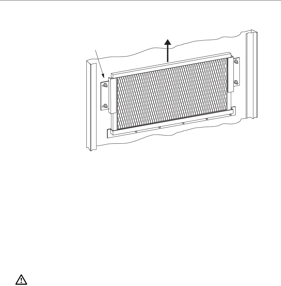
1. Open the RU cabinet door as shown in Figure 5-1.
2. Loosen the hex nuts that secure the left and right filter brackets to the cabinet door.
3. Pull the filter upward and away from the cabinet door. Be careful not to damage the gasket
that provides the air seal.
4. Gently tap the filter against your hand to dislodge the dirt. If necessary, use compressed air
or avacuum cleaner to remove the dirt.
5. Re-install the filter in the door and tighten the hex nuts that secure the left and right
brackets to the door.
Table 5-8. Scheduled Maintenance
INTERVAL ITEM REQUIREMENT
1month Battery* Check float voltage.
Check system ambient temperature.
Check system float current.
6months Battery* Perform 1month scheduled maintenance tasks.
Check individual battery terminal temperature.
Check individual battery float voltages.
12 months Battery *
RU cabinet filter**
Perform 1and 6month scheduled maintenance tasks
Complete detailed physical inspection.
Re-torque terminal connections.
Perform general system maintenance.
Perform cabinet maintenance.
Remove and clean the RU cabinet filter. Refer to Section 5.2
for the required procedure.
24 months Battery* Perform 1, 6, and 24 month scheduled maintenance tasks.
Test battery system for rated capacity.
60 months HU Fans
STM Fan
LPA Fans
Remove and replace the cooling fans in the HU, STM, and
LPA. Refer to specified section for the required procedures:
HU see Section 5.3,Section 5.4,and LPA see Section 5.5.
*Refer to the PRC-SERIES OPERATING AND FIELD SERVICE MANUAL (provided with the
back-up battery system) for the specified battery maintenance procedures.
**Though it is not recommended that the RU be installed in asalt-air environment, if done so, clean the
cabinet filter on amonthly basis instead of on a12 month basis. In addition, the RU should be
inspected for corrosion due to salt, particularly near the fans and around the connectors. The MTBF of
the RU may be impacted if the RU is exposed to salt-air.
ADCP-75-134 • Issue A • April 2002 • Section 5: Maintenance
Page 5-15
©2002, ADC Telecommunications, Inc.
Figure 5-1. Air Filter Removal and Replacement
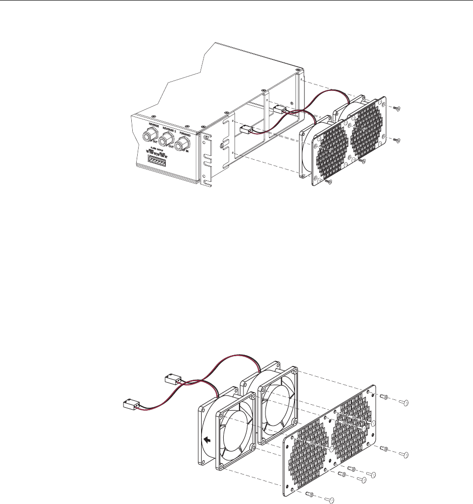
5.3 Host Unit Fan Replacement Procedure
The HU is equipped with two cooling fans which are located on the right side of the HU
enclosure. The cooling fans blow cool air into the enclosure. Heated air is exhausted through the
vent openings on the left side of the enclosure. Replacement of the fans requires that the HU be
turned off for ashort period of time. Use the following procedure to remove and replace the HU
cooling fans:
1. Before working on the HU or handling afan, slip on an Electro-Static Discharge (ESD)
wrist strap and connect the ground wire to an earth ground source. Wear the ESD wrist
strap while completing each section of the fan installation procedure.
2. Notify the NOC or alarm monitoring system operator that the system is going offline.
3. Place the HU On/Off switch in the OFF position (press O).
4. Remove the six flat-head screws (requires TORX screwdriver with T10 bit) that secure the
fan/grill assembly to the right side of the HU enclosure as shown in Figure 5-2.Save
screws for reuse.
Warning: Electronic components can be damaged by static electrical discharge. To prevent
ESD damage, always wear an ESD wrist strap when working on the HU, STM, or LPA and
when handling electronic components.
LOOSEN HEX NUTS ON BOTH
SIDES OF AIR FILTER
LIFT AIR FILTER UP AND
AWAY FROM DOOR
16983-A
ADCP-75-134 • Issue A • April 2002 • Section 5: Maintenance
Page 5-16
©2002, ADC Telecommunications, Inc.
Figure 5-2. Host Unit Fan/Grill Assembly Removal
5. Carefully withdraw the fan/grill assembly from the enclosure until the wiring harness is
exposed and the connectors are accessible.
6. Lift the small latch on each wiring harness connector and carefully unplug each connector
from the circuit board connector.
7. Remove the plastic rivets that secure each fan to the grill by pushing outward on the rivet
center post until the rivet can be withdrawn from the grill as shown in Figure 5-3.
Figure 5-3. Removing Host Unit Fans From Grill
8. Remove both fans from the grill
9. Use the rivets removed in step 7to secure the replacement fans to the grill. Orient each fan
so the wiring harness is on the top and the arrow on the fan points into the enclosure.
10. Connect the two wiring harness connectors to the circuit board connectors.
11. Secure the fan/grill assembly to the side of the enclosure (see Figure 5-2)using the six
flat-head screws removed in step 4.
16986-A
16173-B
ADCP-75-134 • Issue A • April 2002 • Section 5: Maintenance
Page 5-17
©2002, ADC Telecommunications, Inc.
12. Place the HU On/Off switch in the ON position (press I).
13. Verify that the fans run properly following power-up.
14. Notify the NOC or alarm monitoring system operator that the system is going back online.
5.4 Spectrum Transport Module Fan Replacement Procedure
The STM is equipped with arear cooling fan that exhausts heated air from the STM enclosure.
Cool air enters the STM through vent openings on the side of the enclosure. Replacement of the
fan requires that the STM be turned off for ashort period of time and that the STM be removed
from the cabinet. Use the following procedure to remove and replace the STM cooling fan.
1. Before working on the STM or handling afan, slip on an Electro-Static Discharge (ESD)
wrist strap and connect the ground wire to an earth ground source. Wear the ESD wrist
strap while completing each section of the fan installation procedure.
2. Notify the NOC or alarm monitoring system operator that the system is going offline.
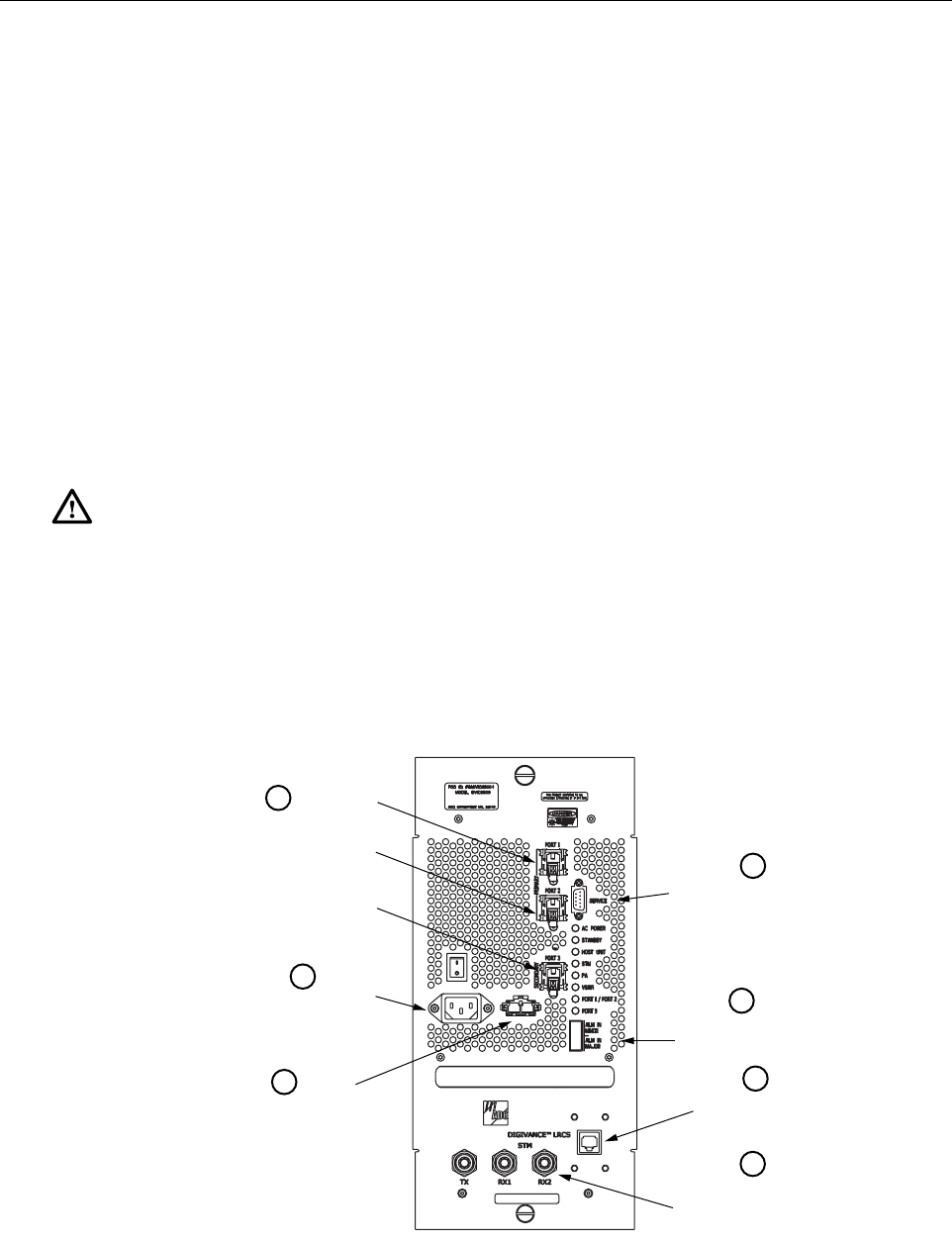
3. Place the STM On/Off switch in the OFF position (press O).
4. Disconnect the various power, fiber optic, service, alarm wiring, and coaxial cable
connectors from the STM front panel as specified in Figure 5-4.
Figure 5-4. Spectrum Transport Module Cable Connections
Warning: Electronic components can be damaged by static electrical discharge. To prevent
ESD damage, always wear an ESD wrist strap when working on the HU, STM, or LPA and
when handling electronic components.
17617-A
Disconnect AC
power connector
Disconnect back-up battery
DC power connector
Disconnect alarm
connector
Disconnect power
monitor cable
connector
Disconnect TX, RX1, and
RX2 coaxial cable
connectors
1
2
3
4
5
6
7
Disconnect optical fiber
connectors. Place a dust
cap over each cable
connector and port adapter. Disconnect service
connector (if present)
ADCP-75-134 • Issue A • April 2002 • Section 5: Maintenance
Page 5-18
©2002, ADC Telecommunications, Inc.
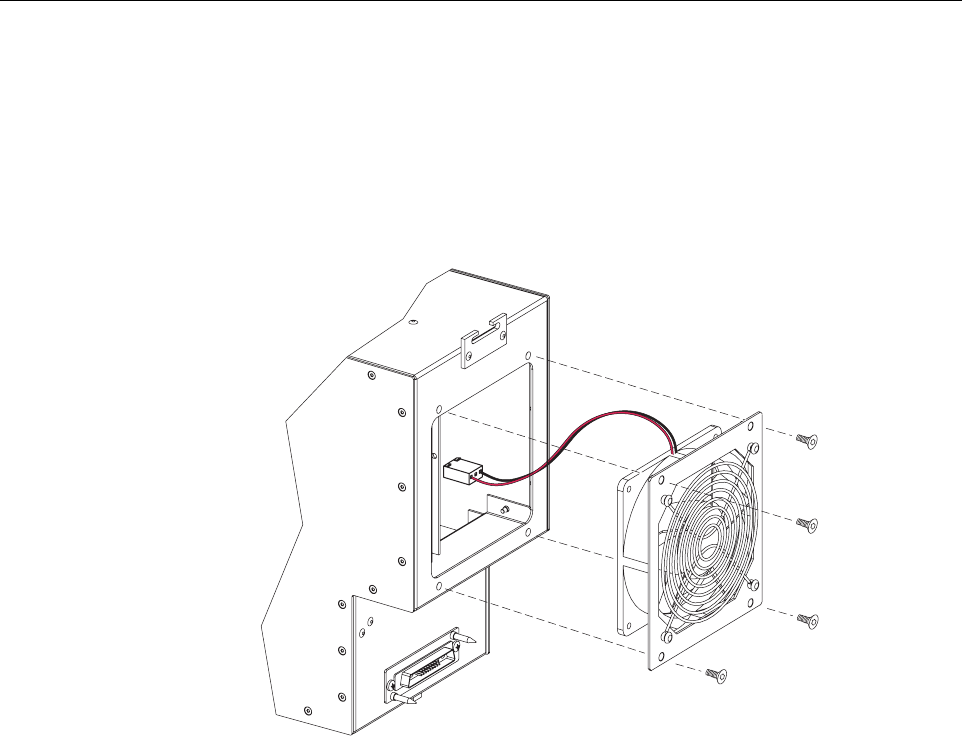
5. Loosen the captive screws that secure the STM to the RU cabinet mounting shelf and
carefully withdraw the STM from the cabinet.
6. Remove the four pan-head screws (requires TORX screwdriver with T10 bit) that secure
the fan/grill assembly to rear side of the STM enclosure as shown in Figure 5-5.Save
screws for reuse.
Figure 5-5. STM Fan/Grill Assembly Removal
7. Carefully withdraw the fan/grill assembly from the enclosure until the wiring harness is
exposed and the connector is accessible.
8. Lift the small latch on the wiring harness connector and carefully unplug the connector
from the circuit board connector.
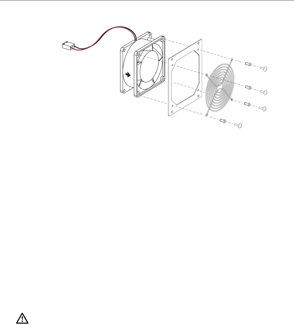
9. Remove the plastic rivets that secure the fan to the mounting plate and grill by pushing
outward on the rivet center post until the rivet can be withdrawn as shown in Figure 5-6.
10. Separate fan from the mounting plate and grill
11. Use the rivets removed in step 9to secure the replacement fan to the mounting plate and
grill. Orient the fan so the wiring harness is on the top and the arrow on the fan points
away from the enclosure. Make certain the rubber grommets are left in place on the
mounting plate.
12. Connect the wiring harness connector to the circuit board connector.
13. Secure the fan/grill assembly to the back of the enclosure (see Figure 5-5)using the four
pan-head screws removed in step 6. Do not overtighten the screws. The screw threads can
be easily stripped if too much torque is used to tighten the screws.
16992-A
ADCP-75-134 • Issue A • April 2002 • Section 5: Maintenance
Page 5-19
©2002, ADC Telecommunications, Inc.
Figure 5-6. Removing STM Fan From Mounting Plate and Grill
14. Re-install the STM in the cabinet and then re-connect all cables in the reverse order in
which they were disconnected (see Figure 5-4).
15. Place the STM On/Off switch in the ON position (press I).
16. Verify that the fan runs properly following power-up.
17. Notify the NOC or alarm monitoring system operator that the system is going back online.
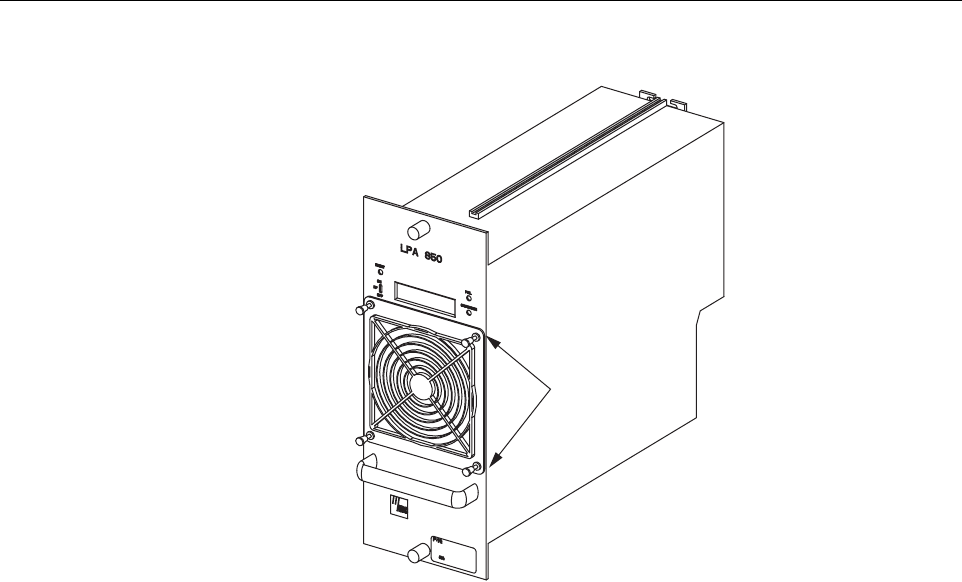
5.5 Linear Power Amplifier Fan Replacement Procedure
The LPA is equipped with both afront and rear cooling fan. The front fan draws cool air into the
LPA enclosure and the rear fan exhausts heated air from the LPA enclosure. Replacement of the
fans requires that the STM be turned off for ashort period of time and that the LPA be removed
from the cabinet. Use the following procedure to remove and replace the LPA cooling fans.
1. Before working on the LPA or handling afan, slip on an Electro-Static Discharge (ESD)
wrist strap and connect the ground wire to an earth ground source. Wear the ESD wrist
strap while completing each section of the fan installation procedure.
2. Notify the NOC or alarm monitoring system operator that the system is going offline.
3. Place the STM On/Off switch in the OFF position (press O).
4. Loosen the captive screws that secure the LPA to the RU cabinet mounting shelf and
carefully withdraw the LPA from the cabinet.
5. Pull out the four retainers that secure the front fan to the LPA as shown in Figure 5-7 and
same for reuse.
Warning: Electronic components can be damaged by static electrical discharge. To prevent
ESD damage, always wear an ESD wrist strap when working on the HU, STM, or LPA and
when handling electronic components.
16993-A
ADCP-75-134 • Issue A • April 2002 • Section 5: Maintenance
Page 5-20
©2002, ADC Telecommunications, Inc.
Figure 5-7. LPA Fan Removal and Replacement
6. Carefully withdraw the fan assembly from the LPA until the wiring harness is exposed and
the RJ-45 wiring harness connector is accessible.
7. Disconnect the fan wiring harness connector from the LPA and lift the fan assembly away
from the LPA.
8. Place asmall amount of anti-corrosion gel on the connector of the replacement fan
assembly.
9. Orient the fan assembly so the air-flow arrow points into the LPA.
10. Connect the fan assembly wiring harness connector to the LPA internal connector.
11. Secure the fan assembly to the LPA using the four retainers removed in step 5.
12. Replace the rear fan assembly using the same procedure covered in steps 5through 11
except orient the rear fan so the air-flow arrow is pointing away from the LPA.
13. When both fan assemblies have been replaced, re-install the LPA in the cabinet.
14. Place the STM On/Off switch in the ON position (press I)and verify that both fans operate
properly. The front fan should draw air into the LPA and the rear fan should blow air out of
the LPA.
15. Notify the NOC or alarm monitoring system operator that the system is going back online.
16994-A
PULL ON RETAINERS
TO REMOVE FAN

ADCP-75-134 • Issue A • April 2002 • Section 6: General Information
Page 6-1
©2002, ADC Telecommunications, Inc.
SECTION 6: GENERAL INFORMATION
1 WARRANTY/SOFTWARE . . . . . . . . . . . . . . . . . . . . . . . . . . . . . . . . . . . . . . . . . . . . . . . . . . . . . . . . . . . . . . . . . .6-1
2 SOFTWARE SERVICE AGREEMENT. . . . . . . . . . . . . . . . . . . . . . . . . . . . . . . . . . . . . . . . . . . . . . . . . . . . . . . . . . .6-1
3 REPAIR/EXCHANGE POLICY . . . . . . . . . . . . . . . . . . . . . . . . . . . . . . . . . . . . . . . . . . . . . . . . . . . . . . . . . . . . . . .6-1
4 REPAIR CHARGES . . . . . . . . . . . . . . . . . . . . . . . . . . . . . . . . . . . . . . . . . . . . . . . . . . . . . . . . . . . . . . . . . . . . . .6-2
5 REPLACEMENT/SPARE PRODUCTS . . . . . . . . . . . . . . . . . . . . . . . . . . . . . . . . . . . . . . . . . . . . . . . . . . . . . . . . . .6-2
6 RETURNED MATERIAL . . . . . . . . . . . . . . . . . . . . . . . . . . . . . . . . . . . . . . . . . . . . . . . . . . . . . . . . . . . . . . . . . . . 6-2
7 CUSTOMER INFORMATION AND ASSISTANCE . . . . . . . . . . . . . . . . . . . . . . . . . . . . . . . . . . . . . . . . . . . . . . . . . . .6-3
_________________________________________________________________________________________________________
1 WARRANTY/SOFTWARE
The Product and Software warranty policy and warranty period for all ADC Products is
published in ADC’s Warranty/Software Handbook. Contact the Infrastructure Division (ID)
Technical Assistance Center at 1-800-366-3891, extension 73475 (in U.S.A. or Canada) or
952-917-3475 (outside U.S.A. and Canada) for warranty or software information or for acopy
of the Warranty/Software Handbook.
2 SOFTWARE SERVICE AGREEMENT
ADC software service agreements for some ADC Products are available at anominal fee.
Contact the ID Technical Assistance Center at 1-800-366-3891, extension 73475 (in U.S.A. or
Canada) or 952-917-3475 (outside U.S.A. and Canada) for software service agreement
information.
3 REPAIR/EXCHANGE POLICY
All repairs of ADC Products must be done by ADC or an authorized representative. Any
attempt to repair or modify ADC Products without written authorization from ADC voids the
warranty.
If amalfunction cannot be resolved by the normal troubleshooting procedures, call the ID
Technical Assistance Center at 1-800-366-3891, extension 73475 (in U.S.A. or Canada) or
952-917-3475 (outside U.S.A. and Canada). Atelephone consultation can sometimes resolve a
problem without the need to repair or replace the ADC Product.
If, during atelephone consultation, ADC determines the ADC Product needs repair, ADC will
authorize the return of the affected Product for repair and provide aReturn Material
Authorization number and complete return shipping instructions. If time is critical, ADC can
arrange to ship the replacement Product immediately. In all cases, the defective Product must be
carefully packaged and returned to ADC.
Content Page

ADCP-75-134 • Issue A • April 2002 • Section 6: General Information
Page 6-2
©2002, ADC Telecommunications, Inc.
4 REPAIR CHARGES
If the defect and the necessary repairs are covered by the warranty, and the applicable warranty
period has not expired, the Buyer’s only payment obligation is to pay the shipping cost to return
the defective Product. ADC will repair or replace the Product at no charge and pay the return
shipping charges.
Otherwise, ADC will charge apercentage of the current Customer Product price for the repair
or NTF (No Trouble Found). If an advance replacement is requested, the full price of anew unit
will be charged initially. Upon receipt of the defective Product, ADC will credit Buyer with 20
percent of full price charged for any Product to be Out-of-Warranty. Products must be returned
within thirty (30) days to be eligible for any advance replacement credit. If repairs necessitate a
visit by an ADC representative, ADC will charge the current price of afield visit plus round trip
transportation charges from Minneapolis to the Buyer’s site.
5 REPLACEMENT/SPARE PRODUCTS
Replacement parts, including, but not limited to, button caps and lenses, lamps, fuses, and patch
cords, are available from ADC on aspecial order basis. Contact the ID Technical Assistance
Center at 1-800-366-3891, extension 73475 (in U.S.A. or Canada) or 952-917-3475 (outside
U.S.A. and Canada) for additional information.
Spare Products and accessories can be purchased from ADC. Contact Sales Administration at
1-800-366-3891, extension 73000 (in U.S.A. or Canada) or 1-952-938-8080 (outside U.S.A.
and Canada) for aprice quote and to place your order.
6 RETURNED MATERIAL
Contact the ADC Product Return Department at 1-800-366-3891, extension 73748 (in U.S.A. or
Canada) or 952-946-3748 (outside U.S.A. and Canada) to obtain aReturn Material
Authorization number prior to returning an ADC Product.
All returned Products must have aReturn Material Authorization (RMA) number clearly
marked on the outside of the package. The Return Material Authorization number is valid for 90
days from authorization.
Page 6-3
ADCP-75-134 • Issue A • April 2002 • Section 6: General Information
7 CUSTOMER INFORMATION AND ASSISTANCE
©2002, ADC Telecommunications, Inc.
All Rights Reserved
Printed in U.S.A .
EUROPE
Sales Administration: +32-2-712-65 00
Technical Assistance: +32-2-712-65 42
U.S.A. OR CANADA
Sales: 1-800-366-3891 Extension 73000
Technical Assistance: 1-800-366-3891 Extension 73475
ELSEWHERE
Sales Administration: +1-952-938-8080
Technical Assistance: +1-952-917-3475
13944-I
WWW.ADC.COM
technical@adc.com
ADC TELECOMMUNICATIONS, INC
PO BOX 1101,
MINNEAPOLIS, MN 55440-1101, USA
U.S.A.
U.S.A.
ADC EUROPEAN CUSTOMER SERVICE, INC
BELGICASTRAAT 2,
1930 ZAVENTEM, BRUSSELS, BELGIUM
PRODUCT INFORMATION AND TECHNICAL ASSISTANCE:
WRITE:
PHONE:
SYSTEM INTEGRATION DIVISION (SID)
800.366.3891 (press star and choose option 4) (US & Canada)
+1-952.917.3000 Ask for Systems Integration (Direct Dial)
Contents herein are current as of the date of publication. ADC reserves the right to change the contents without prior notice.
In no event shall ADC be liable for any damages resulting from loss of data, loss of use, or loss of profits and ADC further
disclaims any and all liability for indirect, incidental, special, consequential or other similar damages. This disclaimer of
liability applies to all products, publications and services during and after the warranty period. This publication may be
verified at any time by contacting ADC's Technical Assistance Center.

i
www.adc.com