ADC Telecommunications DVLRCSSMR Digivance Long Range Coverage Solution SMR System User Manual manual
ADC Telecommunications Inc Digivance Long Range Coverage Solution SMR System manual
Contents
manual
ADCP-75-115 • Issue A • August 2001
1162625 Rev A Page 1
©2001, ADC Telecommunications, Inc.
Digivance™ Long Range Coverage Solution
Single Band SMR Remote Unit
Installation Instructions
INTRODUCTION . . . . . . . . . . . . . . . . . . . . . . . . . . . . . . . . . . . . . . . . . . . . . . . . . . . . . . . . . . . . . . . . . . . . . . . . . . . . . 2
1 DESCRIPTION. . . . . . . . . . . . . . . . . . . . . . . . . . . . . . . . . . . . . . . . . . . . . . . . . . . . . . . . . . . . . . . . . . . . . . . . . . 4
2 UNPACKING AND INSPECTION . . . . . . . . . . . . . . . . . . . . . . . . . . . . . . . . . . . . . . . . . . . . . . . . . . . . . . . . . . . . . . 4
3 STM USER INTERFACE. . . . . . . . . . . . . . . . . . . . . . . . . . . . . . . . . . . . . . . . . . . . . . . . . . . . . . . . . . . . . . . . . . . . 5
4 LPA USER INTERFACE . . . . . . . . . . . . . . . . . . . . . . . . . . . . . . . . . . . . . . . . . . . . . . . . . . . . . . . . . . . . . . . . . . . . 7
5 WDM USER INTERFACE . . . . . . . . . . . . . . . . . . . . . . . . . . . . . . . . . . . . . . . . . . . . . . . . . . . . . . . . . . . . . . . . . . . 8
6 INSTALLATION PROCEDURES. . . . . . . . . . . . . . . . . . . . . . . . . . . . . . . . . . . . . . . . . . . . . . . . . . . . . . . . . . . . . . . 8
6.1 STM Module. . . . . . . . . . . . . . . . . . . . . . . . . . . . . . . . . . . . . . . . . . . . . . . . . . . . . . . . . . . . . . . . . . . . . 8
6.2 LPA Module . . . . . . . . . . . . . . . . . . . . . . . . . . . . . . . . . . . . . . . . . . . . . . . . . . . . . . . . . . . . . . . . . . . . . 9
6.3 Battery Backup Kit Installation (Optional) . . . . . . . . . . . . . . . . . . . . . . . . . . . . . . . . . . . . . . . . . . . . . . . . 10
6.4 WDM Installation (Optional) . . . . . . . . . . . . . . . . . . . . . . . . . . . . . . . . . . . . . . . . . . . . . . . . . . . . . . . . . 10
Content Page
16752-A
DRAFT
FCC ID: F8I-DVLRCSSMR

ADCP-75-115 • Issue A • August 2001
Page 2
©2001, ADC Telecommunications, Inc.
7 CABLING . . . . . . . . . . . . . . . . . . . . . . . . . . . . . . . . . . . . . . . . . . . . . . . . . . . . . . . . . . . . . . . . . . . . . . . . . . . . 10
7.1 AC Power Wiring. . . . . . . . . . . . . . . . . . . . . . . . . . . . . . . . . . . . . . . . . . . . . . . . . . . . . . . . . . . . . . . . . 10
7.2 Routing Pre-Connectorized Indoor/Outdoor Fiber Optic Cable . . . . . . . . . . . . . . . . . . . . . . . . . . . . . . . . . . 13
7.3 Antenna Cables. . . . . . . . . . . . . . . . . . . . . . . . . . . . . . . . . . . . . . . . . . . . . . . . . . . . . . . . . . . . . . . . . . 14
7.4 Terminating WDM Forward and Reverse Cables . . . . . . . . . . . . . . . . . . . . . . . . . . . . . . . . . . . . . . . . . . . 15
8 CONNECTORIZING THE DOOR OPEN SWITCH . . . . . . . . . . . . . . . . . . . . . . . . . . . . . . . . . . . . . . . . . . . . . . . . . . . 15
9 FINAL TEST AND ADJUSTMENTS. . . . . . . . . . . . . . . . . . . . . . . . . . . . . . . . . . . . . . . . . . . . . . . . . . . . . . . . . . . . 16
10 CUSTOMER INFORMATION AND ASSISTANCE. . . . . . . . . . . . . . . . . . . . . . . . . . . . . . . . . . . . . . . . . . . . . . . . . . . 17
_________________________________________________________________________________________________________
INTRODUCTION
This publication provides instructions for installing the Digivance Long Range Coverage
Solution (LRCS) Single Band Specialized Mobile Radio (SMR) Remote Unit (RU). Amore
complete description of the RU along with operating and maintenance procedures is provided in
the Digivance LRCS Single Band SMR Installation and Operation Manual (ADCP-75-116).
The RU is installed in conjunction with the Digivance LRCS Single Band SMR Host Unit (HU).
Installation of the RU involves completion of the following basic steps:
1. Unpacking and inspecting the RU modules and optional components
2. Installing the RU cabinet
3. Installing the modules and optional components in the cabinet
4. Installing a20-Amp AC circuit with service disconnect breaker.
5. Routing apre-connectorized indoor/outdoor pigtail cable into the cabinet.
6. Connecting the fiber cable pigtal leads to the STM and WDM (if used).
7. Connecting the external coaxial antenna cable(s) to the lightning protector(s) on the
underside of the cabinet.
8. Installing internal coaxial jumper cable(s) and between the lightning protector(s) and the
STM.
9. Connectorizing the door open switch
10. Applying AC power
11. Performing final tests and adjustments
This manual provides information about each of the preceding steps, except step 2. The
information required to complete step 2is contained in the Digivance LRCS Single Band
Remote Cabinet Installation Instructions (ADCP-75-117). This manual assumes that the RU
installation site has been selected and all of the procedures descibed in the cabinet installation
instructions have already been completed. In addition, it assumes that the required OSP fiber
optic cables have already been routed between the HU and RU, that the required antennas have
been installed (one or two antennas may be required depending on RU configuration), and that a
connectorized coaxial cable with an N-type connector has been routed to the underside of the
RU for each antenna.

ADCP-75-115 • Issue A • August 2001
Page 3
©2001, ADC Telecommunications, Inc.
The ADC-provided RU cable installation loose parts hardware are listed in Table 1.
Revision History
Trademark Information
ADC is aregistered trademark of ADC Telecommunications, Inc.
Digivance is atrademark of ADC Telecommunications, Inc.
Related Publications
Listed below are related manuals and their publication numbers. Copies of these publications
can be ordered by contacting the ADC Technical Assistance Center at 1-800-366-3891 (in
U.S.A. or Canada) or 952-946-3000, extension 63475 (outside U.S.A. and Canada).
Digivance LRCS Single Band SMR Installation and Operation manual 75-116
Digivance LRCS Single Band Remote Unit Cabinet Installation Instructions 75-117
Digivance Element Management System User Manual 75-118
Table 1. Cable Installation Loose Parts Hardware
ITEM QUANTITY
brown cable grip ring, 0.5-inch to 0.63-inch cable diameter 1
yellow cable grip ring, 0.63-inch to 0.75-inch cable diameter 1
purple cable grip ring, 0.75-inch to 0.88-inch cable diameter 1
neoprene bushing-, 0.500 to 0.625-inch cable diameter 1
neoprene bushing, 0.625 to 0.750-inch cable diameter 1
neoprene bushing, 0.750 to 0.875-inch cable diameter 1
wire nuts 3
reducer, 3/4-inch to 1/2-inch 1
right angle plug 1
ISSUE DATE REASON FOR CHANGE
Issue A 08/2001 Original
Title ADCP Number

ADCP-75-115 • Issue A • August 2001
Page 4
©2001, ADC Telecommunications, Inc.
Admonishments
Important safety admonishments are used throughout this manual to warn of possible hazards to
persons or equipment. An admonishment identifies apossible hazard and then explains what
may happen if the hazard is not avoided. The admonishments —in the form of Dangers,
Warnings, and Cautions —must be followed at all times. These warnings are flagged by use of
the triangular alert icon (seen below), and are listed in descending order of severity of injury or
damage and likelihood of occurrence.
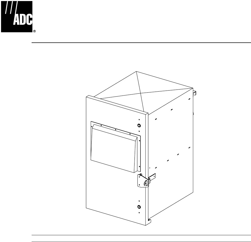
1 DESCRIPTION
The Digivance LRCS Single Band SMR Remote Unit (RU), serves as the cellular user servicing
unit for the Digivance LRCS Single Band SMR system. The system consists of up to 15 Host
Units (HUs) each of which is attached to asingle RU. In the forward direction, the RU receives
digital optical signals from the HU, converts the digital optical signals into an RF signal format,
and transmits these signals to cellular phones. In the reverse path, the RU receives RF signals
from cellular phones, digitizes the RF signals, converts the signals to digital optical format, and
transmits the signals to the HU. RUs configured with the Diversity option require aredundant
fiber optic reverse path to the HU. All RUs are configured with aminimum of one antenna to
transmit and receive RF signal transmissions between the RU and the cellular phones. On RUs
configured with the Diversity option, asecond antenna is connected to the RU to provide a
redundant receive RF signal path from the cellular phones. The RU also transports alarm status
to and from the HU using the optical link.
2 UNPACKING AND INSPECTION
After receiving the components of the RU, unwrap each item and inspect for damage or missing
parts. The basic RU components package includes the following items:
•SpectrumTransport Module (STM)
•LinearPower Amplifier (LPA) Module
Danger: Danger is used to indicate the presence of ahazard that will cause severe personal
injury, death, or substantial property damage if the hazard is not avoided.
Warning: Warning is used to indicate the presence of ahazard that can cause severe personal
injury, death, or substantial property damage if the hazard is not avoided.
Caution: Caution is used to indicate the presence of ahazard that will or can cause minor
personal injury or property damage if the hazard is not avoided.
Warning: This equipment generates, uses, and can radiate radio frequency energy and if not
installed and used in accordance with the instruction manual, may cause interference to radio co
ADCP-75-115 • Issue A • August 2001
Page 5
©2001, ADC Telecommunications, Inc.
The following optional components may also be shipped with the basic component package:
•BatteryBackup Kit
•WaveDivision Multiplexer (WDM) Kit
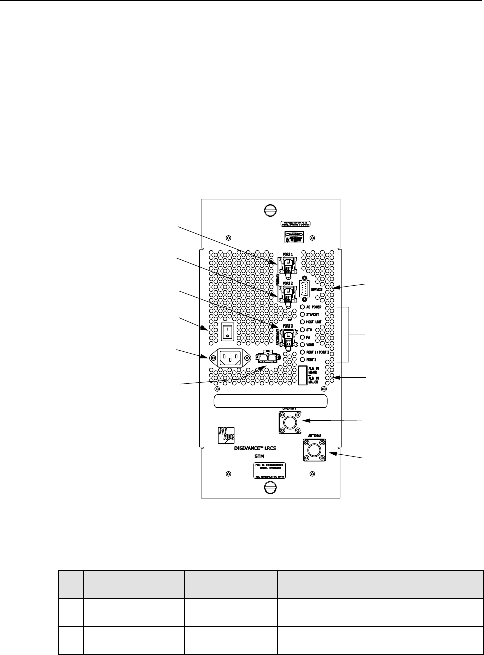
3 STM USER INTERFACE
The STM user interface consists of the various connectors, switches, and LEDs that are
provided on the STM front panel. The STM user interface points are indicated in Figure 1 and
described in Table 2.
Figure 1. Spectrum Transport Module User Interface
Table 2. Spectrum Transport Module User Interface
REF
NO USER INTERFACE
DESIGNATION DEVICE FUNCTIONAL
DESCRIPTION
1PORT1SCconnector Connection point for the forward path fiber optic
link.
2PORT2SCconnector Connection point for the reverse path primary
fiber optic link.
16801-A
(4) ON/OFF
SWITCH
(5) AC POWER
CONNECTOR
(6) DC POWER
CONNECTOR
(1) PORT 1
CONNECTOR
(2) PORT 2
CONNECTOR
(3) PORT 3
CONNECTOR (7) SERVICE
CONNECTOR
(8-15) LED
INDICATORS
(16) ALARM
CONNECTOR
(17) DIVERSITY
ANTENNA
CONNECTOR
(18) ANTENNA
CONNECTOR

ADCP-75-115 • Issue A • August 2001
Page 6
©2001, ADC Telecommunications, Inc.
3PORT3
(diversity unit only)
SC connector Connection point for the reverse path diversity
fiber optic link.
4I/O On/Offrocker
switch Provides AC power on/off control.
5Nodesignation 3-wire AC power
cord connector Connection point for the AC power cord.
6Nodesignation 2- wire DC power
cord connector Connection point for the battery back-up power
cord.
7 SERVICE DB-9 connector
(female) Connection point for the RS-232 service inter-
face cable.
8ACPOWER Multi-colored LED
(green/yellow)
Indicates if the STM is powered by the AC power
source (green) or the battery back-up system
(red). See Note.
9 STANDBY Multi-colored LED
(green/yellow)
Indicates if the system is in the Normal state (off)
Standby state (blinking green), Test state (blink-
ing red), or Program Load state (blinking yel-
low). See Note.
10 HOST UNIT Multi-colored LED
(green/yellow/red)
Indicates if the HU is normal (green) or faulty
(red). See Note.
11 STM Multi-colored LED
(green/yellow/red)
Indicates if the STM is normal (green) or faulty
(red). See Note.
12 PA Multi-colored LED
(green/yellow/red)
Indicates if the power amplifier is normal
(green), over temperature (yellow), has afan fail-
ure (yellow), or is faulty (red). See Note.
13 VSWR Multi-colored LED
(green/yellow/red)
Indicates if the forward path VSWR is above
(red) or below (green) the fault threshold.
14 PORT 1/PORT 2 Multi-colored LED
(green/yellow/red)
Indicates if the forward path optical signal
received from the HU is normal (green), if no sig-
nal is detected (red), or if errors are detected
(red). See Note.
15 PORT 3
(diversity unit only)
Multi-colored LED
(green/yellow/red)
Indicates if the diversity reverse path optical sig-
nal received by theHU is normal (green), if no
signal is detected (red), or if errors are detected
(red). See Note.
16 ALARM IN MINOR
ALARM IN MAJOR
Screw-type terminal
connector (14–26
AWG)
Connection point for two external alarm inputs.
The door-open switch lead wires are typically
connected to the major alarm terminals.
17 DIVERSITY
(diversity unit only)
N-type female RF
coaxial connector Connection point for the diversity antenna.
18 ANTENNA N-type female RF
coaxial connector Connection point for the primary antenna.
Note: Amore detailed description of LED operation is provided in the Digivance LRCS Single Band
SMR Installation and Operation Manual (ADCP-75-116).
Table 2. Spectrum Transport Module User Interface, continued
REF
NO USER INTERFACE
DESIGNATION DEVICE FUNCTIONAL
DESCRIPTION
ADCP-75-115 • Issue A • August 2001
Page 7
©2001, ADC Telecommunications, Inc.
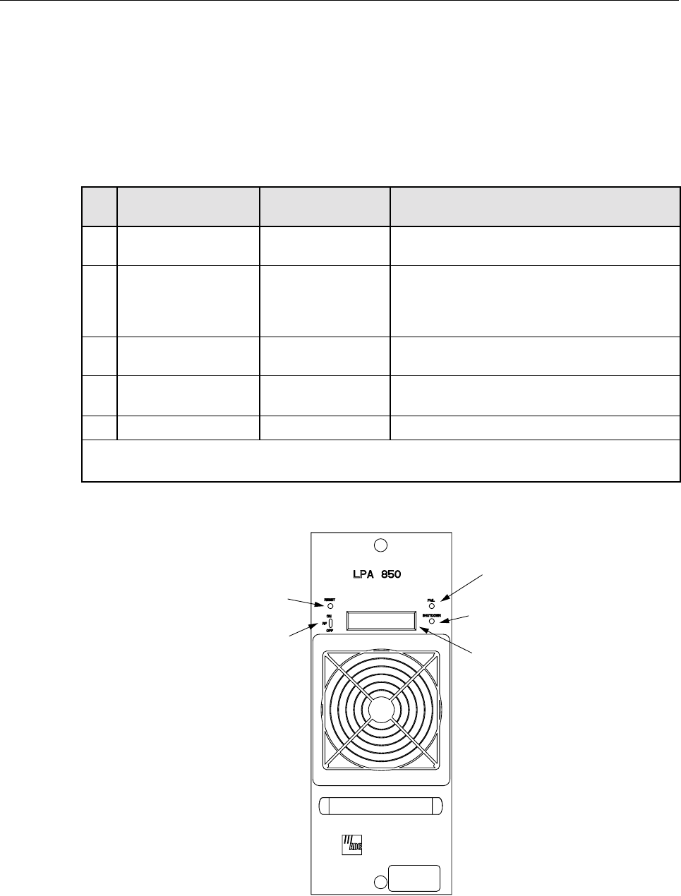
4 LPA USER INTERFACE
The LPA user interface consists of the various LEDs, message displays, and switches that are
provided on the LPA front panel. The LPA user interface points are described in Table 3 and
indicated in Figure 2.
Figure 2. Linear Power Amplifier User Interface
Table 3. Linear Power Amplifier User Interface
REF
NO USER INTERFACE
DESIGNATION DEVICE FUNCTIONAL
DESCRIPTION
1 RESET Momentary contact
push button switch Momentarily pressing the switch push button
clears all alarms and restarts the amplifier
2RFON OFF 2-position switch Placing the switch in the OFF position puts the
LPA in astandby state with RF output disabled.
Placing the switch in the ON position puts the
LPA in the normal state with RF output enabled.
3FAIL LEDindicator
(yellow) Indicates the LPA is normal (off) or faulty
(yellow).
4 SHUTDOWN LED indicator (red) Indicates the LPA is in service (off) or shutdown
(red).
5Nodesignation Digital display Provides status and alarm messages. See Note.
Note: Amore detailed description of the digital display messages is provided in the Digivance LRCS
Single Band SMR Installation and Operation Manual (ADCP-75-116).
(1) RESET
SWITCH
(2) RF ON/OFF
SWITCH
(3) FAIL
LED
(4) SHUTDOWN
LED
(5) DIGITAL
DISPLAY
16804-A

ADCP-75-115 • Issue A • August 2001
Page 8
©2001, ADC Telecommunications, Inc.
5 WDM USER INTERFACE
The WDM user interface consists of aconnector and two trailing cables provided on the WDM
front panel. The WDM user interface connectors are described in Table 4 and indicated in
Figure 2.
Figure 3. WDM User Interface
6 INSTALLATION PROCEDURES
This section provides installation instructions for the STM and LPA modules, the battery
backup option and the WDM option. Use the ADC-provided 7/16-inch nut driver taped to the
outside of the cabinet to open the door latches and gain access to the interior of the cabinet.
6.1 STM Module
Perform the following steps to install the Spectrum Transport Module (STM):
1. Check to ensure that the PWR ON/OFF switch on the STM is set to OFF (refer to item 4
on Figure 1).
Table 4. Wave Division Multiplexer (WDM) User Interface
REF
NO USER INTERFACE
DESIGNATION DEVICE FUNCTIONAL
DESCRIPTION
1WDM SCConnector Connection point for the bi-directional indoor/
outdoor cable from the splice tray enclosure.
2 OUT Cable with SC Con-
nector Connection point for the forward path trailing
cable to the PORT 1connector on the STM.
3IN Cablewith SC Con-
nector Connection point for the reverse path trailing
cable to the PORT 2connector on the STM.
Drawing not available
ADCP-75-115 • Issue A • August 2001
Page 9
©2001, ADC Telecommunications, Inc.
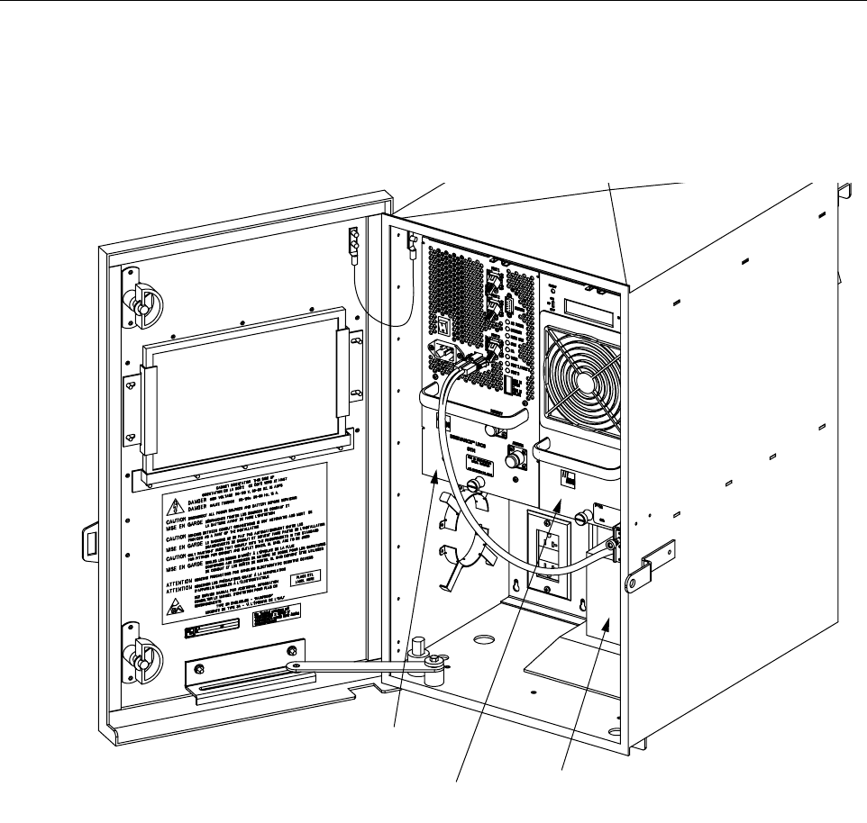
2. Gently slide the STM into the cabinet at the location shown in Figure 4.If resistance is
encountered, remove the STM and check the alignment of the mating connector on the
backplane.
3. Tighten the two compression screws that secure the STM to the cabinet mounting shelf.
Figure 4. Installing RU Components
6.2 LPA Module
perform the following steps to install the Linear Power Amplifier (LPA):
1. Check to ensure that the RF ON/OFF switch on the LPA is set to OFF (refer to item 2on
Figure 2).
2. Gently slide the LPA into the cabinet at the location shown in Figure 4.If resistance is
encountered, remove the LPA and check the alignment of the mating connector on the
backplane.
3. Tighten the two compression lock screws that secure the LPA the cabinet mounting shelf.
16813-A
SPECTRUM
TRANSPORT
MODULE (STM)
LINEAR POWER
AMPLIFIER (LPA)
BATTERY
BACKUP
(OPTIONAL)

ADCP-75-115 • Issue A • August 2001
Page 10
©2001, ADC Telecommunications, Inc.
6.3 Battery Backup Kit Installation (Optional)
Perform the following steps to install the optional battery pack:
1. Slide the battery pack into position on the heated tray within the cabinet as shown in
Figure 4.
2. Route the trailing battery cable from the battery pack to the battery connector on the front
of the STM (refer to item 6on Figure 1).
Refer to the Digivance LRCS Single Band Installation and Operation Manual (ADCP-75-116)
for adescription of the monthly, semi-annual, and biennial maintenance procedures for the
battery pack.
6.4 WDM Installation (Optional)
Perform the following steps to install the WDM:
1. Slide the WDM into position underneath the cabinet mounting shelf as shown in Figure 4.
2. Use the four 6 x 24 mounting screws and washers provided with the WDM to secure the
WDM to the underside of the mounting shelf.
7CABLING
There are three cable types that must be installed as part of RU installation: power, fiber optic,
and coaxial. The power cables are routed between the RU and an AC power breaker box. The
fiber optic cables are routed between the HU and the RU. The coaxial cables are routed between
the antenna(s) and the RU.
7.1 AC Power Wiring
Adedicated customer-provided external breaker box supplying 120 Vac, 50/60 Hz, 20 Amp,
single-phase, AC power is required to operate the components in the cabinet. The RU is pre-
Caution: The battery pack weighs approximately 75 lb (34 kg). Enlist sufficient aid to lift the
battery pack into position inside the cabinet.
Danger: The RU power circuits are High Voltage. Use extreme caution. Ensure all power is
disconnected before working on power circuits.
Caution: For proper equipment operation agood earth ground or water pipe ground
connection must be provided. The recommended minimum wire size for use is #6 AWG wire.
Note: All electrical work must comply with Local Codes. Alocal licensed electrical
contractor is best qualified to perform this work.
ADCP-75-115 • Issue A • August 2001
Page 11
©2001, ADC Telecommunications, Inc.
wired for 120 Vac but can be converted to 240 Vac operation through the installation of a240
Vac outlet kit (accessory item). Connect the AC power wiring as follows:
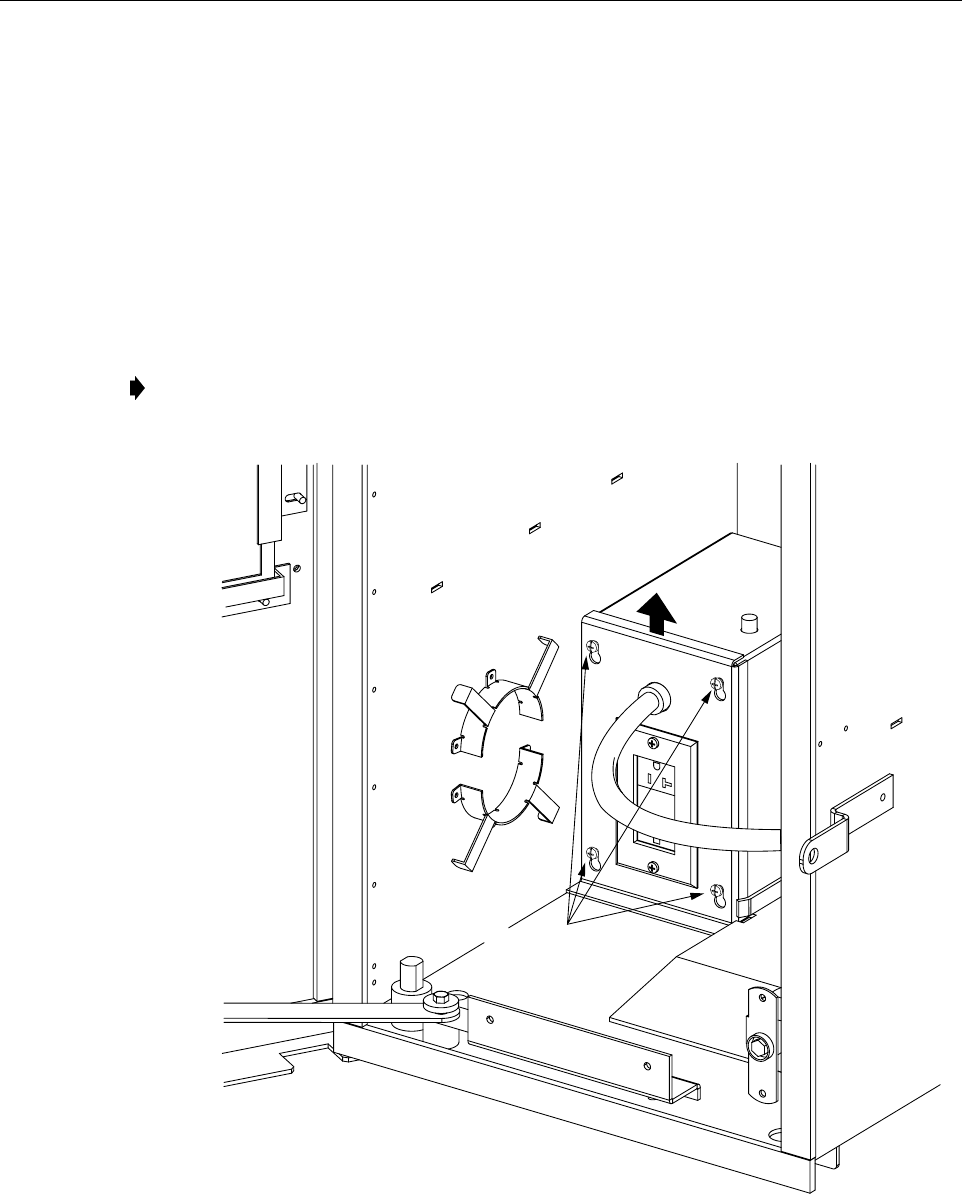
1. Obtain access to the internal power wiring harness inside the auxilary junction box by
loosening the four screws securing the auxiliary box cover, pulling up and removing the
cover. see Figure 5.
2. Route the external AC power conduit to the AC power 3/4-inch NPT threaded hole on the
left-rear underside of the cabinet directly underneath the auxiliary junction box. See
Figure 6.Use the conduit fitting provided, or aUL approved equivalent, to provide a
moisture barrier. The 3/4-inch (19.0 mm) conduit fitting mounted on the underside of the
cabinet is designed to accept threaded rigid conduit.
Figure 5. Accessing AC Power Wiring
Note: A3/4-inch to 1/2-inch (12.7 mm) reducer fitting is provided to accommodate 1/2-
inch threaded conduit.
16788-A
LOOSEN FOUR
SCREWS AND
LIFT TO REMOVE
COVER
ADCP-75-115 • Issue A • August 2001
Page 12
©2001, ADC Telecommunications, Inc.
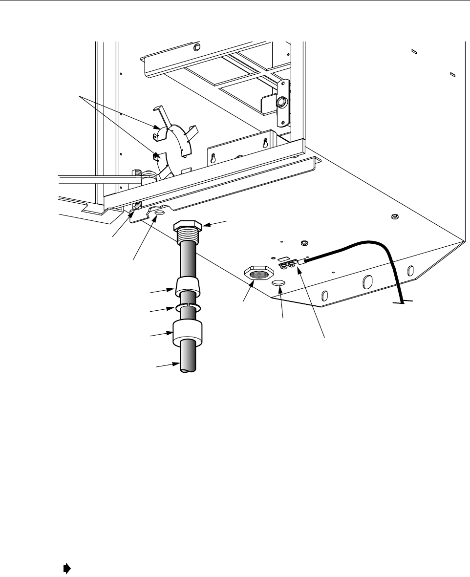
Figure 6. Cable Entry Ports on Cabinet
3. A grounding lug is provided on the underside of the cabinet. Connect aground wire to
this lug as required to meet local codes.
4. Attach the white (neutral), green (ground) and black (hot) wires from the internal AC
harness coiled up inside the junction box to the corresponding conductors in the external
conduit using the twist-lock fasteners provided.
5. Re-position the auxilary junction box cover on the front of the junction box and tighten the
four screws securing the cover.
6. Connect the power cord trailing from the cover of the auxiliary junction box to the AC
connector on the front of the STM (refer to item 5on Figure 1).
Note: The duplex Ground Fault Circuit Interrupter (GFIC) outlet provided on the cover of
the auxiliary junction box is wired to accept 120 Vac appliances. If the cabinet is re-wired
for 240 Vac, the 120 Vac outlet must be replaced.
BUSHING
SPLIT
RING
COMPRESSION
NUT
INDOOR/
OUTDOOR
CABLE
16790-A
TO APPROVED
GROUND
SOURCE
CABINET
GROUND
LUG
DRAIN
HOLE
AC
SUPPLY
PORT
FIBER PORT
(HUBBELL
CONNECTOR
BODY)
DIVERSITY
ANTENNA PORT
PRIMARY
ANTENNA
CABLE
STORAGE
SPOOLS

ADCP-75-115 • Issue A • August 2001
Page 13
©2001, ADC Telecommunications, Inc.
7.2 Routing Pre-Connectorized Indoor/Outdoor Fiber Optic Cable
Fiber optic cable termination typically consists of routing apre-connectorized indoor/outdoor
fiber optic cable between the cabinet and an external splice tray enclosure, securing the cable to
the cabinet, breaking out the individual jacketed pigtail fibers inside the cabinet, and connecting
the fibers to the WDM (optional) or STM.
Cable storage spools is provided on the interior wall of the cabinet to accumulate excess indoor/
outdoor cable length and also serve as along-term storage location for redundant cable. All
fiber optic cable connections within the RU require SC cable connectors.
7.2.1 Terminating the Indoor/Outdoor Cable(WDM Feature Not Installed)
Use the following procedure to terminate the individual pigtails in the indoor/outdoor cable:
1. Insert an appropriate sized compression fitting into the water-resistant connector installed
on the bottom of the cabinet (see Figure 6).
2. Route the stub end of the pre-connectorized indoor/outdoor cable down throuth the water-
resistant connector to the external splice tray enclosure.
3. Tighten the compression fitting on the cable port to secure the cable.
4. Strip back the outer sheathing of the customer-provided indoor/outdoor cable inside the
cabinet to allow the connectorized individual jacketed pigtails to be routed to the STM or
cabinet storage spools.
a. Connect the forward path fiber to the PORT 1SC connector on the STM (refer to item
1on Figure 1).
b. Connect the reverse path fiber to the PORT 2SC connector on the STM (refer to item
2on Figure 1).
c. On units with the Diversity feature, connect the secondary reverse path fiber to the
PORT 3SC connector on the STM (refer to item 3on Figure 1).
5. Coil up the excess cable length on the cabinet cable storage spools.
7.2.2 Terminating the Indoor/Outdoor Cable (WDM Feature Installed)
Use the following procedure to terminate the individual pigtails in the indoor/outdoor cable:
Note: The routing of an OSP fiber optic cable from the HU to asplice tray enclosure in the
vicinity of the RU and the splicing of selected OSP cable fibers to fibers in the indoor/
outdoor cable is the responsibility of the customer.
Warning: To avoid exposure to to invisible laser radiation, do not look into the ends of any
optical fiber or bulkhead connector. Never assume laser power is turned off or that the fiber is
disconnected at the other end. Use an optical power meter to identify active fibers. Always
place aprotective cap over any unused bulkhead connector or optical fiber connector.

ADCP-75-115 • Issue A • August 2001
Page 14
©2001, ADC Telecommunications, Inc.
1. Insert an appropriate sized compression fitting into the water-resistant connector installed
on the bottom of the cabinet (see Figure 7).
2. Route the stub end of the pre-connectorized indoor/outdoor pigtail down throuth the
water-resistant connector to the external splice tray enclosure.
3. Tighten the compression fitting on the cable port to secure the cable.
4. Strip back the outer sheathing of the customer-provided indoor/outdoor pigtail inside the
cabinet to allow the connectorized individual jacketed fibers to be routed to the WDM or
cabinet storage spools.
a. Connect the bi-directional pigtail fiber to the WDM SC connector on the WDM (see
Figure 7).
b. On units with the Diversity feature, connect the secondary reverse path pigtail fiber
directly to the PORT 3SC connector on the STM (refer to item 3on Figure 1).
5. Coil up the excess cable length on the cabinet cable storage spools.
6. Refer to Subsection 7.4, Terminating WDM Forward and Reverse Cables for information
on routing and terminating the WDM Forward and Reverse jumper cables.
Figure 7. Terminating Indoor/Outdoor Pigtail (WDM Option Installed)
7.3 Antenna Cables
Acustomer supplied coaxial antenna cable must be routed from each antenna and attached to a
lightning protector mounted on the underside of the cabinet (see Figure 6). The cable must be
connectorized with an N-type connector for attachment to the to the underside of the lightning
protector. ADC-provided coaxial jumper cables configured with N-type connectors on both
ends are used to route RF from the top of each lightning protector to connectors on the STM.
Each cabinet is shipped to the field configured with one lightning protector (primary), and one
coaxial RF jumper cable that must be attached to the Antenna connector on the STM (refer to
item 18 on Figure 1). Asecond lightning protector and RF jumper cable is provided in the
Warning: To avoid exposure to to invisible laser radiation, do not look into the ends of any
optical fiber or bulkhead connector. Never assume laser power is turned off or that the fiber is
disconnected at the other end. Use an optical power meter to identify active fibers. Always
place aprotective cap over any unused bulkhead connector or optical fiber connector.
Drawing not available

ADCP-75-115 • Issue A • August 2001
Page 15
©2001, ADC Telecommunications, Inc.
Diversity Cable kit. The Diversity jumper cable must be attached to the Diversity connector on
the STM (refer to item 17 on Figure 1).
7.4 Terminating WDM Forward and Reverse Cables
Use the following procedure to terminate the WDM forward and reverse cables :
1. Connect the 1-meter trailing FORWARD cable (Figure 8)from the WDM to the PORT 1
SC connector on the STM (refer to item 1on Figure 1).
2. Connect the 1-meter trailing REVERSE cable (Figure 8)from the WDM to the PORT 2
SC connector on the STM (refer to item 2on Figure 1).
3. Attaching the indoor/outdoor cable to the WDM connector is decribed in Subsection 7.2.2,
Terminating the Indoor/Outdoor Cable (WDM Feature Installed) .
4. Coil up the excess cable length on the cabinet cable storage spools.
Figure 8. Terminating WDM Forward and Reverse Cables
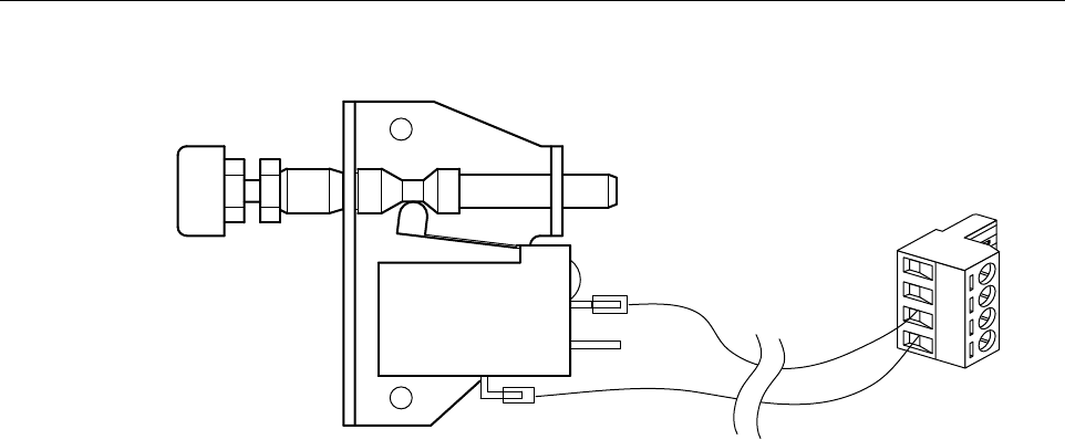
8 CONNECTORIZING THE DOOR OPEN SWITCH
The door open switch is shipped to the field with stubbed power conductors. Install the stubbed
conductors from the door open switch in the ADC-provided right angle plug at the pin locations
shown in Figure 9.After completing this step, insert the right angle connector into the alarm
connector on the front of the STM (refer to item 16 on Figure 1). Adoor open condition
typically generates aMajor Alarm.
Note: To comply with Maximum Permissible Exposure (MPE) requirements, the
maximum composite output from the antenna cannot exceed 1000 Watts EIRP and the
antenna must be permanently installed in afixed location that provides at least 6meters
(20 feet) of separation from all persons.
Warning: To avoid exposure to to invisible laser radiation, do not look into the ends of any
optical fiber or bulkhead connector. Never assume laser power is turned off or that the fiber is
disconnected at the other end. Use an optical power meter to identify active fibers. Always
place aprotective cap over any unused bulkhead connector or optical fiber connector.
Drawing not available
ADCP-75-115 • Issue A • August 2001
Page 16
©2001, ADC Telecommunications, Inc.
Figure 9. Connectorizing Door Open Switch
9 FINAL TEST AND ADJUSTMENTS
When the installation is completed, refer to the Digivance Single Band LRCS Installation and
Operation Manual (ADCP-75-116) for system turn-up and test procedures.
This section under construction
16791-A

ADCP-75-115 • Issue A • August 2001
Page 17
©2001, ADC Telecommunications, Inc.
10 CUSTOMER INFORMATION AND ASSISTANCE
For customers wanting information on ADC products or help in using them, ADC offers the
services listed below. To obtain any of these services by telephone, first dial the central ADC
telephone number, then dial the extension provided below.
The central number for calls originating in the U.S.A. or Canada is 1-800-366-3891.For calls
originating outside the U.S.A. or Canada, dial country code “1” then dial 952-946-3000.
Product information may also be obtained using the ADC web site at www.adc.com or by
writing ADC Telecommunications, Inc., P.O. Box 1101, Minneapolis, MN 55440-1101, U.S.A.
Contents herein are current as of the date of publication. ADC reserves the right to change the contents without prior notice. In no
event shall ADC be liable for any damages resulting from loss of data, loss of use, or loss of profits and ADC further
disclaims any and all liability for indirect, incidental, special, consequential or other similar damages. This disclaimer of
liability applies to all products, publications and services during and after the warranty period.
This publication may be verified at any time by contacting ADC’s Technical Assistance Center at 1-800-366-3891, extension 63475
(in U.S.A. or Canada) or 952-946-3475 (outside U.S.A. and Canada), or by e-mail to bcg_tac@adc.com.
©2001, ADC Telecommunications, Inc.
All Rights Reserved
Printed in U.S.A .
Sales Assistance
Extension 63000 • Quotation Proposals
•Orderingand Delivery
• General Product Information
Systems Integration
Extension 63000 • Complete Solutions (from Concept to Installation)
•NetworkDesign and Integration Testing
•SystemTurn-Up and Testing
•NetworkMonitoring (Upstream or Downstream)
•PowerMonitoring and Remote Surveillance
• Service/Maintenance Agreements
•SystemsOperation
BCG Technical Assistance Center
Extension 63475
E-Mail: bcg_tac@adc.com
• Technical Information
•System/NetworkConfiguration
• Product Specification and Application
•Training(Product-Specific)
• Installation and Operation Assistance
• Troubleshooting and Repair
Product Return Department
Extension 63748
E-Mail: repair&return@adc.com
•ADCReturn Authorization number and instructions
must be obtained before returning products.