ASSALOY SCYPROX3 Microprocessor Controlled Networked Locks User Manual XX XXXX Exhibit Cover
ASSA ABLOY Inc. Microprocessor Controlled Networked Locks XX XXXX Exhibit Cover
ASSALOY >
Contents
- 1. Manual 1 of 3
- 2. Manual 2 of 3
- 3. Manual 3 of 3
Manual 1 of 3
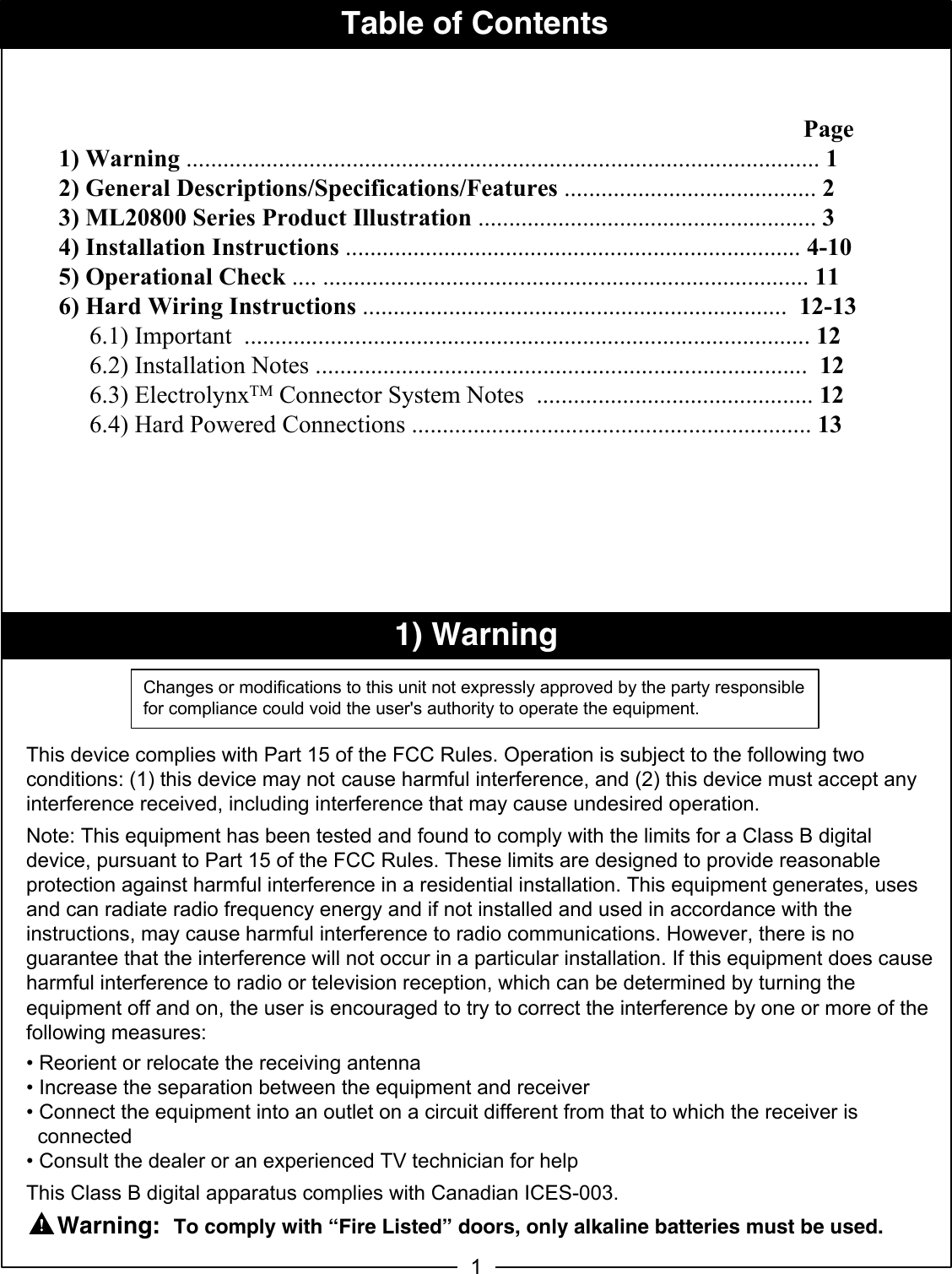
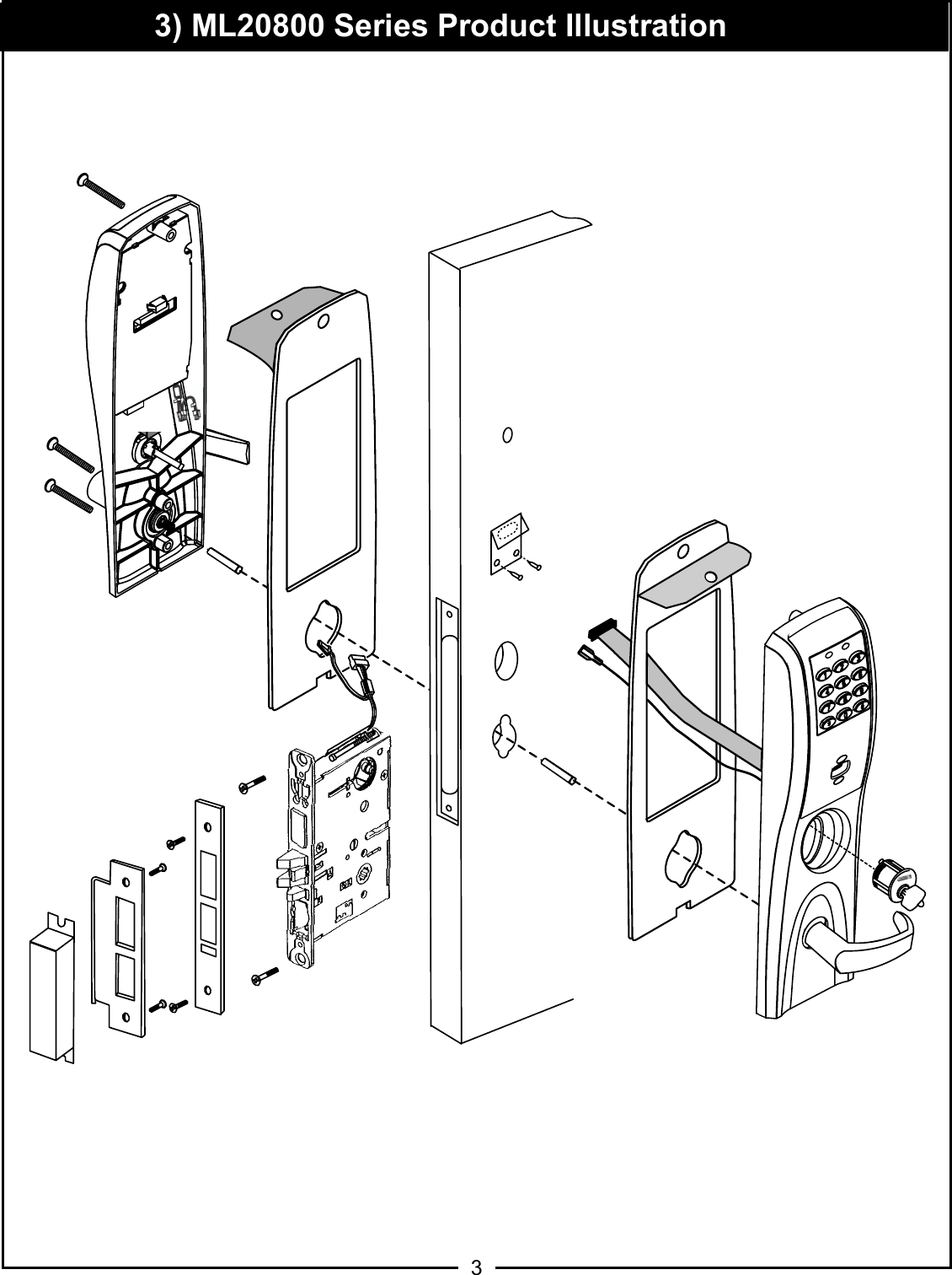
![2 General Description The Corbin Russwin Access 800 TCWI1 0RUWLVH Lock is designed for applications requiring wireless access control. The TCWI1 is a self-contained microprocessor-controlled access control product with non-volatile memory. It is able to utilize the existing wireless LAN 802.11 b/g in order to communicate with the access control system. The TCWI1 lock will hold a total of 2000 different user codes. This product is operated by six (6) "AA" alkaline batteries or by Corbin Russwin 784 9VDC power supply. Corbin Russwin 0RUWLVH locks are designed with quality components to provide high security, performance and durability. Specifications • Latch 6WDLQOHVV6WHHO • /RFNLQJVLGHFRQWUROOHGE\DQ\FRPELQDWLRQ RINH\SDGSUR[FDUGRUF\OLQGHURYHUULGH • 1RQORFNLQJVLGHOHYHUUHWUDFWVODWFKDQG • 'HDGEROW6WDLQOHVV6WHHO GHDGEROW• $X[LOLDU\/DWFK6WDLQOHVV6WHHOQRQKDQGHG• +DQGLQJ(DVLO\ILHOGUHYHUVLEOHZLWKRXWGLVDVVHPEOLQJWKHORFNERG\/RFNVIXUQLVKHGIRUGRRUV&DQEH&DVHJDXJHKHDY\GXW\ZURXJKWVWHHOIXUQLVKHGIRURWKHUGRRUVL]HVXSRQUHTXHVW8//LVWHGKU&RQVXOW)DFWRU\ Features • WiFi 802.11 b/g enabled • 2000 Users per lock (more possible with software) • 10,000 Event audit trail • Centralized lock management• Real Time Door Status Monitoring (Only applies when unit is hard powered) • Easy Installation • HID Prox Compatible (125kHz 26-39 Bit) 2) General Descriptions/ Specifications/ Features](https://usermanual.wiki/ASSALOY/SCYPROX3.Manual-1-of-3/User-Guide-1434414-Page-4.png)