ASSALOY SCYPROX3 Microprocessor Controlled Networked Locks User Manual XX XXXX Exhibit Cover
ASSA ABLOY Inc. Microprocessor Controlled Networked Locks XX XXXX Exhibit Cover
ASSALOY >
Contents
- 1. Manual 1 of 3
- 2. Manual 2 of 3
- 3. Manual 3 of 3
Manual 2 of 3

5015 B.U. Bowman Drive Buford, GA 30518 USA Voice: 770-831-8048 Fax: 770-831-8598
Certification Exhibit
FCC ID: U4A-SCYPROX3
IC: 6982A-SCYPROX3
FCC Rule Part: 15.209
IC Radio Standards Specification: RSS-210
ACS Report Number: 10-0443.W06.11.A
Manufacturer: Assa Abloy
Model: S1-PA/PK, S2-PA/PK,
TCIP1-M802/M803, TCWI1-M802/M803
Manual(s)
A7764B
01/11
Copyright 2011, Sargent Manufacturing Company, an ASSA ABLOY Group company.
All rights reserved. Reproduction in whole or in part without the express written
permission of Sargent Manufacturing Company is prohibited.
Profile
PoE Mortise Lock
Installation Instructions
v.S1
1-800-810-WIRE • www.sargentlock.com • A7764B
Copyright © 2011, Sargent Manufacturing Company, an ASSA ABLOY Group company. All rights reserved.
Reproductions in whole or in part without express written permission of Sargent Manufacturing Company is prohibited.
01/29/11
1
2
3
4
5
6
7
Table of Contents
Warning ...................................................................................2
General Description .................................................................3
Hardware Specifications .........................................................3
Electronic Specifications .........................................................3
Installation Wiring Overview ...................................................3
Installation Wiring ...................................................................4
Parts Breakdown .....................................................................8
Lock Installation ....................................................................10
Operational Check ................................................................17
8
9
Changes or modifications to this unit not expressly approved by ASSA ABLOY Inc.
could void the user’s authority to operate the equipment.
1Warning
Warning SARGENT Mfg. Co. v.S Series locksets utilizing a door position switch (DPS) are not rated for,
or intended for use in life safety applications.
!
FCC:
This equipment has been tested and found to comply with the limits for a Class A digital device, pursuant to part 15 of
the FCC rules. These limits are designed to provide reasonable protection against harmful interference when the equip-
ment is operated in a commercial environment. This equipment generates, uses, and can radiate radio frequency energy
and, if not installed and used in accordance with the instruction manual, may cause harmful interference to radio com-
munications. Operation of this equipment in a residential area is likely to cause harmful interference in which case the
user will be required to correct the interference at his own expense.
Industry Canada:
The term “IC:” before the radio certification number only signifies that Industry Canada technical specifications were
met.
This Class A digital apparatus meets all requirements of the Canadian Interference Causing Equipment Regulations. Op-
eration is subject to the following two conditions: (1) this device may not cause harmful interference, and (2) this device
must accept any interference received, including interference that may cause undesired operation.
Cet appareillage numérique de la classe A répond à toutes les exigences de l’interférence canadienne causant des
règlements d’équipement. L’opération est sujette aux deux conditions suivantes: (1) ce dispositif peut ne pas causer
l’interférence nocive, et (2) ce dispositif doit accepter n’importe quelle interférence reçue, y compris l’interférence qui
peut causer l’opération peu désirée.
01/29/11
1-800-810-WIRE • www.sargentlock.com • A7764B 3
Copyright © 2011, Sargent Manufacturing Company, an ASSA ABLOY Group company. All rights reserved.
Reproductions in whole or in part without express written permission of Sargent Manufacturing Company is prohibited.
Profile Series v.S1 PoE Mortise Lock
General Description
The SARGENT Profile Series v.S1 Mortise Lock is available with either an HID® 125 kHz prox or 13.56 MHz
iCLASS® technology reader. It utilizes existing infrastructure and IEEE 802.3af PoE (Power over Ethernet)
technology as a proven alternative to traditional access control installations.The v.S1 is a self-contained
microprocessor-controlled access control product with non-volatile memory. It uses the existing network
cable to communicate with access control systems. The v.S1 lock holds a total of 2400 unique users per lock.
Using PoE technology coupled with approved third party software, this v.S1 online lock offers a complete,
integrated access control system.
The Profile Series v.S1 Mortise lock may be used for both indoor and exterior applications.
A weather-protective gasket is recommended for exterior applications.
HID and iCLASS are registered trademarks of HID Global Corporation.
Hardware Specifications
3Electronic Specifications
4
2
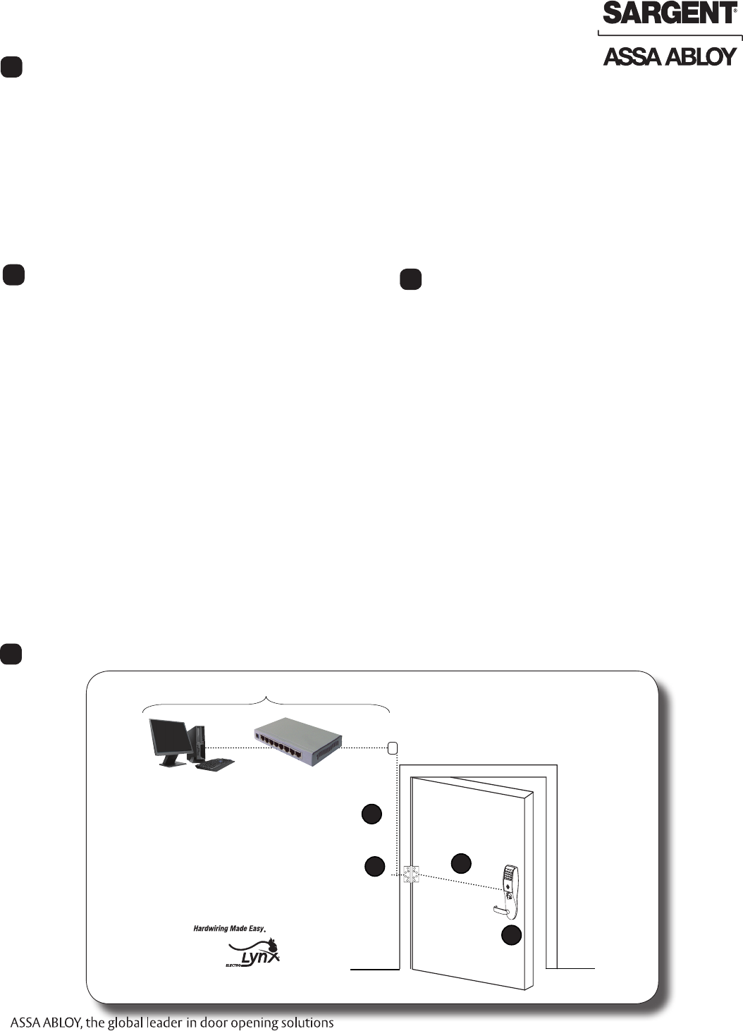
Installation Wiring Overview
5
• 2400 users per lock; 10,000 event audit trail
• Multiple time zone and holiday
access scheduling
• Centralized lock management
• Real time door status monitoring
• First-In unlock configuration, either by time
or by user (selectable)
• Lock down capable
• Input Power: PoE Class 2 Device, as defined
by IEEE 802.3af
• Supports HID® 125 kHz prox or 13.56 MHz
iCLASS® credentials (26 - 39 bit); supports
CSN reads for other common 13.56 MHz
cards, including MiFare, DesFire, and Felica
• Complete lockset with on-board memory
• Available with or without keypad
• ADA compliant
• Latch: One-piece stainless steel, 3⁄4"projection
• Deadbolt: One-piece hardened stainless steel
• Guardbolt: Stainless steel, non-handed
• Case - 12 gauge, heavy duty, wrought steel
• Inside lever retracts latch and deadbolt
• UL Listed (3 hr.)
• Handing (RH/LH/RHR/LHR) can be specified
but is easily field-reversible without
disassembling the lock body
• Locks furnished for 1-3/4” doors. Can be fur-
nished for other door sizes upon request. Con-
sult factory.
• Wire from EAC Panel to door must be shielded
with drain terminated at EAC Panel controller
Supplied by Others
A. PoE Frame harness assembly
B. PoE data hinge from McKinney
(patent pending)
C. PoE Door harness* from McKinney
D. Profile Series S1 PoE Lock
* Door width determines length
Network
Cable
Network Switch (802.3af)
A
BC
D
Surface Mount RJ45
4 1-800-810-WIRE • www.sargentlock.com • A7764B
Copyright © 2011, Sargent Manufacturing Company, an ASSA ABLOY Group company. All rights reserved.
Reproductions in whole or in part without express written permission of Sargent Manufacturing Company is prohibited.
01/29/11
Profile Series v.S1 PoE Mortise Lock
PoE frame harness assembly (From McKinney)
PoE data hinge (Patent Pending) (From McKinney)
PoE door harness* (From McKinney)
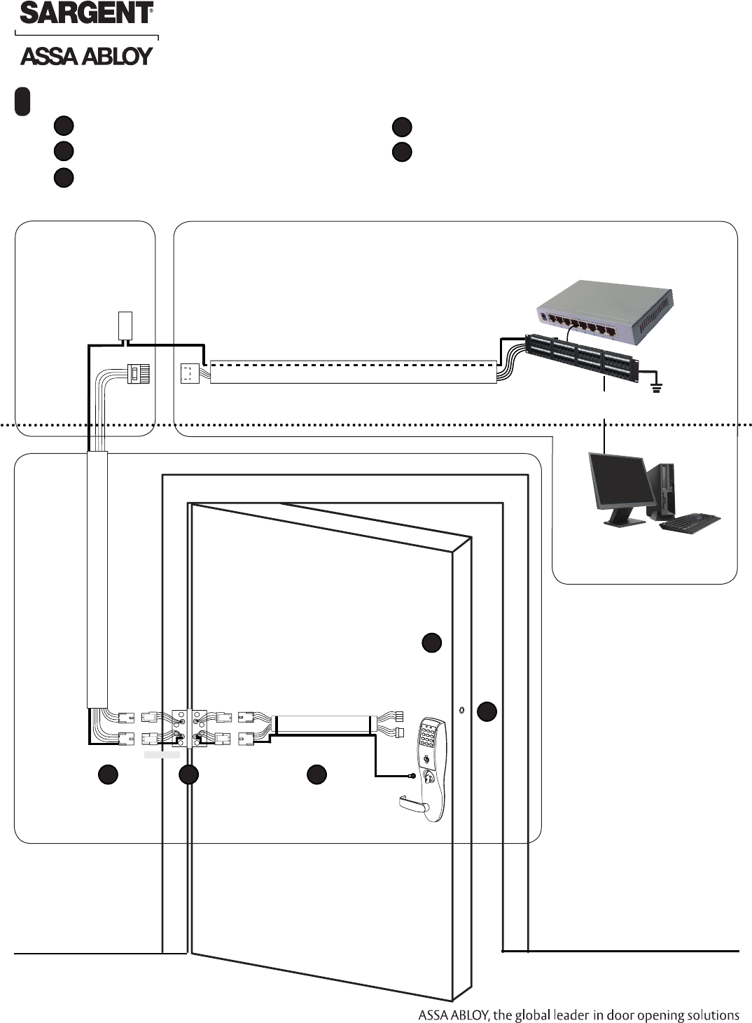
6Installation Wiring
Cable: CAT 5e or higher
24 AWG shielded with drain wire
4-Pin
Molex-F Molex-F Molex-M
Cable: CAT 5e,
26 AWG stranded,
shielded, 100ohm
Wiring to TIA-568-B Standard
RJ45-M
Molex-M
RJ45-F Jack
Cable: CAT 5e or higher
24 AWG shielded, 100ohm
Approved Software
B-Splice
Crimp Connector
Certified Integrator (CI) supplies and terminates
the B-Splice connector and the
Male RJ45 connector from harness to
end user provided facility cable
Supplied by End User
PoE Switch
PoE
Lock
Ceiling
Supplied by CI
Patch Panel
Drain Wire Terminated on Rack
Ground
Ring Terminal
Secured to Lock
Mounting Plate
Drain Wire PoE Switch
Terminated to
Earth Ground
Patch Cable:
Patch Panel to
PoE Switch
4-Pin
DPS: Door Position Switch (cylindrical and exits only)
Profile Series v.S1 Online P1 PoE lock
* Order of installation may vary.
Refer to appropriate sections for instructions.
Frame-
Side
Harness
Assembly
(15' length)
24AWG
Stranded
Wire for
Earth
Ground
inside
15' Frame
Harness
Cable
drain wire
concealed
in shrink
tubing
A
E
D
C
A B
E
D
C
Notes:
• Connectors go on
only one way. They
cannot placed in an
incorrect position.
• Do not force and do
not offset connec-
tors.
• Be sure they are
completely seated
(flush).
B
01/29/11
1-800-810-WIRE • www.sargentlock.com • A7764B 5
Copyright © 2011, Sargent Manufacturing Company, an ASSA ABLOY Group company. All rights reserved.
Reproductions in whole or in part without express written permission of Sargent Manufacturing Company is prohibited.
Profile Series v.S1 PoE Mortise Lock
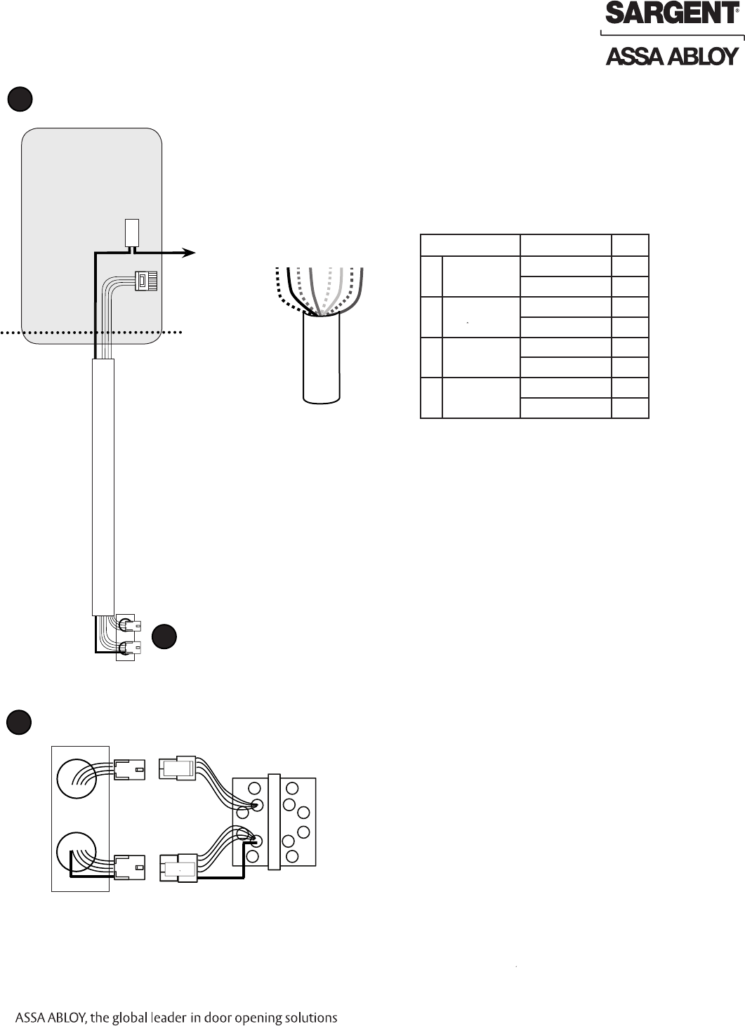
A Frame Harness Installation
Suggested installation of components and wire harness supplied by McKinney:
RJ45-M
Molex-M
Cable: CAT 5e or higher
24 AWG shielded, 100ohm
B-Splice
Crimp Connector
Ceiling
Supplied by CI Cut end / ceiling-side PoE harness:
TIA-568-B Standard Wiring
1
2
3
4
5
6
7
8
Pair Number Wire PIN
1 White/Blue White/Blue 5
Blue 4
2 White/Orange White/Orange 1
Orange 2
3 White/Green White/Green 3
Green 6
4 White/Brown White/Brown 7
Brown 8
Do not confuse pair numbers with pin numbers. A pair number is used for
reference only (e.g.: 10Base-T Ethernet uses pairs 2 & 3). The pin numbers
indicate actual physical locations on the plug and jack.
1. Feed cut end of harness into hole on hinge-side through single access hole.
2. Push one of the connectors back through hole and feed into separate
access hole.
Hinge side of PoE harness:
B
Each of the hinge-side harness connectors should end up threaded through
a different access hole and matched to the same size pin connector from
the door harness:
• 4-pin male Molex connector.
• 6-pin male Molex connector with ground wire.
Frame-Side
Harness
Assembly
(15' length)
24AWG
Stranded
Wire for
Earth
Ground
inside
15' Frame
Harness
Cable
drain wire
concealed
in shrink
tubing
6-pin F
4-pin M
6-pin M
4-pin F
Drain Wire
Frame PoE Hinge (Patent Pending)
PoE Data Hinge Hinge-side harness connectors:
• 4-pin male molex connector
• 6-pin male molex connector with ground wire
Lock-side harness connectors:
• Ring terminal
• (2) 4-pin connectors
• 4-pin Molex connector
• 4-pin connector
B
6 1-800-810-WIRE • www.sargentlock.com • A7764B
Copyright © 2011, Sargent Manufacturing Company, an ASSA ABLOY Group company. All rights reserved.
Reproductions in whole or in part without express written permission of Sargent Manufacturing Company is prohibited.
01/29/11
Profile Series v.S1 PoE Mortise Lock
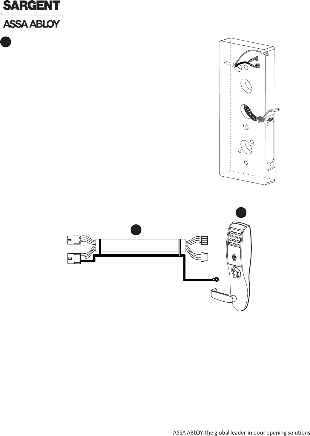
Door Harness Installation
Order of installation may vary.
Refer to appropriate sections for instructions.
1. Prop door open.
2. Tape the two lock-side 4-pin connectors to the ring terminal.
3. Using the ring terminal, carefully fish the assembly through the
door channel to the lock.
4. Remove tape from ring terminal and door harness connectors.
Hinge-side harness connectors:
• 4-pin male Molex connector
• 6-pin male Molex connector with ground wire
Lock-side harness connectors:
• Ring terminal
• (2) 4-pin connectors:
• 4-pin Molex connector
• 4-pin connector
C
Ground
4-Pin
Molex
JST
4-Pin
6-pin M
Cable: CAT 5e,
26 AWG stranded,
shielded, 100ohm
Ring Terminal Secured
to Lock Mounting Plate
PoE Lock
C
4-pin F
Drain Wire
D
JST 4-Pin
From Hinge
Connectors
From Lock body
Ground
Ring Terminal
Inside of Door
01/29/11
1-800-810-WIRE • www.sargentlock.com • A7764B 7
Copyright © 2011, Sargent Manufacturing Company, an ASSA ABLOY Group company. All rights reserved.
Reproductions in whole or in part without express written permission of Sargent Manufacturing Company is prohibited.
Profile Series v.S1 PoE Mortise Lock
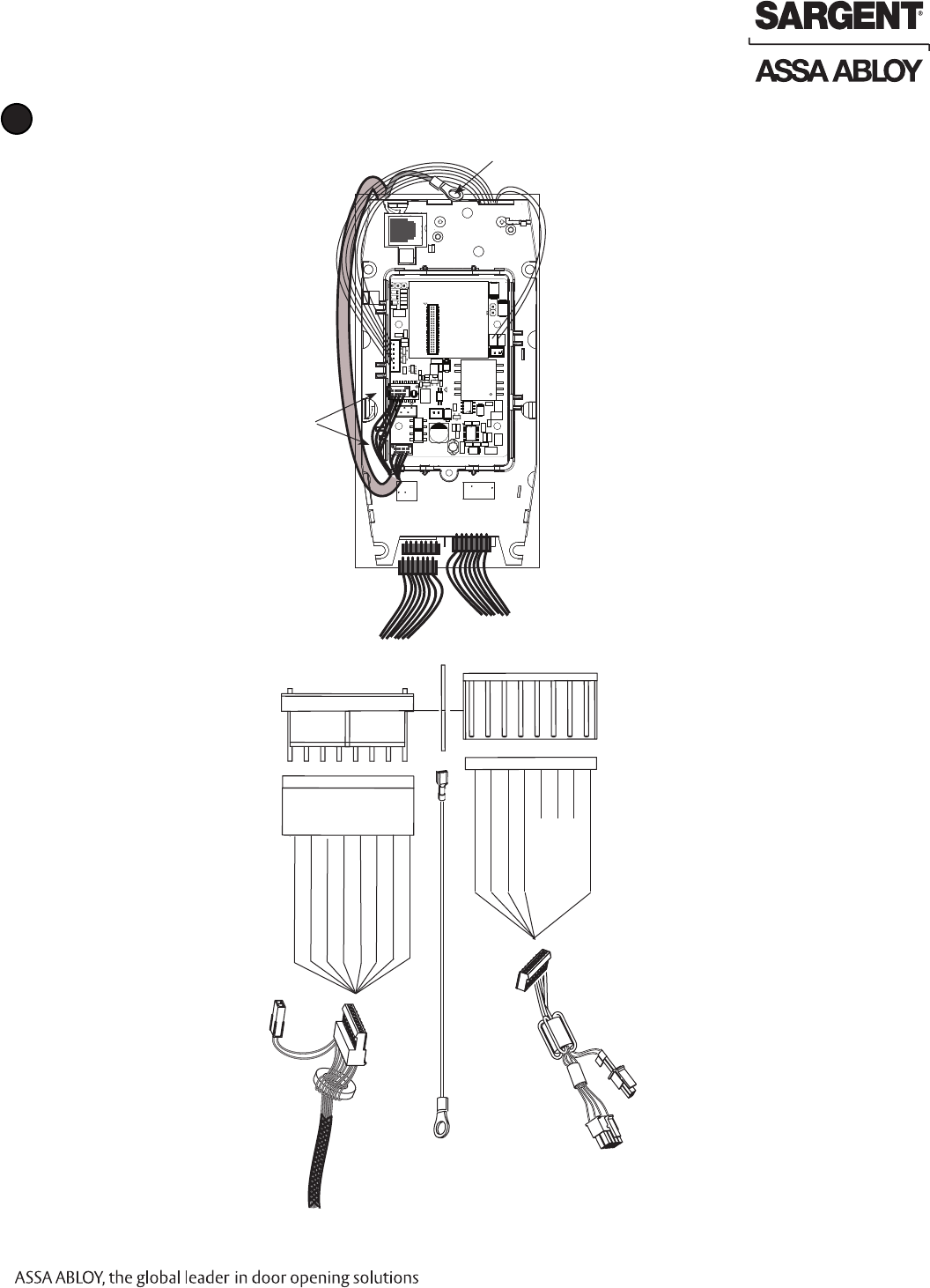
PoE Lock Wiring
D
DX NC (GREEN/WHITE)
RX COM (WHITE)
RX NC (GREEN)
DX (WHITE/BLACK)
LX NO (RED/YELLOW)
LX COM (RED/GREEN
Motor B (BLACK)
Motor A (RED)
TB1
E1 TB2
Controller Board Connectors
(Inside Escutcheon)
8
7
6
5
4
3
2
1
1
2
3
4
5
6
7
8
From
Lock Body
(+) 9VDC (RED)
(-) (BLACK)
AX/DPS NC (PINK)
AX/DPS COM (VIOLET)
Unused
Unused
Unused
EGND (GREEN)
DPS
J7, J4
JST Connectors
(From Hinge)
Ground Ring Terminal
(From Hinge to Top Left Escutcheon Screw)
D10
JP3
C5
C37
U4
D9
U1
R24
R4
C10
R21
TP8
C31
L1
U2
D7
DN1
C12
R8
D2
R5
C4
J7
C16
C34
U3
R14
JP4
C18
R22
C6
Q1
C11
TP1
TP2
J5
R10
D11
DN2
T2
C1
TP3
R3
D5
R1
TP4
C2
TP7
C32
TP5
R7
TP6
C9
R13
C35
R9
C3
R2
D4
C8
R23
TP9
R12 C19
R25
C15
R11
C20
DN3
D6
C13
C7
D1
C33
J2
R6
D3
C14
T1
J3
C36
C17
MTG2
MTG3MTG4
MTG1
J6
C21
J8
R15
R16
J4
D10
JP3
C5
C37
U4
D9
U1
R24
R4
C10
R21
TP8
C31
L1
U2
D7
DN1
C12
R8
D2
R5
C4
J7
C16
C34
U3
R14
JP4
C18
R22
C6
Q1
C11
TP1
TP2
J5
R10
D11
DN2
T2
C1
TP3
R3
D5
R1
TP4
C2
TP7
C32
TP5
R7
TP6
C9
R13
C35
R9
C3
R2
D4
C8
R23
TP9
R12 C19
R25
C15
R11
C20
DN3
D6
C13
C7
D1
C33
J2
R6
D3
C14
T1
J3
C36
C17
MTG2
MTG3
MTG4
MTG1
J6
C21
J8
R15
R16
J4
D10
JP3
C5
C37
U4
D9
U1
R24
R4
C10
R21
TP8
C31
L1
U2
D7
DN1
C12
R8
D2
R5
C4
J7
C16
C34
U3
R14
JP4
C18
R22
C6
Q1
C11
TP1
TP2
J5
R10
D11
DN2
T2
C1
TP3
R3
D5
R1
TP4
C2
TP7
C32
TP5
R7
TP6
C9
R13
C35
R9
C3
R2
D4
C8
R23
TP9
R12 C19
R25
C15
R11
C20
DN3
D6
C13
C7
D1
C33
J2
R6
D3
C14
T1
J3
C36
C17
MTG2
MTG3MTG4
MTG1
J6
C21
J8
R15
R16
J4
D10
JP3
C5
C37
U4
D9
U1
R24
R4
C10
R21
TP8
C31
L1
U2
D7
DN1
C12
R8
D2
R5
C4
J7
C16
C34
U3
R14
JP4
C18
R22
C6
Q1
C11
TP1
TP2
J5
R10
D11
DN2
T2
C1
TP3
R3
D5
R1
TP4
C2
TP7
C32
TP5
R7
TP6
C9
R13
C35
R9
C3
R2
D4
C8
R23
TP9
R12 C19
R25
C15
R11
C20
DN3
D6
C13
C7
D1
C33
J2
R6
D3
C14
T1
J3
C36
C17
MTG2
MTG3
MTG4
MTG1
J6
C21
J8
R15
R16
J4
TB1 E1 TB2
Power
Ring Terminal
From Trim
DPS
8 1-800-810-WIRE • www.sargentlock.com • A7764B
Copyright © 2011, Sargent Manufacturing Company, an ASSA ABLOY Group company. All rights reserved.
Reproductions in whole or in part without express written permission of Sargent Manufacturing Company is prohibited.
01/29/11
Profile Series v.S1 PoE Mortise Lock
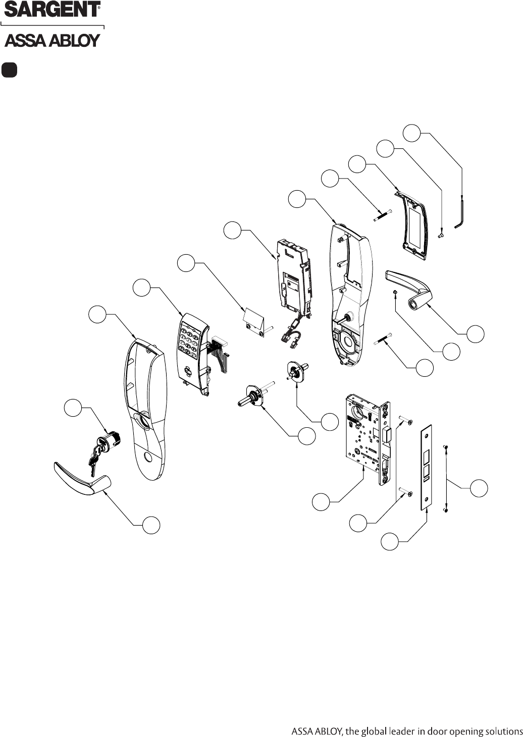
6Parts Breakdown 125 kHz Prox and 13.56 MHz iCLASS
5
7
4
8
9
9
9
16
3
7
9
2
10
9
1
12
11
13
15
14
15
6
01/29/11
1-800-810-WIRE • www.sargentlock.com • A7764B 9
Copyright © 2011, Sargent Manufacturing Company, an ASSA ABLOY Group company. All rights reserved.
Reproductions in whole or in part without express written permission of Sargent Manufacturing Company is prohibited.
Profile Series v.S1 PoE Mortise Lock
1 Outside Lever Reference 8200 Catalog for available levers 1
2 Inside Lever Reference 8200 Catalog for available levers 1
3 82-0493 O/S Escutcheon only with Cylinder 1
82-0495 O/S Escutcheon only without Cylinder 1
4 82-0492 Inside Escutcheon only without Thumb Turn 1
82-4571 Inside Escutcheon only with Thumb Turn 1
5
52-2431 125 kHz Prox Only Bezel Assembly (PA)
1
52-2432 Keypad and 125kHz Prox Bezel Assembly (PK)
OR
52-4420 13.56 MHz iCLASS Only Bezel Assembly (S1-IA)
13.56 MHz reader assembly ships configured for PoE/Hardpower use.
52-4421 Keypad and 13.56 MHz Bezel Assembly (S1-IK)
13.56 mHz reader assembly ships configured for PoE/Hardpower use.
6 52-4424 S1 Controller Assembly (Double Pulse) 1
7 52-3855 Battery Cover Assembly 1
8 01-1212 Security Screw 1
9 52-2427 Profile Screw Pack - Specify Finish (Includes: Fire Stop Plate,
Trim Mounting Screws, Security Allen Wrench)
1
10 Consult Factory Lever Handle Screw (Depends on Lever Style) 1
11 Consult Factory Inside Adapter Assembly (Depends on Lever Style) 1
12 Consult Factory Outside Adapter Assembly (Depends On Lever Style) 1
13 S1-82276-hand-finish Lockbody with Dead Bolt with Cylinder 1
S1-82277-hand-finish Lockbody with Dead Bolt without Cylinder
S1-82278-hand-finish Lockbody without Dead Bolt with Cylinder
S1-82279-hand-finish Lockbody without Dead Bolt without Cylinder
14 82-0084 Faceplate with Dead Bolt (shown) 1
82-0081 Faceplate without Dead Bolt 1
15 77-4336 Mortise Screw Pack - Specify Finish (Includes: Wood and Me-
tal Lock body Screws, Faceplate Screws, and Strike Screws)
1
16 Consult Factory #43 Mortise Cylinder 1
ITEM PART NO. DESCRIPTION QTY.
Parts Breakdown 125 kHz Prox and 13.56 MHz iCLASS, continued
10 1-800-810-WIRE • www.sargentlock.com • A7764B
Copyright © 2011, Sargent Manufacturing Company, an ASSA ABLOY Group company. All rights reserved.
Reproductions in whole or in part without express written permission of Sargent Manufacturing Company is prohibited.
01/29/11
Profile Series v.S1 PoE Mortise Lock
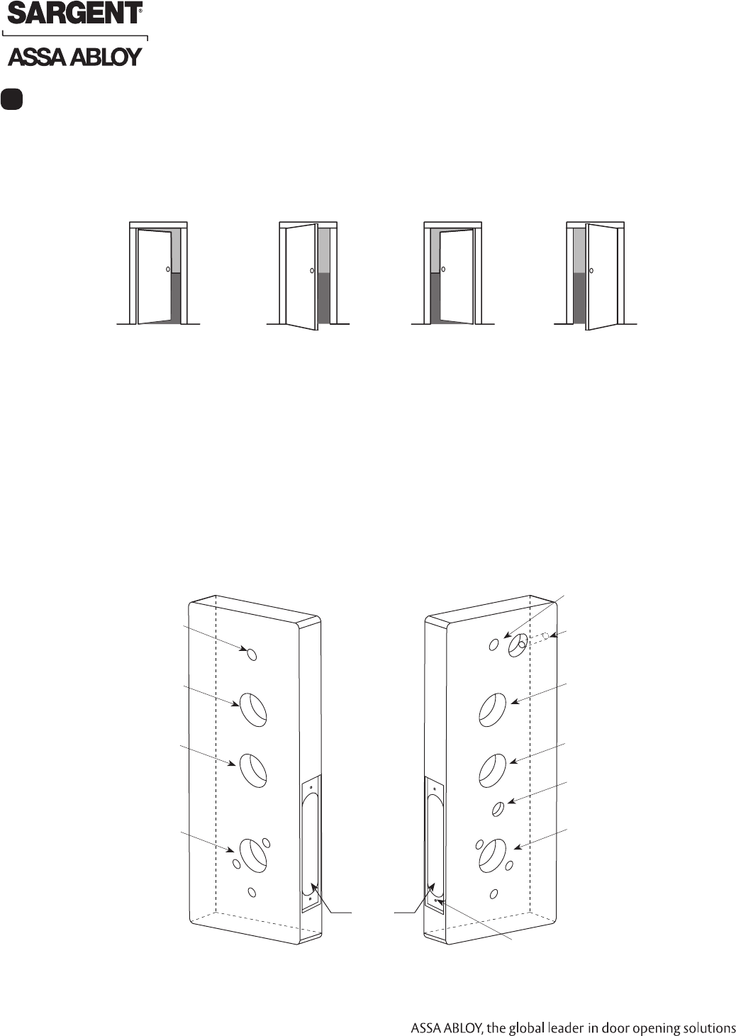
Stand on outside of locked door when determining door hand.
B. Door Preparation
Outside of Door Inside of Door
Step #1 – Door Preparation
A. Verify Hand and Bevel of Door
Lock Installation
Ribbon Cable Hole
(Controller to Keypad)
Outside of Cylinder Hole
(only with cylinder installation)
Lever Handle Hole
Through-bolt Hole
Ribbon Cable Hole
(Controller to Keypad)
Inside of Lockbody Wire Hole
(only with cylinder installation)
Lever Handle Hole
*Raceway
Through-bolt Hole
Pre-drilled and/or
Tapped Holes
Mortised
Pocket
Prior to installation, all holes must be free of burrs, debris and sharp edges.
Prepare door according to appropriate template (see website www.intelligentopenings.com):
• Manufacturer Door Template: 4533
LH
Left Hand
Hinges Left
Open Inward
LHRB
Left Hand
Reverse Bevel
Hinges Left
Open Outward
RH
Right Hand
Hinges Right
Open Inward
RHRB
Right Hand
Reverse Bevel
Hinges Right
Open Outward
8
*Note: Raceway placement in
document is approximate.
Thumb Turn Lever Hole
Fig. 1A
Fig. 1B
01/29/11
1-800-810-WIRE • www.sargentlock.com • A7764B 11
Copyright © 2011, Sargent Manufacturing Company, an ASSA ABLOY Group company. All rights reserved.
Reproductions in whole or in part without express written permission of Sargent Manufacturing Company is prohibited.
Profile Series v.S1 PoE Mortise Lock
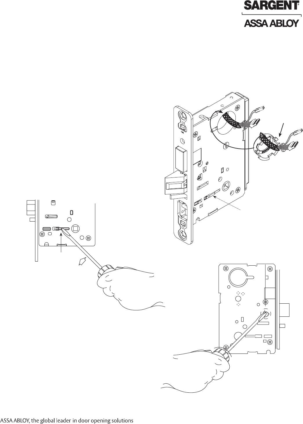
Step #2 – How to Change Hand of Lockbody
Beveled surface of latchbolt must face strike.
The deadlatch is self adjusting.
To change the hand of the latchbolt:
1. Insert the blade of a slotted screwdriver (>1/4”)
into the spade shape slot behind latch.
2. Rotate the screwdriver 90° to push latchbolt
out until back of bolt clears lock case front.
3. Rotate latchbolt 180° until the latchbolt
drops back into the lockbody.
Note: Latch cannot be unscrewed.
Red surface of locking piece must face the outside/locked side of door. To rotate locking piece (Fig. 2A):
1. Position lock body with red surface of locking piece visible.
2. Insert blade type screwdriver into locking piece slot to rotate locking piece toward back of lock body.
3. Rotate the locking piece 180° until RED surface is on opposite side.
Note: Red indicates locked side (outside).
Wire harness MUST exit through the
inside/non-cylinder side of the lockbody.
B. Retaining Ring
Make sure the plastic retaining ring is seated
correctly (Fig. 2B):
1. The wires and the plastic retaining ring
must be located on the non-cylinder side.
2. Orient the plastic retaining ring so that the word
Bottom is located at the bottom of the cylinder hole.
3. Route the wires from the top of the cylinder hole
into the slot on the top of the plastic retaining ring,
NOT through the retaining ring.
Push In
Right Hand Shown
Locking
Guide
Slot
Fig. 2A
Fig. 2C
A. Reverse Lock Hand
C. Reverse Latch Hand
Red Locking Piece
Indicates Locked Side
Plastic
Retaining
Ring
Outside of Door
Fig. 2B
Slot
12 1-800-810-WIRE • www.sargentlock.com • A7764B
Copyright © 2011, Sargent Manufacturing Company, an ASSA ABLOY Group company. All rights reserved.
Reproductions in whole or in part without express written permission of Sargent Manufacturing Company is prohibited.
01/29/11
Profile Series v.S1 PoE Mortise Lock
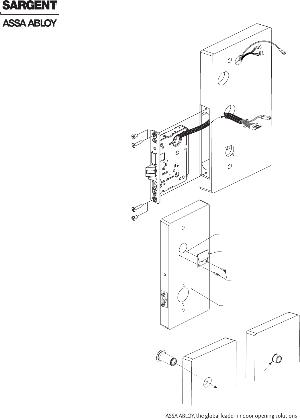
Step #3 – Install Lockbody
1. Feed the wires first through the mortise pocket
and out the inside prep, followed by the lock-
body (Fig. 3A).
Note: Connectors and wires must be fed
through non-cylinder side.
2. The wires from the lockbody exit the inside door
prep through the mortise cutout.
3. Loosely secure the lockbody in the door with
two #12 x 1-1/4” wood screws or #12-24 x 1/2”
machine screws.
Note: Do not completely tighten at this time.
Ground
Wire
(2) 4-Pin
Connectors
From Hinge
(2) #12-24 x 1/2” Long
Flat Head Screws
for Metal Doors
(2) #12 x 1-1/4” Long
Flat Head Screws
for Metal Doors
Fig. 3A
Mortise
Connectors
Inside of Door
Step #4 – Door Options
A. Fire Stop Plate (P/N 52-0033)
Fire-rated doors require a fire stop plate on
the outside of the door (Fig. 4A).
1. Drill (2) 1/8" x 1-1/4" deep holes in the
door if not already present.
Refer to template for fire-stop
prep locations.
2. Attach with flap up and
out using (2) #8 x 1/2”
self-tapping screws for
wood and metal doors.
B. Weather Conduit (52-2847)
Install weather conduit on
NON FIRE-RATED exterior doors only (Fig. 4B).
1. Carefully insert the weather conduit into the
ribbon cable hole on the inside of the door.
2. Place the O-ring around the weather conduit
on the outside and up against the door (Fig. 4C)
Outside of Door
(2) 1/8” Diameter
Holes Required
Fire Stop Plate
(2) #8 Self-Tapping
Screws for Wood
and Metal Doors
(2) Through-bolt Holes
Fig. 4A
Outside of Door
Fig.4B
Fig.4C
Ribbon Cable Hole
O-Ring
01/29/11
1-800-810-WIRE • www.sargentlock.com • A7764B 13
Copyright © 2011, Sargent Manufacturing Company, an ASSA ABLOY Group company. All rights reserved.
Reproductions in whole or in part without express written permission of Sargent Manufacturing Company is prohibited.
Profile Series v.S1 PoE Mortise Lock
Step #6 – Install Outside Escutcheon and Lever Assembly
1A. For fire rated doors, feed ribbon cable with connector and ground wire from
outside of door through weatherseal gasket and fire stop plate (Fig. 6A).
Note: Install ribbon cable with cable exiting down
1B. For non-fire rated doors, feed ribbon cable with connector and ground
wire from outside of door through weatherseal gasket (if used)
and weather conduit (Fig. 6A).
Note: Install ribbon cable with cable exiting down
2. With outside lever horizontal, locate the outside escutcheon on the door,
while directing the mounting posts through the door and lock body (Fig. 6B).
Make sure the lever spindle is properly engaged in lock.
3. On the inside of the door, insert spindle into square hole
of mortise lock.
4. Slide inside adapter and plate
assembly over spindle and loosely
secure with 2 through bolt
screws (#8-32 x 5/8”).
Note: For 8276 and 8278,
loosely thread cylinder
through escutcheon
and into the lock body
before tightening the
lock case screws
and escutcheon
through bolts.
Gasket 82-0500
Step #5 – Install Gasket (for Exterior Doors)
1. Carefully remove the backing from the gasket.
2. Apply gasket to escutcheon:
• Starting in one place, press the adhesive side
of the gasket firmly against the escutcheon.
• Work around the escutcheon, pressing the sticky side
of the gasket firmly against the escutcheon edge.
• The gasket should be aligned so that all edges
of the escutcheon are covered.
3. Attach escutcheon to the door after the wires
are connected.
Note: The 43 cylinder may be used with or without a gasket.
Fig. 5A
Inside of Door
Mortise Lock body
and AX Connectors
Fig. 6B
Reader
Cable
Ground
Wire (E1)
Antenna
(iCLASS)
JST 4-Pin
From Hinge
Ground
Ring Terminal
Antenna
(iCLASS
only)
Fig. 6A
Outside of Door
Keypad
Ribbon
Cable
Ground
Wire (E1)
Keypad
Ribbon
Cable
Ground
Wire
(E1)
Gasket
Antenna
(iCLASS)
Only
Fig. 5B
14 1-800-810-WIRE • www.sargentlock.com • A7764B
Copyright © 2011, Sargent Manufacturing Company, an ASSA ABLOY Group company. All rights reserved.
Reproductions in whole or in part without express written permission of Sargent Manufacturing Company is prohibited.
01/29/11
Profile Series v.S1 PoE Mortise Lock
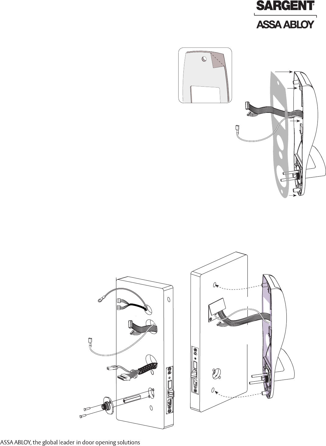
Step #7 – Escutcheon Wire Connections
Images are shown without gasket. If gasket is necessary,
refer to Step #5.
Before the controller is attached to the door:
1. Attach the reader assembly
ribbon cable into the back of the
controller assembly (side that
faces towards the door when
mounted (Fig. 7C Detail).
2. Attach the antenna to the
circuit board in the plastic
housing under the
controller assembly.
Note: The difference between
the wiring for the iCLASS 13.56
MHz reader and the 125 kHz
Prox is that the iCLASS wiring
includes an antenna wire.
3. Attach the ground wire
to the bottom of the
controller assembly
(E1, Fig. 7A).
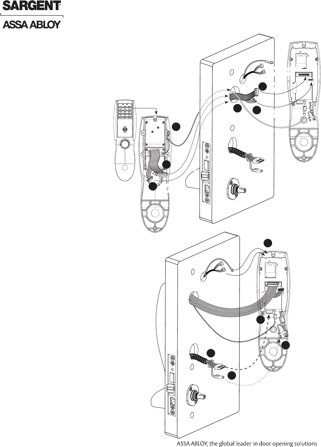
Step #8 – Additional Wiring Connections
Lock, DPS and raceway wire connections:
1. Connect the cable from the mortise lock
to the bottom of the controller
assembly (TB1, Fig. 8A).
2. Connect the AX/DPS connector
to the 2-pin harness.
3. Push the two connectors from the
raceway over the controller assembly,
through the gap between the
plastic controller assembly
and the escutcheon,
to the front of the
circuit board.
Mortise
Connector
Ground
Wire
Fig. 8A
Back
AX/DPS
Inside of Door
Ground
Ring
Terminal
1
3
2
Outside
Escutcheon
Antenna
(iCLASS only)
Unused
TB1
Reader
Cable
Ground
Wire
Fig. 7A
2
Outside
Escutcheon
1
2
3
Ground
Wire
Reader
Cable
Antenna
(iCLASS)
1
Ground Ring
Terminal
3
4-Pin
Connectors From Hinge
2
Antenna
(iCLASS only)
Reader
Cable
1
4-Pin Connectors
From Hinge
01/29/11
1-800-810-WIRE • www.sargentlock.com • A7764B 15
Copyright © 2011, Sargent Manufacturing Company, an ASSA ABLOY Group company. All rights reserved.
Reproductions in whole or in part without express written permission of Sargent Manufacturing Company is prohibited.
Profile Series v.S1 PoE Mortise Lock
Step #9 – Ciruit Board Wiring
Before installing escutcheon, route raceway cables and ground attach to
front of circuit board.
Turn the controller assembly over:
1. Route the raceway connectors over the top of the controller assembly
and plug into the front of the circuit board (side that faces out when
mounted (J7, J4; Fig. 9A).
2. Route the 2 ground ring terminals, one from the lock and the other
from the hinge wiring, over the top of the controller assembly and con-
nect both to the top escutcheon screw.
Note: Connectors go on only one way.
Do not offset connectors and make sure they are completely seated.
Inside of Door
Ground
Ring
Terminal
Fig. 9A
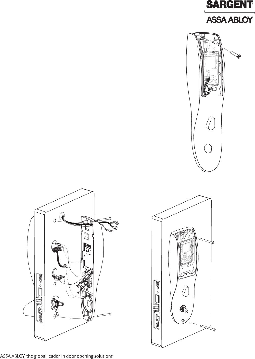
Step #10 – Install Inside Escutcheon
1. Gently fold the excess ribbon connector and ground wire into the
top hole, JST connectors and ground wire into offset middle hole,
and mortise and AX/DPS wires into bottom hole, being careful not
to pinch wires (Fig. 10A).
2. Insert (2) #8-32 x 1-1/4" screws through inside escutcheon and
thread into outside escutcheon (Fig. 10B)
Straighten escutcheons and tighten securely.
Inside of Door
Fig. 10B
Fig. 10A
16 1-800-810-WIRE • www.sargentlock.com • A7764B
Copyright © 2011, Sargent Manufacturing Company, an ASSA ABLOY Group company. All rights reserved.
Reproductions in whole or in part without express written permission of Sargent Manufacturing Company is prohibited.
01/29/11
Profile Series v.S1 PoE Mortise Lock
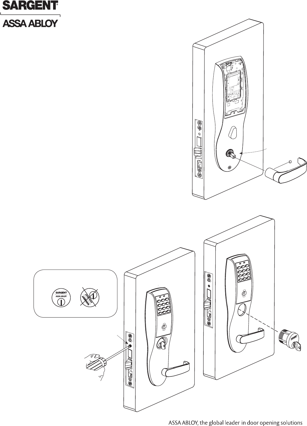
1. Slide lever handle onto spindle until fully seated (Fig. 11A).
2. Tighten the set screw securely with 1/8” hex wrench.
Step #11 – Install Inside Lever
Step #12 – Install and Secure Cylinder
1. Slide cylinder through the spring and rosette/collar
and screw into lockbody, rotating the cylinder
clockwise (Fig. 12A).
Cylinder should be flush with rosette/collar.
Note: SARGENT logo must be horizontal and on
the top of the cylinder (Fig. 12B).
2. Secure the cylinder by tightening cylinder clamp
screw located above the deadbolt using #2 Phillips
screwdriver (Fig. 12C).
3. Using the key, test cylinder functions:
• 8278 Function: Key retracts latch-.
• 8276 Function: Key retracts latch and projects
and retracts deadbolt-.
Fig. 12A
Key
Type 43 Cylinder
Cylinder Clamp Screw
#2 Phillips
Screwdriver Outside of Door
Fig. 12C
Inside Lever
Fig. 11A
Inside of Door
Spindle
Set Screw
Fig. 12B
Position cylinder so that the
SARGENT logo is right-side up.
Correct Incorrect
01/29/11
1-800-810-WIRE • www.sargentlock.com • A7764B 17
Copyright © 2011, Sargent Manufacturing Company, an ASSA ABLOY Group company. All rights reserved.
Reproductions in whole or in part without express written permission of Sargent Manufacturing Company is prohibited.
Profile Series v.S1 PoE Mortise Lock
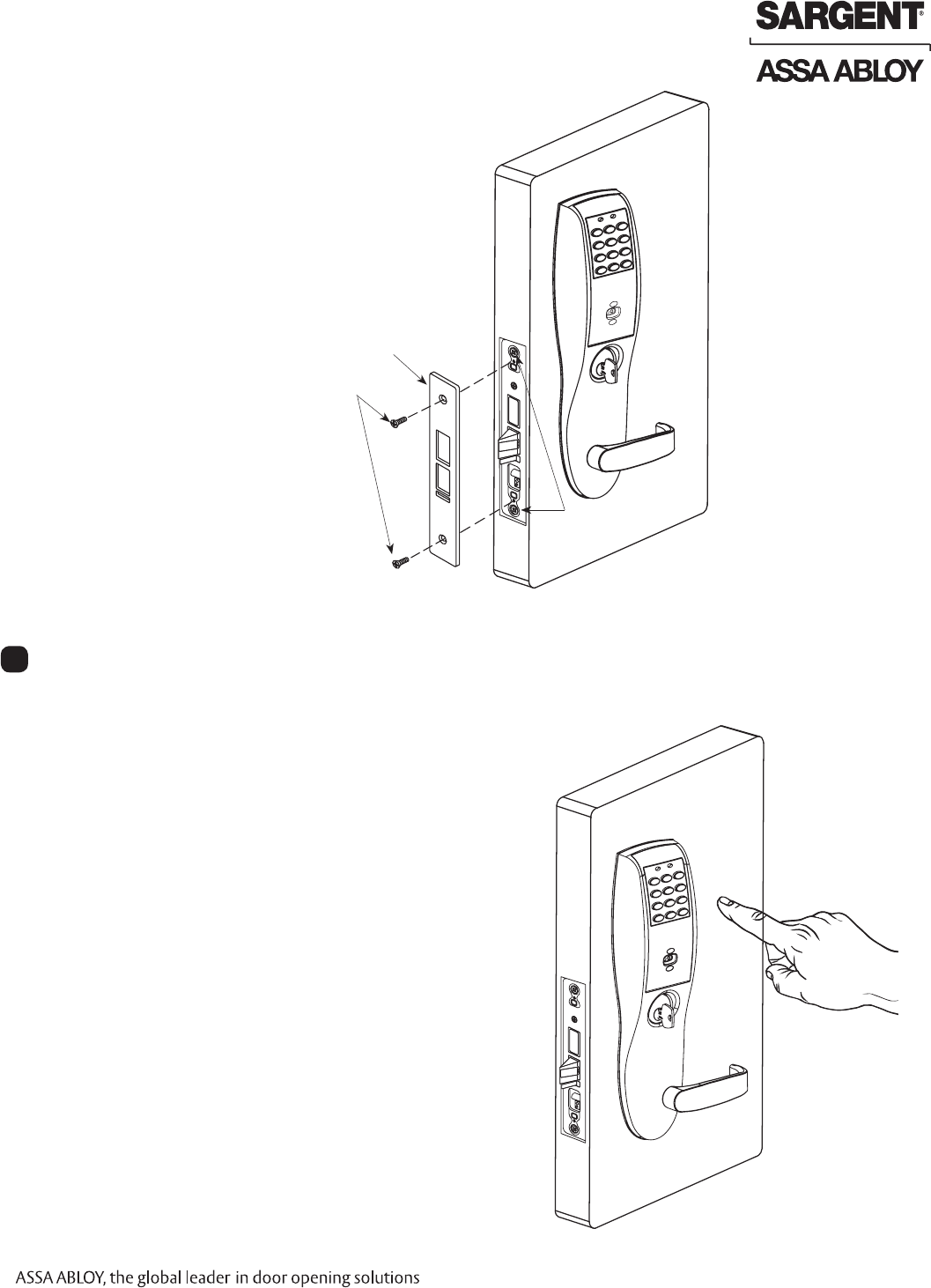
Step #13 – Attach Front Plate
Attach front plate with (2) flat head screws.
1A. For 8276- and 8278- function mortise locks with cylinders:
• Insert key into cylinder and rotate.
There should be no friction against lock case,
wire harness or any other obstructions.
Refer to Section 6, Step 8 Wiring
if harness friction exists).
• Check that the key retracts the latch:
The key should rotate freely.
1B. For 8276- and 8277- function:
• Throw the deadbolt:
Check that the key retracts both the
deadbolt and the latch.
• Try the inside lever:
Ensure it retracts latch and deadbolt (if provided).
2. Use a prox 125 kHz or 13.56 MHz iCLASS credential,
or keypad PIN code set up with the Network and Lock
Configuration Tool to unlock outside lever and retract latch.
Refer to Network Lock and Configuration Tool user manual
(WFMN1D) for information on how to configure and program
v.S1 locks.
Operational Check
9
Fig. 13A
Outside of Door
Front Plate
(2) Flat Head Screws
Lock body Screws

SARGENT Manufacturing
100 Sargent Drive
New Haven, CT 06511 USA
800-810-WIRE (9473) • www.sargentlock.com
Founded in the early 1800s, SARGENT® is a market leader in locksets, cylinders, door closers, exit devices,
electro-mechanical products and access control systems for new construction, renovation, and replacement applications.
The company’s customer base includes commercial construction, institutional, and industrial markets.
Copyright © 2011, Sargent Manufacturing Company, an ASSA ABLOY Group company. All rights reserved.
Reproduction in whole or in part without the express written permission of Sargent Manufacturing Company is prohibited.
ASSA ABLOY is the global leader in door opening solutions, dedicated to
satisfying end-user needs for security, safety and convenience. A7764B-01/11