Belkin F5D7231P High-Speed Mode Wireless G Router w/ Print Server User Manual P74606 F5D7231 4P man indd
Belkin International, Inc. High-Speed Mode Wireless G Router w/ Print Server P74606 F5D7231 4P man indd
Belkin >
Contents
Users Manual Part 3
28
Configuring and Using the USB Print Server
Configuring and Using the USB Print Server
29
section
2
1
3
4
5
6
7
8
9
10
11
12
13
Using the Print Server
Print Server Configuration Screen
For proper operation of the Print Server, install the printer’s drivers and
software on each computer from which you plan to print. The Belkin Print
Server Port must also be installed on each of these computers. See page 26
of this manual for more information and instructions.
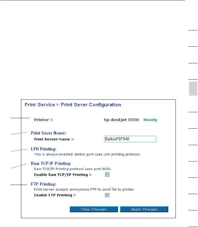
The Print Server Configuration screen is the central point in the Router where
you can find the printer status (ready/not ready) and make certain adjustments.
See page 52 in this manual for directions to access the Advanced Web Based
User Interface.
Printer field (1)
This line shows you the name of the printer that is connected to the Print
Server and its status.
Print Server Name (2)
The Print Server name identifies the Print Server. If you wish, you can
change it by typing in a new name such as “My Print Server” then clicking
“Apply Changes”.
(1)
(2)
(3)
(4)
(5)
30
Configuring and Using the USB Print Server
Configuring and Using the USB Print Server
31
section
2
1
3
4
5
6
7
8
9
10
11
12
13
LPR Printing (3)
The Belkin Printer Port uses LPR as the main printing method.
Raw TCP/IP Printing (4)
This feature allows clients to print to the Print Server using the standard TCP/IP printer
port built into Windows XP and 2000, instead of the Belkin Port Monitor. Using Raw
Printing requires that you configure all port parameters manually. It is not recommended
for users unfamiliar with TCP/IP printing.
FTP Printing (5)
This feature enables the printer to receive print jobs sent by FTP (see “Using FTP Printing”
on this page). Disabling this feature will prevent FTP jobs from printing
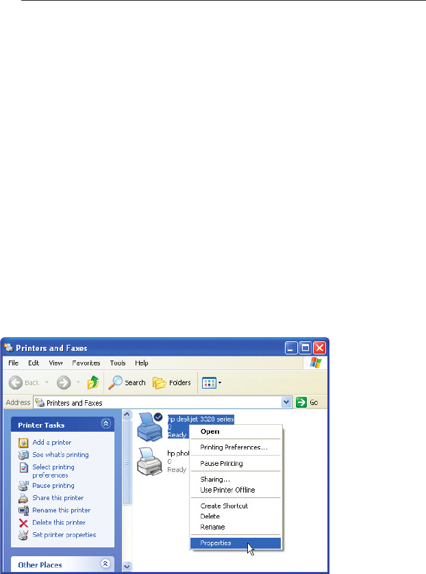
Using FTP Printing
This section describes how to send print jobs to the printer using FTP.
1. In Windows, select the printer’s properties.
30
Configuring and Using the USB Print Server
Configuring and Using the USB Print Server
31
section
2
1
3
4
5
6
7
8
9
10
11
12
13
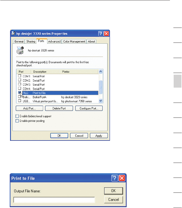
2. Set the printer port to “File”, click “Apply”.
3. Print the document using the printer that you configured. A
dialogue box will open prompting you to name the print file.
After naming the file, click “OK”. A file will be saved to the user’s
default Windows directory (typically “C:\” or “C:\Documents and
Settings\<user’s name>”).
32
Configuring and Using the USB Print Server
Configuring and Using the USB Print Server
33
section
2
1
3
4
5
6
7
8
9
10
11
12
13
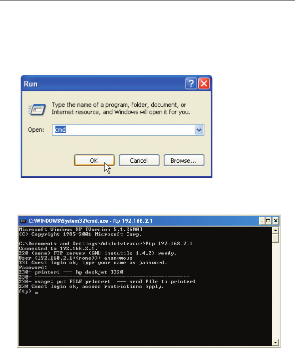
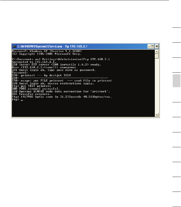
4. On the Windows desktop, click “Start>Run” and type in “cmd” for
Windows XP and 2000 or “command” for Windows 98SE and Me;
click “OK” to open a “Command/MS-DOS Prompt” window.
5. At the prompt, type “ftp” followed by the IP address of the Router
(default is 192.168.2.1); press the “Enter” key to create an FTP
connection with the Print Server.
6. When the connection is made, the user will be prompted to
enter a user name and a password. The user name for the Print
Server is “anonymous”; the password should be left blank. After
a successful login, a list of the printers connected to the Print
Server will appear, followed by simple usage instructions for how
to print the file.
32
Configuring and Using the USB Print Server
Configuring and Using the USB Print Server
33
section
2
1
3
4
5
6
7
8
9
10
11
12
13
7. At the prompt, type “put”, followed by the file path and file
name, followed by the printer number (for example, “put c:
\example printer1”).
8. The file will be sent to the Print Server. When the transfer is
complete, another prompt will appear. If finished, type “quit” and
press “Enter” to end the FTP session. Then, close the “Command
Prompt” window.
Note: FTP Printing by default is enabled in the Print Server. It can be
disabled using the Router’s Web-Based Setup Interface. See page 29
for details.

34
Alternate Setup Method
Alternate Setup Method
35
section
2
1
3
4
5
6
7
8
9
10
11
12
13
The Advanced User Interface is a web-based tool that you can use to
set up the Router if you don’t want to use the Easy Install Wizard. You
can also use it to manage advanced functions of the Router. From the
Advanced User Interface, you can perform the following tasks:
• View the Router’s current settings and status.
• Configure the Router to connect to your ISP with the settings that
they provided you.
• Change the current network settings such as the Internal IP
address, the IP address pool, DHCP settings and more.
• Set the Router’s firewall to work with specific applications
(port forwarding).
• Set up security features such as client restrictions, MAC address
filtering, WEP and WPA.
• Enable the DMZ feature for a single computer on your network.
• Change the Router’s internal password.
• Enable/Disable UPnP (Universal Plug-and-Play).
• Reset the Router.
• Back up your configuration settings.
• Reset the Router’s default settings.
• Update the Router’s firmware.
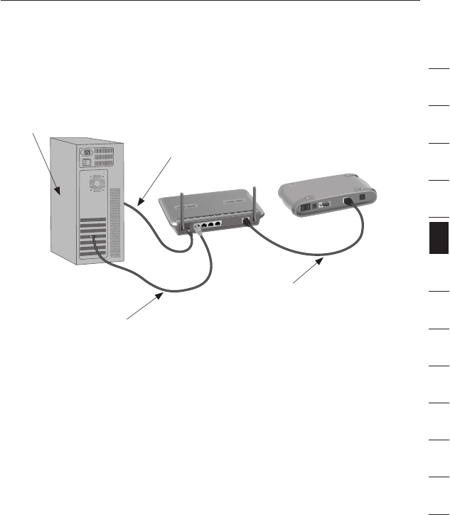
Step 1 Connecting your Router
1.1 Turn off the power to your modem by unplugging the power
supply from the modem.
1.2 Locate the network cable that is connected between your modem
and your computer and unplug it from your computer, leaving the
other end connected to your modem.
1.3 Plug the loose end of the cable you just unplugged into the green
port on the back of the Router labeled “Connection to Modem”.
1.4 Connect the new blue network cable (included) from the back of
the computer to one of the blue ports labeled “1–4”. Note: It does
not matter which numbered port you choose.
34
Alternate Setup Method
Alternate Setup Method
35
section
2
1
3
4
5
6
7
8
9
10
11
12
13
1.5 Turn your cable or DSL modem on by reconnecting the power
supply to the modem.
Note: Your Router may have ports in different locations than
depicted in the illustration above.
1.6 Before plugging the power cord into the Router, plug the cord
into the wall, then plug the cord into the Router’s power jack.
1.7 Verify that your modem is connected to the Router by checking
the lights on the front of the Router. The green light labeled
“WAN” should be ON if your modem is connected correctly to the
Router. If it is not, recheck your connections.
1.8 Verify that your computer is connected properly to the Router
by checking the lights labeled “LAN 1,2,3,4”. The light which
corresponds to the numbered port connected to your computer
should be ON, if your computer is connected properly. If it is not,
recheck your connections.
To Power Adapter
Mac or PC computer that was originally
connected to the cable or DSL modem
Network cable
(to computer)
Existing networking cable
(came with modem)
36
Alternate Setup Method
Alternate Setup Method
37
section
2
1
3
4
5
6
7
8
9
10
11
12
13
Step 2 Set your Computer’s Network Settings to Work
with a DHCP Server
See the section in this manual called “Manually Configuring Network
Settings” for directions.
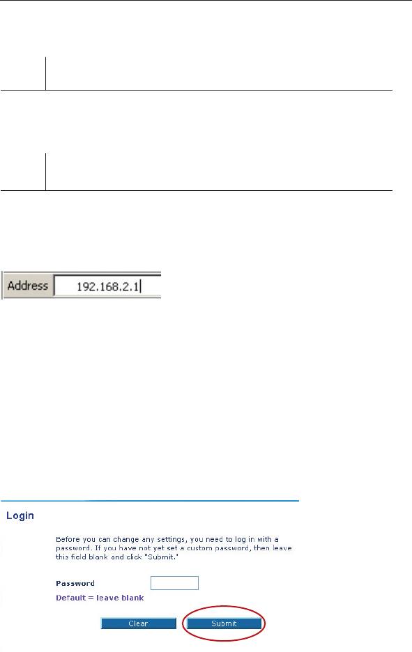
Step 3 Configuring the Router Using the Web-Based
Advanced User Interface
Using your Internet browser, you can access the Router’s Web-Based
Advanced User Interface. In your browser, type “192.168.2.1” (you do
not need to type in anything else such as “http://” or “www”). Then
press the “Enter” key.
PLEASE NOTE: If you have difficulty accessing the Router’s web-
based interface, go to Section 7 of the user manual titled “Manually
Configuring Computer Network Settings”.
Logging into the Router
You will see the Router’s home page in your browser window. The
home page is visible to any user who wants to see it. To make any
changes to the Router’s settings, you have to log in. Clicking the
“Login” button or clicking on any one of the links on the home page
will take you to the login screen. The Router ships with no password
entered. In the login screen, leave the password blank and click the
“Submit” button to log in.
36
Alternate Setup Method
Alternate Setup Method
37
section
2
1
3
4
5
6
7
8
9
10
11
12
13
Logging out of the Router
One computer at a time can log in to the Router for the purposes
of making changes to the settings of the Router. Once a user has
logged in to make changes, there are two ways that the computer
can be logged out. Clicking the “Logout” button will log the computer
out. The second method is automatic. The login will time out after a
specified period of time. The default login time out is 10 minutes. This
can be changed from 1 to 99 minutes. For more information, see the
section in this manual titled “Changing the Login Timeout Setting”.
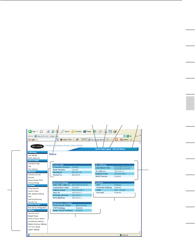
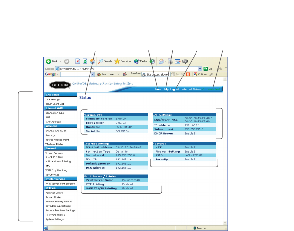
Understanding the Web-Based Advanced User Interface
The home page is the first page you will see when you access the
Advanced User Interface (UI). The home page shows you a quick view
of the Router’s status and settings. All advanced setup pages can be
reached from this page.
1. Quick-Navigation Links
You can go directly to any of the Router’s advanced UI pages by
clicking directly on these links. The links are divided into logical
categories and grouped by tabs to make finding a particular
setting easier to find. Clicking on the purple header of each tab
will show you a short description of the tab’s function.
(1)
(10) (2) (5) (4) (3)
(9) (8)
(7)
(6)
38
Alternate Setup Method
Alternate Setup Method
39
section
2
1
3
4
5
6
7
8
9
10
11
12
13
2. Home Button
The home button is available in every page of the UI. Pressing
this button will take you back to the home page.
3. Internet Status Indicator
This indicator is visible in all pages of the Router, indicating
the connection status of the Router. When the indicator says
“connection OK” in GREEN, the Router is connected to the
Internet. When the Router is not connected to the Internet, the
indicator will read “no connection” in RED. The indicator is
automatically updated when you make changes to the settings of
the Router.
4. Login/Logout Button
This button enables you to log in and out of the Router with the
press of one button. When you are logged into the Router, this
button will change to read “Logout”. Logging into the Router will
take you to a separate login page where you will need to enter a
password. When you are logged in to the Router, you can make
changes to the settings. When you are finished making changes,
you can log out of the Router by clicking the “Logout” button. For
more information about logging into the Router, see the section
called “Logging into the Router”.
(1)
(10) (2) (5) (4) (3)
(9) (8)
(7)
(6)

38
Alternate Setup Method
Alternate Setup Method
39
section
2
1
3
4
5
6
7
8
9
10
11
12
13
5. Help Button
The “Help” button gives you access to the Router’s help pages.
Help is also available on many pages by clicking “more info” next
to certain sections of each page.
6. LAN Settings
Shows you the settings of the Local Area Network (LAN) side of
the Router. Changes can be made to the settings by clicking on
any one of the links (IP Address, Subnet Mask, DHCP Server) or
by clicking the “LAN” Quick Navigation link on the left side of
the screen.
7. Features
Shows the status of the Router’s NAT, firewall, and wireless
features. Changes can be made to the settings by clicking on any
one of the links or by clicking the “Quick Navigation” links on the
left side of the screen.
8. Internet Settings
Shows the settings of the Internet/WAN side of the Router that
connects to the Internet. Changes to any of these settings can
be made by clicking on the links or by clicking on the “Internet/
WAN” Quick Navigation link on the left side of the screen.
9. Version Info
Shows the firmware version, boot-code version, hardware
version, and serial number of the Router.
10. Page Name
The page you are on can be identified by this name. This manual
will sometimes refer to pages by name. For instance “LAN > LAN
Settings” refers to the “LAN Settings” page.
40
Alternate Setup Method
Alternate Setup Method
41
section
2
1
3
4
5
6
7
8
9
10
11
12
13
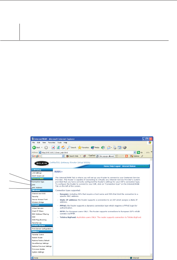
Step 4 Configuring your Router for Connection to your Internet
Service Provider (ISP)
The “Internet/WAN” tab is where you will set up your Router to
connect to your Internet Service Provider (ISP). The Router is capable
of connecting to virtually any ISP’s system provided you have
correctly configured the Router’s settings for your ISP’s connection
type. Your ISP connection settings are provided to you by your ISP.
To configure the Router with the settings that your ISP gave you,
click “Connection Type” (A) on the left side of the screen. Select
the connection type you use. If your ISP gave you DNS settings,
clicking “DNS” (B) allows you to enter DNS address entries for ISPs
that require specific settings. Clicking “MAC address” (C) will let you
clone your computer’s MAC address or type in a specific WAN MAC
address, if required by your ISP. When you have finished making
settings, the “Internet Status” indicator will read “connection OK” if
your Router is set up properly.
(A)
(B)
(C)